Embed Size (px)
Citation preview

Ivelin Georgiev, Kyle E. Roberts, Pablo Gainza, Mark A. Hallen, and Bruce R.Donald
Copyright (C) 2001-2015 Bruce Donald Lab, Duke University

Contents
1 Introduction 31.1 Modeling Flexibility . . . . . . . . . . . . . . . . . . . . . . . . . . . . . . . . . . . . 41.2 What’s new in Version 2? . . . . . . . . . . . . . . . . . . . . . . . . . . . . . . . . . 41.3 What’s new in Version 2.2β? . . . . . . . . . . . . . . . . . . . . . . . . . . . . . . . 6
2 Installation 8
3 Setting up OSPREY 103.1 Compute Node Setup . . . . . . . . . . . . . . . . . . . . . . . . . . . . . . . . . . . 103.2 Starting OSPREY . . . . . . . . . . . . . . . . . . . . . . . . . . . . . . . . . . . . . 11
3.2.1 Starting OSPREY using MPI . . . . . . . . . . . . . . . . . . . . . . . . . . . 113.2.2 Starting OSPREY using Java Threads . . . . . . . . . . . . . . . . . . . . . . 123.2.3 Main Configuration File . . . . . . . . . . . . . . . . . . . . . . . . . . . . . . 13
4 OSPREY Input Model 174.1 Setting up the Input Structure . . . . . . . . . . . . . . . . . . . . . . . . . . . . . . 174.2 Rotamer Libraries . . . . . . . . . . . . . . . . . . . . . . . . . . . . . . . . . . . . . 194.3 Energy Function . . . . . . . . . . . . . . . . . . . . . . . . . . . . . . . . . . . . . . 214.4 Perturbations . . . . . . . . . . . . . . . . . . . . . . . . . . . . . . . . . . . . . . . . 26
5 OSPREY Commands 295.1 GMEC-based Redesign . . . . . . . . . . . . . . . . . . . . . . . . . . . . . . . . . . . 31
5.1.1 Configuration Files . . . . . . . . . . . . . . . . . . . . . . . . . . . . . . . . . 315.1.2 Output Files . . . . . . . . . . . . . . . . . . . . . . . . . . . . . . . . . . . . 465.1.3 Identification of current rotamers . . . . . . . . . . . . . . . . . . . . . . . . . 505.1.4 Performing Backrubs . . . . . . . . . . . . . . . . . . . . . . . . . . . . . . . . 505.1.5 Multistate design with comets . . . . . . . . . . . . . . . . . . . . . . . . . . 52
5.2 Redesign Using K∗ . . . . . . . . . . . . . . . . . . . . . . . . . . . . . . . . . . . . . 545.2.1 Configuration Files . . . . . . . . . . . . . . . . . . . . . . . . . . . . . . . . . 555.2.2 Output Files . . . . . . . . . . . . . . . . . . . . . . . . . . . . . . . . . . . . 60
5.3 Residue Entropy Computation . . . . . . . . . . . . . . . . . . . . . . . . . . . . . . 645.3.1 Configuration Files . . . . . . . . . . . . . . . . . . . . . . . . . . . . . . . . . 645.3.2 Output Files . . . . . . . . . . . . . . . . . . . . . . . . . . . . . . . . . . . . 65
6 Special Types of Redesign 686.1 Modeling Explicit Waters . . . . . . . . . . . . . . . . . . . . . . . . . . . . . . . . . 68
1

7 OSPREY via an Example - redesigning a protein for small molecule affinity 70
8 OSPREY via an Example: Redesigning a protein-peptide interface 82
A OSPREY Class Summary 89
2
Chapter 1
Introduction
OSPREY (Open Source Protein REdesign for You) is a suite of programs for computationalstructure-based protein design. OSPREY is developed in the lab of Prof. Bruce Donald at DukeUniversity. This user manual is for OSPREY version 2.2 beta.
OSPREY is free software and can be redistributed and/or modified under the terms of the GNULesser General Public License as published by the Free Software Foundation, either version 3 of theLicense, or (optionally) any later version. OSPREY is distributed in the hope that it will be useful,but WITHOUT ANY WARRANTY; without even the implied warranty of MERCHANTABILITYor FITNESS FOR A PARTICULAR PURPOSE. See the GNU Lesser General Public License formore details. Full licensing details, including citation requirements for the various different modulesof the software, are found in the document license.pdf enclosed with this package distribution.
OSPREY is specifically designed to identify protein mutants that possess desired target prop-erties (e.g., improved stability, switch of substrate specificity, etc.). OSPREY can also be usedfor predicting small-molecule inhibitors. Beginning with the 2.0 release, OSPREY now supportsprotein-protein and protein-peptide interaction design. OSPREY is built around the followingalgorithmic modules:
• DEE/A∗: provably-accurate algorithms for protein design that combine Dead-End Elimina-tion (DEE) rotamer pruning [8, 27] with A∗ conformation enumeration [22]. The DEE/A∗
algorithms score and rank mutation sequences based on the single best conformation for eachsequence, the Global Minimum Energy Conformation (GMEC). Hence, these algorithms arereferred to as GMEC-based. The DEE/A∗ algorithms are typically applied to redesign spe-cific parts of the protein (e.g., the protein core). For problems where the goal is to improveprotein-ligand interactions, the K∗ algorithm is typically used instead (see below). NOTE:In this documentation, the term DEE refers to all of traditional DEE [8, 27] (DEE for rigidrotamers and a rigid backbone), MinDEE [15], and the more efficient iMinDEE [11] (bothimplement minimized DEE for continuously-flexible rotamers and a rigid backbone), BD [12](DEE for continuously-flexible backbones), Brdee [13] (DEE for backrub protein motions),and DEEPer [18] (DEE with continuous sidechain and backbone flexibility). In cases wherea specific DEE algorithm is referenced, the corresponding algorithm name (e.g., Brdee) isused explicitly.
• K∗: a provably-accurate algorithm for protein-ligand and protein-protein binding prediction,as well as enzyme redesign [3, 15, 23]. K∗ computes a provably-accurate approximation
3

(given the input model, see below) to the binding constant for a given protein-ligand/protein-protein complex by computing partition functions over ensembles of (energy-minimized) con-formations for the bound protein-ligand complex and the unbound protein and ligand. Hence,the K∗ algorithm is referred to as ensemble-based. K∗ can be applied to predict mutationsto protein binding/active site residues in order to switch the substrate specificity toward anovel substrate [3] or the binding affinity towards another protein or peptide. K∗ can also beapplied to design small-molecule or peptide inhibitors for a given protein (or set of proteins).NOTE: Although the term ligand is typically used to refer to an ion or small molecule,in this document we refer to ligands as the binding partner of a protein. Therefore, in anyredesign of a protein-protein interface one protein will be referred to as the “protein” and theother as the “ligand”.
• SCMF: a Self-Consistent Mean Field (SCMF) algorithm for computing the entropy of eachresidue position in a protein [3, 30]. This algorithm can be used as part of a hybrid mutationsearch for enzyme redesign that also incorporates K∗ and DEE/A∗: K∗ can be applied firstto predict mutations to the enzyme active site that improve the target substrate specificity;SCMF can then be used to identify mutable positions anywhere in a protein, both close to andfar from the active site of an enzyme; finally, DEE/A∗ can be applied to predict mutationsto these mutable positions for further improvement in the target substrate specificity [3].
The basic data and algorithm flow in OSPREY is summarized in Fig. 1.1. The input modelfor the OSPREY modules consists of an input structure for redesign, rotamer libraries for proteinsand general compounds (e.g., small-molecule inhibitors), and a pairwise energy function for scoringand ranking the computational predictions. Additionally, input configuration files specify requiredmutation search parameters for the different modules. Computed structures for selected K∗ andDEE/A∗ mutant predictions can also be generated for further visual and structural analysis by theuser. OSPREY uses MPI for distributed computation.
1.1 Modeling Flexibility
OSPREY is capable of modeling additional protein and ligand flexibility as compared to otherstructure-based design approaches. Typically, protein design algorithms use a model with a rigidprotein backbone and rigid rotamers [8, 27]. In contrast, OSPREY is capable of modeling continu-ous side-chain flexibility (i.e., flexible rotamers) [15, 11, 18] and continuous [12, 18] or discrete [13]backbone flexibility. The user can select to model different types of flexibility by appropriately ma-nipulating some configuration file parameters (see Sec. 5.1.1). Additionally, flexibility in OSPREYcan be modeled using conformational ensembles, as in the K∗ algorithm [3, 15]. The K∗ module isdescribed in Sec. 5.2.
1.2 What’s new in Version 2?
• Full support for the design of protein:protein and protein:peptide interfaces (PPI) [28, 29].In the new release, both binding partners in a PPI are allowed to change their conformationsusing any of the DEE extensions. In addition, OSPREY 2.0 allows one of the partners in aPPI to make small rotation and translations around the binding interface.
4

Figure 1.1: Basic data and algorithm flow in OSPREY.
5

• An implementation of the iMinDEE algorithm. For details on the algorithm see [11].
• The new version of OSPREY continues to support the execution under mpiJava, but it alsosupports single-machine multithreaded execution. Multithreaded exectution allows the userto execute OSPREY without installing mpiJava (yet it limits a run to one machine), andfacilitates code debugging.
• Charmm 19 [2] has been included. The user can select to use either the Charmm19 [2] orAmber [26] energy functions.
• Default options for most configuration parameters. This will grealty simplify the configurationof a redesign for new users.
• Type-dependent Dead-End Elimination is now supported [35].
1.3 What’s new in Version 2.2β?
• The DEEPer algorithm [18], allowing continuous sidechain and backbone flexibility to bemodeled simultaneously, is now supported.
• There is now an “autofix” feature to handle common problems with introducing new PDBfiles into OSPREY, such as missing atoms in sidechains.
• There is now a feature to identify the current rotamers at specified residues of an inputstructure (that is, to select the rotamers from a given rotamer library that are closest to theinput conformations of those residues).
• Indirect pruning [18] and pruning of triples of rotamers are now supported, and pruned pairsand triples can now be used to limit the growth of the A* tree if desired.
• The comets [17] algorithm for multistate protein design is now included.
• The EPIC algorithm for more efficient modeling of continuous flexibility is now included.
Organization
This documentation is organized as follows:
• Chapter 2 contains installation instructions for OSPREY and other required software pack-ages.
• Instructions for initializing and starting up OSPREY are provided in Chapter 3.
• The four parts of the OSPREY input model (input structure, rotamer libraries, energy func-tion, and perturbations) are described in Chapter 4.
• The various algorithmic modules (DEE/A∗, K∗, and SCMF) are described in Chapter 5, alongwith the corresponding input configuration files and instructions for generating structures forselected mutants predicted by the algorithms.
6

• Chapter 6 provides instructions for applying OSPREY to two special cases of redesign prob-lems: modeling protein-protein and protein-peptide interactions and modeling explicit watermolecules.
• A detailed walk-through of two actual protein redesign examples using K∗, from input setupto analysis of the results, is described in Chapter 7 and Chapter 8.
• Appendix A presents a brief overview of the OSPREY classes.
The primary contributors to this version of the OSPREY distribution are: Ivelin Georgiev,Ryan Lilien, Kyle E. Roberts, Pablo Gainza, Mark Hallen, and Bruce Donald.
7

Chapter 2
Installation
OSPREY requires Java to run. MPI is required for distributed computation. To install MPI fordistrubuted computation, two programs are required: MPICH2 (http://www-unix.mcs.anl.gov/mpi/mpich2/index.htm), and mpiJava (http://www.hpjava.org/mpiJava.html). Following thedefault installation instructions for these programs should be sufficient on 32-bit machines andsome 64-bit machines. On certain 64-bit machines, however, the following modified installationinstructions must be used. These instructions assume that Java, MPICH2, and mpiJava will beinstalled as subdirectories in ’/home/you/mpi/’ (modify this path according to your preference).
Starting with version 2.0, OSPREY also implements a multithreaded version and no longerrequires MPI to run on a single machine. If you wish to use the multithreaded version exclusively,you can ignore steps (2) and (3) below, as well as sections 3.2 and 3.2.1.
(1) Installing 64-bit Java (v. jdk 1.6.0 06). Follow the default installation instructions.Update your path to make sure that this java version comes first in your path:
export PATH=/home/you/mpi/jdk1.6.0 06/bin:$PATH
(2) Modifying Java. For the mpiJava installation (see below), you may need to copy the file’jni md.h’ from ’jdk1.6.0 06/include/linux/’ to ’jdk1.6.0 06/include/’:
cd /home/you/mpi/jdk1.6.0 06/include/linux
cp -i jni md.h ../
(3) Installing MPICH2 (v. 1.0.7). Using bash:
tar -xzf mpich2-1.0.7.tar.gzcd mpich2-1.0.7export CFLAGS=”-fPIC”./configure –prefix=/home/you/mpi/mpich2-install –enable-sharedlibs=gccmakemake install
8

export PATH=/home/you/mpi/mpich2-install/bin:$PATH
(4) Installing mpiJava (v. 1.2.5). Using bash:
tar -xzf mpiJava-1.2.5.tar.gzcd mpiJavaexport DEFPINS=”-shared -fPIC”export LDFLAGSIG=”-shared -fPIC”export LDFLAG=”-shared -fPIC”./configure –with-MPI=mpichmakeexport LD LIBRARY PATH=$LD LIBRARY PATH:/home/you/mpi/mpiJava/lib
export CLASSPATH=$CLASSPATH:/home/you/mpi/mpiJava/lib/classes
NOTE: ./configure –with-MPI=mpich for mpiJava may generate some errors/warnings: thesecan be generally discarded; if at the end of ’make’ there are no errors, then the mpiJava installationshould be successful.
(6) Installing OSPREY. After Java, mpich2, and mpiJava have been successfully installed, makesure the third-party libraries provided with OSPREY (in the lib folder) are in your classpath. Theycan be added as follows, using bash:
libpath=/whatever/OSPREY/lib
export CLASSPATH=$CLASSPATH:$libpath/architecture-rules-3.0.0-M1.jar:$libpath/commons-
logging-1.1.1.jar:$libpath/colt-1.2.0.jar:$libpath/commons-math3-3.0.jar:$libpath/commons-beanutils-
1.6.jar:$libpath/jdepend-2.9.1.jar:$libpath/commons-collections-2.1.jar:$libpath/joptimizer.jar:
$libpath/commons-digester-1.6.jar:$libpath/junit-3.8.1.jar: $libpath/commons-io-1.4.jar:$libpath/log4j-
1.2.14.jar:$libpath/commons-lang-2.5.jar:$libpath/xml-apis-1.0.b2.jar
Then, choose a directory where the OSPREY software will be installed, copy all files to thatdirectory, and compile using:
javac *.java
Some warning statements may be output when javac is called, but these can be generallydiscarded. OSPREY should now be installed and ready for use.
9

Chapter 3
Setting up OSPREY
3.1 Compute Node Setup
After the installation of all required software is complete (see Chapter 2), OSPREY will be ready foruse. If OSPREY will run on a distributed environment, MPI must be setup to run on the selectedset of compute nodes. Users who will run OSPREY in a single compute node using multithreadscan skip to Sec. 3.2.2. Users who will use MPI but are familiar with its functionality may skip toSec. 3.2.1. Next, some basic MPI functionality that should be sufficient for the proper execution ofOSPREY is described.
We will assume that the .mpd.conf file has been created and saved according to the instructionsin the MPICH2 Installer’s Guide. We will also assume that the list of available compute nodesis stored in the file mpd.hosts in the OSPREY code directory. Each line in the mpd.hosts filecorresponds to a single compute node. An example mpd.hosts file may look like this:
linux1linux2linux3linux4
linux5
In this example, there are five compute nodes on which MPI will be started. The user mustmake sure that they can ssh into any of these nodes without having to enter a password. Onepossible way to do this is to first execute the following commands and then manually login to eachof the selected nodes:
ssh-keygen -t rsa
cp ∼/.ssh/id rsa.pub ∼/.ssh/authorized keys
The following command will set up MPI for the list of nodes in mpd.hosts:
mpdboot -n 5 -f mpd.hosts
The number 5 for the -n argument is the total number of compute nodes on which MPI shouldbe started; in this case, this number is equal to the total number of nodes in the mpd.hosts file. Ifmpdboot is executed from a node not in the mpd.hosts file (e.g., linux6), then -n could be calledwith a value of 6 (or less, in which case MPI will be started on only a subset of the nodes in the
10

mpd.hosts file). To check whether MPI was successfully started on the given set of nodes, the usercan execute the following command:
mpdtrace
This command should output the names of all of the nodes on which MPI should have beenstarted. At this point, the user has created a ring of MPI daemons on the desired set of nodes.MPI-based (e.g., OSPREY) jobs can now be run from the node on which the ring was created. Toexit from the ring, the following command can be used:
mpdallexit
If mpdallexit is called, the mpdboot command must be executed again in order to start upMPI on the given set of nodes (these nodes need not be the same as before, so the mpd.hosts filecan be modified).
3.2 Starting OSPREY
3.2.1 Starting OSPREY using MPI
We will assume that a ring of MPI-ready compute nodes has already been setup according to theinstructions in Sec. 3.1. From the OSPREY code directory, the program can be started using thefollowing command:
mpirun -machinefile ./machines -np 5 java -Xmx1024M KStar mpi -c KStar.cfg
This command is parsed as follows:
• The machines file contains a list of nodes on which OSPREY will be executed. This listshould only contain node names found in the mpd.hosts file (Sec. 3.1); however, a node namecan appear more than once, in which case more than one job will be distributed to that node.An example machines file may look like this:
linux1
linux1
linux1
linux2
linux2
linux3
linux3
• The -np 5 option specifies that the program should be run on five processors (so not all nodesin the example machines file will be used for the given execution).
• The -Xmx1024M option sets the maximum heap size for java to 1024M. Depending on thesize of the problem, the heap size may have to be increased; for some problems, a smallervalue (e.g., 512M) may be sufficient.
11

• The mpi option tells OSPREY to start a distributed computation. Note that while there aresome OSPREY commands that can be executed on a single processor, all major commandsrequire distributed execution.
• The KStar.cfg file is the main configuration file that specifies some basic parameters requiredby OSPREY. KStar.cfg is described in detail in Sec. 3.2.3. This file can have any filenamespecified by the -c option; for clarity, we will use the filename KStar.cfg throughout thisdocumentation.
3.2.2 Starting OSPREY using Java Threads
The user can also run OSPREY 2.0 without MPI using multithreaded execution:
java -Xmx1024M KStar -t 5 -c KStar.cfg
• The java command calls the java virtual machine.
• The -Xmx1024M option sets the maximum heap size for java to 1024M. Depending on thesize of the problem, the heap size may have to be increased; for some problems, a smallervalue (e.g., 512M) may be sufficient.
• KStar specifies that the KStar class will be called. Note that the location of the KStar classmust be set in the CLASSPATH variable in order for java to find it.
• -t 5 Sets the number of threads for the current execution.
• The KStar.cfg file is the main configuration file that specifies some basic parameters requiredby OSPREY. KStar.cfg is described in detail in Sec. 3.2.3. This file can have any filenamespecified by the -c option; for clarity, we will use the filename KStar.cfg throughout thisdocumentation.
Once OSPREY is executed through multithreads or MPI, the following screen is displayed:
OSPREY Protein Redesign Software Version 1.0
Copyright (C) 2001-2009 Bruce Donald Lab, Duke University
This program is free software: you can redistribute it and/or modify
it under the terms of the GNU Lesser General Public License as
published by the Free Software Foundation, either version 3 of the
License, or (at your option) any later version.
This program is distributed in the hope that it will be useful,
but WITHOUT ANY WARRANTY; without even the implied warranty of
MERCHANTABILITY or FITNESS FOR A PARTICULAR PURPOSE. See the
GNU General Public License for more details.
There are additional restrictions imposed on the use and distribution
of this open-source code, including: (A) this header must be included
in any modification or extension of the code; (B) you are required to
12

cite our papers in any publications that use this code. The citation
for the various different modules of our software, together with a
complete list of requirements and restrictions are found in the
document license.pdf enclosed with this distribution.
OSPREY running on 5 processor(s)
>
NOTE: The number of processors shown on the output line OSPREY running on 5 processor(s)
can differ between runs and should be equal to the number of processors specified when executingmpirun.
At this point, the program waits for the user to execute one of the OSPREY commands forprotein redesign. The OSPREY commands are described in Chapter 5. All of the OSPREYcommands require some standard input (e.g., input pdb structure, rotamer libraries, etc.). Thisstandard input is described in Chapter 4.
3.2.3 Main Configuration File
This section describes the KStar.cfg configuration file. This file contains some parameters relatedto the OSPREY energy function (see Sec. 4.3), rotamer library (Sec. 4.2), and steric filter (seebelow). Most parameters have a default value. A minimal file looks like this:
dataDir /home/you/proteinDesign/dataFiles/
The format of each line in the KStar.cfg file is: parameter value, where the parameter andvalue are separated by a single space. In addition to the required parameters, the following pa-rameters have default values (shown here), and can be modified by including them in KStar.cfg:
hElect true
hVDW true
hSteric false
distDepDielect true
dielectConst 6.0
vdwMult 0.95
doDihedE false
doSolvationE true
solvScale 0.5
stericThresh 0.4
softStericThresh 1.5
ForceField AMBER
entropyScale 0.0
rotFile LovellRotamer.dat
autoFix true
ramaGlyFile rama500-gly-sym.data
ramaProFile rama500-pro.data
ramaGenFile rama500-general.data
13

ramaPreProProfile rama500-prepro.data
Both required and optional parameters are described here:
hElect/hVDW
Determines if electrostatics/vDW energies are computed for hydrogens; both are booleanparameters. Typically, hElect should be set to true. In some cases, the user may not be asconfident in the hydrogen positions in the input pdb structure, so the hVDW parameter canbe set to false. By default, however, both values are set to true.
hSteric
Determines if hydrogens are used in steric checks; this is a boolean parameter. IfhSteric is false, then steric clashes involving hydrogens are not pruned by the OSPREYsteric filter. By default, hSteric is set to false.
distDepDielect
Determines if a distance-dependent dielectric should be used; this is a boolean param-eter. This parameter is typically (and by default) set to true.
dielectConst
The value of the dielectric constant. The values typically used are between 6.0 and 8.0with a distance-dependent dielectric (distDepDielect set by default to true).
vdwMult
A scaling factor for the atomic vdW radii read in from the force field parameters (seeSec. 4.3). By default this value is set to 0.95.
doDihedE
Determines if side-chain dihedral energies should be computed and added to the totalenergy; this is a boolean parameter. This parameter is used only if side-chain dihedralflexibility is allowed - for MinDEE-based searches (see Sec. 4.3 and [15]). This parameter isby default set to false.
doSolvationE
Determines if implicit solvation energies should be computed and added to the totalenergy; this is a boolean parameter. The EEF1 implicit pairwise solvation model [21] is usedin OSPREY (see the description of the eef1parm.dat file in Sec. 4.3 for details). By defaultthis value is set to true.
solvScale
A multiplicative factor that scales the computed solvation energy value before addingit to the total energy of the system. Recommended values are between 0.5 and 0.8, althoughdifferent values may be used depending on the type of problem (e.g., active site vs. proteinsurface redesign, etc.). This value is set to 0.5 by default.
14
stericThresh
Steric overlap allowed in the initial (before minimization) steric check. If the vdWradii for a pair of atoms overlap by more than the value of this parameter, then the currentrotamer-based conformation is pruned from further consideration. This parameter is used forcomputational efficiency. The idea is that some initial soft steric clash may be allowed, sinceconformations may minimize from such soft clashes; large clashes are not allowed and areimmediately pruned. Larger values for stericThresh will prune fewer rotameric conforma-tions, resulting in increased computational requirements. Smaller values for stericThreshmay result in too much pruning and in discarding conformations that may have minimized tolow energies. A value of 1.5 is typically used for the stericThresh parameter, with hStericset to false (see above). If the input structure is not of high resolution, larger values (e.g.,2.0) for stericThresh can be used. By default this value is set to 0.4.
softStericThresh
Steric overlap allowed for a fixed rotamer conformation in Brdee redesigns (see Sec. 5.1.4and [13]). The value of this parameter is typically much lower than the stericThresh valuesince no energy minimization is allowed after the steric check. A typical value used for thisparameter is 0.6, although lower values (≥ 0.4) may be used for very high-resolution inputstructures. By default this value is set to 1.5.
ForceField
Starting with version 2.0, OSPREY now includes both the Amber and Charmm energyfunction. The user can select any of the two energy functions by setting this value to eitherAmber or Charmm 19. In addition, the neutral Charmm19 forcefield developed alongsidethe EEF1 solvation forcefield [21] can be used with the value of CHARMM19NEUTRAL. By default,the energy function used is Amber.
entropyScale
Constraining the flexibility of residues with a high conformational freedom (e.g. byburying them in the core of a protein) can incur an entropic penalty [9, 1]. OSPREY includesentropic penalties to account for the burying of flexible residues, as described in [1]. If desired,the user can set this value 0.0 to deactivate the penalties. Entropic penalties are not necessarywhen K∗ is used. By default entropyScale is set at 0.0 and therefore deactivated. A value of1.0 is recommended for cases where entropic penalties are necessary.
dataDir
Data files such as rotamer libraries, amino acid charges, etc. are located in the directorypointed by this variable.
rotFile
The file that contains the rotamer library data for the natural amino acids (see Sec. 4.2).This file name must be relative to the directory set by dataDir.
autoFix
15

Indicates that the input structure should be processed using the autofix feature (de-scribed in section 4.1); this will not affect structures that already in the OSPREY format(also described in that section) but will allow some other structures to be read. This value isset to true by default.
ramaGlyFile
The file with this name will be used as a Ramachandran map for glycine residues; thisis used in DEEPer to select perturbations (see [18]). The file should specify the density ofstructures at each value of the glycine backbone dihedrals. This file name must be relativeto the directory set by dataDir. A default file with this data is provided in the dataFilesdirectory, and any substitute data should follow the same format. This value is set to thename of the default file, rama500-gly-sym.data, by default. (Default files in the sameformat are provided for the next three options; they are also in the dataFiles directory, andtheir names are also set to be the default values for their respective options).
ramaProFile
This is the Ramachandran map for proline residues (same format as ramaGlyFile).This file name must be relative to the directory set by dataDir. The default file is namedrama500-pro.data.
ramaPreProFile
This is the Ramachandran map for residues immediately before a proline (same formatas ramaGlyFile). This file name must be relative to the directory set by dataDir. Thedefault file is named rama500-prepro.data.
ramaGenFile
This is the Ramachandran map for residues that are not proline or glycine or immedi-ately before a proline (same format as ramaGlyFile). This file name must be relative to thedirectory set by dataDir. The default file is named rama500-gen.data.
16

Chapter 4
OSPREY Input Model
Performing redesigns with OSPREY requires four basic types of input: a pdb structure of theprotein (or protein-ligand complex) to be redesigned (described in Sec. 4.1), rotamer libraries fornatural amino acids and (optionally) for general compounds (described in Sec. 4.2), energy functionparameter files (described in Sec. 4.3), and various command-dependent input configuration filesthat specify the different mutation search parameters (described in detail for each of the OSPREYcommands in Chapter 5).
4.1 Setting up the Input Structure
After determining the protein or protein/substrate complex for redesign, a structure of that pro-tein/complex must be used as input for OSPREY. This structure must be in the PDBv3 format,but other than that constraint, the source of the input structure (e.g., downloaded from the PDB,obtained from homology modeling, etc.) is not important. Structures using the older PDBv2.3format can be converted to PDBv3 using programs such as the Remediator from the RichardsonLab at Duke University [20]. NOTE: When K∗ runs are performed, two separate input structurescan be used: one for the bound protein-ligand complex and one for the unbound (free) protein (seeSec. 5.2 for details). Typically, the initial input structure must be modified to make it compatiblewith OSPREY. Below we describe some typical modifications that are necessary for each inputstructure. Due to the lack of standardization in the format of some input structures, the use ofnon-standard ligands, and the presence of certain limitations of the structure reader in OSPREY,manual per-case tweaking of the input structure may be necessary to make it compatible withthe program. However, we now provide an “autofix” feature to perform some of these changesautomatically.
Residues with Missing Atoms
OSPREY requires that no residues in the input structure have missing atoms. Since missing(heavy) atoms in crystal structures are not uncommon, one of two approaches is suggested in suchcases. First, the entire residue that has missing atoms can be deleted from the input structure.Alternatively, a program such as KiNG [20] can be used to model the missing atoms in a reasonableconformation. A disadvantage of the former approach is that the flexible/mutable residues in theprotein may have erroneously reduced constraint on their movement; this approach is therefore
17

mostly applicable when the deleted residue is far from any residues that are being redesigned. Adisadvantage of the latter approach is that if the modeled residue conformation is incorrect, thenthe flexible/mutable residues in the protein may have erroneous constraints on their movement (toomuch constraint where the modeled residue is and too little constraint where the modeled residueshould be). To alleviate this problem, the modeled residue may also be allowed to flex during theOSPREY mutation search in order to assume a more reasonable conformation.
The autofix feature will often be able to repair sidechains with missing atoms by searchingthrough rotamers. It will try to model in the sterically allowed rotamer with the smallest RMSDto the input structure over the atoms that structure includes. If there are no sterically allowedrotamers, it will try to place a clashing rotamer in place by the same metric.
Adding Hydrogens
OSPREY requires that all hydrogens be present in the input structure. The MolProbity server [6]is recommended for adding hydrogens to proteins and standard ligands that follow the PDB nomen-clature. For non-standard ligands (e.g., derived chemical compounds), the Accelrys DS Visualizerprogram seems to perform generally well. In many cases, however, manual editing of the proto-nation states and hydrogen orientation may be necessary for non-standard ligands. It is generallyrecommended that the protonated structure be inspected for missing/misplaced hydrogens.
His Residues
His residues require special consideration. OSPREY recognizes three different protonation statesfor His residues:
• Both hydrogens are present for Nδ and Nε. In that case, the given HIS residue must berenamed to HIP in the input structure;
• Both hydrogens are present for Nδ but only one hydrogen is present for Nε. In that case, thegiven HIS residue must be renamed to HID in the input structure;
• Both hydrogens are present for Nε but only one hydrogen is present for Nδ. In that case, thegiven HIS residue must be renamed to HIE in the input structure;
The autofix feature will rename histidine residues appropriately if the hydrogens are providedin the input structure.
Steric Shell
When design is performed for proteins with more than 60-100 residues, the computational burdenis significantly increased due to the increased cost of the energy minimization/computation for eachcandidate conformation and the increased cost of managing the data structures of the molecule.In such cases, a reduced steric shell around the flexible parts of the protein can be used, insteadof all residues in the protein. The steric shell (e.g., all residues with a specified cutoff distancefrom any of the flexible/mutable residues or the ligand) restrains the movement of the flexibleresidues. The idea here is that residues that are far from the flexible/mutable residues shouldgenerally have negligible long-range energy interactions and virtually no steric interactions withthe flexible/mutable residues, and can thus be excluded from the steric shell. Recommended values
18

for the distance cutoff are 8-9 A, although smaller values may be used depending on the size of theprotein. For side-chain placement problems, the use of a steric shell should not be necessary, evenfor proteins with several hundred residues.
Input Structure Contents
Typically all water molecules and metal ions should be deleted from the input structure. Other thanthe protein residues, the input structure should only contain a ligand (if present) and a cofactor(if present). The current version of OSPREY allows the ligand to be another protein, a peptide,a natural amino acid or other small molecule. Cofactors can consist of multiple entities (residuesor even molecules). Explicit water molecules can also be modeled as part of the rigid cofactor(Sec. 6.1). Generally, however, OSPREY is optimized for redesigning proteins and for designingprotein-protein and protein-small molecule interactions.
Residues in the protein must match either one of the amino-acid or one of the general residuetemplates (see section 4.3), depending on whether the strand is marked as protein or not. Theautofix feature will delete any residues not matching a template.
Other Considerations
Several additional considerations must be taken into account when fixing the input structure forOSPREY. First, it is recommended that all TER symbols be removed from the input structuresince otherwise OSPREY may interpret the strand (a special data structure that logically dividesthe molecule into a protein, ligand, and cofactor, if present) information erroneously. Second,OSPREY has no notion of chain IDs when reading the input structure, so if residues from severaldifferent chain IDs (e.g., A, B, etc.) are included, the user must make sure that each residue has aunique residue number. For example, if there are two residues in the input structure that have thesame residue number (e.g., 5) but different chain IDs (e.g., A vs. B), one of the residues shouldbe re-numbered (e.g., to 505, assuming there is no residue with that number present in the inputstructure). Finally, OSPREY uses atom-atom distances to determine the bond information for themolecule. Thus, the bond information for input structures with significant steric clashes can beinterpreted erroneously, which can lead to problems with the energy computation (in fact, in suchcases, OSPREY typically reports an error and exits the computation). It is therefore important touse good input structures with reasonable sterics.
fixStruct Command
OSPREY includes a command to autofix a structure and output the result to a PDB file. Toautofix the structure in original.pdb and output to fixed.pdb, the command is
fixStruct original.pdb fixed.pdb
4.2 Rotamer Libraries
Two rotamer libraries are used by OSPREY: for natural amino acids and for general compounds.
19

Natural Amino Acids
The default rotamers for all natural amino acids, except for Pro, are based on the modal rotamervalues from the Penultimate rotamer library [25]. These rotamers are stored in the file specifiedby the rotFile parameter in the KStar.cfg configuration file (see Sec. 3.2.3). Different rotamerlibraries for the natural amino acids can be incorporated by modifying the rotFile file. This filehas the following format. Comment lines that are discarded by the program start with ‘!’. Thefirst non-comment line in the file contains a single number representing the number of amino acidsfor which rotamers are defined in the file. By default, this number is 19 (all natural amino acidsother than Pro; NOTE: mutations to/from Pro are not allowed in OSPREY, so Pro rotamers arenot applicable). The remainder of the file has the following format for each amino acid type:
AA name number of dihedrals number of rotamersdihedral list one per line
rotamer angles
The AA name is given by the three-letter code for each amino acid. The dihedral list one per line
lines give the atom names (standard PDB format) for the four atoms that form each of the num-
ber of dihedrals dihedrals for the given amino acid. Each of the rotamer angles lines contains thenumber of dihedrals dihedral angle values for the corresponding rotamer; the total number of ro-tamers is given by the number of rotamers value. For example, by default, Leu has two dihedralsand five rotamers:
LEU 2 5N CA CB CGCA CB CG CD162 80-177 65-172 145-85 65
-65 175
To add another Leu rotamer with rotamer angles -85 50, the entry for Leu must be changed to:
LEU 2 6N CA CB CGCA CB CG CD162 80-177 65-172 145-85 65-65 175
-85 50
Notice that the total number of rotamers for Leu is increased to 6 and the new rotamer anglesare added at the end of the Leu rotamer list.
NOTE: If a given amino acid type has no rotamers but mutations to this amino acid areallowed, then an entry must still be present in the rotFile file, such that the number of dihedrals
and number of rotamers values are set to 0. For example: ALA 0 0, or even LYS 0 0 if no
20
rotamers for Lys will be used (however, setting the rotamers for a natural amino acid, other thanAla or Gly, to 0 is not recommended).
General Compounds
For ligands in a specific system that are not natural amino acids, rotamers must be defined in aseparate file. This file is specified by the grotFilei parameter in the System.cfg configuration file(see Sec. 5.1.1). The grotFile file has the same format as the rotFile file. The first non-commentline in the file contains a single number representing the number of compounds (non-amino acidligands) for which rotamers are defined in the file. For each compound, the first line of informationcontains the three-letter code (as found in the input pdb structure), followed by the number ofdihedrals and number of rotamers for that compound. Note that the number of dihedrals shouldreflect only the number of flexible dihedrals (in effect, this is the number of bonds allowed to rotate),rather than the total number of dihedrals in the compound. For each rotamer (one per line), thevalues of the (flexible) dihedral angles are then specified. For example, let us assume we have aligand whose three-letter code is CHR and that has two flexible dihedrals and six rotamers; theentry for that ligand in the grotFile may then look like this:
CHR 2 6N1 C2 C3 C4C2 C3 C4 N562 180-177 68-177 180-90 68-67 180
-62 -68
NOTE: Remember to increase the total number of compounds (the first non-comment line inthe grotFile file) when adding the rotamer information for a new compound.
4.3 Energy Function
The default energy function used in OSPREY consists of the Amber electrostatic, van der Waals,and dihedral energy terms [32, 4] and the EEF1 implicit solvation energy term [21]. The Am-ber force field parameters are read in from the following files: parm96a.dat, all amino94.in,all aminont94.in, all aminoct94.in, and all nuc94 and gr.in. The EEF1 parameters are read infrom the eef1parm.dat file.
Starting with version 2.0, the Charmm energy function is also included in the OSPREY distri-bution and can be used instead of Amber. The Charmm parameters have been reformatted to theAmber format in the files: parmcharmm19.dat, all amino charmm19.in, all amino charmm19 nt.in,and all amino charmm19 ct.in.
Next, we describe the Amber, Charmm, and EEF1 parameter files in detail.
The Amber parm96a.dat, and the Charmm parmcharmm19.dat file
The parm96a.dat and parmcharmm19.dat files contain, respectively, the Amber and Charmmforce field parameters for the different atom types, including the parameters used for the vdW and
21

dihedral energy computation. NOTE: A distinction is made here between atom type, atom name,and element type. The atom name is the name that an atom has in the input pdb file (e.g., ’CA’ forthe Cα atom of a given amino acid). The element type is the chemical element to which the currentatom corresponds (e.g., Cα’s are carbon atoms). The atom type refers to the force field type thatis assigned to the current atom (e.g., a Cα may be assigned a ’CT’ force field type according to theAmber force field); each force field type has specific force field parameters which are used in theenergy computation for a given structure.
The parm96a.dat file has the same format and virtually the same contents (with some minormodifications) as the parm96.dat file from the Amber 9 distribution. The Amber parm96.dat
file is a modified version of the parm94.dat force field parameter file. The parameters found in theparm96a.dat should be sufficient for protein redesigns. In some cases, however, additional atomtypes (and the corresponding force field parameters) might be necessary. Additional and updatedforce field parameters can be incorporated into the parm96a.dat file, as long as the same formatof the file is used. An example of how to add new force field parameters to the parm96a.dat file isdiscussed in detail below.
The parmcharmm19.dat is an adaptation of the Charmm parameters to the parm96a.dat fileformat.
NOTE: All parameters from the parm96a.dat and parmcharmm19.dat file are read in byOSPREY; however, the bond and angle parameters are currently not used as part of the energyfunction computation in OSPREY.
The all aminoX94.in files
The all amino94.in file contains the Amber force field atom types and charges, as well as the atomconnectivity information, for all natural amino acids. This file has the same format and virtuallythe same contents (with some minor modifications) as the all amino94.in file from the Amber 1994force field [4], as found in the Amber 9 distribution. This file should generally be left unchanged,unless a newer version of the atom types/charges (e.g., the Amber 2002 force field) is desired. Ifa new version of the amino acid parameters is incorporated instead, the new all amino94.in filemust have the same format as the current version.
The all aminont94.in and all aminoct94.in files contain, respectively, the NH3+ and COO-amino acid atom force field types and charges. These files have the same format as the all amino94.in
file and are virtually the same (with some minor modifications) as the corresponding files from theAmber 9 distribution.
The Charmm parameter files in our OSPREY distribution have been adapted to the sameformat as the Amber ones: all amino charmm19 neutral.in, all amino charmm19 neutral nt.in,and all amino charmm19 neutral ct.in correspond, respectively, to all amino94.in, all aminont94.in,and all aminoct94.in.
The all nuc94 and gr.in file
The all nuc94 and gr.in file contains the force field atom types and charges, as well as the atomconnectivity information, for: (1) nucleic acids and (2) any general compounds. The nucleic acidparameters are the same as the parameters in the all nuc94.in file from the Amber 1994 forcefield [4], as found in the Amber 9 distribution. The force field parameters for general compoundscan be derived using the Antechamber program [31] and added to the all nuc94 and gr.in. Next,
22

Figure 4.1: A schematic of the FCL molecule.
we give an example of how to compute and add force field parameters for a general compound aspart of the OSPREY input parameter files.
NOTE:Antechamber is designed to be used with Amber energy parameters. Adding gen-eral compounds for use with Charmm to OSPREY would require a Charmm-specific force fieldcalculation.
Example: adding force field parameters
Here, we give an example of how to add force field parameters to the OSPREY input parameterfiles (parm96a.dat and all nuc94 and gr.in) in the cases when certain parameters are missing. Letus have a small molecule ligand with three-letter name ’FCL’ that differs from Phe in that chlorineis added to the para ring position (Fig. 4.1). FCL is not a natural amino acid, and force fieldparameters for this small molecule are not found in any of the OSPREY input files. We thus needto generate all necessary force field parameters and add them to the OSPREY input files. To dothis, we will use the Antechamber program from the Amber 9 distribution since Antechambercan generate force field parameters in the exact format required by OSPREY.
Assuming the structure of FCL is found in fcl.pdb (and there is nothing else in this pdb file),Antechamber can be run using the following command:
antechamber -i fcl.pdb -fi pdb -o fcl.prepi -fo prepi -c bcc -at amber
23

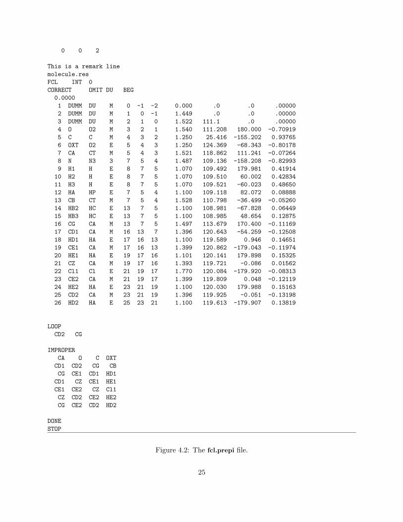
This generates many files, but the only output file that we need is fcl.prepi which contains theatom types and charges for the FCL molecule. Since Antechamber was called with -fo prepi
and -at amber, the fcl.prepi file is in the correct format for input into OSPREY. The contentsof the fcl.prepi may look like Fig. 4.2. All lines from fcl.prepi, between This is a remark line
and DONE (inclusive) must be added between the last DONE line and the STOP line in theall nuc94 and gr.in file. This will allow OSPREY to read in the force field parameters for the FCLmolecule.
As is the case in this example, adding new parameters to all nuc94 and gr.in may also requireadding new parameters to parm96a.dat. FCL has a chlorine atom, Cl. The atom type Cl is notavailable in the original parm96a.dat, and neither are any of the force field parameters related tothis atom type. To obtain these parameters, the parmchk command from the Amber distributioncan be called:
parmchk -i fcl.prepi -fi prepi -o fcl.frcmod
This should generate the different force field parameters for the atom types from the fcl.prepi
file, and output these parameters to the fcl.frcmod file. In the current example, it is sufficient toadd two lines to parm96a.dat. First, add the line
Cl 35.450 same as cl, antechamber
to the group of atom types and mass parameters at the beginning of parm96a.dat, immediatelyafter the line
Cs 132.91 cesium
Next, add the line
Cl 1.9480 0.2650 same as cl, antechamber
to the group of vdW parameters at the end of parm96a.dat, immediately after the line
IB 5.0 0.1 solvated ion for vacuum approximation
In some cases, it may also be necessary to add a subset of the dihedral parameters fromfcl.frcmod to parm96a.dat. This will happen if an atom whose atom type is not available inthe original parm96a.dat is also part of a dihedral whose two central atoms define a rotatablebond, as determined by the rotamers for the given molecule (see Sec. 4.2).
The eef1parm.dat file
The eef1parm.dat file contains solvation energy parameters for different force field atom types,as described in [21]. The mapping between amino acid atom names and force field atom typesis done in the EEF1.java class, so any changes to the eef1parm.dat file should also be reflectedin EEF1.java. The eef1parm.dat file only contains parameters for proteins (e.g., there are noparameters for phosphorus); cofactors and ligands that are not natural amino acids are not includedin the solvation energy computation.
24
0 0 2
This is a remark line
molecule.res
FCL INT 0
CORRECT OMIT DU BEG
0.0000
1 DUMM DU M 0 -1 -2 0.000 .0 .0 .00000
2 DUMM DU M 1 0 -1 1.449 .0 .0 .00000
3 DUMM DU M 2 1 0 1.522 111.1 .0 .00000
4 O O2 M 3 2 1 1.540 111.208 180.000 -0.70919
5 C C M 4 3 2 1.250 25.416 -155.202 0.93765
6 OXT O2 E 5 4 3 1.250 124.369 -68.343 -0.80178
7 CA CT M 5 4 3 1.521 118.862 111.241 -0.07264
8 N N3 3 7 5 4 1.487 109.136 -158.208 -0.82993
9 H1 H E 8 7 5 1.070 109.492 179.981 0.41914
10 H2 H E 8 7 5 1.070 109.510 60.002 0.42834
11 H3 H E 8 7 5 1.070 109.521 -60.023 0.48650
12 HA HP E 7 5 4 1.100 109.118 82.072 0.08888
13 CB CT M 7 5 4 1.528 110.798 -36.499 -0.05260
14 HB2 HC E 13 7 5 1.100 108.981 -67.828 0.06449
15 HB3 HC E 13 7 5 1.100 108.985 48.654 0.12875
16 CG CA M 13 7 5 1.497 113.679 170.400 -0.11169
17 CD1 CA M 16 13 7 1.396 120.643 -54.259 -0.12508
18 HD1 HA E 17 16 13 1.100 119.589 0.946 0.14651
19 CE1 CA M 17 16 13 1.399 120.862 -179.043 -0.11974
20 HE1 HA E 19 17 16 1.101 120.141 179.898 0.15325
21 CZ CA M 19 17 16 1.393 119.721 -0.086 0.01562
22 Cl1 Cl E 21 19 17 1.770 120.084 -179.920 -0.08313
23 CE2 CA M 21 19 17 1.399 119.809 0.048 -0.12119
24 HE2 HA E 23 21 19 1.100 120.030 179.988 0.15163
25 CD2 CA M 23 21 19 1.396 119.925 -0.051 -0.13198
26 HD2 HA E 25 23 21 1.100 119.613 -179.907 0.13819
LOOP
CD2 CG
IMPROPER
CA O C OXT
CD1 CD2 CG CB
CG CE1 CD1 HD1
CD1 CZ CE1 HE1
CE1 CE2 CZ Cl1
CZ CD2 CE2 HE2
CG CE2 CD2 HD2
DONE
STOP
Figure 4.2: The fcl.prepi file.
25

User control of the energy function
The user is also allowed to change certain energy function parameters, such as the value of thedielectric constant and the scaling factor for the vdW radii of the atoms, from the KStar.cfgconfiguration file. For details, see Sec. 3.2.3.
4.4 Perturbations
DEEPer calculations [18], whether GMEC- or K∗-based, require a perturbation file, which specifiesthe modes of flexibility other than sidechain dihedral changes that are available to the molecule.This file contains a list of perturbations (i.e., modes of flexibility), followed by a list of residues andthe residue conformations (RCs) available to them (see [18] for a description of these concepts).Perturbation files can be generated automatically by the new perturbation selection module, de-scribed in [18]. So for many applications, the user will not need to work with the perturbation file(the selection module will generate it, and then OSPREY will read it for use in the design run).In some cases, the user may want to generate some perturbations by hand, or may otherwise wantto specify a set of perturbations differing from what would be automatically generated. Theseperturbations can be provided in a “starting perturbation file.” The selection module can eitheradd these perturbations to the automatically generated perturbations or use only the perturba-tions provided in the starting perturbation file, depending on the user’s choice. Also, the user canspecify a set of parameter intervals to be used for all shears and backrubs. Options for configuringthe residue-conformation selection mechanism are also provided. All these options are describedin section 5.1.1. The user can also write or change the set of RCs specified in the perturbationfile, if these need to be different from what the automatic selection module would generate fromthe specified perturbations. However, this is expected to rarely be necessary, since the automaticselection module is configured to handle most reasonable options for generating RCs from a set ofperturbations.
Perturbation files consist of two parts. We will now describe each part and give examples.The first part gives information on the perturbations themselves. This part is more likely to
require user modification. It starts with a line giving the title of the file (this is PERTURBATIONS
by default), and then a line stating the number of perturbations, as follows:
PERTURBATIONS
8
This is followed by a list of the perturbations, in the order in which they should be applied. Therecord for each perturbation starts with a line naming the perturbation type: BACKRUB, SHEAR,LOOP CLOSURE ADJUSTMENT, SSNE, SSCE, PARTIAL STRUCTURE SWITCH, FULL
STRUCTURE SWITCH, or PROLINE FLIP. These type of perturbations are explained in [18],except that secondary structure adjustments [18] should be listed as either LOOP CLOSURE
ADJUSTMENT, if they affect only three residues (and thus are formally the same as a loopclosure adjustment); SSNE (Secondary Structure N-terminal Extension), if they are expanding asecondary structure element (helix or strand) at its N-terminus; or SSCE (Secondary StructureC-terminal Extension), if they are expanding a secondary structure element at its C-terminus. Thenext line states the residue numbers for the residue affected by the perturbation (using the PDB-file-based numbering system for residues). The next line says n states where n is the number of “states”
26

available to the perturbation (each corresponds to an interval for the perturbation parameter). Thestates are then listed, one to a line, in the format u v where the parameter (denoted as x) is in therange u ≤ x ≤ v for that interval. The first state should be unperturbed, meaning u+ v = 0 (i.e.,the state is centered at the starting backbone conformation). An example record for a backrubperturbation is shown here:
BACKRUB
36 37 38
2 states
-2.0 2.0
2.0 5.0
This backrub affects residues 36-38 and has 2 states, one for which −2 ≤ x ≤ 2 and one forwhich 2 ≤ x ≤ 5 (where x is the backrub parameter).
The second part of the perturbation file defines the perturbed residue conformations for eachaffected residue. (Perturbed residue conformations are those that correspond to a perturbed param-eter interval for some perturbation). This part of the file is unlikely to requires user modification.The record for each residue starts with a line saying “RES,” followed by a line stating the residuenumber of the residue (PDB-based) and a line of the form m states n RCs. A residue conforma-tion will be represented as the triple of an amino-acid type, a sidechain rotamer, and a “residueperturbation state,” meaning a tuple of intervals corresponding to each perturbation affecting theresidue; the residue will have n perturbed residue conformations and m of these residue perturba-tion states. The next line says PERTURBATIONS followed by the numbers of the perturbationsaffecting the residue (in the order given in the first part of the perturbation file, starting with 0).Then the residue perturbation states are defined, one to a line. Each state is represented usinginterval numbers (in the order given in the first part of the perturbation file, starting with 0) foreach perturbation affecting the residue, separated by spaces. The next line says RCs, and is fol-lowed by a set of lines defining the residue conformations, one to a line, in the format AA TYPE
m n where AA TYPE is the amino-acid type, m is the sidechain rotamer number for the residue(numbered as in the rotamer library) and n is the residue perturbation state (in the order listedin this residue record, starting with 0). Unperturbed RCs are not included here; all unperturbedRCs (i.e., all rotamers along with residue perturbation state 0) are assumed to be used for thecalculations. m = −2 denotes the wild-type rotamer.
An example record for a residue is as follows. It describes residue number 65, which is affectedby a single shear perturbation. This shear is the first perturbation described in the first part of theperturbation file (so perturbation number 0 in the 0-based numbering system). The shear has onlyone perturbation state, which is unperturbed (though it allows minimization of the shear parameterin the range from -2.5 to 2.5). As a result, the residue has only one residue perturbation state andonly unperturbed RCs (normal rotamers, in this case allowing up to 2.5◦ of shear minimization ineither direction from the starting backbone):
RES
65
1 states 0 RCs
PERTURBATIONS 0
0
RCs
27
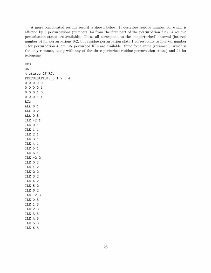
A more complicated residue record is shown below. It describes residue number 36, which isaffected by 5 perturbations (numbers 0-4 from the first part of the perturbation file). 4 residueperturbation states are available. These all correspond to the “unperturbed” interval (intervalnumber 0) for perturbations 0-2, but residue perturbation state 1 corresponds to interval number1 for perturbation 4, etc. 27 perturbed RCs are available: three for alanine (rotamer 0, which isthe only rotamer, along with any of the three perturbed residue perturbation states) and 24 forisoleucine.
RES
36
4 states 27 RCs
PERTURBATIONS 0 1 2 3 4
0 0 0 0 0
0 0 0 0 1
0 0 0 1 0
0 0 0 1 1
RCs
ALA 0 1
ALA 0 2
ALA 0 3
ILE -2 1
ILE 0 1
ILE 1 1
ILE 2 1
ILE 3 1
ILE 4 1
ILE 5 1
ILE 6 1
ILE -2 2
ILE 0 2
ILE 1 2
ILE 2 2
ILE 3 2
ILE 4 2
ILE 5 2
ILE 6 2
ILE -2 3
ILE 0 3
ILE 1 3
ILE 2 3
ILE 3 3
ILE 4 3
ILE 5 3
ILE 6 3
28
Chapter 5
OSPREY Commands
We will assume that the MPI-based or multithreaded OSPREY command (Sec. 3.2) has beenexecuted and the program is waiting for the user to execute one of the available commands. TheOSPREY commands can be divided into three general algorithmic modules, each described in aseparate section of this documentation.
Redesign can be performed using a GMEC-based approach in which candidate protein mutantsare ranked based on the single best conformation (the Global Minimum Energy Conformation,GMEC) for each candidate mutant. The OSPREY GMEC-based redesign approach utilizes anumber of Dead-End Elimination (DEE) algorithms combined with the A∗ search algorithm forsolving protein redesign problems. GMEC-based redesign with OSPREY is described in Sec. 5.1.
Alternatively, redesign can be performed using an ensemble-based approach in which candidatemutants are ranked based on an ensemble of low-energy conformations, rather than just the GMEC.The OSPREY ensemble-based approach utilizes the K∗ algorithm for protein-ligand binding pre-diction and protein redesign. Redesign with K∗ is described in Sec. 5.2.
Finally, OSPREY allows the user to use a Self-Consistent Mean Field (SCMF)-based algorithmfor computing residue entropies for all residue positions in a protein. This algorithm can be usedin combination with a DEE-based algorithm to predict mutations anywhere in a protein. Sucha hybrid SCMF/DEE approach is applicable to, e.g., enzyme redesign for improving the targetsubstrate specificity of the mutant enzymes. The SCMF computation in OSPREY is described inSec. 5.3.
Once the execution of a OSPREY command completes, OSPREY exits. If more OSPREYcommands must be executed, the mpirun or java command must be executed again, followed bythe desired OSPREY command.
NOTE: The mpirun/java and the OSPREY commands need not be executed sequentially;rather, these commands can be executed as a single command. For example, the doDEE command(described in Sec. 5.1) can be executed in the following way:
mpirun -machinefile ./machines -np 5 java -Xmx1024M KStar mpi -c KStar.cfg doDEE
System.cfg DEE.cfg
or
java -Xmx1024M KStar -t 5 -c KStar.cfg doDEE System.cfg DEE.cfg
With any of these single command, the standard output from OSPREY can be redirected to a
29

file for analysis. For example, assuming tcsh is used:
mpirun -machinefile ./machines -np 5 java -Xmx1024M KStar mpi -c KStar.cfg doDEE
System.cfg DEE.cfg >! logDEE.out
This command will generate a file logDEE.out that will store all standard output from theOSPREY run. This way, some advanced information (such as rotamer pruning and detailed runningtimes) that is typically not generated as part of the standard OSPREY output files, will be availablefor analysis by the user. NOTE: For some problems, the standard output from a OSPREY runmay generate very large files (sometimes, though rarely, exceeding 1GB), so the user should makesure that there is sufficient space in the target location.
30

5.1 GMEC-based Redesign
The GMEC-based redesign uses DEE-based rotamer pruning and A∗ conformation enumeration.The DEE pruning stage can incorporate continuously-flexible rotamers (the MinDEE algorithm [15]or the more efficient iMinDEE algorithm [11]) or continuous (the BD algorithm [12]) or discrete (theBrdee algorithm [13]) protein backbones. Traditional DEE pruning [8, 27] for a rigid backboneand rigid rotamers can also be performed.
In a GMEC-based redesign, mutation sequences are ranked according to the single lowest-energyrotamer-based conformation for each sequence. Typically, either only the overall GMEC (over allmutation sequences) is identified, or a gap-free list of conformations and sequences is generated, suchthat all conformations/sequences within a user-specified energy window from the GMEC energyare generated by the A∗ enumeration [15].
A GMEC-based mutation search can be performed by OSPREY using the following command:
doDEE System.cfg DEE.cfg
The System.cfg and DEE.cfg configuration files are described in detail below (Sec. 5.1.1). Thenames of the two configuration files specified after the doDEE command can be chosen by the user;for clarity, we will refer to these files as System.cfg and DEE.cfg throughout this documentation.The output of the doDEE command is also described below (Sec. 5.1.2).
Once the doDEE command completes its execution, the user will have a list of low-energyconformations and sequences. PDB structures for selected conformations can then be generatedusing the following command:
genStructDEE System.cfg GenStruct.cfg
The System.cfg configuration file is the same as with the doDEE command. The GenStruct.cfg
file (or the corresponding user-specified filename) is described in detail in Sec. 5.1.1 below. Theoutput of the genStructDEE command is described in Sec. 5.1.2 below. The genStructDEE
command is executed on a single processor.The GMEC-based mutation search can be applied with or without the DACS (Divide-And-
Conquer Splitting) algorithm [14]. DACS divides the conformation space into non-overlappingpartitions and uses partition-specific information to efficiently generate the GMEC for each parti-tion. The partition GMEC’s are then used to obtain the overall GMEC, for the full conformationspace. DACS was found to result in speedups of up to more than three orders of magnitude whencompared to DEE/A∗ runs without DACS [14]. DACS can be performed on a single processor oron a (large) cluster of processors. Generally, the user can adapt the DACS partitioning schemedepending on the redesign problem and the availability of computational resources.
5.1.1 Configuration Files
System.cfg
This configuration file contains the information about the system (protein) being redesigned. Thefile format has been significantly changed in OSPREY 2.0 to support protein-protein interactions.A minimal file looks like this:
pdbName dhfr_8A_ucp_mod.pdb
31

numOfStrands 1
strand0 3 151
strand1 300 300
strandMutNums 7 1
strandMut0 5 20 31 46 50 54 92
strandMut1 300
strandAA0 true
strandAA1 false
strandRotTrans0 false
strandRotTrans1 true
numCofRes 1
cofMap0 200
grotFile1 GenericRotamers.dat
In addition to the required parameters, the following parameters are required when differentstructures are use for either of the unbound ligands:
UseUnboundStruct0 false
UseUnboundStruct1 false
unboundPdbName0 none
unboundPdbName1 none
A description of the parameters is as follows:
pdbName
The name of the input pdb file of the design system. This should be the file modifiedby the user according to the instructions for making the input structure compatible withOSPREY, as described in Sec. 4.1.
numOfStrands
The number of strands to be designed: 1 or 2. 2 strands are designed when two bindingpartners are being redesigned and it is desirable to have them rotate and translate. Forexample, if a protein-protein interface is being designed, and one of the proteins can translateand rotate a small distance within the active site, then the number of strands is equal to 2.Similarly, if a protein-ligand binding site is being designed, the second strand corresponds tothe ligand. If, by contrast, only one protein is being designed, or no rotation/translation isdesired in a GMEC-based design, then the number of strands is 1.
strand0
The range of residues for strand0. For example, if strand0 is defined from residue 1 toresidue 90, the value would be ‘1 90’. NOTE: residue numbers are assumed to be consecutive;there is no notion of ’chains’ in OSPREY. The user should therefore renumber residues thatare in different chains so that no two residues have the same number in the PDB file.
strand1
32

The range of residues for strand1, if two strands are defined. For example, if strand1is defined from residue 91 to residue 120, the value would be ‘91 120’. If a strand is only oneresidue long that residue should be listed as both the start and end of the strand. I.E. if theligand is residue 300 then “strand1 300 300” should be used.
strandMutNums
The number of flexible/mutable residues in each strand. For example, ‘4 6’ specifies 4flexible/mutable residues in strand 0 and 6 flexible/mutable residues in strand 1.
strandMut0
The list of residue numbers (numbering from PDB file) that can mutate in strand0,separated by a space. For example ‘2 3 15 20’. The total number of residues must agree withthe first field in strandMutNums.
strandMut1
The list of residue numbers (numbering from PDB file) that can mutate in strand1,separated by a space. For example ‘91 92 100’. The total number of residues must agree withthe second field in strandMutNums.
strandAA0/strandAA1
Is strandi composed of Amino acids? If so, set strandAAi to true, otherwise to false.
strandRotTrans0
True/false flag that determines whether this strand can perform rigid-body motions ofrotation and translation. Note that only one strand (the smaller of the two strands) needs tobe set to rotate and translate since it is redundant for both to rotate and translate.
strandRotTrans1
True/false flag that determines whether this strand can perform rigid-body motions ofrotation and translation.
onlySingleStrand
Integer flag that determines if only one strand will be present during the design. Thisflag is used for DEE runs where the user would only like to design one of the protein strandsinstead of the complex. Set value to the strand number to be designed. I.E. if you would liketo design only strand 1 then set the value of onlySingleStrand to “1”. If you want to designthe protein complex choose “-1” (default is -1).
useUnboundStruct0
Determines if a different unbound structure for strand0 is used for the unbound partitionfunction computation. By default, K∗ uses the input structure for the bound protein-ligandcomplex (specified by the pdbName parameter in the System.cfg file described in Sec. 5.1.1)for both the bound and unbound (free protein) partition function computation. In the defaultcase, the unbound (free) protein structure is obtained by simply removing the ligand from
33

the input structure. This approach is useful if only a bound protein-ligand structure isavailable. In cases where a structure of the free protein is also available, that structure can beused for the unbound partition function computation; the useUnboundStruct parametershould then be set to true. NOTE: If both the bound and unbound structures are used, theonly difference between these structures should be the conformation of the residues in thesestructures and the lack of a ligand in the unbound structure; the two structures must havethe same input residues (e.g., if residue 278 is present in the bound structure, it must also bepresent in the unbound structure, and vice versa).
useUnboundStruct1
Same as useUnboundStruct0, but for strand1.
unboundPdbName0
The name of the input pdb file for the unbound (free) protein defined in strand0. Thisshould be the file modified by the user according to the instructions for making the inputstructure compatible with OSPREY, as described in Sec. 4.1. This parameter is only takeninto account if useUnboundStruct is true.
unboundPdbName1
Same as unboundPdbName0, but for strand1.
minEnergyMatrixNameUnbound0/maxEnergyMatrixNameUnbound0
The precomputed lower-/upper-bound pairwise energy matrix file names for the un-bound (free) protein structures. These matrices are analogous to the minEnergyMatrix-Name and maxEnergyMatrixName matrices, which are used for the bound protein-ligandcomputation (or for both the bound and unbound computation if unboundPdbName0is false). The minEnergyMatrixNameUnbound0 and maxEnergyMatrixNameUn-bound0 parameters are only taken into account if unboundPdbName0 is true.
minEnergyMatrixNameUnbound1/maxEnergyMatrixNameUnbound1
Same as minEnergyMatrixNameUnbound0/maxEnergyMatrixNameUnbound0,but for strand1.
grotFile
The file that contains the rotamer library data for general compounds (see Sec. 4.2).
cofMap0
The pdb residue numbers for all cofactors in strand 0. If there are no cofactors eitherdon’t include the flag or set the value to -1.
cofMap1 Same as cofMap0 but for strand 1.
34

DEE.cfg
This configuration file contains the information about the DEE/A∗ mutation search parameters.A minimal file looks like this:
runName dhfr-dee-example
addWT false
resAllowed0_0 leu
resAllowed0_1 leu
resAllowed0_2 val
resAllowed0_3 thr
resAllowed0_4 ile
resAllowed0_5 leu
resAllowed0_6 phe ile
resAllowed1_0 drg
The above example sets a DEE/A* search with 7 flexible residues in the protein, and a ligand.One residue, phe92 is allowed to undertake one of two identities: phe or ile. In addition to theseparameters, the following parameters have default values assigned, shown here, and can be modifiedby the user:
numMaxMut 1000
algOption 3
imindee false
ival 0.5
doDACS false
splitFlags false
distrDACS false
doMinimize false
minimizeBB false
doBackrubs false
backrubFile none
minEnergyMatrixName runNameminM.dat
maxEnergyMatrixName runNamemaxM.dat
useEref true
initEw 0.0
pruningE 100.0
stericE 30.0
approxMinGMEC false
lambda 0.0
preprocPairs true
pairSt 100.0
scaleInt false
maxIntScale 0
minRatioDiff 0.15
initDepth 1
subDepth 1
35

diffFact 6
genInteractionGraph false
distCutoff 10000.0
eInteractionCutoff 0.0
outputConfInfo c_runName_
outputPruneInfo p_runName_
addWT true
typedep false
onlysinglestrand -1
resumeSearch false
resumeFilename runInfo.out.partial
useTriples false
magicBulletTriples true
magicBulletNumTriples 5
useFlagsAStar false
doPerturbations false
perturbationScreen false
perturbationFile defaultPerturbationFileName.pert
minimizePerturbations false
screenOutFile screenOutFileDefaultName.pert
idealizeSidechains true
selectPerturbations false
minRMSD 0
shearParams -2.5 2.5
backrubParams -2.5 2.5
RamachandranCutoff 0.02
startingPerturbationFile none
onlyStartingPerturbations false
addWTRots false
UseCCD true
MinimizePairwise true
UseEPIC false
checkEPIC false
EPICThresh1 10
EPICThresh2 25
EnforceEPICThresh true
EPICGoalResid 0.0001
EPICUseSVE true
EPICUsePC true
MinPartialConfs true
A description of the parameters, both optional and required, is as follows:
runName
The file in which partial results are stored. The format of this file is described in detailin Sec. 5.1.2. This parameter is required.
36

numMaxMut
The maximum number of mutations from the wildtype, such that any solution generatedby the algorithm will contain not more than numMaxMut mutations. By default a verylarge number, 10000, is used here. If you wish to limit the number of simultaneous mutationsto, for example, two residue positions, then set a 2 here.
algOption
Determines the types of DEE criteria applied: 2-split positions DEE is used for algOption>=2,while DEE pairs pruning is applied for algOption>=3. The other DEE criteria (Bounds,simple Goldstein, 1-split position DEE) are used for any value of algOption. See [14] for areview of the different DEE pruning criteria. By default, a value of 3 is used.
imindee
If continuous side-chain minimization is used, the iMinDEE algorithm can dramaticallyincrease the amount of pruning that is performed before the A* conformational search. Indesign problems where the size of the conformational space is large, this can be critical [11].By default it is false. Set to true to use it.
ival iMinDEE performs a “greedy” round of pruning on its first iteration that dependson an initial tight pruning value. We have performed many effective tests with a value of 0.5for ival. This pruning value is called I0 in [11], where it is thoroughly explained.
doDACS
Determines if the algorithms should use DACS or not. If false, then DACS is not per-formed after the initial DEE pruning and the program directly proceeds to a single-processorA∗ conformation enumeration; otherwise, DACS splitting is performed. By default it is setto false
splitFlags
Is the split-flags technique used? See [14] for a review of this pruning algorithm. Bydefault it is set to true.
distrDACS
Will the DACS run be distributed? If true, then each DACS partition is distributed toa separate processor for evaluation. If there are more partitions than processors, a queue isformed and the distribution continues until there are no remaining partitions in the queue.If distrDACS is false, the DACS partitions are evaluated sequentially on a single processor.By default it is set to false.
doMinimize
Determines if energy minimization is to be performed; true if energy minimization isperformed (for Brdee, BD, MinDEE); false otherwise (for traditional DEE). By default it isset to false
37

minimizeBB
Determines if backbone energy minimization is to be performed; true if backbone en-ergy minimization is performed (for BD and Brdee); false otherwise (for MinDEE). Thisparameter is taken into account only if doMinimize is true. By default it is set to false
doBackrubs
Determines if backrubs are to be performed; true if backrubs are performed (for Brdee);false otherwise (for BD). This parameter is taken into account only if minimizeBB is true.By default it is set to false
backrubFile
The input file that contains the precomputed allowed backrub sets (this is the outputfile from the precomputeBackrubs command described in Sec. 5.1.4). This parameter istaken into account only if doBackrubs is true.
minEnergyMatrixName/maxEnergyMatrixName
The precomputed lower-/upper-bound pairwise energy matrix file names. For tradi-tional DEE, where no minimization is performed, only the min matrix is computed andstored. These matrices are described in detail in Sec. 5.1.2. As of version 2.0 this parameterhas a default value based on the runName. It is therefore recommended that the user notchange it.
useEref
Determines if amino acid reference energies are used as part of the energy function. Theamino acid reference energies are computed using the lowest computed intra-rotamer energyfor each amino acid type among all flexible residue positions (similarly to [24]). By defaultthis is set to true.
initEw
The Ew value [15] used to guarantee that no conformations having an energy within Ewof the energy of the GMEC are pruned by the DEE algorithms. The value of initEw is alsoused as a halting condition to determine the set of conformations generated by A∗. If initEwis set to zero, then the only conformation that is guaranteed not to be pruned is the GMEC.Larger values of initEw can generate a gap-free list of multiple low-energy conformationsand mutation sequences. By default this is set to 0.
pruningE
Conformations with an energy lower bound greater than this value are pruned. Thisparameter is used by the MinBounds algorithm [14]. A value for this parameter can begenerated using the doSinglePartFn command (Sec. 5.2) and setting pruningE to be theenergy of the lowest-energy conformation for the wildtype protein sequence. If the value ofpruningE is not obtained through doSinglePartFn, then pruningE can be conservativelyset to a reasonably large value (e.g., 50-100 kcal/mol), so that conformations with high energybounds are pruned. By default this is set to 100.0.
38
stericE
Rotamers with intra-rotamer plus rotamer-to-template energy greater than this thresh-old are pruned as a preprocessing step. By default this is set to 30.0.
approxMinGMEC
Determines if the heuristic halting condition for the DEE/A∗ computation should beused (see [3, Supporting Information, Sec. S1.2.3]); true if the heuristic halting condition isused; false if the provable halting condition (see [15, Proposition 2]) is used. The heuristichalting condition is useful for DEE algorithms that use minimization (MinDEE, BD, andBrdee), since these algorithms require the A∗ enumeration of a significantly larger numberof conformations before the mutation search can be provably halted.
lambda
The cutoff for the heuristic halting condition; lambda is only used if approxMinG-MEC is true. Let bm be the computed lower bound on the conformational energy of thefirst rotameric conformation generated by A∗, and let bc be the computed lower bound on theconformational energy of the current rotameric conformation generated by A∗. The DEE/A∗
search can then be halted when bc > bm + λ. By default this is set to 0.
preprocPairs
Determines if rotamer pairs should be pruned based on a steric energy threshold: trueif rotamer pairs should be pruned based on a steric energy threshold; false otherwise. Bydefault this is set to true.
pairSt
If preprocPairs is true, rotamer pairs with interaction energy greater than this thresh-old are pruned as a preprocessing step. This parameter is analogous to the stericE parameterfor single rotamers. By default this is set to 100.0.
scaleInt
This parameter scales down the E� pairwise energy interval terms (see [12, Eq. 9]) toallow for additional rotamer pruning. It is recommended to keep this parameter set to falsesince the effects of applying interval scaling are not yet fully evaluated. By default this is setto false.
maxIntScale
The maximum scaling factor (0-1) for the interval terms (if scaleInt is true). The valueof this scaling factor decreases as a function of the distance between the respective residuepositions involved for each interval term.
minRatioDiff
This is a parameter that is used for choosing a major split position for the DACSalgorithm, in combination with the original p-ratio approach. The higher the value, the morefavored lower-numbered residue positions are (see [14] for details). Faster run times were
39

achieved with a value of 0.15 as compared to a value of 0.0, although optimization of thisparameter has not been attempted.
initDepth
This parameter is only used if distrDACS is true. initDepth determines the numberof major splitting positions for the DACS algorithm. DACS partitions are formed by enu-merating all combinations of unpruned rotamers for each residue position (each combinationis given by a single rotamer choice for each residue position). For example, if initDepth is 2and each of the two selected major split positions has q rotamers, then there will be q2 DACSpartitions. Each partition is then distributed to a separate processor for evaluation. Harderproblems may require larger values of initDepth (depending on the processor availability).However, if the value of initDepth is too large (e.g., close to numInAS, the total numberof flexible residue positions), the partition enumeration may come at a significant additionalcomputational cost. The initDepth partitioning will be referred to as major partitioning.
subDepth
This parameter is used when doDACS is true and (1) distrDACS is false, or (2) dis-trDACS is true and the current major partition has already been distributed for computationto a given processor. The value of subDepth gives the number of (additional) minor splittingpositions. Partitions (rotamer combinations) are formed the same way as with initDepth.The difference from initDepth is that the newly-formed partitions are evaluated sequentiallyon the current processor, and not distributed to separate processors. If the sum of initDepthand subDepth is too large (e.g., close to numInAS), the partition enumeration may comeat a significant additional computational cost. The subDepth partitioning will be referredto as sub-partitioning.
diffFact
Consider a given major partition for evaluation (or the single initial partition, if dis-trDACS is false). Also, note that sub-partitioning is implemented as a recursive procedurein OSPREY. Let i < subDepth be the current residue position, such that the current sub-partition (combination of rotamers) is only assigned for i of the minor splitting positions.If the total number of remaining unpruned conformations for the current partially-assignedpartition is not more than 10diffFact, then the sub-partitioning is stopped and A∗ enumera-tion for the current partially-assigned partition is executed. Otherwise, the sub-partitioningis continued until either the diffFact stopping condition is reached, or all minor splittingpositions are assigned, at which point the A∗ enumeration is executed.
genInteractionGraph, distCutoff, eInteractionCutoff
The genInteractionGraph parameter must be set to false. genInteractionGraph,distCutoff, and eInteractionCutoff are used for residue interaction graph generation,rather than conformation/sequence generation, and are thus not applicable here.
outputConfInfo
The output file name that will store information about the best-energy conformationsfound. If distrDACS is true, a directory named conf info must exist in the source code
40

directory, since this is where the output files will be stored. These output files are discussedin detail in Sec. 5.1.2.
outputPruneInfo
The output file name that will store information about the pruning done. If distrDACSis true, a directory named conf info must exist in the source code directory, since this is wherethe output files will be stored. These output files are discussed in detail in Sec. 5.1.2.
onlySingleStrand
If the System.cfg defines more than one strand, it might be desirable to compute theGMEC using DEE/A* of only one strand. If the desired strand is strand0, then onlySin-gleStrand should be set to 0. If the desired strand is strand1, then onlySingleStrand shouldbe set to 1. If, instead, the target is the GMEC of the complex then onlySingleStrand shouldbe set to -1. By default onlySingleStrand is set to -1.
addWT
Determines if the redesign positions should be allowed to keep their wildtype identity,in addition to allowing them to mutate to the amino acid types in resAllowedi (see below).By default this is set to true. If set to true, residues that are not explicitly listed in DEE.cfgare assumed to be flexible but not mutable.
resAllowedj i
What amino acid types are allowed for the j-th strand’s i-th flexible residue (numberedfrom 0, 1, ..., strandMutNums[j])? Use standard three-letter amino acid codes separatedby a single space. If for a given residue position k, only the wildtype should be allowed, setaddWT to true, and leave resAllowedj empty (however, a single empty space must stillbe present immediately after resAllowedk). As of version 2.0, the user can omit entriesfor specific postions; OSPREY will assume that these omitted entries are flexible but notmutable and that the wildtype must be preserved there.
resumeSearch
Is the current run an unfinished search, so that the resume files must be loaded? Thisis used only to resume a distributed DACS run, so that the completed partitions will not haveto be computed again. The resume capability is discussed in detail in Sec. 5.1.2. By defaultthis is set to false.
resumeFileName
What file contains the resume information if resumeSearch is set to true?
useTriples
Should we try to prune triples of rotamers? Any triple of rotamers at different residuesis considered for pruning, using a criterion analogous to the simple Goldstein rotamer pruningand the DEE pairs pruning described above. By default this is set to false.
41

magicBulletTriples
If pruning triples, should we try to prune them only using competitor triples that appearlikely to be most effective for pruning (using a heuristic “magic-bullet” competitor-selectioncondition based on that of [16] for pairs)? By default this is set to true.
magicBulletNumTriples
If magicBulletTriples is set to true, how many competitor triples should we try whenattempting to prune each candidate triple? By default this is set to 5.
useFlagsAStar
When expanding the A∗tree, should we avoid forming nodes that contain pruned pairsor triples of rotamers? By default this is set to false.
doPerturbations
Should DEEPer be used (in other words, should we allow flexibility in the form ofperturbations)? By default this is set to false.
perturbationFile
If this is a DEEPer run, what is the name of the perturbation file to use? If selectPer-turbations is set to true, this file will be generated by the automatic perturbation selectionmodule; otherwise it needs to be provided by the user. The file follows the format describedin section 4.4. By default this is set to “defaultPerturbationFileName.pert”.
perturbationScreen
If this is a DEEPer run, should the program only proceed through the pruning phase,and then produce a record of what was pruned, in order to help with perturbation selection?By default this is set to false.
minimizePerturbations
If running DEEPer, should perturbations be allowed continuous flexibility? (If not,then for every parameter interval specified in the perturbation file, only the mean value forthe interval will be allowed). By default this is set to false.
idealizeSidechains
If running DEEPer, should sidechains for residues affected by perturbations be movedas rigid bodies to attain ideal Cβ geometry, as in KiNG [20]? (Turning this feature off mayproduce unrealistic sidechain conformations, particularly for large perturbations). By defaultthis is set to true.
addWTRots
If set to true then the wild-type rotamers of the redesigned amino acids in the structureare added to the search. Only the wild-type rotamers of the amino acids that are defined inthe System.cfg file as mutable will be added. If running DEEPer, they will be added to thespecific residues in the structure at which they appear; if not, then they will be added to the
42
rotamer library for all residue positions, since variable rotamer sets for amino acids of thesame type are not supported outside DEEPer. By default this is set to false.
screenOutFile
If pertScreen is true, what should the output file be? (This will be a version of theperturbation file with P’s marked on all pruned residue conformations as well as perturba-tions states for which all residue conformations are pruned and perturbations for which allperturbed states are pruned). By default this is set to “screenOutFileDefaultName.pert”.
selectPerturbations
If running DEEPer, should perturbations be selected using the automatic perturbationselection module? (The following 6 options are used to configure the selection module, andthus are only meaningful if automatic perturbation selection is being used). By default thisis set to false.
minRMSD
A perturbed backbone conformation (and its associated residue conformations) will berejected by the selector if it is too similar to another backbone conformation that is beingconsidered, as measured by backbone heavy-atom RMSD. This RMSD filter can widen thediversity of sampled backbone conformations per unit computational cost. (If minRMSD isset to 0 then the RMSD filter is not used). By default this is set to 0.
shearParams
Sets the parameter intervals to be used for shears. It should be in the format u1 v1 u2v2 ... un vn, where there are n intervals and interval i correspond to ui ≤ θ ≤ vi, where θis the shear parameter. Values should be specified in degrees. By default there is 1 interval,with −2.5◦ ≤ θ ≤ 2.5◦. (This corresponds to a setting of “-2.5 2.5”).
backrubParams
Sets the backrub parameters; same format as shearParams with same default.
RamachandranCutoff
Indicates the cutoff for Ramachandran density to use when selecting perturbed back-bone states; the density on the Ramachandran map must be greater than the cutoff for aperturbed backbone state to be allowed. (The files with density data can be specified inKStar.cfg; see section 3.2.3). By default this is set to 0.02.
startingPerturbationFile
If a value other than the default “none” is provided for this parameter, then the filewith the given name will be read and its perturbations included in the perturbation file forthe calculation. The calculation can be run with only these perturbations, or with theseperturbations plus all the perturbations that the automatic perturbation selection modulegenerates (depending on how onlyStartingPerturbations is set). The input file shouldbe in the format for a perturbation file (section 4.4) except without the section on residue
43

conformations (just the list of perturbations with their information). This option can beuseful for introducing perturbations based on other structures, such as partial or full structureswitches, or for placing perturbations in locations where the automatic perturbation selectorwould not place them (such as shears outside helices).
onlyStartingPerturbations false
Should the calculation be run with only the perturbations in the starting perturbationfile (limiting the automatic selection to selecting RCs for these perturbations)? If not, then theautomatic perturbation selection module will be run normally, and then the perturbationsfrom the starting perturbation file will be added to the perturbations generated by thatmodule. By default this is set to false.
UseCCD true
Indicates that a new, faster CCD (cyclic coordinate descent) minimizer should be used.
minimizePairwise true
Indicates that minimum pairwise energies should be precomputed without the heuristicthat we minimize the full energy of the residue pair, and then subtract off intra energies. Thisheuristic saves time but is not provable, so it is turned off by default.
UseEPIC false
Indicates that the EPIC algorithm should be used to accelerate modeling of continuousflexibility. The following 8 options are only meaningful when EPIC is being used.
CheckEPIC false
Indicates that minimized energy calculations using EPIC for top conformations shouldbe checked using the full energy function and outputted.
EPICThresh1 10
This threshold, also known as b1, is the range of energies over which EPIC is expectedto closely approximate the full energy function. (So when set to 10, EPIC will closely ap-proximate the full energy function for each rotamer pair, for all energies within 10 kcal/molof the optimal interaction for that rotamer pair).
EPICThresh2 25
This threshold, also known as b2, is the range of energies over which EPIC is expectedto provide a lower bound to the full energy function.
EnforceEPICThresh true
Indicates that an error should be raised if the specified values EPICThresh1 and EPIC-Thresh2 turn out to be insufficient for provable solving of the problem at hand.
EPICGoalResid 0.0001
When approximating the full energy function, EPIC will aim to surpass this mean-square residual.
44
EPICUseSVE true
EPIC should use Sparse Atom-Pair Energies (SAPE) when appropriate, to speed up itscalculations.
EPICUsePC true
EPIC should use principal components when appropriate, to speed up its calculations.
MinPartialConfs true
EPIC should be used during A* to minimize the energize of partially defined confor-mations, in order to obtain tighter lower bounds and reduce the number of nodes that needto be fully expanded.
GenStruct.cfg
This configuration file contains the information about the structure generation parameters. Atypical minimal file looks like this:
confResFile c_dhfr-dee-example
numResults 5
onlySingleStrand 0
Other parameters with default values include:
outputpdbs true
addOrigRots false
doMinimize false
minimizeBB false
doBackrubs false
backrubfile none
doPerturbations false
perturbationFile defaultPerturbationFileName.pert
minimizePerturbations false
idealizeSidechains true
addWTRots false
The following parameters must have the same value as the respective parameters in the DEE.cfgfile:
doMinimize false
minimizeBB false
doBackrubs false
backrubfile none
onlySingleStrand 0
doPerturbations false
perturbationFile defaultPerturbationFileName.pert
minimizePerturbations false
45

idealizeSidechains true
addWTRots false
The remaining parameters are described as follows:
confResFile
The file that contains the input information, one conformation per line. This file isobtained from the output of the doDEE command. The format of this file is described indetail in Sec. 5.1.2.
numResults
The number of lines in the confResFile file.
outputPDBs
Determines if pdb structures will be generated for each conformation from the con-fResFile file. This parameter is by default set to true.
5.1.2 Output Files
Pairwise Energy Matrices
The doDEE command first computes a lower-bound and an upper-bound pairwise energy matrix(in the case of MinDEE, BD, and Brdee) or a single matrix (in the case of traditional DEE).These matrices contain the computed interaction energies for the protein template (the proteinbackbone and the side-chains not modeled as flexible), between each rotamer for each residueposition and the protein template, and between each pair of rotamers for the different pairs ofresidue positions. Only the energies for the amino acid types (and the corresponding rotamers)specified by the resAllowedi parameters are computed. For example, in the DEE.cfg sample fileshown in Sec. 5.1.1, resAllowed4 has gly ala cys as the allowed amino acid types (we will assumethat the wildtype identity at that residue position is Ala). In that case, energies involving, e.g.,Leu rotamers at that residue position will not be computed.
In the case of MinDEE, BD, and Brdee, energy minimization (either rotamer or backbone) isallowed. As a result, the energies between rotamer pairs (and between rotamers and the proteintemplate) are not rigid and will depend on the rotamer identities and conformation of the surround-ing residues (see [15, Fig. 2]). If the energy minimization of the rotamers or the protein backbone isrestrained (by, e.g., restraints on the side-chain dihedral movement), then both a lower-bound andan upper-bound for each pairwise energy can be computed within the specified restraints. Hence,the computed lower/upper energy bounds are saved into two matrices. These matrices are savedas binary files, as specified by the minEnergyMatrixName/maxEnergyMatrixName param-eters in the DEE.cfg file. The two energy matrices are used by MinDEE, BD, and Brdee duringthe respective DEE pruning stage. The lower-bound matrix is further used during the A∗ enumera-tion stage to generate conformations in order of increasing lower bounds on their energies [15]. Fortraditional DEE, a single matrix (specified by the minEnergyMatrixName parameter) is com-puted and saved since energy minimization is not allowed. Once the energy matrices are computed,doDEE can read them in every time the DEE/A∗ search is restarted, and the computation of thesematrices need not be repeated, as long as the input structure and allowed mutations (specified bythe resAllowedi parameters) remain unchanged.
46

In DEEPer runs, the pairwise energy matrices are handled the same way except that the energiesare between residue conformation pairs [18] instead of rotamer pairs.
Mutation Search Results
After the computation of the pairwise energy matrices is done, the program moves to the DEEpruning stage, followed by the A∗ enumeration stage. If the DACS algorithm is applied (doDACSin DEE.cfg is set to true), DEE pruning is first applied for the entire conformation space, until nomore dead-ending rotamers/pairs can be identified. The pruning and enumeration stages are thenapplied separately for each of the DACS partitions. Depending on whether DACS is applied andwhether DACS is performed as a distributed run, different files are generated during the mutationsearch.
Mutation search on a single processor (with or without DACS)
Conformation File. Two different types of mutation search are discussed here: DEE/A∗ withoutDACS (doDACS is false), and DACS on a single processor (doDACS is true and distrDACS isfalse). In these cases, one conformation output file, specified by the outputConfInfo parameter inDEE.cfg is generated during the mutation search. This file contains all conformations generatedby A∗ and within the specified energy window (the initEw parameter) from the energy of therespective GMEC. NOTE: No structures are saved during this part of the program execution;rather, only the conformation data necessary to generate the structures is saved, along with therespective computed conformational energies.
Each line in the conformation file corresponds to a single rotamer-based conformation generatedby A∗. The format of each line is as follows:
c a1 a2 . . .an aL r1 r2 . . . rn rL unMinE: eu minE: em minBound: emb bestE: eb
Here, c is the conformation number, in the order generated by A∗; if DACS is applied, con-formation numbers are partition-specific, so there might be multiple conformations with the sameconformation number (but that are part of different partitions). ak is the corresponding three-letteramino acid name for the kth of the total of n (where n = numInAS) flexible residue positions; aL
is the three-letter name of the ligand (if present). Similarly, rk is the corresponding rotamer num-ber for the kth flexible residue position; rL is the rotamer number of the ligand (if present). Arotamer number is determined based on the index (starting from 0) of the given rotamer for thegiven amino acid into the input rotamer library. For example, rotamer 3 of Leu corresponds to χangles −85 65 in the LovellRotamer.dat rotamer library (see Sec. 4.2). The value eu represents theconformational energy before minimization (the energy of the conformation for a rigid backboneand rigid rotamers). The value em represents the conformational energy after the respective typeof minimization (backbone or side-chain); if no minimization is allowed, em = eu. ‘minBound: emb’is only present in the output if energy minimization is allowed and represents the computed lowerenergy bound for the current conformation; this lower energy bound is used by A∗ for enumeratingconformations in order. The value eb is the best (lowest) conformational energy found in the A∗
search so far. An example (partial) outputConfInfo file (for seven flexible residue positions, anArg ligand, single-processor DACS, and no minimization) may look like this (lines are wrapped):
1 MET GLY ASP ARG ALA ALA MET ARG 6 0 2 18 0 0 9 31 unMinE: -273.75903 minE:
47

-273.75903 bestE: -273.759032 MET GLY ASP MET ALA ALA MET ARG 6 0 2 6 0 0 9 31 unMinE: -271.96558 minE:
-271.96558 bestE: -273.759033 MET GLY ASP ARG ALA ALA GLY ARG 6 0 2 18 0 0 0 31 unMinE: -271.7832 minE:
-271.7832 bestE: -273.759031 MET ASP SER ARG GLY ALA VAL ARG 6 3 2 18 0 0 1 29 unMinE: -276.5042 minE:
-276.5042 bestE: -276.5042
2 MET ASP SER ARG GLY ALA VAL ARG 6 3 1 18 0 0 1 29 unMinE: -276.4287 minE:
-276.4287 bestE: -276.5042
In DEEPer, residue conformation numbers instead of sidechain rotamer numbers will be listed.However, these will be followed by the words SC rotamers: and then the sidechain rotamerscorresponding to these residue conformations. For example, the first line of the outputConfInfofile may look like this:
1 GLY ILE PRO PRO 0 6 0 0 SC rotamers: 0 5 0 0 unMinE: -81.32703 minE: -82.228836
minBound: -83.52793 bestE: -82.228836
NOTE: In some cases, the conformations stored in the outputConfInfo file can be a supersetof the conformations actually within initEw of the GMEC:
• If energy minimization is allowed (i.e., MinDEE, BD, or Brdee), the set of A∗-generated con-formations may be significantly larger than the set of conformations actually within initEwfrom the GMEC. This is due to the fact that, in the cases with energy minimization, A∗ enu-merates conformations in order of increasing lower bounds on their energies. However, sincedifferent conformations can minimize differently, the order of the lower energy bounds is notnecessarily the same as the order of the conformations when the actual minimized energiesare taken into account [15].
• If DACS is used, then additional conformations whose energy lower bounds are within initEwof the partition-specific GMEC (but not necessarily of the overall GMEC) may also be gen-erated and stored.
NOTE: If approxMinGMEC in DEE.cfg is set to false, then only the conformations withactual energies within initEw of the GMEC (or the partition-specific GMEC) are stored, although alarger number of conformations may be generated by A∗. If approxMinGMEC is set to true, thenall conformations generated by A∗ are stored, independent of the actual energies. Since approx-MinGMEC is also used as a heuristic halting condition for the DEE/A∗ search (see Sec. 5.1.1),requiring both that all A∗-generated conformations be saved and the provable halting condition beused, will also require that the lambda parameter in DEE.cfg be set to some very large value(e.g., 10000000).
After the mutation search is complete, the conformations in the outputConfInfo file can besorted in order of their em (minimized) energies. The conformation with the lowest em energy willbe the respective GMEC for the given problem. All (or a subset of the) conformations withininitEw of the GMEC energy can then be extracted for further analysis and structure generation(see below).
Pruning File. In addition to the outputConfInfo conformation file, a single-processor DACSrun outputs an outputPruneInfo pruning information file. The outputPruneInfo file stores
48

information about the partition-specific conformation pruning achieved by DACS. This file is usefulfor comparing the pruning efficiency of different algorithms, as described in [14]. The informationin this file is, however, not directly related to conformation and mutation scoring and ranking.
Mutation search with distributed DACSWhen distributed DACS is performed (doDACS and distrDACS are true), one conformation
file and one pruning information file are stored for each partition that is evaluated on a separateprocessor. For each partition, these two files are saved in a directory named conf info; the names ofeach such pair of files are obtained by concatenating, respectively, the outputConfInfo and out-putPruneInfo values with a unique partition-specific index. The format of the outputConfInfoand outputPruneInfo files is the same as with the single-processor mutation search describedabove. When the computation for all partitions is done, all of the outputConfInfo files can beconcatenated and the conformations can be sorted in order of increasing em energy. The confor-mation with the lowest em energy will be the respective GMEC for the given problem. All (or asubset of the) conformations within initEw of the GMEC energy can then be extracted for furtheranalysis and structure generation (see below).
NOTE: One temporary file (filename rot outXXX, where XXX is an index unique to eachprogram execution) that is used for communication between the main node and the work nodesis also output just before the start of the partition distribution. This file is automatically deletedwhen the computation for all partitions is completed.
NOTE: A secondary thread is run throughout the mutation search to allow communicationbetween partitions. This allows updating all partitions when a new best energy is found by oneof these partitions. This way, partitions with high-energy partition-specific GMEC’s can provablyhalt the computation before enumerating all conformations within initEw of the partition-specificGMEC. For efficiency, the secondary thread is only run every few minutes, so the updates to thedifferent partitions can be delayed.
Resuming a mutation search. When distributed DACS is performed, an interrupted mutationsearch can be resumed, so that only partitions for which the computation did not complete are re-distributed for evaluation. When a processor completes the computation for a given partition, thepartition information is output to the file specified by the runName parameter in the DEE.cfgfile. If a mutation search is interrupted (e.g., if some work nodes crash) before the completion ofthe computation for all partitions, the partial results in the runName file can be copied over tothe file specified by the resumeFileName parameter in DEE.cfg. The outputConfInfo andoutputPruneInfo files in the conf info directory must be moved to a backup directory. TheresumeSearch parameter in DEE.cfg should then be set to true, and the doDEE commandshould be executed again. The distributed DACS computation then reads in the already-computedpartitions from the resumeFileName file, and restarts the computation only for the remainingpartitions. When the computation for all of the partitions is done, the outputConfInfo andoutputPruneInfo files generated after the resume (these will all be in the conf info directory)must be moved to the backup directory where all outputConfInfo and outputPruneInfo filesbefore the resume were stored. This copy should overwrite all partial files in the backup directory(corresponding to partitions for which the computation started but did not complete before theresume) with the corresponding complete files. The outputConfInfo and outputPruneInfofiles already completed before the resume will not be modified since each partition correspondsto files with unique filenames that are independent of whether, and how many times, the search
49

is resumed (as long as the search parameters remain unchanged). Finally, all of the completedoutputConfInfo files should be concatenated, and the conformations should be sorted and rankedaccording to their em energy.
Structure Generation
The computed structures for each of the total of numResults conformations from the input con-fResFile file (both parameters are from GenStruct.cfg) are output to a directory named pdbs.The filename of each structure is a concatenation of saveMol and the line number of the corre-sponding conformation in the input confResFile file. NOTE: Each of the generated structurescontains a REMARK 7 line that gives the computed (minimized) energy for that structure. How-ever, this energy does not include amino acid reference energies. This energy may thus differ fromthe energy output to the corresponding outputConfInfo file if the useEref flag is set to trueduring the doDEE execution.
5.1.3 Identification of current rotamers
OSPREY has a command to identify the current rotamers in the active site of a given structure(basically the inverse of structure generation):
identifyRots System.cfg GenStruct.cfg
For each active-site residue, this command will identify and output the amino-acid type. It willthen score each rotamer of that amino-acid type by computing maxi |χi,s−χi,r|, where χi,s denotesthe i’th sidechain dihedral in the structure and χi,r denotes the ideal i’th sidechain dihedral for therotamer. It will then output the rotamer with the lowest score (indicating that this is the closestideal rotamer to the geometry observed in the structure) and the score, which is marked as “Max.dihedral deviation.”
5.1.4 Performing Backrubs
To perform a mutation search using Brdee, an additional OSPREY command must be executedbefore the execution of doDEE in order to generate a list of allowed backrubs for the selectedflexible residue positions. The list of backrubs can be generated with the following command:
precomputeBackrubs System.cfg n s br.in
The System.cfg file is as described in Sec. 5.1.1 and must have the same parameter values asin the subsequent doDEE call. The number n determines the number of backrub steps in eachdirection for the primary rotation of each flexible residue (see [13]). The number s determines thebackrub step size. The last argument (in this example, br.in) determines which file will store thecomputed list of backrubs. This file will be used as input for the doDEE execution and must thushave the same filename as the backrubFile parameter in DEE.cfg (see Sec. 5.1.1). An examplecall to precomputeBackrubs is as follows:
precomputeBackrubs System.cfg 2 4.0 br.in
In this example, a list of 5 primary backrub rotations will be generated for each flexible residue,with values −8.0, −4.0, 0.0, 4.0, and 8.0 degrees. The backrub generation algorithm then computes
50

the two peptide rotations for each primary rotation using the approach described in [13]. Finally, asteric and τ -angle filter is applied to prune sets of the candidate backrubs [13]. Backrubs that passthe pruning filters are output to the file specified by the last argument in the precomputeBackrubs
call. The format of that file is as follows. The first line in that file contains two numbers: (1) thenumber of flexible residue positions (equal to the value of the numInAS parameter in System.cfg),and (2) the number of backrubs per residue position (equal to 2 × n + 1, where n is the secondargument in the precomputeBackrubs call). Each of the remaining lines corresponds to a singlecombination of primary and flanking backrub rotation angles for each residue position (there canbe multiple backrub combinations per residue position). The format of each of these lines is thefollowing:
i k θc θl θr
A description of the data is as follows:
• i: the index of the current residue number into the flexible-residue array. For example, if the flexibleresidue numbers are 236 239 278 299 301 322 330, then the index of 236 will be 0, while the indexof 322 will be 5. This index is automatically generated by the program and is used when the backrubfile is read by the doDEE command.
• k: the index of the current backrub. This index is generated automatically and has a range 0 . . . 2 ∗n,where n is the second argument in the precomputeBackrubs call.
• θc: the value of the current primary rotation angle.
• θl, θr: the values of the left and right flanking rotation angles, respectively. These rotation angles are
computed as a function of the corresponding primary rotation angle.
An example file generated by precomputeBackrubs is shown here:
7 5
0 2 0.0 0.0 0.0
0 3 4.0 -1.3422085 -3.6416507
0 4 8.0 -2.6781783 -7.0035505
1 0 -8.0 2.8148565 7.038195
1 1 -4.0 1.4027587 3.3622477
1 2 0.0 0.0 0.0
2 2 0.0 0.0 0.0
2 3 4.0 -2.3724327 -2.0907638
2 4 8.0 -4.670408 -4.273453
3 1 -4.0 2.5223923 1.8658059
3 2 0.0 0.0 0.0
3 3 4.0 -2.4386685 -1.9066759
3 4 8.0 -4.8066154 -3.8650274
4 0 -8.0 6.8834524 3.2620065
4 1 -4.0 3.4216287 1.630518
4 2 0.0 0.0 0.0
4 3 4.0 -3.3753068 -1.6301426
5 2 0.0 0.0 0.0
5 3 4.0 -2.352193 -2.1507177
5 4 8.0 -4.6454926 -4.3780875
51
6 2 0.0 0.0 0.0
6 3 4.0 -1.0102168 -3.5866969
6 4 8.0 -1.9774139 -6.9551406
Once the list of backrubs is computed and saved, the doDEE command can be executed.NOTE: In some cases, the user may decide to manually edit the backrub file. In the example
file above, adding one more backrub with angles 8.0 -10.0 -5.0 for the residue with index 5, requiresthat: (1) the first line in the file be changed to ‘7 6’, and (2) the following line be added immediatelyafter the last line for residue index 5 (starting with ‘5 4’) and before the first line for residue index6 (starting with ‘6 2’):
5 5 8.0 -10.0 -5.0
NOTE: The second number on the first line in the file must only be increased by the maximumnumber of added backrubs for any given residue position. For example, if the user adds 2, 3, 2, 1,0, 1, and 0 backrubs respectively for the seven flexible residues in the example above, then the firstline in the backrub file must be modified to ‘7 8’.
NOTE: Deleting lines from the backrub file is also allowed, as long as the line in which thethree rotation angles are 0.0 (corresponding to the initial backbone conformation) is kept for eachof the flexible residue positions.
NOTE: The precomputeBackrubs command can also be executed before the KSMaster com-mand for K∗ redesign (Sec. 5.2) with backrubs.
5.1.5 Multistate design with comets
osprey can also be used for multistate protein design, in which the design incorporates multiplestructural or binding states of a protein. This is supported using the comets algorithm [17], whichoptimizes linear multistate energies, or LMEs. These are functions of sequence; they are linearcombinations of the GMECs for that sequence in different states. For example, a binding energy,calculated by subtracting the GMEC energies of the bound and unbound states, is an LME. cometsalso supports LMEs as constraints in the optimization: for example, it can optimize binding to oneligand while constraining binding to another. comets requires EPIC for continuous flexibility, andtype-dependent dead-end elimination for pruning.
comets is invoked using the command
doMultistateAStar Multistate.cfg
The Multistate.cfg configuration file looks like this:
NumMutRes 14
NumConstr 2
NumStates 2
NumSeqs 5
StateCFGFiles0 System.2ZXY.cfg DEE.2ZXY.cfg
StateMutRes0 0 1 2 3 4 5 6 7 8 9 10 11 12 13
StateCFGFiles1 System.cfg DEE.cfg
StateMutRes1 0 1 2 3 4 5 6 7 8 9 10 11 12 13
ObjFcn 1 0 0
52

Constr0 1 0 337.726341281
Constr1 0 1 -1575.0505804
A description of the parameters is as follows:
numMutRes
The number of mutatable residues. States may vary in terms of binding and structure,but they all must share the same set of mutatable residues.
NumConstr
The number of constraints to use. Each constraint specifies that a certain LME mustbe 0 or less.
numStates
The number of states.
numSeqs
The number of sequences to enumerate. This will be a gap free list of the best sequences(scored by the objective function) that satisfy the constraints.
stateCFGFiles0
Each state is described using a System.cfg and a DEE.cfg file, as described above. Thenumber in the name of this parameter specifies the number of the state.
stateMutRes0
This specifies lists which of the flexible residues in a given state are mutatable. Flexibleresidues are specified for each state by its System.cfg file. In the example, the first 14 flexibleresidues for state 0 are mutatable. The number in the name of this parameter specifies thenumber of the state.
ObjFcn
This is the LME that is being optimized, specified as coefficients for each state followedby a constant. In the example, we optimize the GMEC energy of state 0.
Constr0
This is a constraint, specified in the form of an LME (as in the ObjFcn parameter)that is constrained to be 0 or less. The number in the name of this parameter specifies thenumber of the constraint. In the example, we constraint the GMEC energy E0 of state 0 tosatisfy E0 + 337.726341281 < 0, and we constrain the GMEC energy E1 of state 1 to satisfyE1 − 1575.0505804 < 0.
53

5.2 Redesign Using K∗
The K∗ algorithm can be used for protein-ligand binding prediction in protein redesign, (includingthe design of protein-protein interactions). It has applications to enzyme redesign and inhibitordesign. K∗ requires that an initial structure of the bound protein-ligand complex exists. K∗ differsfrom typical DEE/A∗ mutation searches (e.g., see Sec. 5.1) in several ways:
1. K∗ explicitly models the bound protein-ligand complex vs. the unbound (free) protein andligand;
2. K∗ computes partition functions over ensembles of conformations. This is in contrast toGMEC-based algorithms where each mutant is scored and ranked based on the correspondingsingle lowest-energy conformation (the GMEC for that mutant);
3. Energy minimization is performed for each of the conformations part of the K∗ ensemble.
K∗ is a provably-accurate algorithm with respect to the input model (the input structure, therotamer library, and the energy function) used. Enumerating all conformations for a given protein-ligand complex is computationally infeasible. K∗ thus computes a provably-accurate approximationto the binding constant for each candidate protein-ligand complex by evaluating only a very smallportion of candidate low-energy conformations; the contribution of the remaining conformationsis provably guaranteed to be less than the approximation accuracy. The accuracy of the bindingconstant approximation is determined by the user. In computational tests, K∗ was shown to beable to enumerate less than 0.5% of all rotamer-based conformations for a given protein-ligandcomplex, while at the same time guaranteeing that the computed partial partition function was atleast 97% of the full partition function (when all rotamer-based conformations are included) [15].Details of the K∗ algorithm can be found in [15, 3].
The basic flow of the K∗ computation is as follows:
1. First, a set of residue positions in the input structure is selected for mutation. Typically,these residue positions are part of the protein binding/active site and are in direct contactwith the ligand.
2. A set of allowed amino acid mutations is then selected for each of the mutable residue posi-tions.
3. Since the K∗ score computation is performed separately for each mutant, it is recommendedthat the total number of candidate mutants be limited (currently, up to several tens of thou-sands of mutants can be evaluated for K∗ in a reasonable time on a large cluster of processors).This can be achieved by allowing only k-point mutation sequences, such that any k of themutable positions are allowed to mutate at the same time, while all remaining mutable posi-tions are modeled as flexible using rotamers. All combinations of k-point mutation sequencescan be generated by K∗.
4. The list of k-point mutation sequences is then input into the K∗ volume filter, so that under-and over-packed sequences (relative to the wildtype sequence and wildtype ligand) are pruned.Only sequences that pass the volume filter are evaluated further.
54

5. For each sequence that passes the volume filter, a provably-accurate K∗ approximation scoreis computed. For each K∗ score computation, partition functions for the bound protein-ligand complex and the free protein and free ligand are computed. For the partition functioncomputation, DEE is applied first as a pre-processing step to prune candidate rotamers (andhence, conformations), followed by the A∗ search to enumerate an ensemble of low-energyconformations. For computational efficiency, an inter-mutation pruning filter can be used aspart of K∗, so that the requirement for provable score accuracy is not enforced for low-scoringsequences (mutation sequences with higher K∗ score are predicted to be better binders).
6. The candidate mutants are then ranked in order of decreasing K∗ scores. A set of high-scoringmutants (e.g., the top forty mutants) is finally selected for further analysis and (possibly)structure generation.
A K∗ mutation search can be performed by OSPREY using the following command:
KSMaster System.cfg MutSearch.cfg
The System.cfg configuration file is as described in Sec. 5.1.1. The MutSearch.cfg file isdescribed in detail below (Sec. 5.2.1). The names of the two configuration files specified after theKSMaster command can be chosen by the user; for clarity, we will refer to these files as System.cfg
and MutSearch.cfg throughout this documentation. The output of the KSMaster command is alsodescribed below (Sec. 5.2.2).
Once the K∗ score computation is complete, structures for a given mutant can be generatedusing the following command:
doSinglePartFn System.cfg SinglePF.cfg
The System.cfg configuration file is the same as with the KSMaster command. The Sin-
glePF.cfg file (or the corresponding user-specified filename) is described in detail in Sec. 5.2.1below. In effect, the doSinglePartFn command performs a partition function computation (eitherfor the bound or unbound state) for a given single mutation sequence. The output of the doSin-
glePartFn command is described in Sec. 5.2.2 below. The doSinglePartFn command is executedon a single processor.
5.2.1 Configuration Files
MutSearch.cfg
A minimal file looks like this:
runName dhfr-ks-example
numMutations 2
addWT true
resAllowed0_5 val
resAllowed0_6 ile
doPerturbations false
perturbationFile defaultPerturbationFileName.pert
minimizePerturbations false
idealizeSidechains true
55

selectPerturbations false
minRMSD 0
shearParams -2.5 2.5
backrubParams -2.5 2.5
RamachandranCutoff 0.02
startingPerturbationFile none
onlyStartingPerturbations false
addWTRots false
In the above file only the two positions were mutations are allowed must be defined becauseaddWT is set to true. In addition, the following parameters have default values.
mutFileName runName.mut
targetVolume 0.0
volumeWindow 50000000.0
doMinimize false
minimizeBB false
doBackrubs false
backrubfile empty
minEnergyMatrixName runNameminM
maxEnergyMatrixName runNamemaxM
initEw 6.0
pruningE 100.0
stericE 100.0
scaleInt false
maxIntScale 1.0
epsilon 0.03
gamma 0
repeatSearch true
lambda 0.0
useMaxKSConfs false
maxKSconfs 1000
resumeSearch false
resumeFileName empty
addWT false
addOrigrots false
saveTopConfsAsPDB false
saveTopConfsRots false
numTopConfsToSave 10
UseCCD true
MinimizePairwise true
UseEPIC false
EPICThresh1 10
EPICThresh2 25
EnforceEPICThresh true
EPICGoalResid 0.0001
56

EPICUseSVE true
EPICUsePC true
MinPartialConfs true
The following parameters are as described for the DEE.cfg file in Sec. 5.1.1:
doMinimize
minimizeBB
doBackrubs
backrubFile
minEnergyMatrixName
maxEnergyMatrixName
initEw
pruningE
stericE
scaleInt
maxIntScale
ligType
addWT
resAllowed
doPerturbations
perturbationFile
minimizePerturbations
idealizeSidechains
selectPerturbations
minRMSD
shearParams
backrubParams
RamachandranCutoff
startingPerturbationFile
onlyStartingPerturbations
addWTRots
UseCCD
MinimizePairwise
UseEPIC
EPICThresh1
EPICThresh2
EnforceEPICThresh
EPICGoalResid
EPICUseSVE
EPICUsePC
MinPartialConfs
A description of the remaining parameters is as follows:
runName
57
The file in which partial results are stored. The format of this file is described in detailin Sec. 5.2.2.
mutFileName
The file in which all candidate mutation sequences are stored. If not available, this fileis computed and stored dynamically using the targetVolume, volumeWindow, numMu-tations, and resAllowedi parameters described below. The format of this file is describedin detail in Sec. 5.2.2.
numMutations
The numMutations parameter is used for generating the mutFileName file; if themutFileName file has already been generated, this parameter is ignored. This parameterdetermines the maximum number of mutations from the wildtype, such that only up tonumMutations-point sequences are considered. In a k-point mutation search, any k of then flexible residue positions are allowed to simultaneously mutate, while the remaining flexibleresidue positions are allowed to change their side-chain conformation (but not their aminoacid identity).
targetVolume
The targetVolume parameter is used for generating the mutFileName file; if themutFileName file has already been generated, this parameter is ignored. This parameterdetermines the target volume for the active site used by the K∗ volume filter (see [15]). Thistarget volume is computed as the sum of the volumes for the active site residues (takenfrom the volFile file specified in KStar.cfg), plus the difference between the volumes forthe wildtype ligand and the target ligand. This parameter can only be used for amino acidligands. If the ligand is not a natural amino acid, it is recommended that the volume filterbe switched off (see Sec. 5.2.2 for details). By default this value is set to 0.0
volumeWindow
The volumeWindow parameter is used for generating the mutFileName file; if themutFileName file has already been generated, this parameter is ignored. This parameter isused by the volume filter to determine which mutation sequences with the target ligand areunder- or over-packed relative to the wildtype sequence/ligand. Only mutation sequences withvolumes within volumeWindow around the targetVolume are kept for further evaluation.As with targetVolume, this parameter can only be used for amino acid ligands. If the ligandis not a natural amino acid, it is recommended that the volume filter be switched off (seeSec. 5.2.2 for details). By default this value is set to a large window of 50000000
epsilon
The K∗ partition function approximation parameter (see [15] for details). This param-eter guarantees that the computed partial partition functions will be at least (1− ε)q, whereq is the full partition function (when all rotamer-based conformations are considered). Thevalue of this parameter should be between 0 and 1; for example, a value of 0.03 correspondsto a ≥ 97% approximation accuracy. By default this value is set to 0.03.
58
gamma
The inter-mutation approximation parameter(see [15] for details). This parameter de-termines for which mutation sequences a provably-accurate approximation should be com-puted. The value of this parameter should be between 0 and 1. A value of 0 guaranteesan ε-approximation for all candidate sequences; a value of 1 guarantees an ε-approximationonly for the top-scoring (best) sequence; a value of 0.01 guarantees an ε-approximation forall sequences whose scores are within two orders of magnitude from the top-scoring sequence.The idea is that, in general, only sequences close to the top sequences will be of interest sincethey are predicted to be good binders. A provably-good approximation is thus required forsuch sequences. All other sequences are guaranteed to have low scores, so the partition func-tion/score computation can be halted early, without achieving provable guarantees. NOTE:The use of the inter-mutation filter can result in a significant speedup. In some cases, how-ever, provably-accurate approximations may be required even for low-scoring sequences (e.g.,in negative design where it is important to be able to correctly predict poor interactions); insuch cases, the inter-mutation filter can be turned off by setting the gamma parameter to 0.By default this value is set to 0.0
repeatSearch
If at the end of the A∗ conformation enumeration for a given partition function com-putation the ε-approximation cannot be guaranteed, should the pruning/enumeration berepeated? The computation is repeated at most one (see [15] for details). It is recommendedto keep this parameter set to true. By default this value is set to true.
useMaxKSConfs
K∗ In some designs, it is too time-consuming to compute an ε approximation to thepartition function for a small ε, because the conformation space is too large. In such cases,it might be desirable to compute only the top maxKSconfs conformations and heuristicallyapproximate the partition function using these top conformations. Set this value to true ifyou wish to only use the top maxKSconfs conformations. By default this flag is set to false.
maxKSconfs
Number of top conformations to use for the partition function calculation if use-MaxKSConfs is set to true.
saveTopConfsAsPDB
Save the top conformations from each sequence as a PDB file. By default this flag isset to false.
saveTopConfsRots
Save the rotamers of the top conformations for each sequence. From the rotamers forthe top conformations, the genStructDEE can generate the structures. By default this flag isset to false.
numTopConfsToSave
59
Number of top conformations to save, either as pdb or using the rotamer information.It is only used if either saveTopConfsAsPDB or numTopConfsToSave are set to true.
resumeSearch
Is the current run an unfinished search, so that the resume files must be loaded andthe completed sequence scores will not have to be computed again. The resume capability isdiscussed in detail in Sec. 5.2.2.
resumeFileName
What file contains the resume information?
5.2.2 Output Files
Pairwise Energy Matrices
The minEnergyMatrixName/maxEnergyMatrixName matrices generated by KSMaster areas described for the doDEE command (see Sec. 5.1.2). As long as the mutation search parametersremain invariant, the matrices computed by doDEE may be used in the KSMaster computation,and vice versa. In addition to the minEnergyMatrixName/maxEnergyMatrixName ma-trices, if the useUnboundStruct parameter in MutSearch.cfg is set to true, an additional pairof matrices is generated, as specified by the minEnergyMatrixNameUnbound and maxEn-ergyMatrixNameUnbound parameters. This pair of matrices have the same format as thecorresponding minEnergyMatrixName/maxEnergyMatrixName matrices. The difference isthat minEnergyMatrixNameUnbound/maxEnergyMatrixNameUnbound are specificallyused for the unbound partition function computation in a K∗ search, based on the unboundPdb-Name input structure. In that case, minEnergyMatrixName/maxEnergyMatrixName areonly used for the bound partition function computation. If useUnboundStruct is false, thenonly the minEnergyMatrixName/maxEnergyMatrixName matrices are computed and usedboth for the unbound and bound partition function computation. If doMinimize is false (i.e.,traditional DEE is used with K∗), then only the minEnergyMatrixName and minEnergyMa-trixNameUnbound (if useUnboundStruct is true) matrices are computed and used.
Starting with OSPREY version 2.0, all K∗ designs now have three matrices: one for each of theunbound ligands/proteins and one for the complex. This is true if an unbound structure is usedor not. The matrix files are defined by a different prefix in each file: 0 and 1 for the unboundpartition functions and COM for the complex.
Mutation Search Results
After the computation of the pairwise energy matrices is done, the program moves to the mutationsearch. The first stage in the K∗ mutation search is the computation of the list of candidatemutation sequences. The list of candidate mutation sequences is stored in the mutFileNamefile specified in MutSearch.cfg. If the mutFileName file exists in the code directory, that fileis read in by K∗ and the program continues to the next stage, the K∗ score computation. If themutFileName file does not exist, it is computed by K∗.
The first step in this stage is to read in the volFile file specified in KStar.cfg. This filecontains volume information for each rotamer for each amino acid type other than Pro. If this file
60

does not exist, it is computed by K∗. The volume computation uses pre-specified atomic radii andis performed for each rotamer for each amino acid. Each line in the volFile file starts with thethree-letter code for a given amino acid type i, followed by ri numbers which correspond to thecomputed volumes for the ri rotamers for amino acid i (the rotamers are specified by the respectiverotamer library, see Sec. 3.2.3).
Each line in the mutFileName file represents a unique candidate mutation sequence. Theset of candidate mutation sequences is determined as a function of the following parameters fromMutSearch.cfg: numMutations, resAllowed, addWT, targetVolume, and volumeWindow.Let k be the value of numMutations and let n be the total number of mutable residue postions.K∗ then generates all possible combinations in which the n residue positions are mutated in 1,2, . . . , up to k positions. For each possible combination of mutated/non-mutated positions, allresidue combinations are generated using the corresponding position-specific allowed amino acidtypes specified by the resAllowed parameters; if addWT is true, a position is allowed to alsokeep its wildtype identity when mutated. For each possible combination of mutated/non-mutatedpositions, the non-mutated positions are kept in their wildtype identity. This generates a set ofcandidate mutation sequences. Each unique sequence is then subjected to the volume filter: thesum of the amino acid volumes for the current amino acid assignment to the n positions is checkedto determine if that sum falls within the range targetVolume ± volumeWindow. If the currentsum of volumes is within that range, the corresponding mutation sequence passes the volume filterand is kept for the following K∗ computation stage; otherwise, the mutation sequence is consideredas over- or under-packed relative to the wildtype sequence/ligand complex, and is thus prunedfrom further consideration. Each line in the mutFileName file corresponds to a sequence thathas passed the K∗ volume filter. The format of each line is as follows:
c1 c2 a1 a2 . . .an
The values of the first two numbers c1 and c2 can be ignored (c2 represents the sum of thevolumes for the current amino acid assignment to the n mutable positions; however, this valueis not used by K∗ after the volume filter checks). The ai values give the three-letter amino acidcodes for the current amino acid assignment to the n mutable positions. An example of a partialmutFileName file may look like this:
0.0 584.09375 ALA ALA ARG ILE ALA ALA ILE0.0 583.9844 ALA ALA THR ILE ALA ALA TRP0.0 581.40625 ALA ALA THR ILE ALA MET ILE0.0 599.4219 ALA ALA THR ILE ALA PHE ILE
0.0 624.7344 ALA ALA THR ILE ALA TRP ILE
NOTE: In some cases, the user may prefer to manually generate the list of candidate mutationsequences to be evaluated by K∗. This can be done by manually generating the mutFileNamefile, as long as the format of each line (two arbitrary numbers followed by the three-letter aminoacid codes for the current mutation sequence) is observed.
NOTE: Currently, the volume filter cannot be used for redesigns with ligands that are notnatural amino acids. If the ligand is not a natural amino acid, it is recommended to set thevolumeWindow parameter to a very large value (e.g., 10000000.0), so that no mutation sequencescan be pruned by the volume filter.
After the list of candidate mutation sequences is generated and saved, each of the mutation
61

sequences is distributed to a separate processor for evaluation (if the number of sequences exceedsthe number of available processors, a queue is formed and sequence distribution continues until theK∗ score computation for all sequences completes). Once the K∗ computation for a given sequencecompletes, the results for that sequence are stored in the file specified by the runName parameterin MutSearch.cfg. The format for each line in that file (corresponding to a single completedmutation sequence) is the following (line is wrapped):
Completed mutation m Score s Volume v SlaveNum -1 Time t1 t2 InitBest s1 FinalBest s2 a1a2 . . . an EConfInfo c1 c2 c3 c4 ELConfInfo c5 c6 c7 c8 MinEMinimized em1
em2MinEUnMinimized
ei1 ei2 Partial q E qp Partial q EL qpl E total cp EL total cpl ESecondEw b1 ELSecondEw b2E allPruned b3 EL allPruned b4 q L ql
Each line in the runName file contains several types of information related to the K∗ computa-tion for the corresponding mutation sequence. However, to rank mutation sequences, it is sufficientto only look at the Score value s (which gives the computed K∗ score for the current mutationsequence) and the ak values, 1 ≤ k ≤ n (which give the amino acid types for the n mutable residuepositions in the current mutation sequence). Once the computation for all mutation sequences iscomplete, the runName file can be read in, and sequences can be sorted according to the Score
value s. The higher the value s, the better binder the corresponding sequence is predicted to be.The doSinglePartFn command can then be run to generate the structures from the K∗ ensem-bles (for the bound or unbound partition function computation) for a user-selected set of the topmutation sequences (see below).
The rest of the data output for each mutation sequence (each line in the runName file) isbriefly described next.
• m: an index assigned by the program to each mutation sequence. This index does not have any specificmeaning and need not be unique (e.g., multiple sequences may have the same index if a mutation searchis resumed, see below).
• v: the volume for the current mutation sequence (mutable positions only), computed as describedabove.
• t1, t2: the time (in minutes) for computing the partition functions for, respectively, the unbound andbound states.
• s1: the best score found in the search at the time when the computation for the current mutationsequence was started. Note that this score is not necessarily the overall best score, since scores arecontinuously updated as more sequences complete their computation.
• s2: the best score found in the search at the point where the computation for the current mutationsequence completes.
• c1, c2, c3, c4: the number of conformations for the unbound partition function computation that are,respectively, enumerated by K∗, pruned in the DEE pruning stage, pruned by the steric filter, andpruned by the A∗ filter (for details of the different filters, see [15]).
• c5, c6, c7, c8: the number of conformations for the bound partition function computation that are,respectively, enumerated by K∗, pruned in the DEE pruning stage, pruned by the steric filter, andpruned by the A∗ filter.
• em1, em2
: the lowest energy after minimization for any conformation in the, respectively, unboundand bound partition function computation.
62

• ei1 , ei2 : the lowest energy before minimization for any conformation in the, respectively, unbound andbound partition function computation.
• qp: the value of the computed unbound partition function for the current mutation sequence.
• qpl: the value of the computed bound partition function for the current mutation sequence with theligand.
• cp: the total number of conformations for the unbound partition function computation (cp = c1 + c2 +c3 + c4).
• cpl: the total number of conformations for the bound partition function computation (cpl = c5 + c6 +c7 + c8).
• b1: a boolean value (true or false) that determines whether the partition function computation for theunbound state was repeated (see the repeatSearch parameter in MutSearch.cfg).
• b2: a boolean value (true or false) that determines whether the partition function computation for thebound state was repeated.
• b3: a boolean value (true or false) that determines whether all conformations for the current mutationsequence were pruned in the unbound partition function computation. This can happen if, e.g., thereare no sterically-allowed conformations for the current mutation sequence.
• b4: a boolean value (true or false) that determines whether all conformations for the current mutationsequence were pruned in the bound partition function computation.
• ql: the value of the computed unbound partition function for the ligand.
Resuming a mutation search. In some cases (e.g., due to unexpected processor restarts),the mutation search may be interrupted before the computation for all sequences completes. Aninterrupted mutation search can be resumed, so that only mutation sequences for which the com-putation did not complete are re-distributed for evaluation. To resume an incomplete search, therunName file must be renamed to the filename specified by the resumeFileName parameter inMutSearch.cfg and the resumeSearch parameter should be set to true. The completed resultsfrom the partial runName file (which is now the resumeFileName file) are then read in, andonly the mutation sequences that are not yet computed are distributed for evaluation. The resumedsearch generates a new runName file with the newly-computed sequence results. If a search mustbe resumed more than once, all of the previously-completed sequence results must be concatenatedinto the resumeFileName file. When the computation for all sequences completes, the resume-FileName and runName file must be concatenated to generate the complete sequence resultsfile.
Structure Generation
The saveTopConfsAsPDB parameter in MutSearch.cfg should generate three dimensional proteinstructures for the top conformations in PDB format.
63
5.3 Residue Entropy Computation
OSPREY can apply a Self-Consistent Mean Field (SCMF) approach to compute residue entropiesfor each residue position in a protein. By using SCMF, self- and pairwise rotamer energies canbe computed and used to compute rotamer, and subsequently, amino acid probabilities for anygiven position in a protein [30]. Residue positions with high entropy can then be redesigned usingMinDEE/A∗ to predict mutations anywhere in a protein. This hybrid SCMF and MinDEE/A∗
approach was used in [3] to predict bolstering mutations both close to and far from an enzyme’sactive site for additional improvement in the enzyme specificity (active site mutations were firstidentified using the K∗ algorithm).
The SCMF computation for a given protein can be performed by OSPREY using the followingcommand:
doResEntropy System.cfg ResEntropy.cfg
The System.cfg and ResEntropy.cfg configuration files are described in detail below (Sec. 5.3.1).The output of the doResEntropy command is described in detail in Sec. 5.3.2.
NOTE: The residue entropy computation is only performed for a a single protein. If the inputstructure contains a ligand, the ligand is deleted from the structure before the residue entropycomputation.
5.3.1 Configuration Files
System.cfg
A typical file will look like this:
pdbName cal_min_8A.pdb
strand0 7 81
Currently, OSPREY computes entropy for only one protein strand. The strand is defined bythe residue number range in the pdb file. pdbName is the name protein structure file and strand0defines the range of residues.
ResEntropy.cfg
This configuration file contains the information about the SCMF residue entropy computation. Atypical file will look like this:
stericE 30.0
maxPairE 1000.0
useEref true
dist 8.0
matrixName cal_resBBPEM
rotProbFile cal_rotProb
runName cal_resEntropy
A description of the parameters is as follows:
64

stericE
Rotamers with intra-rotamer plus rotamer-to-template energy greater than this thresh-old are pruned as a preprocessing step.
maxPairE
Rotamer pairwise energies greater than maxPairE are reset to maxPairE.
useEref
Determines if amino acid reference energies are used as part of the energy function.
dist
Distance cutoff for considering two residues as interacting for the energy computation.This parameter is also used as a cutoff for computing the number of neighboring (proximate)residues to a given residue position (see [3, Supporting Information, Sec. S1.2.3]).
matrixName
Prefix for the filenames of the different output matrices described in Sec. 5.3.2.
rotProbFile
The file to which the computed rotamer probabilities are output. This file contains thecomputed rotamer probabilities for each rotamer, for each amino acid type, for each residueposition in a protein. The residue entropies are computed using the rotamer probabilitiessaved in this file. This is a binary file and is described in Sec. 5.3.2.
runName
The file to which the computed residue entropies are output. The format of this file isdescribed in detail in Sec. 5.3.2.
5.3.2 Output Files
Energy and Other Output Matrices
The first step in the residue entropy computation is the computation of the self- and pairwiserotamer energies. Four different matrices are computed and stored in the main program codefolder. These matrices have filenames starting with the matrixName parameter as a prefix. Thematrix ending in ‘ dist.dat’ is a boolean matrix that determines if two residues are within thecutoff interaction distance specified by the dist parameter. The matrices ending in ‘ intra’ and‘ shll’ contain the intra-rotamer and rotamer-template energies, respectively, for all rotamers foreach amino acid type at each residue position. The file ending in ‘ pair’ contains a pointer toall computed rotamer-rotamer pairwise matrices in the peme subfolder; the full rotamer-rotamerpairwise matrix is divided into multiple smaller pairwise matrices as a way to somewhat decreasethe memory requirements for very large systems. The file ending in ‘ pair’ is the only plain-textmatrixName file; all other matrixName files are binary files.
NOTE: A file with filename specified by the runName parameter concatenated with ‘.log’
is generated during the matrix computation. This file contains information about the completed
65

distributed jobs for a given matrix, and is only used to update the user for the current progress ofthe computation. This file can be deleted at the end of the computation.
NOTE: The SCMF computation typically requires more memory resources (especially for verylarge systems), so in some cases java may need be executed with larger values for -Xmx, e.g.,-Xmx4096M.
NOTE: The user must make sure that all files generated by a given SCMF run (including thefiles in the peme subfolder) are moved and saved to another location, in order to avoid the possibilityof overwriting or unintentionally using existing files for subsequent SCMF runs on different systems.
NOTE: Once any of the matrices described here is computed and saved, it can be reloaded andwill not require re-computation if the program execution is interrupted and needs to be restarted.Unlike the K∗ and GMEC-based redesigns, no specific flag needs to be set for the program executionto resume. When resumed, the program automatically reads in all computed matrices.
Residue Entropy Results
Once all of the energy matrices have been computed and stored, the program moves to the actualresidue entropy computation. At this point in the computation, the program requires only a singleprocessor for execution. First, the probabilities for each rotamer for each amino acid type (otherthan Pro) for each non-Pro residue position in the protein are computed using SCMF. As a pre-processing step, rotamers with intra-rotamer plus rotamer-to-template energy greater than thevalue of the stericE parameter are pruned from further consideration. Pairwise rotamer energiesgreater than the value of the maxPairE parameter are reset to maxPairE. The SCMF rotamerprobability computation then continues using a temperature annealing scheme that starts at 50000and ends at 300 in steps of 100.
Once the SCMF computation is done, the computed rotamer probabilities are saved to thefile specified by the rotProbFile parameter in ResEntropy.cfg. This is a binary file that canalso be read in (once computed) if the computation is resumed. Based on the computed rotamerprobabilities, the program then computes the corresponding amino acid probabilities for each non-Pro residue position in the input protein. Finally, using the computed amino acid probabilities,the residue entropy of each non-Pro residue position in the protein is computed. The computedresidue entropies, as well as the amino acid probabilities for each residue position, are output tothe runName file. The format of the runName file is described next.
The first line in the runName file is a header line that contains the column headers for theremainder of the file and has the following format:
resNum pdbResNum resDefault entropy a1 a2 . . . am numProx
Here, ai is the three-letter code for amino acid type i (for a total of m amino acid types). Theorder in which the amino acid types are found in the header line depends on the order in whichthe amino acid types are read in from the rotFile rotamer library (see Sec. 3.2.3). If the defaultrotamer library is used, the header line in the runName file will look like this:
resNum pdbResNum resDefault entropy ALA VAL LEU ILE PHE TYR TRP CYS MET
SER THR LYS ARG HIP ASP GLU ASN GLN GLY numProx
The remainder of the runName file is organized as follows. Each line in the file corresponds
66

to a residue position in the protein and has the following format:
r1 r2 d e p1 p2 . . . pm c
The data values are described as follows:
• r1: a residue index for the current residue position. This is typically different from the correspondingresidue number from the input pdb structure (see the description of r2).
• r2: the corresponding residue number as read in from the input pdb structure.
• d: the three-letter code of the wildtype amino acid identity for the current residue position.
• e: the computed residue entropy for the current residue position.
• p1, . . . , pm: for the current residue position, the computed amino acid probabilities for amino acidtypes a1, . . . , am.
• c: the number of neighboring (proximate) residue positions as determined by using the dist parameter
from ResEntropy.cfg.
An example line in the runName file may look like this (line is wrapped):
144 161 ILE 1.287177995617508 0.00929384361661082 0.1865197940818237 0.0018160912871596096
0.6212177621704273 5.759059371666681E-6 0.0 0.025903650444377087 0.044798603334293544
0.06779569113561482 0.006199166859597977 0.01621958547873389 6.625486153748881E-4
3.2651327046301967E-4 7.612305618644515E-4 9.587107682972999E-5 7.080503569800633E-4
0.0033621847202647053 0.008280530237428764 0.00603312369278387 55
Residue positions can then be ordered according to their e values (the computed residue en-tropies). Typically, residue positions with high e values are selected for a subsequent MinDEE/A∗
mutation search. Additionally, the number c of neighboring (proximate) residues can be used to fil-ter out residue positions with too few neighboring residues (see [3, Supporting Information, S1.2.3]for details). The MinDEE/A∗ mutation search can also be limited to include only amino acid typeswith high probabilities (the pi values) for a selected residue position.
67

Chapter 6
Special Types of Redesign
OSPREY is optimized for redesigning proteins, and protein-protein interactions, as well as fordesigning protein-small molecule and protein-peptide interactions. For these designs, it is sometimesnecessary to model a few explicit water molecules. Currently, OSPREY cannot model flexibility inwater molecules but these can be modeled as rigid co-factors.
6.1 Modeling Explicit Waters
The EEF1 solvation model (Sec. 4.3) is the standard way of modeling solvation energies in OSPREY.In some cases, however, explicit water molecules can also be included as part of the input structureand used in the energy computation for the mutant structures. In the current version of OSPREY,explicit water molecules can be modeled as rigid (virtual) cofactor residues. Several considerationsmust be taken into account when modeling explicit water molecules:
• Water molecules can only be modeled as rigid: all explicit waters remain rigid in their positionfrom the input structure.
• All explicit waters must also include both hydrogens. The orientation of the hydrogens is alsokept rigid and must thus be optimized before starting the OSPREY mutation search.
• The three-letter code for each water molecule (residue) should be HOH. Each water moleculemust have three atoms with names: O, H1, and H2.
• It is recommended to only include water molecules that participate in important interactions,but that are likely to remain in their input position/conformation and not be displaced bymutated neighboring residues.
Let us model two water molecules as part of the input structure. Let these two water moleculeshave residue numbers 310 and 320 (note that the residue numbers must be unique, as discussed inSec. 4.1) and the following coordinates (pdb format):
ATOM 15580 O HOH 310 59.519 21.013 23.619 1.00 12.33
ATOM 15581 H1 HOH 310 59.317 21.271 22.674 1.00 19.69
ATOM 15582 H2 HOH 310 60.165 20.253 23.540 1.00 19.69
ATOM 15610 O HOH 320 54.153 21.474 18.635 1.00 13.78
68

ATOM 15611 H1 HOH 320 53.271 21.803 18.297 1.00 19.69
ATOM 15612 H2 HOH 320 54.628 21.145 17.819 1.00 19.69
These waters can then be included in a System.cfg file as follows:
pdbName dhfr_8A_ucp_mod.pdb
numOfStrands 1
strand0 3 151
strand1 300 300
strandMutNums 7 1
strandMut0 5 20 31 46 50 54 92
strandMut1 300
strandAA0 true
strandAA1 false
strandRotTrans0 false
strandRotTrans1 true
numCofRes 2
cofMap0 310 320
grotFile1 GenericRotamers.dat
NOTE: The considerations for the input structure described in Sec. 4.1 must be followed whenmodeling explicit water molecules.
69

Chapter 7
OSPREY via an Example -redesigning a protein for smallmolecule affinity
This chapter presents a detailed example of how to apply K∗ to redesign a protein’s active site inorder to compare the binding affinity of two mutations towards a known binder. The goal of this(over-simplified) example is, however, not to present results of biomedical significance; rather, thegoal is to assist the user in setting up and applying OSPREY for their own protein design problems.NOTE: This example describes how protein redesign can be performed using K∗. This exampledoes not explain why certain steps are performed. While this example captures a large portion ofthe K∗ specifics, there are a number of special considerations not covered here. Moreover, DEE/A∗
and SCMF-based redesigns are not described here. The user is therefore urged to also read theentire user manual, and especially Chapter 4, before reading through this example.
OSPREY setup
The setup for performing a K∗ redesign can be divided into several sequential steps. The details ofeach step are described below. We will assume that OSPREY and all related software have beensetup and are ready for use, as described in Chapter 2. The input files for this example are includedin the example/input folder in the OSPREY distribution.
1. Select a redesign system. We choose to redesign the actives site of dihydrofolate reduc-tase (DHFR) from Methicillin-resistant Staphylococcus aureus (MRSA) for increased bindingtowards a lead inhibitor (DRG). As mentioned, this redesign has no biomedical significance.We will only compare how 3 mutants and the wildtype bind DRG.
2. Select mutable positions. We select select 7 binding site residues for mutation: 5, 20, 31,46, 50, 54, and 92.
3. Obtain pdb input structure. The crystal structure of DHFR in complex with DRG andthe cofactor NADPH is available (PDB id: 3F0Q [10]). We download the structure andformat it according to the instructions in Sec. 4.1. Specifically, we:
70
• Add hydrogens. We use MolProbity [6] to protonate the input structure. The resulting fileis 3F0QFH.pdb in the example/input folder included with the OSPREY distribution.NOTE: When adding hydrogens to 3F0Q, MolProbity can not add hydrognes to theinhibitor or the NADPH cofactor; we can add these missing hydrogens using anotherexternal program (e.g., Accelrys Discovery Studio Visualizer).
• Select a steric shell. Since DHFR has more than 150 residues, we choose to only includea steric shell of residues close to the active site of the enzyme as part of the OSPREYinput structure. First, we select the DHFR substrate from the crystal structure. Wedelete all water molecules. At this point, the current structure consists of the following:all protein residues, the inhibitor DRG, and the NADPH cofactor. The resulting filemay look like 3F0QFH A.pdb in the example/input folder. To extract the steric shellfrom this structure, we can use an external program (e.g., VMD [19]). Typically, theshell is selected so that all residues close to the active site residues are included. Forsimplicity, in this example, we choose to only include the residues within 8 A from theDRG substrate (this also includes the NADPH cofactor). The file resulting from thisstep may look like dhfr 8A ucp mod.pdb in the example/input folder.
• Rename HETATM to ATOM. If there are HETATM lines in the input structure, re-name HETATM to ATOM. NOTE: Remember to add two extra spaces after theword ATOM in order to observe the standard PDB column widths. In this example,dhfr 8A ucp mod.pdb contains HETATM lines, so this step must be applied.
• Rename HIS residues. This step is performed according to the instructions in Sec. 4.1.
• Check final structure. The final structure (dhfr 8A ucp mod.pdb in this example)should be checked for missing atoms, protonation states, and other considerations, asdescribed in Sec. 4.1. Specifically, every line should be an ATOM line and the last lineshould be an END line; all residues must have unique residue numbers (chain ID’s arenot recognized).
4. Select a redesign target substrate. The wildtype substrate of DHFR is dihydrofolate, aprecursor to the active form of folic acid. DRG binds DHFR in the same region as dihydro-folate. Our choice is to redesign DHFR to bind DRG with more potency.
5. Obtain substrate coordinates. In this case, DRG is already part of the protein struture3FOQ. However, if the user wishes to use a different ligand, it must be placed in the structure.OSPREY does not perform docking, so the target substrate must already be docked in thebinding site. The user can either modify an existing ligand (e.g. by modifying the atoms ofDRG using a modeling program such as PyMOL [7]) or a docking program. After the substratehas been docked, changes to the substrate conformation are allowed through rotamer swapsand (for designs using MinDEE) side-chain dihedral minimization, as well as bounded rigid-body rotation and translation.
6. Add missing force field parameters. The force field parameters for DRG are computed asdescribed in the example in Sec. 4.3 and are shown in Fig. 4.2. These parameters are added tothe all nuc94 and gr.in file as described in Sec. 4.3. Additional modifications must be madeto the parm96a.dat file (see Sec. 4.3 for details). The resulting modified all nuc94 and gr.in
and parm96a.dat files can be found in the example/input folder.
71

7. Obtain DRG rotamers. Deciding the rotamers for DRG is a hard problem because DRGhas several rotatable torsional angles which result in a large space of conformations. Thisspace can be reduced by adding all possible conformations with a 10 degree separation betweeneach rotamer and then using MinDEE/A* to select the top rotamers. For this example, wewill use only one rotamer: the wildtype conformation of DRG. The DRG rotamers must beadded to the file specified by the grotFile1 parameter in System.cfg (Sec. 3.2.3). We willassume this file is GenericRotamers.dat. The following must be added to that file, followingthe instructions in Sec. 4.2 (remember to increase the first non-‘!’ line from 1 to 2):
DRG 4 10 CAH CAI CBC CAZ CAI CBC CAZ CAN CAO CAY CBB CAS CAN CAX
OAR CAA 22 130 64 167
The resulting modified GenericRotamers.dat file can be found in the example/input folder.
8. Setup configuration files. The KStar.cfg, System.cfg, and MutSearch.cfg configurationfiles that will be used in this example are shown below. A detailed description of these con-figuration files, as well as some special considerations, is given in Secs. 3.2.3, 5.1.1, and 5.2.1,respectively. We will only note that in this example, K∗ will aim at predicting up to 2-pointmutation sequences, as determined by the numMutations parameter in MutSearch.cfg.
KStar.cfg:
dataDir /home/you/osprey2.0-releaseExample/datadir
System.cfg:
pdbName dhfr_8A_ucp_mod.pdb
numOfStrands 2
strand0 3 151
strand1 300 300
strandMutNums 7 1
strandMut0 5 20 31 46 50 54 92
strandMut1 300
strandAA0 true
strandAA1 false
strandRotTrans0 false
strandRotTrans1 true
cofMap0 301
numCofRes 1
MutSearch.cfg:
runName dhfr-ks-example
numMutations 2
doMinimize true
addWT true
addOrigRots true
72

saveTopConfsAsPDB true
saveTopConfsRots true
numTopConfsToSave 10
resAllowed0_5 val
resAllowed0_6 ile
The above MutSearch defines a search where 5 of the 7 redesigned positions will not mutate,but will be allowed to change rotamers. Two positions, Leu54, and Phe92 can mutate to Val andIle, respectively. This results in a search with four sequences: the wildtype, mutant L54V, mutantF92I, and the simultaneous mutations L54V/F92I.
Performing the K∗ redesign
At this point, we have setup OSPREY for performing a K∗ redesign of DHFR for the target ligandDRG. To perform the K∗ redesign, we execute the following OSPREY command from the shell:
mpirun -machinefile ./machines -np 5 java -Xmx1024M KStar mpi -c KStar.cfg KSMaster
System.cfg MutSearch.cfg >! logKS.out
or:
java KStar -t 5 -c KStar.cfg KSMaster System.cfg MutSearch.cfg >! logKS.out
In this example, we will be running OSPREY on 5 processors. The output files generated bythe K∗ computation for this example can be found in the example/output folder in the OSPREYdistribution. The standard output is redirected to a file called logKS.out. Next, we show theoutput as seen by the user. Output generated by the K∗ computation to the logKS.out file isshown in this font. We will also include comments explaining the logKS.out output; thesecomments are in bold and enclosed in brackets: [this is a comment]. The following signifies oneor more skipped lines of output: [.....].
K∗ execution
[Upon startup, the OSPREY program information is displayed first, as described inSec. 3.2:]
OSPREY Protein Redesign Software Version 2.0
Copyright (C) 2001-2012 Bruce Donald Lab, Duke University
This program is free software: you can redistribute it and/or modify
it under the terms of the GNU Lesser General Public License as
published by the Free Software Foundation, either version 3 of the
License, or (at your option) any later version.
This program is distributed in the hope that it will be useful,
but WITHOUT ANY WARRANTY; without even the implied warranty of
MERCHANTABILITY or FITNESS FOR A PARTICULAR PURPOSE. See the
GNU Lesser General Public License for more details.
73

There are additional restrictions imposed on the use and distribution
of this open-source code, including: (A) this header must be included
in any modification or extension of the code; (B) you are required to
cite our papers in any publications that use this code. The citation
for the various different modules of our software, together with a
complete list of requirements and restrictions are found in the
document license.pdf enclosed with this distribution.
OSPREY running on 5 thread(s)
[Next, the program outputs parameter values that were read from the input configu-ration files, or from the default values:]
Parameter HELECT not set. Using default value true
Parameter HVDW not set. Using default value true
Parameter HSTERIC not set. Using default value false
Parameter DISTDEPDIELECT not set. Using default value true
Parameter DIELECTCONST not set. Using default value 6.0
Parameter DODIHEDE not set. Using default value false
Parameter DOSOLVATIONE not set. Using default value true
Parameter SOLVSCALE not set. Using default value 0.5
Parameter VDWMULT not set. Using default value 0.95
Parameter STERICTHRESH not set. Using default value 0.4
Parameter SOFTSTERICTHRESH not set. Using default value 1.5
Parameter DATADIR set to /home/home1/pablo/dlab/ospreyTestRuns/osprey2.0-releaseExample/datadir
Parameter FORCEFIELD not set. Using default value AMBER
Parameter ENTROPYSCALE not set. Using default value 0.0
Parameter ROTFILE not set. Using default value LovellRotamer.dat
Parameter MUTFILENAME not set. Using default value dhfr-ks-example.mut
Parameter MINENERGYMATRIXNAME not set. Using default value dhfr-ks-exampleminM
Parameter MAXENERGYMATRIXNAME not set. Using default value dhfr-ks-examplemaxM
Parameter DOMINIMIZE set to true
Parameter MINIMIZEBB not set. Using default value false
Parameter DOBACKRUBS not set. Using default value false
Parameter REPEATSEARCH not set. Using default value true
Parameter SCALEINT not set. Using default value false
Parameter INITEW not set. Using default value 6.0
Parameter PRUNINGE not set. Using default value 100.0
Parameter STERICE not set. Using default value 100.0
Parameter TARGETVOLUME not set. Using default value 0.0
Parameter VOLUMEWINDOW not set. Using default value 50000000
Parameter RESUMESEARCH not set. Using default value false
Parameter GAMMA not set. Using default value 0
Parameter EPSILON not set. Using default value 0.3
Parameter ADDWTROTS not set. Using default value false
Parameter SAVETOPCONFSASPDB set to true.
Parameter SAVETOPCONFSROTS set to true.
Parameter NUMTOPCONFSTOSAVE set to 10.
Parameter useMaxKSconfs not set. Using default value false
Run Name: dhfr-ks-examplemax
Precomputed Min Energy Matrix: dhfr-ks-exampleminM
Precomputed Max Energy Matrix: dhfr-ks-examplemaxM
74

Volume Center: 0.0
Volume Window Size: 5.0E7
Num Residues Allowed to Mutate: 2
Parameter GROTFILE1 not set. Using default value GenericRotamers.dat
Parameter COFMAP0 set to 301
Parameter COFMAP1 not set. Using default value -1
Parameter ADDWT set to true
[The program then checks if the pairwise energy matrices have been computed. If yes,the matrices are loaded and the program execution continues to the mutation search;if no, then the matrices are automatically computed, after loading more parametersfrom the default values and the configuration files:]
Checking if precomputed energy matrix is already computed...Parameter USEUNBOUNDSTRUCT0 not set. Using default value false
Precomputed energy matrices not available..
Parameter MINENERGYMATRIXNAME not set. Using default value dhfr-ks-exampleminM
Parameter MAXENERGYMATRIXNAME not set. Using default value dhfr-ks-examplemaxM
Parameter DOMINIMIZE set to true
Parameter MINIMIZEBB not set. Using default value false
Parameter DOBACKRUBS not set. Using default value false
Parameter MINENERGYMATRIXNAME set to dhfr-ks-exampleminM_0.dat
Parameter MAXENERGYMATRIXNAME set to dhfr-ks-examplemaxM_0.dat
Parameter EREFMATRIXNAME not set. Using default value Eref
Parameter TEMPLATEALWAYSON not set. Using default value false
Parameter ADDWTROTS not set. Using default value false
Parameter ONLYSINGLESTRAND set to 0
Parameter TYPEDEP not set. Using default value false
Parameter COFMAP0 set to 301
Parameter ADDWT set to true
Run Name: dhfr-ks-example
Precomputed Minimum Energy Matrix: dhfr-ks-exampleminM_0.dat
Precomputed Maximum Energy Matrix: dhfr-ks-examplemaxM_0.dat
Num Residues Allowed to Mutate: 2
Computing _All_ Rotamer-Rotamer Energies
Starting minimum and maximum bound energy computation
Parameter ADDWT set to true
Parameter RESALLOWED0_0 not set. Using default value
Parameter RESALLOWED0_1 not set. Using default value
Parameter RESALLOWED0_2 not set. Using default value
Parameter RESALLOWED0_3 not set. Using default value
Parameter RESALLOWED0_4 not set. Using default value
Parameter RESALLOWED0_5 set to val
Parameter RESALLOWED0_6 set to ile
Number of possible mutation combinations: 21
Length of mutArray: 30
Sorting mutation list ... done
Retrieving 0 of 30
Sent to proc 1
75
Retrieving 1 of 30
Sent to proc 2
Retrieving 2 of 30
Sent to proc 3
Retrieving 3 of 30
Sent to proc 4
Retrieving 4 of 30
Sent to proc 5
.......Finished: 3, Time: 0.05
Retrieving 5 of 30, Sent to proc 4
Finished: 0, Time: 0.06666666666666667
Retrieving 6 of 30, Sent to proc 1
....Finished: 5, Time: 0.05
Retrieving 7 of 30, Sent to proc 4
[.....]
[The pairwise matrix computation is divided into several parts, and each part is dis-tributed for evaluation by a separate processor. In this example, there are a total of29 matrix parts. We are running on a total of 5 processors, so 1 processor serves as themain compute node and the remaining 4 processors serve as work nodes. Hence, thecomputation for four matrix parts is distributed to the work nodes. Once the compu-tation for one of these parts completes (part 3 here), the next matrix part is retrievedand submitted to the corresponding work node. The distributed matrix computationcontinues until all of the 29 jobs complete: Note that each matrix part may require adifferent amount of time to complete, so a job that was distributed at the beginning ofthe computation may in fact complete last, and vice versa. Once the pairwise energymatrix computation is done, the two (when energy minimization is performed) or one(with no energy minimization) energy matrices are output. ]
..Finished: 28, Time: 0.016666666666666666
Finished: 29, Time: 0.016666666666666666
DONE: Pairwise energy matrix precomputation..
PEM execution time: 0.39066666666666666
DONE: Pairwise energy matrix precomputation
[Starting with version 2.0, a K∗ run always must precompute 3 energy matrices: (i)a matrix for the unbound strand0, (ii) a matrix for the unbound strand1, and (iii)a matrix for the bound complex. The matrix for the unbound strand1 and for thebound complex are computed and produce the following output: ]
Run Name: dhfr-ks-example
Precomputed Minimum Energy Matrix: dhfr-ks-exampleminM_1.dat
76

Precomputed Maximum Energy Matrix: dhfr-ks-examplemaxM_1.dat
Num Residues Allowed to Mutate: 2
Computing _All_ Rotamer-Rotamer Energies
Starting minimum and maximum bound energy computation
Parameter ADDWT set to true
Parameter RESALLOWED1_0 not set. Using default value
Number of possible mutation combinations: 1
Length of mutArray: 3
Sorting mutation list ... done
Retrieving 0 of 3
Sent to proc 1
Retrieving 1 of 3
Sent to proc 2
...
..Finished: 0, Time: 0.0
Finished: 2, Time: 0.0
Finished: 1, Time: 0.0
DONE: Pairwise energy matrix precomputation..
PEM execution time: 0.00455
DONE: Pairwise energy matrix precomputation
done
Run Name: dhfr-ks-example
Precomputed Minimum Energy Matrix: dhfr-ks-exampleminM_COM.dat
Precomputed Maximum Energy Matrix: dhfr-ks-examplemaxM_COM.dat
Num Residues Allowed to Mutate: 2
Computing _All_ Rotamer-Rotamer Energies
Starting minimum and maximum bound energy computation
Parameter ADDWT set to true
Parameter RESALLOWED0_0 not set. Using default value
Parameter RESALLOWED0_1 not set. Using default value
Parameter RESALLOWED0_2 not set. Using default value
Parameter RESALLOWED0_3 not set. Using default value
Parameter RESALLOWED0_4 not set. Using default value
Parameter RESALLOWED0_5 set to val
Parameter RESALLOWED0_6 set to ile
Parameter RESALLOWED1_0 not set. Using default value
Number of possible mutation combinations: 28
Length of mutArray: 38
Sorting mutation list ... done
Retrieving 0 of 38
Sent to proc 1
Retrieving 1 of 38
Sent to proc 2
Retrieving 2 of 38
Sent to proc 3
...
77

.Finished: 37, Time: 0.016666666666666666
Finished: 22, Time: 0.3333333333333333
Finished: 29, Time: 0.26666666666666666
DONE: Pairwise energy matrix precomputation..
PEM execution time: 0.83315
DONE: Pairwise energy matrix precomputation
[Next, the program looks for the file that contains the list of candidate mutationsequences (see the discussion in Sec. 5.2.2 of the mutFileName file specified in Mut-
Search.cfg). If the mutFileName file exists, it is read in and the program executioncontinues to the K∗ score computation for the candidate mutation sequences. If thatfile does not exist, then it is computed by the program, as described in Sec. 5.2.2:]
Looking for mutation list file ... no mutation list file found. Computing one.
Starting mutation combination 0 ... Parameter ADDWT set to true
Parameter RESALLOWED0_0 not set. Using default value
Parameter RESALLOWED0_1 not set. Using default value
Parameter RESALLOWED0_2 not set. Using default value
Parameter RESALLOWED0_3 not set. Using default value
Parameter RESALLOWED0_4 not set. Using default value
Parameter RESALLOWED0_5 set to val
Parameter RESALLOWED0_6 set to ile
Parameter RESALLOWED1_0 not set. Using default value
..finished
Starting mutation combination 1 ...
....
Starting mutation combination 36 ... Parameter ADDWT set to true
Parameter RESALLOWED0_0 not set. Using default value
Parameter RESALLOWED0_1 not set. Using default value
Parameter RESALLOWED0_2 not set. Using default value
Parameter RESALLOWED0_3 not set. Using default value
Parameter RESALLOWED0_4 not set. Using default value
Parameter RESALLOWED0_5 set to val
Parameter RESALLOWED0_6 set to ile
Parameter RESALLOWED1_0 not set. Using default value
.finished
Sequences remaining after volume filter 54
Trimmed Length of mutArray: 4
4 unique mutation sequences found in volume range -5.0E7 to 5.0E7
Total number of conformations (bound and unbound) for all sequences: 277200
[As a result of the mutation list computation, we get 4 candidate mutation sequences.The list of candidate sequences is saved to the file dfhr-ks-example.mut. Note that in thisexample the volume filter is actually turned off, so no sequence pruning is performedbased on volumes. The last two lines from the output above specify the total numberof rotamer-based conformations for the bound and unbound states for all candidatemutation sequences and the value of the computed ligand partition function.
78

Next, the computation of the K∗ score for each of the 4 candidate mutation se-quences is distributed to a separate work node for evaluation. Again, the 4 sequencesare distributed, and once the computation for one of these sequences is complete. Ifmore candidate sequences were available, then a a new candidate sequence would beretrieved and sent for evaluation.]
Retrieving 0 of 4
Sent to proc 1
Retrieving 1 of 4
## CurMut: 0 Starting Sequence: LEU LEU VAL THR ILE LEU ILE DRG &&
Calculating partition function for strand: 0
Sent to proc 2
Retrieving 2 of 4
## CurMut: 1 Starting Sequence: LEU LEU VAL THR ILE LEU PHE DRG &&
Calculating partition function for strand: 0
Sent to proc 3
Retrieving 3 of 4
## CurMut: 2 Starting Sequence: LEU LEU VAL THR ILE VAL ILE DRG &&
Calculating partition function for strand: 0
Sent to proc 4
## CurMut: 3 Starting Sequence: LEU LEU VAL THR ILE VAL PHE DRG &&
Calculating partition function for strand: 0
[.....]
[The K∗ score computation for each candidate sequence generates various types ofoutput to the logKS.out file, including DEE pruning information and information re-lated to the ensemble of conformations generated by A∗. Since multiple sequencesare evaluated at the same time, the output for the different sequences is intermixed.This output is useful in some special cases but can typically be discarded. When theK∗ computation for a given sequence completes, the results for this sequence are out-put to the file specified by the runName parameter in MutSearch.cfg, as described inSec. 5.2.2. In this example, this file is dhfr-ks-example. When the K∗ computation forall sequences completes, the following is output:]
DONE: K* computation
[To verify that the computation for all sequences has indeed completed, we can com-pare the number of lines in the dhfr-ks-example.mut and dhfr-ks-example files - thesenumbers should be equal. In this example, the number of lines in dhfr-ks-example mustbe 4 - we can verify this using, e.g., wc. If the K∗ computation is interrupted, wecan resume the search using the partial results from dhfr-ks-example, as described inSec. 5.2.2.]
Analysis of results
At this point, we have computed K∗ scores for all candidate mutation sequences. The sequences cannow be ranked in order of decreasing K∗ scores, as described in Sec. 5.2.2. The top ten mutants,
79

Rank K∗ Score 5 20 31 46 50 54 921 1.91E + 21 LEU LEU VAL THR ILE VAL ILE2 2.74E + 22 LEU LEU VAL THR ILE LEU ILE3 5.12E + 08 LEU LEU VAL THR ILE LEU PHE4 5.47E + 00 LEU LEU VAL THR ILE VAL PHE
Table 7.1: Top ten mutants predicted by K∗ for the example redesign of GrsA-PheA for FCL. Foreach of the mutants, the predicted amino acid identities at the six mutable residue positions areshown along with the corresponding K∗ rank and computed score.
along with their K∗ scores for this example are shown in Table 7.1. NOTE: As was alreadynoted, the goal of the (oversimplified) example described in this chapter and the computationalpredictions is to assist the user in setting up and applying OSPREY for their own system, ratherthan to present results of biomedical significance.
Visualization of predicted structures
At this point, we have the top mutant predictions as determined by K∗. The saveTopConfsAsPDB
parameter activates saving PDB structures of the top conformations in the ensemble of each se-quence. numTopConfsToSave defines the number of of top conformation structures to save. Thesefiles are saved into the ksConfs subdirectory within the working directory:
0_LLVTILI_0
0_LLVTILI_0_000.pdb
0_LLVTILI_0_001.pdb
0_LLVTILI_0_002.pdb
0_LLVTILI_0_003.pdb
0_LLVTILI_0_004.pdb
0_LLVTILI_0_005.pdb
0_LLVTILI_0_006.pdb
0_LLVTILI_0_007.pdb
0_LLVTILI_0_008.pdb
0_LLVTILI_0_009.pdb
0_LLVTILIX_2
0_LLVTILIX_2_000.pdb
0_LLVTILIX_2_001.pdb
0_LLVTILIX_2_002.pdb
0_LLVTILIX_2_003.pdb
0_LLVTILIX_2_004.pdb
0_LLVTILIX_2_005.pdb
0_LLVTILIX_2_006.pdb
0_LLVTILIX_2_007.pdb
0_LLVTILIX_2_008.pdb
0_LLVTILIX_2_009.pdb
0_X_1
0_X_1_000.pdb
Each structure is prefixed by the mutation number, followed by the sequence in one-letter aminoacid abbreviation, a code defining which unbound or bound complex the structure contains (0 forstrand0 alone, 1 for strand1 alone, and 2 for the complex) and the number of conformation. In this
80

example, we also saved the rotamer information for the top conformations, which is contained inthe files that do not contain a pdb suffix.
81
Chapter 8
OSPREY via an Example:Redesigning a protein-peptideinterface
This chapter presents an example of how to apply DEE to redesign a protein-peptide interaction. Asin the previous example, the goal of this design is not to present results of biomedical significance;rather, the goal is to assist the user in setting up and applying OSPREY for their own protein designproblems. This example describes how protein redesign can be performed using DEE. While thisexample captures a large portion of the DEE specifics, there are a number of special considerationsnot covered here. The user is therefore urged to also read the entire user manual, and especiallyChapter 4, before reading through this example.
DEE setup
The setup for performing a protein-peptide DEE redesign can be divided into several sequentialsteps. The details of each step are described below. We will assume that DEE and all relatedsoftware have been setup and are ready for use, as described in Chapter 2. The input files for thisexample are included in the example/ppi folder in the OSPREY distribution.
1. Select a redesign system and obtain the pdb structure. We choose to redesign thecrystal structure of the PDZ3 domain of PSD-95 complexed with a peptide ligand. The pdbID for the crystal structure is 1TP5 and can be obtained from the PDB.
2. Preprocess the input structure. We need to format the structure according to the in-structions in Sec. 4.1. Specifically, we:
• Add hydrogens. We use the program Reduce [34] to protonate the input structure.The resulting file is 1TP5 H.pdb in the example/ppi folder included with the OSPREYdistribution. NOTE: When adding hydrogens to 1TP5, reduce will only add hydrogensto N-terminal residues if the flag -Nterm is set above the residue number of the largestN-terminal residue. In this case that is 420. (1TP5 H.pdb)
• Remove HETATM. Remove the HETATM lines from the pdb file since the water moleculeswill not be explicitly considered in the design calculation. (1TP5 H noHet.pdb)
82

• Rename HIS residues. This step is performed according to the instructions in Sec. 4.1.(1TP5 H noHet rename.pdb)
• Check final structure. The final structure (1TP5 H noHet rename final.pdb in thisexample) should be checked for missing atoms, protonation states, and other consid-erations, as described in Sec. 4.1. In this example you will hopefully notice that tworesidues in 1TP5 don’t actually have all of their atoms defined (Phe301 and Asp332).Since Phe301 is at the N-terminal of the PDZ domain and will not interact strongly withthe peptide the residue can simply be removed. For an actual design it could be impor-tant to properly model on the Asp332 using crystallography tools or even the OSPREYsoftware, but for this example we will simply rename the Asp332 to Ala332 since it hasenough atoms defined to make up an Ala residue. (Be sure to add hydrogens again oncethe residue has been mutated to an Ala).
3. Select mutable/flexible positions. In this example we are going to design the C-terminalresidues on the peptide and allow certain interacting residues on the protein PDZ domainto flex (change rotamers) during the search. First, we select the 3 most C-terminal residueson the peptide (423, 424, 425). Next we choose the interacting residues by finding residueson the PDZ domain that have side chains that interact with the 3 residues we are mutating.This can be done a number of ways, but we use the program Probe [33] to find interactingresidues. The residues that interact are: 323, 325, 326, 327, 340, 342, 372, 379, 380.
4. Setup configuration files. The KStar.cfg, System.cfg, and MutSearch.cfg configurationfiles that will be used in this example are shown below. A detailed description of these con-figuration files, as well as some special considerations, is given in Secs. 3.2.3, 5.1.1, and 5.2.1,respectively.
KStar.cfg:
dataDir /home/you/osprey2.0-releaseExample/datadir
System.cfg:
pdbName 1TP5_H_noHet_rename.pdb
numOfStrands 2
strand0 302 415
strand1 420 425
strandMutNums 9 3
strandMut0 323 325 326 327 340 342 372 379 380
strandMut1 423 424 425
strandAA0 true
strandAA1 true
strandRotTrans0 false
strandRotTrans1 false
MutSearch.cfg:
83
runName PDZexample
numMutations 3
doMinimize true
addWT true
addOrigRots true
resAllowed1_0 ALA VAL LEU ILE PHE TYR TRP CYS MET SER THR LYS ARG HIE HID ASP GLU ASN GLN GLY
resAllowed1_1 ALA VAL LEU ILE PHE TYR TRP CYS MET SER THR LYS ARG HIE HID ASP GLU ASN GLN GLY
resAllowed1_2 ALA VAL LEU ILE PHE TYR TRP CYS MET SER THR LYS ARG HIE HID ASP GLU ASN GLN GLY
iMinDEE true
Ival 0.5
initEw 0.2
approxMinGMEC true
lambda 1
algOption 1
The above MutSearch defines a search where the residues on the PDZ domain will not mutate,but will be allowed to change rotamers. The residues on the peptide (423 424 425) can mutateto all amino acids except Pro. iMinDEE is set to true to efficiently prune the continuous side-chain rotamers. To print out all conformations that are within 0.2 kcal/mol of the lowest energyconformation we set initEw = 0.2. Finally, to reduce the runtime of this example we use theapproxMinGMEC flag and to speed up the DEE calculation algOption 1 is used instead of thedefault level 3. The approxMinGMEC flag will enumerate all conformations with lower bounds withinlambda of the lowest bound conformation. To guarantee that the lowest energy conformation isfound approxMinGMEC should be set to false, but for this example a lambda of 1 is sufficient. Also,to get more rotamer pruning algOption could be set to its default value.
Performing the K∗ redesign
At this point, we have setup OSPREY for performing a DEE redesign of a peptide bound to aPDZ domain. To perform the DEE redesign, we execute the following OSPREY command fromthe shell:
mpirun -machinefile ./machines -np 5 java -Xmx1024M KStar mpi -c KStar.cfg doDEE
System.cfg MutSearch.cfg >! logDEE.out
or:
java KStar -t 5 -c KStar.cfg doDEE System.cfg MutSearch.cfg >! logDEE.out
In this example, we will be running OSPREY on 5 processors. The output files generated bythe DEE computation for this example can be found in the example/ppi/sampleOut folder in theOSPREY distribution. The standard output is redirected to a file called logDEE.out. Next, weshow the output as seen by the user. Output generated by the DEE computation to the logDEE.out
file is shown in this font. We will also include comments explaining the logDEE.out output;these comments are in bold and enclosed in brackets: [this is a comment]. The following signifiesone or more skipped lines of output: [.....].
84

K∗ execution
[The DEE computation must compute pairwise energy matrices to start so the begin-ning output will be the similar to Sec. 7. Please refer to that section for informationon the initial output.][.....]
5 4 7 7 4 5 8 5 27 194 194 194
Pruning all rotamers incompatible with the template..
Number of rotamers pruned due to incompatibility with the template: 127
5 1 5 2 4 4 3 5 25 142 188 143
[The first line shown here shows the number of rotamers available for each residueposition. Then we see that 127 rotamers have been pruned by the steric filter and thenext line shows the number of remaining rotamers at each residue position after thesteric filter has been applied.]
Starting DEE cycle run: 1
Starting pruning with DEE (simple Goldstein)
Number of rotamers pruned this run: 335
DEE: The minimum difference is 0.688448429107666
Number of rotamers pruned this run: 35
DEE: The minimum difference is 0.688448429107666
Number of rotamers pruned this run: 1
DEE: The minimum difference is 0.688448429107666
Number of rotamers pruned this run: 0
DEE: The minimum difference is 0.688448429107666
Starting pruning with DEE (mb pairs)
Current run: 1
Pos1 0: 1 2 3 4 5 6 7 8 9 10 11
Pos1 1: 2 3 4 5 6 7 8 9 10 11
Pos1 2: 3 4 5 6 7 8 9 10 11
Pos1 3: 4 5 6 7 8 9 10 11
Pos1 4: 5 6 7 8 9 10 11
Pos1 5: 6 7 8 9 10 11
Pos1 6: 7 8 9 10 11
Pos1 7: 8 9 10 11
Pos1 8: 9 10 11
Pos1 9: 10 11
Pos1 10: 11
Pos1 11: Number of pairs pruned this run: 159
DEE: The minimum difference is 0.6745893955230713
85

[.....]
Num pruned rot this run: 541
Num pruned pairs this run: 318
Starting DEE cycle run: 2
Starting pruning with DEE (simple Goldstein)
Number of rotamers pruned this run: 0
DEE: The minimum difference is 0.673398494720459
[.....]
Num pruned rot this run: 0
Num pruned pairs this run: 0
[The above section is output from the DEE algorithms used to prune rotamers from thesearch space. The DEE algorithm consists of running DEE cycles which each consist ofapplying several DEE criteria to see if rotamers can be pruned from the search. EachDEE cycle consists of several individual DEE criteria including Goldstein pruningand DEE Pairs pruning. Each individual criterion is applied to the design systemiteratively until no more rotamers can be pruned using this technique. Above youcan see that in the first DEE cycle the Goldstein criteria was run 4 times until nomore rotamers could be pruned. At the end of each DEE cycle the number of prunedrotamers and pairs are printed and if any pruning occurred another DEE cycle begins.]
curLevel 0
LEU(5 Rot): 0 2 0 true 0 2 1 true 0 2 2 true 0 2 3 true 0 2 4 false
NumWTRots: 1
curLevel 1
PHE(4 Rot): 1 4 0 false 1 4 1 true 1 4 2 true 1 4 3 true
NumWTRots: 1
curLevel 2
ASN(7 Rot): 2 18 0 false 2 18 1 true 2 18 2 true 2 18 3 true 2 18 4 false 2 18 5 false 2 18 6 false
NumWTRots: 4
curLevel 3
ILE(7 Rot): 3 3 0 false 3 3 1 false 3 3 2 true 3 3 3 true 3 3 4 true 3 3 5 true 3 3 6 true
NumWTRots: 2
curLevel 4
[.....]
[Before A∗ is conducted the above list of rotamers are printed to show which rotamershave been pruned and which rotamers are still available for the search. The curLevel
is the index for the mutation residue whose rotamers are being printed. Rotamers areprinted by amino acid type and for each type a value of true means that the rotamerhas been pruned and a value of false means the rotamer hasn’t been pruned. Thethree numbers printed before each boolean value correspond to the mutated residue
86

index (i.e. curLevel), the amino acid type index used by OSPREY, and the rotamernumber (order taken from rotamer library data file) respectively.][The K∗ score computation for each candidate sequence generates various types ofoutput to the logDEE.out file, including DEE pruning information and informationrelated to the ensemble of conformations generated by A∗. Since multiple sequencesare evaluated at the same time, the output for the different sequences is intermixed.This output is useful in some special cases but can typically be discarded. Whenthe K∗ computation for a given sequence completes, the results for this sequence areoutput to the file specified by the runName parameter in MutSearch.cfg, as describedin Sec. 5.2.2. In this example, this file is PDZexample. When the K∗ computation forall sequences completes, the following is output:]
ASTAR PRUNING INFO: Total Rots before pruning for each residue:
5 4 7 7 4 5 8 5 27 194 194 194
Total number of rotamers before pruning: 654
ASTAR PRUNING INFO: Total Rots non-pruned for each residue
1 1 4 2 2 3 2 2 16 33 31 7
Total number of rotamers after pruning: 104
[Summary of the pruning is also printed. The first row of numbers corresponds tothe starting number of rotamers at each mutable or flexible residue position, and thesecond row shows the available number of rotamers for each residue position after allpruning has occurred.]
[.....]confNum: 1
curConf: 0 0 2 1 0 0 1 1 11 2 4 0
actualConf: 4 0 5 1 1 1 4 4 19 19 30 3
curAANum: 2 4 18 3 4 2 14 2 11 4 6 1
curRot: 4 0 5 1 1 1 4 4 19 3 2 2 -1328.9928 -1311.6372 -1311.6372
[.....]
[As A∗ enumerates conformations it prints out information related to each of these con-formations. The confNum is the conformation number that A∗ is currently on. curConf
and actualConf are related to internal indexing the OSPREYprogram uses. curAANum
lists the amino acid index for each mutable residue, and curRot lists the rotamer num-ber for each mutable residue of the current conformation. At the end of the curRot
line the minimum energy bound, and actual energy of the current conformation areprinted as well as the best energy found so far during the search.]
Enumeration/DACS time: 8.6839
DEE execution time: 9.049316666666666
DEE done
Total execution time: 9.094133333333334
[.....]
[This is a summary of execution times for A∗ enumeration and the total time ofDEE/A∗. Since we ran iMinDEE a second round of DEE/A∗ is conducted based onthe criteria outlined in [11].]
87
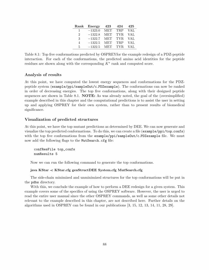
Rank Energy 423 424 4251 −1323.0 MET TRP VAL2 −1322.8 MET TYR VAL3 −1322.7 MET TYR VAL4 −1322.5 MET TRP VAL5 −1322.5 MET TYR VAL
Table 8.1: Top five conformations predicted by OSPREYfor the example redesign of a PDZ-peptideinteraction. For each of the conformations, the predicted amino acid identities for the peptideresidues are shown along with the corresponding K∗ rank and computed score.
Analysis of results
At this point, we have computed the lowest energy sequences and conformations for the PDZ-peptide system (example/ppi/sampleOut/c PDZexample). The conformations can now be rankedin order of decreasing energies. The top five conformations, along with their designed peptidesequences are shown in Table 8.1. NOTE: As was already noted, the goal of the (oversimplified)example described in this chapter and the computational predictions is to assist the user in settingup and applying OSPREY for their own system, rather than to present results of biomedicalsignificance.
Visualization of predicted structures
At this point, we have the top mutant predictions as determined by DEE. We can now generate andvisualize the top predicted conformations. To do this, we can create a file (example/ppi/top confs)with the top five conformations from the example/ppi/sampleOut/c PDZexample file. We mustnow add the following flags to the MutSearch.cfg file:
confResFile top_confs
numResults 5
Now we can run the following command to generate the top conformations.
java KStar -c KStar.cfg genStructDEE System.cfg MutSearch.cfg
The side-chain minimized and unminimized structures for the top conformations will be put inthe pdbs directory.
With this, we conclude the example of how to perform a DEE redesign for a given system. Thisexample covers some of the specifics of using the OSPREY software. However, the user is urged toread the entire user manual since the other OSPREY commands, as well as some other details notrelevant to the example described in this chapter, are not described here. Further details on thealgorithms used in OSPREY can be found in our publications [3, 15, 12, 13, 14, 11, 28, 29].
88

Appendix A
OSPREY Class Summary
This Appendix is intended to serve as a starting point for users interested in modifying and ex-tending the OSPREY source code. A summary of the OSPREY classes is as follows:
• Amber96ext: This class handles the energy computation for a given molecule. The Amberforce field parameters are read in and saved upon initialization. The EEF1 solvation param-eters are also read in using the EEF1 class functions. The energy (including electrostatic,vdW, and solvation) and gradient computation for the full molecule or a selected subset ofthe molecule atoms is performed by this class.
• Amber96PolyPeptideResidue: This class contains hard-coded templates for the differentamino acid types. These templates are used when performing residue mutations.
• AminoAcidTemplates: This class reads from three data files specifying amino acid residues, N-terminal amino acid residues, and C-terminal amino acid residues. Information read includeselement type, atom type, limited connectivity, and partial charge. By matching these aminoacid templates to actual residues in a molecule, the corresponding template atom types andpartial charges can be assigned to the matched residues.
• Atom: Handles functions and data associated with atoms. Example functions include addinga bond between atoms, computing torsion, computing atom distance, etc. Some of the datamembers include the atom name, radius, mass, coordinates, and bond information.
• Backbone: Handles the backbone representation for the protein; Applies (phi,psi) changes tothe molecule; Assumes that the order of the atoms for the phi angle is C(i-1), N(i), CA(i),C(i), and for the psi angle: N(i), CA(i), C(i), N(i+1).
• Backrub: Implements a backrub perturbation for DEEPer calculations.
• BackrubMinimizer: Handles two types of energy minimization: (1) the minimization requiredfor computing the pairwise energy matrices; (2) the minimization of a full conformation: theside-chain dihedrals are kept rigid, while the backbone is allowed to move using backrubmotions. Currently, Backrub minimization can be applied only to the system strand of themolecule; the ligand (if present) is allowed to rotate and translate.
• Backrubs: Handles the application of the Richardsons’ Backrub motions for a given residuein a protein.
89
• BBMinimizer: Handles two types of backbone energy minimization for BD: (1) the min-imization required for computing the pairwise energy matrices; (2) the minimization of afull conformation: the side-chain dihedrals are kept rigid, while the backbone dihedrals areallowed to move within given limits.
• BoundFlags: Applies the Bounding Flags pruning criteria: computes a lower bound on theenergy of all conformations that contain a given rotamer pair (ir,js), for each rotamer pair.
• CommucObj: The CommucObj class is a data structure used in communication between themaster and slave nodes. It is basically just a data container. It allows the master node tospecify what type of search the slave should perform and it allows the slave to return theresult of the computation to the master.
• ConfPair: This class is used to store conformations (defined by their rotamer numbers) andthe energy of each conformation. Objects of this class can be sorted by energy so that onlythe top conformations are stored and later saved to a PDB in KSParser.
• DEE: Base class containing common data and functionality for other DEE classes.
• DEEGoldstein: Performs simple Goldstein DEE rotamer pruning.
• DEEGoldsteinPairs: Performs DEE Goldstein pairs rotamer pruning.
• DEEGoldsteinTriples: Performs DEE Goldstein triples pruning.
• DEEIndirect: Performed indirect pruning.
• DEESplit1f: Performs full split-DEE (conformational splitting) with 1 plit position.
• DEESplit2f: Performs full split-DEE (conformational splitting) with 2 plit positions.
• EEF1: Manages the EEF1 solvation parameters; EEF1 handles only natural amino acids,so solvation energies are computed for proteins and ligands (natural amino acids) only, andnot cofactors; Some important notes about assumptions of the EEF1 model are given in thecomments to getSolvationParameters().
• EnvironmentVars: This is a “global variable” static class. OSPREY stores here configurationvariables that are global and do not change.
• ExpansionQueue: This queue is ordered in terms of increasing f(n) values of the nodes in theA* expansion tree; only the visible nodes are contained in the queue.
• ExpFunction: Manages the computation of exp(x) for large values of x, using BigDecimal; Forlarge values of x, the standard Math.exp(x) cannot be used, since it only has double precision;Implements pow() for integer powers of a BigDecimal number and an approximation to thenatural logarithm of a BigDecimal number.
• ForceField: Interface for different types of force fields (currently not used).
• FullStructureSwitch: Implements a full structure switch perturbation.
90

• GenericResidueTemplates: This class reads from a generic residue file that includes elementtype, AMBER atom type, limited connectivity, and partial charge. This file is analogousto AminoAcidTemplates.java; instead of amino acid parameters, parameters for general com-pounds and nucleic acids (referred to as ‘generic residues’) are read. By matching these genericresidue templates to actual generic residues in a molecule, the corresponding template atomtypes and partial charges can be assigned to the matched residues. The format of the inputparameter file is similar to the PARM AMBER datafiles, identical to the all amino94.in.
• KSParser: The main class that sets up and handles the basic OSPREY computation andrelated functions. The OSPREY functions include: doDEE - perform DEE/A* redesign (thisincludes MinDEE, BD, and BRDEE); genStructDEE - generate structures for a selected setof the top doDEE conformations; precomputeBackrubs - precompute a list of allowed back-rubs for each flexible residue position (used by BRDEE); KSMaster - perform K* redesign;doSinglePartFn - generate (bound or unbound) structures for the K* ensemble of a givenprotein-ligand complex; doResEntropy - use SCMF to compute the residue entropy for each(non-Pro) residue in a protein.
• KStar: This is the main class for the KStar program; essentially just a wrapper for theKSParser class.
• KSthread: Thread that is run when KStar uses threaded computation instead of mpi.
• LoopClosureAdjustment: Implements a loop closure adjustment or a secondary structureadjustment perturbation.
• MinDEEIntervals: Computes the single and pair interval terms in the MinDEE/BD/BRDEEcriteria. This class is not used for traditional DEE.
• Molecule: Handles functions and data associated with molecules. Handles rotations/translationsof (parts of) molecules. Manages the data associated with a molecule; handles changes tothe molecule (e.g., coordinate changes, deletion or addition of residues, etc.). Determines thebond information for the molecule.
• MPIToThread: This class is a wrapper for all of the mpi calls so that if a threaded computationis used the threads are queried like they are compute nodes.
• MSAStar: Uses A* search for single or multiple mutation sequences simultaneously to re-turn the minimum-energy conformation; each consecutive run returns the next lowest-energyconformation, in order.
• MSMinBounds: Performs two different operations, depending on the input parameters: 1)Applies the Bounds/MinBounds pruning criteria: computes a lower bound on the energyof all conformations that contain a given rotamer ir, for each rotamer; 2) Computes: (a) alower bound on the energy of all conformations that contain a pruned rotamer, and (b) allconformations that are pruned due to unallowed sterics.
• MutationManager: The MutationManager class maintains a list of mutations to be tested,maintains their scores, prints a log file, and generally manages the mutations to test.
91

• OneMutation: Handles the data for a single mutation sequence. Contains the amino acididentities for the given sequence and can contain the computed score. Implements a methodfor comparing two sequences that is used for sorting all sequences with respect to differentcriteria.
• PairwiseEnergyMatrix: Stores interaction energies for pair of rotamers, as well as the intra-energies of the rotamers and interaction energies of the template with the rotamers and withitself.
• ParamSet: Handles reading in and managing parameter/value pairs from the input configu-ration files.
• PartialStructureSwitch: Implements a partial structure switch perturbation.
• PDBChemModel: Reads a structure from a PDB file. Also performs autofixing.
• PertFileHandler: Reads and writes perturbation files.
• Perturbation: Handles functions and data associated with a perturbation, for DEEPer calcu-lations.
• PerturbationSelector: Implements the automatic perturbation selector module for DEEPer.
• PMinimizer: This is a subclass of SimpleMinimizer that minimizes with respect to perturba-tion parameters as well as sidechain dihedrals. Used instead of SimpleMinimizer for DEEPercalculations.
• ProbeStericCheck: Implements a steric check for atom pairs based on the Richardsons’ Probeapproach.
• ProlineFlip: Implements a proline flip perturbation.
• PrunedRotamers: Stores the information about whether a rotamer is pruned or not.
• QueueNode: Handles the data for a single node in the A* queue.
• RamachandranChecker: Provides functionality for checking if a backbone conformation isRamachandran-allowed; used in automatic perturbation selection for DEEPer.
• ReducedEnergyMatrix: Compact representation of the pairwise energy matrix, holding onlyinformation for unpruned rotamers. Used in A*.
• Residue: Handles functions and data associated with residues.
• ResSymmetry: Provides functionality related to symmetries of amino acids; used to identifythe current rotamers in a structure.
• RotamerLibrary: This class implements a rotamer library reader. It reads from an input filethat contains rotamer information for amino acid types or other generic residues.
92

• RotamerSearch: This class provides a variety of tools and search algorithms for doing rotamer-based searching over molecular conformations. Contains functions for computing the pairwiseenergy matrices and for performing DEE/A* and K* (with different types of minimization)mutation searches. The functions in this class are typically called after the necessary setupin KSParser.java is performed.
• RotMatrix: This class implements rotation matricies.
• RyanComparable: Interface for comparing objects.
• RyanQuickSort: This class implements quick sort; sorted objects must implement RyanCom-parable.
• SamplingEEntries: Handles data storage for elements in the pairwise energy matrices.
• SaveMolecule: Writes a structure to a PDB file.
• Shear: Implements a shear perturbation.
• SimpleMinimizer: This class implements a simple energy minimization routine for the side-chains only. Handles the computation of the Amber dihedral energy penalties (for minimizingaway from the initial rotamer dihedrals). Additionally there is a special residue, the ligand,that can translate and globally rotate.
• StericCheck: Implements functions for checking the steric overlap for specified parts of a givenstructure at different stages of the A* expansion of the conformation tree.
• Strand: Handles functions and data associated with strands.
• StrandRCs: Subclass of StrandRotamers handling residue conformations instead of rotamers(basically StrandRotamers for DEEPer).
• StrandRotamers: This class handles rotamer assignment and maintenance for a given strand.Performs rotamer swaps and amino acid mutations for this strand.
• SturmSolver: Solves high-degree polynomial equations. Used for loop closure adjustment andsecondary structure adjustment perturbations. This class and the class TripeptideClosure arebased on C code released with [5].
• ThreadElement: Handles all of the messages (ThreadMessages) that have been sent to theslave thread.
• ThreadMessage: Mimics an mpi message. When running in threaded mode each thread actslike a compute node so these objects are passed instead of mpi messages.
• TripeptideClosure: Identifies alternate conformations of a tripeptide with specified bond an-gles and lengths and ω dihedrals. Used for loop closure adjustment and secondary structureadjustment perturbations. This class and the class SturmSolver are based on C code releasedwith [5].
• VolModule: This class computes a crude molecular volume for a specified molecule.
93
Bibliography
[1] R. Abagyan and M. Totrov. Biased probability monte carlo conformational searches andelectrostatic calculations for peptides and proteins. Journal of Molecular Biology, 235(3):983– 1002, 1994.
[2] B. R. Brooks, C. L. Brooks III, A. D. Mackerell Jr., L. Nilsson, R. J. Petrella, B. Roux, Y. Won,G. Archontis, C. Bartels, S. Boresch, A. Caflisch, L. Caves, Q. Cui, A. R. Dinner, M. Feig,S. Fischer, J. Gao, M. Hodoscek, W. Im, K. Kuczera, T. Lazaridis, J. Ma, V. Ovchinnikov,E. Paci, R. W. Pastor, C. B. Post, J. Z. Pu, M. Schaefer, B. Tidor, R. M. Venable, H. L.Woodcock, X. Wu, W. Yang, D. M. York, and M. Karplus. CHARMM: the biomolecularsimulation program. Journal of Computational Chemistry, 30(10):1545–1614, July 2009.
[3] C. Chen, I. Georgiev, A. C. Anderson, and B. R. Donald. Computational structure-basedredesign of enzyme activity. PNAS USA, 106(10):3764–3769, 2009.
[4] W. Cornell, P. Cieplak, C. Bayly, I. Gould, K. Merz, D. Ferguson, D. Spellmeyer, T. Fox,J. Caldwell, and P. Kollman. A second generation force field for the simulation of proteins,nucleic acids and organic molecules. JACS, 117:5179–97, 1995.
[5] E. A. Coutsias, C. Seok, M. P. Jacobson, and K. A. Dill. A kinematic view of loop closure.Journal of Computational Chemistry, 25(4):510–528, 2004.
[6] I. Davis, A. Leaver-Fay, V. Chen, J. Block, G. Kapral, X. Wang, L. Murray, W. Arendall,J. Snoeyink, J. Richardson, and D. Richardson. MolProbity: all-atom contacts and structurevalidation for proteins and nucleic acids. Nucleic Acids Res., 35:W375–383, Jul 2007.
[7] W. L. DeLano. The pymol molecular graphics system (2008). DeLano Scientific, Palo Alto,California, USA. http://www.pymol.org.
[8] J. Desmet, M. De Maeyer, B. Hazes, and I. Lasters. The dead-end elimination theorem andits use in protein side-chain positioning. Nature, 356:539–542, 1992.
[9] B. R. Donald. Algorithms in Structural Molecular Biology. The MIT Press (Cambridge, MA),2011.
[10] K. M. Frey, I. Georgiev, B. R. Donald, and A. C. Anderson. Predicting resistance mutationsusing protein design algorithms. Proc Natl Acad Sci U S A, 107(31):13707–13712, 2010.
[11] P. Gainza, K. E. Roberts, and B. R. Donald. Protein design using continuous rotamers. PLoSComput Biol, 8(1):e1002335, 01 2012.
94

[12] I. Georgiev and B. R. Donald. Dead-end elimination with backbone flexibility. Bioinformatics,23(13):i185–94, 2007. Proc. International Conference on Intelligent Systems for MolecularBiology (ISMB), Vienna, Austria (2007).
[13] I. Georgiev, D. Keedy, J. S. Richardson, D. C. Richardson, and B. R. Donald. Algorithm forbackrub motions in protein design. Bioinformatics, 24(13):i196–204, 2008. Proc. InternationalConference on Intelligent Systems for Molecular Biology (ISMB), Toronto, Canada (2008).
[14] I. Georgiev, R. Lilien, and B. R. Donald. Improved pruning algorithms and divide-and-conquer strategies for dead-end elimination, with application to protein design. Bioinformatics,22(14):e174–183, 2006. Proc. International Conference on Intelligent Systems for MolecularBiology (ISMB), Fortaleza, Brazil (2006).
[15] I. Georgiev, R. Lilien, and B. R. Donald. The minimized dead-end elimination criterion andits application to protein redesign in a hybrid scoring and search algorithm for computingpartition functions over molecular ensembles. J Comput Chem, 29(10):1527–42, 2008.
[16] D. Gordon and S. Mayo. Radical performance enhancements for combinatorial optimizationalgorithms based on the dead-end elimination theorem. J. Comput. Chem., 19:1505–1514,1998.
[17] M. A. Hallen and B. R. Donald. comets (Constrained Optimization of Multistate Energiesby Tree Search): A provable and efficient algorithm to optimize binding affinity and speci-ficity with respect to sequence. Research in Computational Molecular Biology (RECOMB)proceedings, In press, 2015.
[18] M. A. Hallen, D. A. Keedy, and B. R. Donald. Dead-end elimination with perturbations(DEEPer): A provable protein design algorithm with continuous sidechain and backbone flex-ibility. Proteins, 81(1):18–39, 2013.
[19] W. Humphrey, A. Dalke, and K. Schulten. VMD – Visual Molecular Dynamics. Journal ofMolecular Graphics, 14:33–38, 1996.
[20] R. Lab. The software page :: Kinemage website. http://kinemage.biochem.duke.edu/
software/index.php. [Online; accessed 12 Mar 2009].
[21] T. Lazaridis and M. Karplus. Effective energy function for proteins in solution. PROTEINS:Structure, Function, and Genetics, 35:133–152, 1999.
[22] A. Leach and A. Lemon. Exploring the conformational space of protein side chains usingdead-end elimination and the A* algorithm. Proteins, 33:227–239, 1998.
[23] R. Lilien, B. Stevens, A. Anderson, and B. R. Donald. A novel ensemble-based scoring andsearch algorithm for protein redesign, and its application to modify the substrate specificity ofthe Gramicidin Synthetase A phenylalanine adenylation enzyme. J Comp Biol, 12(6–7):740–761, 2005.
[24] S. M. Lippow, K. D. Wittrup, and B. Tidor. Computational design of antibody-affinity im-provement beyond in vivo maturation. Nat Biotechnol, 25(10):1171–6, 2007.
95

[25] S. C. Lovell, J. Word, J. Richardson, and D. Richardson. The penultimate rotamer library.Proteins, 40:389–408, 2000.
[26] D. A. Pearlman, D. A. Case, J. W. Caldwell, W. S. Ross, T. E. Cheatham, S. DeBolt, D. Fer-guson, G. Seibel, and P. Kollman. AMBER, a package of computer programs for applyingmolecular mechanics, normal mode analysis, molecular dynamics and free energy calculationsto simulate the structural and energetic properties of molecules. Comput Phys Commun,91(1-3):1–41, Sept. 1995.
[27] N. Pierce, J. Spriet, J. Desmet, and S. Mayo. Conformational splitting: a more powerfulcriterion for dead-end elimination. J. Comput. Chem., 21:999–1009, 2000.
[28] K. E. Roberts, P. R. Cushing, P. Boisguerin, D. R. Madden, and B. R. Donald. Design ofprotein-protein interactions with a novel ensemble-based scoring algorithm. In Research inComputational Molecular Biology, volume 6577 of Lecture Notes in Computer Science, pages361–376. Springer Berlin / Heidelberg, 2011.
[29] K. E. Roberts, P. R. Cushing, P. Boisguerin, D. R. Madden, and B. R. Donald. Design of apdz domain peptide inhibitor that rescues cftr activity. PLoS Comput Biol. To Appear, 2012.
[30] C. A. Voigt, S. L. Mayo, F. H. Arnold, and Z. G. Wang. Computational method to reduce thesearch space for directed protein evolution. Proc Natl Acad Sci U S A, 98(7):3778–83, 2001.
[31] J. Wang, W. Wang, P. Kollman, and D. Case. Antechamber, an accessory software packagefor molecular mechanics calculations. J. Mol. Graphics Model., 25:247–260, 2006.
[32] S. Weiner, P. Kollman, D. Case, U. Singh, C. Ghio, G. Alagona, S. Profeta, and P. Weiner.A new force field for molecular mechanical simulation of nucleic acids and proteins.J. Am. Chem. Soc., 106:765–784, 1984.
[33] J. M. Word, S. C. Lovell, T. H. LaBean, H. C. Taylor, M. E. Zalis, B. K. Presley, J. S.Richardson, and D. C. Richardson. Visualizing and quantifying molecular goodness-of-fit:small-probe contact dots with explicit hydrogen atoms. J Mol Biol, 285(4):1711–1733, 1999.
[34] J. M. Word, S. C. Lovell, J. S. Richardson, and D. C. Richardson. Asparagine and glutamine:using hydrogen atom contacts in the choice of side-chain amide orientation. J Mol Biol,285(4):1735–1747, 1999.
[35] C. Yanover, M. Fromer, and J. M. Shifman. Dead-end elimination for multistate protein design.Journal of Computational Chemistry, 28(13):2122–2129, 2007.
96


![Osprey - Aerospace - Tiger Squadrons [Osprey - Aerospace].pdf](https://img.pdfslide.net/doc/110x75/55cf9675550346d0338b9dbe/osprey-aerospace-tiger-squadrons-osprey-aerospacepdf.jpg)


![Osprey - Colour Series - Sky Truck 2 [Osprey Color]](https://img.pdfslide.net/doc/110x75/545d6543b0af9fb32c8b5093/osprey-colour-series-sky-truck-2-osprey-color.jpg)