Embed Size (px)
Citation preview
●�Read�this�“Operation�Manual”�prior�to�usage�to�ensure�safe�and�correct�operation.
●�Keep�this�in�a�safe�place�for�future�reference.
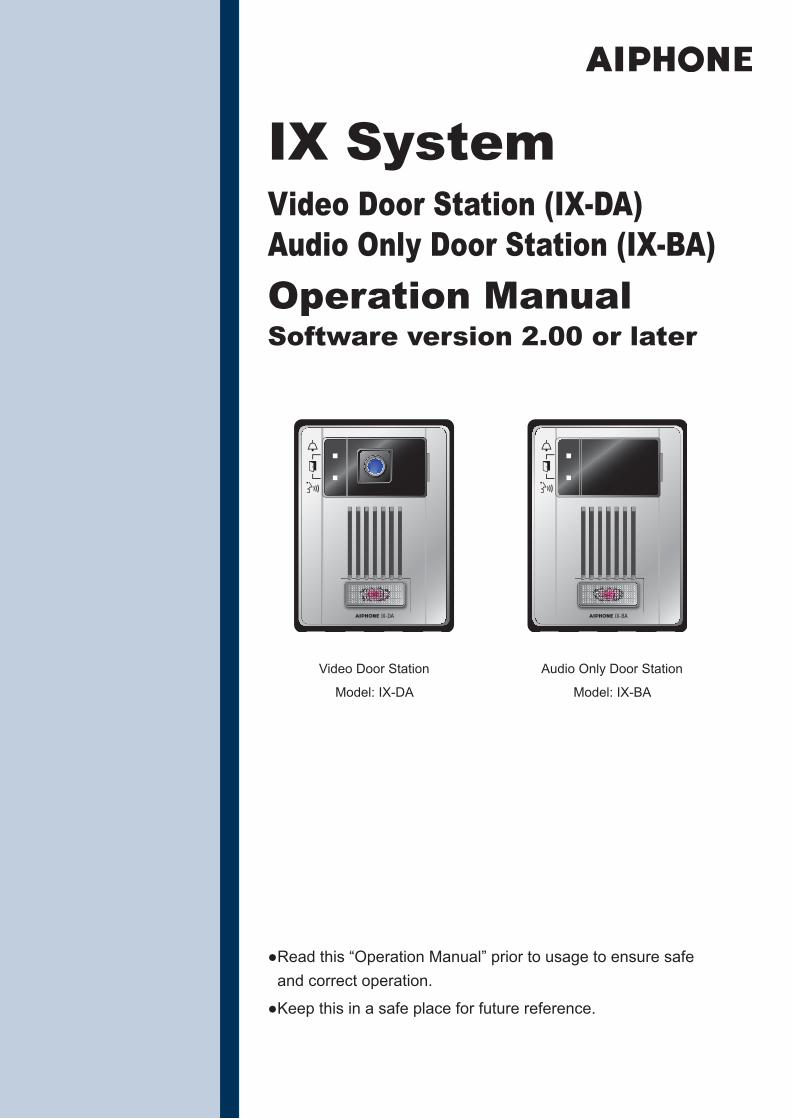
Video�Door�Station
Model:�IX-DA
Audio�Only�Door�Station
Model:�IX-BA
IX SystemVideo Door Station (IX-DA)Audio Only Door Station (IX-BA)Operation ManualSoftware version 2.00 or later
2
PrecautionsThis�symbol�is�intended�to�alert�the�user�to�cautions�(including�warnings�and�cautions).
This�symbol�is�intended�to�alert�the�user�to�prohibited�actions.
This�symbol�is�intended�to�alert�the�user�to�actions�that�are�forced�or�instructed.
Negligence�could�result�in�injury�to�people�or�damage�to�property.Caution1. Do not put anything on the unit or
cover the unit with cloth, etc.Fire�or�unit�trouble�could�result.
2. Do not use the handset when you perform a call test or check the chime volume.It�may�cause�damage�to�your�ear.�Be�sure�to�use�the�built-in�speaker.
3. Do not install the unit in the following locations.Fire,�electric�shock,�or�unit�trouble�could�result.• Places under direct sunlight or
places near heating equipment that varies in temperature.
• Places subject to dust, oil, chemicals, hydrogen sulfide (hot spring).
• Places subject to moisture and humidity extremes, such as bathrooms, cellars, greenhouses, etc.
• Places where the temperature is quite low, such as inside a refrigerated area or in front of an air conditioner.
• Places subject to steam or smoke (near heating or cooking surfaces).
• Where noise generating devices such as dimmer switches or inverter electrical appliances are close by.
• Locations subject to frequent vibration or impact.
• Locations subject to extremely powerful electric fields.
Negligence�could�result�in�death�or�serious�injury.Warning
Dismantling�or
alteration
1. Do not dismantle or alter the unit.Fire�or�electric�shock�could�result.
2. Keep the unit away from water or any other liquid.Fire�or�electric�shock�could�result.
3. High voltage is present internally. Do not open the case.Electric�shock�could�result.
4. Do not put any metal or flammable material into the unit through the openings. Fire,�electric�shock,�or�unit�trouble�could�result.
5. Do not install or use near gases or flammable materials. The�unit�is�not�explosion-proof.�Fire�or�explosion�could�result.
1 Precautions
3
�Precautions1Operation precautions
General considerations
1.� Keep�the�unit�more�than�1m�(3.3')�away�from�radio�or�TV�set.2.� If�the�unit�is�down�or�does�not�operate�properly,�unplug�the�power�supply�or�turn�off�the�POWER�switches.3.� The�unit�case�may�become�a�warm�with�use,�but�this�is�not�a�unit�malfunction.4.� If�you�enable�“Second�Video�Encoder”�(→�page�18),�the�unit�will�continue�to�output�video.�When�this�happens,�the�
unit�case�may�become�warm�but�this�is�not�a�unit�malfunction.5.� If�it�is�used�close�to�a�cellular�phone,�the�unit�may�malfunction.6.� The�unit�turns�inoperative�during�power�failure.7.� In�areas�where�broadcasting�station�antennas�are�close�by,�the�intercom�system�may�be�affected�by�radio�
frequency�interference.8.� During�communication,�If�you�stand�too�far�away,�it�may�be�difficult�for�the�other�person�to�hear�the�
communication.9.� If�there�are�loud�noises�around�the�unit�(such�as�music�playing�or�children�crying),�the�sound�may�break�up�and�
be�difficult�to�hear.10.�During�communication,�if�you�speak�before�the�other�person�has�finished�talking,�your�voice�may�not�come�
through�clearly.�Communication�will�proceed�smoothly�if�you�wait�until�the�other�person�has�finished�before�speaking.
11.�During�monitoring,�the�noise�cut�function�does�not�work�for�making�outside�sounds�easy�to�hear,�so�the�noise�may�be�heard�louder�than�during�communication.
12.�This�product,�being�a�control�unit�of�door�release,�should�not�be�used�as�a�crime�prevention�device.13.�The�discrimination�between�day�and�night�is�performed�automatically�by�the�door�station.�Though�the�
discrimination�result�may�vary�depending�on�the�installation�environment,�it�is�not�a�malfunction.14.�Due�to�the�environmental�sound�around�the�unit,�it�may�hinder�smooth�communication,�but�this�is�not�a�
malfunction.15.�At�night,�due�to�reduced�lighting�on�the�object,�the�monitor�sees�more�noise�and�the�face�becomes�more�difficult�
to�see,�but�this�is�not�malfunction.16.�At�a�gate�or�porch�illuminated�by�a�fluorescent�lamp,�the�picture�may�vary,�but�this�is�not�a�malfunction.17.�The�outline�of�video�images�displayed�by�video�door�station�may�differ�from�that�of�the�actual�person(s)�or�
background,�but�this�is�not�a�malfunction.18.�If�the�surface�of�a�video�door�station�freezes�during�wintertime,�the�picture�may�become�difficult�to�see�or�the�call�
button�(including�the�call�button�of�audio�door�station)�may�not�move,�but�this�is�not�a�malfunction.19.�Warm-color�lighting�shining�on�the�video�door�station�may�change�the�tint�of�the�picture�on�the�monitor.20.�When�using�fluorescent�lights�to�illuminate�the�screen�its�colors�may�periodically�change�(color�rolling),�but�this�is�
not�a�malfunction.21.�When�outside�temperature�lowers�sharply�after�rainfall,�etc.,�the�inside�of�the�camera�may�fog�up�slightly,�causing�
a�blurry�picture,�but�this�is�not�a�malfunction.�Normal�operation�will�be�restored�when�moisture�evaporates.22.�When�the�unit’s�screen�is�illuminated�with�strong�light,�the�image�looks�white�or�silhouetted.�But�this�is�not�a�unit�
trouble.23.�Aiphone�assumes�no�responsibility�for�corruption�of�saved�information�(such�as�changes�to�or�deletion�of�saved�
information).�Please�be�aware�of�this�in�advance.
4
�Precautions1
Notes on using this system
1.� Depending�on�the�network�environment�and�computer,�it�may�not�be�useable.2.� You�need�to�set�the�ID/password�to�access�the�web�server�when�changing�the�system�settings�or�doing�the�
system�maintenance.�The�system�administrator�must�keep�the�ID/password�without�fail.3.� The�ID/Password�to�access�the�web�server�for�setting�the�system�is�the�customer’s�responsibility.�Make�sure�you�
set�a�password�that�cannot�be�easily�guessed�by�a�third�party.�We�recommend�that�you�change�the�ID/Password�on�a�regular�basis.
4.� You�may�not�be�able�to�operate�stations�while�updating�the�System�settings�by�using�a�PC.5.� Video�images�and/or�sounds�may�be�interrupted�depending�on�the�communication�status.6.� If�there�is�an�error�in�the�setting�of�the�corresponding�station,�calls�will�not�work�properly.7.� If�you�are�experiencing�difficulties�in�the�use�of�the�system,�please�check�our�website�at�http://www.aiphone.net/.
Notice
1.� Aiphone�assume�no�responsibility�for�damages�as�a�result�of�delayed�or�unusable�services,�which�were�due�to�failures�in�network�equipment,�communication�services�by�Internet�and�cellular�phone�companies,�line�interruptions,�communication�failures,�or�inaccuracies�or�omissions�in�the�transmission�unit.
2.� If�personal�information�is�leaked�by�eavesdropping�or�unauthorized�access�in�the�communication�paths�over�the�Internet,�please�be�aware�that�Aiphone�assume�no�responsibility�for�the�damages.
3.� We�will�under�no�conditions�be�liable�for�damage�that�occurs�due�to�the�inability�to�communicate�due�to�malfunctions,�problems,�or�operational�errors�in�this�product.
4.� We�will�under�no�conditions�be�liable�for�any�damages�or�losses�resulting�from�this�product’s�contents�or�specifications.
5.� This�manual�was�created�by�Aiphone�Co.,�Ltd.,�all�rights�reserved.�Copying�a�part�of�or�this�entire�manual�without�prior�permission�from�Aiphone�Co.,�Ltd.�is�strictly�forbidden.
6.� Please�note�that�images�and�illustrations�depicted�in�this�manual�may�differ�from�the�actual�ones.7.� Please�note�that�this�manual�may�be�revised�or�changed�without�prior�notice.8.� Please�note�that�product�specifications�may�be�changed�for�the�sake�of�improvement�without�prior�notice.9.� Please�be�aware�that�it�is�the�customer’s�responsibility�to�ensure�that�their�computer�is�secure.�We�will�under�no�
conditions�be�liable�for�security�failures.10.�This�system�is�not�intended�for�life�support�or�crime�prevention.�It�is�just�a�supplementary�means�of�conveying�
information.�Aiphone�will�under�no�conditions�be�liable�for�loss�of�life�or�property�which�occurs�while�the�system�is�being�operated.
11.�This�system�is�not�intended�for�preventing�physical�injury,�accidents�caused�by�disasters�and�property�damage.12.�Please�receive�and�retain�all�configuration�data�from�the�supplier.�If�you�lose�the�configuration�data,�there�are�
cases�where�maintenance�and�after-sales�service�calls�may�incur�additional�setup�fees.
5
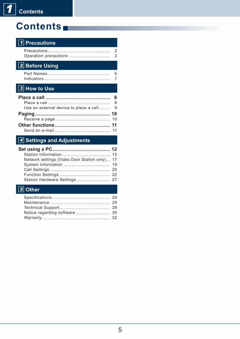
Contents1 PrecautionsPrecautions�............................................... � 2Operation�precautions�............................... � 3
2 Before UsingPart�Names�............................................... � 6Indicators�.................................................. � 7
3 How to UsePlace a call ................................................ 8
Place�a�call�............................................... � 8Use�an�external�device�to�place�a�call�........ � 9
Paging ........................................................ 10Receive�a�page�......................................... � 10
Other functions ......................................... 11Send�an�e-mail�.......................................... � 11
4 Settings and AdjustmentsSet using a PC ........................................... 12
Station�Information�.................................... � 15Network�settings�(Video�Door�Station�only)�... � 17System�Information�................................... � 19Call�Settings�............................................. � 20Function�Settings�...................................... � 22Station�Hardware�Settings�......................... � 27
5 OtherSpecifications............................................ � 29Maintenance�............................................. � 29Technical�Support�...................................... � 29Notice�regarding�software�.......................... � 30Warranty�................................................... � 32
1 Contents
6
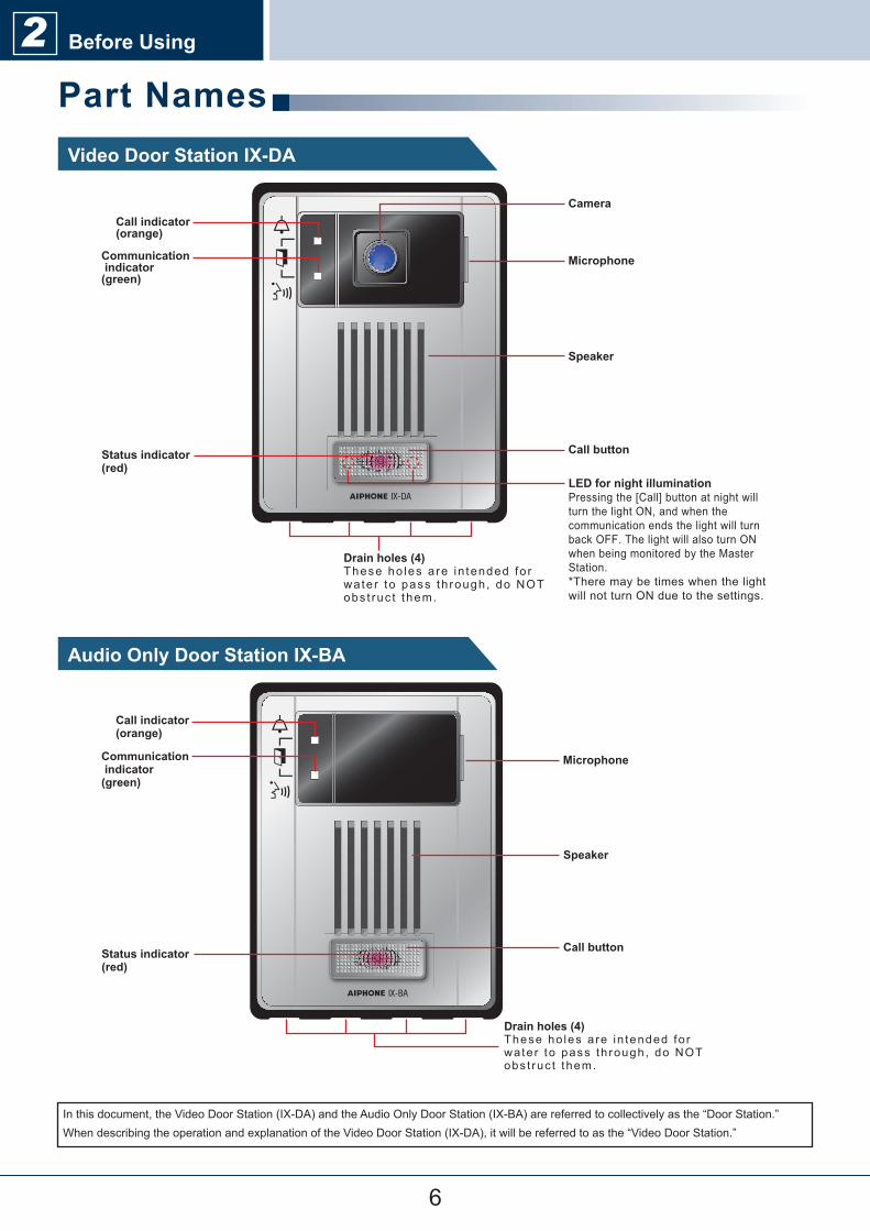
Part NamesVideo Door Station IX-DA
Audio Only Door Station IX-BA
Camera
Microphone
Speaker
Call button
Call indicator (orange)
Communication indicator (green)
Status indicator (red)
LED for night illuminationPressing the [Call] button at night will turn the light ON, and when the communication ends the light will turn back OFF. The light will also turn ON when being monitored by the Master Station.*There may be times when the light will not turn ON due to the settings.
Drain holes (4)These ho les a re in tended fo r wate r to pass th rough, do NOT obs t ruc t them.
Microphone
Speaker
Call button
Call indicator (orange)
Communication indicator (green)
Status indicator (red)
Drain holes (4)These ho les a re in tended fo r wate r to pass th rough, do NOT obs t ruc t them.
In�this�document,�the�Video�Door�Station�(IX-DA)�and�the�Audio�Only�Door�Station�(IX-BA)�are�referred�to�collectively�as�the�“Door�Station.”When�describing�the�operation�and�explanation�of�the�Video�Door�Station�(IX-DA),�it�will�be�referred�to�as�the�“Video�Door�Station.”
2 Before Using
7
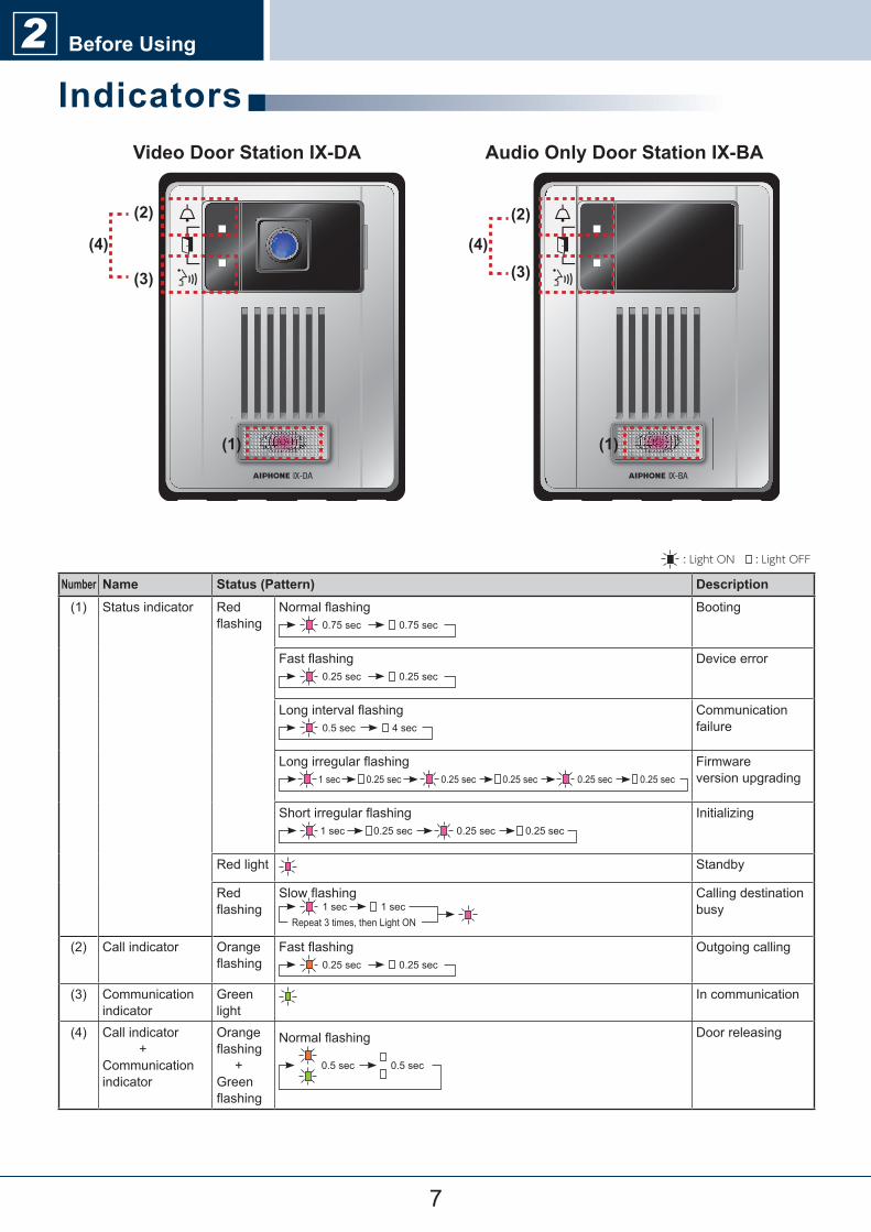
Before Using2Indicators
Number Name Status (Pattern) Description(1) Status�indicator Red�
flashingNormal�flashing
0.75�sec 0.75�secBooting
Fast�flashing0.25�sec 0.25�sec
Device�error
Long�interval�flashing0.5�sec 4�sec
Communication�failure
Long�irregular�flashing1�sec 0.25�sec 0.25�sec 0.25�sec 0.25�sec 0.25�sec
Firmwareversion�upgrading
Short�irregular�flashing1�sec 0.25�sec 0.25�sec 0.25�sec
Initializing
Red�light Standby
Red�flashing
Slow�flashing1�sec 1�sec
Repeat�3�times,�then�Light�ON
Calling�destination�busy
(2) Call�indicator Orange�flashing
Fast�flashing0.25�sec 0.25�sec
Outgoing�calling
(3) Communication�indicator
Green�light
In�communication
(4) Call�indicator����������+Communication�indicator
Orange�flashing�����+Green�flashing
Normal�flashing
0.5�sec 0.5�sec
Door�releasing
: Light ON : Light OFF
Video Door Station IX-DA Audio Only Door Station IX-BA
(1)
(3)
(2)
(4)
(1)
(2)
(3)(4)
8
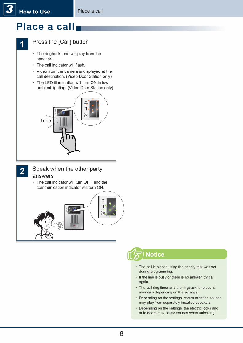
Place a call
1 Press�the�[Call]�button
•� The�ringback�tone�will�play�from�the�speaker.
•� The�call�indicator�will�flash.•� Video�from�the�camera�is�displayed�at�the�call�destination.�(Video�Door�Station�only)
•� The�LED�illumination�will�turn�ON�in�low�ambient�lighting.�(Video�Door�Station�only)
Tone
2 Speak�when�the�other�party�answers•� The�call�indicator�will�turn�OFF,�and�the�communication�indicator�will�turn�ON.
•� The�call�is�placed�using�the�priority�that�was�set�during�programming.
•� If�the�line�is�busy�or�there�is�no�answer,�try�call�again.
•� The�call�ring�timer�and�the�ringback�tone�count�may�vary�depending�on�the�settings.
•� Depending�on�the�settings,�communication�sounds�may�play�from�separately�installed�speakers.
•� Depending�on�the�settings,�the�electric�locks�and�auto�doors�may�cause�sounds�when�unlocking.
Notice
3 How to Use Place�a�call
9
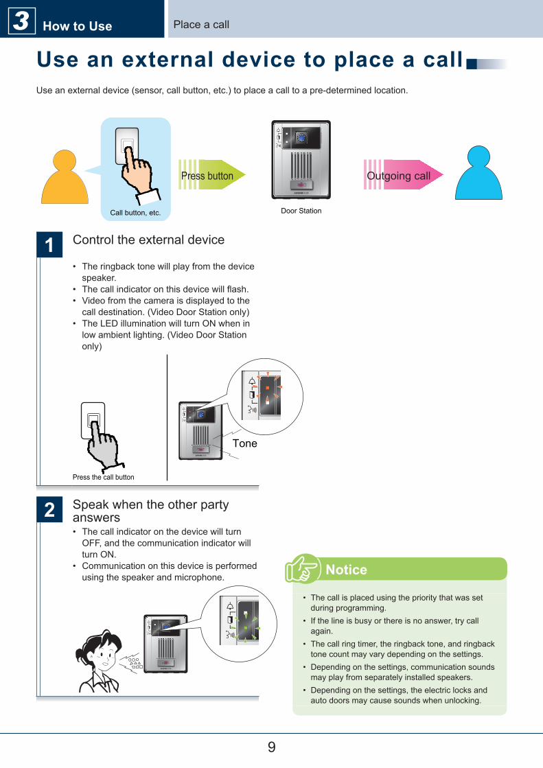
Place�a�callHow to Use3Use an external device to place a callUse�an�external�device�(sensor,�call�button,�etc.)�to�place�a�call�to�a�pre-determined�location.
Door Station
Press button Outgoing call
Call button, etc.
1 Control�the�external�device
•� The�ringback�tone�will�play�from�the�device�speaker.
•� The�call�indicator�on�this�device�will�flash.•� Video�from�the�camera�is�displayed�to�the�call�destination.�(Video�Door�Station�only)
•� The�LED�illumination�will�turn�ON�when�in�low�ambient�lighting.�(Video�Door�Station�only)
Tone
Press the call button
2 Speak�when�the�other�party�answers•� The�call�indicator�on�the�device�will�turn�OFF,�and�the�communication�indicator�will�turn�ON.
•� Communication�on�this�device�is�performed�using�the�speaker�and�microphone.
•� The�call�is�placed�using�the�priority�that�was�set�during�programming.
•� If�the�line�is�busy�or�there�is�no�answer,�try�call�again.
•� The�call�ring�timer,�the�ringback�tone,�and�ringback�tone�count�may�vary�depending�on�the�settings.
•� Depending�on�the�settings,�communication�sounds�may�play�from�separately�installed�speakers.
•� Depending�on�the�settings,�the�electric�locks�and�auto�doors�may�cause�sounds�when�unlocking.
Notice
10
How to Use3
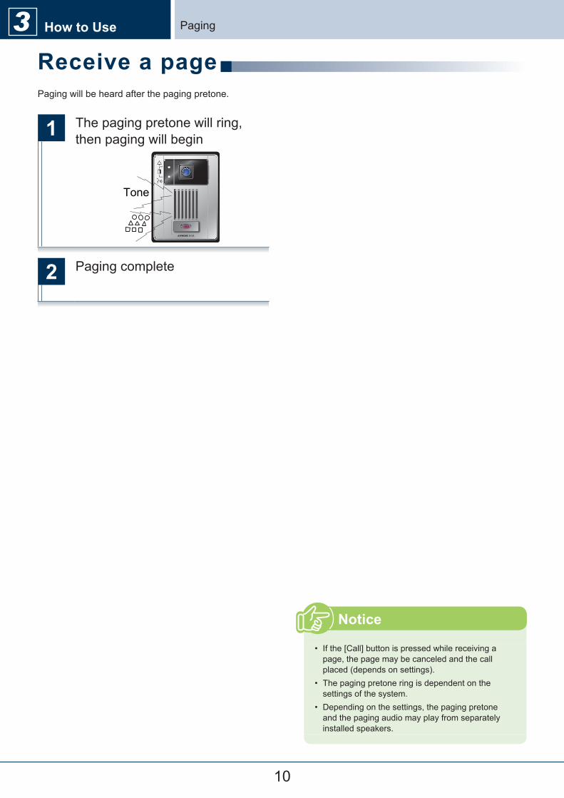
1 The�paging�pretone�will�ring,�then�paging�will�begin
Tone
2 Paging�complete
Receive a pagePaging�will�be�heard�after�the�paging�pretone.
•� If�the�[Call]�button�is�pressed�while�receiving�a�page,�the�page�may�be�canceled�and�the�call�placed�(depends�on�settings).
•� The�paging�pretone�ring�is�dependent�on�the�settings�of�the�system.
•� Depending�on�the�settings,�the�paging�pretone�and�the�paging�audio�may�play�from�separately�installed�speakers.
Notice
Paging
11
How to Use3
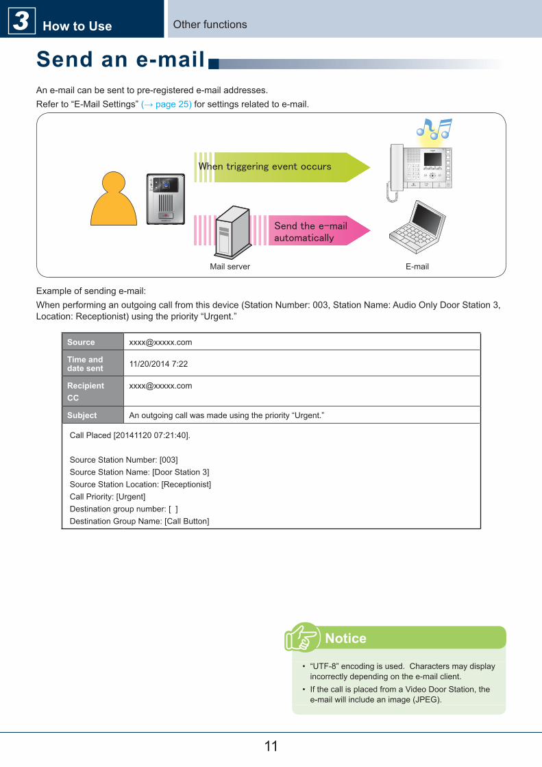
An�e-mail�can�be�sent�to�pre-registered�e-mail�addresses.Refer�to�“E-Mail�Settings”�(→�page�25)�for�settings�related�to�e-mail.
E-mailMail server
Example�of�sending�e-mail:When�performing�an�outgoing�call�from�this�device�(Station�Number:�003,�Station�Name:�Audio�Only�Door�Station�3,�Location:�Receptionist)�using�the�priority�“Urgent.”
Source [email protected]
Time and date sent 11/20/2014�7:22
RecipientCC
Subject An�outgoing�call�was�made�using�the�priority�“Urgent.”
Call�Placed�[20141120�07:21:40].
Source�Station�Number:�[003]Source�Station�Name:�[Door�Station�3]Source�Station�Location:�[Receptionist]Call�Priority:�[Urgent]Destination�group�number:�[��]Destination�Group�Name:�[Call�Button]
Send an e-mail
•� “UTF-8”�encoding�is�used.��Characters�may�display�incorrectly�depending�on�the�e-mail�client.
•� If�the�call�is�placed�from�a�Video�Door�Station,�the�e-mail�will�include�an�image�(JPEG).
Notice
Other�functions
12
Login to this device
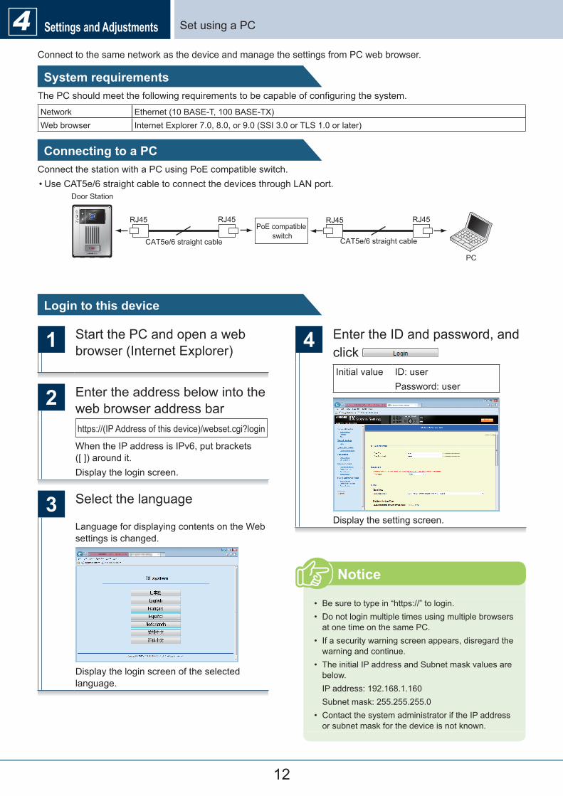
Connect to the same network as the device and manage the settings from PC web browser.
System requirementsThe PC should meet the following requirements to be capable of configuring the system.
Network Ethernet (10 BASE-T, 100 BASE-TX)Web browser Internet Explorer 7.0, 8.0, or 9.0 (SSI 3.0 or TLS 1.0 or later)
Connecting to a PCConnect the station with a PC using PoE compatible switch.•Use CAT5e/6 straight cable to connect the devices through LAN port.
RJ45 RJ45 RJ45 RJ45
PC
CAT5e/6 straight cable CAT5e/6 straight cable
Door Station
PoE compatible switch
1 Start the PC and open a web browser (Internet Explorer)
2 Enter the address below into the web browser address barhttps://(IP Address of this device)/webset.cgi?login
When the IP address is IPv6, put brackets ([ ]) around it.Display the login screen.
3 Select the language
Language for displaying contents on the Web settings is changed.
Display the login screen of the selected language.
4 Enter the ID and password, and click Initial value ID: user
Password: user
Display the setting screen.
• Be sure to type in “https://” to login.• Do not login multiple times using multiple browsers
at one time on the same PC.• If a security warning screen appears, disregard the
warning and continue.• The initial IP address and Subnet mask values are
below.IP address: 192.168.1.160Subnet mask: 255.255.255.0
• Contact the system administrator if the IP address or subnet mask for the device is not known.
Notice
Set using a PC4 Settings and Adjustments
13
Settings and Adjustments4
How to configure
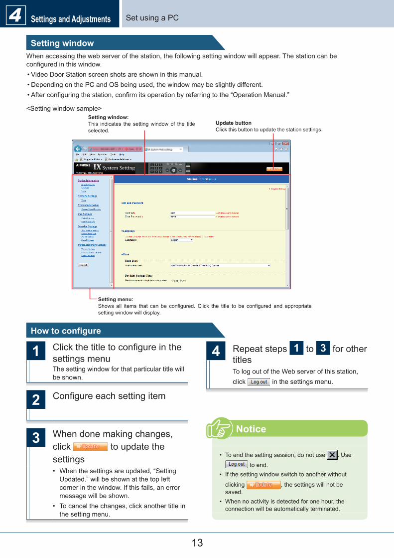
Setting windowWhen�accessing�the�web�server�of�the�station,�the�following�setting�window�will�appear.�The�station�can�be�configured�in�this�window.•�Video�Door�Station�screen�shots�are�shown�in�this�manual.•�Depending�on�the�PC�and�OS�being�used,�the�window�may�be�slightly�different.•�After�configuring�the�station,�confirm�its�operation�by�referring�to�the�“Operation�Manual.”
<Setting�window�sample>
Update buttonClick�this�button�to�update�the�station�settings.
Setting window:This� indicates� the� setting�window�of� the� title�selected.
Setting menu:Shows� all� items� that� can� be� configured.�Click� the� title� to� be� configured� and� appropriate�setting�window�will�display.
1 Click�the�title�to�configure�in�the�settings�menuThe�setting�window�for�that�particular�title�will�be�shown.
2 Configure�each�setting�item
3 When�done�making�changes,�click� �to�update�the�settings•� When�the�settings�are�updated,�“Setting�Updated.”�will�be�shown�at�the�top�left�corner�in�the�window.�If�this�fails,�an�error�message�will�be�shown.
•� To�cancel�the�changes,�click�another�title�in�the�setting�menu.
4 Repeat�steps� 1 �to� 3 �for�other�titlesTo�log�out�of�the�Web�server�of�this�station,�click� �in�the�settings�menu.
•� To�end�the�setting�session,�do�not�use� .�Use�
�to�end.•� If�the�setting�window�switch�to�another�without�
clicking� ,�the�settings�will�not�be�saved.
•� When�no�activity�is�detected�for�one�hour,�the�connection�will�be�automatically�terminated.
Notice
Set�using�a�PC
14
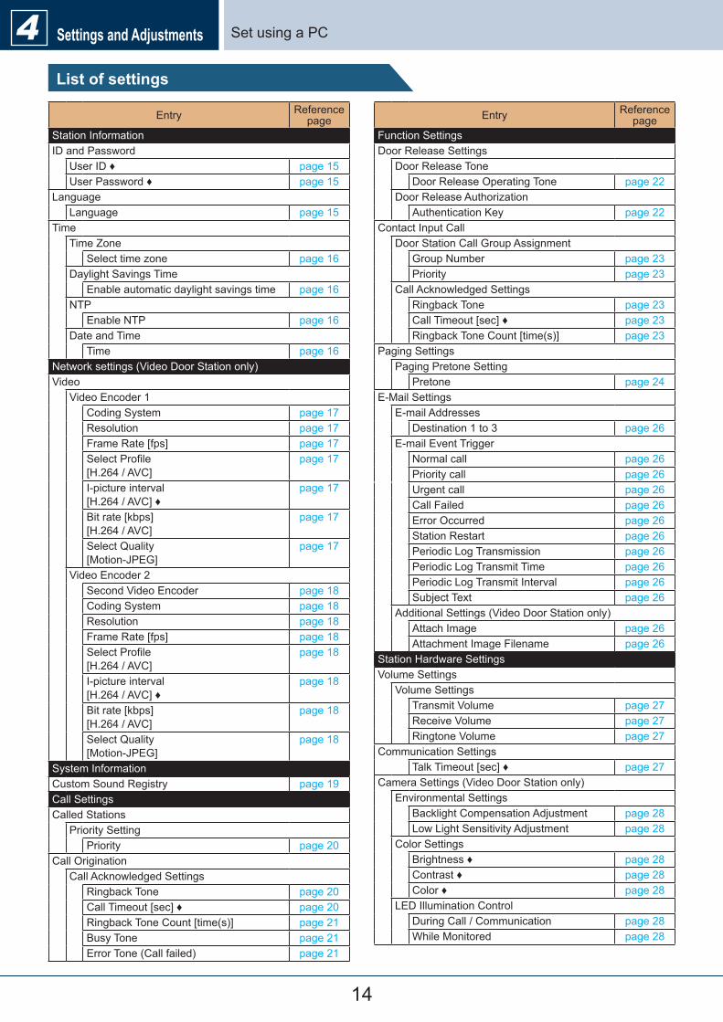
Set�using�a�PCSettings and Adjustments4List of settings
Entry Reference�page
Station�InformationID�and�Password
User�ID�♦ page�15User�Password�♦ page�15
LanguageLanguage page�15
TimeTime�Zone
Select�time�zone page�16Daylight�Savings�Time
Enable�automatic�daylight�savings�time page�16NTP
Enable�NTP page�16Date�and�Time
Time page�16Network�settings�(Video�Door�Station�only)Video
Video�Encoder�1Coding�System page�17Resolution page�17Frame�Rate�[fps] page�17Select�Profile��[H.264�/�AVC]
page�17
I-picture�interval��[H.264�/�AVC]�♦
page�17
Bit�rate�[kbps]��[H.264�/�AVC]
page�17
Select�Quality��[Motion-JPEG]
page�17
Video�Encoder�2Second�Video�Encoder page�18Coding�System page�18Resolution page�18Frame�Rate�[fps] page�18Select�Profile��[H.264�/�AVC]
page�18
I-picture�interval��[H.264�/�AVC]�♦
page�18
Bit�rate�[kbps]��[H.264�/�AVC]
page�18
Select�Quality��[Motion-JPEG]
page�18
System�InformationCustom�Sound�Registry page�19Call�SettingsCalled�Stations
Priority�SettingPriority page�20
Call�OriginationCall�Acknowledged�Settings
Ringback�Tone page�20Call�Timeout�[sec]�♦ page�20Ringback�Tone�Count�[time(s)] page�21Busy�Tone page�21Error�Tone�(Call�failed) page�21
Entry Reference�page
Function�SettingsDoor�Release�Settings
Door�Release�ToneDoor�Release�Operating�Tone page�22
Door�Release�AuthorizationAuthentication�Key page�22
Contact�Input�CallDoor�Station�Call�Group�Assignment
Group�Number page�23Priority page�23
Call�Acknowledged�SettingsRingback�Tone page�23Call�Timeout�[sec]�♦ page�23Ringback�Tone�Count�[time(s)] page�23
Paging�SettingsPaging�Pretone�Setting
Pretone page�24E-Mail�Settings
E-mail�AddressesDestination�1�to�3 page�26
E-mail�Event�TriggerNormal�call page�26Priority�call page�26Urgent�call page�26Call�Failed page�26Error�Occurred page�26Station�Restart page�26Periodic�Log�Transmission page�26Periodic�Log�Transmit�Time page�26Periodic�Log�Transmit�Interval page�26Subject�Text page�26
Additional�Settings�(Video�Door�Station�only)Attach�Image page�26Attachment�Image�Filename page�26
Station�Hardware�SettingsVolume�Settings
Volume�SettingsTransmit�Volume page�27Receive�Volume page�27Ringtone�Volume page�27
Communication�SettingsTalk�Timeout�[sec]�♦ page�27
Camera�Settings�(Video�Door�Station�only)Environmental�Settings
Backlight�Compensation�Adjustment page�28Low�Light�Sensitivity�Adjustment page�28
Color�SettingsBrightness�♦ page�28Contrast�♦ page�28Color�♦ page�28
LED�Illumination�ControlDuring�Call�/�Communication page�28While�Monitored page�28
15
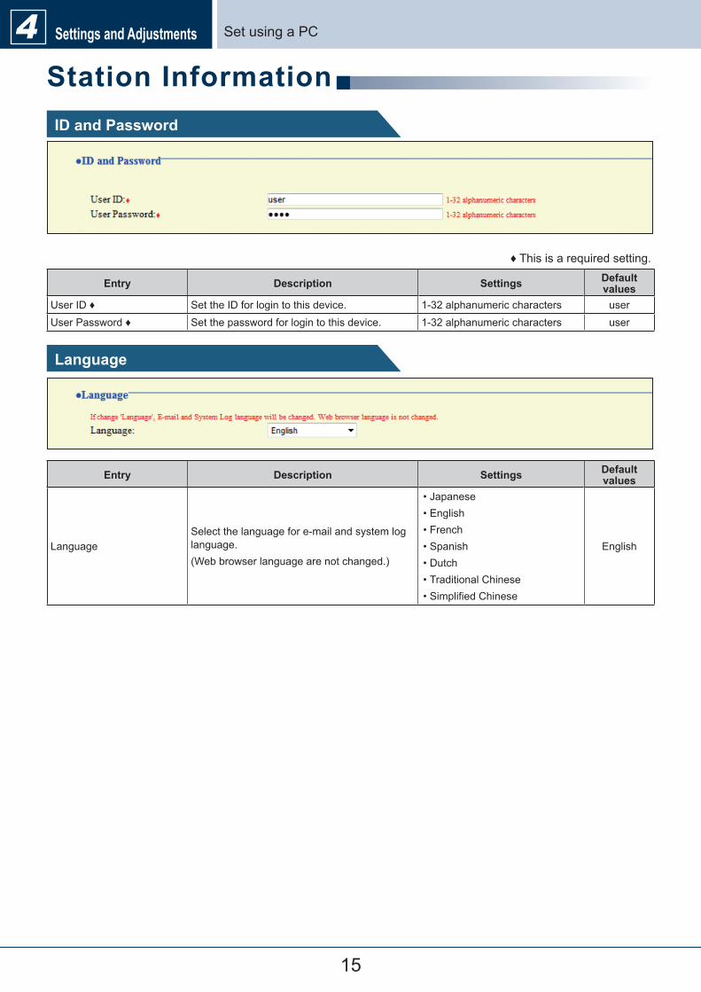
Set�using�a�PCSettings and Adjustments4Station InformationID and Password
♦�This�is�a�required�setting.
Entry Description Settings Default values
User�ID�♦ Set�the�ID�for�login�to�this�device. 1-32�alphanumeric�characters userUser�Password�♦ Set�the�password�for�login�to�this�device. 1-32�alphanumeric�characters user
Language
Entry Description Settings Default values
LanguageSelect�the�language�for�e-mail�and�system�log�language.(Web�browser�language�are�not�changed.)
•�Japanese•�English•�French•�Spanish•�Dutch•�Traditional�Chinese•�Simplified�Chinese
English
16
Set�using�a�PCSettings and Adjustments4Time
�Time Zone
Entry Description Settings Default values
Select�time�zone Select�the�time�zone�to�be�used. Select�from�99�regions
GMT-08:00�Pacific�Standard�
Time�(U.S.),�Tijuana
�Daylight Savings Time
Entry Description Settings Default values
Enable�automatic�daylight�savings�time
Adjust�the�daylight�saving�time�automatically�to�fit�the�region�selected�in�“■�Select�time�zone.”
•�Yes•�No
No
�NTP
Entry Description Settings Default values
Enable�NTPEnable�NTP�server�to�retrieve�the�time.Configuring�NTP�server�is�required�separately�if�using�an�NTP�server.�Contact�your�system�administrator.
•�Yes•�No
No
�Date and TimePressing� �will�not�show�date�and�time�settings�on�this�device.Click� �to�show�it.
Entry Description Settings Default values
Time Set�the�current�time�for�the�station.
2012/1/1/00:00:00�-�2037/12/31/23:59:59
:�Synchronized�with�the�current��time�setting�of�the�PC.
2013/1/1/�00:00:00
If�the�power�is�turned�off�for�at�least�30�minutes,�the�time�and�date�will�revert�back�to�the�default�setting.�If�this�happens,�set�the�time�and�date�again.For�this�reason,�it�is�recommended�to�use�NTP.��(Only�applicable�if�NTP�is�connected�and�set-up�with�IX�system.)
Attention
17
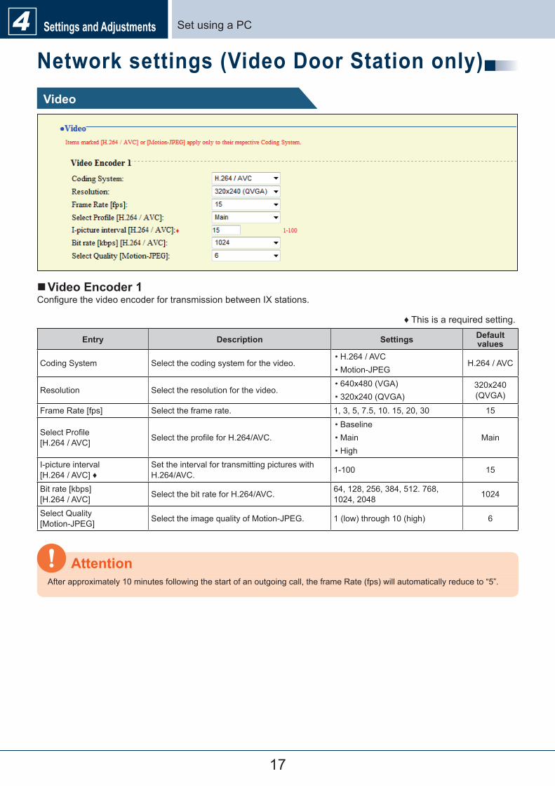
Set�using�a�PCSettings and Adjustments4Network settings (Video Door Station only)Video
�Video Encoder 1Configure�the�video�encoder�for�transmission�between�IX�stations.
♦�This�is�a�required�setting.
Entry Description Settings Default values
Coding�System Select�the�coding�system�for�the�video.•�H.264�/�AVC•�Motion-JPEG
H.264�/�AVC
Resolution Select�the�resolution�for�the�video.•�640x480�(VGA)•�320x240�(QVGA)
320x240�(QVGA)
Frame�Rate�[fps] Select�the�frame�rate. 1,�3,�5,�7.5,�10.�15,�20,�30 15
Select�Profile��[H.264�/�AVC] Select�the�profile�for�H.264/AVC.
•�Baseline•�Main•�High
Main
I-picture�interval��[H.264�/�AVC]�♦
Set�the�interval�for�transmitting�pictures�with�H.264/AVC. 1-100 15
Bit�rate�[kbps]��[H.264�/�AVC] Select�the�bit�rate�for�H.264/AVC. 64,�128,�256,�384,�512.�768,�
1024,�2048 1024
Select�Quality��[Motion-JPEG] Select�the�image�quality�of�Motion-JPEG. 1�(low)�through�10�(high) 6
After�approximately�10�minutes�following�the�start�of�an�outgoing�call,�the�frame�Rate�(fps)�will�automatically�reduce�to�“5”.
Attention
18
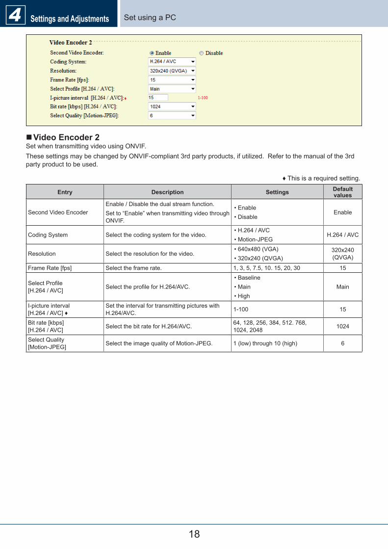
Set�using�a�PCSettings and Adjustments4
�Video Encoder 2Set�when�transmitting�video�using�ONVIF.These�settings�may�be�changed�by�ONVIF-compliant�3rd�party�products,�if�utilized.��Refer�to�the�manual�of�the�3rd�party�product�to�be�used.
♦�This�is�a�required�setting.
Entry Description Settings Default values
Second�Video�EncoderEnable�/�Disable�the�dual�stream�function.Set�to�“Enable”�when�transmitting�video�through�ONVIF.
•�Enable•�Disable
Enable
Coding�System Select�the�coding�system�for�the�video.•�H.264�/�AVC•�Motion-JPEG
H.264�/�AVC
Resolution Select�the�resolution�for�the�video.•�640x480�(VGA)•�320x240�(QVGA)
320x240�(QVGA)
Frame�Rate�[fps] Select�the�frame�rate. 1,�3,�5,�7.5,�10.�15,�20,�30 15
Select�Profile��[H.264�/�AVC] Select�the�profile�for�H.264/AVC.
•�Baseline•�Main•�High
Main
I-picture�interval��[H.264�/�AVC]�♦
Set�the�interval�for�transmitting�pictures�with�H.264/AVC. 1-100 15
Bit�rate�[kbps]��[H.264�/�AVC] Select�the�bit�rate�for�H.264/AVC. 64,�128,�256,�384,�512.�768,�
1024,�2048 1024
Select�Quality��[Motion-JPEG] Select�the�image�quality�of�Motion-JPEG. 1�(low)�through�10�(high) 6
19
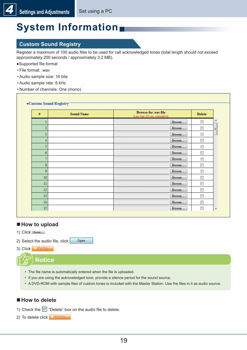
Set�using�a�PCSettings and Adjustments4System InformationCustom Sound Registry
Register�a�maximum�of�100�audio�files�to�be�used�for�call�acknowledged�tones�(total�length�should�not�exceed�approximately�200�seconds�/�approximately�3.2�MB).●Supported�file�format•�File�format:�.wav•�Audio�sample�size:�16�bits•�Audio�sample�rate:�8�kHz•�Number�of�channels:�One�(mono)
�How to upload1)�Click� .
2)�Select�the�audio�file,�click� .
3)�Click� .
•� The�file�name�is�automatically�entered�when�the�file�is�uploaded.•� If�you�are�using�the�acknowledged�tone,�provide�a�silence�period�for�the�sound�source.•� A�DVD-ROM�with�sample�files�of�custom�tones�is�included�with�the�Master�Station.�Use�the�files�in�it�as�audio�source.
Notice
�How to delete1)�Check�the� �“Delete”�box�on�the�audio�file�to�delete.
2)�To�delete�click� .
20
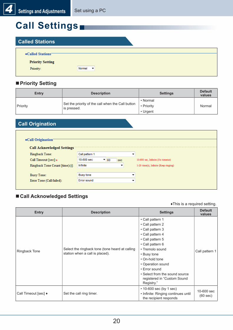
Set�using�a�PCSettings and Adjustments4Call SettingsCalled Stations
�Priority Setting
Entry Description Settings Default values
Priority Set�the�priority�of�the�call�when�the�Call�button�is�pressed.
•�Normal•�Priority•�Urgent
Normal
Call Origination
�Call Acknowledged Settings♦This�is�a�required�setting.
Entry Description Settings Default values
Ringback�Tone Select�the�ringback�tone�(tone�heard�at�calling�station�when�a�call�is�placed).
•�Call�pattern�1•�Call�pattern�2•�Call�pattern�3•�Call�pattern�4•�Call�pattern�5•�Call�pattern�6•�Tremolo�sound•�Busy�tone•�On-hold�tone•�Operation�sound•�Error�sound•�Select�from�the�sound�source�registered�in�“Custom�Sound�Registry.”
Call�pattern�1
Call�Timeout�[sec]�♦ Set�the�call�ring�timer.•�10-600�sec�(by�1�sec)•�Infinite:�Ringing�continues�until�the�recipient�responds
10-600�sec�(60�sec)
21
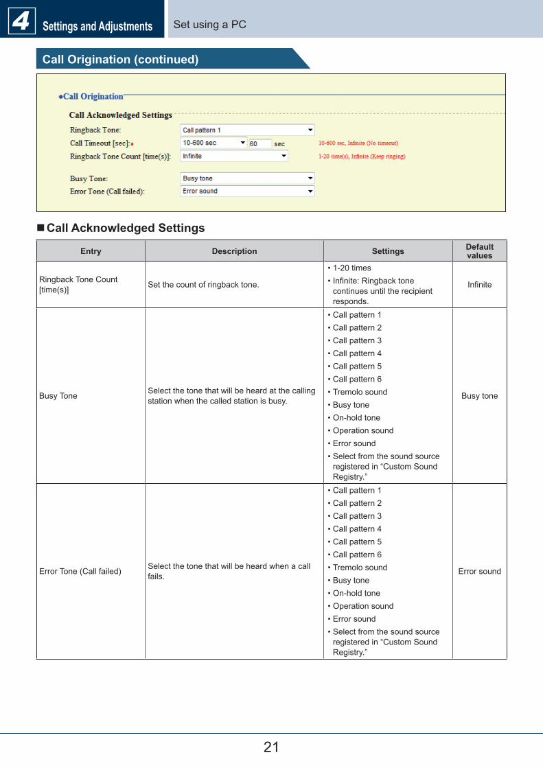
Set�using�a�PCSettings and Adjustments4Call Origination (continued)
�Call Acknowledged Settings
Entry Description Settings Default values
Ringback�Tone�Count�[time(s)] Set�the�count�of�ringback�tone.
•�1-20�times•�Infinite:�Ringback�tone�continues�until�the�recipient�responds.
Infinite
Busy�Tone Select�the�tone�that�will�be�heard�at�the�calling�station�when�the�called�station�is�busy.
•�Call�pattern�1•�Call�pattern�2•�Call�pattern�3•�Call�pattern�4•�Call�pattern�5•�Call�pattern�6•�Tremolo�sound•�Busy�tone•�On-hold�tone•�Operation�sound•�Error�sound•�Select�from�the�sound�source�registered�in�“Custom�Sound�Registry.”
Busy�tone
Error�Tone�(Call�failed) Select�the�tone�that�will�be�heard�when�a�call�fails.
•�Call�pattern�1•�Call�pattern�2•�Call�pattern�3•�Call�pattern�4•�Call�pattern�5•�Call�pattern�6•�Tremolo�sound•�Busy�tone•�On-hold�tone•�Operation�sound•�Error�sound•�Select�from�the�sound�source�registered�in�“Custom�Sound�Registry.”
Error�sound
22
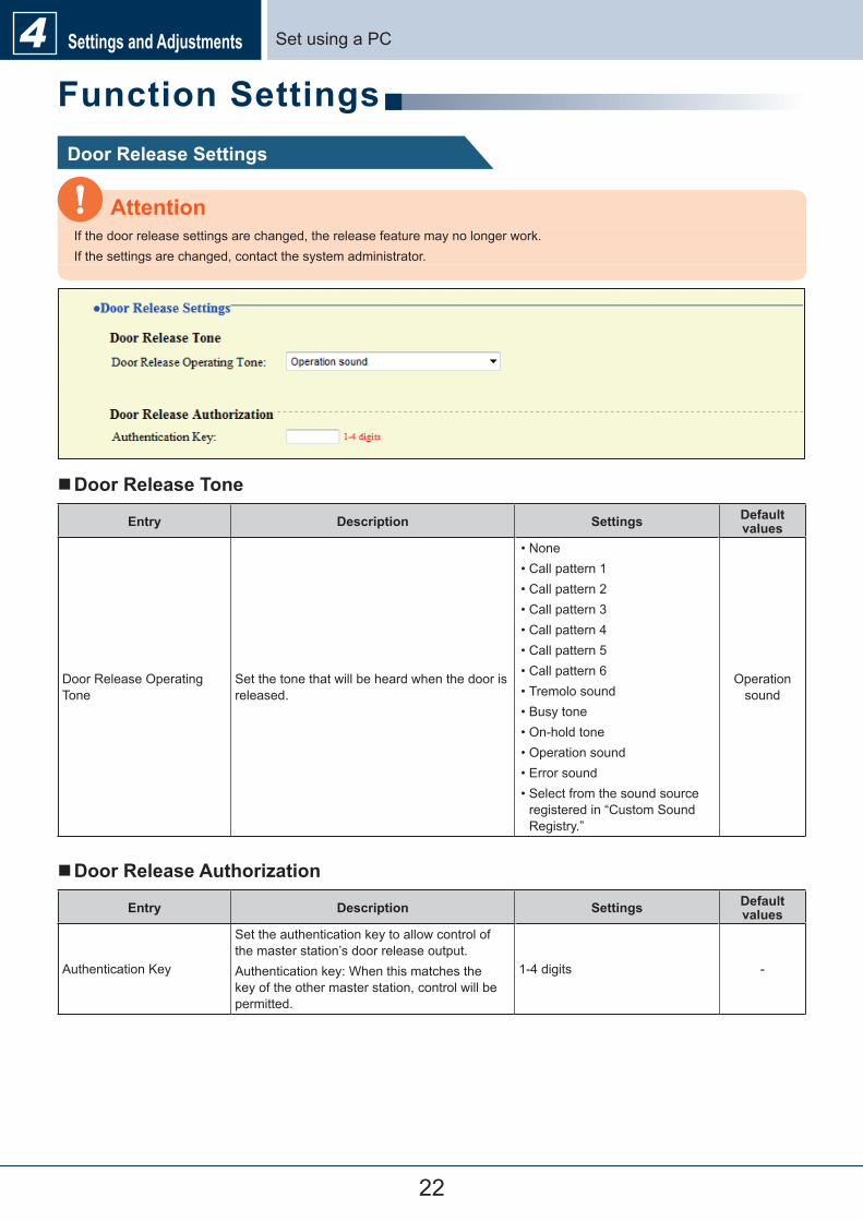
Set�using�a�PCSettings and Adjustments4Function SettingsDoor Release Settings
If�the�door�release�settings�are�changed,�the�release�feature�may�no�longer�work.If�the�settings�are�changed,�contact�the�system�administrator.
Attention
�Door Release Tone
Entry Description Settings Default values
Door�Release�Operating�Tone
Set�the�tone�that�will�be�heard�when�the�door�is�released.
•�None•�Call�pattern�1•�Call�pattern�2•�Call�pattern�3•�Call�pattern�4•�Call�pattern�5•�Call�pattern�6•�Tremolo�sound•�Busy�tone•�On-hold�tone•�Operation�sound•�Error�sound•�Select�from�the�sound�source�registered�in�“Custom�Sound�Registry.”
Operation�sound
�Door Release Authorization
Entry Description Settings Default values
Authentication�Key
Set�the�authentication�key�to�allow�control�of�the�master�station’s�door�release�output.Authentication�key:�When�this�matches�the�key�of�the�other�master�station,�control�will�be�permitted.
1-4�digits -
23
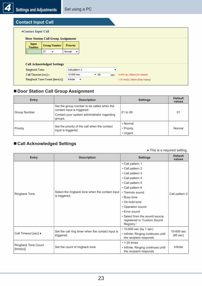
Set�using�a�PCSettings and Adjustments4Contact Input Call
�Door Station Call Group Assignment
Entry Description Settings Default values
Group�Number
Set�the�group�number�to�be�called�when�the�contact�input�is�triggered.Contact�your�system�administrator�regarding�groups.
01�to�09 01
Priority Set�the�priority�of�the�call�when�the�contact�input�is�triggered.
•�Normal•�Priority•�Urgent
Normal
�Call Acknowledged Settings♦�This�is�a�required�setting.
Entry Description Settings Default values
Ringback�Tone Select�the�ringback�tone�when�the�contact�input�is�triggered.
•�Call�pattern�1•�Call�pattern�2•�Call�pattern�3•�Call�pattern�4•�Call�pattern�5•�Call�pattern�6•�Tremolo�sound•�Busy�tone•�On-hold�tone•�Operation�sound•�Error�sound•�Select�from�the�sound�source�registered�in�“Custom�Sound�Registry.”
Call�pattern�2
Call�Timeout�[sec]�♦ Set�the�call�ring�timer�when�the�contact�input�is�triggered.
•�10-600�sec�(by�1�sec)•�Infinite:�Ringing�continues�until�the�recipient�responds
10-600�sec�(60�sec)
Ringback�Tone�Count�[time(s)] Set�the�count�of�ringback�tone.
•�1-20�times•�Infinite:�Ringing�continues�until�the�recipient�responds
Infinite
24
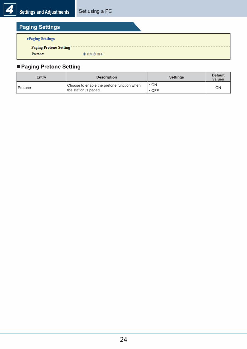
Set�using�a�PCSettings and Adjustments4Paging Settings
�Paging Pretone Setting
Entry Description Settings Default values
Pretone Choose�to�enable�the�pretone�function�when�the�station�is�paged.
•�ON•�OFF
ON
25
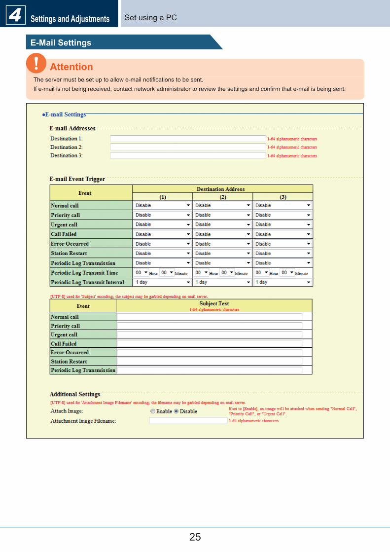
Set�using�a�PCSettings and Adjustments4E-Mail Settings
The�server�must�be�set�up�to�allow�e-mail�notifications�to�be�sent.If�e-mail�is�not�being�received,�contact�network�administrator�to�review�the�settings�and�confirm�that�e-mail�is�being�sent.
Attention
26
Set�using�a�PCSettings and Adjustments4 �E-mail Addresses
Entry Description Settings Default values
Destination�1�to�3 Set�the�e-mail�address. 1-64�alphanumeric�characters -
�E-mail Event TriggerSet�up�which�event�triggers�will�send�an�e-mail�message�for�each�address.
Entry Description Settings Default values
Normal�call An�e-mail�message�will�be�sent�when�a�normal�call�is�made.
•�Enable•�Disable
Disable
Priority�call An�e-mail�message�will�be�sent�when�a�priority�call�is�made.
•�Enable•�Disable
Disable
Urgent�call An�e-mail�message�will�be�sent�when�an�urgent�call�is�made.
•�Enable•�Disable
Disable
Call�Failed An�e-mail�message�will�be�sent�when�a�call�fails.
•�Enable•�Disable
Disable
Error�Occurred An�e-mail�message�will�be�sent�when�a�data�communication�error�occurs.
•�Enable•�Disable
Disable
Station�Restart An�e-mail�message�will�be�sent�when�the�station�is�restarted.
•�Enable•�Disable
Disable
Periodic�Log�Transmission Periodic�Log�will�be�sent�via�e-mail.•�Enable•�Disable
Disable
Periodic�Log�Transmit�Time Set�time�of�day�to�send�the�log�via�e-mail. From�00:00�to�23:59 00:00Periodic�Log�Transmit�Interval Set�how�often�the�log�will�be�sent�via�e-mail. Every�1-7�days 1�day
Configure�the�subject�of�the�e-mail�message�for�each�e-mail�event�trigger.
Entry Description Settings Default values
Subject�Text Set�the�subject�text�of�e-mail�message�for�each�trigger. 1-64�alphanumeric�characters -
�Additional Settings (Video Door Station only)
Entry Description Settings Default values
Attach�Image
Using�the�“E-mail�Event�Trigger,”�configure�the�settings�for�attaching�a�still�image�taken�by�the�Video�Door�Station�camera�to�an�e-mail,�sent�when�making�a�normal�call,�priority�call,�or�urgent�call.
•�Enable•�Disable
Disable
Attachment�Image�Filename Set�the�name�of�the�image�file�that�was�attached. 1-64�alphanumeric�characters -
UTF-8�encoding�is�used�for�the�“Subject�Text”�and�“Attachment�Image�Filename.”�Depending�on�the�e-mail�client,�the�characters�may�appear�incorrectly.
Attention
27
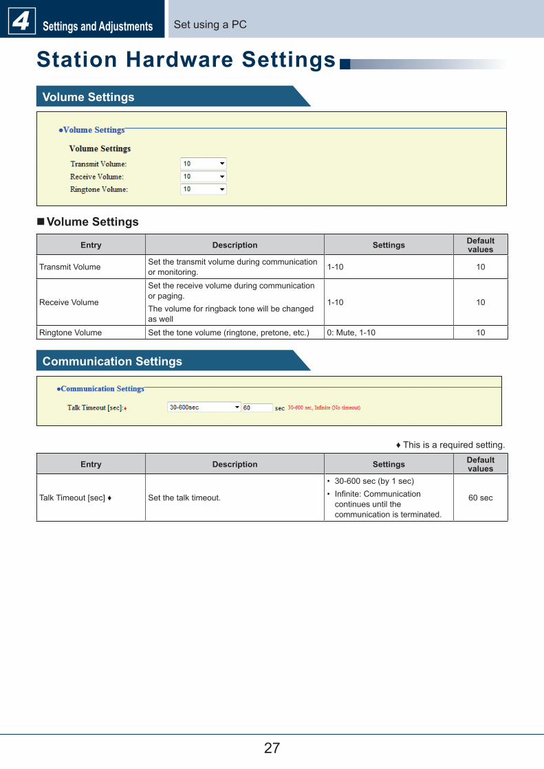
Set�using�a�PCSettings and Adjustments4Station Hardware SettingsVolume Settings
�Volume Settings
Entry Description Settings Default values
Transmit�Volume Set�the�transmit�volume�during�communication�or�monitoring. 1-10 10
Receive�Volume
Set�the�receive�volume�during�communication�or�paging.The�volume�for�ringback�tone�will�be�changed�as�well
1-10 10
Ringtone�Volume Set�the�tone�volume�(ringtone,�pretone,�etc.) 0:�Mute,�1-10 10
Communication Settings
♦�This�is�a�required�setting.
Entry Description Settings Default values
Talk�Timeout�[sec]�♦ Set�the�talk�timeout.
•� 30-600�sec�(by�1�sec)•� Infinite:�Communication�continues�until�the�communication�is�terminated.
60�sec
28
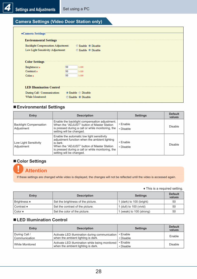
Set�using�a�PCSettings and Adjustments4Camera Settings (Video Door Station only)
�Environmental Settings
Entry Description Settings Default values
Backlight�Compensation�Adjustment
Enable�the�backlight�compensation�adjustment.When�the�“ADJUST”�button�of�Master�Station�is�pressed�during�a�call�or�while�monitoring,�the�setting�will�be�changed.
•�Enable•�Disable
Disable
Low�Light�Sensitivity�Adjustment
Enable�the�automatic�low�light�sensitivity�adjustment�function�when�the�ambient�lighting�is�dark.When�the�“ADJUST”�button�of�Master�Station�is�pressed�during�a�call�or�while�monitoring,�the�setting�will�be�changed.
•�Enable•�Disable
Disable
�Color Settings
If�these�settings�are�changed�while�video�is�displayed,�the�changes�will�not�be�reflected�until�the�video�is�accessed�again.
Attention
♦�This�is�a�required�setting.
Entry Description Settings Default values
Brightness�♦ Set�the�brightness�of�the�picture. 1�(dark)�to�100�(bright) 50Contrast�♦ Set�the�contrast�of�the�picture. 1�(dull)�to�100�(vivid) 50Color�♦ Set�the�color�of�the�picture. 1�(weak)�to�100�(strong) 50
�LED Illumination Control
Entry Description Settings Default values
During�Call�/�Communication
Activate�LED�illumination�during�communication�when�the�ambient�lighting�is�dark.
•�Enable•�Disable Enable
While�Monitored Activate�LED�illumination�while�being�monitored�when�the�ambient�lighting�is�dark.
•�Enable•�Disable Disable
29
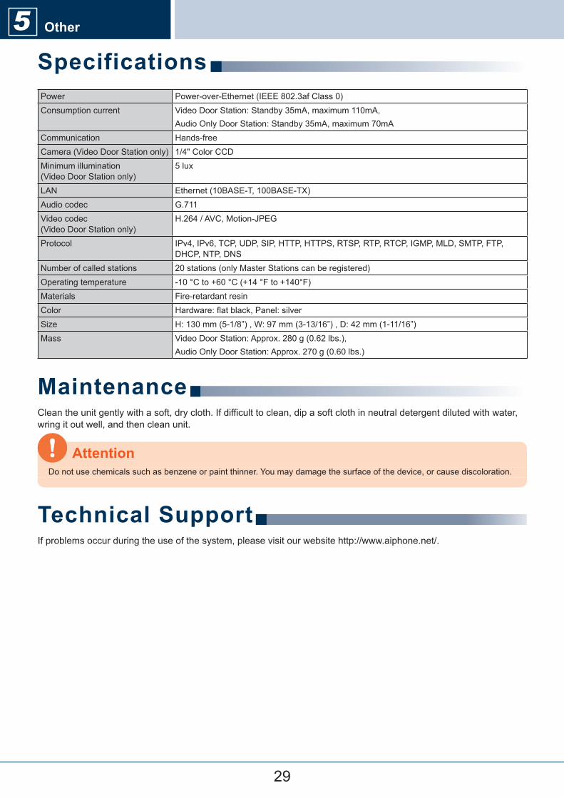
Power Power-over-Ethernet�(IEEE�802.3af�Class�0)Consumption�current Video�Door�Station:�Standby�35mA,�maximum�110mA,�
Audio�Only�Door�Station:�Standby�35mA,�maximum�70mACommunication Hands-freeCamera�(Video�Door�Station�only) 1/4"�Color�CCDMinimum�illumination��(Video�Door�Station�only)
5�lux
LAN Ethernet�(10BASE-T,�100BASE-TX)Audio�codec G.711Video�codec��(Video�Door�Station�only)
H.264�/�AVC,�Motion-JPEG
Protocol IPv4,�IPv6,�TCP,�UDP,�SIP,�HTTP,�HTTPS,�RTSP,�RTP,�RTCP,�IGMP,�MLD,�SMTP,�FTP,�DHCP,�NTP,�DNS
Number�of�called�stations 20�stations�(only�Master�Stations�can�be�registered)Operating�temperature -10�°C�to�+60�°C�(+14�°F�to�+140°F)Materials Fire-retardant�resinColor Hardware:�flat�black,�Panel:�silverSize H:�130�mm�(5-1/8”)�,�W:�97�mm�(3-13/16”)�,�D:�42�mm�(1-11/16”)Mass Video�Door�Station:�Approx.�280�g�(0.62�lbs.),�
Audio�Only�Door�Station:�Approx.�270�g�(0.60�lbs.)
MaintenanceClean�the�unit�gently�with�a�soft,�dry�cloth.�If�difficult�to�clean,�dip�a�soft�cloth�in�neutral�detergent�diluted�with�water,�wring�it�out�well,�and�then�clean�unit.
Do�not�use�chemicals�such�as�benzene�or�paint�thinner.�You�may�damage�the�surface�of�the�device,�or�cause�discoloration.
Attention
Technical SupportIf�problems�occur�during�the�use�of�the�system,�please�visit�our�website�http://www.aiphone.net/.
Specifications5 Other
30
Other5Notice regarding softwareUse�of�the�software�installed�on�this�product�has�received�direct�or�indirect�authorization�from�third�parties.
(1)GPL/LGPLThis�product�includes�software�components�subject�to�the�GPL/LGPL.Customers�can�obtain,�modify,�and�re-distribute�the�source�code�of�the�software�components�according�to�the�GPL/LGPL.Please�see�the�website�below�for�how�to�obtain�sequence�GPL/LGPL�of�this�source�code.http://www.aiphone.co.jp/data/software/source/gpl/download/ix/
Hereafter�referred�to�as�the�linkOpen�source�codeThis�product�includes�software�components�subject�to�the�GPL/LGPL,�and�customers�can�obtain,�modify,�and�re-distribute�the�source�code�of�the�software�components�according�to�the�GPL/LGPL.�In�addition,�you�can�find�details�on�the�GPL/LGPL�through�the�following�links.http://www.gnu.org/licenses/old-licenses/gpl-2.0.htmlhttp://www.gnu.org/licenses/old-licenses/lgpl-2.1.htmlPlease�confirm�the�following�contents�when�downloading.
<<Please�confirm>>■According�to�GPL/LGPL,�the�source�code�of�the�software�components�is�not�guaranteed,�including�warranty�on�“merchantability”�or�“suitability�for�a�particular�purpose.”■The�source�code�of�the�software�components�are�according�to�the�“status�quo,”�and�are�provided�based�on�the�GPL/LGPL.■Please�understand�that�we�cannot�answer�questions�regarding�the�content�of�the�source�code�of�the�software�components.
(2)OpenSSL�LicenseCopyright�(c)�1998-2011�The�OpenSSL�Project.��All�rights�reserved.Redistribution�and�use�in�source�and�binary�forms,�with�or�without�modification,�are�permitted�provided�that�the�following�conditions�are�met:1.� Redistributions�of�source�code�must�retain�the�above�copyright�notice,�this�list�of�conditions�and�the�following�
disclaimer.2.� Redistributions�in�binary�form�must�reproduce�the�above�copyright�notice,�this�list�of�conditions�and�the�following�
disclaimer�in�the�documentation�and/or�other�materials�provided�with�the�distribution.3.� All�advertising�materials�mentioning�features�or�use�of�this�software�must�display�the�following�acknowledgment:
"This�product�includes�software�developed�by�the�OpenSSL�Project�for�use�in�the�OpenSSL�Toolkit.��(http://www.openssl.org/)"
4.� The�names�"OpenSSL�Toolkit"�and�"OpenSSL�Project"�must�not�be�used�to�endorse�or�promote�products�derived�from�this�software�without�prior�written�permission.�For�written�permission,�please�contact��[email protected].
5.� Products�derived�from�this�software�may�not�be�called�"OpenSSL"�nor�may�"OpenSSL"�appear�in�their�names�without�prior�written�permission�of�the�OpenSSL�Project.
6.� Redistributions�of�any�form�whatsoever�must�retain�the�following�acknowledgment:"This�product�includes�software�developed�by�the�OpenSSL�Project�for�use�in�the�OpenSSL�Toolkit��(http://www.openssl.org/)"
THIS�SOFTWARE�IS�PROVIDED�BY�THE�OpenSSL�PROJECT�"AS�IS''�AND�ANY�EXPRESSED�OR�IMPLIED�WARRANTIES,�INCLUDING,�BUT�NOT�LIMITED�TO,�THE�IMPLIED�WARRANTIES�OF�MERCHANTABILITY�AND�FITNESS�FOR�A�PARTICULAR�PURPOSE�ARE�DISCLAIMED.��IN�NO�EVENT�SHALL�THE�OpenSSL�PROJECT�OR�ITS�CONTRIBUTORS�BE�LIABLE�FOR�ANY�DIRECT,�INDIRECT,�INCIDENTAL,�SPECIAL,�EXEMPLARY,�OR�CONSEQUENTIAL�DAMAGES�(INCLUDING,�BUT�NOT�LIMITED�TO,�PROCUREMENT�OF�SUBSTITUTE�GOODS�
31
�Other5OR�SERVICES;�LOSS�OF�USE,�DATA,�OR�PROFITS;�OR�BUSINESS�INTERRUPTION)�HOWEVER�CAUSED�AND�ON�ANY�THEORY�OF�LIABILITY,�WHETHER�IN�CONTRACT,�STRICT�LIABILITY,�OR�TORT�(INCLUDING�NEGLIGENCE�OR�OTHERWISE)�ARISING�IN�ANY�WAY�OUT�OF�THE�USE�OF�THIS�SOFTWARE,�EVEN�IF�ADVISED�OF�THE�POSSIBILITY�OF�SUCH�DAMAGE.
(3)Original�SSLeay�LicenseRedistribution�and�use�in�source�and�binary�forms,�with�or�without�modification,�are�permitted�provided�that�the�following�conditions�are�met:1.� Redistributions�of�source�code�must�retain�the�copyright�notice,�this�list�of�conditions�and�the�following�disclaimer.2.� Redistributions�in�binary�form�must�reproduce�the�above�copyright�notice,�this�list�of�conditions�and�the�following�
disclaimer�in�the�documentation�and/or�other�materials�provided�with�the�distribution.3.� All�advertising�materials�mentioning�features�or�use�of�this�software�must�display�the�following�acknowledgement:
"This�product�includes�cryptographic�software�written�by�Eric�Young�([email protected])"The�word�'cryptographic'�can�be�left�out�if�the�rouines�from�the�library�being�used�are�not�cryptographic�related�:-).
4.� If�you�include�any�Windows�specific�code�(or�a�derivative�thereof)�from�the�apps�directory�(application�code)�you�must�include�an�acknowledgement:"This�product�includes�software�written�by�Tim�Hudson�([email protected])"
THIS�SOFTWARE�IS�PROVIDED�BY�ERIC�YOUNG�"AS�IS''�AND�ANY�EXPRESS�OR�IMPLIED�WARRANTIES,�INCLUDING,�BUT�NOT�LIMITED�TO,�THE�IMPLIED�WARRANTIES�OF�MERCHANTABILITY�AND�FITNESS�FOR�A�PARTICULAR�PURPOSE�ARE�DISCLAIMED.��IN�NO�EVENT�SHALL�THE�AUTHOR�OR�CONTRIBUTORS�BE�LIABLE�FOR�ANY�DIRECT,�INDIRECT,�INCIDENTAL,�SPECIAL,�EXEMPLARY,�OR�CONSEQUENTIAL�DAMAGES�(INCLUDING,�BUT�NOT�LIMITED�TO,�PROCUREMENT�OF�SUBSTITUTE�GOODS�OR�SERVICES;�LOSS�OF�USE,�DATA,�OR�PROFITS;�OR�BUSINESS�INTERRUPTION)HOWEVER�CAUSED�AND�ON�ANY�THEORY�OF�LIABILITY,�WHETHER�IN�CONTRACT,�STRICT�LIABILITY,�OR�TORT�(INCLUDING�NEGLIGENCE�OR�OTHERWISE)�ARISING�IN�ANY�WAY�OUT�OF�THE�USE�OF�THIS�SOFTWARE,�EVEN�IF�ADVISED�OF�THE�POSSIBILITY�OF�SUCH�DAMAGE.
(4)this�software�is�based�in�part�on�the�work�of�the�Independent�JPEG�Group.
(5)this�software�is�based�in�part�on�the�work�of�the�FreeType�Team.
32
Other5WarrantyAiphone�warrants�its�products�to�be�free�from�defects�of�material�and�workmanship�under�normal�use�and�service�for�a�period�of�two�years�after�delivery�to�the�ultimate�user�and�will�repair�free�of�charge�or�replace�at�no�charge,�should�it�become�defective�upon�which�examination�shall�disclose�to�be�defective�and�under�warranty.�Aiphone�reserves�unto�itself�the�sole�right�to�make�the�final�decision�whether�there�is�a�defect�in�materials�and/or�workmanship;�and�whether�or�not�the�product�is�within�the�warranty.�This�warranty�shall�not�apply�to�any�Aiphone�product�which�has�been�subject�to�misuse,�neglect,�accident,�power�surge,�or�to�use�in�violation�of�instructions�furnished,�nor�extended�to�units�which�have�been�repaired�or�altered�outside�of�the�factory.�This�warranty�does�not�cover�batteries�or�damage�caused�by�batteries�used�in�connection�with�the�unit.�This�warranty�covers�bench�repairs�only,�and�any�repairs�must�be�made�at�the�shop�or�place�designated�in�writing�by�Aiphone.�This�warranty�is�limited�to�the�standard�specifications�listed�in�the�operation�manual.�This�warranty�does�not�cover�any�supplementary�function�of�a�third�party�product�that�is�added�by�users�or�suppliers.�Please�note�that�any�damage�or�other�issues�caused�by�failure�of�function�or�interconnection�with�Aiphone�products�is�also�not�covered�by�this�warranty.�Aiphone�will�not�be�responsible�for�any�costs�incurred�involving�on�site�service�calls.�Aiphone�will�not�provide�compensation�for�any�loss�or�damage�incurred�by�the�breakdown�or�malfunction�of�its�products�during�use,�or�for�any�consequent�inconvenience�or�losses�that�may�result.
The�object�area�of� �is�the�EU.
FCCThis�device�complies�with�Part�15�of�the�FCC�Rules.�Operation�is�subject�to�the�following�two�conditions:�(1)�this�device�may�not�cause�harmful�interference,�and�(2)�this�device�must�accept�any�interference�received,�including�interference�that�may�cause�undesired�operation.Note:�This�equipment�has�been�tested�and�found�to�comply�with�the�limits�for�a�Class�B�digital�device,�pursuant�to�Part�15�of�the�FCC�Rules.These�limits�are�designed�to�provide�reasonable�protection�against�harmful�interference�in�a�residential�installation.�This�equipment�generates,�uses,�and�can�radiate�radio�frequency�energy,�and�if�not�installed�and�used�in�accordance�with�the�instructions,�may�cause�harmful�interference�to�radio�communications.�However,�there�is�no�guarantee�that�interference�will�not�occur�in�a�particular�installation.�If�this�equipment�does�cause�harmful�interference�to�radio�or�television�reception,�which�can�be�determined�by�turning�the�equipment�off�and�on,�the�user�is�encouraged�to�try�to�correct�the�interference�by�one�or�more�of�the�following�measures:•�Reorient�or�relocate�the�receiving�antenna•�Increase�the�separation�between�the�equipment�and�receiver.•�Connect�the�equipment�to�an�outlet�on�a�circuit�different�from�that�to�which�the�receiver�is�connected.•�Consult�the�dealer�or�an�experienced�radio/TV�technician�for�help.

http://www.aiphone.net/
AIPHONE CO., LTD., NAGOYA, JAPAN
Issue Date : Nov. 2014 FK2127 A P1114 SQ 56140