Embed Size (px)
Citation preview
FRP JACKETED STEEL
UNDERGROUND STORAGE TANKS
INSTALLATION INSTRUCTIONSR923-10
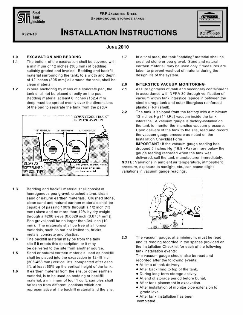
12" MINIMUM 12" MINIMUM 12" MINIMUM
JUNE 2010
1.0 EXCAVATION AND BEDDING
1.1 The bottom of the excavation shall be covered with
a minimum of 12 inches (305 mm) of bedding,
suitably graded and leveled. Bedding and backfill
material surrounding the tank, to a width and depth
of 12 inches (305 mm) all around the tank, shall be
clean material.
1.2 W here anchoring by mans of a concrete pad, the
tank shall not be placed directly on the pad.
Bedding material at least 6 inches (152.4 mm)
deep must be spread evenly over the dimensions
of the pad to separate the tank from the pad.w
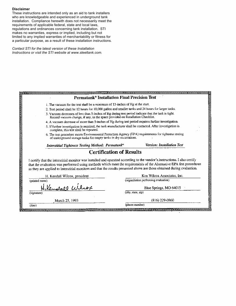
1.3 Bedding and backfill material shall consist of
homogenous pea gravel, crushed stone, clean
sand or natural earthen materials. Crushed stone,
clean sand and natural earthen materials shall be
capable of passing 100% through a 1/2 inch (13
mm) sieve and no more than 12% by dry weight
through a #200 sieve (0.0029 inch (0.0754 mm)).
Pea gravel shall be no larger than 3/4-inch (19
mm). The materials shall be free of all foreign
materials, such as but not limited to, bricks,
metals, concrete and plastics.
1.4 The backfill material may be from the tank
site if it meets this description, or it may
be delivered to the site from another source.
1.5 Sand or natural earthen materials used as backfill
shall be placed into the excavation in 12-18 inch
(305-458 mm) vertical lifts, compacted after each
lift, at least 60% up the vertical height of the tank.
1.6 If earthen material from the site, or other earthen
material, is to be used as bedding or backfill
material, a minimum of four 1 cu.ft. samples shall
be taken from different locations which are
representative of the backfill material and the site.
1.7 In a tidal area, the tank "bedding" material shall be
crushed stone or pea gravel. Sand and natural
earthen material may be used only if measures are
taken to prevent washout of material during the
design life of the system.
2.0 INTERSTICE VACUUM MONITORING
2.1 Assure tightness of tank and secondary containment
in accordance with NFPA 30 through verification of
vacuum within tank interstice (space in between the
steel storage tank and outer fiberglass reinforced
plastic (FRP) shell).
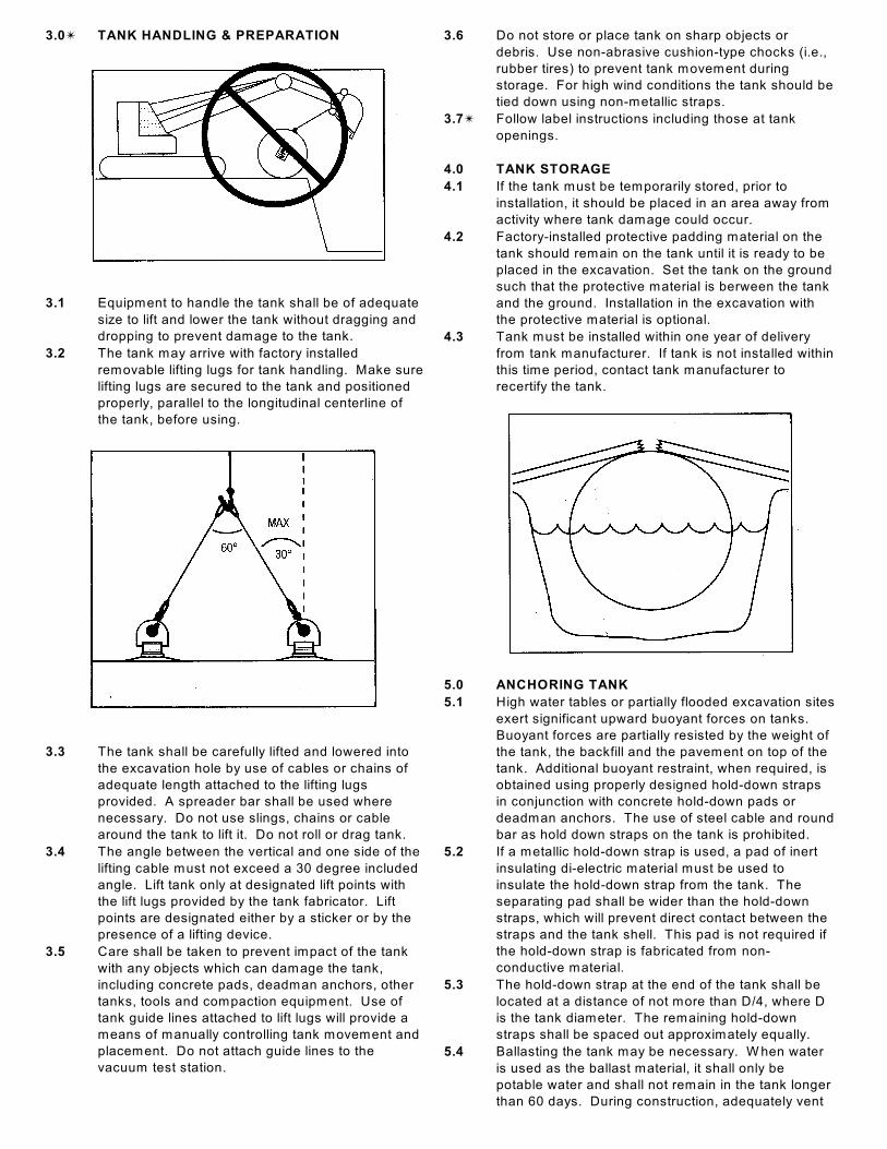
2.2 The tank is shipped from the factory with a minimum
13 inches Hg (44 kPa) vacuum inside the tank
interstice. A vacuum gauge is factory-installed on
the tank to monitor the interstice vacuum pressure.
Upon delivery of the tank to the site, read and record
the vacuum gauge pressure as noted on the
Installation Checklist Form.
IMPORTANT: If the vacuum gauge reading has
dropped 5 inches Hg (16.9 kPa) or more below the
gauge reading recorded when the tank was
delivered, call the tank manufacturer immediately.
NOTE: Variations in ambient air temperature, atmospheric
pressure, exposure to sunlight, etc., can cause slight
variations in vacuum gauge readings.
2.3 The vacuum gauge, at a minimum, must be read
and its reading recorded in the spaces provided on
the Installation Checklist for each of the following
tank installation events:
The vacuum gauge should also be read and
recorded after the following events:
! At time of tank delivery,
! After backfilling to top of the tank,
! During long-term storage activity,
! At end of storage period before burial,
! After tank placement in excavation.
! After installation of monitor pipe extension to
grade level,
! After tank installation has been
completed.
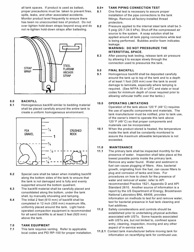
3.0u TANK HANDLING & PREPARATION
3.1 Equipment to handle the tank shall be of adequate
size to lift and lower the tank without dragging and
dropping to prevent damage to the tank.
3.2 The tank may arrive with factory installed
removable lifting lugs for tank handling. Make sure
lifting lugs are secured to the tank and positioned
properly, parallel to the longitudinal centerline of
the tank, before using.
3.3 The tank shall be carefully lifted and lowered into
the excavation hole by use of cables or chains of
adequate length attached to the lifting lugs
provided. A spreader bar shall be used where
necessary. Do not use slings, chains or cable
around the tank to lift it. Do not roll or drag tank.
3.4 The angle between the vertical and one side of the
lifting cable must not exceed a 30 degree included
angle. Lift tank only at designated lift points with
the lift lugs provided by the tank fabricator. Lift
points are designated either by a sticker or by the
presence of a lifting device.
3.5 Care shall be taken to prevent impact of the tank
with any objects which can damage the tank,
including concrete pads, deadman anchors, other
tanks, tools and compaction equipment. Use of
tank guide lines attached to lift lugs will provide a
means of manually controlling tank movement and
placement. Do not attach guide lines to the
vacuum test station.
3.6 Do not store or place tank on sharp objects or
debris. Use non-abrasive cushion-type chocks (i.e.,
rubber tires) to prevent tank movement during
storage. For high wind conditions the tank should be
tied down using non-metallic straps.
3.7u Follow label instructions including those at tank
openings.
4.0 TANK STORAGE
4.1 If the tank must be temporarily stored, prior to
installation, it should be placed in an area away from
activity where tank damage could occur.
4.2 Factory-installed protective padding material on the
tank should remain on the tank until it is ready to be
placed in the excavation. Set the tank on the ground
such that the protective material is berween the tank
and the ground. Installation in the excavation with
the protective material is optional.
4.3 Tank must be installed within one year of delivery
from tank manufacturer. If tank is not installed within
this time period, contact tank manufacturer to
recertify the tank.
5.0 ANCHORING TANK
5.1 High water tables or partially flooded excavation sites
exert significant upward buoyant forces on tanks.
Buoyant forces are partially resisted by the weight of
the tank, the backfill and the pavement on top of the
tank. Additional buoyant restraint, when required, is
obtained using properly designed hold-down straps
in conjunction with concrete hold-down pads or
deadman anchors. The use of steel cable and round
bar as hold down straps on the tank is prohibited.
5.2 If a metallic hold-down strap is used, a pad of inert
insulating di-electric material must be used to
insulate the hold-down strap from the tank. The
separating pad shall be wider than the hold-down
straps, which will prevent direct contact between the
straps and the tank shell. This pad is not required if
the hold-down strap is fabricated from non-
conductive material.
5.3 The hold-down strap at the end of the tank shall be
located at a distance of not more than D/4, where D
is the tank diameter. The remaining hold-down
straps shall be spaced out approximately equally.
5.4 Ballasting the tank may be necessary. W hen water
is used as the ballast material, it shall only be
potable water and shall not remain in the tank longer
than 60 days. During construction, adequately vent
all tank spaces. If product is used as ballast,
proper precautions must be taken to prevent fires,
spills, leaks, and other associated accidents.
Monitor product level frequently to ensure there
has been no unaccounted loss of product. Do not
over tighten hold-down straps beyond snug and do
not re-tighten hold-down straps after ballasting.
6.0 BACKFILL
6.1 Homogeneous backfill similar to bedding material
shall be placed carefully around the entire tank to
create a uniform homogeneous environment.
6.2 Special care shall be taken when installing backfill
along the bottom sides of the tank to ensure that
the tank is not damaged and is fully and evenly
supported around the bottom quadrant.
6.3 The backfill material shall be carefully placed and
consolidated along the bottom, under the tank
shell, by manually shoveling and tamping.
6.4 The initial 2 feet (610 mm) of backfill shall be
completed in 12 inch (305 mm) maximum lifts,
uniformly placed around the tank. Light hand-
operated compaction equipment is recommended
for all sand backfills to at least 3 feet (920 mm)
above the tank.
7.0 TANK EQUIPMENT
7.1 This tank requires venting. Refer to applicable
local codes and PEI RP-100 for proper installation.
8.0w TANK PIPING CONNECTION TEST
8.1 One final test is necessary to assure proper
installation of the pipe connections to the tank
fittings. Remove all factory-installed thread
protectors.
8.2 Pressure applied to the internal steel tank shall be 3-
5 psig (20.7-34.5 kPa). Shut-off the compressed air
source to the system. A soap solution shall be
applied around all tank piping connections while test
is being performed. Bubbles and/or foam indicates
leakage.
WARNING: DO NOT PRESSURIZE THE
INTERSTITIAL SPACE.
8.3 After passing leak testing, release tank air pressure
by allowing it to escape slowly through the
connection used to pressurize the tank.
9.0 FINAL BACKFILL
9.1 Homogenous backfill shall be deposited carefully
around the tank up to top of the tank and to a depth
of at least 1 foot (305 mm) over the tank to avoid
damage to laminate, especially where tamping is
required. (See NFPA 30 or UFC and state or local
codes for minimum depth of cover required prior to
allowing vehicular traffic over the tanks.)
10.0 OPERATING LIMITATIONS
Operation of the tank above 120EF (49EC) requires
the use of specific components and materials. The
tank manufacturer must be notified, prior to tank use,
of the owner’s intent to operate this tank above
120EF (49EC) so that proper components and
materials can be incorporated.
10.1 W hen the product stored is heated, the temperature
inside the tank shall be constantly monitored to
assure the maximum allowable temperature is not
exceeded.
11.0 MAINTENANCE
11.1 The primary tank shall be inspected monthly for the
presence of water. Inspection shall take place at the
lowest possible points inside the primary tank.
Remove any water found. W ater and sediment in
fuel can cause plugging of filters. Also, bacterial
growth, originating from the fuel, can cause filters to
plug and corrosion of tanks and lines. For
procedures on how to check for the presence of
water and removal of water, refer to API
recommended Practice 1621, Appendix D and API
Standard 2610. Another source of information is a
report by the US Department of Energy, Brookhaven
National Laboratory BNL 48406, provides
information on methods to test for and remove water,
test for bacterial presence in fuel tank cleaning and
fuel additives.
11.2 Safety considerations and controls should be
established prior to undertaking physical activities
associated with USTs. Some hazards associated
with USTs are, but not limited to, confined space
entry, cleaning, inspection, moving and any other
aspect of in-service work.
11.2.1 Contact tank manufacturer before moving tank for
information on recertifying tank for continued use.
DisclaimerThese instructions are intended only as an aid to tank installerswho are knowledgeable and experienced in underground tankinstallation. Compliance herewith does not necessarily meet therequirements of applicable federal, state and local laws,regulations and ordinances concerning tank installation. STImakes no warranties, express or implied, including but notlimited to any implied warranties of merchantability or fitness fora particular purpose, as a result of these installation instructions.
Contact STI for the latest version of these InstallationInstructions or visit the STI website at www.steeltank.com.
FRP JACKETED STEEL
UNDERGROUND STORAGE TANKS
INSTALLATION CHECKLIST
944 Donata Court
Lake Zurich IL 60047
Phone: 847-438-8265
Note: This checklist includes certain key steps in the proper installation of a double wall steel underground storage tank
with FRP secondary containment and is intended only as an aid to tank installers who are knowledgeable and
experienced in underground tank installation. Compliance herewith does not necessarily meet the requirements of all
applicable federal, state and local laws, regulations and ordinances concerning tank installation. TANK OW NER - A
COPY OF THIS CHECKLIST SHOULD BE RETURNED TO YOU BY THE INSTALLER FOR RETENTION W ITH
YOUR PERMANENT RECORDS.
JUNE 2010
This checklist must be completed by the installation contractor and returned to the tank owner.
Owner of Tank: Permatank Label No. ®
Location of Tank: Delivery Date: Tank Capacity: gallons(l)Installation Company: Diameter: feet(m); Length: feet (m)
Product to be stored:
! HANDLING- Lift equipment used - Lifting capacity Lbs.(Kg)- Type of chocks used if tank was stored - Describe any damage observed - Action taken
! EXCAVATION- Length Width Depth - Burial depth top of tank to grade inches(mm)- 12 inches (305 mm) minimum around each tank (Check when complete)- Burial depths meet minimum code requirements
(reference NFPA 30, UFC)NOTE: Check with tank manufacturer when burial depth exceeds5 feet.
! ANCHORING USED (Check One)Concrete Pad Deadman ORSoil and pavement overburden will hold do
(reference PEI/RP 100-90)- Number of hold-down straps Width inches(mm)- Protective pads used under straps Protective pad at least 2 inches (50 mm) wider than width ofhold-down strap, or wrap around type pad used - 1 foot (304 mm) of backfill material under tank OR- 6 inch (152 mm) separation when concrete pad is used
! BACKFILL- Material: clean sand pea gravel #8 stone - Depth of homogenous material beneath tank inches- Backfill has been placed to ensure full support along the tank'sbottom quadrant
! TANK PIPING CONNECTION TEST- Pipe fittings air-tested at 5 psig (34.5 kPa) while applying soapsolution onto fittings to check for leaks
! INTERSTITIAL VACUUM GAUGE READINGS AT:Tank Delivery inches (kPa) of Hg Date:
Driver signature Installer signature Date:
after backfill to tank top inches (kPa) of Hg Other readings obtained inches (kPa) of Hg
(Signature of Installing Foreman or Project Engineer)
! PIPING USED (Check all that apply)Non-conductive Metallic Secondary containment used Flexible Was monitoring pipe extension installed?Yes No
(Signature of Installing Foreman or Project Engineer)
! COMMENTS:
TANK OWNER'S MAILING ADDRESS:Street City State Zip Telephone
R923-10
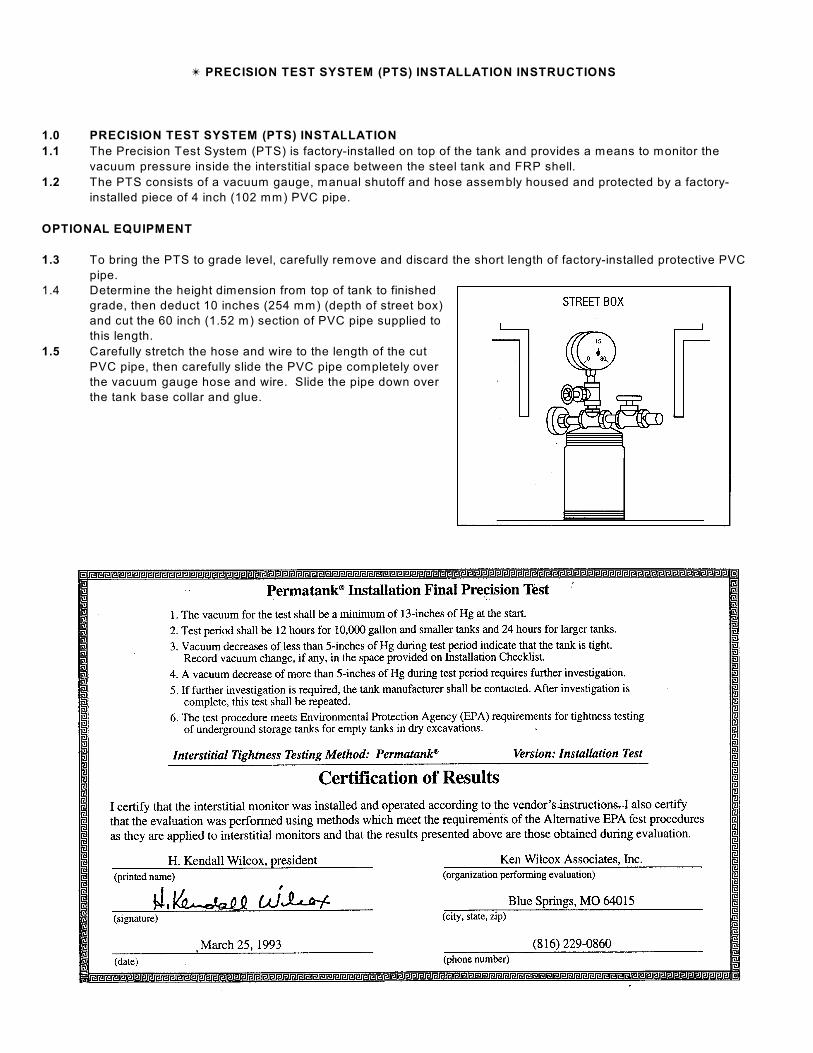
u PRECISION TEST SYSTEM (PTS) INSTALLATION INSTRUCTIONS
1.0 PRECISION TEST SYSTEM (PTS) INSTALLATION
1.1 The Precision Test System (PTS) is factory-installed on top of the tank and provides a means to monitor the
vacuum pressure inside the interstitial space between the steel tank and FRP shell.
1.2 The PTS consists of a vacuum gauge, manual shutoff and hose assembly housed and protected by a factory-
installed piece of 4 inch (102 mm) PVC pipe.
OPTIONAL EQUIPMENT
1.3 To bring the PTS to grade level, carefully remove and discard the short length of factory-installed protective PVC
pipe.
1.4 Determine the height dimension from top of tank to finished
grade, then deduct 10 inches (254 mm) (depth of street box)
and cut the 60 inch (1.52 m) section of PVC pipe supplied to
this length.
1.5 Carefully stretch the hose and wire to the length of the cut
PVC pipe, then carefully slide the PVC pipe completely over
the vacuum gauge hose and wire. Slide the pipe down over
the tank base collar and glue.