Embed Size (px)
Citation preview

For United States Government Use Only
UNITED ST ATES DEPARTMENT OF THE INTERIOR
BUREAU OF RECLAMATION
. ~ .. -- - ~.J - - - .,..,..~~, -;•
INVESTIGATION OF AN 8-INCH PROPELLER METER
Report No. Hyd-558
Hydraulics Branch DIVISION OF RESEARCH
OFFICE OF CHIEF ENGINEER DENVER, COLORADO
August 29, 1966

IMPORTANT NOTICE
The contents of this document may not be disclosed to persons outside the United States Government without special authorization. Any requests from others to inspect or utilize this document should be referred to the Chief Research Scientist.

CONTENTS
Abstract . . . . . . . . . . . . . . . . . . . . . . . . . . . . . . . . . . . . . . . . . . . . . . . iii Summary ............................................. . Introduction ........................................... . Calibration Facilities .................................. .
1 2 2
Meter............................................... 2 Meter Test Facility . . . . . . . . . . . . . . . . . . . . . . . . . . . . . . . . . . 3
Calibration Procedure. . . . . . . . . . . . . . . . . . . . . . . . . . . . . . . . . . . 3 Test Series . . . . . . . . . . . . . . . . . . . . . . . . . . . . . . . . . . . . . . . . . . . . 3 Discussion of Results . . . . . . . . . . . . . . . . . . . . . . . . . . . . . . . . . . . 4 Conclusions . . . . . . . . . . . . . . . . . . . . . . . . . . . . . . . . . . . . . . . . . . . . 5
Figure
Eight-inch Saddle-type Propeller Meter . . . . . . . . . . . . . . . . . 1 Laboratory Test Facility and Meter Installation . . . . . . . . . . . 2 Meter Installation Downstream of goo Elbow . . . . . . . . . . . . . . 3 Meter Calibration Curves--Effect of Pipe Size
on Calibration . . . . . . . . . . . . . . . . . . . . . . . . . . . . . . . . . . . . . . . 4 Meter Calibration Curves - - Effect of Flow Straighteners
on Registration . . . . . . . . . . . . . . . . . . . . . . . . . . . . . . . . . . . . . . 5 Meter Calibration Curves - - Meter Installed Downstream
of goo Elbow . . . . . . . . . . . . . . . . . . . . . . . . . . . . . . . . . . . . . . . . . 6 Effect of Pipe Area on Meter Registration . . . . . . . . . . . . . . . . 7
i

CONTENTS
Abstract . . . . . . . . . . . . . . . . . . . . . . . . . . . . . . . . . . . . . . . . . . . . . . . iii Summary ............................................. . Introduction . . . . . . . . . . . . . . . . . . ......................... . Calibration Facilities .................................. .
1 2 2
Meter. . . . . . . . . . . . . . . . . . . . . . . . . . . . . . . . . . . . . . . . . . . . . . . 2 Meter Test Facility . . . . . . . . . . . . . . . . . . . . . . . . . . . . . . . . . . 3
Calibration Procedure. . . . . . . . . . . . . . . . . . . . . . . . . . . . . . . . . . . 3 Test Series . . . . . . . . . . . . . . . . . . . . . . . . . . . . . . . . . . . . . . . . . . . . 3 Discussion of Results . . . . . . . . . . . . . . . . . . . . . . . . . . . . . . . . . . . 4 Conclusions ............................ 0 • • • • • • • • • • • • • • • 5
Figure
Eight-inch Saddle-type Propeller Meter . . . . . . . . . . . . . . . . . 1 Laboratory Test Facility and Meter Installation . . . . . . . . . . . 2 Meter Installation Downstream of 90° Elbow . . . . . . . . . . . . . . 3 Meter Calibration Curves--Effect of Pipe Size
on Calibration . . . . . . . . . . . . . . . . . . . . . . . . . . . . . . . . . . . . . . . 4 Meter Calibration Curves- -Effect of Flow Straighteners
on Registration . . . . . . . . . . . . . . . . . . . . . . . . . . . . . . . . . . . . . . 5 Meter Calibration Curves - - Meter Installed Downstream
of 90° Elbow . . . . . . . . . . . . . . . . . . . . . . . . . . . . . . . . . . . . . . . . . 6 Effect of Pipe Area on Meter Registration . . . . . . . . . . . . . . . . 7
i

ABSTRACT
An 8-in. saddle-type propeller meter was calibrated in the laboratory for normal installation with 30 diameters of straight pipe upstream of the meter and for a severe test of accuracy with the meter installed 6 diameters downstream of a 90 deg mitered elbow. Discharges indicated by the propeller meter, obtained by timing the totalizer register in the meter head, were compared to values obtained simultaneously using the Venturi meters installed in the hydraulics laboratory for use as measuring devices. The Venturi meters, volumetrically calibrated, are accurate to within ±o. 5% of the actual flow. The meter was tested in 2 different sizes of pipe, and the effect of flow straighteners on the meter accuracy was investigated. For the normal installation with flow straighteners, the meter accuracy was ±2% for discharges between 0. 55 to 3. 33 cfs; but the accuracy decreased in the lower range of 0. 22 to 0. 55 cfs. For the meter downstream of the elbow, the accuracy was ±2% for discharges from 0. 65 to 3. 33 cfs. In both installations. the meter read as much as 13% low at the minimum-rated discharge of 0. 22 cfs. Flow straighteners increased the meter accuracy by as much as 1. 5% in both installations. Tests of the meter in 2 -sizes of pipe showed best accuracy when the inside diameter of the pipe was 8. 00 in.
DESCRIPTORS-- *meters/ current meters/ *flow meters/ velocity meters/ Venturi meters/ *water meters/ closed conduits/ hydraulics/ pipelines/ water pipes/ *water measurement/ *laboratory tests/ fluid flow/ research and development/ irrigation/ discharges IDENTIFIERS- - *flow straighteners/ *propeller meters FOR UNITED STATES GOVERNMENT USE ONLY
iii

UNITED STATES DEPARTMENT OF THE INTERIOR
BUREAU OF RECLAMATION
Office of Chief Engineer Division of Research Hydraulics Branch Special Investigations Section Denver. Colorado August 29, 1966
Laboratory Report No. Hyd-558 Compiled by: C. E. Brockway Checked by: J. C. Schuster Reviewed by: A. J. Peterka Submitted by: H. M. Martin
INVESTIGATION OF AN 8-INCH PROPELLER METER
SUMMARY
The discharge characteristics of a new 8-inch saddle-type propeller meter, Figure 1, were investigated in the hydraulics laboratory as part of the Bureau of Reclamation's water measurement program for evaluating and developing water-measuring methods and devices.
Discharge measurement . .accuracy and operating chara~teristics were determined for the meter in two pipelines of different inside diameters. In one series of measurements, there were 30 diameters of straight pipe upstream of the meter in both lines. In a second test series, the discharge characteristics were determined for the meter installed 6 pipe diameters downstream of a 90° mitered elbow. The change in the accuracy of the meter was determined with and without the flow straighteners supplied with the meter in both test series.
The discharge through the propeller meter was measured by volumetrically calibrated Venturi meters. The meters installed in the Hydraulic Laboratory for use as measuring devices, are accurate to within plus or minus 0. 5 percent. A discharge ratio, indicated propeller meter discharge divided by the measured discharge through the pipeline, was used as a measure of the accuracy of the meter for both installations. Calibration curves were drawn as best-fit lines through points plotted using the discharge ratio as the ordinate and the Venturi meter (actual) discharge as the abscissa, Figure 4, 5, and 6.
A meter accuracy within plus or minus 2 percent of the actual flow was obtained for discharges between O. 55 and 3. 33 cfs (cubic feet per second) (245 to 1,500 gallons per minute). The meter was installed with flow straighteners in a 7. 97-inch-diameter pipe and had 30 diameters of straight pipe upstream of the meter, Figure 4, Curve 2. The meter accuracy decreased rapidly for discharges less than O. 55 cfs. At the manufacturer's minimum rated discharge of 0. 22 cfs, the accuracy of the meter used in this study could not be accurately measured. A 90° elbow installed about 6 diameters upstream from the propeller reduced

the meter registration by 1. 7 percent in the 7. 97 -inch pipe, Figures 3 and 6. Flow straighteners upstream of the propeller increased the accuracy by about 1. 5 percent in both meter installations. Installation of the meter in a pipe of less than 8. 0 inches inside diameter causes the meter to overregister. For a slightly undersized pipe, 7. 78 inches inside diameter, the meter registers about 7 percent too high (Curve 1, Figure 4). A pipe diameter ·of 7. 97 inches caused about 1. 2 percent overregistration (Figure 5, Curve 1).
INTRODUCTION
The need for accurate and reliable water-measuring devices is becoming more evident as the use of irrigation water increases. As more and more land is placed under irrigation, the demand for water increases, necessitating a complete and accurate accounting of the flow from the main diversion structure to the farm turnout. The Bureau of Reclamation conducts a water measurement program for the purpose of evaluating new and existing flow -measuring devices to find better methods and improve the accuracy of water measurement.
-The calibration of an 8-inch saddle-type propeller meter was performed in the Hydraulic Branch of the Bureau of Reclamation as part of the water measurement program.
CALIBRATION FACILITIES
Meter
The meter used for calibration studies was an 8-inch saddle-type propeller meter, of a type used in many irrigation districts and readily available for purchase (Figure lA). The 7-inch-diameter plastic propeller and shaft housing was inserted into the pipe through a 5-inch-square hole cut into the crown of the pipe. The meter cover plate was sealed to the pipe against a rubber gasket using the three U-bolts which are a part of the meter assembly.
All of the metal parts of the meter except the packing unit on the propeller 'Shaft and the meter head were coated by the manufacturer with a tough pliable plastic. The meter head contained a flow totalizing register that could be read to the nearest 0. 0001 acrefoot (43. 56 cubic feet). An instantaneous flow rate needle and dial graduated in increments of 100 gallons per minute was included in the register, Figure 18. The rated range.of the meter according to the manufacturer's catalog is 100 to L 500 gallons per minute ( 0. 2 2 to 3 . 3 cf s).
2
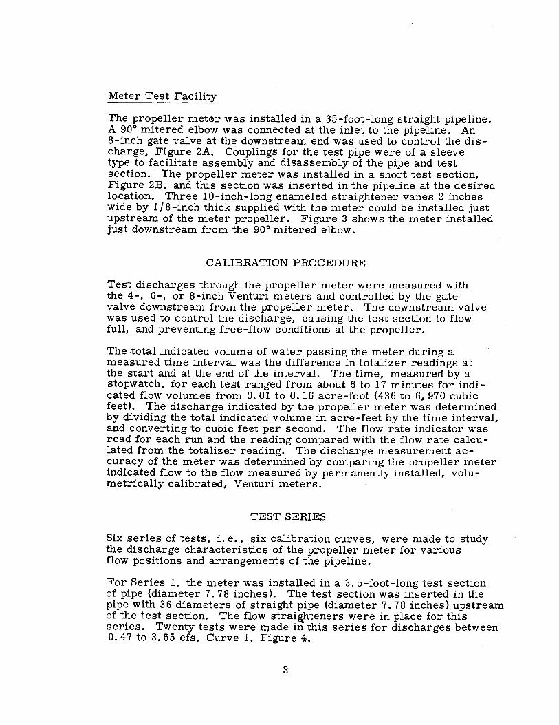
Meter Test Facility
The propeller meter was installed in a 35-foot-long straight pipeline. A 90° mitered elbow was connected at the inlet to the pipeline. An 8-inch gate valve at the downstream end was used to control the discharge. Figure 2A. Couplings for the test pipe were of a sleeve type to facilitate assembly and disassembly of the pipe and test section. The propeller meter was installed in a short test section. Figure 2B, and this section was inserted in the pipeline at the desired location. Three 10-inch-long enameled straightener vanes 2 inches wide by 1 / 8-inch thick supplied with the meter could be installed just upstream of the meter propeller. Figure 3 shows the meter installed just downstream from the 90° mitered elbow.
CALIBRATION PROCEDURE
Test discharges through the propeller meter were measured with the 4-. 6-. or 8-inch Venturi meters and controlled by the gate valve downstream from the propeller meter. The dQwnstream valve was used to control the discharge. causing the test section to flow full, and preventing free-flow conditions at the propeller.
The -total indicated volume of water passing the meter during a measured time interval was the difference in totalizer readings at the start and at the end of the interval. The time. measured by a stopwatch, for each test ranged from about 6 to 17 minutes for indicated flow volumes from 0. 01 to 0. 16 acre-foot (436 to 61 970 ·cubic feet). The discharge indicated by the propeller meter was determined by dividing the total indicated volume in acre-feet by the time interval. and converting to cubic feet per second. The flow rate indicator was read for each run and the reading compared with the flow rate calculated from the totalizer reading. The discharge measurement accuracy of the meter was determined by comparing the propeller meter indicated flow to the flow measured by permanently installed. volumetrically calibrated, Venturi meters.
TEST SERIES
Six series of tests. i.e .• six calibration curves, were made to study the discharge characteristics of the propeller meter for various flow positions and arrangements of the pipeline.
For Series 1, the meter was installed in a 3. 5-foot-long test section of pipe (diameter 7. 78 inches). The test section was inserted in the pipe with 36 diameters of straight pipe (diameter 7. 78 inches) upstream of the test section. The flow strai~hteners were in place for this series. Twenty tests were made in this series for discharges between O. 47 to 3. 55 cfs. Curve 1 •. Figure 4.
3

A 5-foot section of 7. 97 -inch-diameter pipe was used as the test section for Series 2 with 30 diameters of straight pipe (diameter 7. 78 inches) upstream of the test section. Flow straighteners were in place for the series. Eighteen tests were made in Series 2 for discharges ranging from O. 32 to 3. 35 cfs, Curve 2, Figure 4.
Series 3 was similar to Series 2 except the 30 diameters of straight pipe upstream of the test section had a diameter of 7. 97 inches or the same diameter as the test section. Twenty tests, 0. 40 to 3. 27 cfs, with flow straighteners installed were performed, Curve 1, Figure 5.
In Series 4, the 5-foot-long test section of 7. 97-inch pipe and 30 diameters of the same diameter pipe upstream of the test section were installed, but the flow straighteners were not in place. The calibration curve for Series 4 is Curve 2, Figure 5.
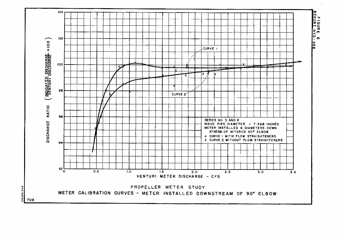
For Series 5 and 6, the 5-foot test section was installed downstream from a 90° mitered elbow of the same diameter as the test section (7. 97 inches). The test section was installed 16 inches downstream of the elbow thereby placing the propeller about 6 diameters downstream of the elbow, Figure 3B. The flow straighteners were in place for Test Series 6, Curve 1, Figure 6, but were not installed for Series 5, Curve 2.
DISCUSSION OF RESULTS
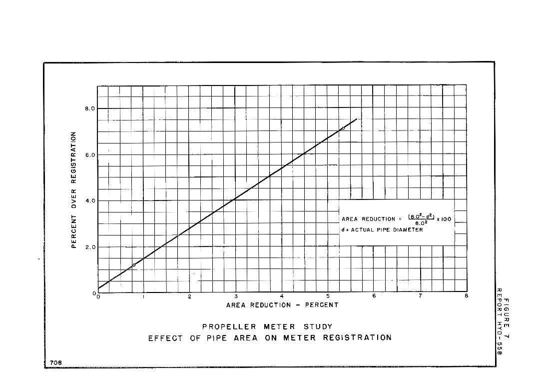
Results from Test Series 1, for which the pipe diameter was 7l78 inches, show a registration of about 107 percent for: discharges larger than 1. 0 cfs, Curve 1, Figure 4. Available literature from the manufacturer on installation of this meter did not indicate that an 8-inch-inside-diameter pipe is required or specify the allowable thickness of wall pipe. If an 8-inch-inside-diameter pipe is the design diameter, than the 7. 78-inch-diameter pipe has a flow area 5. 33 percent less than the design area. This area correction would help to offset the overregistration characteristics of the meter.
To investigate the effect of pipe diameter on the registration of the meter, Series 2, was performed using a test section diameter equal to 7. 97 inches. The calibration curve for Series 2 shows a registration of about 101. 2 percent for discharges above 1. 0 cfs. The 7. 97-inch pipe has a flow area 0. 80 percent less than an 8-inch-inside-diameter pipe.
A third pipe with a diameter different from the two pipes tested was not available to determine whether the percent of overregistration for discharges over 1. 0 cfs and pipe area reduction for the two pipes tested. Figure 7 indicates that for zero overregistration, the inside diameter of the pipe should be about 8. 01 inches.
4

Test Series 3 and 4 determined (1) the measurement accuracy of the meter for 30 diameters of 7. 97-inch-inside-diameter straight pipe upstream and (2) the effect of flow straighteners on the registration of the meter, Curves 1 and 2, Figure 5. Series 3, with flow straighteners, shows a registration of from 101 to 101. 7 percent for discharges exceeding 1. 0 cfs. Without flow straighteners. the meter registered about 102. 5 percent of the actual discharge. Information available from the manufacturer did not indicate the accuracy sp~cifications for this meter. but the general specification for propeller meters of this type is plus or minus 2 percent over the rated range of discharges. Discharge ratios between 98 and 102 would fall within the plus or minus 2 percent accuracy range. For this meter with flow straighteners installed in a pipe of diameter 7. 97 inches, the ' plus or minus 2 percent accuracy is achieved for discharges from 0. 55 to 3. 5 cfs. Figure 5. For discharges less than 0. 55 cfs, the dischargy ratio decreases rapidly and at the manufacturer's recommended minimum flow (0. 22 cfs) the discharge ratio could not be accurately ,measured. The propeller of this meter did not rotate when the discharge was 0. 18 or O. 04 cfs less than the manuf~,cturer's minimum discharge.
In Series 5 and 6, the meter was installed downstream from a 90° elbow to study the effect of the elbow on the meter registration with and without flow straighteners. The calibration curves resulting from Series 5 and 6,,, Figure 6, show that the registrations are lower for the meter installed downstream of the elbow than for the meter with 30 diameters of straight pipe upstream. With flow straighteners installed, the registration is abbut 99. 5 to 100 for discharges greater than 0. 8 cfs with the sharp decrease in registration for discharges below 0. 8 cfs. ,, ·
For the meter dow,nstream of the elbow without flow straighteners. the registration is b~tween O and 1. 5 percent lower than with flow straightenyrs. . '
CONCLUSIONS
The results and conclusions presented in this report were obtained from a series of tests performed on one new propeller meter and are indicative of the performance of this r:p.eter. Extrapolation of these results to other propeller meters of the same type may not be valid. No attempt was made to evaluate the meter reliability or performance on a long-term basis. To fully evaluate the meter. additional tests after 2 or 3 years of field operation would be required.
1. The 8-inch saddle-type propeller meter investigated in this study and installed in a 7. 97 -inch-inside-diameter pipe, with flow straighteners and 30 diameters of straight pipe upstream of the meter.
5

indicated discharges with an accuracy of plus or minus 2 percent between: 0. 55 and 3. 33 cfs (245 to 1, 500 gallons per minute).
2. For discharges below 0. 55 cfs. the accuracy decreased rapidly and at the manufacturer's minimum recommended discharge. 0. 22 cfs, the meter registration could not be accurately measured.
3. Flow straighteners increased the registration of the meter by as much as 1. 5 percent. both for the meter installed with 30 diameters of straight pipe upstream and for the meter installed downstream of a a 90° elbow.
4. The meter registered about 1. 7 percent less discharge when installed downstream of a 90° elbow than when installed with 30 diameters of straight pipe upstream of the meter.
5. The meter gave best accuracy when installed with flow straighteners in a pipe of 7. 97-inch inside diameter. Smaller diameters caused the meter to overregister.
6

PX -D-46900 NA
P X -D-54975 NA
A. Eight-inch propeller meter used for laboratory calibration.
B. Propeller meter showing totalizer register and flow rate indicator .
PROPELLER METER STUDY Eight-inch Saddle-type Propeller Meter
Figure 1 Report Hyd-558

Figure 2 Report Hyd-558
-
P X- D - 54978 NA
A. Laboratory facility for propeller meter calibration.
PX-0-54979 NA
B. Eight-inch pipe test section with meter installed.
PROPELLER METER STUDY Laboratory Test Facility and Meter Installation

P X- D-5497 6 N A
A. Laboratory facility with meter installed downstream of goo elbow .
B. Meter installed downstream of go 0 elbow.
PROPELLER METER STUDY Meter Installation Downstream of goo Elbow
Figure 3 Report Hyd-558

108
0 AO ~ I:>
/"' "--- r, 0 ~
I ,
, ;'
--p CURVE I- --
,,.--... 106 0 0
' I SERIES NO I c I INSIDE PIPE DIAMETER = 7. 784 INCHES
)C
LI.I LI.I <.!) <.!)
a:: a:: <I: <I: 104 J:J: 00 ~en 0-
0
30 DIAMETERS OF STRAIGHT PIPE I UPSTREAM OF METER
I FLOW STRAIGHTENERS INSTALLED
I
0 o_ LI.I a:: I-::, <I: I-~z 102 OLIJ ?:>
I -I j
---- ' ,. l
...,i.« I.,( ,~
0 ,v , , --I-<I: a:: 100
y -CURVE 2 --
LL.I ' SERIES. NO. 2 (!)
a:: <( ::c 0 V,
0 98
I INSIDE PIPE DIAMETER ; 7. 968 INCHES 30 DIAMETERS OF 7. 784 INCH PIPE I
UPSTREAM OF METER FLOW STRAIGHTENERS INSTALLED 0 )
I I '
0.5 1.0 1.5 2.0 2.5 3.0
VEN TURI METER DISCHARGE - CFS
PROPELLER METER STUDY METER CALIBRATION CURVES - EFFECT OF PIPE SIZE ON CALIBRATION
/08
r,
-,_
~
u
,__..
~
I--
3.5
:II fT1 ,, "Tl o::u (j) -i C:
:JJ ~!Tl 0 I .,.
UI UI a,

-0 0
><
I.LI I.LI (!) (!) a:: a:: <(<( J: J: Oo !!! Cl) o-
C o_ I.LI a:: I- :::::, <( I-2z CI.LI z>
----0 I-<( a::
I.LI (!)
a:: <( J: 0 Cl)
C
708
104
,CURVE 2
X 1,'
X _,, -
102 ~i,...,-
A
X
/ J""" ~
~ -)/' ..,v 0 0 "
~ lo 0
I V 0 -, ' ,
100
, V
, ,
CURVE I'
I I I /'
It. i' 98
I --.,
I
J I , 'l
j
I 96
SERIES NO. 3 AND 4 INSIDE PIPE DIAMETER = 7. 968 INCHES 30 DIAMETERS OF 7. 968 INCH PIPE
UPSTREAM OF METER
0 CURVE I WITH FLOW STRAIGHTEN_ERS
94 X CURVE 2 WITHOUT FLOW STRAIGHTENERS
0.5 1.0 I. 5 2.0 2.5 3.0
VENTURI METER DISCHARGE CFS
PROPELLER METER STUDY METER CALIBRATION CURVES - EFFECT OF FLOW STRAIGHTENERS ON REGISTRATION
.,__
,__
"--
3.5
;o ITI ,, .,, o;o Ci)
-IC ::ti
~1"1
~(JI
(JI
(JI
CD
GI. ,, 0 .. '" "' ,;, ., 708
104
--. 102 0 0
><
0 let a:: 96
IJJ <.!)
a:: ct ::c 0 Cl)
0 94
j
I I
J / I I 'J I
'
-
1;--~ I ~
V ~ ~
V v ~
,CURVE I ,, ,
/
I
.. y
- I
Ix
X X ' X I
I /
I ,, ,, ,
CURVE 2""
SERIES NO. 5 AND 6 INSIDE PIPE DIAMETER = 7. 968 INCHES METER INSTALLED 6 DIAMETERS DOWN
STREAM OF MITERED 90° ELBOW 0 CURVE I WITH FLOW STRAIGHTENERS X CURVE 2 WITHOUT FLOW STRAIGHTENERS
0.5 1.0 1.5 2.0 2.5 3.0
VENTURI METER DISCHARGE - CFS
PROPELLER METER CALIBRATION CURVES - METER
METER STUDY INSTALLED DOWNSTREAM OF 90° ELBOW
~
1--
1--
1--
3.5
::u ITI '11 ...,
o::u Ci) -IC
::u !m 00) I
8.0
z 0 .... <(
a:: 6.0 .... er, (!)
w a:: a:: w > 4.0 0
.... z w (.)
a:: LLJ a. 2.0
,..V l/
, /
708
~ ,
~ /
l/ ,
/ V
/ I"
/ V
v---/
/
V AREA REDUCTION = <e,02-d21 x ioo
V e.o 2
/ d = ACTUAL PIPE DIAMETER
,; V /
V
2 3 4 5 6 7
AREA REDUCTION - PERCENT
PROPELLER METER STUDY
EFFECT OF PIPE AREA ON METER REGISTRATION
,__
-,__
8 ::0 rr1 -0 "Tl o::0 G> ..;c
:::0 Irri -< 0-..1 I
c.n c.n CD

7-1750 (tCl-64)
OONVF.RSION FACTORS-BRITISH TO METRIC UNITS OF MEASUREMENT
The f'olloriDg conversion factors adopted b,Y the Bureau of' Reclamation are those published b,Y the .Amerlcan Society for TestiJlg and Materials (.AS'!M Metric Practice Guide, January 1964) except that additional factors (*) CCXIIJllOncy used in the Bureau have been added. Further discussion of' def'initions of' quantities and units is given on pages 10-11 of the Alfflll Metric Practice Guide.
The metric units and conversion factors adopted b,Y the .AS'JM are based on the "International &,ystem of Units" (designated SI for &,ysteme International d 1Unites), i'ixed b,Y the International Oommittee for Weights and Measures; this system is also lmolln as the Giorgi or Ml!SA (meter-kilogram (mass)-second-u,pere) system. This system has been adopted b,Y the International OrgaDization for standardization in ISO Recaamendation R-.'.31.
The metric technical unit of' force is the kilogram-force; this is the force which, when applied to a bod;y haviJlg a mass of' 1 kg, g1 ves it an acceleration of' 9 .80665 u,/ sec/ sec, the standard acceleration of free fall toward the eart.h I s center for sea level at 45 deg latitude. The metric unit of force in SI units is the newton (N), which is defined as that force which, when applied to a bod;y having a mass of 1 kg, gives it an acceleration of' 1 'DI/sec/sec. These units must be distinguished f'ran the (inconstant) local weight of' a bocl,y haviJlg a mass of' 1 kg; that is, the weight of' a bod;y is that force with which a bocl,y is attracted to the !!81'th and is equal to the mass of' a bocl,y multiplied b,Y the acceleration due to gravitJ. However, because it is general practice to use "pound" rather than the technic~ correct term "pound-force," the term "kilogram" (or derived mass unit) has been used in this guide instead of' "kilogramf'orce" in expresaiJlg the conversion factors for forces. The newton unit of' force will find increasing use, and is essential. in SI units.
Table 1
QIIAH'rITm .AND 1lNITS OF SPACE
lml.tiJ!~ !l To obtain
LENGTH
1111 ••• 25 .4 (exactly) • • 111.cron I'Dches • 25.4 (exactly) ••• • Millimeters
2.54 ( exactlyi* • • Centilaeters Feet. .'.30.48 (exactly •.• • Centimeters
o • .'.3048 ( exactl.3' )* • • • Meters 0.000.'.3048 (exactly)* • • Kilometers
Yards •••••• 0.9144 (exactly) • • Meters Ill.lea (statute) 1,609.3" (exactly)* • • Meters
· 1.609344 texact~2 • Kilometers
AREA.
Square inches. 6.4516 (exactly) • Square centimeters Square feet. 929.03 (exactl.3')* •• • Square centimeters
0.092903 (exactly) • Square meters Square7Udfl 0-836127 •• • Square Bitters .Acres •••• 0 .4()4691! • - • Hectares
4,046.9* •••• • Square meters 0 .fl0Ml469* • _ Square Jd.lometere
SiNare miles • 2.58999 •• • SQuare kilometers
'VOL111!E
Cubic inches. 16.3117.L ••• • Cubic centimeters Cubic feet • • 0.0283168 • • Cubic meters Cubic z:!!!!s •• 0.'764555 •• • Cubic meters
CAPACITY
n'llid OIIIICeS (U .s.) 29.'YrJ'l •• • Cubic centimeters 29.5729 •• • Jll.lliliters
Liquid pinte (U.S.) 0.4731'19. • Cubic decimeters 0.473166. • Liters
Quarts (U.S.). 9,~3.58 ••• • Cubic centimeters
Gall.ans (U.S. ) 0.946358. • Liters
3, 785.43* •• • Cubic centimeters 3.7854:J • • Cubic decimeters 3.7853:J ••• • Liters 0 .OO:J78543* • • Cubic meters
<lallcms (U .K.) 4.54609 • • Cubic decimeters 4.54596 • • Liters
Cubic feet • 28.:J].60. • Liters Cubic 7Udfl 764.55* • • Liters .Acre-feet. 1,2:J:J.5* • Cubic meters
• 1.22,.500* • Liters

64.'19891 (exac~) •• 31.1035 ••••••• 28.3495 ••••••• 0 .45359237 ( exact:cy)
GraiDa (J.i7,000 lb) •• , Troy OUDCeS ( 480 grains) • OUnces (avdp) • • • • Pounds (avdp) • • • • Short tons (2,000 lb)
Long tons (21240 lb)
907.185 •••• • 0. 90'71.8, • • • .1,0l.6.05 • • • ••
Pounds par square inch
Pounds per square foot
OUnces per cubic inch • • • Pounds per cubic foot • • •
Tona (].cmg) per cubic nrd ·
Inch-pounds
Poot-pounds
Poot-pounds ~ iz,.;h • 0Unce-1nchea •
Peet per aecOlld
Peet per year • • Ill.lea per bour •
Peet per aeccmd2
Cubic feet per aeccmd ( second-feet) ••• , , •••••••
CUbic feet per minute • • • • • Gallons (U.S. ) per minute • • •
. 0.0'10307 ••• 0.689476 , , • 4.88243 •••
47.8803 •••• MASS/VOLUME (DENSITY)
1.72999 • 16.0185 • ·• · 0 ,0160185 . 1.:32894 ••
MASS/CAPACITI
7.4893 ••••• 6.2)62 •••••
U9.829 •• , •• 99,779 •••••
BENDING 11».!ENT OR TORQIJJ!
o.ou,21 ••. l.J.2985 X Ji:/, 0.13825' • , • l.3'582 X 107 5.4431 ••••
72.008 • I I •
VELOClTY 30.48 (exact:cy) , , o .3048 ( axactl.Y )* 0.965873 X 10-flit • 1.609344 (exact:cy) O .44'10i. ( exact3.'LJ
0 • :l()48ot. • •
0.028317•. 0.4719 •• 0.06309 •
~
QllAIITITIEII .AND lJNITS OP MECIIAIIICS
To obtain
• Milligrams • Orama .Orama • Kilograma • Kilograms • Motric tons • KiJ.agrama
• Kilograma par square cantimeter • Newtons per square centimeter • Kilograms per square meter , Newtons per aguare meter
• Orama per cubic cantimeter • Kilograma per cubic meter • Orems per cubic centimeter • Grams per cubic centimeter
• Orama per liter • Orama per liter • Orama per liter • Orama r liter
, Centimeters per aeoOlld • :uetera per second • Centimeters per aecand • Kilcmetera per hour 1 lletera per aecand
• Meters per aeocm42
• Cubic IDetera per aeoond • Li tera per aeoond • Li tera per aeoond
Pounds
Bri tiah thenal uni ta ( Btu) •
Btu par pound. Poot-poun4a.
Horsepower • • Btu per bour • Poot-pounaa per aeccmd •
Btu in./1,r ft2 deg P (k, thenal conductivity)
Btu ft/1,r ft2 deg F • • : : Btu/hr tt2 d9i P ( C, thenal
ccmductimoe) • • • • • • •
Deg F hr ft2/Bt~ (R; ~,.,;.j_ resietance) • • • • • • • • •
Btu/lb deg P (c, heat capacity). Btu/lb deg F , , , • • • • • • • Ft2/!,r (thenal diffusivity)
Qreina/1,r ft2 (water n.pcr trllllaml.aaion) • • • • • •
Perms ( perme1111Ce). • • • • • Pam-inllhea (permeability) •
CUbic feet per square foot per da.y (seepage) • • • • • • • •
Pound-seconds per square foot
0,453592* ••• 4.4482* ••• · • 4,4482 X 10⁻⁵* •
• 0.252* ••••• • 1,055.06 •••••• • 2.326 (exac~).
1.35582* •••
POWER
74'.700. • • 0.293071 •• , 1.35582 •••
111W' TRANSFER
1.442 • 0.1240 • 1.4880*
o.568 . 4.882 •
1.761 • 4.1868 • 1.000* • 0.2581 •• 0.0929Qlt.
WATER VAPOR TIWISIIISSION
16.7 • o.659 1,67.
~ OTHER qrANTITIPS AND lJNITS
)04.lltt •••
(viaooaity). • • • • • • • • •• Square feet per aeoond ( viacoai ty) Pahrenhei-t degrees ( ahange )* •
4.8824* ••••• 0.02903* (axac~)
Volta per ml.l. • • • • • • • • LUDmlB per square foot (foot-
can4lee) Obm-circuler ml.la per foot 111.lllcuriea per cubic foot 111.lllampa per square foot Gallons per square 7ard Pounds per inch, • , • • ,
5/9 -~-0.03937.
10.764 • o.001662
35.3147* 10,7639*
4.527219* 0.17858* •
To obtain
• Kilogram calories • Joules • JQllea per gram • Joules
• watts • Watts • Watts
• Milliwatts/cm deg C • Kg cal/hr m deg C • Kg cal m/1,r ml- deg C
• Milllwatta/cm2 deg C • Kg cal/hr ml- deg C
• DeJ! C cml-/m!.lliwatt • J/g deg C • caj./_gram deg c • cml-/aeo • 112/hr
• Orama/24 hr ml-• Metric perms • Metric perm-cantimetera
To obtain
• Liters per square meter per 4q
• Kilogram second per square meter • Square IDetera per aeoond ; Celsius or Kelvin degrees ( cbange )* • Kilcwol ta per ml.Uimeter
• LUDmlB per square meter • Ohm-square ml.Uimetera per meter • Milllcuriea per cubic meter • Milllampa per square meter • Li tera per square meter • KilOfll'!II! per centimeter
GPO 845-237

ABSTRACT
An 8-in. saddle-type propeller meter was calibrated in the laboratory for normal installation with 30 diameters of straight pipe upstream of the meter and for a severe test of accuracy with the meter installed 6 diameters downstream of a 90 deg mitered eibow. Discharges indicated by the propeller meter, obtained by timing the totalizer register in the meter head, were compared to value~tained sim1.1-ltaneously using the Venturi meters installed in the ~ulics laboratory for use as measuring devices. The Venturi me:liill,,s, volumetrically calibrated, are accurate to within ±o. 5% of the il!ifial flow. The meter was tested in 2 different sizes of pipe, and the-effect of flow straighteners -on the meter accuracy was investigated; For the normal installation with flow straighteners, the meter accuracy was ±2% for discharges between 0. 55 to 3. 33 cfs; but the accuracy decreased in the lower range of 0. 22 to 0. 55 cfs. For the meter downstream of the elbow, the accuracy was ±2% for discharges from O. 65 to 3. 33 cfs. In both installations, the meter read as much as 13% low at the minimum-rated discharge of 0. 22 cfs. Flow straighteners increased the meter accuracy by as much as 1. 5% in both installations. Tests of the meter in 2 sizes of pipe showed best accuracy when.the inside diameter of the pipe was 8. 00 in.
ABSTRACT
An 8-in. saddle-type propeller meter was calibrated in the laboratory for normal installation with 30 diameters of straight pipe upstream of the meter and for a severe test of accuracy with the meter installed 6 diameters downstream of a 90 deg mitered eibow. Discharges indicated by the propeller meter, obtained by timing the totalizer register in the meter head, were compared to values obtained simultaneously using the Venturi meters installed in the hydraulics. laboratory for use as measuring devices. The Venturi meters, volumetrically calibrated, are accurate to .within ±o. 5% of the actual flow. The meter was tested in 2 different sizes of pipe, and the effect of flow straighteners on the meter accuracy was investigated. For the normal installation with flow straighteners, the meter accuracy was ±2% for discharges between 0. 55 to 3. 33 cfs; but the accuracy decreased in the lower range of 0. 22 to 0. 55 cfs. For the meter downstream of the elbow, the accuracy was ±2% for discharges from 0. 65 to 3. 33 cfs. In both installations, the meter read as much as 13% low at the minimum-rated discharge of O. 22 cfs. Flow straighteners increased the meter accuracy by as much as 1. 5% in both installations. Tests of the meter in 2 sizes of pipe showed best accuracy when the inside diameter of the pipe was 8. 00 in.
ABSTRACT
An 8-in. saddle-type propeller meter was calibrated in the laboratory for normal installation with 30 diameters of straight pipe upstream of
· the meter and for a severe test of accuracy with the meter installed 6 diameters downstream of a 90 deg mitered eibow. Discharges indicated by the propeller meter, obtained by timing the totalizer register in the meter head, were compared to values obtained simultaneously using the Venturi meters installed in the hydraulics laboratory for use as measuring devices. The Venturi meters, volumetrically calibrated, are accurate to within ±o. 5% of the actual flow. The meter was tested in 2 different sizes of pipe, and the effect of flow straighteners on the meter accuracy was investigated. For the normal installation with flow straighteners, the meter accuracy was ±2% for discharges between 0. 55 to 3. 33 cfs; but the accuracy decreased in the lower range of 0. 22 to 0. 55 cfs. For the meter downstream of the elbow, the accuracy was ±2% for discharges from O. 65 to 3. 33 cfs. In both installations, the meter read as much as 13% low at the minimum-rated discharge of O. 22 cfs. Flow straighteners increased the meter accuracy by as much as 1. 5% in both installations. Tests of the meter in 2 sizes of pipe showed best accuracy when the inside diameter of the pipe was 8. 00 in.
ABSTRACT
An 8-in. saddle-type propeller meter was calibrated in the laboratory for normal installation with 30 diameters of straight pipe upstream of the meter and for a severe test of accuracy with the meter installed 6 diameters downstream of a 90 deg mitered eibow. Discharges indicated by the propeller meter, obtained by timing the totalizer register in the meter head, were compared to values obtained simultaneously using the Venturi meters installed in the hydraulics laboratory for use as measuring devices. The Venturi meters, volumetrically calibrated, are accurate to within to. 5% of the actual flow. The meter was tested in 2 different sizes of pipe, and the effect of flow straighteners on the meter accuracy was investigated. For the normal installation with flow straighteners, the meter accuracy was ±2% for discharges between 0. 55 to 3. 33 cfs; but the accuracy decreased in the lower range of 0. 22 to 0. 55 cfs. For the meter downstream of the elbow, the accuracy was ±2% for discharges from O. 65 to 3. 33 cfs. In both installations, the meter read as much as 13% low at the minimum-rated discharge of 0. 22 cfs. Flow straighteners increased the meter accuracy by as much as 1. 5% in both installations. Tests of the meter in 2 sizes of pipe showed best accuracy when the inside diameter of the pipe was 8. 00 in.

Hyd-558 Brockway, CE INVESTIGATION OF AN 8-INCH PROPELLER METER USBR Lab Rept Hyd-558, Hyd Br, August 29, 1966. Bureau of Reclamation, Denver, 6 p, 7 fig
DESCRIPTORS-- *meters/ current meters/ *flow meters/ velocity meters/ Venturi meters/ *water meters/ closed conduits/ hydraulics/ pipelines/ water pipes/ *water measurement/ *laboratory tests /-fluid flow/ research and development/ irrigation/ discharges IDENTIFIERS- - *flow straighteners/ *propeller meters FOR UNITED STATES GOVERNMENT USE ONLY
Hyd-558 Brockway, C E INVESTIGATION OF AN 8-INCH PROPELLER METER USBR Lab Rept Hyd-558, Hyd Br, August 29, 1966. Bureau of Reclamation, Denver, 6 p, 7 fig
DESCRIPTORS-- *meters/ current meters/ *flow meters/ velocity meters/ Venturi meters/ *water meters/ closed conduits/ hydraulics/ pipelines/ water pipes/ *water measurement/ *laboratory tests /-fluid flow/ research and development/ irrigation/ discharges IDENTIFIERS-- *flow straighteners/ *propeller meters FOR UNITED STATES GOVERNMENT USE ONLY
Hyd-558 Brockway, C E INVESTIGATION OF AN 8-INCH PROPELLER METER USBR Lab Rept Hyd-558, Hyd Br, August 29, 1966. Bureau of Reclamatior Denver, 6 p, 7 fig
DESCRIPTORS-- *meters/ current meters/ *flow meters/ velocity meters/ Venturi meters/ *water meters/ closed conduits/ hydraulics/ pipelines/ water pipes/ *water measurement/ *laboratory tests/ -fluid flow/ research and development/ irrigation/ discharges IDENTIFIERS-- *flow straighteners/ *propeller meters FOR UNITED STATES GOVERNMENT USE ONLY
Hyd-558 Brockway, CE . INVESTIGATION OF AN 8-INCH PROPELLER METER USBR Lab Rept Hyd-558, Hyd Br, August 29, 1966. Bureau of Reclamation, Denver, 6 p, 7 fig
DESCRIPTORS-- *meters/ current meters/ *flow meters/ velocity meters/ Venturi meters/ *water meters/ closed conduits/ hydraulics/ pipelines/ water pipes/ *water measurement/ *laboratory tests/ -fluid flow/ research and development/ irrigation/ discharges IDENTIFIERS-- *flow straighteners/ *propeller meters FOR UNITED STATES GOVERNMENT USE ONLY