Embed Size (px)
Citation preview
A product of SEGGER Microcontroller GmbH & Co. KG
www.segger.com
J-Link ARMGDB Server
Software Version 4.00Manual Rev. 0
User guide of theJ-Link ARM GDB Server
Document: UM08005
Date: January 28, 2009
2
DisclaimerSpecifications written in this document are believed to be accurate, but are not guar-anteed to be entirely free of error. The information in this manual is subject tochange for functional or performance improvements without notice. Please make sureyour manual is the latest edition. While the information herein is assumed to beaccurate, SEGGER Microcontroller GmbH & Co. KG (the manufacturer) assumes noresponsibility for any errors or omissions. The manufacturer makes and you receiveno warranties or conditions, express, implied, statutory or in any communication withyou. The manufacturer specifically disclaims any implied warranty of merchantabilityor fitness for a particular purpose.
Copyright noticeYou may not extract portions of this manual or modify the PDF file in any way withoutthe prior written permission of the manufacturer. The software described in this doc-ument is furnished under a license and may only be used or copied in accordancewith the terms of such a license.
© 2007 SEGGER Microcontroller GmbH & Co. KG, Hilden / Germany
TrademarksNames mentioned in this manual may be trademarks of their respective companies.Brand and product names are trademarks or registered trademarks of their respec-tive holders.
Contact addressSEGGER Microcontroller GmbH & Co. KGIn den Weiden 11D-40721 HildenGermanyTel.+49 2103-2878-0Fax.+49 2103-2878-28Email: [email protected]: http://www.segger.com
Manual versionsThis manual describes the latest software version. If any error occurs, please informus and we will try to assist you as soon as possible.For further information on topics or routines not yet specified, please contact us.
Manual version Date By Explanation
3.91 Rev. 0 080821 AGChapter "Debugging with GDB"* "Debugging on Cortex-M3 devices" added.* "Supported remote commands" updated.
3.90 Rev. 0 080811 AG Several corrections.
3.84 Rev. 1 080617 AGChapter "Debugging with GDB"* Remote command "AllowSimulation" added.
3.80 Rev. 2 080408 AGChapter "Licensing" added.Chapter "Intro" updated.
3.80 Rev. 1 080215 AG
Chapter "Debugging with GDB": * Remote command "flash device" updated. * Remote command "flash download" added. * Remote command "flash breakpoints" added.
3.80 Rev. 0 080206 SKChapter "Debugging with GDB": * Remote command "flash device" added.Chapter "Flash download and Flash breakpoints" added.
3.78 Rev. 1 071213 OO General update.
3.64 Rev. 3 070308 SK
Commands WriteU8, WriteU16, WriteU32 added.Chapter "Debugging with GDB" * Subchapter "Yagarto" added.Chapter "Licensing" enhanced.
3.64 Rev. 2 070307 SK Chapter "Licensing" added.3.64 Rev. 1 070305 SK Chapter "Command line options" added.
J-Link ARM GDB Server (UM08005) © 2004-2009 SEGGER Microcontroller GmbH & Co. KG
3
Software versions
3.60 Rev. 1 070222 SKChapter "Debugging with GDB"Command "speed" updated.
3.50 Rev. 1 061025 SK
Various layout and content improvements.Chapter "About this document" added.Changed chapter "Setup" and moved into chapter "Introduc-tion".Chapter "Debugging with GDB" revised.Subchapter "GDB extensions" added.
3.30 Rev. 1 060703 OOSubchapter "Supported remote commands": Added reset type listing.
3.23 Rev. 1 060526 TQ Minor improvements.
3.21 Rev. 1 060512 TQSeveral corrections in chapter �Using DIGI evalboards� on page 45.
1.00 Rev. 1 060407 OO Initial manual version.
Software version
Date By Explanation
3.78a 071213 OO Several improvements.3.30g 060703 OO Several improvements.3.23a 060526 TQ Several improvements.3.21b 060512 TQ Dialog based user interface added.1.00 060407 TQ Initial software version.
Manual version Date By Explanation
J-Link ARM GDB Server (UM08005) © 2004-2009 SEGGER Microcontroller GmbH & Co. KG

4
J-Link ARM GDB Server (UM08005) © 2004-2009 SEGGER Microcontroller GmbH & Co. KG
5
About this document
Assumptions
This document assumes that you already have a solid knowledge of the following:
� The software tools used for building your application (assembler, linker, C com-piler)
� The C programming language� The target processor� DOS command line.
If you feel that your knowledge of C is not sufficient, we recommend The C Program-ming Language by Kernighan and Richie (ISBN 0-13-1103628), which describes thestandard in C-programming and, in newer editions, also covers the ANSI C standard.
How to use this manualThis manual explains all the functions and macros that emFile offers. It assumes youhave a working knowledge of the C language. Knowledge of assembly programmingis not required.
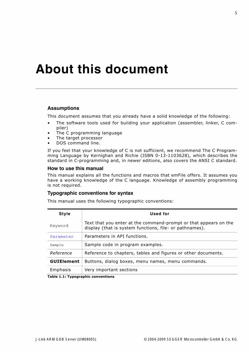
Typographic conventions for syntax
This manual uses the following typographic conventions:
Style Used for
KeywordText that you enter at the command-prompt or that appears on the display (that is system functions, file- or pathnames).
Parameter Parameters in API functions.
Sample Sample code in program examples.
Reference Reference to chapters, tables and figures or other documents.
GUIElement Buttons, dialog boxes, menu names, menu commands.
Emphasis Very important sections
Table 1.1: Typographic conventions
J-Link ARM GDB Server (UM08005) © 2004-2009 SEGGER Microcontroller GmbH & Co. KG
6
EMBEDDED SOFTWARE(Middleware)
emWinGraphics software and GUIemWin is designed to provide an effi-cient, processor- and display control-ler-independent graphical user interface (GUI) for any application that operates with a graphical display. Starterkits, eval- and trial-versions are available.
embOSReal Time Operating SystemembOS is an RTOS designed to offer the benefits of a complete multitasking system for hard real time applications with minimal resources. The profiling PC tool embOSView is included.
emFileFile systememFile is an embedded file system with FAT12, FAT16 and FAT32 support. emFile has been optimized for mini-mum memory consumption in RAM and ROM while maintaining high speed. Various Device drivers, e.g. for NAND and NOR flashes, SD/MMC and Com-pactFlash cards, are available.
emUSBUSB device stackA USB stack designed to work on any embedded system with a USB client controller. Bulk communication and most standard device classes are sup-ported.
SEGGER TOOLS
Flasher Flash programmerFlash Programming tool primarily for microcon-trollers.
J-LinkJTAG emulator for ARM coresUSB driven JTAG interface for ARM cores.
J-TraceJTAG emulator with traceUSB driven JTAG interface for ARM cores with Trace memory. supporting the ARM ETM (Embed-ded Trace Macrocell).
J-Link / J-Trace Related SoftwareAdd-on software to be used with SEGGER�s indus-try standard JTAG emulator, this includes flash programming software and flash breakpoints.
SEGGER Microcontroller GmbH & Co. KG developsand distributes software development tools and ANSIC software components (middleware) for embeddedsystems in several industries such as telecom, medi-cal technology, consumer electronics, automotiveindustry and industrial automation.
SEGGER�s intention is to cut software development-time for embedded applications by offering compact flexible and easy to use middleware,allowing developers to concentrate on their application.
Our most popular products are emWin, a universal graphic software package for embed-ded applications, and embOS, a small yet efficent real-time kernel. emWin, writtenentirely in ANSI C, can easily be used on any CPU and most any display. It is comple-mented by the available PC tools: Bitmap Converter, Font Converter, Simulator andViewer. embOS supports most 8/16/32-bit CPUs. Its small memory footprint makes itsuitable for single-chip applications.
Apart from its main focus on software tools, SEGGER developes and produces program-ming tools for flash microcontrollers, as well as J-Link, a JTAG emulator to assist in devel-opment, debugging and production, which has rapidly become the industry standard fordebug access to ARM cores.
Corporate Office:http://www.segger.com
United States Office:http://www.segger-us.com
J-Link ARM GDB Server (UM08005) © 2004-2009 SEGGER Microcontroller GmbH & Co. KG
7
Table of Contents
1 Introduction ......................................................................................................................9
1.1 GDB / GDB Server overview......................................................................101.2 Hardware requirements ............................................................................101.3 Setup.....................................................................................................10
2 Licensing........................................................................................................................11
2.1 Introduction............................................................................................122.2 License types ..........................................................................................122.2.1 Built-in license ........................................................................................122.2.2 Key-based license....................................................................................132.2.3 �Free evaluation and non commercial use� license........................................13
3 Debugging with GDB .....................................................................................................15
3.1 Starting the J-Link GDB Server..................................................................163.1.1 User interface .........................................................................................163.2 Setting up the J-Link GDB Server...............................................................173.3 Setting up GDB .......................................................................................183.3.1 General GDB startup sequence ..................................................................183.3.2 The .gdbinit file .......................................................................................183.3.3 Running GDB ..........................................................................................193.4 Debugging on Cortex-M3 devices...............................................................203.4.1 Debugging in RAM ...................................................................................203.4.2 Debugging in flash...................................................................................203.5 Supported remote commands....................................................................223.5.1 AllowSimulation.......................................................................................233.5.2 clrbp......................................................................................................233.5.3 cp15 ......................................................................................................233.5.4 endian ...................................................................................................233.5.5 flash breakpoints .....................................................................................243.5.6 flash device ............................................................................................243.5.7 flash download ........................................................................................243.5.8 go .........................................................................................................243.5.9 halt .......................................................................................................243.5.10 jtagconf .................................................................................................253.5.11 long.......................................................................................................253.5.12 memU8..................................................................................................253.5.13 memU16 ................................................................................................263.5.14 memU32 ................................................................................................263.5.15 reg ........................................................................................................263.5.16 remoteport .............................................................................................263.5.17 reset......................................................................................................283.5.18 select.....................................................................................................303.5.19 semihosting enable ..................................................................................303.5.20 semihosting ARMSWI ...............................................................................303.5.21 semihosting ThumbSWI............................................................................303.5.22 setbp .....................................................................................................303.5.23 sleep .....................................................................................................313.5.24 speed.....................................................................................................323.5.25 step.......................................................................................................323.5.26 waithalt..................................................................................................32
J-Link ARM GDB Server (UM08005) © 2004-2009 SEGGER Microcontroller GmbH & Co. KG
8
3.5.27 wice ...................................................................................................... 333.6 Command line options ............................................................................. 343.6.1 -xc ........................................................................................................ 343.6.2 -x ......................................................................................................... 343.6.3 -port ..................................................................................................... 343.7 Running GDB extensions (Insight, Eclipse, etc.) .......................................... 353.7.1 Insight................................................................................................... 363.7.2 Eclipse................................................................................................... 403.7.3 Yagarto.................................................................................................. 40
4 Flash download and Flash breakpoints .........................................................................41
4.1 Licensing................................................................................................ 424.2 Enabeling flash download and flash breakpoints .......................................... 424.2.1 How to use the sample projects ................................................................ 42
5 Using DIGI evalboards...................................................................................................45
5.1 Initial Steps............................................................................................ 465.1.1 Copying .gdbinit files ............................................................................... 465.2 Compiling the board support package (BSP) ............................................... 475.3 Compiling the sample application .............................................................. 485.4 Setting up the GDB configuration file ......................................................... 485.5 Debugging the sample application ............................................................. 49
6 Support ..........................................................................................................................51
6.1 Troubleshooting ...................................................................................... 526.1.1 General procedure................................................................................... 526.1.2 Typical problem scenarios ........................................................................ 526.2 Contacting support .................................................................................. 536.3 FAQ....................................................................................................... 53
7 Glossary.........................................................................................................................55
8 Literature and references...............................................................................................57
J-Link ARM GDB Server (UM08005) © 2004-2009 SEGGER Microcontroller GmbH & Co. KG
9
Chapter 1
Introduction
This chapter gives a short overview about how to start debugging your hardware withthe GDB and the J-Link GDB Server.
J-Link ARM GDB Server (UM08005) © 2004-2009 SEGGER Microcontroller GmbH & Co. KG
10 Introduction
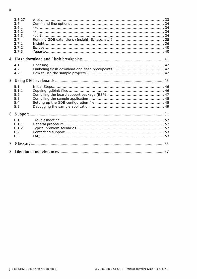
1.1 GDB / GDB Server overviewThe GNU Project Debugger (GDB) is a freely available debugger, distributed underthe terms of the GPL. It connects to an emulator via a TCP/IP connection. It can con-nect to every emulator for which a GDB Server software is available. The latest Unixversion of the GDB is freely available from the GNU commitee under:http://www.gnu.org/software/gdb/download/
GDB Server is a remote server for GDB. When you run GDB in the GDB source direc-tory, it will read a .gdbinit file. The GDB .gdbinit file contains default settinginformations and additional monitor commands. GDB and GDB Server communicatevia a TCP/IP connection, using the standard GDB remote serial protocol. The GDBServer translates the GDB monitor commands into J-Link commands.
1.2 Hardware requirementsTo use J-Link GDB Server, you have to meet the following hardware requirements:
� PC running Win2K / XP / Vista� USB port� J-Link / J-Trace
1.3 SetupThe J-Link setup procedure required in order to work with the J-Link GDB Server isdescribed in chapter 2 of the J-Link User�s Guide. The J-Link User�s Guide is part ofthe J-Link software package which is available for download under www.segger.com.
Host (PC)
USB
JTAG
ARM
J-Link
GDB Server
TCP/IP
GDB compatibleDebugger .gdbinit
+
J-Link ARM GDB Server (UM08005) © 2004-2009 SEGGER Microcontroller GmbH & Co. KG
11
Chapter 2
Licensing
This chapter describes the license management of the software.
J-Link ARM GDB Server (UM08005) © 2004-2009 SEGGER Microcontroller GmbH & Co. KG

12 Licensing
2.1 IntroductionJ-Link GDB Server is distributed as "free for evaluation and non commercial use".
The software can be used free of charge for educational and nonprofit purposes with-out additional license. Without additional license, only 32 KBytes may be down-loaded. To download bigger programs or to use the software for other, especiallycommercial purposes, a license is required. With such a license, the download size isnot limited.
Free evaluation licenses are available upon request. To obtain an trial or unlimitedlicense, please contact [email protected].
Full and valid license terms are specified in file License.txt which comes with the J-Link software and documentation package.
SAM-ICE
J-Link GDB Server can be used free of charge without limitation of program size withSAM-ICE.
2.2 License typesFor the J-Link GDB Server, three types of licenses are available, which will beexplained in the following:
Built-in License
This type of license is easiest to use. The customer does not need to deal with alicense key. The software automatically finds out that the connected J-Link containsthe built-in license(s). This is the type of license you get if you order J-Link and thelicense at the same time, typically in a bundle. Atmel�s SAM-ICE comes with a Built-inlicense for J-Link GDB Server.
Key-based license
This type of license is used if you already have a J-Link, but want to enhance its func-tionality by using J-Link GDB Server. In addition to that, the key-based license isused for trial licenses. To enable this type of license you need to obtain a license keyfrom SEGGER. Free trial licenses are available upon request from www.segger.comThis license key has to be added to the GDB Server license management. How toenter a license key is described in detail in section Entering a license key on page 13.Every license can be used on different PCs, but only with the J-Link the license is for.This means that if you want to use J-Link GDB Server with other J-Links, every J-Linkneeds a license.
“Free evaluation and non commercial use” license
This type of license comes with J-Link GDB Server and is a license for educationaland nonprofit use of J-Link GDB Server. To use this license simply select Start infree mode when the license dialog is opened. In this �free mode� the maximum pro-gram size that can be downloaded with J-Link GDB Server is limited to 32 KBytes.
2.2.1 Built-in licenseThis type of license is easiest to use. The customer does not need to deal with alicense key. The software automatically finds out that the connected J-Link containsthe built-in license(s). To check what licenses the used J-Link have, simply open theJ-Link commander (JLink.exe). The J-Link commander finds and lists all of the J-Link�s licenses automatically, as can be seen in the screenshot below.
J-Link ARM GDB Server (UM08005) © 2004-2009 SEGGER Microcontroller GmbH & Co. KG
13
2.2.2 Key-based licenseWhen using a key-based license, a license key is required in order to unlock the fullpotential of J-Link GDB Server. License keys can be added via the J-Link GDB Serverlicense management. To open the J-Link GDB Server license management simplyselect Licenses... from the Help menu in the main window. Like the built-in license,the key-based license is only valid for one J-Link, so if another J-Link is used it needsa separate license.
When using J-Link GDB Server and no license is found by the software, it will ask fora license key.
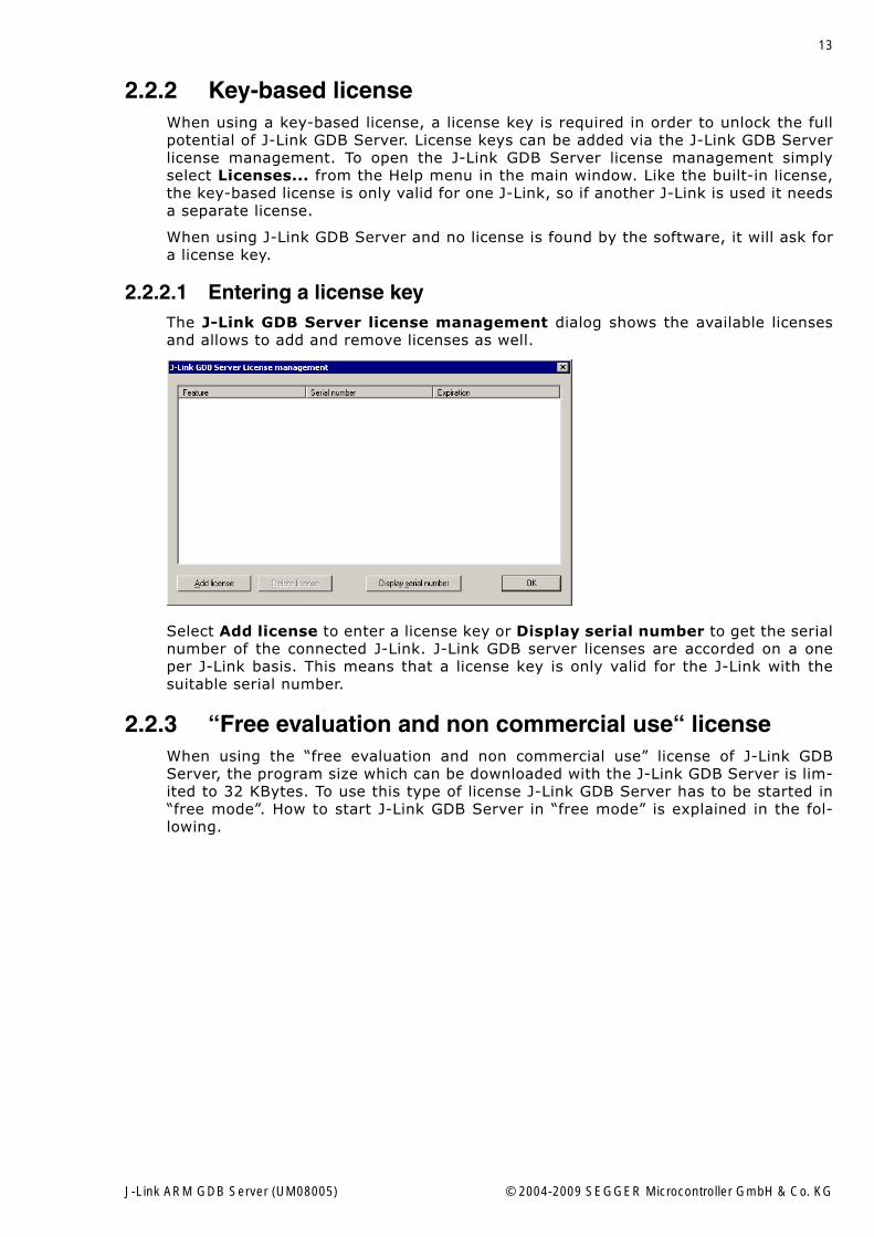
2.2.2.1 Entering a license keyThe J-Link GDB Server license management dialog shows the available licensesand allows to add and remove licenses as well.
Select Add license to enter a license key or Display serial number to get the serialnumber of the connected J-Link. J-Link GDB server licenses are accorded on a oneper J-Link basis. This means that a license key is only valid for the J-Link with thesuitable serial number.
2.2.3 “Free evaluation and non commercial use“ licenseWhen using the �free evaluation and non commercial use� license of J-Link GDBServer, the program size which can be downloaded with the J-Link GDB Server is lim-ited to 32 KBytes. To use this type of license J-Link GDB Server has to be started in�free mode�. How to start J-Link GDB Server in �free mode� is explained in the fol-lowing.
J-Link ARM GDB Server (UM08005) © 2004-2009 SEGGER Microcontroller GmbH & Co. KG
14 Licensing
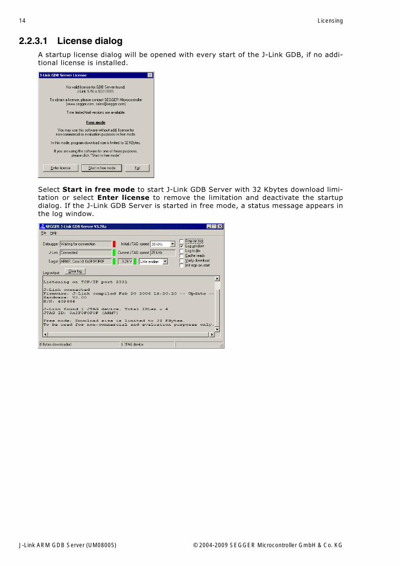
2.2.3.1 License dialogA startup license dialog will be opened with every start of the J-Link GDB, if no addi-tional license is installed.
Select Start in free mode to start J-Link GDB Server with 32 Kbytes download limi-tation or select Enter license to remove the limitation and deactivate the startupdialog. If the J-Link GDB Server is started in free mode, a status message appears inthe log window.
J-Link ARM GDB Server (UM08005) © 2004-2009 SEGGER Microcontroller GmbH & Co. KG
15
Chapter 3
Debugging with GDB
This chapter describes the setup procedure required in order to use the GDB with theJ-Link GDB Server.
J-Link ARM GDB Server (UM08005) © 2004-2009 SEGGER Microcontroller GmbH & Co. KG
16 Debugging with GDB
3.1 Starting the J-Link GDB ServerStart the J-Link GDB Server by double-clicking the executable file. Connect a J-Linkto the host system, as described in chapter Installing the USB driver on page 10.
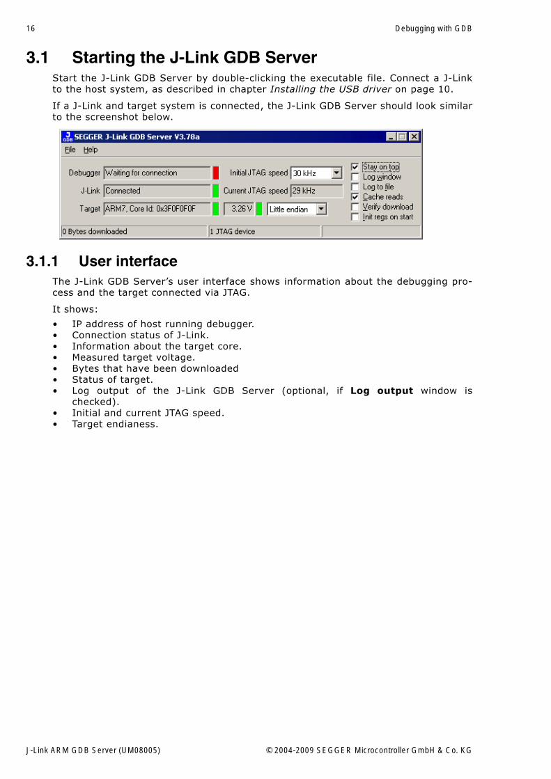
If a J-Link and target system is connected, the J-Link GDB Server should look similarto the screenshot below.
3.1.1 User interfaceThe J-Link GDB Server�s user interface shows information about the debugging pro-cess and the target connected via JTAG.
It shows:
� IP address of host running debugger.� Connection status of J-Link.� Information about the target core.� Measured target voltage.� Bytes that have been downloaded� Status of target.� Log output of the J-Link GDB Server (optional, if Log output window is
checked).� Initial and current JTAG speed.� Target endianess.
J-Link ARM GDB Server (UM08005) © 2004-2009 SEGGER Microcontroller GmbH & Co. KG
17
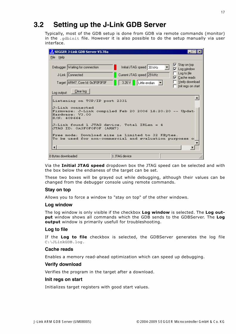
3.2 Setting up the J-Link GDB ServerTypically, most of the GDB setup is done from GDB via remote commands (monitor)in the .gdbinit file. However it is also possible to do the setup manually via userinterface.
Via the Initial JTAG speed dropdown box the JTAG speed can be selected and withthe box below the endianess of the target can be set.
These two boxes will be grayed out while debugging, although their values can bechanged from the debugger console using remote commands.
Stay on top
Allows you to force a window to "stay on top" of the other windows.
Log window
The log window is only visible if the checkbox Log window is selected. The Log out-put window shows all commands which the GDB sends to the GDBServer. The Logoutput window is primarily usefull for troubleshooting.
Log to file
If the Log to file checkbox is selected, the GDBServer generates the log fileC:\JLinkGDB.log.
Cache reads
Enables a memory read-ahead optimization which can speed up debugging.
Verify download
Verifies the program in the target after a download.
Init regs on start
Initializes target registers with good start values.
J-Link ARM GDB Server (UM08005) © 2004-2009 SEGGER Microcontroller GmbH & Co. KG
18 Debugging with GDB
3.3 Setting up GDBWe assume that you already have a solid knowledge of the software toolsused for building your application (assembler, linker, C compiler) and espe-cially the debugger and the debugger frontend of your choice. We do notanswer questions about how to install and use the choosen toolchain.
3.3.1 General GDB startup sequence1. Sets up the command interpreter as specified by the command line.2. Reads the init file (if any) in your home directory and executes all the commands
in that file.3. Processes command line options and operands.4. Reads and executes the commands from init file (if any) in the current working
directory. This is only done if the current directory is different from your homedirectory.
5. Reads command files specified by the -x option.6. Reads the command history recorded in the history file.
For more details about the GDB startup sequence refer to http://www.gnu.org/software/gdb/documentation/.
3.3.2 The .gdbinit fileWhen you run the GDB an initialization file, called .gbdinit, is searched in the GDBhome directory. If the GDB finds a .gdbinit file, GDB executes all the commands inthat file.
It is a good approach to store the setup informations for the remote debugging ses-sion in the .gdbinit file. Some sample files are supplied in the GDBInit folder of theGDB Server installation directory. Choose the sample that best fits to your targetboard, customize it and copy it into your GDB source directory.
You can use the .gdbinit_template as base for the implementation of new hard-ware.
## J-LINK GDB SERVER initialization## This connects to a GDB Server listening# for commands on localhost at tcp port 2331target remote localhost:2331# Set JTAG speed to 30 kHzmonitor speed 30# Set GDBServer to big endianmonitor endian big# Reset the chip to get to a known state.monitor reset
## CPU core initialization (to be done by user)#
# Set the processor modemonitor reg cpsr = 0xd3# Set auto JTAG speedmonitor speed auto# Setup GDB FOR FASTER DOWNLOADSset remote memory-write-packet-size 1024set remote memory-write-packet-size fixed# Load the program executable called "image.elf"# load image.elf
J-Link ARM GDB Server (UM08005) © 2004-2009 SEGGER Microcontroller GmbH & Co. KG
19
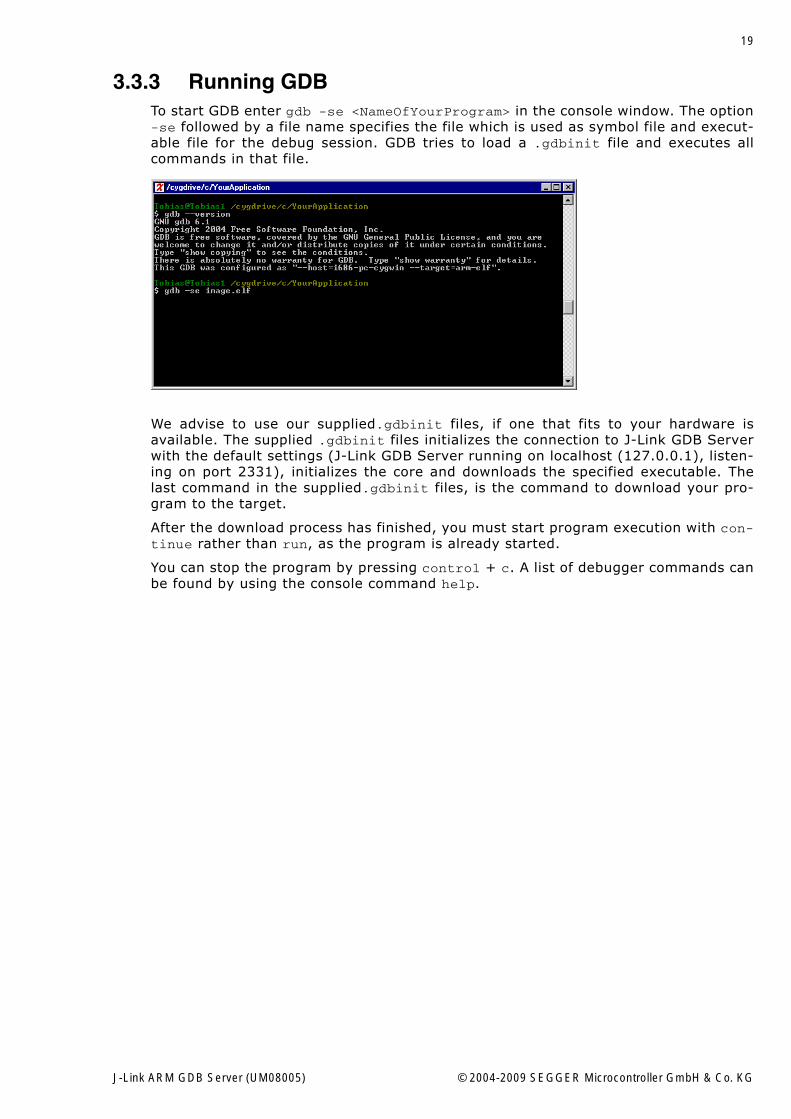
3.3.3 Running GDBTo start GDB enter gdb -se <NameOfYourProgram> in the console window. The option-se followed by a file name specifies the file which is used as symbol file and execut-able file for the debug session. GDB tries to load a .gdbinit file and executes allcommands in that file.
We advise to use our supplied.gdbinit files, if one that fits to your hardware isavailable. The supplied .gdbinit files initializes the connection to J-Link GDB Serverwith the default settings (J-Link GDB Server running on localhost (127.0.0.1), listen-ing on port 2331), initializes the core and downloads the specified executable. Thelast command in the supplied.gdbinit files, is the command to download your pro-gram to the target.
After the download process has finished, you must start program execution with con-tinue rather than run, as the program is already started.
You can stop the program by pressing control + c. A list of debugger commands canbe found by using the console command help.
J-Link ARM GDB Server (UM08005) © 2004-2009 SEGGER Microcontroller GmbH & Co. KG
20 Debugging with GDB
3.4 Debugging on Cortex-M3 devicesJ-Link GDB Server supports debugging on Cortex-M3 devices. Both, debugging inRAM and flash are supported.Flash download (FlashDL) and flash breakpoints (FlashBP) are also available butrequire a separate license.
3.4.1 Debugging in RAMWhen debugging in RAM on a Cortex-M3 device, the stack pointer (SP, R13) and pro-gram counter (PC, R15) are not automatically set to the start values by most debug-gers.In order to debug an application in RAM, please ensure that PC and SP have correctvalues before you start to debug the application.Typically, the start of the vector is the start of the RAM area used for download. Onmost devices, this is 0x20000000. This means that the initial value of the stackpointer (SP) can be read from 0x20000000 and the initial value of the PC can be readfrom 0x20000004.To ensure that the stack pointer and the PC are initialized correctly you can set themin the .gdbinit file as shown below.
Sample GDB init sequence
The following sample GDB init sequence should work on any Cortex-M3 device whendebugging in RAM:
#*************************************************## Connect to J-Link and debug application in flash on Cortex-M3## Download to flash is performed.## Connect to the J-Link gdb servertarget remote localhost:2331monitor speed 1000load ST_MB525_RAM.elf# Initializing PC and stack pointer# RAM_START_ADDR is at 0x20000000monitor reg r13 = (0x20000000)monitor reg pc = (0x20000004)
3.4.2 Debugging in flashWhen debugging in flash the stack pointer and the PC are set automatically when thetarget is reset after the flash download.
Without reset after download, the stack pointer and the PC need to be nitialized cor-rectly, typically in the .gdbinit file. The following sample GDB init sequence is for aSTM32.
Sample GDB init sequence
#*************************************************## Connect to J-Link and debug application in flash on Cortex-M3## no download is performed.## Connect to the J-Link gdb servertarget remote localhost:2331monitor speed 1000# Can not load into flash if device is not specified. load ST_MB525_FLASH.elf# Initializing PC and stack pointermonitor reg r13 = (0x00000000)monitor reg pc = (0x00000004)
J-Link ARM GDB Server (UM08005) © 2004-2009 SEGGER Microcontroller GmbH & Co. KG
21
3.4.2.1 Download to flashTo enable download to flash, the device needs to be selected and flash download hasto be enabled; the license for download (FlashDL) is also required. For more informa-tion, please refer to Enabeling flash download and flash breakpoints on page 42
Sample GDB init sequence
#*************************************************## Connect to J-Link and debug application in flash on Cortex-M3## Download to flash is performed.## Connect to the J-Link gdb servertarget remote localhost:2331monitor speed 1000monitor flash device = STM32F103VBmonitor flash download = 1load ST_MB525_FLASH.elf# Initializing PC and stack pointermonitor reg r13 = (0x00000000)monitor reg pc = (0x00000004)
3.4.2.2 Flash breakpointsMost Cortex-M3 devices offer 6 hardware breakpoints. Can be very conveniant fordebugging to have more than 6 breakpoints. Flash breakpoints are supported formost popular Cortex-M3 devices.To enable flash breakpoints, the device needs to be selected and flash breakpointshave to be enabled; the license for download (FlashBP) is also required. For moreinformation, please refer to Enabeling flash download and flash breakpoints onpage 42.
#*************************************************## Connect to J-Link and debug application in flash on Cortex-M3## Download to flash is performed.## Connect to the J-Link gdb servertarget remote localhost:2331monitor speed 1000monitor flash device = STM32F103VBmonitor flash breakpoints = 1monitor flash download = 1load ST_MB525_FLASH.elf# Initializing PC and stack pointermonitor reg r13 = (0x00000000)monitor reg pc = (0x00000004)
J-Link ARM GDB Server (UM08005) © 2004-2009 SEGGER Microcontroller GmbH & Co. KG
22 Debugging with GDB
3.5 Supported remote commandsJ-Link GDB Server supports several remote commands from the GDB. This commandscan be used from within a .gdbinit file or the GDB console to initialize the targetboard and to setup J-Link GDB Server specific parameters.
GDB sends the remote commands to the GDB Server. Remote command are what fol-lows the GDB command monitor on the same line. If for example you want to startthe target CPU, you have to either enter monitor go in the GDB console window orinclude this line in the .gdbinit file.
Remote command Explanation
AllowSimulation Enables/Disables ARM instruction set simulation.clrbp Removes an instruction breakpoint.cp15 Reads or writes from/to cp15 register.endian Sets endianess of the target.go Starts the target CPU.flash breakpoints Enables/Disables flash breakpoints.flash device Selects the target�s flash device.flash download Enables/Disables flash download.halt Halts the target CPU.jtagconf Configures a JTAG scan chain with multiple devices on it.long Reads or writes a word from/to given address.memU8 Reads or writes a byte from/to given address.memU16 Reads or writes a halfword from/to given address.memU32 Reads or writes a word from/to given address.reg Reads or writes from/to given register.remoteport Changes the GDB server remote port.reset Resets and halts the target CPU.select Selects the way J-Link is connected to host system.semihosting enable Enables semi-hosting.semihosting ARMSWI Sets the SWI number used for semi-hosting in ARM mode.semihostingThumbSWI
Sets the SWI number used for semi-hosting in thumb mode.
setbp Sets an instruction breakpoint at a given address.sleep Sleeps for a given time period.speed Sets the JTAG speed of J-Link / J-Trace.step Performs one or more single instruction steps.waithalt Waits for target to halt code execution.wice Writes to given IceBreaker register.
Table 3.1: GDB remote commands
J-Link ARM GDB Server (UM08005) © 2004-2009 SEGGER Microcontroller GmbH & Co. KG
23
3.5.1 AllowSimulationSyntaxAllowSimulation <Value>
Description
Enables or disables ARM instruction set simulation.
Example
monitor AllowSimulation 1 // Enables ARM instruction set simulationmonitor AllowSimulation 0 // Disables ARM instruction set simulation
3.5.2 clrbpSyntaxClrBP [<BPHandle>]
or
ci [<BPHandle>]
Description
Removes an instruction breakpoint, where <BPHandle> is the handle of breakpoint tobe removed. If no handle is specified this command removes all pending breakpoints.
Example
monitor clrbp 1
or
monitor ci 1
3.5.3 cp15Syntax
cp15 <CRn>, <CRm>, <op1>, <op2> [= <data>]
Description
Reads or writes from/to cp15 register. If <data> is specified, this command writes thedata to the cp15 register. Otherwise this command reads from the cp15 register. Forfurther information please refer to the ARM reference manual.
Example
Read: monitor cp15 1, 2, 6, 7 // ReadWrite: monitor cp15 1, 2, 6, 7 = 0xFFFFFFFF // Write
3.5.4 endianSyntax
endian <endianess>
Description
Sets endianess of target, where <endian> can either be big or little. Example
monitor endian little
Additional information
By default, the GDB server is configured to use big endianess.
J-Link ARM GDB Server (UM08005) © 2004-2009 SEGGER Microcontroller GmbH & Co. KG
24 Debugging with GDB
3.5.5 flash breakpointsSyntax
monitor flash breakpoints = <Value>
Description
This command enables/disables the flash breakpoints feature.
Example
monitor flash breakpoints = 1 // Enable flash breakpointsmonitor flash breakpoints = 0 // Disable flash breakpoints
3.5.6 flash deviceSyntax
flash device = <DeviceID>
Description
Selects the target�s flash device. The flash device is selected by it�s device identifier.For more information about the supported device identifiers, please refer to the J-Link / J-Trace User Guide chapter Flash programming and flash breakpoints.
Example
monitor flash device = AT91SAM7S256
3.5.7 flash downloadSyntax
monitor flash download = <Value>
Description
This command enables/disables the flash download feature.
Example
monitor flash download = 1 // Enables flash downloadmonitor flash download = 0 // Disables flahs download
3.5.8 goSyntax
go
Description
Starts the target CPU.
Example
monitor go
3.5.9 haltSyntax
halt
Description
Halts the target CPU.
J-Link ARM GDB Server (UM08005) © 2004-2009 SEGGER Microcontroller GmbH & Co. KG
25
Example
monitor halt
3.5.10 jtagconfSyntax
jtagconf <IRPre> <DRPre>
Description
Configures a JTAG scan chain with multiple devices on it. <IRPre> is the sum ofIRLens of all devices closer to TDI, where IRLen is the number of bits in the IR(Instruction Register) of one device. <DRPre> is the number of devices closer to TDI.For more detailed information of how to configure a scan chain with multiple devicesplease refer to the J-Link ARM User�s Guide.
Example
monitor jtagconf 4 1
3.5.11 longSyntax
long <address> [= <value>]
Description
Reads or writes from/to given address. If <value> is specified, this command writesthe value to the given address. Otherwise this command reads from the givenaddress. This command is similiar to the WriteU32 command. Refer to memU32 onpage 26 for more information.
Example
monitor long 0x50000000 // Readmonitor long 0x50000000 = 0xFFFF // Write
3.5.12 memU8Syntax
MemU8 <address> [= <value>]
Description
Reads or writes a byte from/to a given address. If <value> is specified, this com-mand writes the value to the given address. Otherwise this command reads from thegiven address.
Example
monitor memU8 0x50000000 // Readmonitor memU8 0x50000000 = 0xFF // Write
J-Link ARM GDB Server (UM08005) © 2004-2009 SEGGER Microcontroller GmbH & Co. KG
26 Debugging with GDB
3.5.13 memU16Syntax
memU16 <address> [= <value>]
Description
Reads or writes a halfword from/to a given address. If <value> is specified, this com-mand writes the value to the given address. Otherwise this command reads from thegiven address.
Example
monitor memU16 0x50000000 // Readmonitor memU16 0x50000000 = 0xFFFF // Write
3.5.14 memU32Syntax
MemU32 <address> [= <value>]
Description
Reads or writes a word from/to a given address. If <value> is specified, this com-mand writes the value to the given address. Otherwise this command reads from thegiven address. This command is similar to the long command. Refer to long onpage 25 for more information.
Example
monitor MemU32 0x50000000 // Readmonitor MemU32 0x50000000 = 0xFFFFFFFF // Write
3.5.15 regSyntax
reg <RegName> [= <value>]
or
reg <RegName> [= (<address>)]
Description
Reads or writes from/to given register. If <value> is specified, this command writesthe value into the given register. If <address> is specified, this command writes thememory content at address <address> to register <RegName>. Otherwise this com-mand reads the given register.
Example
monitor reg pc = 0x00monitor reg cpsr = 0x1Fmonitor reg r0 = (0x40)monitor reg pc = (0x100)
3.5.16 remoteportSyntax
remoteport <port>
Description
Changes the port an which the GDB server listens for connections.
J-Link ARM GDB Server (UM08005) © 2004-2009 SEGGER Microcontroller GmbH & Co. KG
27
Example
monitor remoteport 8000
J-Link ARM GDB Server (UM08005) © 2004-2009 SEGGER Microcontroller GmbH & Co. KG
28 Debugging with GDB
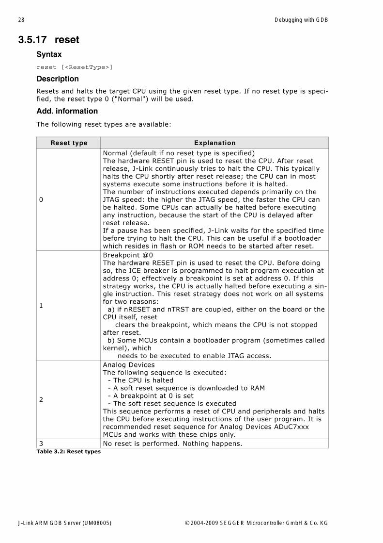
3.5.17 resetSyntax
reset [<ResetType>]
Description
Resets and halts the target CPU using the given reset type. If no reset type is speci-fied, the reset type 0 ("Normal") will be used.
Add. information
The following reset types are available:
Reset type Explanation
0
Normal (default if no reset type is specified)The hardware RESET pin is used to reset the CPU. After reset release, J-Link continuously tries to halt the CPU. This typically halts the CPU shortly after reset release; the CPU can in most systems execute some instructions before it is halted.The number of instructions executed depends primarily on the JTAG speed: the higher the JTAG speed, the faster the CPU can be halted. Some CPUs can actually be halted before executing any instruction, because the start of the CPU is delayed after reset release.If a pause has been specified, J-Link waits for the specified time before trying to halt the CPU. This can be useful if a bootloader which resides in flash or ROM needs to be started after reset.
1
Breakpoint @0The hardware RESET pin is used to reset the CPU. Before doing so, the ICE breaker is programmed to halt program execution at address 0; effectively a breakpoint is set at address 0. If this strategy works, the CPU is actually halted before executing a sin-gle instruction. This reset strategy does not work on all systems for two reasons: a) if nRESET and nTRST are coupled, either on the board or the CPU itself, reset clears the breakpoint, which means the CPU is not stopped after reset. b) Some MCUs contain a bootloader program (sometimes called kernel), which needs to be executed to enable JTAG access.
2
Analog DevicesThe following sequence is executed: - The CPU is halted - A soft reset sequence is downloaded to RAM - A breakpoint at 0 is set - The soft reset sequence is executedThis sequence performs a reset of CPU and peripherals and halts the CPU before executing instructions of the user program. It is recommended reset sequence for Analog Devices ADuC7xxx MCUs and works with these chips only.
3 No reset is performed. Nothing happens.Table 3.2: Reset types
J-Link ARM GDB Server (UM08005) © 2004-2009 SEGGER Microcontroller GmbH & Co. KG
29
Example
monitor resetmonitor reset 1
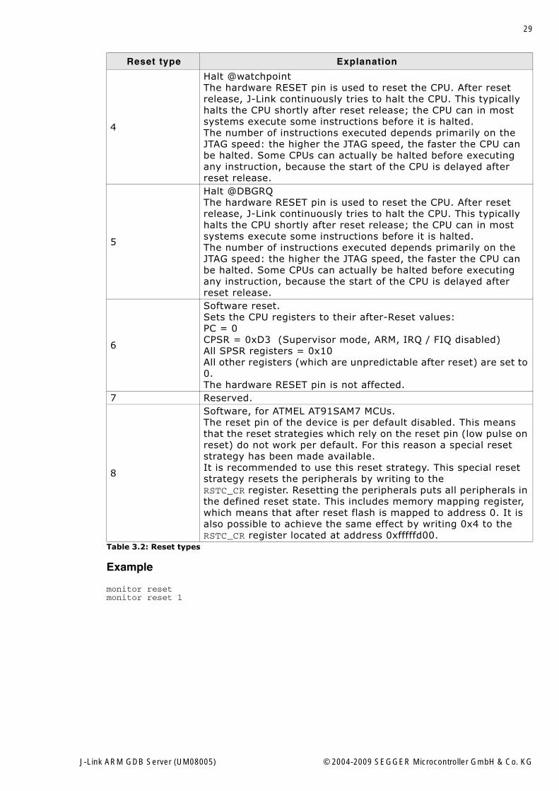
4
Halt @watchpointThe hardware RESET pin is used to reset the CPU. After reset release, J-Link continuously tries to halt the CPU. This typically halts the CPU shortly after reset release; the CPU can in most systems execute some instructions before it is halted.The number of instructions executed depends primarily on the JTAG speed: the higher the JTAG speed, the faster the CPU can be halted. Some CPUs can actually be halted before executing any instruction, because the start of the CPU is delayed after reset release.
5
Halt @DBGRQThe hardware RESET pin is used to reset the CPU. After reset release, J-Link continuously tries to halt the CPU. This typically halts the CPU shortly after reset release; the CPU can in most systems execute some instructions before it is halted.The number of instructions executed depends primarily on the JTAG speed: the higher the JTAG speed, the faster the CPU can be halted. Some CPUs can actually be halted before executing any instruction, because the start of the CPU is delayed after reset release.
6
Software reset.Sets the CPU registers to their after-Reset values:PC = 0CPSR = 0xD3 (Supervisor mode, ARM, IRQ / FIQ disabled)All SPSR registers = 0x10All other registers (which are unpredictable after reset) are set to 0.The hardware RESET pin is not affected.
7 Reserved.
8
Software, for ATMEL AT91SAM7 MCUs.The reset pin of the device is per default disabled. This means that the reset strategies which rely on the reset pin (low pulse on reset) do not work per default. For this reason a special reset strategy has been made available.It is recommended to use this reset strategy. This special reset strategy resets the peripherals by writing to theRSTC_CR register. Resetting the peripherals puts all peripherals in the defined reset state. This includes memory mapping register, which means that after reset flash is mapped to address 0. It is also possible to achieve the same effect by writing 0x4 to the RSTC_CR register located at address 0xfffffd00.
Reset type Explanation
Table 3.2: Reset types
J-Link ARM GDB Server (UM08005) © 2004-2009 SEGGER Microcontroller GmbH & Co. KG
30 Debugging with GDB
3.5.18 selectSyntax
select USB
or
select IP = <hostname>
Description
Selects the way J-Link / J-Trace is connected to the host system.
Example
monitor select USBmonitor select IP = localhost
3.5.19 semihosting enableSyntax
semihosting enable [<VectorAddr>]
Description
Enables semi-hosting with the specified vector address. If no vector address is spec-ified, the SWI vector (at address 0x8) will be used.
Example
monitor semihosting enable
3.5.20 semihosting ARMSWISyntax
semihosting ARMSWI <Value>
Description
Sets the SWI number used for semi-hosting in ARM mode. The default value for theARMSWI is 0x123456.
Example
monitor semihosting ARMSWI 0x123456
3.5.21 semihosting ThumbSWISyntax
semihosting ThumbSWI <Value>
Description
Sets the SWI number used for semi-hosting in thumb mode. The default value for theThumbSWI is 0xAB
Example
monitor semihosting ThumbSWI 0xAB
3.5.22 setbpSyntax
setbp <Addr> [<Mask>]
or
J-Link ARM GDB Server (UM08005) © 2004-2009 SEGGER Microcontroller GmbH & Co. KG
31
bi <Addr> [<Mask>]
Description
Sets an instruction breakpoint at the given address, where <Mask> is the addressmask to be used. If no mask is specified a default mask of 0x03 is used (matches forbreakpoints on ARM instructions). For breakpoints on THUMB instructions a mask of0x01 should be specified.
Example
monitor setbp 0x00monitor setbp 0x100 0x01
3.5.23 sleepSyntax
sleep <Delay>
Description
Sleeps for a given time, where <Delay> is the time pediod in milliseconds to delay.
Example
monitor sleep 1000
J-Link ARM GDB Server (UM08005) © 2004-2009 SEGGER Microcontroller GmbH & Co. KG
32 Debugging with GDB
3.5.24 speedSyntax
speed <kHz>|auto|adaptive
Description
Sets the JTAG speed of J-Link / J-Trace. Speed can be either fixed (in kHz), automaticrecognition or adaptive. In general, Adaptive is recommended if the target has anRTCK signal which is connected to the corresponding RTCK pin of the device (S-coresonly). Refer to J-Link / J-Trace User Manual for detailed information about the differ-ent modes.
Example
monitor speed 1000monitor speed automonitor speed adaptive
3.5.25 stepSyntax
step [<NumSteps>]
or
si [<NumSteps>]
Description
Performs one or more single instruction steps, where <NumSteps> is the number ofinstruction steps to perform. If <NumSteps> is not specified only one instruction stepwill be performed.
Example
monitor step 3
3.5.26 waithaltSyntax
waithalt <Timeout>
or
wh <Timeout>
Description
Waits for target to halt code execution, where <Timeout> is the maximum timeperiod in milliseconds to wait.
Example
monitor waithalt 2000
or
monitor wh 2000
J-Link ARM GDB Server (UM08005) © 2004-2009 SEGGER Microcontroller GmbH & Co. KG
33
3.5.27 wiceSyntax
wice <RegIndex> <value>
or
rmib <RegIndex> <value>
Description
Writes to given IceBreaker register, where <value> is the data to write.
Example
monitor wice 0x0C 0x100
or
monitor rmib 0x0C 0x100
J-Link ARM GDB Server (UM08005) © 2004-2009 SEGGER Microcontroller GmbH & Co. KG
34 Debugging with GDB
3.6 Command line optionsYou can use command line configuration options to start the J-Link GDB Server with aconfiguration file or set the listening port of the J-Link GDB Server.
The configuration file can be used as an alternative to the gdbinit file. All commandslisted in Supported remote commands on page 22 can be used.
Sample configuration file
//// J-LINK GDB SERVER Configuration file//// Set the listening port of GDB Server to tcp port 2331port 2331// Set JTAG speed to 30 kHzspeed 30// Set GDBServer to little endianendian little// Reset the chip to get to a known state.reset
3.6.1 -xcDescription
Starts the GDB server with a configuration file. The commands in the configurationfile will not be executed until a debugging session is started. The J-Link GDB Serverexecutes the commands specified in the configuration file with every start of adebugging session.
Example
jlinkgdbserver -xc <YourConfigurationFile>
3.6.2 -xDescription
Starts the J-Link GDB server with a configuration file. In contrast to the -xc com-mand line option runs the J-Link GDB Server the commands in the configuration fileonce only direct after the start of the J-Link GDB Server.
Example
jlinkgdbserver -x <YourConfigurationFile>
3.6.3 -portDescription
Starts the GDB Server listening on a specified port. This option overrides the defaultlistening port of the J-Link GDB Server.
Example
jlinkgdbserver -port
J-Link ARM GDB Server (UM08005) © 2004-2009 SEGGER Microcontroller GmbH & Co. KG
35
3.7 Running GDB extensions (Insight, Eclipse, etc.)There are many extensions and graphical user interfaces for GDB available. The range of products reaches from standalone implementations like GNU Insight(http://sources.redhat.com/insight/), frontends like DataDisplayDebugger (DDD)(http://www.gnu.org/software/ddd/) and IDEs like Eclipse (http://www.eclipse.org).
The J-Link GDB Server is tested with:
GDB version 6.1Insight version 6.1Eclipse version 3.2.0 and CDT version 3.1.0.
We appologize that you are familiar with all tools, which you use for the developmentof your application. The following information should only help to to round out thecontext in which the J-Link GDB Server can be used.
Note: We only support problems directly related to the J-Link GDB Server. Prob-lems and questions related to your remaining toolchain have to be solved on yourown.
J-Link ARM GDB Server (UM08005) © 2004-2009 SEGGER Microcontroller GmbH & Co. KG
36 Debugging with GDB
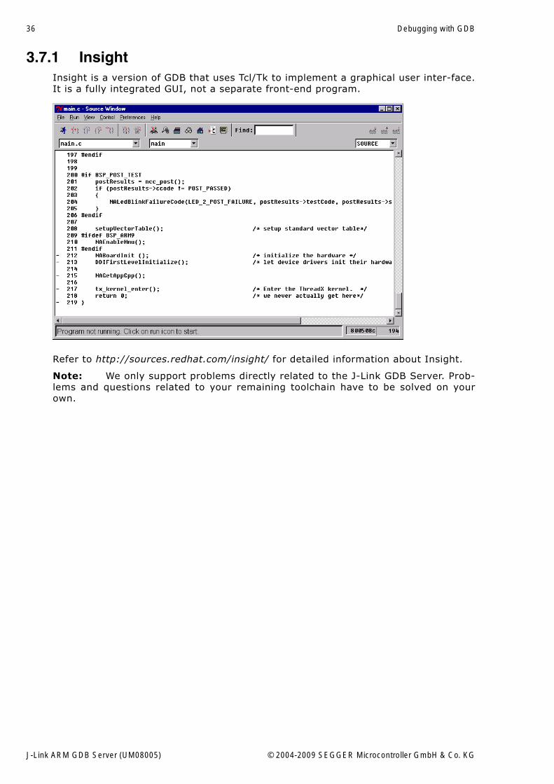
3.7.1 InsightInsight is a version of GDB that uses Tcl/Tk to implement a graphical user inter-face.It is a fully integrated GUI, not a separate front-end program.
Refer to http://sources.redhat.com/insight/ for detailed information about Insight.
Note: We only support problems directly related to the J-Link GDB Server. Prob-lems and questions related to your remaining toolchain have to be solved on yourown.
J-Link ARM GDB Server (UM08005) © 2004-2009 SEGGER Microcontroller GmbH & Co. KG
37
3.7.1.1 Start a debug session with Insight and J-Link GDB Server You can start a debug session with Insight in the following way:
1. Start Insight2. Open your program in Insight.3. Connect to J-Link GDB Server4. Download your program to your target5. Run and debug your program
Start Insight
Enter gdbtk in your console window to start Insight.
Open your program in Insight.
To open your program in Insight, choose File | Open and select the executable thatyou want to debug.
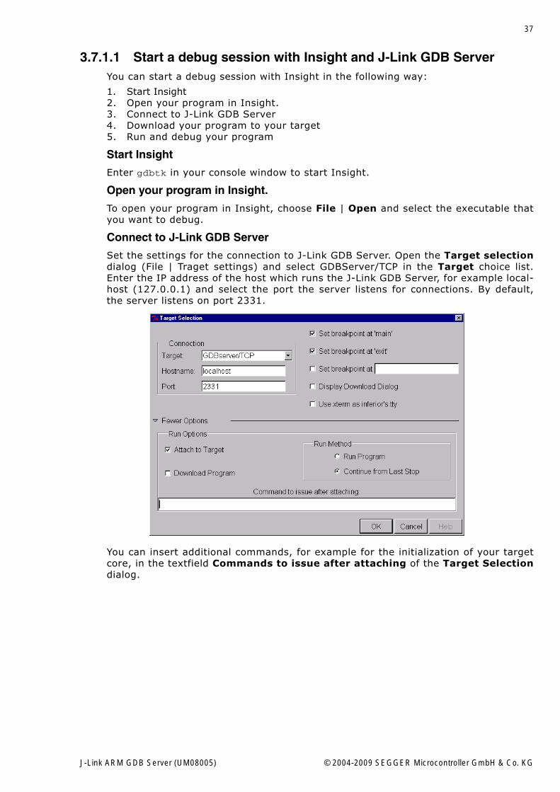
Connect to J-Link GDB Server
Set the settings for the connection to J-Link GDB Server. Open the Target selectiondialog (File | Traget settings) and select GDBServer/TCP in the Target choice list.Enter the IP address of the host which runs the J-Link GDB Server, for example local-host (127.0.0.1) and select the port the server listens for connections. By default,the server listens on port 2331.
You can insert additional commands, for example for the initialization of your targetcore, in the textfield Commands to issue after attaching of the Target Selectiondialog.
J-Link ARM GDB Server (UM08005) © 2004-2009 SEGGER Microcontroller GmbH & Co. KG
38 Debugging with GDB
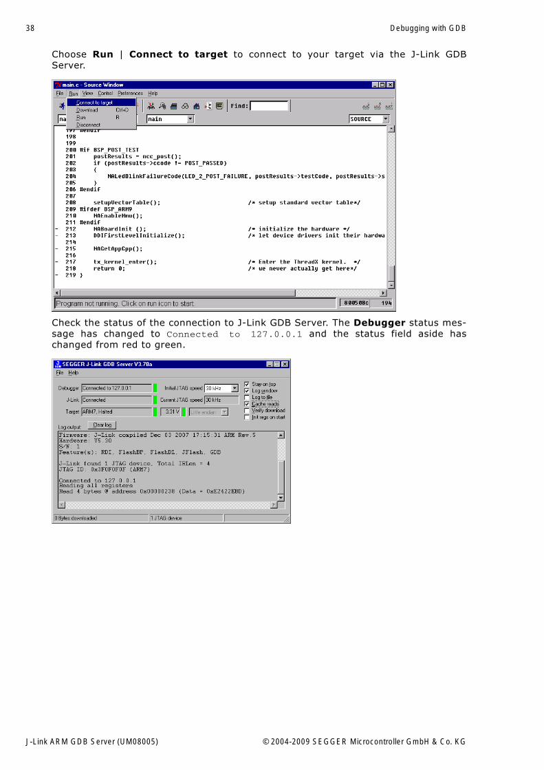
Choose Run | Connect to target to connect to your target via the J-Link GDBServer.
Check the status of the connection to J-Link GDB Server. The Debugger status mes-sage has changed to Connected to 127.0.0.1 and the status field aside haschanged from red to green.
J-Link ARM GDB Server (UM08005) © 2004-2009 SEGGER Microcontroller GmbH & Co. KG
39
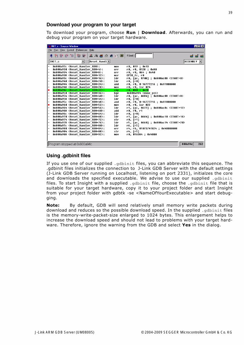
Download your program to your target
To download your program, choose Run | Download. Afterwards, you can run anddebug your program on your target hardware.
Using .gdbinit files
If you use one of our supplied .gdbinit files, you can abbreviate this sequence. The.gdbinit files initializes the connection to J-Link GDB Server with the default settings(J-Link GDB Server running on Localhost, listening on port 2331), initialzes the coreand downloads the specified executable. We advise to use our supplied .gdbinitfiles. To start Insight with a supplied .gdbinit file, choose the .gdbinit file that issuitable for your target hardware, copy it to your project folder and start Insightfrom your project folder with gdbtk -se <NameOfYourExecutable> and start debug-ging.
Note: By default, GDB will send relatively small memory write packets duringdownload and reduces so the possible download speed. In the supplied .gdbinit filesis the memory-write-packet-size enlarged to 1024 bytes. This enlargement helps toincrease the download speed and should not lead to problems with your target hard-ware. Therefore, ignore the warning from the GDB and select Yes in the dialog.
J-Link ARM GDB Server (UM08005) © 2004-2009 SEGGER Microcontroller GmbH & Co. KG
40 Debugging with GDB
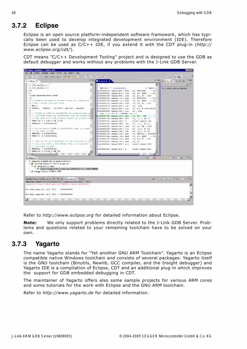
3.7.2 EclipseEclipse is an open source platform-independent software framework, which has typi-cally been used to develop integrated development environment (IDE). ThereforeEclipse can be used as C/C++ IDE, if you extend it with the CDT plug-in (http://www.eclipse.org/cdt/).
CDT means "C/C++ Development Tooling" project and is designed to use the GDB asdefault debugger and works without any problems with the J-Link GDB Server.
Refer to http://www.eclipse.org for detailed information about Eclipse.
Note: We only support problems directly related to the J-Link GDB Server. Prob-lems and questions related to your remaining toolchain have to be solved on yourown.
3.7.3 YagartoThe name Yagarto stands for �Yet another GNU ARM Toolchain�. Yagarto is an Eclipsecompatible native Windows toolchain and consists of several packages. Yagarto itselfis the GNU toolchain (Binutils, Newlib, GCC compiler, and the Insight debugger) andYagarto IDE is a compilation of Eclipse, CDT and an additional plug-in which improvesthe support for GDB embedded debugging in CDT.
The maintainer of Yagarto offers also some sample projects for various ARM coresand some tutorials for the work with Eclipse and the GNU ARM toolchain.
Refer to http://www.yagarto.de for detailed information.
J-Link ARM GDB Server (UM08005) © 2004-2009 SEGGER Microcontroller GmbH & Co. KG
41
Chapter 4
Flash download and Flash break-points
This chapter describes how to use the J-Link flash download and Flash breakpointfeatures with the GDB Server.
J-Link ARM GDB Server (UM08005) © 2004-2009 SEGGER Microcontroller GmbH & Co. KG
42 Flash download and Flash breakpoints
4.1 LicensingFlash download and flash breakpoints are features of the J-Link software whichrequire separat licenses from SEGGER.
4.2 Enabeling flash download and flash breakpointsTo use flash download and flash breakpoints with the J-Link GDB Server you have toenable them first. This is done by the remote commands flash device flash down-load and flash breakpoints. For more information about the flash device commandplease refer to chapter Supported remote commands on page 22. For example, if youwant to enable flash download and flash breakpoints for a Atmel AT91SAM7S256device simply add the following three lines to the .gdbinit file:
monitor flash device = AT91SAM7S256monitor flash download = 1monitor flash breakpoints = 1
The J-Link GDB Server comes with sample projects for the most common flash micro-controllers. The sample projects can be found at Samples\GDB\Projects of theinstallation directory of the J-Link software and documentation package.
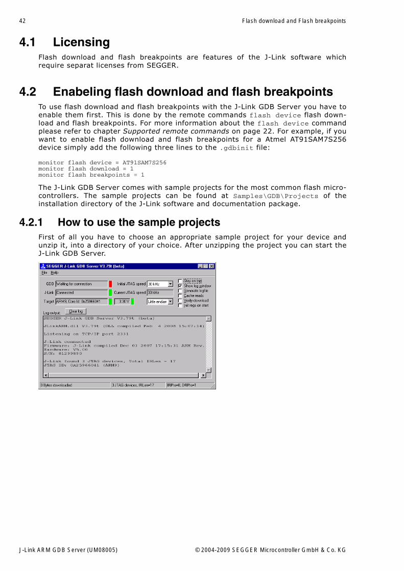
4.2.1 How to use the sample projectsFirst of all you have to choose an appropriate sample project for your device andunzip it, into a directory of your choice. After unzipping the project you can start theJ-Link GDB Server.
J-Link ARM GDB Server (UM08005) © 2004-2009 SEGGER Microcontroller GmbH & Co. KG
43
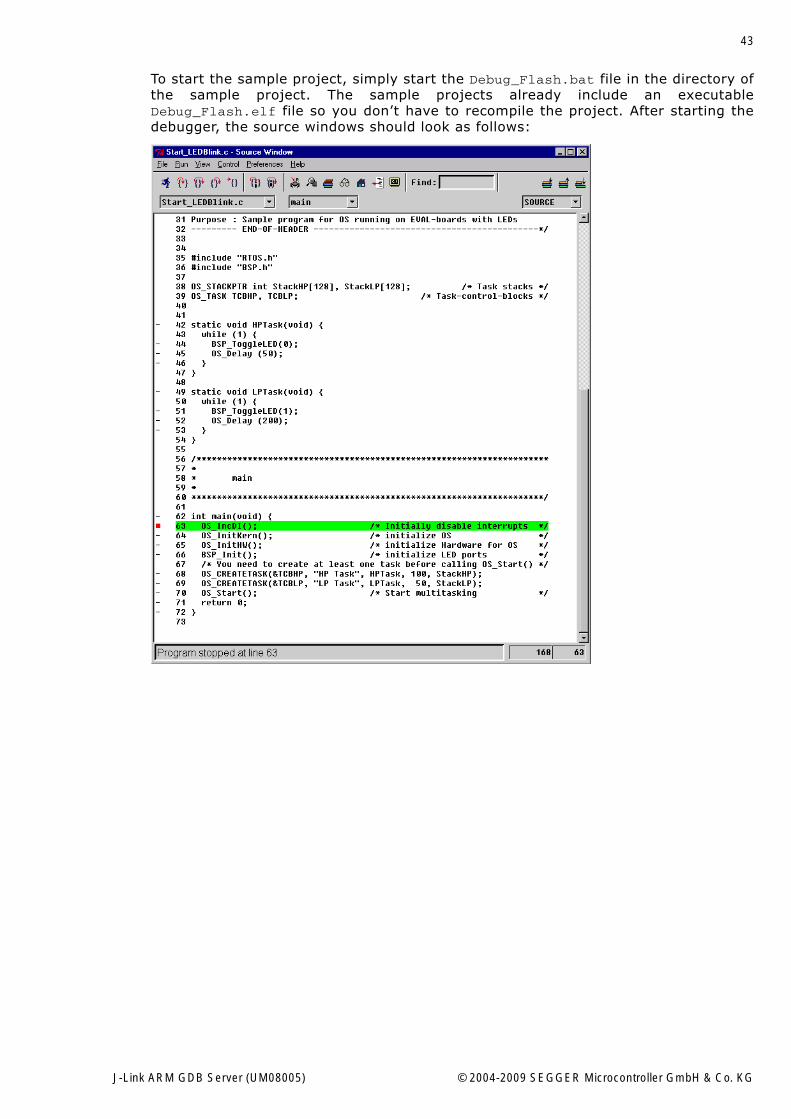
To start the sample project, simply start the Debug_Flash.bat file in the directory ofthe sample project. The sample projects already include an executableDebug_Flash.elf file so you don�t have to recompile the project. After starting thedebugger, the source windows should look as follows:
J-Link ARM GDB Server (UM08005) © 2004-2009 SEGGER Microcontroller GmbH & Co. KG
44 Flash download and Flash breakpoints
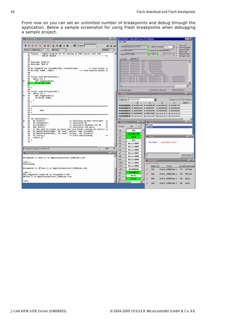
From now on you can set an unlimited number of breakpoints and debug through theapplication. Below a sample screenshot for using Flash breakpoints when debugginga sample project.
J-Link ARM GDB Server (UM08005) © 2004-2009 SEGGER Microcontroller GmbH & Co. KG
45
Chapter 5
Using DIGI evalboards
This chapter describes the setup procedure required in order to debug DIGI boardswith the GDB and the J-Link GDB Server. This includes primarily the compilation rou-tines and configuration hints for the DIGI sample applications. In this case we willrefer to the DIGI Connect ME hardware.
J-Link ARM GDB Server (UM08005) © 2004-2009 SEGGER Microcontroller GmbH & Co. KG
46 Using DIGI evalboards
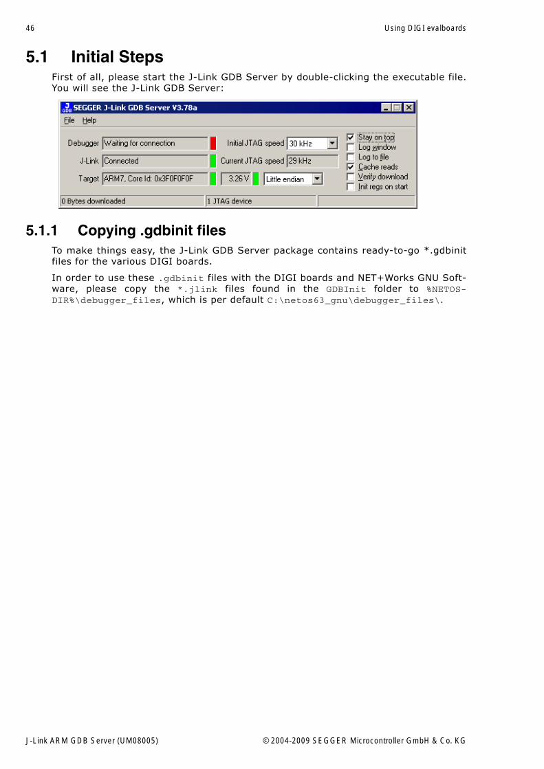
5.1 Initial StepsFirst of all, please start the J-Link GDB Server by double-clicking the executable file.You will see the J-Link GDB Server:
5.1.1 Copying .gdbinit filesTo make things easy, the J-Link GDB Server package contains ready-to-go *.gdbinitfiles for the various DIGI boards.
In order to use these .gdbinit files with the DIGI boards and NET+Works GNU Soft-ware, please copy the *.jlink files found in the GDBInit folder to %NETOS-DIR%\debugger_files, which is per default C:\netos63_gnu\debugger_files\.
J-Link ARM GDB Server (UM08005) © 2004-2009 SEGGER Microcontroller GmbH & Co. KG
47
5.2 Compiling the board support package (BSP)After starting the Net+Works 6.3 Build Environment, you will find yourself in a Unixlike shell environment with a command prompt.
To compile the board support package (BSP), change to the bsp directory, which islocated under /cygdrive/c/netos63_gnu/src/bsp by using the cd command whichstands for "change directory".
cd src/bsp
To list the available BSPs, please use the following command:
ls platforms/ -l
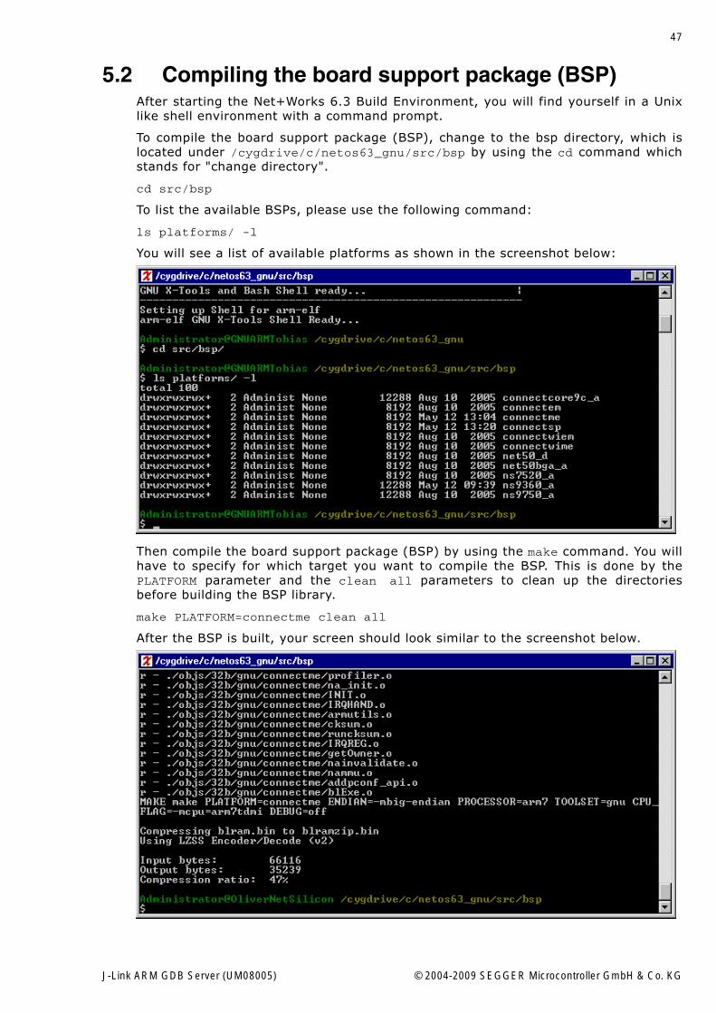
You will see a list of available platforms as shown in the screenshot below:
Then compile the board support package (BSP) by using the make command. You willhave to specify for which target you want to compile the BSP. This is done by thePLATFORM parameter and the clean all parameters to clean up the directoriesbefore building the BSP library.
make PLATFORM=connectme clean all
After the BSP is built, your screen should look similar to the screenshot below.
J-Link ARM GDB Server (UM08005) © 2004-2009 SEGGER Microcontroller GmbH & Co. KG
48 Using DIGI evalboards
Now you can start to compile the sample application, which is described under Com-piling the sample application on page 48.
5.3 Compiling the sample applicationAfter building the BSP for your DIGI board, change to the /cygdrive/c/netos63_gnu/src/apps/template/32b directory by using the following command:
cd /cygdrive/c/netos63_gnu/src/apps/template/32b
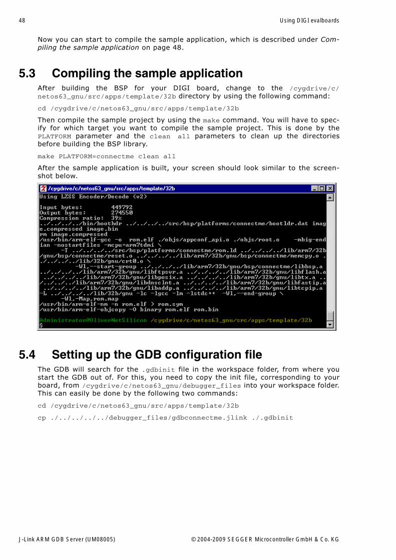
Then compile the sample project by using the make command. You will have to spec-ify for which target you want to compile the sample project. This is done by thePLATFORM parameter and the clean all parameters to clean up the directoriesbefore building the BSP library.
make PLATFORM=connectme clean all
After the sample application is built, your screen should look similar to the screen-shot below.
5.4 Setting up the GDB configuration fileThe GDB will search for the .gdbinit file in the workspace folder, from where youstart the GDB out of. For this, you need to copy the init file, corresponding to yourboard, from /cygdrive/c/netos63_gnu/debugger_files into your workspace folder.This can easily be done by the following two commands:
cd /cygdrive/c/netos63_gnu/src/apps/template/32b
cp ./../../../../debugger_files/gdbconnectme.jlink ./.gdbinit
J-Link ARM GDB Server (UM08005) © 2004-2009 SEGGER Microcontroller GmbH & Co. KG
49
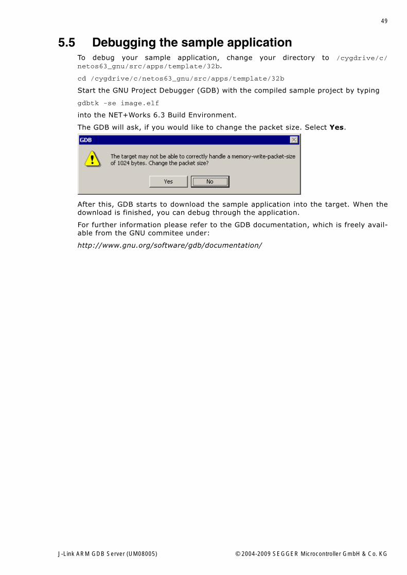
5.5 Debugging the sample applicationTo debug your sample application, change your directory to /cygdrive/c/netos63_gnu/src/apps/template/32b.
cd /cygdrive/c/netos63_gnu/src/apps/template/32b
Start the GNU Project Debugger (GDB) with the compiled sample project by typing
gdbtk -se image.elf
into the NET+Works 6.3 Build Environment.
The GDB will ask, if you would like to change the packet size. Select Yes.
After this, GDB starts to download the sample application into the target. When thedownload is finished, you can debug through the application.
For further information please refer to the GDB documentation, which is freely avail-able from the GNU commitee under:
http://www.gnu.org/software/gdb/documentation/
J-Link ARM GDB Server (UM08005) © 2004-2009 SEGGER Microcontroller GmbH & Co. KG
50 Using DIGI evalboards
J-Link ARM GDB Server (UM08005) © 2004-2009 SEGGER Microcontroller GmbH & Co. KG
51
Chapter 6
Support
This chapter contains troubleshooting tips together with solutions for common prob-lems which might occur when using J-Link / J-Trace. There are several steps you cantake before contacting support. Performing these steps can solve many problems andoften eliminates the need for assistance.
Further instructions are explained in the J-Link / J-Trace User�s Guide.
J-Link ARM GDB Server (UM08005) © 2004-2009 SEGGER Microcontroller GmbH & Co. KG
52 Support
6.1 Troubleshooting
6.1.1 General procedureIf you experience problems with a J-Link / J-Trace, you should follow the steps belowto solve these problems:
1. Close all running applications on your host system.2. Disconnect the J-Link / J-Trace device from USB.3. Power-off target.4. Re-connect J-Link / J-Trace with host system (attach USB cable).5. Power-on target.6. Try your target application again. If the problem vanished, you are done; other-
wise continue.7. Close all running applications on your host system again.8. Disconnect the J-Link / J-Trace device from USB.9. Power-off target.10. Re-connect J-Link / J-Trace with host system (attach USB cable).11. Power-on target.12. Start JLink.exe.13. If JLink.exe reports the J-Link / J-Trace serial number and the target processor�s
core ID, the J-Link / J-Trace is working properly and cannot be the cause of yourproblem.
14. If JLink.exe is unable to read the target processor�s core ID you should analyzethe communication between your target and J-Link / J-Trace with a logic analyzeror oscilloscope. Follow the instructions in section 9.2 in the J-Link / J-Trace User�sGuide.
15. If your problem persists and you own an original product (not an OEM version),see section Contacting support on page 53.
6.1.2 Typical problem scenariosJ-Link / J-Trace LED is off
Meaning:
The USB connection does not work.
Remedy:
Check the USB connection. Try to re-initialize J-Link / J-Trace by disconnecting andreconnecting it. Make sure that the connectors are firmly attached. Check the cableconnections on your J-Link / J-Trace and the computer. If this does not solve theproblem, please check if your cable is defective. If the USB cable is ok, try a differentPC.
J-Link / J-Trace LED is flashing at a high frequency
Meaning:
J-Link / J-Trace could not be enumerated by the USB controller.
Most likely reasons:
a.) Another program is already using J-Link / J-Trace.
b.) The J-Link USB driver does not work correctly.
Remedy:
a.) Close all running applications and try to reinitialize J-Link / J-Trace by disconnect-ing and reconnecting it.
b.) If the LED blinks permanently, check the correct installation of the J-Link USBdriver. Deinstall and reinstall the driver as shown in chapter Setup on page 9.
J-Link ARM GDB Server (UM08005) © 2004-2009 SEGGER Microcontroller GmbH & Co. KG
53
J-Link/J-Trace does not get any connection to the target
Most likely reasons:
a.) The JTAG cable is defective
b.) The target hardware is defective
Remedy:
Please follow the steps described in section 9.1.1 in the J-Link / J-Trace User�s Guide.
6.2 Contacting supportBefore contacting support, make sure you tried to solve your problem by followingthe steps outlined in section �General procedure� in the J-Link / J-Trace User�s Guide.You may also try your J-Link / J-Trace with another PC and if possible with anothertarget system to see if it works there. If the device functions correctly, the USB setupon the original machine or your target hardware is the source of the problem, not J-Link / J-Trace.
If you need to contact support, please send the following information to [email protected]:
� A detailed description of the problem.� J-Link/J-Trace serial number.� Output of JLink.exe if available.� Your findings of the signal analysis.� Information about your target hardware (processor, board etc.).
J-Link / J-Trace is sold directly by SEGGER or as OEM-product by other vendors. Wecan support only official SEGGER products.
6.3 FAQQ: Which CPUs are supported?A: Every CPU supported by J-Link / J-Trace is supported.
J-Link ARM GDB Server (UM08005) © 2004-2009 SEGGER Microcontroller GmbH & Co. KG
54 Support
J-Link ARM GDB Server (UM08005) © 2004-2009 SEGGER Microcontroller GmbH & Co. KG
55
Chapter 7
Glossary
This chapter explains important terms used throughout this manual.
J-Link ARM GDB Server (UM08005) © 2004-2009 SEGGER Microcontroller GmbH & Co. KG
56 Glossary
Big-endian
Memory organization where the least significant byte of a word is at a higher address
than the most significant byte. See Little-endian.
Cache cleaning
The process of writing dirty data in a cache to main memory.
GDB
A GNU Project Debugger that is freely available.
Host
A computer which provides data and other services to another computer. Especially, acomputer providing debugging services to a target being debugged.
ICache
Instruction cache.
Image
An executable file that has been loaded onto a processor for execution.
Joint Test Action Group (JTAG)
The name of the standards group which created the IEEE 1149.1 specification.
Little-endian
Memory organization where the least significant byte of a word is at a loweraddressthan the most significant byte. See also Big-endian.
Target
The actual processor (real silicon or simulated) on which the application programisrunning.
Watchpoint
A location within the image that will be monitored and that will cause execution tostop when it changes.
J-Link ARM GDB Server (UM08005) © 2004-2009 SEGGER Microcontroller GmbH & Co. KG
57
Chapter 8
Literature and references
This chapter lists documents, which we think may be useful to gain deeper under-standing of technical details.
J-Link ARM GDB Server (UM08005) © 2004-2009 SEGGER Microcontroller GmbH & Co. KG
58 Literature and references
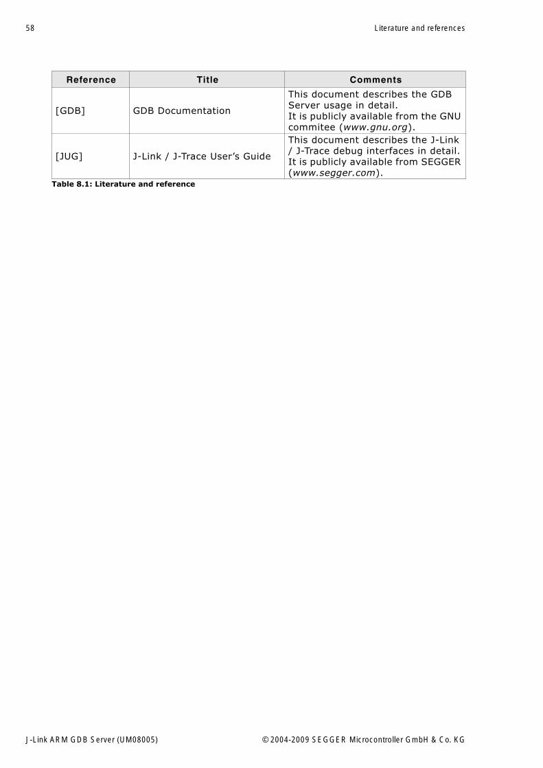
Reference Title Comments
[GDB] GDB Documentation
This document describes the GDB Server usage in detail.It is publicly available from the GNU commitee (www.gnu.org).
[JUG] J-Link / J-Trace User�s Guide
This document describes the J-Link / J-Trace debug interfaces in detail.It is publicly available from SEGGER (www.segger.com).
Table 8.1: Literature and reference
J-Link ARM GDB Server (UM08005) © 2004-2009 SEGGER Microcontroller GmbH & Co. KG
59
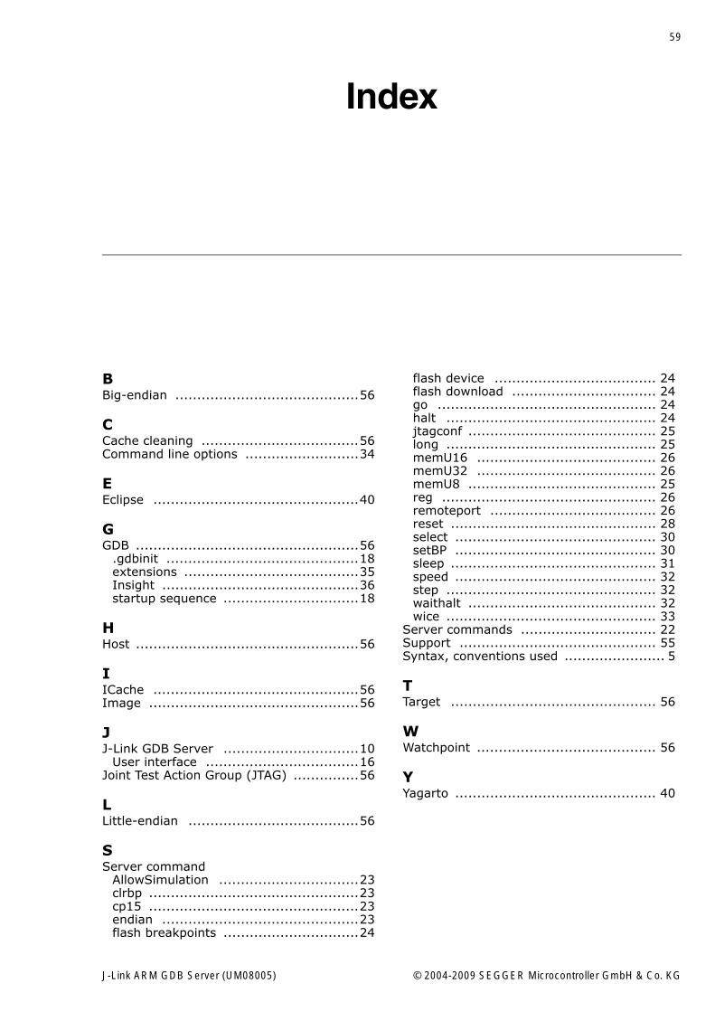
Index
BBig-endian ..........................................56
CCache cleaning ....................................56Command line options ..........................34
EEclipse ...............................................40
GGDB ...................................................56
.gdbinit ............................................18extensions ........................................35Insight .............................................36startup sequence ...............................18
HHost ...................................................56
IICache ...............................................56Image ................................................56
JJ-Link GDB Server ...............................10
User interface ...................................16Joint Test Action Group (JTAG) ...............56
LLittle-endian .......................................56
SServer command
AllowSimulation ................................23clrbp ................................................23cp15 ................................................23endian .............................................23flash breakpoints ...............................24
flash device ..................................... 24flash download ................................. 24go .................................................. 24halt ................................................ 24jtagconf ........................................... 25long ................................................ 25memU16 ......................................... 26memU32 ......................................... 26memU8 ........................................... 25reg ................................................. 26remoteport ...................................... 26reset ............................................... 28select .............................................. 30setBP .............................................. 30sleep ............................................... 31speed .............................................. 32step ................................................ 32waithalt ........................................... 32wice ................................................ 33
Server commands ............................... 22Support ............................................. 55Syntax, conventions used ....................... 5
TTarget ............................................... 56
WWatchpoint ......................................... 56
YYagarto .............................................. 40
J-Link ARM GDB Server (UM08005) © 2004-2009 SEGGER Microcontroller GmbH & Co. KG
60 Index
J-Link ARM GDB Server (UM08005) © 2004-2009 SEGGER Microcontroller GmbH & Co. KG


![MIT OpenCourseWare 6.189 Multicore …...Running Processes Under GDB ppu-gdb ./hello-world (gdb) run [args] … (gdb) quit export SPU_INFO=1 for extra information about threads Phil](https://img.pdfslide.net/doc/110x75/5f19ba63a6b0b957e67c7a59/mit-opencourseware-6189-multicore-running-processes-under-gdb-ppu-gdb-hello-world.jpg)


![GDB telux ver090906 - cs.tau.ac.il · (gdb) watch expr –stops whenever the value of the expression changes (gdb ) i b (gdb) clear [arg ] (gdb) delete [bnum ] Without arguments deletes](https://img.pdfslide.net/doc/110x75/5ae0abbc7f8b9ab4688daeeb/gdb-telux-ver090906-cstauacil-gdb-watch-expr-stops-whenever-the-value-of.jpg)