Embed Size (px)
Citation preview


1
JAEA-Review 2009-055
Investigation on Integrity of JMTR Concrete Structures,Cooling System and Utility Facilities
Hiroyuki EBISAWA, Kenji TOBITA, Akitomi FUKASAKU and Masanori KAMINAGA
Department of JMTR Operation, Neutron Irradiation and Testing Reactor Center,Oarai Research and Development Center
Japan Atomic Energy AgencyOarai-machi, Higashiibaraki-gun, Ibaraki-ken
(Received December 16, 2009)
The condition of facilities and components to be used for re-operation of the Japan Materials Testing Reactor (JMTR) from FY2011, was investigated before the refurbishment work. An investigation of aged components (aged-investigation) was carried out for concrete structures of the JMTR reactor building, exhaust stack, trench, canal, filter banks and for aged components of tanks in the primary cooling system, heat exchangers, pipes in the secondary cooling system, cooling tower, emergency generators and so on, in order to identify their integrity. The aged-investigation was carried out from the beginning of FY2007. As a result, cracks of concrete structures such as the exhaust stack, a foundation of the UCL (Utility Cooling Line) elevated water tank were repaired and pipe linings of secondary cooling system were replaced. Motors of primary cooling pumps, pumps in the secondary cooling system and in other systems were decided to replace from viewpoints of future maintenance and improvement of reliability. Other components and the reactor building were decided to use continuously for a long-term by appropriate maintenance activities based on the long-term maintenance plan. In this paper, the aged-investigation for the JMTR reactor building, heat exchangers and emergency generators is presented.
Keywords : JMTR, Testing Reactor, Refurbishment, Aged-Investigation, Concrete Structure,Cooling System
����������� ��������
�

2
JAEA-Review 2009-055
JMTR
(2009 12 16 )
2011 JMTR2007 JMTR
1 2
UCL 2
JMTR
311-1393 4002
����������� ��������
�

3
Contents
1. Introduction ---------------------------------------------------------------------------------------------------- 12. JMTR Reactor Building ------------------------------------------------------------------------------------- 1
2.1 Investigation Items ---------------------------------------------------------------------------------------- 22.2 Investigation Results ---------------------------------------------------------------------------------------- 2
3. Main Heat Exchangers ---------------------------------------------------------------------------------------- 53.1 Investigation Items ---------------------------------------------------------------------------------------- 53.2 Investigation Results ---------------------------------------------------------------------------------------- 5
4. Diesel Generators ----------------------------------------------------------------------------------------------- 64.1 Investigation Items ---------------------------------------------------------------------------------------- 64.2 Investigation Results ---------------------------------------------------------------------------------------- 6
5. Conclusions ------------------------------------------------------------------------------------------------------- 8References -------------------------------------------------------------------------------------------------------------- 8
Appendix Presentation materials at 2nd International Symposium on Material TestReactor ------------------------------------------------------------------------------------------------- 9
1. ------------------------------------------------------------------------------------------------------------ 12. JMTR -------------------------------------------------------------------------------------------- 1
2.1 ------------------------------------------------------------------------------------------------------ 22.2 -------------------------------------------------------------------------------------------------------- 2
3. ---------------------------------------------------------------------------------------------------------- 53.1 -------------------------------------------------------------------------------------------------------- 53.2 ----------------------------------------------------------------------------------------------------------- 5
4. ----------------------------------------------------------------------------------------------- 64.1 -------------------------------------------------------------------------------------------------------- 64.2 ----------------------------------------------------------------------------------------------------------- 6
5. -------------------------------------------------------------------------------------------------------------- 8----------------------------------------------------------------------------------------------------------------- 8
2 -------------------------------------- 9
�������������������
�

�����������������
���
�����������������
1
1. Introduction
The Japan Materials Testing Reactor (JMTR) located at Oarai Research &Development Center of Japan Atomic Energy Agency (JAEA) is a light water moderated and cooled, beryllium reflected tank- type reactor using LUE silicide plate-type fuels. Its thermal power is 50 MW. The construction of JMTR was began at 1965 in order to establish domestic technology for developing nuclear power plants and the first criticality was achieved in March 1968. Its operation for users was started from 1970 and was stopped August, 2006 for the refurbishment. During this period, the JMTR was operated 165 cycles. The refurbishment was started from the beginning of FY2007 and it will finish the end of FY2010. The renewed and upgraded JMTR will be re-started from FY2011.
The condition of facilities and components to be used for re-operation of the Japan Materials Testing Reactor (JMTR) from FY2011, was investigated before the refurbishment work. An investigation of aged components (aged-investigation) was carried out for concrete structures of the JMTR reactor building, exhaust stack, trench, canal, filter banks and for aged components of tanks in the primary cooling system, heat exchangers, pipes in the secondary cooling system, cooling tower, emergency generators and so on, in order to identify their integrity1). The aged-investigation was carried out from the beginning of FY2007. As a result, cracks of concrete structures such as the exhaust stack, a foundation of the UCL (Utility Cooling Line) elevated water tank were repaired and pipe linings of secondary cooling system were replaced. Motors of primary cooling pumps, pumps in the secondary cooling system and in other systems were decided to replace from viewpoints of future maintenance and improvement of reliability. Other components and the reactor building were decided to use continuously for a long-term by appropriate maintenance activities based on the long-term maintenance plan1).
In this paper, the aged-investigation for the JMTR reactor building, heat exchangers and emergency generators is described.
2. JMTR Reactor Building
Concrete structure of the JMTR reactor building was constructed from 1965 to 1967. After 17 years of the construction i.e., in 1983, strength, carbonation etc. of the JMTR reactor building concrete were investigated and the soundness of the JMTR reactor building was confirmed. At present, the JMTR reactor building has been used for more than 40 years after completion of the building and is used more than 20 years after the previous soundness investigation. The JMTR reactor building is to be used more than 20 years from now.
Therefore, concrete cracks, carbonation depth etc. were investigated in order to clarify
�������������������
���

2
the soundness of the JMTR reactor building concrete before refurbishment for re-operation of the JMTR from 2011.
2.1 Investigation ItemsThe investigation items and method of investigations for each investigation item are
summarized as follows.(1) Visual inspection
Crack, rust fluid, efflorescence, float and falling of masonry were visually observed. Crack scale was used for measuring cracks which have a width more than 0.3 mm.
Visual inspection and evaluation are carried out base on “Recommendations for Practice of Survey, Diagnosis and Repair for Deterioration of Reinforced Concrete Structures”2). After the visual inspection, cracks of concrete were repaired and the outer wall was painted.
(2) Compression strength of concrete (Destructive tests)Destructive tests (Core method using 10 cm drilled core samples) were carried out
based on “Method of sampling and testing for compressive strength of drilled cores of concrete (JIS A 1107(2002))”. Core boring was carried out by using a reinforced bar explorer in order to avoid cutting reinforced bar during drilling.
(3) Visual observation of reinforced bar corrosionVisual observation of reinforced bar corrosion was carried out based on
“Recommendations for Practice of Survey, Diagnosis and Repair for Deterioration of Reinforced Concrete Structures” 2) .
(4) Chloride ion content in concreteChloride ion content in concrete was measured based on “Methods of test for chloride ion
content in hardened concrete (JIS A 1154)”.(5) Carbonation depth of concrete
Carbonation depth of concrete was measured based on “Method for measuring carbonation depth of concrete (JIS A 1152)”.
2.2 Investigation Results(1) Visual inspection
No damage was observed for the outer wall. On the other hand, small cracks (maximum gap size is 0.4 mm), float of paint and falling of masonry were observed for a part of the inner wall.
(2) Compression strength of concrete (Destructive tests)As results of compression strength tests for 16 samples, average strength of 367.4
kgf/cm2 and minimum strength of 311 kgf/cm2 were obtained. There value meat the design basis strength of 210 kgf/cm2.
�������������������
���

3
(3) Visual observation of reinforced bar corrosionThe point rust was caused on the surface of 7 samples of 16 samples. The point rust
caused on the samples were estimated as “Corrosion grade I”, which do not affect concrete strength.
(4) Chloride ion content in concreteFig. 2.1 shows a chloride ion content measurement result as a function of depth. The
chloride ion content in concrete was kept below 0.2 kg/m3 which is the criterion value of JASS 5N3), at the position of the reinforced bar, even that of near the surface was greater than 0.2kg/m3. Chloride ion content near the surface has been increased by accumulating the coming flying salinity.
(5) Carbonation depth of concreteFig. 2.2 shows carbonation depth of inner wall and Fig. 2.3 shows carbonation depth of
outer wall. Carbonation of the inner wall didn’t become significant because of protection effect by wall paint. On the other hand, carbonation of the outer wall became significantgradually, but the maximum carbonation depth of 23mm was small enough against measured protection thickness of reinforced concrete (57 mm). Therefore, the concrete structure of the JMTR reactor building will keep its integrity more than 60 years accordingto the prediction by Kishitani correlation as shown in Fig. 2.3.
0.0
0.5
1.0
1.5
2.0
0 50 100 150
Chl
orid
e Io
n C
onte
nt (K
g/m
3 )
Sample Pick-up Position : Depth from the surface of concrete (mm)
Reactor Building Outside 1F : Chloride Ion Content
IC-29 (1F)
IC-32 (1F)
IC-34 (1F)
Measured protection thickness of reinforced concrete(Minimum value)
57 mm
Criterion for Maximum content of Chloride ion : 0.2 kg/m3
Sample number
Fig. 2.1 Chloride ion content as a function of depth
�������������������
���

4
0
20
40
60
80
100
0 20 40 60 80 100
Cab
onat
ion
dept
h (m
m)
Material age (Year)
Prediction by Kishitani correlation
Prediction by Morinaga correlation
Measured in FY 1983
Measured in FY 2007
Measured protection thickness of reinforced concrete : 76 (mm)
4)
5)
Fig. 2.2 Carbonation depth of inner wall
0
20
40
60
80
100
0 20 40 60 80 100
Car
bona
tion
dept
h (m
m)
Material age (Year)
Prediction by Kishitani correlation
Prediction by Morinaga correlation
Measured in FY 1983
Measued in FY 2007
Measured protection thickness of reinforced concrete : 57 (mm)
4)
5)
Fig. 2.3 Carbonation depth of outer wall
�������������������
���

5
3. Main Heat Exchangers
Primary cooling system consists of a main circulation loop and a purification loop. The main circulation loop removes heat generated in the core (50MW) and transfers it to the secondary cooling system. The primary cooling system has three main heat exchangers. A detailed investigation was carried out for the main heat exchangers of the primary cooling system. Table 3.1 shows major specifications of the main heat exchangers.
Table 3.1 Major specifications of the main heat exchangers
Dimension : 11,390 mm H x 1,650 mmTube material : SUS27TB
(SUS304,18%Cr, 8%Ni)Thickness of tube: 1.2 mmNumber of tubes : 1,152
3.1 Investigation ItemsThe investigation items were listed as follows.
(1) Eddy current testing for heat exchanger tubesThinning of the heat exchanger tube was measured by the eddy current testing.
(2) Thickness measurement of the main bodyWall thickness of the heat exchanger main body was measured by an ultrasonic thickness
gauge.(3) Visual observation using an endoscope
According to the eddy current testing, visual observation was carried out with an endoscope for the heat exchanger tube that had been evaluated as the thinning of the thinning rate 20% or more. Surface condition and color change of the tube were checked.
3.2 Investigation Results(1) Eddy current testing for heat exchanger tubes
10 tubes in Unit No.1, 6 tubes in Unit No.2 and 7 tubes in Unit No.3 were evaluated to have the thinning rate 20% or more. All of these thinning was observed at the inner surface of the tube wall.(2) Thickness measurement of the main body
All measured thickness were greater than required minimum thickness of 6 mm.(3) Visual observation using an endoscope
Surface condition and color change of the tubes which had been evaluated as the thinning of the thinning rate 20% or more, were checked. No evidence of abnormal condition was observed.
�������������������
���

6
4. Diesel Generators
Electric power supply system of the JMTR consists of a commercial power supply system and an emergency power supply system. The emergency power supply system consists of diesel generators (2 units) and batteries. To confirm the integrity of the diesel generators, the insulation diagnosis examination of the dynamo stator coil (high voltage) was carried out.
Table 4.1 Major specifications of the diesel generators
Type : 3-phase brushless alternatorRated output : 1,750 KVAVoltage : 6,600 VLoad current : 153AFrequency : 50Hz
4.1 Investigation ItemsThe investigation items were listed as follows.
(1) Insulation resistance testThe insulation resistance was measured by adding direct voltage between ground the
alternator.(2) Dielectric dissipation factor test
The voltage and the phase of leakage current were measured by adding alternating voltage between ground the alternator.(3) Alternating current test
The voltage and the linearity of the leakage current were measured by adding alternating voltage between ground and the alternator.(4) Partial discharge test
The amount of the partial electrical discharge generated at the coil was measured by adding alternating voltage between ground and the alternator.
4.2 Investigation Results(1) Insulation resistance test
There was no surface leakage of current was measured as shown in Figs. 4.1 and 4.2. There is no deterioration of insulation resistance caused by moisture uptake.(2) Dielectric dissipation factor test
There was no evidence of the moisture uptake of the stator coil, the stain, changing in quality, flaking off. No void was generated.
�������������������
���

7
1.0E+03
1.0E+04
1.0E+05
1 2 3 4 5 6
Insu
latio
n re
sist
ance
[M
Impressed voltage [kV]
DG-1
Fig. 4.1 Insulation resistance for DG-1
1.0E+03
1.0E+04
1.0E+05
1 2 3 4 5 6
Insu
latio
n re
sist
ance
[M
Impressed voltage [kV]
DG-2
Fig. 4.2 Insulation resistance for DG-2
(3) Alternating current testThere was no void caused by flaking off and the breakdown voltage was measured to be
6.6KV or more.(4) Partial discharge test
There was no harmful partial discharge, and was no evidence of existing void.
�������������������
���

8
5. Conclusions
An aged-investigation was carried out for concrete structures, cooling systems and the utility facilities that will be continuously used in the future operation of the JMTR, at the beginning of a long-term shut-down period for the repairing or replacement work of the JMTR related facilities.
As a result, it was confirmed that it was possible to use most of those facilities or components continuously. A small aged effect was found in a part of the concrete structure of the JMTR reactor building.
Therefore, cracks of concrete were repaired and the outer wall was painted. Thus the long-term integrity of the concrete structures and the JMTR related facilities was established.
“Facilities and components “ which are identified as having aged effects by the aged-investigation, will be maintained by the periodical maintenance activities based on the "Long-term maintenance plan" in the future.
References
1) H.Ebisawa et al., “The Outline of Investigation on Integrity of JMTR Concrete Structures, Cooling System and Utility Facilities”, JAEA-Technology 2009-030(2009).2) Architectural Institute of Japan, “Recommendations for Practice of Survey, Diagnosis and Repair for Deterioration of Reinforced Concrete Structures”, (1997).3) Architectural Institute of Japan, “Japanese Architectural Standard Specification JASS 5N Reinforced Concrete Work at Nuclear Power Plants”, (1999).4) Architectural Institute of Japan, “Recommendations for Design and Construction Practice of High Durable Concrete”,(1991).5) S. Morinaga, “Research on life prediction of reinforced concrete building based on corrosion rating of reinforced concrete”, Thesis, University of Tokyo, (1986).
�������������������
���

9
Appendix Presentation materials at 2nd International Symposium on Material Test Reactor
The 2nd International Symposium on Material Test Reactors was held September 28 –October 1, 2009 at the Hilton Garden Inn hotel in Idaho Falls, Idaho, US. The objective of the meeting was to provide an opportunity for technical and operational information exchange among international test reactor facilities.
The presentation materials related in “Investigation on Integrity of JMTR Concrete Structures, Cooling System and Utility Facilities” are attached as an appendix.
�������������������
���

Investigation on Integrity of JMTRInvestigation on Integrity of JMTRg g yg g yConcrete Structures, Cooling SystemConcrete Structures, Cooling System
d U ili F ili id U ili F ili iand Utility Facilitiesand Utility Facilities
H.H. EbisawaEbisawa, K. Tobita, A. , K. Tobita, A. FukasakuFukasaku and M. and M. KaminagaKaminaga
Neutron Irradiation and Testing Reactor Center,Neutron Irradiation and Testing Reactor Center,Department of JMTR Operation,Department of JMTR Operation,Department of JMTR Operation,Department of JMTR Operation,
OaraiOarai Research and Development CenterResearch and Development CenterJapan Atomic Energy Research Agency (JAEA)Japan Atomic Energy Research Agency (JAEA)
JMTR Refurbishment ProjectJMTR Refurbishment Project
The JMTR was constructed in order to perform irradiation The JMTR was constructed in order to perform irradiation tests for LWR fuels materials and to produce radio isotopestests for LWR fuels materials and to produce radio isotopestests for LWR fuels, materials and to produce radio isotopes.tests for LWR fuels, materials and to produce radio isotopes.The construction of the JMTR was began 1965.The construction of the JMTR was began 1965.
Operation was stopped August 2006.Operation was stopped August 2006.((The JMTR was used for about 40 years.The JMTR was used for about 40 years.))((The JMTR was used for about 40 years.The JMTR was used for about 40 years.))
Future utilization of the JMTR was investigated.Future utilization of the JMTR was investigated.
ReRe--operation from FY2011 was decided.operation from FY2011 was decided.((The JMTR will be utilized more than 20 years.The JMTR will be utilized more than 20 years.))
f f ff f f1
Refurbishment of the JMTR was started from FY2007.Refurbishment of the JMTR was started from FY2007.
�������������������
����

Purpose of the AgedPurpose of the Aged--InvestigationInvestigation
An investigation of aged components (An investigation of aged components (agedaged--investigationinvestigation))An investigation of aged components (An investigation of aged components (agedaged investigationinvestigation))was performed at the beginning of 2007 as a part of the was performed at the beginning of 2007 as a part of the JMTR refurbishment projectJMTR refurbishment project..
TheThe agedaged--investigationinvestigation was performed in order to identifywas performed in order to identifygg gg p yp yintegrity of facilities and components to be used for reintegrity of facilities and components to be used for re--operation of JMTR.operation of JMTR.
Based on the Based on the agedaged--investigationinvestigation results, future results, future i ti t f h f ilit t i tf h f ilit t i tmaintenance program maintenance program for each facility or component is tofor each facility or component is to
bebe reconsideredreconsidered. If necessary, . If necessary, repairingrepairing oror replacementreplacementof facilities or components is to be carried outof facilities or components is to be carried outof facilities or components is to be carried out.of facilities or components is to be carried out.
2
AgedAged--InvestigationInvestigation
Following concrete structures and components were Following concrete structures and components were investigated in order to identify their integrity.investigated in order to identify their integrity.investigated in order to identify their integrity.investigated in order to identify their integrity.
1.1. JMTR reactor buildingJMTR reactor building, Exhaust stack : Concrete, Exhaust stack : Concrete2.2. Trench, canal, filter banks : ConcreteTrench, canal, filter banks : Concrete3.3. Pressure vessel Pressure vessel 4.4. Diaphragm of the reactor poolDiaphragm of the reactor pool55 UCL (Utility Cooling Loop) elevated water tankUCL (Utility Cooling Loop) elevated water tank5.5. UCL (Utility Cooling Loop) elevated water tankUCL (Utility Cooling Loop) elevated water tank6.6. Main heat exchangers of the primary cooling systemMain heat exchangers of the primary cooling system7.7. Surge tank, Purify water tank, Degas tankSurge tank, Purify water tank, Degas tank7.7. Surge tank, Purify water tank, Degas tankSurge tank, Purify water tank, Degas tank8.8. Secondary cooling system pipes, Cooling towerSecondary cooling system pipes, Cooling tower9.9. Canal expansion jointCanal expansion joint10.10. Diesel generators (Emergency generators)Diesel generators (Emergency generators)
In this presentation, the agedIn this presentation, the aged--investigation results of the investigation results of the JMTR reactor building main heat exchangers andJMTR reactor building main heat exchangers andJMTR reactor building, main heat exchangers andJMTR reactor building, main heat exchangers andemergency generators are presented. emergency generators are presented.
3
�������������������
����
Schedule for AgedSchedule for Aged--InvestigationInvestigation
Jan Feb Mar Apr May Jun Jul Aug Sep Oct Nov Dec Jan Feb Mar
Work schedule for the aged-investigation
No. Item FY 2006 FY 2007
1 JMTR reactor
2Exhaust stack,Trench, canal,
filter banks
1 building
3 Pressure vessel
4 Diaphragm of thereactor pool
5 Elevated water tankof UCL
6 Main heatexchangers
7Surge tank,
Purify water tank,Degas tank
8 Secondary coolingsystem pipes
8' Cooling tower
9 Canal expansionjoint
410
Diesel generator(Emergencygenerator)
JMTR Reactor Building (1/3)JMTR Reactor Building (1/3)
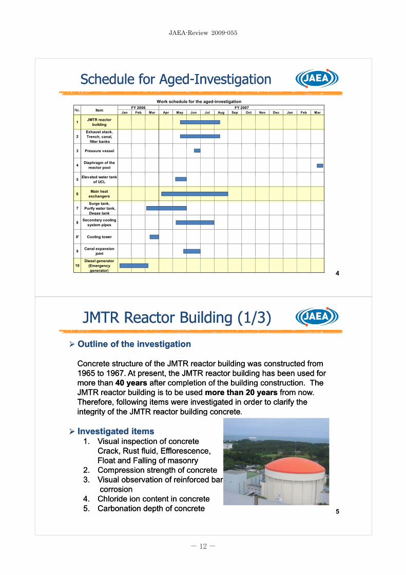
Outline of the investigationOutline of the investigation
Concrete structure of the JMTR reactor building was constructed from Concrete structure of the JMTR reactor building was constructed from 1965 to 1967. At present, the JMTR reactor building has been used for 1965 to 1967. At present, the JMTR reactor building has been used for more than more than 40 years40 years after completion of the building construction. The after completion of the building construction. The yy p gp gJMTR reactor building is to be used JMTR reactor building is to be used more than 20 yearsmore than 20 years from now.from now.Therefore, following items were investigated in order to clarify the Therefore, following items were investigated in order to clarify the integrity ofintegrity of the JMTR reactor building concretethe JMTR reactor building concreteintegrity ofintegrity of the JMTR reactor building concretethe JMTR reactor building concrete
Investigated itemsInvestigated items11 Visual inspection of concreteVisual inspection of concrete1.1. Visual inspection of concreteVisual inspection of concrete
Crack, Rust fluid, Efflorescence,Crack, Rust fluid, Efflorescence,Float and Falling of masonryFloat and Falling of masonry
22 C i t th f tC i t th f t2.2. Compression strength of concreteCompression strength of concrete3.3. Visual observation of reinforced barVisual observation of reinforced bar
corrosioncorrosion4.4. Chloride ion content in concreteChloride ion content in concrete5.5. Carbonation depth of concreteCarbonation depth of concrete 5
�������������������
����

JMTR Reactor Building (2/3)JMTR Reactor Building (2/3)
Investigation resultsInvestigation results11 Visual InspectionVisual Inspection1.1. Visual InspectionVisual Inspection
No damage was observed for the No damage was observed for the outer wallouter wall. On the other hand, . On the other hand, small cracks (maximum gap size is small cracks (maximum gap size is 0.4 mm0.4 mm) , float of paint and ) , float of paint and f lli f b d f t f thf lli f b d f t f th i lli llfalling of masonry were observed for a part of thefalling of masonry were observed for a part of the inner wallinner wall..
22 Compression strength of concreteCompression strength of concrete2.2. Compression strength of concreteCompression strength of concreteCompression strength of concrete was investigated for 16 Compression strength of concrete was investigated for 16 samples. All the measured results of compression strength were samples. All the measured results of compression strength were
t th th d i b i t th ft th th d i b i t th f 210 k f/ 2greater than the design basis strength ofgreater than the design basis strength of 210 kgf/cm2..
33 Visual observation of reinforced bar corrosionVisual observation of reinforced bar corrosion3.3. Visual observation of reinforced bar corrosionVisual observation of reinforced bar corrosionThe point rust was caused on the surface of 7 samples of 16 The point rust was caused on the surface of 7 samples of 16 samples. (Corrosion grade I ) samples. (Corrosion grade I ) No problemNo problem
6
JMTR Reactor Building (3/3)JMTR Reactor Building (3/3)
Investigation results (Continue)Investigation results (Continue)4.4. Chloride ion content in concreteChloride ion content in concrete
Chloride ion content in concrete was kept Chloride ion content in concrete was kept below below 0.2 kg/m0.2 kg/m3 which is which is the criterion value of the criterion value of JASS 5NJASS 5N*, at the position of the reinforced bar.*, at the position of the reinforced bar.
** Japanese Architectural Standard Specification JASS 5N Reinforced Concrete Japanese Architectural Standard Specification JASS 5N Reinforced Concrete Work at Nuclear Power Plants . Work at Nuclear Power Plants .
5.5. Carbonation depth of concreteCarbonation depth of concreteCarbonation of Carbonation of the inner wallthe inner wall didn’t become worth because of didn’t become worth because of protection effect by wall paint. On the other hand, carbonation of protection effect by wall paint. On the other hand, carbonation of the outer wall became worth gradually, but the maximum measured the outer wall became worth gradually, but the maximum measured carbonation depth was small enough against measured protectioncarbonation depth was small enough against measured protectionp g g pp g g pthickness of reinforced concrete (thickness of reinforced concrete (57 mm57 mm).).
7
�������������������
����

Main Heat Exchanger (1/2)Main Heat Exchanger (1/2)
Outline of the investigationOutline of the investigationA detailed investigation was carried out for the main heat exchangers of the A detailed investigation was carried out for the main heat exchangers of the primary cooling systemprimary cooling systemMajor specifications (3 Units)Major specifications (3 Units)Dimension : 11,390 mm H x 1,650 Dimension : 11,390 mm H x 1,650 mmmmφφTube material : SUS27TB Tube material : SUS27TB (SUS304,18%Cr, 8%Ni)(SUS304,18%Cr, 8%Ni)Thickness of tube : 1.2 mmThickness of tube : 1.2 mmNumber of tubes : 1,152Number of tubes : 1,152Investigated itemsInvestigated items
1.1. Eddy current testingEddy current testing for heat exchanger tubesfor heat exchanger tubesThinning of the heat exchanger tube was measuredThinning of the heat exchanger tube was measuredby the eddy current testing. by the eddy current testing.
2.2. Thickness measurement of the main bodyThickness measurement of the main bodyWall thickness of the heat exchanger main body was measured by an Wall thickness of the heat exchanger main body was measured by an
lt i thi klt i thi kultrasonic thickness gaugeultrasonic thickness gauge..3.3. Visual observation using an endoscopeVisual observation using an endoscope
According to the eddy current testing, visual observation was carried out with According to the eddy current testing, visual observation was carried out with anan endoscopeendoscope for the heat exchanger tube that had been evaluated as thefor the heat exchanger tube that had been evaluated as theanan endoscopeendoscope for the heat exchanger tube that had been evaluated as thefor the heat exchanger tube that had been evaluated as thethinning of the thinning rate 20% or more. Surface condition and color change thinning of the thinning rate 20% or more. Surface condition and color change of the tube were checked. of the tube were checked. 8
Main Heat Exchanger (2/2)Main Heat Exchanger (2/2)
Investigation resultsInvestigation results1.1. Eddy current testingEddy current testing for heat exchanger tubesfor heat exchanger tubesy gy g gg
10 tubes in Unit No.1, 6 tubes in Unit No.2 and 10 tubes in Unit No.1, 6 tubes in Unit No.2 and 7 tubes in Unit No.3 were evaluated to have the 7 tubes in Unit No.3 were evaluated to have the thinning rate 20% or morethinning rate 20% or more
Eddy current testing for
thinning rate 20% or more.thinning rate 20% or more.Thinning was observed at the inner surface of Thinning was observed at the inner surface of the tube wall.the tube wall. y g
heat exchanger tubes2.2. Thickness measurement of the main bodyThickness measurement of the main bodyAll measured thickness were greater than All measured thickness were greater than required minimum thickness ofrequired minimum thickness of 6 mm6 mmrequired minimum thickness ofrequired minimum thickness of 6 mm6 mm..
3.3. Visual observation using an endoscopeVisual observation using an endoscopeSurface condition and color change of the Surface condition and color change of the
Thickness measurement by
ggtubes which had been evaluated as the thinning tubes which had been evaluated as the thinning of the thinning rate 20% or more, were checked. of the thinning rate 20% or more, were checked. No evidence of abnormal condition wasNo evidence of abnormal condition was Thickness measurement by
the ultrasonic thickness gaugeNo evidence of abnormal condition wasNo evidence of abnormal condition wasobserved. observed. No problemNo problem
9
�������������������
����

Diesel Generator (1/2)Diesel Generator (1/2)Outline of the investigationOutline of the investigationTo confirm the integrity of the diesel generator, the insulation diagnosis To confirm the integrity of the diesel generator, the insulation diagnosis examination of the dynamo stator coil (high voltage) was carried out.examination of the dynamo stator coil (high voltage) was carried out.examination of the dynamo stator coil (high voltage) was carried out.examination of the dynamo stator coil (high voltage) was carried out.Major specificationsMajor specificationsType: 3Type: 3--phase brushless alternator,phase brushless alternator,Rated output 1 750 KVA Voltage : 6 600Rated output 1 750 KVA Voltage : 6 600 VVRated output 1,750 KVA, Voltage : 6,600Rated output 1,750 KVA, Voltage : 6,600 V,V,Load current : 153A, Frequency: 50Hz Load current : 153A, Frequency: 50Hz Investigated itemsInvestigated items11 The insulation resistance testThe insulation resistance test1.1. The insulation resistance testThe insulation resistance test
The insulation resistance was measuredThe insulation resistance was measuredby adding direct voltage between groundby adding direct voltage between groundthe alternator.the alternator. Di l G N 2 (DG 2)the alternator.the alternator.
2.2. TheThe dissipation factor dissipation factor testtestThe voltage and the phase of leakage current were measured by adding alternating The voltage and the phase of leakage current were measured by adding alternating voltage between ground the alternator. voltage between ground the alternator.
Diesel Generator No.2 (DG-2)
3.3. The alternating current testThe alternating current testThe voltage and the linearity of the leakage current were measured by adding The voltage and the linearity of the leakage current were measured by adding alternating voltage between ground and the alternator. alternating voltage between ground and the alternator.
44 Th ti l di h t tTh ti l di h t t4.4. The partial discharge testThe partial discharge testThe amount of the partial electrical discharge generated at the coil was measured by The amount of the partial electrical discharge generated at the coil was measured by adding alternating voltage between ground and the alternator. adding alternating voltage between ground and the alternator. 10
Diesel Generator (2/2)Diesel Generator (2/2)
Investigation resultsInvestigation results1.1. The insulation resistance testThe insulation resistance test
There was no surface leakage of current There was no surface leakage of current was measured(see figures). There is no was measured(see figures). There is no deterioration of insulation resistance deterioration of insulation resistance caused by moisture uptakecaused by moisture uptakecaused by moisture uptake.caused by moisture uptake.
2.2. TheThe dissipation factor dissipation factor testtestThere was no evidence of the moistureThere was no evidence of the moistureThere was no evidence of the moistureThere was no evidence of the moistureuptake of the stator coil, the stain, uptake of the stator coil, the stain, changing in quality, flaking off. No void changing in quality, flaking off. No void was generated.was generated.
Insulation resistance for DG-1
gg
3.3. The alternating current testThe alternating current testThere was no void caused by flaking off There was no void caused by flaking off and the breakdown voltage was and the breakdown voltage was measured to be 6.6KV or more.measured to be 6.6KV or more.
44 Th ti l di h t tTh ti l di h t t4.4. The partial discharge testThe partial discharge testThere was no harmful partial discharge, There was no harmful partial discharge, and was no evidence of existing void. and was no evidence of existing void. Insulation resistance for DG-2 11
�������������������
����

ConclusionConclusion
An agedAn aged--investigation was carried out for concrete structures, cooling investigation was carried out for concrete structures, cooling t d th tilit f iliti th t ill b ti l d i th f tt d th tilit f iliti th t ill b ti l d i th f tsystems and the utility facilities that will be continuously used in the futuresystems and the utility facilities that will be continuously used in the future
operation of the JMTR, at the beginning of a longoperation of the JMTR, at the beginning of a long--term shutterm shut--down period down period for the repairing or replacement work of the JMTR related facilities.for the repairing or replacement work of the JMTR related facilities.
As a result, it was confirmed that it was possible to use most of those As a result, it was confirmed that it was possible to use most of those facilities or components continuously. A small aged effect was found in a facilities or components continuously. A small aged effect was found in a part of the equipment such as the secondary cooling system pipes linings,part of the equipment such as the secondary cooling system pipes linings,part of the equipment such as the secondary cooling system pipes linings,part of the equipment such as the secondary cooling system pipes linings,the secondary cooling towers, etc.the secondary cooling towers, etc.
Therefore, cracks of concrete and a part of the secondary cooling tower, Therefore, cracks of concrete and a part of the secondary cooling tower, etc., were repaired. The linings of the secondary cooling system pipes etc., were repaired. The linings of the secondary cooling system pipes were replaced. Thus the longwere replaced. Thus the long--term integrity of the concrete structures and term integrity of the concrete structures and the JMTR related facilities was established. the JMTR related facilities was established.
“Facilities and components “ which are identified as having aged effects by “Facilities and components “ which are identified as having aged effects by the agedthe aged--investigation, will be maintained by the periodical maintenance investigation, will be maintained by the periodical maintenance activities based on the "Longactivities based on the "Long--term maintenance plan" in the futureterm maintenance plan" in the futureactivities based on the Longactivities based on the Long--term maintenance plan in the future.term maintenance plan in the future.
12
AppendixAppendixAppendixAppendix
13
�������������������
����

Appendix. 1 JMTR Reactor BuildingAppendix. 1 JMTR Reactor Building-- Chloride ion content in concreteChloride ion content in concrete
Investigation results Investigation results Chloride ion content in concreteChloride ion content in concreteChloride ion content in concrete was kept Chloride ion content in concrete was kept below below 0.2 kg/m0.2 kg/m3 which is which is the criterion value of the criterion value of JASS 5NJASS 5N*, at the position of the reinforced bar, *, at the position of the reinforced bar, even that of near the surface was greater thaneven that of near the surface was greater than 0 2kg/m0 2kg/m3 ChlorideChlorideeven that of near the surface was greater thaneven that of near the surface was greater than 0.2kg/m0.2kg/m3.. ChlorideChlorideion content near the surface ion content near the surface has been increased by accumulating has been increased by accumulating the coming flying salinity.the coming flying salinity.
** Japanese Architectural Standard Japanese Architectural Standard Specification JASS 5N Specification JASS 5N Reinforced Concrete Work at Reinforced Concrete Work at Nuclear Power PlantsNuclear Power Plants
MarginMarginNuclear Power Plants . Nuclear Power Plants .
14
Appendix. 1 JMTR Reactor BuildingAppendix. 1 JMTR Reactor Building-- Carbonation depth of concreteCarbonation depth of concrete
Investigation results Investigation results Carbonation depth of concreteCarbonation depth of concreteCarbonation depth of concreteCarbonation depth of concreteCarbonation of Carbonation of the inner wallthe inner wall didn’t become worth because of didn’t become worth because of protection effect by wall paint. On the other hand, carbonation of protection effect by wall paint. On the other hand, carbonation of the outer wall became worth gradually, but the maximum the outer wall became worth gradually, but the maximum carbonation depth of carbonation depth of 23mm23mm was small enough against measured was small enough against measured protection thickness of reinforced concrete (protection thickness of reinforced concrete (57 mm57 mm).).
MarginMarginMarginMargin
Carbonation depth of the outer wallCarbonation depth of the outer wallCarbonation depth of the inner wallCarbonation depth of the inner wall 15
�������������������
����
Appendix. 2 Reactor Vessel (1/2)Appendix. 2 Reactor Vessel (1/2)
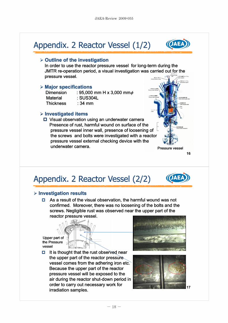
Outline of the investigationOutline of the investigationIn order to use the reactor pressure vessel for longIn order to use the reactor pressure vessel for long--term during the term during the JMTR reJMTR re--operation period, a visual investigation was carried out for the operation period, a visual investigation was carried out for the pressure vesselpressure vessel
Major specificationsMajor specificationsDimension : 95,000 mm H x 3,000 Dimension : 95,000 mm H x 3,000 mmmmφφMaterial : SUS304LMaterial : SUS304LMaterial : SUS304LMaterial : SUS304LThickness : 34 mmThickness : 34 mm
Investigated itemsInvestigated itemsInvestigated itemsInvestigated itemsVisual observation using an underwater cameraVisual observation using an underwater cameraPresence of rust, Presence of rust, harmful wound on surface of harmful wound on surface of the the
l i ll f l i fl i ll f l i fpressure vessel inner wall, presence of loosening ofpressure vessel inner wall, presence of loosening ofthe screws and bolts were investigated with a reactorthe screws and bolts were investigated with a reactorpressure vessel external checking device with thepressure vessel external checking device with theunderwater camera.underwater camera.
16Pressure vesselPressure vessel
Appendix. 2 Reactor Vessel (2/2)Appendix. 2 Reactor Vessel (2/2)
Investigation resultsInvestigation resultsAs a result of the visual observation, the harmful wound was not As a result of the visual observation, the harmful wound was not ,,confirmed. Moreover, there was no loosening of the bolts and the confirmed. Moreover, there was no loosening of the bolts and the screws. Negligible rust was observed near the upper part of the screws. Negligible rust was observed near the upper part of the reactor pressure vesselreactor pressure vesselreactor pressure vessel.reactor pressure vessel.
Upper part of Upper part of the Pressure the Pressure vesselvessel
It is thought that the rust observed near It is thought that the rust observed near the upper part of the reactor pressure the upper part of the reactor pressure vessel comes from the adhering iron etcvessel comes from the adhering iron etc
vesselvessel
vessel comes from the adhering iron etc.vessel comes from the adhering iron etc.Because the upper part of the reactor Because the upper part of the reactor pressure vessel will be exposed to the pressure vessel will be exposed to the i d i th t h ti d i th t h t d i d id i d i
17
air during the reactor shutair during the reactor shut--down period indown period inorder to carry out necessary work for order to carry out necessary work for irradiation samples.irradiation samples.
�������������������
����

Appendix. 3 Diaphragm of Reactor PoolAppendix. 3 Diaphragm of Reactor Pool
Outline of the investigationOutline of the investigationA diaphragm seal of the reactor pool was visually investigated in order to A diaphragm seal of the reactor pool was visually investigated in order to confirm its integrity by the inspection equipment with underwater camera.confirm its integrity by the inspection equipment with underwater camera.The diaphragm was located in the reactor pool bottom of about 10 m in The diaphragm was located in the reactor pool bottom of about 10 m in depth and it was impossible to observe from the water surface.depth and it was impossible to observe from the water surface.depth and it was impossible to observe from the water surface.depth and it was impossible to observe from the water surface.Investigated itemsInvestigated items
Visual observation usingVisual observation usingan underwater cameraan underwater cameraan underwater cameraan underwater cameraPresence of rust, Presence of rust, harmful woundharmful woundon surface of on surface of the diaphragm sealthe diaphragm seal
i ti t d b th i tii ti t d b th i tiwere investigated by the inspectionwere investigated by the inspectionequipment with underwater camera. equipment with underwater camera.
Investigated resultsInvestigated resultsAs a result of the visual observation,As a result of the visual observation,the harmful wound and rusts was notthe harmful wound and rusts was notconfirmed.confirmed.
Surface of the diaphragm sealSurface of the diaphragm seal
18
Appendix. 4 Elevated water tank of UCL (1/2)Appendix. 4 Elevated water tank of UCL (1/2)
Outline of the investigationOutline of the investigationTo confirm the integrity of the UCL(Utility Cooling Loop) elevated tank, To confirm the integrity of the UCL(Utility Cooling Loop) elevated tank, UCL elevated water tank base bolts, the surrounding plate, and the UCL elevated water tank base bolts, the surrounding plate, and the base plate were investigated. base plate were investigated.
Investigated itemsInvestigated items1.1. Base boltsBase bolts
(1) Visual inspection(1) Visual inspection(1) Visual inspection(1) Visual inspectionPaints, surface condition after rust flakes offPaints, surface condition after rust flakes off
(2) Size measurement(2) Size measurementConfirmation of corrosion thinning ratioConfirmation of corrosion thinning ratioConfirmation of corrosion thinning ratioConfirmation of corrosion thinning ratio
2.2. Surrounding plate, Base plateSurrounding plate, Base plate(1) Visual inspection(1) Visual inspection
P i t f diti ft t fl k ffP i t f diti ft t fl k ffPaints, surface condition after rust flakes offPaints, surface condition after rust flakes off(2) Magnetic particle testing (2) Magnetic particle testing
Confirmation of welding joint Confirmation of welding joint (3) Size measurement(3) Size measurement
Confirmation of corrosion thinning ratioConfirmation of corrosion thinning ratio 19
�������������������
����

Appendix. 4 Elevated water tank of UCL (2/2)Appendix. 4 Elevated water tank of UCL (2/2)
Investigated resultsInvestigated results1.1. Base boltsBase bolts
(1) Vi l i ti(1) Vi l i ti(1) Visual inspection(1) Visual inspectionThere were flaking off and floating of the paints.There were flaking off and floating of the paints.
(2) Size measurement(2) Size measurementThere was one bolt that had the maximum thinning rate of 7.34mmThere was one bolt that had the maximum thinning rate of 7.34mm(44.45mm 37.11mm) as a result of measuring 4 thinning bolts in 48 all bolts. (44.45mm 37.11mm) as a result of measuring 4 thinning bolts in 48 all bolts.
2.2. Surrounding plate, Base plateSurrounding plate, Base plate(1) Visual inspection(1) Visual inspection
There were flaking off and floating of the paints.There were flaking off and floating of the paints.g g pg g p(2) Magnetic particle testing (2) Magnetic particle testing
There is no evidence of crack and There is no evidence of crack and falsefalseindicationindication in the welding region.in the welding region.
Removing paints and rusts Removing paints and rusts from the investigation partfrom the investigation part
g gg g(3) Size measurement(3) Size measurement
There was no remarkable thinning in otherThere was no remarkable thinning in otherparts though there was thinning of 4.1mmparts though there was thinning of 4.1mmparts though there was thinning of 4.1mmparts though there was thinning of 4.1mm(22.0mm 17.9mm) on a part of the base(22.0mm 17.9mm) on a part of the baseplate in the spot at maximum.plate in the spot at maximum.
After repairing and paintsAfter repairing and paints20
Appendix. 5 Surge tank, Purify water tank,Appendix. 5 Surge tank, Purify water tank,Degas tank (1/2)Degas tank (1/2)
Outline of the investigationOutline of the investigationIn the primary cooling system, there are a surge tank, a purify water tank and a In the primary cooling system, there are a surge tank, a purify water tank and a
f ff fdegas tank. All these tanks will be used for during reoperation period. Therefore,degas tank. All these tanks will be used for during reoperation period. Therefore,an investigation was carried out for these tanks in order to identify their integrity.an investigation was carried out for these tanks in order to identify their integrity.Investigated itemsInvestigated items
1.1. Visual inspection (Including inside structures)Visual inspection (Including inside structures)2.2. PenetrantPenetrant testing (PT) for welding regiontesting (PT) for welding region
Surge tankSurge tank3950 mm H x 1028 mm 3950 mm H x 1028 mm φφ
Purify water tankPurify water tank3160 mm H x 1486 mm 3160 mm H x 1486 mm φφ
Degas tankDegas tank6200 mm H x 1566 mm 6200 mm H x 1566 mm φφ 21
�������������������
����

Appendix. 5 Surge tank, Purify water tank,Appendix. 5 Surge tank, Purify water tank,Degas tank (2/2)Degas tank (2/2)
Investigation resultsInvestigation results
1.1. Visual inspection (Including inside structures)Visual inspection (Including inside structures)Th b l diti i th i id f ll th t k fTh b l diti i th i id f ll th t k fThere was no abnormal condition in the inside of all three tanks ofThere was no abnormal condition in the inside of all three tanks ofthe surge tank, the purify water tank and the degas tank.the surge tank, the purify water tank and the degas tank.
2.2. PenetrantPenetrant testing (PT) for welding regiontesting (PT) for welding regionNo false indication was found in the surge tank. No false indication was found in the surge tank.
FFalse indications were observed in the welding lines of the purified alse indications were observed in the welding lines of the purified water tank and the degas tank. But after grinding, no falsewater tank and the degas tank. But after grinding, no falsewater tank and the degas tank. But after grinding, no falsewater tank and the degas tank. But after grinding, no falseindication was found in the reindication was found in the re--inspection. Therefore, it was inspection. Therefore, it was confirmed that they were not progressive defect.confirmed that they were not progressive defect. No problemNo problem
22
Appendix. 6 Secondary Cooling systemAppendix. 6 Secondary Cooling system-- Main pipes (1/2)Main pipes (1/2)
Outline of the investigationOutline of the investigationThe main pipes of the secondary cooling systemThe main pipes of the secondary cooling systemp p y g yp p y g yare made of the ordinary steel, and inside of the are made of the ordinary steel, and inside of the pipes are covered by resin linings for protecting pipes are covered by resin linings for protecting against rusts. Therefore, the lining check in the against rusts. Therefore, the lining check in the pipes was carried out in order to check the lining pipes was carried out in order to check the lining condition.condition.
Secondary cooling systemSecondary cooling systemInvestigated itemsInvestigated items
Visual observationVisual observation(1) Observation objects(1) Observation objects
Secondary cooling systemSecondary cooling systempipes 450Apipes 450A
Linings of the secondary cooling pipes ofLinings of the secondary cooling pipes of450A and 750A.450A and 750A.
(2) Observation method(2) Observation methodAs for 750A pipes, the investigator entered inAs for 750A pipes, the investigator entered inpipe and the lining was visually inspected bypipe and the lining was visually inspected bywatching . As for 450A pipes, the fiberscopewatching . As for 450A pipes, the fiberscope
d f th t hi d id f th t hi d iwas used for the watching device.was used for the watching device. Secondary cooling system Secondary cooling system pipes 750Apipes 750A
23
�������������������
����

Appendix. 6 Secondary Cooling systemAppendix. 6 Secondary Cooling system-- Main pipes (2/2)Main pipes (2/2)
Investigation resultsInvestigation resultsAs a result of the visual observation, the lining of the secondaryAs a result of the visual observation, the lining of the secondary, g y, g ycooling system pipes had swelling and cracks overall and the aged cooling system pipes had swelling and cracks overall and the aged deterioration of the lining progressed. deterioration of the lining progressed.
Repair of the lining has been carried outRepair of the lining has been carried outRepair of the lining has been carried out.Repair of the lining has been carried out.
There was no corrosion or thinning of the pipes.There was no corrosion or thinning of the pipes.g p pg p p
R k bl l kR k bl l k S lli f li iS lli f li iRemarkable clacksRemarkable clacks Swelling of liningSwelling of lining
24
Appendix. 7 Secondary Cooling systemAppendix. 7 Secondary Cooling system-- Cooling Tower (1/2)Cooling Tower (1/2)
Outline of the investigationOutline of the investigationWooden structures of the cooling tower wereWooden structures of the cooling tower wereWooden structures of the cooling tower wereWooden structures of the cooling tower wereinvestigated among the second cooling systems, investigated among the second cooling systems, and the integrity of the cooling tower was and the integrity of the cooling tower was confirmed.confirmed.co edco ed
Investigated itemsInvestigated itemsVisual observationVisual observationVisual observationVisual observation
(1) Observation objects(1) Observation objects•• Tower exterior for 4 cells in the cooling Tower exterior for 4 cells in the cooling
tower (upper part, middle part, and lowertower (upper part, middle part, and lowertower (upper part, middle part, and lowertower (upper part, middle part, and lowerpart)part)
(2) Observation method(2) Observation method•• Presence of damage, transformation,Presence of damage, transformation,g , ,g , ,
adhesion thing, and iron corrosion were adhesion thing, and iron corrosion were observed visually. observed visually.
•• Presence of loosening of bolts, wood Presence of loosening of bolts, wood
JMTR secondary cooling systemJMTR secondary cooling systemcooling tower (4 cells)cooling tower (4 cells)
25
gginside cracks were checked by wooden inside cracks were checked by wooden hammer. hammer.
�������������������
����

Appendix. 7 Secondary Cooling systemAppendix. 7 Secondary Cooling system-- Cooling Tower (2/2)Cooling Tower (2/2)
Investigation resultsInvestigation resultsAs a result of the visual observation, partial internal decay and cracks As a result of the visual observation, partial internal decay and cracks , p y, p ycaused by dryness were confirmed at the top deck, fan stacks, and caused by dryness were confirmed at the top deck, fan stacks, and deck joists, etc. It was confirmed that there were no remarkable deck joists, etc. It was confirmed that there were no remarkable corrosion or rust of boltscorrosion or rust of boltscorrosion or rust of bolts.corrosion or rust of bolts.
Top deck
Fun stack
Top deck
Deck joist
Fan stack made of FRP
26
Appendix. 8 Canal Expansion Joint (1/2)Appendix. 8 Canal Expansion Joint (1/2)
Outline of the investigationOutline of the investigationThe following checks and examinations were carried out in order to confirm The following checks and examinations were carried out in order to confirm integrity of the canal expansion joint which was located between No.2 and No.3integrity of the canal expansion joint which was located between No.2 and No.3canal watertight gates. canal watertight gates.
Canal expansion joint
Investigated itemsInvestigated items1.1. Visual observationVisual observation
The canal expansion joint was observed The canal expansion joint was observed visually from out side.visually from out side.
22 H d i tiH d i ti2.2. Hardness examinationHardness examinationThe sample was extracted from a part of The sample was extracted from a part of the canal expansion joint for the the canal expansion joint for the deterioration degree investigation ofdeterioration degree investigation ofdeterioration degree investigation ofdeterioration degree investigation ofneoprene rubber, and the surface neoprene rubber, and the surface observation and the hardness observation and the hardness examination were carried outexamination were carried out No.3 Canal No.2 canal
27
examination were carried out.examination were carried out. watertight gate watertight gate
�������������������
����

Appendix. 8 Canal Expansion Joint (2/2)Appendix. 8 Canal Expansion Joint (2/2)
Investigated resultsInvestigated results1.1. Visual observationVisual observation
ffNear the part of the waterline and underwater part, small swelling and Near the part of the waterline and underwater part, small swelling and cracks were observed in both east and west sides of the canal expansion cracks were observed in both east and west sides of the canal expansion joint. On the other hand, no abnormal condition was observed above the joint. On the other hand, no abnormal condition was observed above the
t f tt f twater surface part.water surface part.
2.2. Hardness examination Hardness examination As a result of hardness examination a hardness of the specimen wasAs a result of hardness examination a hardness of the specimen wasAs a result of hardness examination, a hardness of the specimen wasAs a result of hardness examination, a hardness of the specimen wasmeasured to be 77.6 (HAD). A normal hard rubber has a hardness of 60 to measured to be 77.6 (HAD). A normal hard rubber has a hardness of 60 to 90, therefore, it was confirmed that the measured value was in the range of 90, therefore, it was confirmed that the measured value was in the range of normal conditionnormal condition
Th h d f th l i j i tTh h d f th l i j i t
normal condition.normal condition.
The hardness of the canal expansion jointThe hardness of the canal expansion jointwill be checked periodically and based on will be checked periodically and based on the deterioration situation of the hard rubber, the deterioration situation of the hard rubber, a replacement of the canal expansion jointa replacement of the canal expansion jointa replacement of the canal expansion jointa replacement of the canal expansion jointwill be considered. will be considered.
28Canal expansion joint
�������������������
����