Embed Size (px)
Citation preview

JAERI-Tech96-035
JAERI-Tech-96-035JP9609136
JP9609136
DEVELOPMENT OF REMOTE BORE TOOLSFOR PIPE WELDING/CUTTING BY YAG LASER
Kiyoshi OKA, Masataka NAKAHIRA, Satoshi KAKUDATE, Eisuke TADA,Kenjiro OBARA, Kou TAGUCHI and Naokazu KANAMORI
Japan Atomic Energy Research Institute
m 0 1

( T 3 1 9 - 1 1
is
This report is issued irregularly.
Inquiries about availability of the reports should be addressed to Research Information
Division, Department of Intellectual Resources, Japan Atomic Energy Research Institute,
Tokai-mura, Naka-gun, Ibaraki-ken 319-11, Japan.
© Japan Atomic Energy Research Institute, 1996

JAERI-Tech 96-035
Development of Remote Bore Tools for Pipe Welding/Cutting
by YAG Laser
Kiyoshi OKA, Masataka NAKAHIRA, Satoshi KAKUDATE, Eisuke TADA
Kenjiro OBARA, Kou TAGUCHI and Naokazu KANAMORI
Department of Fusion Engineering Research
Naka Fusion Research Establishment
Japan Atomic Energy Research Institute
Naka-machi, Naka-gun, Ibaraki-ken
(Received July 4, 1996)
In D-T burning reactors such as International Thermonuclear Experimental
Reactor (ITER), an internal access welding/cutting of blanket cooling pipe
with bend sections is inevitably required because of spatial constraint due to
nuclear shield and available port opening space. For this purpose, an internal
access pipe welding/cutting using YAG laser beam is being developed according
to the agreement of the ITER R&D task (T44). A design concept of welding/cutting
processing head with a flexible optical fiber has been developed and the basic
feasibility studies on welding, cutting and rewelding are performed using
stainless steel plate (SS316L). In this report, the details of a welding/cutting
head with a flexible optical fiber for YAG laser are described, together with
the basic experiment results relating to the welding/cutting and rewelding.
Keywords I Fusion Experimental Reactor, Internal Access Pipe,
Welding/cutting Equipment, YAG Laser, Blanket Cooling Pipe Maintenance,
Branch Pipe, Bend Pipe
This work is conducted as a ITER Technology R & D and this report corresponds to 1994 ITER R&D
Task Agreement (T44).

JAERI-Tech 96-035
B
it-
(1996^7 fl 4
: T311-01

JAERI-Tech 96-035
Contents
1 . Introduction 1
1.1 Task Objective - 1
1.2 Scope of the Report 1
2. Design Concept for the Blanket Maintenance 2
3. A Processing Head of YAG Laser System 3
3.1 Constitution of Processing Head 3
3.2 Performance Tests of Processing Head 5
4. Welding/cutting Characteristics 7
4.1 Basic Welding Test 7
4.2 Cutting Test 10
4.3 Rewelding Test 18
5. Conclusion 20
Acknowledgment 21
References 21
in

JAERI-Tech 96-035
1. ff> W 1
l . l § W l
2 . y'y y-Y-j hW-$<7)fztb<nmiUit 2
3. YAGl^-+fvXf-A(7)Jpl/\7 K 3
3.1 MX^-y V<OM$, 3
3.2 J n l ^ y VMbft&Sfc 5
4. j#& • tJJif#tt 7
4.1 &&%&&&. 7
4.2 $JBfi$£ 10
4.3 W # « l * ^ 18
5. *§ B 20
^ # 21
• 21
IV

JAERI-Tech 96-035
1. INTRODUCTION
1-1. Task Objective
The objective of this task is to develop the remote bore tools for welding and cutting of
the blanket cooling pipe from the inside. The bore tools are inevitably required for the blanket
cooling pipe maintenance since an external space around the pipe to be welded and cut is too
narrow to access. According to the current machine layout, the bore tools should be designed
to move at least 10 m along the cooling pipe so as to reach the position where the pipe is
welded and cut. In addition, the operation of welding and cutting has to be performed under
high gamma radiation dose rate of 3x10⁶ R/h.
1-2. Scope of the Report
The development of the remote maintenance technology is essential to realize ITER H],
because the reactor components are activated by 14-MeV neutrons. Particularly, the in-vessel
components, such as divertor plates, armors and blanket/first wall modules, are the most
critical ones in terms of maintenance of the reactor. The blanket/first wall module is categorized
into the scheduled maintenance which includes complete change out from shielding to breeding.
Therefore, reliable and quick maintenance operations are highly required for the blanket/first
wall module. Figure 1.1 shows a schematic view of the blanket/first wall module
maintenance system proposed for ITER. After the cooling pipes of the blanket/first wall
module are cut, blanket/first wall modules are removed through the horizontal port using an in-
vessel manipulator and transporter. A number of cooling pipes are connected to the modules
through a relatively narrow space located behind the modules, so that the external space around
the pipes is not sufficient to allow an access of an ordinary TIG welder or mechanical cutter.
A new maintenance technology based on a CO2 laser beamC2-3'4^ and a YAG laser
beamt5] has been developed for welding and cutting of cooling pipes by the internal access.
The YAG laser system based on laser beam transmission using a flexible optical fiber inside the
pipe has been selected since the pipe welding/cutting by the internal access can be available
even for the pipes with bend and branch.
The remote bore tools based on YAG laser are essential technology with regard to the
realization of the current modular type blanket concept. The main issues relating to this
technology are mobility of the tool to move inside the pipe through several bend sections for
accessing to the branch pipe, controllability for positioning, welding and cutting, and
qualification of welding and cutting including edge preparation and misalignment.
A prototypical processing head has been fabricated and tested to demonstrate the
fundamental mobility for traveling inside a 100 mm pipe with a bend radius of 400 mm and for
accessing from the 100 mm pipe to a branch pipe with a diameter of 50 mm. In addition, the
welding and cutting conditions performance is also verified using this processing head. In
parallel, welding and cutting experiments using the ordinary YAG laser system have been1

JAERI-Tech 96-035
conducted in order to specify the welding and cutting conditions including effects of gaps and
surface treatment on weldability.
This report covers the following results obtained from the prototypical processing head
fabrication and the basic welding and cutting experiments.
(1) Bore tool for welding/cutting using YAG laser
Design, fabrication and functioning tests of a prototypical processing head
developed for welding/cutting of branch pipe from cooling manifold
(2) YAG laser welding and cutting
1) Welding experiments including effects of gaps, laser power and process
speed on weldability
2) Cutting experiments as a function of process speed, laser power and assist
gas
3) Rewelding experiments using samples cut by YAG laser
4) Mechanical tests of welded samples with different conditions
2. DESIGN CONCEPT FOR THE BLANKET MAINTENANCE
According to the ITER EDA design, the blanket is composed of blanket/first wall
modules poloidally segmented, strong back plates and cooling manifolds located between the
modules and the back plates. The cooling manifolds are attached to the back plate and each
module is connected to the back plate individually. In this configuration, a branch pipe has to
be connected between the manifold and the module for cooling. The proposed YAG laser
system is based on laser beam transmission using a flexible optical fiber installed inside the
pipe. Hence, the pipe welding/cutting by the internal access can be available even for the pipes
with bend section and branch. Figure 2.1 shows a schematic view of the YAG laser
processing head approaching to the branch pipe welding/cutting from the inside of the cooling
manifold: this processing head can be moved through the cooling manifold with a minimum
bending radius of 400 mm. The processing head has the following features;
(1) Traveling mechanism through the cooling manifold with curved sections
(2) Telescopic mechanism to approach from the manifold to branch pipe for
welding/cutting
(3) Position adjustment and fixing mechanism for welding/cutting
In this study, specifications of the blanket cooling pipe are considered as listed in Table
2.1, which are prepared by JCT as the design guideline. Figure 2.2 shows the basic pipe
layout proposed in the upper port area for allowing the access of the YAG head from the top.
In this configuration, a cooling pipe from the module is splitted into two pipes: one of them is
- 2 -
JAERI-Tech 96-035
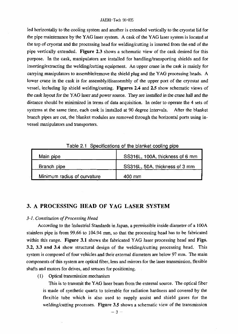
led horizontally to the cooling system and another is extended vertically to the cryostat lid for
the pipe maintenance by the YAG laser system. A cask of the YAG laser system is located at
the top of cryostat and the processing head for welding/cutting is inserted from the end of the
pipe vertically extended. Figure 2.3 shows a schematic view of the cask desired for this
purpose. In the cask, manipulators are installed for handling/transporting shields and for
inserting/extracting the welding/cutting equipment. An upper crane in the cask is mainly for
carrying manipulators to assemble/remove the shield plug and the YAG processing heads. A
lower crane in the cask is for assembly/disassembly of the upper port of the cryostat and
vessel, including lip shield welding/cutting. Figures 2.4 and 2.5 show schematic views of
the cask layout for the YAG laser and power source. They are installed in the crane hall and the
distance should be minimized in terms of data acquisition. In order to operate the 4 sets of
systems at the same time, each cask is installed at 90 degree intervals. After the blanket
branch pipes are cut, the blanket modules are removed through the horizontal ports using in-
vessel manipulators and transporters.
Table 2.1 Specifications of the blanket cooling pipe
Main pipe
Branch pipe
Minimum radius of curvature
SS316L, 100A, thickness of 6 mm
SS316L, 50A, thickness of 3 mm
400 mm
3. A PROCESSING HEAD OF YAG LASER SYSTEM
3-1. Constitution of Processing Head
According to the Industrial Standards in Japan, a permissible inside diameter of a 100A
stainless pipe is from 99.66 to 104.94 mm, so that the processing head has to be fabricated
within this range. Figure 3.1 shows the fabricated YAG laser processing head and Figs.
3.2, 3.3 and 3.4 show structural design of the welding/cutting processing head. This
system is composed of four vehicles and their external diameters are below 97 mm. The main
components of this system are optical fiber, lens and mirrors for the laser transmission, flexible
shafts and motors for drives, and sensors for positioning.
(1) Optical transmission mechanism
This is to transmit the YAG laser beam from the external source. The optical fiber
is made of synthetic quartz to tolerable for radiation hardness and covered by the
flexible tube which is also used to supply assist and shield gases for the
welding/cutting processes. Figure 3.5 shows a schematic view of the transmission
- 3 -

JAERI-Tech 96-035
tube. Total length of the optical fiber is 20 m and the core diameter is 0.6 mm. In
order to reflect and focus the laser, lens and mirror are installed in front of the fiber.
Lenses are made of synthetic quartz and mirrors are made of OFHC, which are also
chosen in terms of radiation hardness.
(2) Drive mechanism
Since accurate positioning of the processing head within the range of 0.1 mm is
required for welding by YAG laser, this system is designed to have 5-axes freedom,
which are Z, 9, R, p and L axes as shown in Fig.3.2. Due to the space constraint
and minimum curvature requirement, the system is divided into 4 vehicles and driving
mechanisms are installed in the separated vehicles(No.2 and No.3) from the power
station vehicles(No.l and No.4): These vehicles are connection links in order to
transmit the driving forces. The major specifications of the driving mechanism of each
axis are described below.
1) Zaxis
Movement direction : movement of for fine adjustment of the processing
head along the axis of the manifold
Allowable stroke : 22 mm
Movement speed : 30 mm/min
The driving power is transmitted using a flexible shaft from the power station
vehicle(No.4) to the Z axis movement mechanism composed of a ball screw.
2) 9 axis
Movement direction : rotation of the processing head around the axis of
the manifold
Rotation angle : ±185 degreeRotation speed : 3.9 rpm ( adjustable)
The 9 axis rotation mechanism is installed in the No.2 vehicle which is
connected to the processing head with the universal joint. The driving power is
transmitted from the No.l vehicle using a flexible shaft.
3) R axis
Movement direction : telescopic movement of the welding/cutting nozzle
into a branch pipe axis
Allowable stroke : 34 mm
Movement speed : 942 mm/min (adjustable)
When the nozzle is fully extended into the branch pipe, the maximum distance
from the center of the manifold to the welding/cutting point is 77 mm. On the
contrary, the minimum distance is 69 mm, as shown in Fig.3.6. As a result,
in this system, the allowable processing range is 8 mm along the branch pipe
axis. However, it can be increased up to 29 mm by modifying the R axis
telescopic mechanism.
- 4 -

JAERI-Tech 96-035
4) p axis
Movement direction : rotation of the welding/cutting nozzle around the
axis of the branch pipe
Rotation angle : ±185 degree
Rotation speed : 15 rpm (adjustable )
The driving power is transmitted from the power station vehicle(No.4).
5) Laxis
Movement direction : movement of the vehicles along the axis of the
manifold
Movement speed : 1 m/min
(3) Sensors for detecting the position of a branch pipe
Two sensors for detecting the position of a branch pipe are installed at 180 degree
intervals in the processing head. Eddy current type sensors are chosen due to its
compactness and precision. By rotating the processing head around the axis of the
manifold, the edge of a branch pipe can be detected while the head moves along the
manifold. In this way, the position of the processing head can be measured to the
branch pipe to be welded/cut. Guide rollers are installed near the sensors in order to
protect them from the corner edge of a branch pipe.
(4) Centering mechanism
Centering mechanisms based on air cylinder are installed in the No.2 and No.3
vehicles in which the processing head and the 9 axis rotating mechanism are installed.
Three air cylinders are arranged on the welding/cutting processing head and can be
contacted to the internal surface of the manifold so as to adjust the center of the head to
the manifold axis. In the case of the 0 axis rotating mechanism, three air cylinders are
also arranged in parallel to the manifold axis.
3-2. Performance Tests of Processing Head
In order to verify the basic functions and characteristics of the fabricated YAG laser
system, the processing head for welding/cutting has been tested and the results are as follows:
(1) Movement in cooling pipes
In this test, a straight pipe with length of 1000 mm and a bend pipe with a curvature
of 400 mm are prepared. They are stainless steel 316L 100A pipes with external
diameter of 114.3 mm and thickness of 6.0 mm. The processing head was repeatedly
inserted/removed into/from these pipes.
As a result, we confirmed that the processing head can smoothly move through
pipes and the required push/pull loads are only 5 kg .
(2) Driving mechanisms

JAERI-Tech 96-035
All driving mechanisms except the L-axis were tested to verify the allowable
movement stroke, rotation angle and operation speed. The results are summarized in
Table 3.1 and it is concluded that the driving mechanisms can be operated
satisfactorily and their operation ranges meet the design values.
(3) Centering mechanism
The movable strokes of the air cylinder type centering mechanisms are measured
and the operational range is confirmed to be the same as the design value, as listed in
Table 3.2.
Table 3.1 Test results of each mechanism movement
Test items
Range of
movement
Speed test
Axis of movement
0 axis
Zaxis
p axis
Raxis
9 axis
Zaxis
p axis
Raxis
Design value
±185 degree
22 mm
±185 degree
34 mm
3.9 rpm
30 mm/min
15 rpm
942 mm/min
Measurement result
Infinite rotation
21 mm
Infinite rotation
33 mm
3.91 rpm
30.0 mm/min
15.0 rpm
944.2 mm/min
Table 3.2 Test of the centering mechanism
Test items
Centering test
Cylinder
Welding/cutting
head
8 axis drive
mechanism
Design value
6 mm
8 mm
Measurement result
6 mm
8 mm
- 6 -

JAERI-Tech 96-035
4. WELDING/CUTTING CHARACTERISTICS
As mentioned above, the welding/cutting processing head by YAG laser for the blanket
maintenance has been fabricated for branch pipe welding/cutting. In parallel with this
development, welding, cutting and rewelding tests have been conducted using the industrial 2
kW YAG laser system in order to qualify the welding, cutting and rewelding conditions,
including the effect of gaps.
Figure 4.1 shows the 2 kW YAG laser welding/cutting system utilized for the tests.
This system is composed of an optical fiber with a core diameter of 0.6 mm and a length of 20
m. The focal length of the lens system is 70 mm.
4-1. Basic Welding Test
In this test, the welding conditions were surveyed using SS316L plate samples with a
thickness of 3 mm as functions of laser power, welding speed, assist gas and gaps, as listed
below. The edge preparation of the samples was machined and the surface roughness is 1.39
(i.m in average and 8.45 |i.m in peak.
Laser power : 800,1000,1200 W
Frequency : 40 Hz
Duty : 50 %
Welding speed : 500, 700, 900 mm/min
Assist gas : Nitrogen, Argon, Helium
Gap quantity : 0, 0.1, 0.2, 0.3, 0.4, 0.5 mm
Work distance : 10 mm
Defocus distance : 0 mm
4-1-1. Dependency of laser power and welding speed
The dependency of laser power and welding speed on the welding quality has been
investigated. In this test, nitrogen with a blowing rate of 0.5 1/sec was used for the assist
gas and the butt weld without gaps was adopted. The following tests were performed for
the qualification; (1) appearance test, (2) radiographic test (RT), (3) macroscopic test, (4)
tensile test.
(1) Appearance and macroscopic tests
Figure 4.2 shows the results of bead appearance test as a function of welding
speed and laser power. In the case of the laser power of 800 W, the bead penetration
to the back surface was not observed at the welding speed of 700 and 900 mm/min.
Other cases have shown full penetration welding.
(2) Radiographic test (RT)
All samples welded satisfied the RT regulation( 1 st grade) and there was no
blowhole.
- 7 -

JAERI-Tech 96-035
(3) Macroscopic test
Figure 4.3 shows the cross-section of welding penetration. It is found that
adequate welding conditions to satisfy the full penetration welding and welding
deposition are 500 mm/min at 800 W, 700 mm/min at 1000 W, and 900 mm/min at
1200 W.
(4) Tensile test
Tensile tests were carried out for all test samples welded. Figure 4.4 shows the
tensile test results. Tensile strength and elongation were remarkably decreased in case
of laser power of 800 W and welding speed of 900 mm/min due to less welding
penetration. In the case of 800 W and 700 mm/min, the elongation is decreased by
50 % composed with the base metal although the tensile strength is only 5 %
degradation.
4-1-2. Effect of assist gas
The effect of assist gas (nitrogen, argon and helium) on the weldability has been
investigated. In this test, the laser power and welding speed were fixed to be 1000 W and
700 mm/min, respectively. The following tests were performed for the qualification; (1)
appearance test, (2) radiographic test (RT), (3) macroscopic and microscopic test, (4) tensile
test.
(1) Appearance test
Figure 4.5 shows the appearance test results and all samples welded have
shown similar bead appearance.
(2) Radiographic test (RT)
In the case of helium gas, the welding quality is 2nd grade in the RT regulation.
On the other hand, the case of nitrogen and argon have shown the 1st grade in RT.
(3) Macroscopic and microscopic tests
Figure 4.6 and 4.7 show the cross-section of the welding penetration and the
micro structure, respectively. The welding deposition of all samples has similar wine-
cup type penetration although the width is slightly small in the case of helium.
(4) Tensile test
Tensile tests were carried out for all test samples welded. Table 4.1 shows the
tensile test results. Tensile strength and elongation of all samples are similar and the
elongation is decreased by around 25 % compared with the base metal.

JAERI-Tech 96-035
Table 4.1 Results of tensile tests
Assist gas
Nitrogen
Argon
Helium
Base metal
Tensile strength (MPa)
590
596587
585
Elongation (%)
40.1
40.7
38.9
54.1
4-1-3. Effect of gaps
The dependency of gaps at the edge preparation on the welding quality has been
investigated. In this test, the gaps ranging from 0 to 0.5 mm were examined under the
conditions of 1000 W laser power and 700 mm/min welding speed. The following tests of
all samples were performed for the qualification; (1) appearance test, (2) radiographic test
(RT), (3) macroscopic test, (4) tensile test.
(1) Appearance test
Figure 4.8 shows the appearance test results except the case of 0.5 mm gap
which would not be welded since the laser beam was penetrated through the gap.
Other samples have shown similar bead appearance.
(2) Radiographic test (RT)
All samples except the case of 0.5 mm gap satisfied the 1st grade in the RT
regulation and there was no blowhole.
(3) Macroscopic test
Figure 4.9 shows the cross section of welding penetration and a wine cup type
penetration was observed. In the case of 0.3 mm gap, however, the bead on the
backside is not appeared and the case of 0.4 mm gap has clearly shown the under cut
penetration.
(4) Tensile test
The tensile test results are shown in Table 4.2 and Fig. 4.10. The tensile
strength and elongation are decreased with increasing of gap. As a whole, the
maximum allowable gap for YAG laser welding without filler material is considered to
be around 0.2 mm from the tensile test results and the macroscopic tests.
- 9 -

JAERI-Tech 96-035
Table 4.2 Results of tensile tests
Gap (mm)
0.0
0.1
0.2
0.3
Base metal
Tensile strength (MPa)
590
586
560
549
585
Elongation (%)
40.1
38.3
32.1
30.4
54.1
4-1-4. Summary of welding tests
1) Optimum relation between laser power and welding speed
Table 4.3 shows the optimum relation between laser power and welding speed.
Table 4.3 Optimum relation between laser power and welding speed
Laser power (W)
800
1000
1200
Welding speed (mm/min)
500
700
900
2) Assist gas
In the case of helium gas, RT examination shows 2nd grade and welding
characteristics are inferior to other cases. In the case of nitrogen and argon, 1st grade
of RT is obtained. As a result, nitrogen gas is recommended for welding because the
number of porosity with a diameter of less 0.5 mm is few as compared with the case
of argon gas.
3) Allowable gap
A maximum allowable gap is estimated to be around 0.2 mm.
4-2. Cutting test
In this test, various of cutting conditions have been surveyed using SS316L plate
samples with a thickness of 3 mm. Cutting conditions of examined are as follows:
Laser power : 400, 600, 800 W -> Oxygen
800, 1000, 1200 W -> Nitrogen
Frequency : 40 Hz
Duty : 50 %
Cutting speed : 400, 600, 800 mm/min
- 1 0 -

JAERI-Tech 96-035
Assist gas : Nitrogen, Oxygen
Work distance : 1 mm
Defocus distance : 0 mm
4-2-1. Cutting test with the assist gas of Oxygen
The dependency of laser power, cutting speed and quantity of assist gas on the cutting
characteristics has been investigated using assist gas of oxygen. The following items were
measured for the qualification; (1) cutting surface, (2) cutting width, (3) dross and spatters,
(4) roughness of surface, (5) hardness of thermal effect part.
(1) Cutting surface
Cutting tests were carried out under various conditions of laser power and cutting
speed were changed. It is found that in the case of laser power of 400 W and cutting
speed of 800 mm/min, quantity of dross is the least Under this cutting condition, the
effect of assist gas quantity examined from 0.50, 0.83, 1.17 to 1.67 1/min. As a
result, dross is the least with assist gas of 1.67 1/min and the cutting surface is shown
in Fig. 4.11.
(2) Cutting width
Table 4.4 shows the results of cutting width under various conditions of laser
power and cutting speed with assist gas of 0.83 1/sec. All cases except the case of 800
W and 600 mm/min have shown similar difference between maximum width and
minimum width.
The dependency of assist gas quantity on the cutting width has been also examined
under the conditions of 400 W and 800 mm/min. The results are shown in Table
4.5 and both of 1.171/sec and 1.671/sec minimize the cutting width.
(3) Dross and spatters
Table 4.6 shows the results of the dross height measured under various
conditions of laser power and cutting speed with assist gas of 0.83 1/sec. In the case
of 400 W laser power and 800 mm/min cutting speed, dross height is the lowest
which is 0.43 mm. In all conditions, spatters are splashed on to the back cover plate
and the smallest in the conditions of 400 W and 800 mm/min.
As for the quantity of assist gas, the lowest dross height of 0.29 mm is obtained in
the condition of 1.67 1/sec as shown in Table 4.7.
- 1 1 -

JAERI-Tech 96-035
Table 4.4 Results of the cutting width in various conditions of
laser power and cutting speed with assist gas of Oxygen
Laser power (W)
400
600
800
Cutting speed (mm/min)
600
0.78
0.50
0.28
0.81
0.50
0.31
1.19
0.55
0.64
800
0.75
0.44
0.31
0.78
0.50
0.28
0.76
0.56
0.20
1000
0.74
0.38
0.36
0.72
0.44
0.28
0.75
0.49
0.26
Unit: mm, Upper: largest width, Middle : smallest width, Lower: difference
Table 4.5 Results of the cutting width under various quantity of assist gas
Cutting conditions
Laser power: 400 W
Cutting speed : 800 mm/min
Work distance : 1 mm
Defocus distance : 0 mm
Quantity of
0.50
0.69
0.44
0.25
0.83
0.75
0.44
0.31
assist gas
1.17
0.63
0.44
0.19
(I/sec)
1.67
0.63
0.44
0.19
Unit: mm, Upper: largest width, Middle : smallest width, Lower: difference
Table 4.6 Results of the dross height under various conditions of laser power and
cutting speed with assist gas of Oxygen
Laser power (W)
400
600
800
Cutting speed (mm/min)
600
0.55
0.77
0.86
800
0.43
0.63
0.67
1000
0.56
0.62
0.78
Unit: mm
- 1 2 -

JAERI-Tech 96-035
Table 4.7 Results of the dross height in various quantity of assist gas
Cutting conditions
Laser power: 400 W
Cutting speed : 800 mm/min
Work distance :1mm
Defocus distance : 0 mm
Quantity of assist gas (I/sec)
0.50
0.51
0.83
0.43
1.17
0.40
1.67
0.29
Unit: mm
(4) Roughness of cutting surface
Table 4.8 shows the results of roughness measurement of cutting surface under
various cutting conditions. In the case of 800 W laser power, the cutting surface
becomes coarse compared with other cases: this due to large heating energy.
Regarding with the quantity of assist, the roughness of cutting surface is not
influenced so much, as shown in Table 4.9.
(5) Hardness of cutting surface
Hardness near the cutting surface was measured and the results are shown in
Table 4.10 and Fig. 4.12. In this test, laser power of 400 W and cutting speed of
800 mm/min were fixed. As a result, the hardness becomes the same as the base metal
at least 1 mm distance from the centering surface.
Table 4.8 Results of the roughness measurement of cutting surface under various
conditions of laser power and cutting speed with assist gas of Oxygen
Laser power (W)
400
600
800
Cutting speed (mm/min)
600
10.8
75.9
9.3
62.4
16.7
113.0
800
13.3
98.8
11.9
90.1
14.5
114.1
1000
13.6
87.5
13.3
95.7
15.6
119.9
Unit: urn, Upper: Ra, Lower: Rmax
- 1 3 -

JAERI-Tech 96-035
Table 4.9 Results of the roughness of cutting surface
in various quantity of assist gas
Cutting conditions
Laser power: 400 W
Cutting speed : 800 mm/min
Work distance :1mm
Defocus distance : 0 mm
Quantity of assist gas (I/sec)
0.50
11.1
81.5
0.83
13.3
98.8
1.17
12.8
84.2
1.67
11.9
81.5
Unit: |i.m, Upper: Ra, Lower: Rmax
Table 4.10 Results of the hardness test
Cutting conditions
Laser power: 400 W
Cutting speed : 800 mm/min
Work distance : 1 mm
Defocus distance : 0 mm
Distance fromcutting surface
(mm)
0.1
0.2
0.4
0.6
0.81.0
2.0
3.0
Hardness (Hv)
206
185
179152
158
149144
152
Hardness of base metal : 150 (Hv)
4-2-2. Cutting test with the assist gas of Nitrogen
The cutting characteristics are also investigated in the case of nitrogen assist gas. As a
function of laser power, cutting speed and quantity of assist gas. The following
measurements were performed for the qualification; (1) cutting surface, (2) cutting width,
(3) dross and spatters, (4) roughness of surface, (5) hardness of near the cutting surface.
(1) Cutting surface
Cutting tests were carried out under various laser power and cutting speed
conditions. In the case of laser power of 1000 W and cutting speed of 800 mm/min,
relatively good cutting surface was observed. On the other hand, cutting was
impossible in the case of laser power of 800 W and cutting speed of 800 mm/min.
The quantity of assist gas was varied from 1.25 to 1.67 1/min under the conditions of
- 1 4 -

JAERI-Tech 96-035
1000 W and 800 mm/min. As a result, quantity of dross is the least with assist gas of
1.671/min and the cross-sectional view of the cutting surface is shown in Fig. 4.13.
(2) Cutting width
Table 4.11 shows the results of the cutting width under various conditions of
laser power and cutting speed with assist gas of 1.67 1/sec. All results have shown
similar cutting width and the case of 1200 W and 800 mm/min indicates the minimum
width.
In addition, the cutting width is not significantly influenced by changing of assist
gas quantity, as shown in Table 4.12.
Table 4.11 Results of the measured cutting width under various conditions of
laser power and cutting speed with assist gas of Nitrogen
Laser power (W)
800
1000
1200
400
0.75
0.47
0.28
0.75
0.50
0.25
0.69
0.47
0.22
Cutting speed (mm/min)
600
0.75
0.50
0.25
0.69
0.49
0.20
0.72
0.43
0.29
800
-
-
0.66
0.43
0.23
0.66
0.50
0.16
Unit: mm, Upper: largest width, Middle : smallest width, Lower: difference
Table 4.12 Results of the measured cutting width in various quantity of assist gas
Cutting conditions
Laser power: 1000 W
Cutting speed : 800 mm/min
Work distance : 1 mm
Defocus distance : 0 mm
Quantity of assist gas (I/sec)
1.25
0.63
0.44
0.19
1.67
0.66
0.43
0.23
Unit: mm, Upper: largest width, Middle : smallest width, Lower: difference
(3) Dross and spatters
- 1 5 -

JAERI-Tech 96-035
Table 4.13 shows the results of the dross height measured under the various
conditions of laser power and cutting speed with assist gas of 1.671/sec. In the case
of 1000 W laser power and 800 mm/min cutting speed, dross height is the lowest
which is 2.29 mm. In all conditions, spatters were splashed on to the back cover
plate, and the quantity of spatter was smallest in the condition of 1000 W and 800
mm/min.
Regarding with the quantity of assist gas, similar dross height was observed in
both conditions of 1.25 1/sec and 1.67 1/sec, as shown in Table 4.14.
Table 4.13 Results of the dross height under the various conditions of laser power
and cutting speed with assist gas of Nitrogen
Laser power (W)
800
1000
1200
Cutting speed (mm/min)
400
2.46
2.39
2.34
600
2.73
2.81
2.71
800
-
2.29
2.37
Unit: mm
Table 4.14 Results of the dross height in various quantity of assist gas
Cutting conditions
Laser power: 1000 W
Cutting speed : 800 mm/min
Work distance : 1 mm
Defocus distance : 0 mm
Quantity of assist gas (I/sec)
1.25
2.17
1.67
2.29
Unit: mm
(4) Roughness of cutting surface
Table 4.15 shows the measured roughness of cutting surface under the various
conditions of laser power and cutting speed. In the case of 1000 W laser power,
cutting surface was relatively smoother compared with others.
Table 4.16 shows the effect of assist gas quantity on the surface roughness and
the roughness is slightly increased with increasing the flow rate.
(5) Hardness of near the cutting surface
- 1 6 -

JAERI-Tech 96-035
Hardness near the cutting surface was measured and the results are shown in
Table 4.17 and Fig. 4.14. As the result, it is found that hardening due to the laser
cutting reaches to 1 mm depth from the cutting surface.
Table 4.15 Results of the measured roughness of cutting surface under various
conditions of laser power and cutting speed with assist gas of Nitrogen
Laser power (W)
800
1000
1200
Cutting speed (mm/min)
400
10.9
91.0
6.9
48.9
11.6
104.5
600
9.2
66.7
7.4
48.9
10.1
77.8
800
-
8.7
61.6
8.2
48.3
Unit: |im, Upper: Ra, Lower: Rmax
Table 4.16 Results of the measured roughness of cutting surface
under various quantity of assist gas
Cutting conditions
Laser power: 1000 W
Cutting speed : 800 mm/min
Work distance : 1 mm
Defocus distance : 0 mm
Quantity of assist gas (I/sec)
1.25
5.5
55.6
1.67
8.7
61.6
Unit: jxm, Upper: Ra, Lower: Rmax
- 1 7 -

JAERI-Tech 96-035
Table 4.17 Results of the hardness test
Cutting conditions
Laser power: 1000 W
Cutting speed : 800 mm/mtn
Work distance :1mm
Defocus distance : 0 mm
Distance fromcutting surface
(mm)
0.1
0.2
0.4
0.6
0.8
1.0
2.0
3.0
Hardness (Hv)
203
200
180
169
161152
150
150
Hardness of base metal: 150 (Hv)
4-2-3. Summary of cutting tests
From these test results mentioned above, the following cutting conditions should be
adopted:
1) Assist gas with oxygen
Laser power
Cutting speed
Quantity of assist gas
400 W
800mm/min
1.671/sec
2) Assist gas with nitrogen
Laser power
Cutting speed
Quantity of assist gas
1000 W
800mm/min
1.671/sec
Following rewelding tests mentioned below were carried out using these samples.
4-3. Rewelding test
To verify the reweldability of the laser cutting surface, rewelding tests were performed
under the following conditions. In this test, the laser cutting samples with assist gas of oxygen
and nitrogen were welded to SS316L plates with machining surface. The surface roughness of
the laser cutting samples were measured prior to the rewelding test and the results are presented
in Table 4.18. After the rewelding tests, bead appearance, X-ray inspection, microscopic
structures and tensile properties were measured for the welding qualification:
- 1 8 -

JAERI-Tech 96-035
:1OOOW
:40Hz
:5O%
: 700 mm/min
: Nitrogen, 0.5 1/sec
: 1 mm
: 0mm
Laser power
Frequency
Duty
Rewelding speed
Assist gas
Work distance
Defocus distance
(1) Appearance test
Figure 4.15 shows the bead appearance after the rewelding. Both samples cut
by oxygen assisted laser and nitrogen assisted laser have shown similar bead
appearance.
(2) Radiographic test (RT)
Both samples have shown the 1st grade in the RT regulation.
(3) Macroscopic and microscopic test
Figure 4.16 shows the cross-section of welding penetration. In both samples, a
wine cup type penetration was obtained and the nitrogen assisted laser cutting sample
indicates, a wide welding penetration compared with the oxygen assisted laser cutting
sample.
Microscopic structures of the welding joints are similar in both samples and
dendrite structures are observed, as shown in Fig.4.17.
(4) Tensile test
Tensile tests were carried out for both samples after rewelding. Table 4.19
shows the tensile test results and tensile strength and elongation of oxygen assisted
laser cutting samples are lower than those of nitrogen assisted laser cutting sample.
Table 4.18 Cutting surface of test pieces
Cutting conditions
Machining
Laser cutting with Oxygen
Laser power: 400 W
Cutting speed : 800 mm/min
Quantity of gas : 0.83 I/sec
Laser cutting with Nitrogen
Laser power: 1000 W
Cutting speed : 800 mm/min
Quantity of gas : 1.67 I/sec
Ra (urn)
1.39
13.3
8.67
Rmax (urn)
8.45
98.8
61.6
-19

JAERI-Tech 96-035
In this table, the tensile test results of a standard sample with machining surface are
presented as a reference case. Comparing with this reference case, the mechanical properties of
both laser cutting samples are slightly decreased but their degradation seems to be within the
allowable range. As a whole, rewelding of the laser cutting samples can be possible.
Table 4.19 Results of tensile tests
Combination
Machining
+ Machining
Machining
+ Oxygen cutting
Machining
+ Nitrogen cutting
Test
No.
1
2
3
Ave.
1
2
3
Ave.
1
2
3
Ave.
Tensile strength
(MPa)
590
593
588
590
578
579
575
577
587
589
586
587
Elongation (%)
40.7
40.4
39.6
40.1
31.2
30.8
29.2
30.4
39.6
37.2
37.2
38.0
RT level
1st
1st
1st
5. CONCLUSION
A YAG laser type processing head has been successfully fabricated and the applicability
to the blanket branch pipe welding/cutting has been demonstrated. In particular, this system
can be moved inside a 100-A pipe with a minimum curvature of 400 mm and the
welding/cutting nozzle with telescopic mechanism can be extended into a branch pipe with a
diameter of 50 mm for welding/cutting. In addition, this system is designed to have 5 axes
freedom so as to position the welding/cutting nozzle within the required accuracy for
welding/cutting. The centering mechanisms and position sensors are also facilitated for
positioning and fixation of the processing head. In parallel with this tool development,
welding/cutting/rewelding experiments using YAG laser have been performed to clarify the
optimum welding and cutting conditions including the effects of gaps and assist gas on the
weldability and reweldability. From these tests, the following conclusions are obtained:
- 2 0 -

JAERI-Tech 96-035
1) The optimum conditions of welding speed and laser power are 500 mm/rnin for 800
W, 700 mm/min for 1000 W and 900 mm/min for 1200 W.
2) A maximum allowable gap for welding is to be around 0.2 mm without filler
materials.
3) The optimum cutting conditions are 400 W / 800 mm/min in the case of oxygen
assisted cutting and 1000 W / 800 mm/min for nitrogen assisted cutting.
4) Rewelding of the laser cutting surface can be performed with keeping similar
mechanical properties to those of machining surface.
As the next development step, the following items are to be addressed:
1) Mock-up tests of the YAG laser processing head to demonstrate the total system
performance under the real pipe layout.
2) Possibility to increase the laser power for thick plate welding/cutting.
3) Establishment of rescue procedures.
4) Development of weld inspection and leak detection systems.
ACKNOWLEDGMENTS
The authors would like to express their sincere appreciation to Drs. M. Ohta, S. Matsuda,
M. Seki and S. Shimamoto for their continuous encouragement on this work. The
contributions by the staffs of department of ITER project and Toshiba Corp., are gratefully
acknowledged.
REFERENCES
[1] S.Matsuda, et al: Proc. 13th Conf. on Plasma Physics and Controlled Nuclear Fusion
Research, (Washington, 1990) IAEA-CN-53/G-2-2.
[2] K.Shibanuma, T.Honda, K.Satoh, Y.Ohkawa, T.Terakado, et al: Remote Maintenance
System Design and Component Development for Fusion Experimental Reactor, Proc. 16th
Sympo. on Fusion Tech., Vol.2, pp.l317-1321(1990)
[3] K.Honda, Y.Makino, M.Kondoh, K.Shibanuma: Feasibility Study of Internal-Access Pipe
Welding/Cutting System for Fusion Experimental Reactor(FER), Proc.LASER'91,(1991)
[4] K.Oka, S.Kakudate, M.Nakahira, et al: Critical Element Development of Standard
Components for Pipe Welding/Cutting by CO2 laser, JAERI Tech 94-033 (1994)
[5] M.Nakahira, K.Oka, S.Kakudate, , et al: Feasibility Study on YAG Laser System for
Cooling Pipe Maintenance, FTER Emergency Task Agreement JB-RH-1 (1993)
- 2 1 -

8000
ItoCO
I
Guide roller &Centerins mechanism
Power station(& Travel ins vehicle) /
Flexibleshaft
i
3
DetalI A
Fig. 1.1 Schematic view of the blanket maintenance Fig. 2.1 Schematic view of approachingthe blanket module

The insertion pipe for a processing head
I
Manipulator forcarr1ns shlelds
Manipulator for oarrlnswelding/cutting tools
LIP seal machine
Double-sealed door
Shi a Id Plug
>MSOi—<I
ft
CT51o
Fig. 2.2 Schematic view of the upper blanket pipe Fig. 2.3 A cask for the welding/cutting processing equipment

Laser andPower sour
DO
The caskithe b
forket Pi Pe
maintenancenap
Fig. 2.4 Cask layout for the blanket pipe maintenance(cross section)
Jhe cask for=^ the branket PiP-e
mai ntenance
2
2COOn
Fig. 2.5 Cask layout for the blanket pipe maintenance(top of view)

JAERI-Tech 96-035
CO
<
•8CD
CD
0.9-COCO0ooCtf
CD
0
CO
d
- 2 5 -

Movement range
R
Z
P
e
axis
axis
axis
axis
stroke
stroke
rotation
rotation
: 35 mm
:22 mm
:±185°
:±185°
No.1 vehicle
I082
Connection link
/ Centering mechanism
paxis No.4 vehicle
, ^ Branch pipe Main pipe
9 axis motor No.2 vehicle 9 axis z a x j s N o 3 v e n i c l e
Flexibleshaft
Universal Joint(processing head)
FlexibleR, Z, p axes motor
>2
i
o
Fig. 3.2 Schematic of YAG laser processing head

2nd Cu mirror
Sensorp axis
Nozzle
axis
Connection link
Centering e a x i s b e a r i n 9 Centering
mechanism j Optical fiber
\ „ p axis rotatingp axis mechanismbearing
Main pipe
0 axis rotatingmechanism
Flexible shaft Flexible shaft
1 st Cu mirror
0 axis drivenvehicle
Processinghead
io
Fig. 3.3 Inside structure of YAG laser processing head

>en2
T
ig. 3.4 Schematic of passing through a bending pipe (R400)

A
0°V
oOLO
-©-
AAssist gas
Optical fiber
A-A
sI
Ho
o
Transmission tube
Fig. 3.5 Schematic view of the transmission tube

JAERI-Tech 96-035
Noz
Main PIPe
Welding/cutting head
Iranch PIPe
Aval I able rangeof Processing
O)CO
N
Fig. 3.6 Available range of welding/cutting processing
-30

JAERI-Tech 96-035
(a) 2 kW YAG laser source
(b) Processing equipment
(c) Processing6 Heads
ooa=FOscillator
Focusing lens unit'Fiber
Df
(d) Schematic diagram of equipment
Fig. 4.1 YAG laser processing equipmentfor basic performance test
- 3 1

JAERI-Tech 96-035
Laserpower (W)
1000
1200
Welding speed (mm/min)
Laser surface
Back surface
Laser surface
Back surface
Laser surface
Back surface
Laser surface
Back surface
Laser surface
Back surface
Laser surface
Back surface
Fig. 4.2 Result of bead appearance testTest conditions
Test pieces
FrequencyDutyAssist gasWork distanceGap
:SS316L flat plate,thickness of 3 mm
: 40 Hz: 50 %: Nitrogen, 0.5 I/sec: 10 mm:0 mm
- 3 2 -

Laser power (W)
800
COoo
1000
1200
Welding speed (mm/min)
500
.-fCH
* « W . ~-
700 900
>tnVH
iOOen
Fig. 4.3 Macroscopic observation of weld part

105
0Q.
2Q.
95
90COo'c03
I 850
10
80
75
o 500 mm/min
- - • - - 7 0 0 mm/min
— a - - 900 mm/min
Normarized by virgin materialTensile strength : 585 MPa
800 1000Power (W)
Tensile strength
0
O
O"cCO
o
90
80
70
60
50
0 40
1 30* 20
Normarized by virgin materia!f Elongation : 54.1 %
500 mm/min
»»#»-7Q0 mm/min
-900 mm/min
800 1000 1200Power (W)
Elongation
Fig. 4.4 The relation between laser power and welding speedTest conditions
Test pieces : SS316L flat plate, thickness of 3 mmFrequency & duty : 40 Hz, 50 %Assist gas : Nitrogen, 0.5 I/secWork distance : 10 mmGap : 0 mm (butt welding)
m2!
nn

Assist gas (1/sec)
Nitrogen Argon Helium
0.50 0.50 0.83
CJ1
Laser surface Laser surface Laser surface
Back surface Back surface Back surface
Fig. 4.5 Result of bead appearance test with different assist gasTest conditions
: SS316L flat plate, thickness of 3 mmTest piecesLaser powerWelding speedFrequencyDutyWork distanceGap
1000W700 mm/min40 Hz50%10 mm0 mm
73
oen

Laser welding conditions
Assist gas (I/sec)
ICO
Laser power : 1000 W
Frequency : 40 Hz
Duty :50%
Welding speed : 700 mm/min
Work distance : 10 mm
Gap : 0 mm
Defocus distance : 0 mm
Welding joint : butt
>en2
i
oen
Fig. 4.6 Macroscopic observation of welding testwith different assist gas

Laser welding conditions Nitrogen , 0.50Assist gas (I/sec)
Argon , 0.50 Helium , 0.83
Ico
Laser weld part
Weid part Boundary part(Lower fig.) (Upper fig.)
Laser power : 1000W
Frequency : 40 Hz
Duty : 50 %
Welding speed : 700 mm/min
Work distance : 10 mm
Defocus distance : 0 mm
Welding joint : butt
Gap : 0 mm
v j ' " '
'I*r^l>* -V^vw^rfw
0 s f f p
Nitrogen, 0.50 Argon ,0.5 ,0.83
„- ''if ^
' ' v t ' * * , * * * • { * , '
^ . ^ 2 "«. ! v t
i
sOn
Fig. 4.7 Microscopic observation of welding test with different assist gas

Laser welding conditions 0Gap (mm)
0.1 0.2
00I
Laser power : 1000W
Frequency : 40 Hz
Duty : 50 %
Welding speed : 700 mm/min
Assist gas : Nitrogen, 0.5 I/sec ;
Work distance : 10 mm
Defocus distance : 0 mm
Welding joint : butt
Gap : 0 mm
.aser surface
Back surface
0.3
Laser surface
Back surface
t aser surface
Back surface
0.4
Back surface
Laser surface
Back surface
0.5
laser surface
Back surface
>mPC
i
Hn
ooen
Fig. 4.8 Result of bead appearance test with different gap

Laser welding conditions 0
Gap (mm)
0.1 0.2
i
Laser power : 1000W
Frequency : 40 Hz
Duty : 50 %
Welding speed : 700 mm/min
Assist gas : Nitrogen, 0.5 !/sec
Work distance : 10 mm
Defocus distance : 0 mm
Welding joint : butt
rr>
0.3 0.4 0.5
impossible
sI
re
!COon
Fig. 4.9 Macroscopic observation of gap test

JAERI-Tech 96-035
0Q,O
CO
oCO
o
0
J5CD
110
100
90
80
70
60
50
n
i >,
Normali' TensileElongai
4s
|
zed by vstrengthion
L J
r~ i
5t
I ~-1
o Tensile strengtm Elongation (%)
(
rgin mat: 585 MF: 54.1 %
srial>a 1t
)
h(%)
- .
0 0.1 0.2Gap (mm)
0.3
Fig. 4.10 Result of allowable gap testTest conditions
Test pieces
Laser powerWelding speedFrequencyDutyAssist gasWork distance
SS316L flat plate,thickness of 3 mm1000 W700 mm/min40 Hz50%Nitrogen, 0.5 I/sec10 mm
- 4 0 -

JAERI-Tech 96-035
^
40 h n 6G ''--I 8G n K H Sfi 70
a) Laser surface b) Back surfaceA) Cutting appearance
4.0 S O 60 70 80
B) Cross sectionyssyyyyJ*yMryjMy4a<*yyZyZ&
Cuttina conditionsLaser powerCutting speedFrequencyDutyAssist gas
Work distance
:400W: 800 mm/min:40Hz: 50 %
1.67 I/sec ^^^^S^m,: 1 mm I l l l l l l l
90 *
rn m
Defocus distance : 0 mm C) Cutting width
Fig. 4.11 Cutting surface with assist gas of Oxygen
- 4 1

JAERI-Tech 96-035
C/3
0C
05
210
200
190
180
170
160
150
. » . • • , - . . - , . . .y -p .y .
# Weld part
Base metai
•\ A C \ F . L . I . . . J • i i . . . ; . . . • f I i • ' • * i i . ' < \ > , ? t, > J ..••' J L i • * . i A i i
0 0.5 1 1.5 2 2.5 3 3.Distance from cutting surface (mm)
Fig. 4.12 Result of hardness teston Oxygen cutting surfaceTest conditions
:SS316L flat plate,thickness of 3 mm
est dTest pieces
Laser powerCutting speedFrequencyDutyAssist gas
400 W800 mm/min40 Hz
: 50 %: Oxygen, 1.67 I/sec
Work distance : 1 mm
- 4 2 -

JAERI-Tech 96-035
M
i n n M^ !2° |; so i n n no 12c 130
a) Laser surface b) Back surfaceA) Cutting appearance
|lh'|J
Cuttina conditionsLaser power :Cutting speed :Frequency :Duty :Assist gas :
Work distance :Defocus distance
i j-':i \ - ]" * \-v \ P I I j i i i f H H i r n iinjiing0 ?o hu ^o 11 i l l
B) Cross section
1000 W ?*-? r
800 mm/min40 Hz jkjM50 % •Nitrogen, ^ - . JB ^ ^1.67 I/sec ^^^^•L ] ^ H | |1 mm ^H^^^^^^rt^^^M^^BBB!: 0 mm C) Cutting width
mm
Fig. 4.13 Cutting surface with assist gas of Nitrogen
- 4 3

JAERI-Tech 96-035
CO(/)
210
200 -
190 -
180 -
170 -
160 -
150
140
,.Sf,w
_ A..~ w
"M
m
• • • .
*
. . . .
, . , ,
# Weld part
— Base metal
, . , . r • > } i 1 1 1 1
-
0 0.5 1 1.5 2 2.5 3 3.5
Distance from cutting surface (mm)
. 4.14 Result of hardness teston Nitrogen cutting surface
Test conditionsTest pieces
Laser powerCutting speedFrequencyDutyAssist gasWork distance
: SS316L flat plate,thickness of 3 mm
:1000W: 800 mm/min:40Hz: 50 %: Nitrogen, 1.67 I/sec: 1 mm
- 44

JAERI-Tech 96-035
Oxygen cutti
Laser
3
Back
Combination
n^L+jTiachming_^
surface
• r
surface
Nitrogen cutting + machining
Laser surface
s
s
Back surface
Fig. 4.15 Result of bead appearance testof rewelding
Test conditionsTest pieces
Laser powerWelding speedFrequencyDutyAssist gasWork distance
:SS316L flat plate,thickness of 3 mm
:1000W: 700 mm/min:40Hz: 50 %: Nitrogen, 0.5 I/sec: 10 mm
- 4 5 -

IOS
Laser welding conditions
Laser power : 1000 WFrequency :40 HzDuty : 50 %Welding speed : 700 mm/minAssist gas : Nitrogen, 0.5 I/secWork distance :10mmDefocus distance : 0 mmWelding joint : buttGap :0 mm
CombinationN2 cutting + machining O2 cutting + machining
>
o0-1
Fig. 4.16 Macroscopic observation of rewelding test

I
Laser cutting conditions
Laser weld part
\Weid part Boundary part
(Lower fig.) (Upper fig.)
Laser power : 1000 W
Frequency : 40 Hz
Duty : 50 %
Welding speed : 700 mm/min
Work distance : 10 mm
Gap : 0 mm
Defocus distance : 0 mm
Welding joint : butt
Combination
Oxygen cutting + machining
Oxygen cutting + machining
Nitrogen cutting + macnining
Nitrogen cutting + macnining
i
ft
Son
Fig. 4.17 Microscopic observation of reweiding test

*
ftH
*
W))t
4
1
K
4i
S U
M
Ra
iff
sfg
ftft
> -
r y
*
3̂ y
7 y
X -r y
fth
»' 7
t
r
IV
A
T
y
7
y
y
i"d •}
m
kgs
A
K
mol
cd
rad
sr
S 3
fS]
Hi )
i. i<. iv
I " . ••%
* aiBM.
itl
p y
IB
«-f y-t ^
)t
1
M
f]
it-
. () :*.»
a
*7• y
M
Hi. fea
ft7 7 y
* ;
7 7 y0 X &
W
"'i
a
/;
*fitt)1f/i
X
*
X
ff
*
ft
tt
—'<•y
7
7
+:7
• y
•?
T
' S
-b
^
9
•y
?i ft
IV
i - h
x yj
i -
y
— D
;u
T 7
-
i -
X
y ')
- >
9
- ^ ' • " -
"V
y
/u
1-
y
I-
KA
X
'<
7
-
fty
X
h
? 1 1 1nL ' j
Hz
N
Pa
J
W
cV
F
ns
Wb
T
H
°Clm
Ix
Bq
Gy
Sv
ftt© SI ¥.{»>It X -5 R «
s
m-kg/s'N/m-'N-m
J / s
A-s
W/A
C/V
V/A
A/V
V-s
Wb/m'Wb/A
cd-srIm/m2
s"1
J/kgJ/kg
uh
M
2
•
f
Sl<!
11
y
id H-
min, h.
1. L
t
eV
u
/
d
1 eV = 1.60218 x 1 0 " J
1 u - 1.66054x10" kg
* y 7 x h
/<
if
¥ a
u y t-
7
ly
ftD —
y
A
y
-
y
K
A
Id vA
b
bar
Gal
Ci
R
rad
r e m
1 A- 0.1 nm = 10"'°m
1 b=100fm!=10-!"m2
1 bar=0.1 MPa-10'Pa
1 Gal^l cm/s^ lO- 'm/
1 Ci = 3.7x]0'"Bq
1 R=2.58xl0'C/kg
1 rad = lcGy=10 !Gy
1 rem= 1 cSv = 10 * Sv
tea1 0 "
1 0 "
1O!!
10'
10'
10'
102
10'
10"'
10 '
10" =
1 0 '
io- '
10 1!
10""
10""
fiX
"<
-f
¥
¥
T
T
-b
t '
T
IBI.'S
•? "t
7
fi
fia
9 h
•y
y -f
U
/
x A h
r
Id S}
Ep
T
GM
k
h
da
d
c
m
u
n
Pf
a
(it.)
l, M\ 5 l i i&j 355RS. MR/:^L, 1 eV
1 u » « l i CODATA CD 19865f-«<g
2.
- 'I* t> ft4 f i t l > 5AM 1 ftmip.<,'/.'ii^)"c C
3. b a r l i .
•So
r Ifnfi:
£;mfirT(ibar. barnfcj:'/. 1 mmHg t h 2 01 fi f 3 'J
h
9
4
10'dyn)
1
80665
44822
0
0
kgf
101972
1
453592
Ibf
0.224809
2.20462
1
V; ft 1 Pa-s(N-s/mM= lOPf * T x-)(g/(cm-s)J
ftttff 1 mVs- lO 'SK ?- V - 7 X McrnVs)
/J
MPa!--10bar)
1
0.0980665
0,101325
1.33322 x 10"'
6.89476 x 10"'
kgf/cm'
10.1972
1
1.03323
1.35951 x 10 3
7.03070 x 10 '
a tm
9.86923
0.967841
1
1.31579 x 10"'
6.80460 x 10 '
mmHglTorr )
7.50062 x 10'
73S.559
760
1
51.7149
lbf/in'(psi>
145.038
14.2233
14,6959
1.93368 x 10 '
1
X
IV
¥1
It,•a
J( =10 'e rg )
1
9.80665
3.6 x 10*
4.18605
1055.06
1,35582
1 60218 x 10 "
kgf-m
0.101972
1
3.67098 x 10 s
0.426858
107,586
0.138255
1.63377 x 10 i0
kW- h
2.77778 x 10- !
2.72407 x 10"'
1
1.16279 x 10-'
2.93072 x 10"'
3,76616 x 10 ;
4,45050 x 10 "
calUtltt)
0.238889
2.34270
8.59999 x 10 s
1
252.042
0.323890
3.82743 x 10 •"»
Btu
9.47813 x 10 '
9.29487 x 1 0 '
3412.13
3.96759 x 10 '
1
1.28506 x 10" '
1.51857 x 10 "
ft • lbf
0.737562
7.23301
2.65522 x 10⁶
3.08747
778.172
1
1.18171 x 10""
eV
6.24150 x 10"
6.12082x 10"
2.24694 x 10"
2.61272x 10"
6.58515 x 10-"
846233 x 1 0 "
1
»t
3 7
Bq
1
X 101"
Ci
2.70270 x
1
1 0 "
Gy
1
001
rad
100
1
C/kg
2.58 x 10"4
_ R
3876
1
1 cal - 4.18605 J( , , l W/J;
= 4.184 J ( » f f r "
4.1855 J (15 X '
^ 1 PS < iLfij )) i
- 75 kgf-m/s
-- 735.499 W
ISlit''iw
Sv
1
001
rem
100
1
<86tr 12 n 26

DEVEIOPIIENT OF iEyOTE BORE TOOiS FOR PIPE WELDIiG/CUTTWG BY YAG LASER


![035[Manual] Nissan Tsuru 91-96 - Serie B13 Motor GA16DNE (Suplemento) - Embrague](https://img.pdfslide.net/doc/110x75/577cde541a28ab9e78aeea24/035manual-nissan-tsuru-91-96-serie-b13-motor-ga16dne-suplemento-embrague.jpg)