Embed Size (px)
Citation preview
Jaguar Motor Controller
Getting Started Guide
1212
Jaguar Motor Controller Getting Started Guide 2
Jaguar Motor Controller Getting Started Guide
Table of ContentsChapter 1: Introduction to Jaguar .....................................................................................................................3
Features ............................................................................................................................................................5Warnings ............................................................................................................................................................6
Chapter 2: General Operation ...........................................................................................................................7Operating Modes ................................................................................................................................................8
Fault Conditions ..............................................................................................................................................8Coast/Brake Jumper .......................................................................................................................................9Power and Motor Wiring .................................................................................................................................9Automatic Ramp Mode ...................................................................................................................................9
Chapter 3: Servo/PWM-based Control ............................................................................................................11Servo-Style PWM Speed Control Input ............................................................................................................11
Calibrating the PWM Input ............................................................................................................................11Chapter 4: Introduction to Network-Based Control ......................................................................................13
Network Security and System Safety ...............................................................................................................13Trusted Mode (FIRST Robotics Competition feature) ......................................................................................13
Chapter 5: Operation using the RS232 Interface ...........................................................................................14BDC-COMM Application Overview ...................................................................................................................14
Chapter 6: Firmware Update Using BDC-COMM ...........................................................................................16Important Information .......................................................................................................................................16
Step 1: Hardware Setup ................................................................................................................................16Step 2: Run BDC-COMM ..............................................................................................................................17Step 3: Assign Unique CAN ID .....................................................................................................................17Step 4: Update Firmware ..............................................................................................................................17
Chapter 7: Closed-Loop Control Options ......................................................................................................18Wiring ...............................................................................................................................................................18Constant Current Control .................................................................................................................................19Position Control using an Encoder ...................................................................................................................19Position Control Using a Potentiometer ...........................................................................................................20Speed Control ..................................................................................................................................................20
Chapter 8: Operation Using the CAN Interface ..............................................................................................21CAN IDs ...........................................................................................................................................................21CAN Network ...................................................................................................................................................21Control Options for Networked Jaguar Modules ..............................................................................................22
Appendix A: Jaguar Communication Cables .................................................................................................23CAN Terminator ................................................................................................................................................23CAN Cable .......................................................................................................................................................23
CAN Cable Assembly ....................................................................................................................................24CAN Cable Pin Assignments ........................................................................................................................24RS232 Cable .................................................................................................................................................24RS232 Cable Assembly ................................................................................................................................25
External References .........................................................................................................................................25
Jaguar Motor Controller Getting Started Guide 3
Jaguar Motor Controller Getting Started Guide
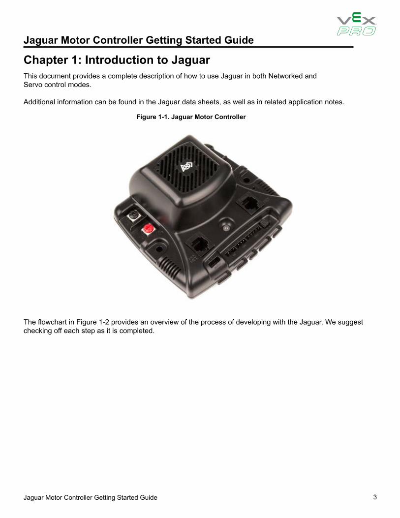
Figure 1-1. Jaguar Motor Controller
Chapter 1: Introduction to JaguarThis document provides a complete description of how to use Jaguar in both Networked and Servo control modes.
Additional information can be found in the Jaguar data sheets, as well as in related application notes.
The flowchart in Figure 1-2 provides an overview of the process of developing with the Jaguar. We suggest checking off each step as it is completed.

Jaguar Motor Controller Getting Started Guide 4
Jaguar Motor Controller Getting Started GuideFigure 1-2. Jaguar Development Process
Getting Started with Jaguar
Connect:- Servo cable- Power cable- Motor cable
Decision:Control using
Servo/PWM or Network?
Read Jaguar GSG Introduction and
General Operation Chapters
Servo/PWM
Read Jaguar GSG Servo/PWM
ControlChapter
Ready to Run!
Read Jaguar GSG Introduction to
Network Control Chapter
Decision:CAN Interface
Method
Network
Read 3rd Party CAN Bridge
documentation
3rd Party CAN Interface
Assemble and connect cables:- RS232/CAN
- Power
Read Jaguar GSG Operation using RS232 Chapter
Read Jaguar GSG Firmware Update using BDC-COMM
Chapter
Update firmware in each Jaguar
Connect to cRIO-based FRC control
system
Black Jaguar Bridge
Read Jaguar GSG Operation using
the CAN InterfaceChapterAppendix A
Jaguar Cable Assemblies
Assign CAN ID(ID Value > 1)
Jaguar Motor Controller Getting Started Guide 5
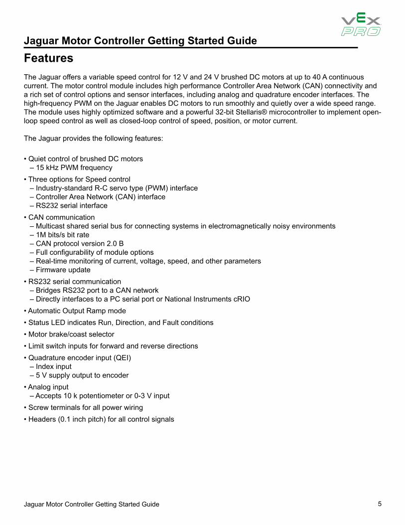
Jaguar Motor Controller Getting Started GuideFeatures The Jaguar offers a variable speed control for 12 V and 24 V brushed DC motors at up to 40 A continuous current. The motor control module includes high performance Controller Area Network (CAN) connectivity and a rich set of control options and sensor interfaces, including analog and quadrature encoder interfaces. The high-frequency PWM on the Jaguar enables DC motors to run smoothly and quietly over a wide speed range. The module uses highly optimized software and a powerful 32-bit Stellaris® microcontroller to implement open-loop speed control as well as closed-loop control of speed, position, or motor current.
The Jaguar provides the following features:
• Quiet control of brushed DC motors– 15 kHz PWM frequency
• Three options for Speed control– Industry-standard R-C servo type (PWM) interface– Controller Area Network (CAN) interface– RS232 serial interface
• CAN communication– Multicast shared serial bus for connecting systems in electromagnetically noisy environments– 1M bits/s bit rate– CAN protocol version 2.0 B– Full configurability of module options– Real-time monitoring of current, voltage, speed, and other parameters– Firmware update
• RS232 serial communication– Bridges RS232 port to a CAN network– Directly interfaces to a PC serial port or National Instruments cRIO
• Automatic Output Ramp mode• Status LED indicates Run, Direction, and Fault conditions• Motor brake/coast selector• Limit switch inputs for forward and reverse directions• Quadrature encoder input (QEI)
– Index input– 5 V supply output to encoder
• Analog input– Accepts 10 k potentiometer or 0-3 V input
• Screw terminals for all power wiring• Headers (0.1 inch pitch) for all control signals
Jaguar Motor Controller Getting Started Guide 6
Jaguar Motor Controller Getting Started Guide
WARNING – Be aware of the following warnings. Failure to heed warnings can result in damage to the module or invalidation of the module warranty.
Warnings
• Mount the Jaguar module so that the vents in the top and sides of the unit are not restricted in any way. Maintain a clearance of at least ½ inch between modules.
• Reverse wiring is unprotected; doing so voids the Jaguar module’s warranty. Do not exceed the absolute maximum supply voltage (30 VDC)
• Doing so causes permanent damage to the module.• Protect Jaguar from all situations where debris could enter through ventilation slots or connector openings.
Jaguar Motor Controller Getting Started Guide 7
Jaguar Motor Controller Getting Started Guide
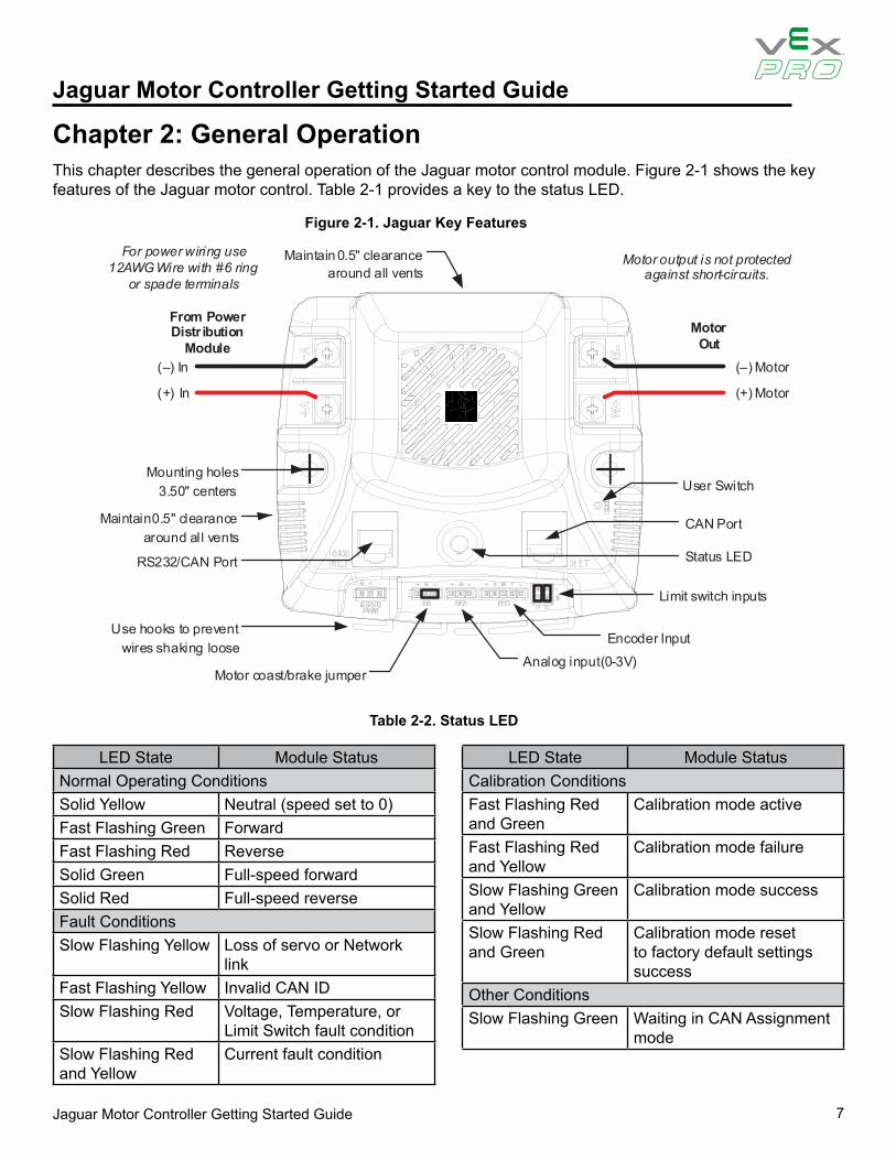
Chapter 2: General OperationThis chapter describes the general operation of the Jaguar motor control module. Figure 2-1 shows the key features of the Jaguar motor control. Table 2-1 provides a key to the status LED.
Figure 2-1. Jaguar Key Features
Table 2-2. Status LED
Motor Out
(–) Motor
(+) Motor
(–) In
(+) In
From Power Distr ibution
Module
Motor output is not protected against short-circuits.
User Switch
Use hooks to prevent wires shaking loose
Maintain 0.5" clearance around all vents
Status LED
Mounting holes 3.50" centers
Motor coast/brake jumper
Maintain 0.5" clearance around all vents
For power wiring use 12AWG Wire with #6 ring
or spade terminals
CAN Port
RS232/CAN Port
Analog input (0-3V)
Encoder Input
Limit switch inputs
LED State Module StatusNormal Operating ConditionsSolid Yellow Neutral (speed set to 0)Fast Flashing Green ForwardFast Flashing Red ReverseSolid Green Full-speed forwardSolid Red Full-speed reverseFault ConditionsSlow Flashing Yellow Loss of servo or Network
linkFast Flashing Yellow Invalid CAN IDSlow Flashing Red Voltage, Temperature, or
Limit Switch fault conditionSlow Flashing Red and Yellow
Current fault condition
LED State Module StatusCalibration ConditionsFast Flashing Red and Green
Calibration mode active
Fast Flashing Red and Yellow
Calibration mode failure
Slow Flashing Green and Yellow
Calibration mode success
Slow Flashing Red and Green
Calibration mode reset to factory default settings success
Other ConditionsSlow Flashing Green Waiting in CAN Assignment
mode

Jaguar Motor Controller Getting Started Guide 8
Jaguar Motor Controller Getting Started Guide
Control MethodServo-Style PWM input CAN/RS232C Interface
Open-Loop Speed Control Yes YesClosed-Loop Speed Control No YesAnalog Position Control No YesEncoder Position Control No YesConfigurable Parameters No YesVoltage, Current Measurement No YesAutomatic Output Ramp Yes YesLimit Switches Yesa Yesb
Coast/Brake Feature Yes Yesb
Firmware Update No Yesa. Limit switch inputs are disabled when in Automatic Ramp mode.b. By default, the jumper sets coast/brake. Network commands can over-ride the jumper setting.
Operating ModesThe Jaguar can be controlled using either the Servo-style PWM Input or the CAN interface. Table 2-3 compares the capabilities of each control method.
Table 2-4. Control Method Comparison
Jaguar supports the simultaneous use of CAN for monitoring and the Servo-style input for speed.
Fault Conditions
A slow flashing Red LED indicates that the Jaguar detected one of the following fault conditions:• Power supply under-voltage• Over temperature• Limit switch activated in the current direction of motion
A slow flashing Red and Yellow LED indicates the following fault condition:• Over current
When a fault condition occurs, the motor shuts down and the LED indicates a fault state during the fault condition and for 3 seconds after the fault cause is cleared (except for the limit switch fault, which is cleared instantly). A slow flashing Yellow LED indicates that the Jaguar is not receiving a valid control signal. A fast flashing Orange LED indicates an invalid CAN ID.
Jaguar Motor Controller Getting Started Guide 9
Jaguar Motor Controller Getting Started Guide
Coast/Brake JumperThe coast/brake signal controls the dynamics of the drive signal to the motor. When set to brake, the Jaguar is able to achieve greater deceleration and holding torque because it decays regenerative current from the motor.The coast/brake signal can be set with a jumper or controlled by a signal from a digital source. A single wire connected to the center (S) pin, is recommended. Do not connect to the + pin (+3.3 V) of this connector as any mis-wiring could damage the Jaguar.The coast/brake jumper setting can be overwritten when using the CAN/RS232 interface.
Power and Motor WiringThe Overview diagram (Figure 2-1 on page 7) shows motor and power connections to the Jaguar. For power wiring, use 10-12 AWG wire terminated with #6 ring or spade terminals. The control is not protected against reverse polarity or short-circuits.
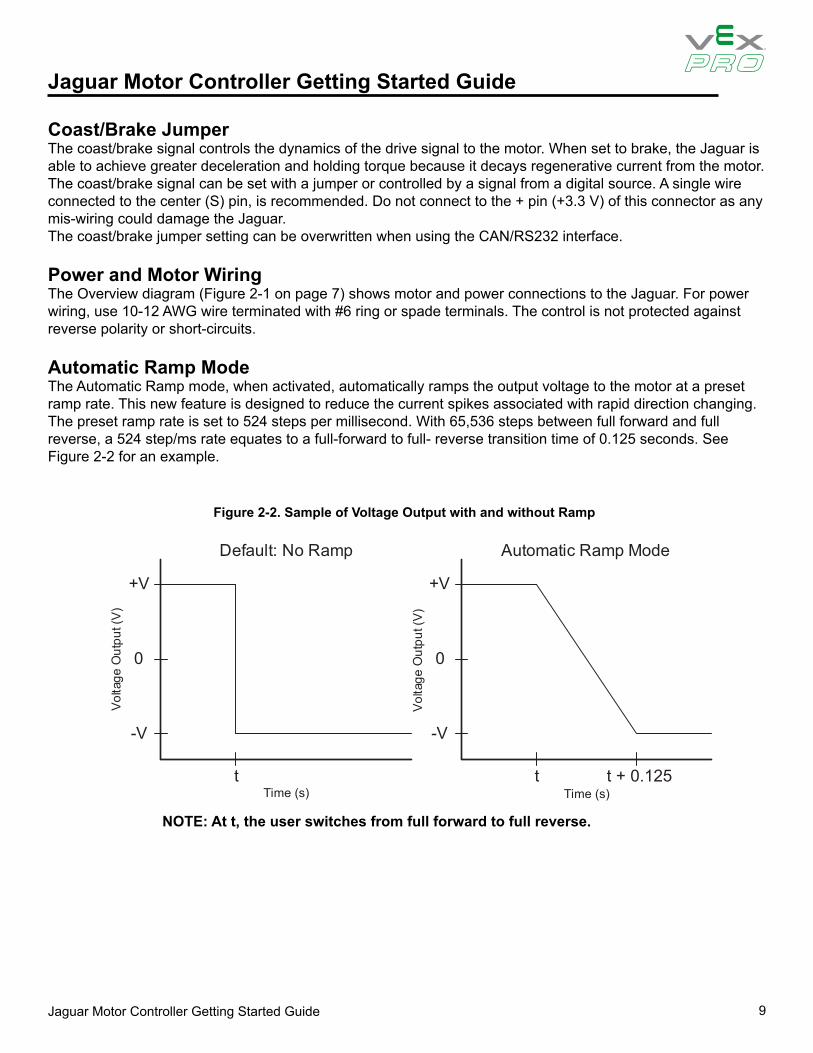
Automatic Ramp ModeThe Automatic Ramp mode, when activated, automatically ramps the output voltage to the motor at a preset ramp rate. This new feature is designed to reduce the current spikes associated with rapid direction changing.The preset ramp rate is set to 524 steps per millisecond. With 65,536 steps between full forward and full reverse, a 524 step/ms rate equates to a full-forward to full- reverse transition time of 0.125 seconds. See Figure 2-2 for an example.
Figure 2-2. Sample of Voltage Output with and without Ramp
+V
-V
0
t + 0.125t t
Vol
tage
Out
put (
V)
Default: No Ramp Automatic Ramp Mode
Time (s)
+V
-V
0
Vol
tage
Out
put (
V)
Time (s)
NOTE: At t, the user switches from full forward to full reverse.
Jaguar Motor Controller Getting Started Guide 10
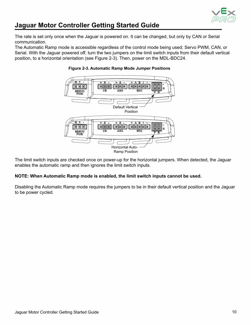
Jaguar Motor Controller Getting Started GuideThe rate is set only once when the Jaguar is powered on. It can be changed, but only by CAN or Serial communication.The Automatic Ramp mode is accessible regardless of the control mode being used; Servo PWM, CAN, or Serial. With the Jaguar powered off, turn the two jumpers on the limit switch inputs from their default vertical position, to a horizontal orientation (see Figure 2-3). Then, power on the MDL-BDC24.
Figure 2-3. Automatic Ramp Mode Jumper Positions
Default VerticalPosition
Horizontal Auto-Ramp Position
The limit switch inputs are checked once on power-up for the horizontal jumpers. When detected, the Jaguar enables the automatic ramp and then ignores the limit switch inputs.
NOTE: When Automatic Ramp mode is enabled, the limit switch inputs cannot be used.
Disabling the Automatic Ramp mode requires the jumpers to be in their default vertical position and the Jaguar to be power cycled.
Jaguar Motor Controller Getting Started Guide 11
Jaguar Motor Controller Getting Started Guide
Motor Out
(– ) Motor
(+) Motor
PWM speed signals from Digital Sidecar
+5VGND
Reverse direction switch(es)
Normally-closedLimit switches
(–) In
nI )+(
From Power Distribution
Module
User Switch
PWMs
+5 V is optional (no internal connection )
Status LED
Forward direction switch(es)
Install jumpers if limit switches are not .desu
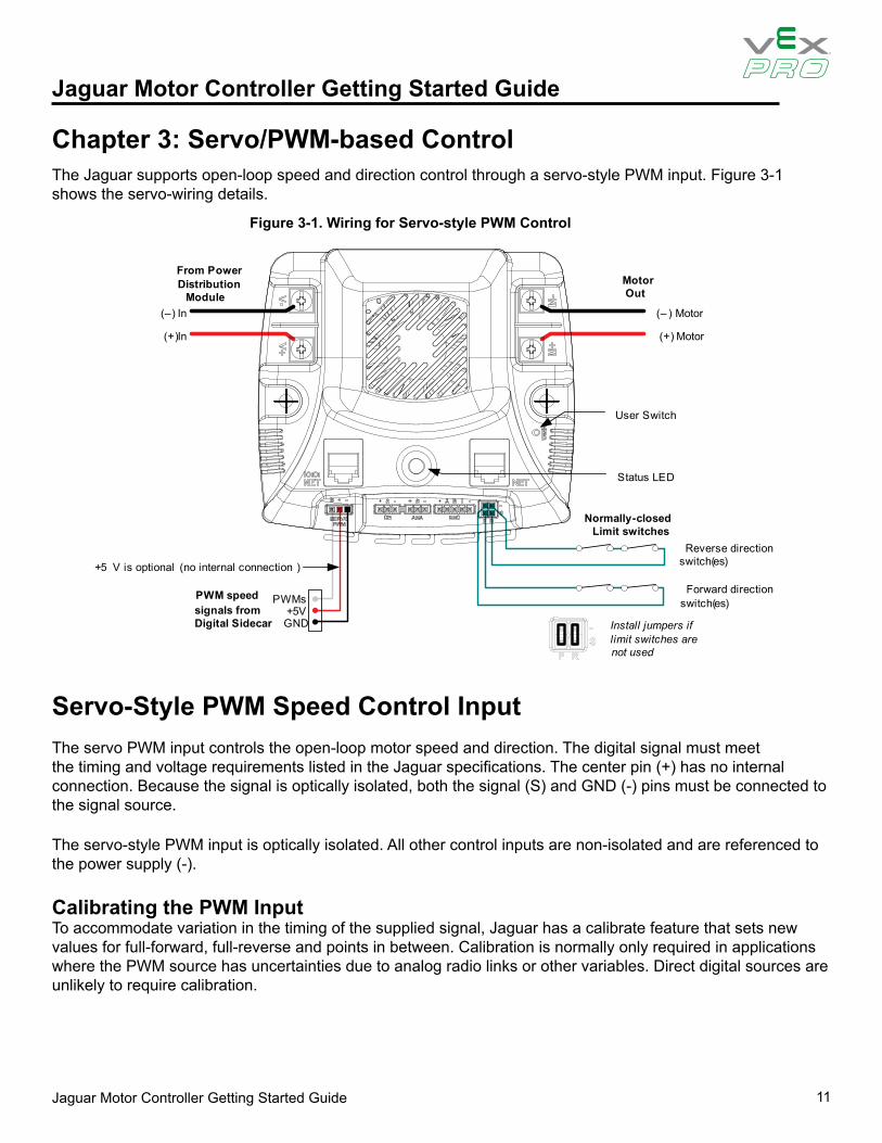
Chapter 3: Servo/PWM-based ControlThe Jaguar supports open-loop speed and direction control through a servo-style PWM input. Figure 3-1 shows the servo-wiring details.
Figure 3-1. Wiring for Servo-style PWM Control
Servo-Style PWM Speed Control InputThe servo PWM input controls the open-loop motor speed and direction. The digital signal must meet the timing and voltage requirements listed in the Jaguar specifications. The center pin (+) has no internal connection. Because the signal is optically isolated, both the signal (S) and GND (-) pins must be connected to the signal source.
The servo-style PWM input is optically isolated. All other control inputs are non-isolated and are referenced to the power supply (-).
Calibrating the PWM InputTo accommodate variation in the timing of the supplied signal, Jaguar has a calibrate feature that sets new values for full-forward, full-reverse and points in between. Calibration is normally only required in applications where the PWM source has uncertainties due to analog radio links or other variables. Direct digital sources are unlikely to require calibration.
Jaguar Motor Controller Getting Started Guide 12
Jaguar Motor Controller Getting Started Guide
To calibrate the servo-style PWM input for a specific range, connect a PWM source, then:
1. Hold down the USER switch with a straightened paper clip for 5 seconds.2. The LED flashes Red and Green to indicate Calibration mode.3. Instruct the controller to send a full-forward signal for one or more seconds.4. Instruct the controller to send a full-reverse signal for one or more seconds.5. The LED flashes Green and Yellow quickly to indicate a successful calibration.
The Jaguar samples these signals and centers the speed range and neutral position between these limits. A calibration failure signals if an out-of-range signal is detected. This condition is indicated by flashing the LED Red and Yellow.
Jaguar Motor Controller Getting Started Guide 13
Jaguar Motor Controller Getting Started Guide
Chapter 4: Introduction to Network-Based Control
The jaguar supports CAN-based control, configuration and firmware updates. The Jaguar also supports the same command set over RS232.
Network Security and System SafetyThe factory default network protocol allows for very flexible control networks with all commands being accepted and executed without restriction. However, a vulnerability is that faulty software has the potential to send errant messages. To address the possibility that motors could run when they are not supposed to, a special set of trusted commands have been added. This capability is supported in an FRC-specific firmware update. The Jaguar must have updated firmware if it is to be used with CAN or RS232 communication in an FRC competition.
Trusted Mode (FIRST Robotics Competition feature)Each Jaguar module expects to see a trusted message from the Host every 100 ms. If a trusted message is not received, the Jaguar will shut down the motor output until trusted communication is restored.
Trusted communication relies on a proprietary protocol that defines a dynamic message token, known only to the host driver and a specific Jaguar.
Non-FIRST users should use the factory-default firmware (available in source form) which does not implement trusted communication.

Jaguar Motor Controller Getting Started Guide 14
Jaguar Motor Controller Getting Started Guide
Chapter 5: Operation using the RS232 InterfaceThe Jaguar supports a full set of network control and configuration functions over a standard RS232C serial interface. The command protocol is essentially the same as the protocol used on the CAN interface allowing the Jag u a r to automatically bridge all commands between the RS232 and CAN interfaces.
RS232 signals are implemented on the left-side NET connector, which has a special IOIOI annotation as shown in Figure 5-1.
Figure 5-1. Jaguar Bridges for RS232 to CAN
Motor Out
(–) Motor
(+) Motor
(–) In
(+) In
From Power Distribution
Module
DB9 Adapter
Connect to Host Controller
(PC, cRIO)
To other CAN Devices
Black Jaguar bridges RS232 to CAN
See Appendix A, “Jaguar Communication Cables,” on page 23 for details of the RS232 cable assembly. The recommended DB9 adapter design contains an integrated CAN terminator.
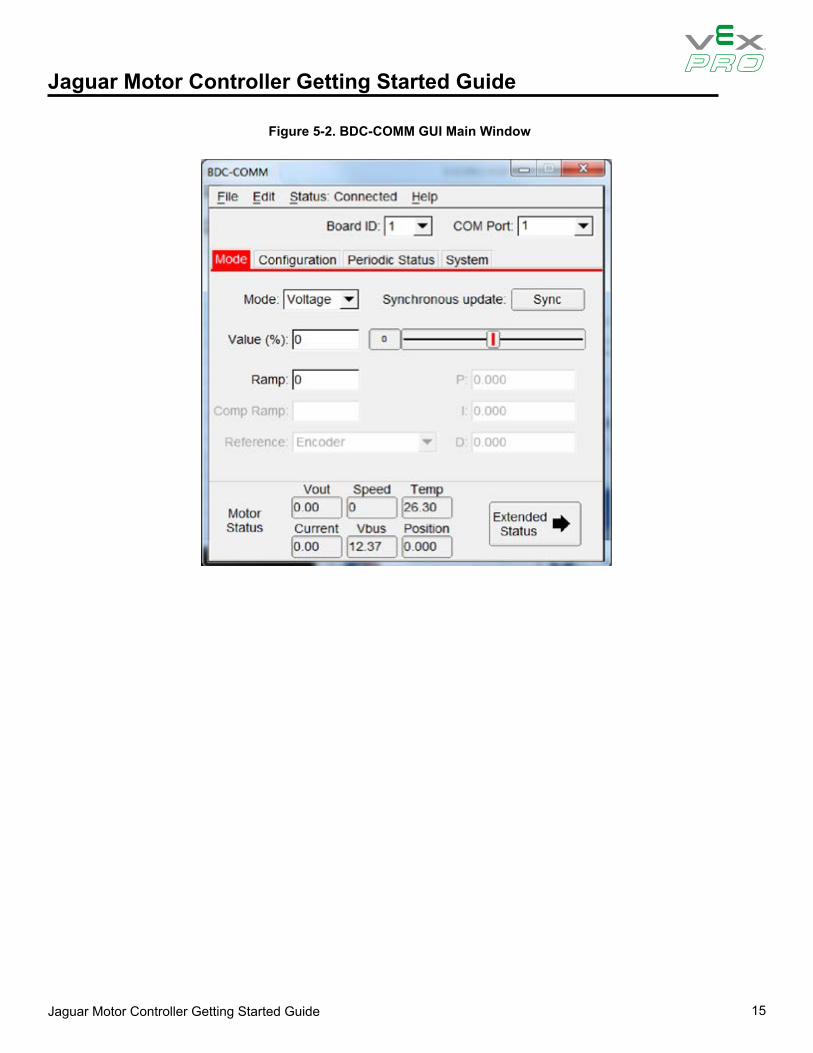
BDC-COMM Application OverviewBDC-COMM is a Windows application for configuring and controlling a Jaguar network using a PC’s RS232 serial port. It is also a convenient tool for performing firmware updates. BDC-COMM requires the use of an Jaguar to bridge RS232 to CAN. Figure 5-2 on page 15 shows the main GUI window of the BDC-COMM application. For more information on using the BDC-COMM application, see the BDC-COMM Application User’s Guide.
Jaguar Motor Controller Getting Started Guide 15
Jaguar Motor Controller Getting Started Guide
Figure 5-2. BDC-COMM GUI Main Window
Jaguar Motor Controller Getting Started Guide 16
Jaguar Motor Controller Getting Started Guide
Chapter 6: Firmware Update Using BDC-COMMFirmware update capability allows VEX Robotics to provide new software, in binary format that contains feature enhancements and bug fixes.
Special firmware releases have been created for FRC 2013. This firmware update must be installed prior to using RS232 or CAN-based control. Firmware update is optional for Servo/PWM control.
Firmware update requires RS232 and CAN cables, at least one Jaguar, the binary file, a PC with an RS232 port, and a 12 V power source.
The BDC-COMM Application User’s Guide contains additional detail on using the tool for firmware update as well as other configuration and control functions.
Important InformationObserve the following precautions when updating firmware:
• We strongly recommend connecting only one Jaguar to the network at a time.• Use the correct binary file.
Step 1: Hardware Setup
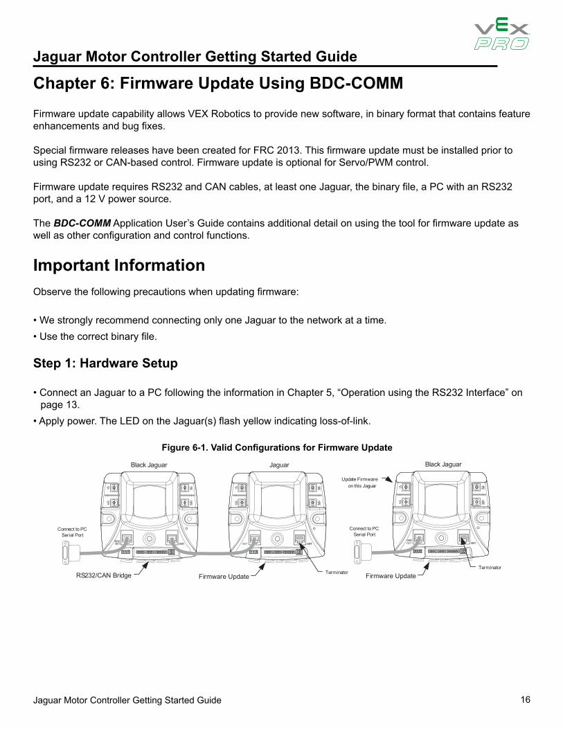
• Connect an Jaguar to a PC following the information in Chapter 5, “Operation using the RS232 Interface” on page 13.
• Apply power. The LED on the Jaguar(s) flash yellow indicating loss-of-link.
Figure 6-1. Valid Configurations for Firmware Update
Connect to PC Serial Port
Connect to PC Serial Port
JaguarBlack Jaguar Black Jaguar
TerminatorTerminator
Firmware Update
Update Firmware on this Jaguar
RS232/CAN Bridge Firmware Update
Jaguar Motor Controller Getting Started Guide 17
Jaguar Motor Controller Getting Started Guide
Step 2: Run BDC-COMM• Run BDC-COMM.EXE.• The LED on the Jaguar(s) should now be solid yellow indicating a valid network link. If the LED is not solid
yellow, check all network connections as well as the BDC-COMM Com Port setting.• A valid link must be established before proceeding to the next step.
Step 3: Assign Unique CAN ID• If two modules are connected, each must have a unique CAN ID. The factory default CAN ID is 1.• Assign the Jaguar modules the ID > 1 so that new Jaguar modules from the factory do not operate on your
robot.• Using the BDC-COMM application, select the System tab and enter a new ID (a unique number from 2..63).• Click “Assign.” The LED on the module(s) starts flashing green.• Press the USER button on the module that is to receive the new ID. This must be done within 5 seconds or
the operation times out.• The module’s LED blinks the number of times that corresponds to the ID if assignment was successful (for
example, if you assign the unique ID number of 5, the LED blinks five times).• A fast-flashing yellow LED indicates an invalid CAN ID. This can occur if an attempt is made to reassign an ID
that is already in use.
Step 4: Update Firmware• A valid link must be established before proceeding. Ensure that the LED indicates solid yellow. It might be
necessary to reconnect to the CAN network to synchronize the trusted link.• Select the board ID that you want to update using the “Board ID” menu.• Select File > Update Firmware from the top menu bar.• Browse to locate the appropriate binary file:• Click OK and then click Update.• A progress bar displays the firmware update progress.• When the firmware update completes, reconnect bdc-comm to the network to re-establish a link.
The System tab in BDC-COMM displays the firmware version.
Jaguar Motor Controller Getting Started Guide 18
Jaguar Motor Controller Getting Started Guide
Chapter 7: Closed-Loop Control OptionsA network-controlled Jaguar supports several types of closed-loop control through an internal PID controller.
• Constant-current control• Position control using an encoder• Position control using a potentiometer• Speed control
Only one mode can be used at a time.
For each control mode, refer to API, VI, or tool documentation for information on which commands to use for configuration.
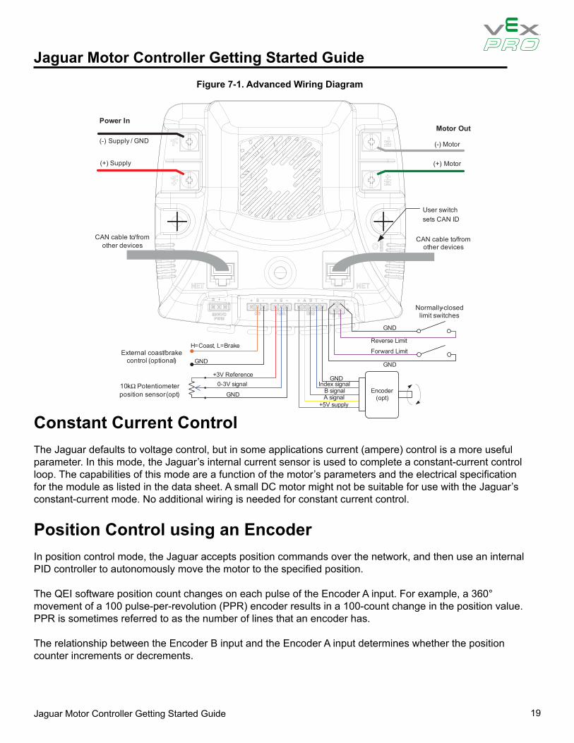
WiringAll closed-loop mode, except for constant-current control, require an external sensor. Figure 7-1 shows an advanced wiring configuration using the CAN interface. The diagram shows wiring for position sensing using both a position potentiometer and a quadrature encoder. Although two sensor types are shown, the MDL-BDC software supports control and monitoring of only one sensor at a time.
Jaguar Motor Controller Getting Started Guide 19
Jaguar Motor Controller Getting Started Guide
(-) Supply / GND
(+) Supply
Power InMotor Out
(-) Motor
(+) Motor
External coast/brake control (optional)
H=Coast, L=Brake
Normally-closedlimit switches
10kΩ Potentiometerposition sensor (opt)
CAN cable to/from other devices
CAN cable to/from other devices
Encoder(opt)
+3V Reference0-3V signal
GND+5V supply
A signalB signal
Index signalGND
GND
GND
GND
Forward Limit
Reverse Limit
User switch sets CAN ID
Figure 7-1. Advanced Wiring Diagram
Constant Current ControlThe Jaguar defaults to voltage control, but in some applications current (ampere) control is a more useful parameter. In this mode, the Jaguar’s internal current sensor is used to complete a constant-current control loop. The capabilities of this mode are a function of the motor’s parameters and the electrical specification for the module as listed in the data sheet. A small DC motor might not be suitable for use with the Jaguar’s constant-current mode. No additional wiring is needed for constant current control.
Position Control using an EncoderIn position control mode, the Jaguar accepts position commands over the network, and then use an internal PID controller to autonomously move the motor to the specified position.
The QEI software position count changes on each pulse of the Encoder A input. For example, a 360° movement of a 100 pulse-per-revolution (PPR) encoder results in a 100-count change in the position value. PPR is sometimes referred to as the number of lines that an encoder has.
The relationship between the Encoder B input and the Encoder A input determines whether the position counter increments or decrements.
Jaguar Motor Controller Getting Started Guide 20
Jaguar Motor Controller Getting Started Guide
An edge on the Index (“I”) input resets the position counter to zero.
The jaguar supports a wide range of shaft encoders. Encoder electrical parameters are detailed in the corresponding data sheets.
If the P, I and D parameters are positive (or zero), the Jaguar expects that a forward condition (+ voltage on White terminal, - voltage on Green) generates increasing counts on the encoder interface. Increasing counts occur when the rising (or falling) edge of the A input leads the rising (or falling) edge of the B input.
If the P, I and D parameters are negative (or zero), the Jaguar expect that a forward condition (+ voltage on White terminal, - voltage on Green) generates decreasing counts on the encoder interface. Decreasing counts occur when the rising (or falling) edge of the B input leads the rising (or falling) edge of the A input.
See Figure 7-1 on page 19 for wiring information. For reliable operation, keep encoder wiring short and route it away from noise sources. The encoder inputs are not electrically isolated.
Position Control Using a PotentiometerPosition control can also be implemented with a single or multi-turn potentiometer. Potentiometers with continuous rotation are not supported.
The Jaguar contains a built-in bias pin for use with 10 k potentiometers. If another potentiometer value or analog source is used, it must have a 0-3 V range.
If the P, I and D parameters are positive (or zero), Jaguar expects that a forward condition (+ voltage on White terminal, - voltage on Green) generates an increasing voltage on the analog input.
If the P, I and D parameters are positive (or zero), Jaguar expects that a forward condition (+ voltage on White terminal, - voltage on Green) generates a decreasing voltage on the analog input.
The analog input is not electrically isolated.
Speed ControlSpeed control can be implemented with either an encoder or with a simple tachometer sensor. If a tachometer sensor is used (such as a gear-tooth sensor), then the signal should be connected to the Encoder ‘A’ input signal, with the ‘B’ and ‘I’ input left unconnected.
The speed set-point is defined in revolutions per second. Adjust the encoder-lines parameter if the sensor generates more than one pulse per revolution.
Jaguar Motor Controller Getting Started Guide 21
Jaguar Motor Controller Getting Started Guide
Chapter 8: Operation Using the CAN InterfaceController Area Network (CAN) provides a powerful interface for controlling one or more Jaguar modules. Jaguar has a 6P6C socket and a 6P4C socket for daisy-chaining modules using standard cables. Each end of the CAN network should be terminated with a 100 resistor.
The CAN protocol used by Jaguar includes the following capabilities:• Firmware update over CAN• Read supply voltage, motor voltage, temperature and current• Set and read motor voltage or target position• Set control mode to speed or position• Configure parameters• Enable features such as closed-loop speed and position control.• Trusted communication with keep-alive commands for fail-safe operation
CAN IDsEach Jaguar on the CAN bus is accessed using an assigned ID number. The ID defaults to 1, but should be changed to a unique value from 2 to 63 by following the ID Assignment procedure. The procedure is detailed in Step 3 of the firmware update procedure in Chapter 6, “Firmware Update Using BDC-COMM”, page 17.
At the network protocol level, ID assignment involves the following:
1. The Host sends Assign ID + number command to all Jaguar modules.2. Pressing the USER switch on a Jaguar informs that particular module to accept the previously specified
ID number and save it to non-volatile memory. The operation times out if a switch is not pressed within 5 seconds.
3. The Jaguar with the new ID assignment sends out a message to let all Jaguar modules know that the ID assignment is complete. Normal operation resumes.
CAN NetworkA CAN network consists of one or more Jaguar modules, an interface or bridge, and a host controller. Figure 8-1 shows a typical configuration.
Jaguar Motor Controller Getting Started Guide 22
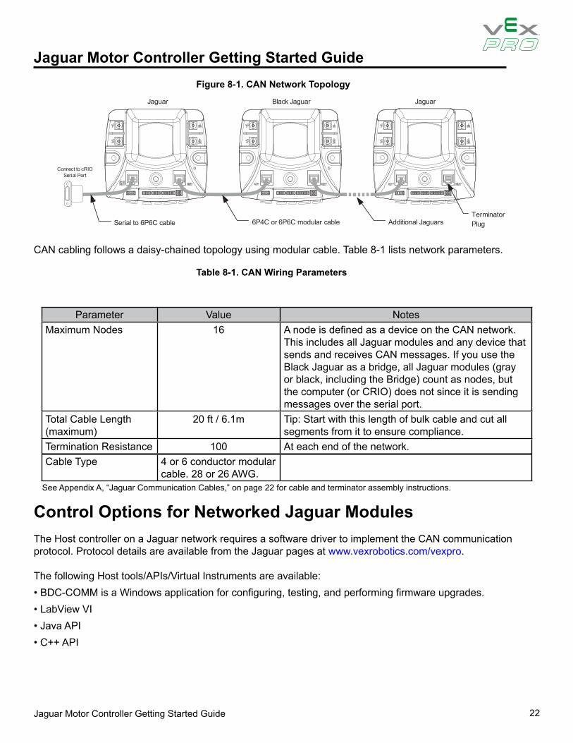
Jaguar Motor Controller Getting Started GuideFigure 8-1. CAN Network Topology
Table 8-1. CAN Wiring Parameters
Connect to cRIO Serial Port
Black JaguarJaguar
Serial to 6P6C cable
Jaguar
Terminator PlugAdditional Jaguars6P4C or 6P6C modular cable
CAN cabling follows a daisy-chained topology using modular cable. Table 8-1 lists network parameters.
Parameter Value NotesMaximum Nodes 16 A node is defined as a device on the CAN network.
This includes all Jaguar modules and any device that sends and receives CAN messages. If you use the Black Jaguar as a bridge, all Jaguar modules (gray or black, including the Bridge) count as nodes, but the computer (or CRIO) does not since it is sending messages over the serial port.
Total Cable Length (maximum)
20 ft / 6.1m Tip: Start with this length of bulk cable and cut all segments from it to ensure compliance.
Termination Resistance 100 At each end of the network.Cable Type 4 or 6 conductor modular
cable. 28 or 26 AWG.See Appendix A, “Jaguar Communication Cables,” on page 22 for cable and terminator assembly instructions.
Control Options for Networked Jaguar ModulesThe Host controller on a Jaguar network requires a software driver to implement the CAN communication protocol. Protocol details are available from the Jaguar pages at www.vexrobotics.com/vexpro.
The following Host tools/APIs/Virtual Instruments are available:• BDC-COMM is a Windows application for configuring, testing, and performing firmware upgrades.• LabView VI• Java API• C++ API
Jaguar Motor Controller Getting Started Guide 23
Jaguar Motor Controller Getting Started Guide
Appendix A: Jaguar Communication Cables
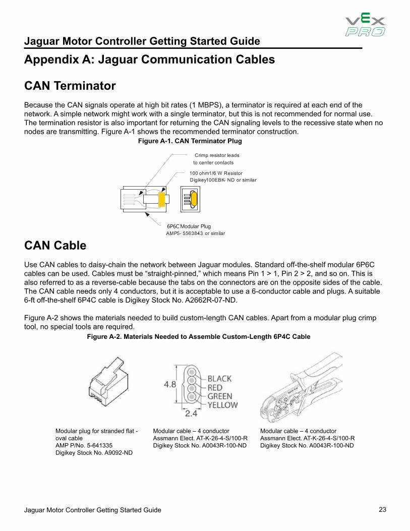
CAN TerminatorBecause the CAN signals operate at high bit rates (1 MBPS), a terminator is required at each end of the network. A simple network might work with a single terminator, but this is not recommended for normal use. The termination resistor is also important for returning the CAN signaling levels to the recessive state when no nodes are transmitting. Figure A-1 shows the recommended terminator construction.
Figure A-1. CAN Terminator Plug
Figure A-2. Materials Needed to Assemble Custom-Length 6P4C Cable
CAN CableUse CAN cables to daisy-chain the network between Jaguar modules. Standard off-the-shelf modular 6P6C cables can be used. Cables must be “straight-pinned,” which means Pin 1 > 1, Pin 2 > 2, and so on. This is also referred to as a reverse-cable because the tabs on the connectors are on the opposite sides of the cable. The CAN cable needs only 4 conductors, but it is acceptable to use a 6-conductor cable and plugs. A suitable 6-ft off-the-shelf 6P4C cable is Digikey Stock No. A2662R-07-ND.
Figure A-2 shows the materials needed to build custom-length CAN cables. Apart from a modular plug crimp tool, no special tools are required.
100 rotsiseR W6/1 mho mis ro DN-KBE001 yekigiD ilar
6P6C Modular Plug -5 PMA 556384- 3 or similar
Crimp resistor leads to center contacts
Modular plug for stranded flat -oval cableAMP P/No. 5-641335Digikey Stock No. A9092-ND
Modular cable – 4 conductorAssmann Elect. AT-K-26-4-S/100-RDigikey Stock No. A0043R-100-ND
Modular cable – 4 conductorAssmann Elect. AT-K-26-4-S/100-RDigikey Stock No. A0043R-100-ND

Jaguar Motor Controller Getting Started Guide 24
Jaguar Motor Controller Getting Started Guide
CAN Cable Assembly
Follow these steps to complete cable assembly (shown in Figure A-3):1. Cut modular cable to length2. Use the crimp to strip the outer jacket from each end of the cable.3. Insert wires into the modular plug and load into crimper.4. Close crimper to complete the connections and secure the cable.
Figure A-3. Completed Cable Assembly
Figure A-4. Materials Needed to Assemble RS232 Cable Components
Modular Plug
4or 6 conductor cable
CAN Cable Pin Assignments
Plug Wire Color Jaguar Use1 Black -2 Red CAN H3 Green CAN L4 Yellow GND
RS232 Cable
Figure A-4 shows the materials needed to build the RS232 cable. Apart from a soldering-iron, no special tools are required.
Resistor 100Ω 1%panasonic ERO-S2PHF1200Digikey Stock No. P100CACT-ND
Modular cord6 contact 6 conductor, reversedAssman Elect. AT-S-26-6/B-7/R-RDigikey Stock No. 046-0003-ND
Modular adapter6P6C to DB-9 FemaleCUI P/No AMK-0003Digikey Stock No. 046-0003-ND
Heatshrink Tubing 1/8” diameterDigikey Stock No. Q2F018B-ND

Jaguar Motor Controller Getting Started Guide 25
Jaguar Motor Controller Getting Started Guide
RS232 Cable Assembly
Follow these steps to complete cable assembly (shown in Figure A-4):
1. Take the Modular Adapter and cut the black wire as short as possible. This wire is unused.2. Cut off the terminals on the Red and Green wires. Strip then solder the Red and Green wires to the 100
resistor. Use a section of heat shrink to protect the resistor and solder connections.3. Insert remaining terminals into the DB9 receptacle. Pin numbers are indicated on the plastic connector body.
– White/Pin 3– Blue/Pin 2– Yellow/Pin 5
4. Slide the back-shell over the connector, then insert the modular cable to complete the assembly.
RS232 Cable Pin Assignments
6P6C Wire Color Jaguar Use PC Use DB9 Pin1 White RXD TXD 32 Black - - -3 Red CAN H - -4 Green CAN L - -5 Yellow GND GND 56 Blue TXD RXD 2
External ReferencesThe following references are also useful for working with the Jaguar:• The Jaguar Data Sheet contains detailed electrical specifications and connector details.• The Jaguar User’s Guide provides instructions on how to use the BDC-COMM GUI and command line
applications to control Jaguar networks.• Jaguar FAQ