Embed Size (px)
DESCRIPTION
dem
Citation preview

Powder Technology 283 (2015) 32–47
Contents lists available at ScienceDirect
Powder Technology
j ourna l homepage: www.e lsev ie r .com/ locate /powtec
Investigation of screening performance of banana screens usingLIGGGHTS DEM solver
M. Jahani, A. Farzanegan ⁎, M. NoaparastSchool of Mining Engineering, University College of Engineering, University of Tehran, P.O. Box 11155-4563, Tehran, Iran
⁎ Corresponding author. Tel.: +98 9122898806; fax: +E-mail address: [email protected] (A. Farzanegan).
http://dx.doi.org/10.1016/j.powtec.2015.05.0160032-5910/© 2015 Elsevier B.V. All rights reserved.
a b s t r a c t
a r t i c l e i n f oArticle history:Received 28 February 2015Received in revised form 30 April 2015Accepted 9 May 2015Available online 15 May 2015
Keywords:SimulationDiscrete Element MethodBanana screensDEM software LIGGGHTSScreening performance
Deeper understanding of screening performance of banana screens helpsmineral processing engineers to controland optimize them. In this article, screening performance of banana screens using a DEM (Discrete ElementMethod) solver ‘LIGGGHTS’ is investigated. An industrial double-deck banana screen with five panels and twolaboratory single-deck banana screens with three and five panels are simulated. Effects of design parametersincluding incline angle of each panel, vibration amplitude and vibration frequency on screening performanceof both the industrial screen and laboratory screens are studied. Also, the effects of operational parametersincluding simulation time and feed particle size distribution on screening performance of the industrial screenare examined. Simulation results are expressed in terms of recognized and comprehensible quantities forengineers, i.e., screen efficiency and screening recovery. To validate simulation results, a parameter namedpartition number is defined. Comparison of the partition numbers of simulations related to the laboratory screenswith those available in the literature demonstrates a good agreement which validates the DEM simulations andthe used software. Also, the results indicate that the industrial and laboratory screens show a totally differentbehavior with respect to changes in design parameters.
© 2015 Elsevier B.V. All rights reserved.
1. Introduction
The processing of granular materials is central to the mineral pro-cessing industry. One of the critical stages commonly employed in thetreatment of these materials, is the separation of constituent partsbased on size by screening processes. The better understanding ofsuch processes is critical in optimizing these industrial activities, asscreens are often inefficient in their action which leads to poor separa-tion and quality issues that impact the production of final products[1]. Screening and sieving have been widely used in various industries,as a unit operation for large-scale separation of particles according tosize, and in laboratories, as a tool for the analysis of particle size distribu-tion, usually at a small scale [2,3]. Mineral processing equipmentperforms best when the feed material consists of a narrow particlesize distribution. Thus, in many cases it is customary to subject thefeed material to a size separation stage prior to another processingoperation [5]. Screening is the most widely used sizing method atcommercial scale [6]. Among the major factors which influence theperformance of screening operations, particle-to-aperture ratio, particlesize and shape, nature of the screening surface, feed rate, feed composi-tion, and vibratorymotion are important. Of these variables, the effect ofthe vibratory motion is the least quantified [5].
98 2188631202.
Laboratory banana screens are specially designed vibrating screensin which the slope of the screen changes from steep at the feed end toflat at the discharge end in order to maintain a constant bed thickness.This is normally realized by a combination ofmulti-panels having differ-ent incline angles [4]. While these kinds of screens can double thecapacity in the mineral processing, their control and optimizationunder different conditions is an important issue for their applications,which requires fundamental understanding of this screening process[4]. Industrial double deck banana screens consist of one ormore curveddecks fitted with screen panels having square or rectangular openingsand often used for high capacity size separation of iron ore, coal andaggregates [7]. These screens have many adjustable parameters andare much less well understood than conventional flat vibrating screens.The screen structure is usually vibrated with frequency around 15 Hz. Adense stream of particles is loaded onto the upper end of the screen.They accelerate down the steeper early panels of the screen and slowas the panel angle decreases towards the discharge end. The materialdischarging from the top of the deck is the oversize and may becomea coarse product or be crushed and recycled to the screen feed. Thematerial falling through the deck openings can be further separated byan additional deck below [8]. On the lower deck thismaterial undergoesfurther sorting to return a product stream via the exit chutewith under-sizedmaterial passed to the underflow. All multi-deck screens are diffi-cult to sample for intermediate products. Banana screens are moredifficult because the screen cut size varies with the slope of the deck

33M. Jahani et al. / Powder Technology 283 (2015) 32–47
[7]. The screen performance can strongly affect the overall circuitperformance [8].
Simulation has become a common tool in the design and optimiza-tion of industrial processes [9–11]. The continuous increase in comput-ing power is now enabling researchers to implement numericalmethods that do not focus on the granular assembly as an entity, butrather deduce its global characteristics from observing the individualbehavior of each grain [12]. Due to their highly discontinuous nature,one should expect that granular media require a discontinuous simula-tionmethod. Indeed, to date the Discrete ElementMethod (DEM) is theleading approach to those problems [12]. Because of its inherent advan-tages in analyzing granular materials, DEM has been developed rapidlyin recent decades and is used widely in mineral processing engineering[13–15]. The Discrete Element Method is a powerful numerical tool forsimulating the mechanical behavior of systems with a large number ofparticles based on particles'motion and interactions and their represen-tation as rigid geometric bodies, commonly having spherical shape [16,17]. Whereas simulations with spherical particles can include millionsof particles, usingnon-spherical particles is still not an easy task.Where-as for spherical particles the geometry is described by the radius and theinteraction forces can easily be calculated by contact laws like Hertziancontact, for non-spherical particles the geometry representation andcalculation of contact forces are much more complex [16,18]. DEM isbased on the Lagrangian approach and treats granular material as anassemblage of distinct particles, each governed by physical laws [19,20]. Each particle interacts with its neighbors through particle-to-particle contacts which can be formed or broken at each time step [17,19,21–23]. In recent years, the drastic increase in affordable computa-tional power has allowed DEM simulations to become a versatile toolfor industrial applications [24]. Recent advances in discrete elementmodeling have resulted in this method becoming a useful simulationtool that can provide detailed information not easily measured duringexperiments [25]. With the maturing of DEM simulation, it is nowbecoming possible to run simulations of millions of particles withcomplex shapes and inter-particle cohesive forces in tolerable timeson single processor, desktop computers [9,24–26].
There are no general models that are applicable to complex screen-ing processes used in the industry, including the process of screeningby the banana screens [4,27]. The insight into understanding the com-plex screening process requires that studies be carried out on a particlescale.While this is often difficult to realizewith the existing experimen-tal techniques, numerical simulation based on DEM is an effective wayto perform such studies. However, its application to screening operationis rather preliminary, limited to simple processes [2,3,9,23]. Cleary andSawley [23] and Cleary [9] presented a three dimensional model ofspherical particle separation on a periodic section of an inclined flatscreen. Cleary [24] presented a comparison of different separationperformances obtained using spherical and non-spherical particles onthe same screen. Li et al. [3] performed DEM modeling of non-periodicscreens, but these were limited to two dimensions, small numbers ofcircular particles with little or limited size variation. Recently Clearyet al. [8,28] performed extensive DEM analysis of the performance of afull industrial scale iron ore scalping double-deck banana screen usingsuper-quadric shaped particles. They analyzed transport and separationon each deck and the identification of the specific contributions of eachpanel for a range of peak accelerations. They also analyzed powerconsumption, particle degradation and screen wear. At the same time,Dong et al. [4] have presented a numerical study of the particle flowon a banana screen as a function of vibration parameters includingfrequency, amplitude, and type of vibratory motion. DEM was used forthat study and the role of each parameter on screening efficiency wasdetermined [4]. They used DEM to evaluate the influence of deck vibra-tion and particle speed on separation of a laboratory single-deck bananascreen. They used spherical particles and the grate openingswere repre-sented as long slots rather than having square or rectangular openings.They investigated 3 and 5 panel variants for this configuration [4].
Finally, Delaney et al. [1] have made detailed comparison of predictedseparation efficiency of DEM using spherical particles with careful andwell characterized experiments in a flat horizontal laboratory scalevibrating screen for a range of flow rates (or bed depths).
LIGGGHTS is an open-source software package for modeling granu-larmaterial bymeans of DEM. LIGGGHTS stands for ‘LAMMPS Improvedfor General Granular and Granular Heat Transfer Simulations’ and isbased on LAMMPS[29]. LAMMPS (Large-scale Atomic/MolecularMassively Parallel Simulator) is an open-source classical moleculardynamics package for simulating the dynamics of interacting atoms. Italso includes coarse-grained particles and interaction potentials, so itcan model materials at the mesoscale as well [30]. LAMMPS has beenwritten in C++ and can run either on a single processor or a multi-processor system in parallel. In parallel processing, LAMMPS can runvery large problems (tens of thousands of processors, billions ofparticles) and achieve high parallel efficiencies of 90% or more [30].Open source codes represent a viable alternative to existing commercialsoftware [31,32].
DEM simulations may involve particle collisions, particles withenduring contacts, or both. It is therefore extremely difficult to trulyvalidate DEM simulations. Attempts to quantitatively validateDEMsimulations by comparing with experimental data are often frus-trated by uncertainties in terms of the experimental data and the factthat frequently the simulated particles are spheres and the experimen-tal particles are non-spherical[33]. To date, the validation of DEM simu-lations for screening has been very limited, with 2D DEM simulationsbeing shown to have some qualitative agreement [2,3]. However, nodetailed 3D comparisons with experimental systems have been per-formed to assess the accuracy of the DEM model [1].
In this study, the Discrete ElementMethodwas employed to directlysimulate the screening process of banana screens. The screening processwas simulated in three dimensions through an open source code,LIGGGHTS. In order to conduct the DEM simulations, the original opensource code of LIGGGHTS was modified by the authors. In this work,we used the same geometries for the laboratory scale three-panel andfive-panelsingle-deck banana screens as used in Dong et al. [4] as wellas we used the same geometry for the full industrial scale double-deckbanana screen as used in Cleary et al. [8,28] and Fernandez et al. [7].Considering that screening is one of the most important operations inmineral processing plants, as well as regarding that the simulationresults should be in such a way that to be understood by the engineersof that field in order to help them in operation optimization and control,therefore, the simulation results should be expressed in terms of screenefficiency which is a recognized and comprehensible quantity for them.However, inmost of the previous researches conducted on the (banana)screens often the simulation results either were expressed qualitativelywhich are not usable for engineers or were expressed quantitatively interms of parameters such as particle velocities and volumewhich limitstheir use and application by engineers. Therefore, in this article thesimulation results in terms of screen separation efficiency for laboratoryscreens and based on screening recovery, i.e., the product of mass (%) ofunder process materials by screen separation efficiency, for industrialscreens were expressed. Also, the effect of screen design parametersincluding changing incline angle of each panel, screen vibration ampli-tude, and screen vibration frequency on screening recovery of a full-industrial scale double-deck banana screen and on separation efficiencyof laboratory scale three-panel and five-panelsingle-deck bananascreens was simultaneously investigated and compared. Additionally,the effect of operational parameters including increasing simulationtime and changing feed particle size distribution on screening recoveryof the industrial double-deck banana screen was investigated. In thisarticle, in order to validate the simulation results, a parameter named‘partition number’ was used [4]. The DEM simulations as well as theused software were validated against data available in the literature[4] bymaking a detailed quantitative comparison between the partitionnumbers of the simulations conducted by LIGGGHTS software for

34 M. Jahani et al. / Powder Technology 283 (2015) 32–47
laboratory three-panel and five-panel banana screens and the partitionnumbers of the conducted simulations under similar conditions byDong et al. [4].
2. DEM simulation
2.1. The DEM solver “LIGGGHTS”
With the development of DEM theory, many DEM codes such asTrubal and GRANULA were developed, becoming important tools forDEM research. After the 1990s, commercial DEM software began toappear: UDEC, 3DEC, PFC2D, and PFC3D. In particular, PFC2D andPFC3D, with their advantages of fast calculation speed and effectivesimulation of large deformation, have been used widely in particlematerial analysis [13]. However, the core code of a commercial DEMsoftware is a black box for software users and thus limits their abilityto extend applications. Although commercial software is convenient, itis usually costly and often limits a researcher's ability to modify andimprove the existing code-base. A common solution is for researchersto write code to perform a specific simulation. This has led to theappearance of some open source DEM codes such as LMGC90, YADE,and LIGGGHTS[13].
For the DEM simulations, we developed a version of the LIGGGHTSpackage adapted to our needs. LIGGGHTS is an open source softwarepackage for modeling granular material by means of the DiscreteElement Method [29,34,35]. LIGGGHTS stands for “LAMMPS Improvedfor General Granular and Granular Heat Transfer Simulations” and isbased on LAMMPS (“Large Atomic and Molecular Massively ParallelSimulator”), an open source Molecular Dynamics code by SandiaNational Laboratories for massively parallel computing on distributedmemory machines [36,37]. LAMMPS is a parallel particle simulator atthe atomic, meso-, or continuum-scale. If coarse-grained granular parti-cles are simulated, this method is termed DEM as will be discussed inthe next section [29,35]. LAMMPS offers implementations for bothlinear (Hooke) and non-linear (Hertz) granular potentials. LIGGGHTSimproves these features for granular simulations, comprising geometryimport from CAD files and a moving mesh capability, features forparticle insertion and packing, multiple contact models, non-sphericalparticle handling by means of the multi-sphere method, a bondedparticle model, wall-stress analysis and wear prediction, and a sixdegree-of-freedom capability for rigid bodies [29]. Both LIGGGHTS andLAMMPS run on single processors or in parallel using message-passingtechniques (MPI) and a spatial-decomposition of the simulationdomain. The code is designed to be easy to modify or extend withnew functionality [29,35]. Both LIGGGHTS and LAMMPS are distributedas open source codes under the terms of the GNUGeneral Public License[38]. In LIGGGHTS software application, it is possible to program user-defined contact models but there is no user interface and all the codehas to be scripted to describe the simulation process. Visualization ofsimulations is possible by translating the data of LIGGGHTS with PIZZAand loading them into ParaView [39].
2.2. The Discrete Element Method (DEM)
The Discrete Element Method is a numerical technique used topredict the behavior of collision dominated particle flows. Each particlein the flow is tracked and all collisions between particles and betweenparticles and boundaries are modeled. The DEM variant used here issometimes called a ‘soft particle method’. The particles are allowed tooverlap and the extent of overlap is used in conjunction with a contactforce law to give instantaneous forces from knowledge of the currentpositions, orientations, velocities and spins of the particles [40]. Herewe have used the Hertz–Mindlin's contact force law. It states that therepulsive force resulting from a collision is calculated from the amountof normal overlap, δn and tangential overlap δt (soft-sphere approach)[41]. This granular model uses the following formula for the frictional
force between two granular particles, when the distance r betweentwo particles of radii Ri and Rj is less than their contact distance d =Ri + Rj. There is no force between the particles when r N d:
F ¼ kn δni j–γn vni j� �þ kt δti j–γt vti j
� �: ð1Þ
The first term is the normal force (Fn) between the two particles andthe second term is the tangential force (Ft). The normal force has twoterms, a spring force and a damping force. The tangential force alsohas two terms: a shear force and a damping force. The shear force is a“history” effect that accounts for the tangential displacement (tangen-tial overlap) between the particles for the duration of the time theyare in contact.
The quantities in the equation are as follows:
kn elastic constant for normal contactδnij d − r = normal overlap (overlap distance between the two
particles)γn viscoelastic damping constant for normal contactvnij normal relative velocity (normal component of the relative
velocity of the two particles)kt elastic constant for tangential contactδtij tangential overlap (tangential displacement vector between
the two spherical particles which is truncated to satisfy africtional yield criterion)
γt viscoelastic damping constant for tangential contactvtij tangential relative velocity (tangential component of the
relative velocity of the two particles).
Static friction is obtained by keeping track of the elastic shear dis-placement throughout the lifetime of the contact. The magnitude ofδtij (the tangential overlap) is truncated as necessary to fulfill a localCoulomb yield criterion: Ft≤ μFn, where μ is the grain–grain friction co-efficient. Therefore, the contact surfaces are treated as sticking whenFt b μFn, and as slipping when the Coulomb yield criterion is satisfied[42].
Considering that the shear modulus (G) can be calculated fromYoung's modulus and Poisson ratio, the Hertz–Mindlin contact modeldepends on the following material parameters [41]:
Coefficient of restitution, eYoung's modulus, YPoisson ratio, νCoefficient of static friction, μsCoefficient of rolling friction, μr.
The maximum overlap between particles is determined by thestiffness kn of the spring in the normal direction. Typically, averageoverlaps of 0.1–0.5% are desirable, requiring spring constants of theorder of 104–106 N/m in three dimensions. The normal dampingcoefficient γn is chosen to give the required coefficient of restitution e(defined as the ratio of the post-collisional to pre-collisional normalcomponent of the relative velocity) [43].
For the Hertz–Mindlin model, the kn, kt, γn, and γt coefficients arecalculated as follows from the material properties:
kn ¼ 43Y� ffiffiffiffiffiffiffiffiffiffi
R�δnp
ð2Þ
γn ¼ −2
ffiffiffi56
rβ
ffiffiffiffiffiffiffiffiffiffiffiffiSnm�
p≥0 ð3Þ
kt ¼ 8G� ffiffiffiffiffiffiffiffiffiffiR�δn
pð4Þ

35M. Jahani et al. / Powder Technology 283 (2015) 32–47
γt ¼ −2
ffiffiffi56
rβ
ffiffiffiffiffiffiffiffiffiffiffiStm�
p≥0: ð5Þ
The following equations can be defined for two particles in contact(Eqs. (6)–(12)):
Sn ¼ 2Y� ffiffiffiffiffiffiffiffiffiffiR�δn
pð6Þ
St ¼ 8G� ffiffiffiffiffiffiffiffiffiffiR�δn
pð7Þ
β ¼ ln eð Þffiffiffiffiffiffiffiffiffiffiffiffiffiffiffiffiffiffiffiffiffiffiffiffiffiffiln2 eð Þ þ π2
q ð8Þ
1Y� ¼
1−ν12
� �Y1
þ 1−ν22
� �Y2
ð9Þ
1G� ¼
2 2þ ν1ð Þ 1−ν1ð ÞY1
þ 2 2þ ν2ð Þ 1−ν2ð ÞY2
ð10Þ
1R� ¼
1R1
þ 1R2
ð11Þ
1m� ¼
1m1
þ 1m2
ð12Þ
where Y is the Young'smodulus, G is the shearmodulus, ν is the Poissonratio, e is the coefficient of restitution, m is the mass and R is the radiusof a particle. The subscripts 1 and 2 stand for the two particles incontact.
Industrial applications place heavy demands on the geometricalcapabilities of DEM codes and can affect computational performance.Boundary objects are defined here, for three dimensions, by triangularsurface meshes. These meshes can be produced using any reasonablemesh generator from solid models generated in suitable CAD packages.This provides enormous flexibility in specifying three-dimensionalenvironments with which the particles interact [9–11,43].
In DEM, particles are traditionally approximated by disks or spheres,in two and three dimensions, respectively. These shapes are preferredbecause of their computational efficiency. The contact is always on theline joining the center of each particle and is as simple as comparingthe distance between their centers to the sum of their radii [24,26].The shape of the granular material in DEM is usually assumed to bespherical for ease of contact detection or calculation of contact force,although particles in the screening process have completely irregularshapes. The best solution for considering particle shape in DEM is tomodel the exact particle shape. However, this is very difficult becausethe calculation load becomes extremely large, hence not suitable tosimulate granular flow in the screening process, because there areinnumerable particles involved in this process [2,3].
The drawback of the DEM method is that the time step has to bechosen extremely small because the contact force exhibits a very stiffbehavior. Depending on the material properties and the particle sizethe time step size can be as low as 10−6 s for an accurate simulation[44]. Thanks to advancing computational power, the DEM has becomemore and more accessible lately. On actual desktop computers, simula-tions of up to a million particles can be performed. On very largeclusters, the trajectories of hundreds of millions of particles can becomputed [29,35,44].
DEMmethod uses an explicit numerical scheme to trace the motionof individual particles according to their interaction with each other [4,27]. In the framework of the DEM, all particles in the computational do-main are tracked in a Lagrangian way, explicitly solving each particle's
trajectory, based on the force and torque balances [29,35,44,45]. Foreach particle, the translational motion and rotational motion, whichcan be described by Newton's second law of motion, are respectivelydetermined by:
v� ¼
XF
mþ g ð13Þ
ω� ¼X
MI
ð14Þ
where v is the vector of a particle velocity, F is the contact force actingon a particle, m and g are the mass of a particle and the gravitationalacceleration, ω is the vector of angular velocity, and M and I denotethe moment caused by the tangential force and the moment of inertia.By knowing the various forces (contact and gravitational forces) actingon particles, the velocity and the trajectory of each individual particleare computed by integration with time. This allows all particles to beregistered in a predefined domain and, therefore, the interactionsbetween particles and with boundaries can be precisely calculatedusing the local particle and boundary properties [2,3].
3. Banana screen geometry and simulation conditions
In this work, laboratory scale single-deck banana screens with threeand five panels and a full-industrial scale double-deck banana screenare simulated (Fig. 1). The laboratory screens are according to thedimensions described in Dong et al. [4] and the industrial screen isaccording to the dimensions described in Cleary et al. [8,38] andFernandez et al. [7]. The detailed geometrical and operational conditionsand material properties for the laboratory screens and the industrialscreen are listed in Tables 1 and 2, respectively.
In the literature [4,7,8,27,28], for both industrial and laboratoryscreens, the particles were fed continuously. However, for laboratoryscreen simulations all particles should be fed at once (not continuously),because the actual operation is in batch mode and all feed particles areplaced on the screening surface before starting screening process. Forthis reason, in previous studies [4,27], the simulations conducted forlaboratory screens were not able to accurately predict the real processperformance.
Since in laboratory screen simulation trials performedby the authorsall particles are presented into screening surface at once, thus, all parti-cles undergo screening process during simulation time. In these screens,a simulation begins by discharging the mixture of particles from thefeed end, with a certain size distribution and feed flow rate. The parti-cles that reach the mesh will be either sieved or flow along the screento the discharge end [4,27]. The simulation termination time is whenall particles have been processed and entered oversize or undersizeproduct. Here, in the simulations conducted for the laboratory screens,simulation time is considered 2.5 s. Fig. 2 demonstrates snapshots ofthe simulations of the three-panel and five-panel banana screens atthe middle and end of the simulations. Also, the number of particlesremaining on and passing through each panel at the end of simulationsaswell as the total number of overscreen and underscreen particles andtheir mass (%) are observable.
In the industrial screen simulations because the operation is contin-uous, particles enter the screen gradually in several stages. Thus, duringsimulation run only part of particles undergo screening process and byincreasing simulation time the number of particles which undergoscreening process increases. The data are monitored to determine if amacroscopically steady state is achieved, at which point the inlet flowrate (feed flow rate) equals the outlet flow rate (which is the sum ofthe flow rates of the underflow and overflow) for each size group ofparticles [4,27]. In previous studies [4,27], the steady state conceptwas proposed for the laboratory screens but there is no steady state inlaboratory screens because the operation is in batches and operation

Fig. 1. 3D CAD geometry of the laboratory and industrial banana screens used in the sim-ulations: (a) the laboratory 3-panel single-deck screen, with incline angles of panels 1, 2,and 3 being 34°, 22°, and 10°, respectively; (b) the laboratory 5-panel single-deck screen,with incline angles of panels 1, 2, 3, 4, and 5 being 30°, 22.5°, 15°, 7.5°, and 0°, respectively;(c) the industrial 5-panel double-deck screen, with incline angles of panels 1, 2, 3, 4, and 5being 33°, 27°, 21°, 15°, and 10°, respectively.
Table 1Parameters used for the DEM simulations of the laboratory screens.
Screen width (mm) 9.0Aperture size (mm) 1.0Wire length (mm) 5.0Open area (%) 17Particle size, d (mm) 2.0 1.7 1.4 1.1 0.9 0.6 0.45Feed rate (number/s) 150 244 440 900 1640 5560 26,320Feed size distribution (%) 12.5 12.5 12.5 12.5 12.5 12.5 25.0Feed height (mm) 30Vibration frequency, f (Hz) 15 (5–25)Vibration amplitude, A (mm) 2.0 (1.0–3.0)Vibration motion Linear, 45° with horizontal lineParticle density (kg/m3) 1400Young's modulus (N/m2) 5 × 10⁴a
Poisons ratio 0.45Coefficient of restitution 0.3Sliding friction coefficient 0.5Rolling friction coefficient 0.01
a Note that Young's modulus in the simulations is much smaller than that of real coal(~10 MPa). As the time step in DEM is inversely proportional to the hardness, a smallerYoung's modulus can reduce simulation time considerably.
36 M. Jahani et al. / Powder Technology 283 (2015) 32–47
must be treated as a dynamic process. The concept of steady state isapplicable only to continuous operations when they are not in a transi-tion state. Here, only the data collected at the steady state will be usedfor simulation result analysis. Fig. 3 demonstrates snapshots of thesimulations of the industrial double-deck banana screen at the steadystate at the time of 13 s for feed size distribution 1. Particles are fedinto the screen at the top end of the screen. In the simulations of theindustrial screen, we use a conveyor feeder to provide the feed stream.As particles flow down along the top deck, they accelerate with someparticles smaller than the aperture size being trapped and fallingthrough to the bottom deck below. Particles that are not able to passthrough the screen deck, either because they are too big to pass through
the holes or due to insufficient residence time, are discharged from theend of the top deck. A streamof these oversize particles is then collectedby the top deck chute where they are slowed and allowed to flow downonto the overscreen conveyor [8]. The bottom deck has a similar overallstructure, with a banana shape parallel to the top deck and five sets ofpanels along its length. The panel angles are the same as for the topdeck. Unlike for the top deck where the feed material enters at thestart of the top deck, material falls onto the bottom deck along its entirelength. This means that the loading and flow on the bottom deck aresubstantially different to the top deck. The bottom deck is fully enclosedand it is extremely difficult to photograph or measure anything aboutthe dynamics of this critical part of the screen responsible for the sepa-ration of the screen product [8]. Thematerial falling from above collectson the bottomdeck to form a flowing bedwhich again accelerates downthe inclined slope of the cloth. Particles small enough can be trapped bythe holes and fall onto the underscreen conveyor which passes directlyunder and parallel with the screen. Particles which are either too largeto pass through the bottom deck holes or do not have an opportunitybecause of their location in the flow, discharge from the end of thebottom deck. These particles are collected by the bottom deck chutewhere they are slowed and dropped down onto the middle conveyor[8] (Fig. 3). Also, the number of particles and their mass (%) on theoverscreen, middle, and underscreen conveyors as well as the mass(%) of under process particles at the end of the simulation (13 s) areobservable in Fig. 3.
4. Results and discussion
In overall, 67 simulations were performed in this research (Table 3).The first six simulations have been performed using a powerful super-computer and other simulations were performed using a laptop PC.Simulation of industrial screens such as the double-deck banana screenstudied here, is impossible with a single processor, hence we run oursimulations in parallel using a large number of processors andmessage-passing techniques (MPI) as well as spatial-decomposition ofthe simulation domain. In this study we used 24 processors in parallel.
In these simulations, efficiency of the industrial and laboratoryscreens under different operational conditions (Table 3), mass (%) ofmaterials on the industrial screen conveyors as well as mass (%) ofunder process materials on the industrial screen (Table 4), screeningrecovery of the industrial screen (Table 5), and overscreen andunderscreen mass (%) of the laboratory screens (Table 6) have beencalculated.
The reason for screening recovery calculation of the industrial screenis that at the industrial scale (the continuous operation) the tonnage of

Table 2Parameters used for the DEM simulations of the industrial screen.
Screen length (m) 6.1Screen width (m) 2.4Vibration frequency (rpm) 1000 (500–2000)Vibration frequency (Hz) 16.67 (8.33–33.33)Vibration amplitude (mm) 14 (7–28)Vibration type Linear at 45°Particle density (kg/m3) 1400Young's modulus (N/m2) 5.0 × 10⁶
Poisons ratio 0.45Coefficient of restitution 0.3Sliding friction coefficient 0.5Rolling friction coefficient 0.01Feed rate (t/h) 1000Particle size, d (mm) 170 120 85 65 54.5 45.5 38.5 31.5 25 20 16.5Feed size distribution 1 (%) 5.0 5.0 10.0 10.0 10.0 10.0 10.0 10.0 10.0 10.0 10.0Feed size distribution 2 (%) 5.0 5.0 10.0 10.0 10.0 10.0 10.0 7.5 7.5 7.5 17.5Number of particles at 13 s (Feed 1) 50 143 802 1794 3043 5230 8632 15,761 31,528 61,578 109,663
Total 238,224Number of particles at 20 s (Feed 1) 77 219 1234 2760 4682 8046 13,281 24,248 48,505 94,736 168,715
Total 366,503Number of particles at 13 s (Feed 2) 50 143 802 1794 3043 5230 8632 11,821 23,646 46,183 191,911
Total 293,255Number of particles at 20 s (Feed 2) 77 219 1234 2760 4682 8046 13,281 18,186 36,379 71,052 295,250
Total 451,166
37M. Jahani et al. / Powder Technology 283 (2015) 32–47
the screen output materials (the input to the other parts of the commi-nution circuit) is of significant importance, therefore, screen efficiencyalone cannot be a useful framework for evaluating the screen perfor-mance. Thus, when simulating the industrial units, the amount ofmaterials which in simulation time is under process should also beconsidered and included in the recovery calculation (Table 4). Hence,for the calculation of industrial screen recovery, first, the total mass ofunder process materials is divided by the input feed mass and theresulting number which is the mass (%) of under process materials ismultiplied by screen efficiency in order to obtain actual recovery ofthe screening operation (Table 5). In here, considering that our purposeis the comparison of screen recoveries under different operationalconditions, thus, our comparison will be relative as well. Hence, in thisresearch simulation 7 is considered as a default and with the assump-tion that the ratio of the mass of under process materials to the inputfeed mass in this simulation (70.05%) is considered equal to unity, theratio of the mass of under process materials to the input feed mass inother simulations is obtained as scaled (the relative mass) (Table 5).Multiplying this dimensionless number by screen efficiency, scaledrecovery of each screen is obtained. Thus, in this article when the term“screening recovery” is used, it means the very “scaled recovery”.
4.1. Industrial double-deck screen
Fig. 4 demonstrates the effect of operational parameters i.e., simula-tion time and feed particle size distribution and also the effect of designparameters i.e., incline angle of each panel, screen vibration amplitude,and screen vibration frequency on screening recovery of the industrialdouble-deck screen. In this figure, the “simulation number” parameteris the number of simulations at Table 3.
According to Cleary et al. [8], “Over time, there is an accumulation ofmaterial in each part of the industrial double-deck banana screen untilthe system reaches an equilibrium state. For this particular screen, thetime to reach equilibrium is 13–20 s, which is more than 10 times theminimum residence time of particles in this system. The approach toequilibrium is evaluated by monitoring the number of particles, themass of particles and the kinetic energy of the particles. When thesehave all become constant then the system is in equilibrium.” Alsoaccording to Table 3, the efficiencies of top and bottom screens in simu-lations 1–4 are approximately the same. This means that the steadystate has been reached. Fig. 4a demonstrates the effect of simulation
time on screening recovery. As it can be seen, by increasing simulationtime from 13 s (simulation 1) to 20 s (simulation 2), screening recover-ies of both top and bottom screens have respectively increased by about16.44% and 13.71%. Also, by increasing simulation time from 13 s (sim-ulation 3) to 20 s (simulation 4), screening recoveries of both top andbottom screens have respectively increased by about 12.53% and10.64%. In general, it can be said that by increasing simulation time,recovery of both top and bottom screens of the industrial double-deckscreen increases. Fig. 4a also demonstrates the effect of feed particlesize distribution on screening recovery. As it can be seen, by changingfeed particle size distribution in simulations 1 and 3, screening recover-ies of both top and bottom screens have respectively increased by about3.54% and 7.24%. On the other hand, in simulations 2 and 4, screeningrecovery of the top screen has almost remained constant and screeningrecovery of the bottom screen has increased by about 4.17%. Theexisting difference between the obtained results of the simulations 1and 3 and simulations 2 and 4 indicates that by increasing simulationtime from 13 s to 20 s and as a result providing more opportunities tothe particles to pass through the screen apertures, the effect of thedistribution type on recovery of the top and bottom screens significantlydecreases. In general, it can be said that the distribution 2 has no signif-icant effect on top screen recovery, but increases bottom screen recov-ery by about 4–7%.
Fig. 4b demonstrates the effect of incline angle of each panel onscreening recovery. As it can be seen, screening recovery of the bottomscreen in all simulations is higher than the top screen. In general, it canbe said that the increase or decrease of the incline of each panel has alittle effect on top and bottom screen recovery. Generally, the differ-ences between the highest and lowest recoveries in the top and bottomscreens are respectively 2.82% and 3.92% which are negligible in indus-try. But, with a closer look at the numbers obtained in the simulations, itcan be said that in simulations 8, 10, 12, 14 and 16 where the panel in-cline has been increased in comparison with simulations 9, 11, 13, 15and 17 where the panel incline has been decreased, screening recover-ies of both top and bottom screen have decreased, although this differ-ence is not significant. As it can be seen, changing incline of the firstpanel is of the minimum effect and changing incline of the fourthpanel is of the maximum effect on screening recoveries of both topand bottom screens.
Fig. 4c demonstrates the effect of screen vibration amplitude onscreening recovery. In the default mode i.e.,14 mm vibration amplitude

Fig. 2. Snapshots showing themotion of particles on the laboratory 3-panel and 5-panel single-deck banana screens which vibrate with 2 mm amplitude and 15 Hz frequency with panelinclines of 34, 22, and 10° and 30, 22.5, 15, 7.5, and 0°, respectively: (a) the 3-panel screen at themiddle of the simulationwith particles colored by their size; (b) the 3-panel screen at theend of the simulation with particles colored by their size; (c) the 3-panel screen at themiddle of the simulation with particles colored by their speed; (d) the 3-panel screen at the end ofthe simulation with particles colored by their speed; (e) the 5-panel screen at the middle of the simulation with particles colored by their size; (f) the 5-panel screen at the end of thesimulation with particles colored by their size; (g) the 5-panel screen at the middle of the simulation with particles colored by their speed; (h) the 5-panel screen at the end of the sim-ulation with particles colored by their speed. (For interpretation of the references to color in this figure legend, the reader is referred to the web version of this article.)
38 M. Jahani et al. / Powder Technology 283 (2015) 32–47
(simulation 19) screening recoveries for the top and bottom screensare respectively 68.61% and 71.35%. By decreasing vibration amplitudeto 7 mm in simulation 18, top and bottom screen recoveries haveincreased by about 9.97% and 17.27% respectivelywhich are very signif-icant. On the other hand, by increasing vibration amplitude in simula-tion 20 to 28 mm, top and bottom screen recoveries have decreasedby about 15.54% and 22.09% respectively which are also very significant.Also in the no vibration mode (simulation 24), screening recoveries ofboth top and bottom screens have increased by about 6.16% and10.15%, respectively. As it can be seen, the screening recoveries of
both top and bottom screens with 7 mm vibration amplitude are atthe maximum value. As a result, it can be said that a decrease in vibra-tion amplitude can to a certain extent increase screening operationrecovery. In other words, the excessive decrease of vibration amplitudedue to reducing particle velocity as well as decreasing the amount ofunder processmaterials can decrease screening recovery. Thus, an opti-mum value for vibration amplitude should be determined.
Fig. 4d demonstrates the effect of screen vibration frequency onscreening recovery. As it can be seen, screening recoveries in defaultmode i.e.,16.67 Hz vibration frequency (simulation 22) for the top and

Fig. 3. Snapshots showing themotion of particles on the industrial double-deck banana screenwhich vibrates with 14mmamplitude and 16.67 Hz frequencywith the panel incline of 33,27, 21, 15, and 10° at the steady state at the time of 13 s for feed size distribution 1: (a) at themiddle of the simulationwith particles colored by their size; (b) at the end of the simulationwith particles colored by their size; (c) at the middle of the simulation with particles colored by their speed; (d) at the end of the simulation with particles colored by their speed. (Forinterpretation of the references to color in this figure legend, the reader is referred to the web version of this article.)
39M. Jahani et al. / Powder Technology 283 (2015) 32–47
bottom screens are 68.61% and 71.35%, respectively. By decreasing thevibration frequency to 8.33 Hz in simulation 21, top and bottom screenrecoveries significantly increased, by about 8.72% and 15.57%,respectively. On the other hand, by increasing vibration frequency to33.33Hz in simulation 23, top and bottom screen recoveries significant-ly decreased by about 20.61% and 22.01% respectively. Also, in the novibration mode (simulation 24), screening recoveries of the top andbottom screens have increased by about 6.16% and 10.15%, respectively.As it can be seen, the screening recoveries of both top and bottomscreens in the case of 8.33 Hz vibration frequency are at the maximumvalue. As a result, it can be said that the decrease of vibration frequency(like the decrease of vibration amplitude) can to a certain extentincrease screening operation recovery. Thus, an optimal value for vibra-tion frequency should be determined as well. Generally, it can be saidthat vibration amplitude and frequency changes have the same effectson screening recovery, but there are nuances as well.
Fig. 4e demonstrates the effect of all design parameters studied inthis research on screening recovery of the industrial double-deckscreen. As it can be seen, the effects of changing vibration amplitude(simulations 18–20) as well as vibration frequency (simulations 21–24) in comparison with the effect of incline angle of each panel (simu-lations 7–17) on screening recovery of the industrial screen are veryremarkable.
4.2. Laboratory five-panel single-deck screen
Fig. 5 demonstrates the effect of design parameters on separationefficiency of the laboratory five-panelsingle-deck screen. In this figure,the “simulation number” parameter is the number of simulations atTable 3.
Fig. 5a demonstrates the effect of incline angle of each panel onefficiency. As it can be seen, generally it can be said that the increaseor decrease of the incline of each panel is of a significant effect on screenefficiency (than the industrial screen). Generally, the difference be-tween the highest and lowest amounts of screen efficiency is equal to5.77% which in comparison with the corresponding values for theindustrial screen is remarkable. But with a closer look at the numbers
achieved in the simulations, it can be said that in simulations wherethe panel incline has been increased (simulations 26, 28, 30, 32, and34) compared to those where the panel incline has been decreased(simulations 27, 29, 31, 33, and 35), screen efficiency in the normalmode decreases and in the particle accumulation mode on the panels3 and 4 increases, this difference is more significant than the value forindustrial screen. As it can be seen, the incline increase of the secondpanel is of the greatest negative effect on screen efficiency while theincline increase of the third panel is of the greatest positive effect onit. Also, the incline decrease of the first panel is of the greatest positiveeffect on screen efficiency while the incline decrease of the third panelis of the greatest negative effect on it. Generally, it can be concludedthat there is an inverse relationship between screen efficiency andchanging incline angle of each panel in the normal mode and a directrelationship between them in the particle accumulation mode.
Fig. 5b demonstrates the effect of vibration amplitude on efficiency.As it can be seen, in the default mode i.e., 2 mm vibration amplitude(simulation 38), screen efficiency is equal to 78.36%. By decreasingvibration amplitudes in simulations 36 and 37 to 1 mm and 1.5 mm,screen separation efficiencies have decreased by about 2.81% and2.49%, respectively. The obtained result is contrary to that of the indus-trial screen. The reason for this is that in the laboratory screens unlikethe industrial screens, all particles during simulation time are underprocess i.e., the vibration amplitude decrease does not cause thedecrease of the amount of under process materials. On the other hand,by decreasing vibration amplitude it is also expected that separationquality and as a result laboratory screen efficiency increases. But, thefactor which causes efficiency of the laboratory five-panel screen todecrease is particle accumulation because when vibration amplitudedecreases, particle velocity on the panels is reduced and as a result theparticle accumulation phenomenon occurs sooner. Therefore, particlessmaller than the screen aperture find less opportunity to pass throughthe screen and as a result screen efficiency decreases. It is noteworthyto mention that in the industrial screens because of continuity of theoperation and adding feed in several stages as well as the increase ofthe screen width, the particle accumulation phenomenon occurs less.Simulation 46 demonstrates screen separation efficiency in the no

Table 3Efficiency of the industrial and laboratory banana screens under different operational conditions (the first six simulations have been conducted using a powerful supercomputer and othersimulations using a typical home laptop).
Simulationnumber
Screen type Incline angle of each panel (°) Vibrationamplitude(mm)
Vibrationfrequency (Hz)
Simulationtime (s)
Screenefficiency(%)
Remarks
Topdeck
Bottomdeck
1 Industrial, double deck 33 27 21 15 10 14 16.67 13 67.11 70.81 Case 1, Feed 1 (default)2 Industrial, double deck 33 27 21 15 10 14 16.67 20 70.04 70.74 Case 2, Feed 13 Industrial, double deck 33 27 21 15 10 14 16.67 13 67.88 74.89 Case 3, Feed 24 Industrial, double deck 33 27 21 15 10 14 16.67 20 69.92 74.38 Case 4, Feed 25 Laboratory, single deck, 3 panels 34 22 10 2 15 2.5 68.56 Default6 Laboratory, single deck, 5 panels 30 22.5 15 7.5 0 2 15 2.5 76.99 Default7 Industrial, double deck 33 27 21 15 10 14 16.67 13 68.61 71.35 Default8 Industrial, double deck 36 27 21 15 10 14 16.67 13 68.97 71.06 –
9 Industrial, double deck 30 27 21 15 10 14 16.67 13 70.25 71.90 –
10 Industrial, double deck 33 30 21 15 10 14 16.67 13 68.48 70.69 –
11 Industrial, double deck 33 24 21 15 10 14 16.67 13 70.10 72.29 –
12 Industrial, double deck 33 27 24 15 10 14 16.67 13 67.99 70.15 –
13 Industrial, double deck 33 27 18 15 10 14 16.67 13 70.54 73.04 –
14 Industrial, double deck 33 27 21 18 10 14 16.67 13 67.52 69.87 –
15 Industrial, double deck 33 27 21 12 10 14 16.67 13 70.50 74.05 –
16 Industrial, double deck 33 27 21 15 12.5 14 16.67 13 67.99 70.09 –
17 Industrial, double deck 33 27 21 15 7.5 14 16.67 13 70.73 73.88 –
18 Industrial, double deck 33 27 21 15 10 7 16.67 13 81.75 92.19 –
19 Industrial, double deck 33 27 21 15 10 14 16.67 13 68.61 71.35 Default20 Industrial, double deck 33 27 21 15 10 28 16.67 13 50.83 47.18 –
21 Industrial, double deck 33 27 21 15 10 14 8.33 13 84.84 95.35 –
22 Industrial, double deck 33 27 21 15 10 14 16.67 13 68.61 71.35 Default23 Industrial, double deck 33 27 21 15 10 14 33.33 13 46.13 47.42 –
24 Industrial, double deck 33 27 21 15 10 14 No vibration 13 89.80 97.89 –
25 Laboratory, single deck, 5 panels 30 22.5 15 7.5 0 2 15 2.5 78.36 Default26 Laboratory, single deck, 5 panels 34 22.5 15 7.5 0 2 15 2.5 76.35 –
27 Laboratory, single deck, 5 panels 26 22.5 15 7.5 0 2 15 2.5 81.80 –
28 Laboratory, single deck, 5 panels 30 26 15 7.5 0 2 15 2.5 76.03 –
29 Laboratory, single deck, 5 panels 30 19 15 7.5 0 2 15 2.5 79.54 –
30 Laboratory, single deck, 5 panels 30 22.5 19 7.5 0 2 15 2.5 79.43 –
31 Laboratory, single deck, 5 panels 30 22.5 11 7.5 0 2 15 2.5 76.66 –
32 Laboratory, single deck, 5 panels 30 22.5 15 11 0 2 15 2.5 79.22 –
33 Laboratory, single deck, 5 panels 30 22.5 15 4 0 2 15 2.5 77.49 –
34 Laboratory, single deck, 5 panels 30 22.5 15 7.5 4 2 15 2.5 78.11 –
35 Laboratory, single deck, 5 panels 30 22.5 15 7.5 −4 2 15 2.5 78.04 –
36 Laboratory, single deck, 5 panels 30 22.5 15 7.5 0 1 15 2.5 75.55 –
37 Laboratory, single deck, 5 panels 30 22.5 15 7.5 0 1.5 15 2.5 75.87 –
38 Laboratory, single deck, 5 panels 30 22.5 15 7.5 0 2 15 2.5 78.36 Default39 Laboratory, single deck, 5 panels 30 22.5 15 7.5 0 2.5 15 2.5 79.90 –
40 Laboratory, single deck, 5 panels 30 22.5 15 7.5 0 3 15 2.5 80.48 –
41 Laboratory, single deck, 5 panels 30 22.5 15 7.5 0 2 5 2.5 69.89 –
42 Laboratory, single deck, 5 panels 30 22.5 15 7.5 0 2 10 2.5 74.80 –
43 Laboratory, single deck, 5 panels 30 22.5 15 7.5 0 2 15 2.5 78.36 Default44 Laboratory, single deck, 5 panels 30 22.5 15 7.5 0 2 20 2.5 80.57 –
45 Laboratory, single deck, 5 panels 30 22.5 15 7.5 0 2 25 2.5 82.06 –
46 Laboratory, single deck, 5 panels 30 22.5 15 7.5 0 2 No vibration 2.5 64.96 –
47 Laboratory, single deck, 3 panels 34 22 10 2 15 2.5 68.79 Default48 Laboratory, single deck, 3 panels 28 22 10 2 15 2.5 76.65 –
49 Laboratory, single deck, 3 panels 30 22 10 2 15 2.5 74.30 –
50 Laboratory, single deck, 3 panels 38 22 10 2 15 2.5 67.97 –
51 Laboratory, single deck, 3 panels 34 14 10 2 15 2.5 76.71 –
52 Laboratory, single deck, 3 panels 34 18 10 2 15 2.5 74.29 –
53 Laboratory, single deck, 3 panels 34 24 10 2 15 2.5 65.64 –
54 Laboratory, single deck, 3 panels 34 22 4 2 15 2.5 66.40 –
55 Laboratory, single deck, 3 panels 34 22 8 2 15 2.5 68.60 –
56 Laboratory, single deck, 3 panels 34 22 14 2 15 2.5 73.07 –
57 Laboratory, single deck, 3 panels 34 22 10 1 15 2.5 65.80 –
58 Laboratory, single deck, 3 panels 34 22 10 1.5 15 2.5 66.08 –
59 Laboratory, single deck, 3 panels 34 22 10 2 15 2.5 68.79 Default60 Laboratory, single deck, 3 panels 34 22 10 2.5 15 2.5 71.98 –
61 Laboratory, single deck, 3 panels 34 22 10 3 15 2.5 72.11 –
62 Laboratory, single deck, 3 panels 34 22 10 2 5 2.5 61.40 –
63 Laboratory, single deck, 3 panels 34 22 10 2 10 2.5 65.72 –
64 Laboratory, single deck, 3 panels 34 22 10 2 15 2.5 68.79 Default65 Laboratory, single deck, 3 panels 34 22 10 2 20 2.5 69.91 –
66 Laboratory, single deck, 3 panels 34 22 10 2 25 2.5 71.00 –
67 Laboratory, single deck, 3 panels 34 22 10 2 No vibration 2.5 57.06 –
The bold values show the differences between the simulation conditions.
40 M. Jahani et al. / Powder Technology 283 (2015) 32–47

Table 4Calculation of mass (%) of materials on the overscreen, middle, and underscreen conveyors as well as mass (%) of under process materials for the industrial double-deck banana screen.
Simulationnumber
Over screenconveyornumber
OSCmass(kg)
Over screenconveyormass (%)
Middleconveyornumber
MCmass(kg)
Middleconveyormass (%)
Under screenconveyornumber
USCmass(kg)
Under screenconveyormass (%)
Totalnumber
Totalmass(kg)
Total/inputnumber(%)
Total/inputmass (%)
1 17,014 926.70 38.31 38,280 750.63 31.03 123,286 741.61 30.66 178,580 2418.94 74.96 66.992 29,710 1850.7 41.32 67,028 1359.6 30.36 210,562 1268.4 28.32 307,300 4478.63 83.85 80.633 18,942 1030.1 40.69 41,264 716.45 28.30 161,150 785.19 31.01 221,356 2531.72 75.48 70.114 32,635 1849.2 41.30 72,491 1287.2 28.75 274,531 1341.3 29.96 379,657 4477.78 84.15 80.617 16,955 1021.7 40.39 38,062 762.60 30.15 124,155 745.39 29.47 179,172 2529.67 75.21 70.058 17,749 1050.6 41.23 38,695 764.82 30.01 122,381 732.72 28.75 178,825 2548.16 75.07 70.569 16,125 1028.0 40.51 37,189 749.15 29.52 125,846 760.74 29.98 179,160 2537.88 75.21 70.2810 17,865 1057.3 41.53 38,630 751.48 29.52 122,683 737.17 28.95 179,178 2545.93 75.21 70.5011 15,754 996.18 39.42 37,073 767.83 30.38 126,403 763.21 30.20 179,230 2527.22 75.24 69.9812 18,122 1055.6 41.56 39,257 755.95 29.76 121,756 728.68 28.68 179,135 2540.23 75.20 70.3413 15,909 1016.0 40.08 36,372 754.07 29.75 126,671 764.62 30.17 178,952 2534.65 75.12 70.1914 18,016 1048.4 41.21 40,024 769.56 30.25 121,433 725.87 28.53 179,473 2543.82 75.34 70.4415 15,966 1016.1 40.10 35,535 749.69 29.58 127,424 768.32 30.32 178,925 2534.09 75.11 70.1716 17,851 1061.96 41.51 39,792 767.07 29.99 122,117 729.14 28.50 179,760 2558.17 75.46 70.8417 15,774 1013.8 40.08 35,687 748.97 29.61 127,009 766.56 30.31 178,470 2529.35 74.92 70.0418 5861 766.57 31.52 15,992 650.39 26.75 156,377 1014.7 41.73 178,230 2431.62 74.82 67.3419 16,955 1021.7 40.39 38,062 762.60 30.15 124,155 745.39 29.47 179,172 2529.67 75.21 70.0520 51,681 1488.4 56.36 60,091 747.12 28.29 69,721 405.44 15.35 181,493 2640.99 76.19 73.1321 5775 735.96 31.92 11,774 553.71 24.01 156,151 1016.2 44.07 173,700 2305.89 72.91 63.8522 16,955 1021.7 40.39 38,062 762.60 30.15 124,155 745.39 29.47 179,172 2529.67 75.21 70.0523 52,568 1527.7 58.04 57,844 689.57 26.20 71,015 414.72 15.76 181,427 2631.96 76.16 72.8824 3241 601.73 28.57 8087 468.60 22.25 156,033 1035.9 49.18 167,361 2106.18 70.25 58.32
The bold values are used for calculation of screen efficiency.
41M. Jahani et al. / Powder Technology 283 (2015) 32–47
vibration mode which has decreased by about 13.40% than the default.In summary, considering the above, it should be expected that in thelaboratory screens like the industrial screens whatever the amount ofscreen vibration amplitude decreases, separation efficiency and qualityincrease. But, in the laboratory screens because the operation is inbatches and particles all at once enter the screen, the screen vibrationamplitude decrease causes particle velocity reduction and as a resultthe increase of the occurrence probability of the particle accumulationphenomenon. Therefore, laboratory screen efficiency in the absence ofvibration (in the no vibration condition) is lower than that in other con-ditions. On the other hand, by increasing vibration amplitudes in simu-lations 39 and 40 to 2.5 mm and 3.0 mm, screen separation efficienciesthan the default have increased by about 1.54% and 2.12% respectively.Again the obtained result is contrary to that of the industrial screen.
Table 5Calculation of scaled recovery of the industrial double-deck banana screen.
Simulationnumber
Total/inputmass (%)
Top deck screenefficiency (%)
Bottom deck screenefficiency (%)
Top deck screenirecovery (%)
1 66.99 67.11 70.81 44.952 80.63 70.04 70.74 56.473 70.11 67.88 74.89 47.594 80.61 69.92 74.38 56.367 70.05 68.61 71.35 48.068 70.56 68.97 71.06 48.679 70.28 70.25 71.9 49.3710 70.50 68.48 70.69 48.2811 69.98 70.1 72.29 49.0612 70.34 67.99 70.15 47.8313 70.19 70.54 73.04 49.5114 70.44 67.52 69.87 47.5615 70.17 70.5 74.05 49.4716 70.84 67.99 70.09 48.1617 70.04 70.73 73.88 49.5418 67.34 81.75 92.19 55.0519 70.05 68.61 71.35 48.0620 73.13 50.83 47.18 37.1721 63.85 84.84 95.35 54.1722 70.05 68.61 71.35 48.0623 72.88 46.13 47.42 33.6224 58.32 89.8 97.89 52.38
The bold values are used for drawing graphs in Fig. 4.
The reason for this is that in the laboratory screen the vibration ampli-tude increase does not cause the increase of the amount of materialsbeing processed. On the other hand, by increasing vibration amplitudeit is also expected that separation quality and as a result laboratoryscreen efficiency decrease. But, the factor which causes the efficiencyincrease of the laboratory five-panel screen is the decrease of the possi-bility of particle accumulation because when increasing vibrationamplitude, particle velocity on the panels increases and as a result theoccurrence probability of the particle accumulation phenomenonbecomes less and this phenomenon occurs later. Thus, particles smallerthan the screen aperture find more opportunity to pass through thescreen aperture and as a result screen efficiency increases.
Fig. 5c demonstrates the effect of vibration frequency on efficiency ofthe laboratory five-panelsingle-deck screen. As it can be seen, in the
ng Bottom deckscreening recovery(%)
Scaledtotal/inputmass
Top deck scaledrecovery (%)
Bottom deck scaledrecovery (%)
47.43 0.956226638 64.17 67.7157.03 1.150953709 80.61 81.4252.50 1.000808493 67.93 74.9559.96 1.150734773 80.46 85.5949.98 1 68.61 71.3550.14 1.007309069 69.47 71.5850.53 1.003245184 70.48 72.1349.84 1.006427122 68.92 71.1450.59 0.999033141 70.03 72.2249.35 1.004173146 68.27 70.4451.27 1.001968842 70.68 73.1849.22 1.005593442 67.90 70.2651.96 1.001748216 70.62 74.1849.65 1.011265342 68.76 70.8851.75 0.999871411 70.72 73.8762.08 0.961239278 78.58 88.6249.98 1 68.61 71.3534.50 1.044005815 53.07 49.2660.89 0.911536966 77.33 86.9249.98 1 68.61 71.3534.56 1.040435249 48.00 49.3457.09 0.832591276 74.77 81.50

Table 6Calculation of overscreen and underscreen mass (%) for the laboratory 3-panel and 5-panel single-deck banana screens.
Simulationnumber
Over screennumber
Os mass (kg) Over screenmass (%)
Under screennumber
Us mass (kg) Under screenmass (%)
Totalnumber
Total mass(kg)
Total/inputnumber (%)
Total/inputmass (%)
5 15,125 0.009281659 65.82 55,381 0.004820023 34.18 70,506 0.014101683 100 100.006 9637 0.008708746 61.66 60,869 0.005414707 38.34 70,506 0.014123454 100 100.0025 8692 0.008612926 60.98 61,815 0.005510595 39.02 70,507 0.01412352 100 100.0026 10,099 0.008754013 61.98 60,409 0.005369574 38.02 70,508 0.014123587 100 100.0027 7209 0.008370629 59.27 63,298 0.0057528 40.73 70,507 0.014123429 100 100.0028 9957 0.008776809 62.14 60,550 0.005346712 37.86 70,507 0.01412352 100 100.0029 8379 0.008529465 60.39 62,128 0.005594055 39.61 70,507 0.01412352 100 100.0030 8500 0.008537476 60.45 62,007 0.005586044 39.55 70,507 0.01412352 100 100.0031 10,543 0.008731995 61.83 59,963 0.005391459 38.17 70,506 0.014123454 100 100.0032 8613 0.008551914 60.55 61,894 0.005571606 39.45 70,507 0.01412352 100 100.0033 8771 0.008673937 61.41 61,736 0.005449583 38.59 70,507 0.01412352 100 100.0034 9036 0.00863034 61.11 61,471 0.00549318 38.89 70,507 0.01412352 100 100.0035 8827 0.008635434 61.14 61,680 0.005488086 38.86 70,507 0.01412352 100 100.0036 10,671 0.008809852 62.38 59,833 0.005313468 37.62 70,504 0.01412332 100 100.0037 10,544 0.008788058 62.22 59,964 0.005335529 37.78 70,508 0.014123587 100 100.0038 8692 0.008612926 60.98 61,815 0.005510595 39.02 70,507 0.01412352 100 100.0039 8912 0.008504401 60.21 61,596 0.005619186 39.79 70,508 0.014123587 100 100.0040 8956 0.008463508 59.92 61,551 0.005660012 40.08 70,507 0.01412352 100 100.0041 13,536 0.009208589 65.20 56,972 0.004914998 34.80 70,508 0.014123587 100 100.0042 11,043 0.008862748 62.75 59,461 0.005260572 37.25 70,504 0.01412332 100 100.0043 8692 0.008612926 60.98 61,815 0.005510595 39.02 70,507 0.01412352 100 100.0044 8684 0.008457526 59.88 61,824 0.005666061 40.12 70,508 0.014123587 100 100.0045 8482 0.008352099 59.14 62,021 0.005770219 40.86 70,503 0.014122318 100 100.0046 16,027 0.009554856 67.65 54,481 0.004568731 32.35 70,508 0.014123587 100 100.0047 15,274 0.009285659 65.75 55,234 0.004837928 34.25 70,508 0.014123587 100 100.0048 9226 0.008732762 61.83 61,282 0.005390825 38.17 70,508 0.014123587 100 100.0049 11,028 0.008898183 63.00 59,477 0.005225203 37.00 70,505 0.014123387 100 100.0050 16,067 0.009343123 66.15 54,439 0.00478033 33.85 70,506 0.014123454 100 100.0051 10,322 0.00872839 61.80 60,186 0.005395197 38.20 70,508 0.014123587 100 100.0052 11,015 0.008898745 63.01 59,492 0.005224775 36.99 70,507 0.01412352 100 100.0053 17,724 0.009507409 67.32 52,784 0.004616178 32.68 70,508 0.014123587 100 100.0054 16,403 0.009453612 66.93 54,105 0.004669975 33.07 70,508 0.014123587 100 100.0055 15,246 0.009299076 65.84 55,259 0.004824311 34.16 70,505 0.014123387 100 100.0056 12,011 0.008984464 63.61 58,496 0.005139056 36.39 70,507 0.01412352 100 100.0057 15,973 0.009496031 67.24 54,533 0.004627422 32.76 70,506 0.014123454 100 100.0058 15,807 0.00947619 67.10 54,698 0.004647197 32.90 70,505 0.014123387 100 100.0059 15,274 0.009285659 65.75 55,234 0.004837928 34.25 70,508 0.014123587 100 100.0060 13,402 0.009061059 64.16 57,102 0.00506226 35.84 70,504 0.01412332 100 100.0061 13,194 0.009051824 64.09 57,311 0.005071563 35.91 70,505 0.014123387 100 100.0062 18,765 0.009805737 69.43 51,743 0.00431785 30.57 70,508 0.014123587 100 100.0063 16,321 0.009501638 67.28 54,186 0.004621883 32.72 70,507 0.01412352 100 100.0064 15,274 0.009285659 65.75 55,234 0.004837928 34.25 70,508 0.014123587 100 100.0065 14,839 0.009207239 65.19 55,669 0.004916349 34.81 70,508 0.014123587 100 100.0066 14,406 0.009129978 64.64 56,101 0.004993542 35.36 70,507 0.01412352 100 100.0067 21,209 0.010110304 71.58 49,298 0.004013216 28.42 70,507 0.01412352 100 100.00
The bold values are used for calculation of screen efficiency.
42 M. Jahani et al. / Powder Technology 283 (2015) 32–47
default mode for 15 Hz vibration frequency (simulation 43) screenefficiency is equal to 78.36%. By decreasing vibration frequency to 5 Hzin simulation 41, screen separation efficiency has increased by about8.47%which is very impressivewhen comparedwith the correspondingvalue in the vibration amplitude decrease case. Also, by decreasingvibration frequency to 10 Hz in simulation 42, screen separation effi-ciency has decreased by about 3.56% which is roughly the same as thecorresponding value in the vibration amplitudedecrease case. However,the obtained result is contrary to that of the industrial screen. Generally,the vibration frequency decrease is of similar effect with the vibrationamplitude decrease on efficiency of the laboratory five-panel single-deck screen and both decrease screen efficiency. But, the vibrationfrequency decrease is of greater negative effect on laboratory screenefficiency. On the other hand, by increasing the vibration frequency to20 Hz in simulation 44, screen separation efficiency has increased byabout 2.21% which is roughly the same as the corresponding value inthe vibration amplitude increase case. Also, by increasing vibrationfrequency to 25 Hz in simulation 45, separation efficiency has increasedby about 3.70%which is considerable if compared with the correspond-ing value in the vibration amplitude increase case. Again the obtainedresult is contrary to that of the industrial screen. Generally, the vibrationfrequency increase is of similar effect with the vibration amplitudeincrease on efficiency of the laboratory screen and both increase it, but
the vibration frequency increase is of the greater positive effect onlaboratory screen efficiency. In general, changing vibration frequencyis of greater effect than changing vibration amplitude on laboratoryscreen efficiency.
Fig. 5(d) demonstrates the effect of all design parameters on separa-tion efficiency. As it can be seen, the effect of changing incline angle ofeach panel and also the effect of vibration amplitude on separationefficiency of the laboratory five-panel screen is dramatic. But, the effectof changing vibration frequency compared to their effects is muchmoredramatic.
4.3. Laboratory three-panel single-deck screen
Fig. 6 demonstrates the effect of design parameters on efficiencyof the laboratory three-panelsingle-deck screen. In this figure, the “sim-ulation number” parameter is the number of simulations at Table 3.
Fig. 6(a) demonstrates the effect of incline angle of each panel onefficiency. As it can be seen, the amount of screen efficiency in thedefault mode (simulation 47) is equal to 68.79% which has decreasedabout 9.57% in compare with the simulation 25 for the default modeof the five-panel screen. The obtained result indicates that in the five-panel screen on the one hand due to the greater number of panels andon the other hand due to smaller incline angle and also less difference

Fig. 4. Effect of operational and design parameters on screening recovery of the industrial double-deck banana screen: (a) effect of simulation time and feed particle size distribution;(b) effect of incline angle of each panel; (c) effect of vibration amplitude; (d) effect of vibration frequency; (e) effect of all design parameters.
Fig. 5. Effect of design parameters on separation efficiency of the laboratory 5-panel screen: (a) effect of incline angle of each panel; (b) effect of vibration amplitude; (c) effect of vibrationfrequency; (d) effect of all design parameters.
43M. Jahani et al. / Powder Technology 283 (2015) 32–47
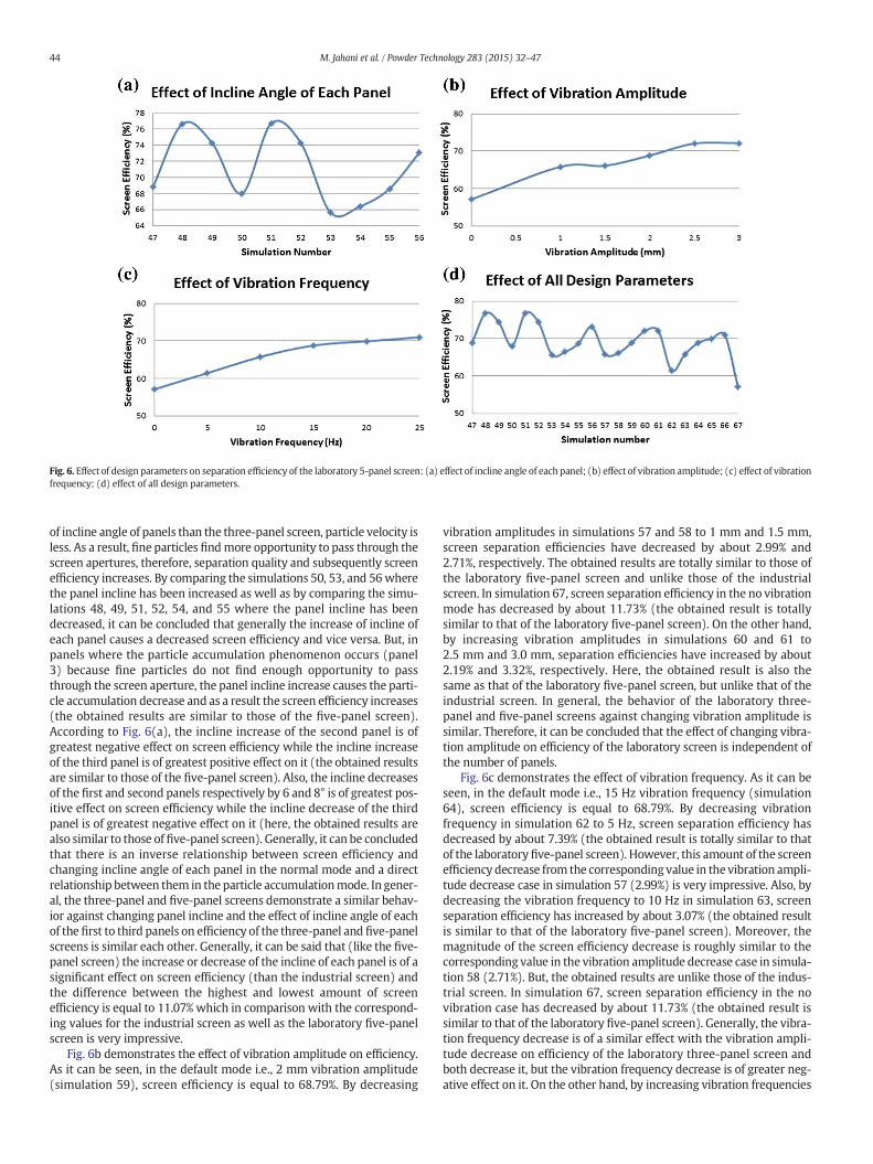
Fig. 6. Effect of design parameters on separation efficiency of the laboratory 5-panel screen: (a) effect of incline angle of each panel; (b) effect of vibration amplitude; (c) effect of vibrationfrequency; (d) effect of all design parameters.
44 M. Jahani et al. / Powder Technology 283 (2015) 32–47
of incline angle of panels than the three-panel screen, particle velocity isless. As a result, fine particles findmore opportunity to pass through thescreen apertures, therefore, separation quality and subsequently screenefficiency increases. By comparing the simulations 50, 53, and 56wherethe panel incline has been increased as well as by comparing the simu-lations 48, 49, 51, 52, 54, and 55 where the panel incline has beendecreased, it can be concluded that generally the increase of incline ofeach panel causes a decreased screen efficiency and vice versa. But, inpanels where the particle accumulation phenomenon occurs (panel3) because fine particles do not find enough opportunity to passthrough the screen aperture, the panel incline increase causes the parti-cle accumulation decrease and as a result the screen efficiency increases(the obtained results are similar to those of the five-panel screen).According to Fig. 6(a), the incline increase of the second panel is ofgreatest negative effect on screen efficiency while the incline increaseof the third panel is of greatest positive effect on it (the obtained resultsare similar to those of the five-panel screen). Also, the incline decreasesof the first and second panels respectively by 6 and 8° is of greatest pos-itive effect on screen efficiency while the incline decrease of the thirdpanel is of greatest negative effect on it (here, the obtained results arealso similar to those of five-panel screen). Generally, it can be concludedthat there is an inverse relationship between screen efficiency andchanging incline angle of each panel in the normal mode and a directrelationship between them in the particle accumulationmode. In gener-al, the three-panel and five-panel screens demonstrate a similar behav-ior against changing panel incline and the effect of incline angle of eachof the first to third panels on efficiency of the three-panel and five-panelscreens is similar each other. Generally, it can be said that (like the five-panel screen) the increase or decrease of the incline of each panel is of asignificant effect on screen efficiency (than the industrial screen) andthe difference between the highest and lowest amount of screenefficiency is equal to 11.07% which in comparison with the correspond-ing values for the industrial screen as well as the laboratory five-panelscreen is very impressive.
Fig. 6b demonstrates the effect of vibration amplitude on efficiency.As it can be seen, in the default mode i.e., 2 mm vibration amplitude(simulation 59), screen efficiency is equal to 68.79%. By decreasing
vibration amplitudes in simulations 57 and 58 to 1 mm and 1.5 mm,screen separation efficiencies have decreased by about 2.99% and2.71%, respectively. The obtained results are totally similar to those ofthe laboratory five-panel screen and unlike those of the industrialscreen. In simulation 67, screen separation efficiency in the no vibrationmode has decreased by about 11.73% (the obtained result is totallysimilar to that of the laboratory five-panel screen). On the other hand,by increasing vibration amplitudes in simulations 60 and 61 to2.5 mm and 3.0 mm, separation efficiencies have increased by about2.19% and 3.32%, respectively. Here, the obtained result is also thesame as that of the laboratory five-panel screen, but unlike that of theindustrial screen. In general, the behavior of the laboratory three-panel and five-panel screens against changing vibration amplitude issimilar. Therefore, it can be concluded that the effect of changing vibra-tion amplitude on efficiency of the laboratory screen is independent ofthe number of panels.
Fig. 6c demonstrates the effect of vibration frequency. As it can beseen, in the default mode i.e., 15 Hz vibration frequency (simulation64), screen efficiency is equal to 68.79%. By decreasing vibrationfrequency in simulation 62 to 5 Hz, screen separation efficiency hasdecreased by about 7.39% (the obtained result is totally similar to thatof the laboratoryfive-panel screen). However, this amount of the screenefficiency decrease from the corresponding value in the vibration ampli-tude decrease case in simulation 57 (2.99%) is very impressive. Also, bydecreasing the vibration frequency to 10 Hz in simulation 63, screenseparation efficiency has increased by about 3.07% (the obtained resultis similar to that of the laboratory five-panel screen). Moreover, themagnitude of the screen efficiency decrease is roughly similar to thecorresponding value in the vibration amplitude decrease case in simula-tion 58 (2.71%). But, the obtained results are unlike those of the indus-trial screen. In simulation 67, screen separation efficiency in the novibration case has decreased by about 11.73% (the obtained result issimilar to that of the laboratory five-panel screen). Generally, the vibra-tion frequency decrease is of a similar effect with the vibration ampli-tude decrease on efficiency of the laboratory three-panel screen andboth decrease it, but the vibration frequency decrease is of greater neg-ative effect on it. On the other hand, by increasing vibration frequencies

45M. Jahani et al. / Powder Technology 283 (2015) 32–47
to 20 Hz and 25 Hz in simulations 65 and 66, screen separation efficien-cies have increased by about 1.12% and 2.21%, respectively. Theseamounts of the screen efficiency increase are similar to the correspond-ing amounts in the vibration amplitude increase case in simulations 60and 61. Again, the obtained results are similar to those of the laboratoryfive-panel screen and contrary to those of the industrial screen. Gener-ally, the vibration frequency increase is of a similar effect with the vibra-tion amplitude increase on efficiency of the laboratory three-panelscreen and both increase it, but the vibration amplitude increase is ofgreater positive effect on it. The obtained result is unlike that of thelaboratory five-panel screen. But in general, it can be said that changingvibration frequency is of greater effect than vibration amplitude onefficiency of the laboratory three-panel screen (like the laboratoryfive-panel screen). In general, the behavior of the laboratory three-panel and five-panel screens against changing vibration frequency issimilar aswell. Therefore, it can be concluded that the effect of changingvibration frequency also on laboratory screen efficiency is independentof the number of panels.
Fig. 6d demonstrates the effect of all design parameters on separa-tion efficiency of the laboratory three-panel single-deck screen. As it
Fig. 7. Comparison between thepartition numbers of simulations 40, 45, 56, 60, and 65 and the rof 3mm; (b) the laboratory 5-panel screenwith vibration frequency of 25 Hz; (c) the laboratorywith vibration amplitude of 2.5 mm; (e) the laboratory 3-panel screen with vibration frequenc
can be seen, their effect on screen separation efficiency is almost thesame. But, the incline decrease of the first and second panels in simula-tions 48 and 51 is of greatest positive effect on separation efficiency andthe vibration frequency decrease in simulation 62 is of greatest negativeeffect.
The simulation results in this work demonstrate that the decreasesof vibration frequency and amplitude will result in a decreased efficien-cy for laboratory screens, this is however different from the conclusionsin the literature [4]. The reason for this is that in the previous studies inthe literature [4,27], particles were fed continuously which is not truefor a batch system! But when feeding particles all at once, the particleaccumulation phenomenon occurs sooner. Thus, here the simulationresults are not the same as in previous studies.
4.4. Validation
Since the DEM approach offers such strong advantages in modelingand understanding screening process, it is essential that both DEMsimulations and the DEM solver are validated properly and adequately.In general a comprehensive validation of DEM solver and simulations
esults ofDong's simulations [4]: (a) the laboratory 5-panel screenwith vibration amplitude3-panel screenwith the panel incline of 34, 22, and 14°; (d) the laboratory 3-panel screeny of 20 Hz.

46 M. Jahani et al. / Powder Technology 283 (2015) 32–47
is not feasible and inmost cases it can be done only partially. In order toensure the integrity of the application of the DEM techniques to commi-nution technology and other possible areas the quality of validationshould be improved and directed at the outputs being used in themodeling [46]. In this article, in order to validate the simulation results,a parameter named ‘partition number’ is defined as follows. The parti-tion number of different sized particles in the overflow is defined asthe ratio between the number of residue particles in the overflow tothat of fed particles [4]. To validate the obtained results and also theLIGGGHTS DEM solver, partition numbers of simulations conducted bythis software for the laboratory three-panel and five-panel screens arecomparedwith partition numbers of simulations doneunder the similarconditions by Dong et al. [4](Fig. 7). It is noteworthy to mention thathere in the partition number simulations particles are fed continuously.The high agreement between the results indicates their validity and alsothe validity of the DEM solver.
5. Conclusion
Our simulation studies indicate that DEM is now approaching thepoint where it can be used effectively as a tool for better understandingof banana screen operation and also their design and optimization.Unlike previous DEM-based researches related to banana screens, theauthors used DEM simulation results to express banana screen perfor-mance in terms of screen separation efficiency for laboratory screensand based on screening recovery for the industrial screen which isrecognized and comprehensible quantities for mineral processing engi-neers. Also in this article, for the first time the effect of screen designparameters on screening recovery of a full-industrial scale double-deck banana screen and on separation efficiency of laboratory scalethree-panel and five-panel single-deck banana screens was simulta-neously investigated and compared. Additionally, the effect of opera-tional parameters including increasing simulation time and changingfeed particle size distribution on screening recovery of the industrialdouble-deck banana screen were investigated.
In this article, in order to investigate the validity of the simulationresults, a parameter named ‘partition number’ was used. Comparingthe partition numbers of the simulations conducted by LIGGGHTS soft-ware for laboratory three-panel and five-panel banana screens with thepartition numbers of the conducted simulations under similar condi-tions by Dong et al. [4] demonstrated that there is very good agreementbetween them, indicating the validity of the simulation results and theDEM solver.
The simulation results demonstrated that industrial and laboratorybanana screens show a totally different behavior against changingdesign parameters.
Acknowledgment
The authors would like to thank the community of CFDEM project(2014) for giving important input and contributions to thedevelopmentof this open source project.
References
[1] G.W. Delaney, P.W. Cleary, M. Hilden, R.D. Morrison, Testing the validity of thespherical DEM model in simulating real granular screening processes, Chem. Eng.Sci. 68 (2012) 215–226.
[2] J. Li, C. Webb, S.S. Pandiella, G.M. Campbell, A numerical simulation of separation ofcrop seeds by screening—effect of particle bed depth, Trans. IChemE 80 (2002)109–117.
[3] J. Li, C. Webb, S.S. Pandiella, G.M. Campbell, Discrete particle motion on sieves—anumerical study using the DEM simulation, Powder Technol. 133 (2003)190–202.
[4] K.J. Dong, A.B. Yu, I. Brake, DEM simulation of particle flow on a multi-deck bananascreen, Miner. Eng. 22 (2009) 910–920.
[5] G.K.N.S. Subasinghe, W. Schaap, E.G. Kelly, Modelling the screening process: a prob-abilistic approach, Powder Technol. 59 (1989) 37–44.
[6] N. Standish, The kinetics of batch sieving, Powder Technol. 41 (1985) 57–67.
[7] J.W. Fernandez, P.W. Cleary, M.D. Sinnott, R.D. Morrison, Using SPHone-way coupledto DEM to model wet industrial banana screens, Miner. Eng. 24 (2011) 741–753.
[8] P.W. Cleary, M.D. Sinnott, R.D. Morrison, Separation performance of double deckbanana screens — part 1: flow and separation for different accelerations, Miner.Eng. 22 (2009) 1218–1229.
[9] P.W. Cleary, Large scale industrial DEMmodeling, Eng. Comput. 21 (2004) 169–204.[10] P.W. Cleary, M.D. Sinnott, R.D. Morrison, DEM prediction of particle flows in grind-
ing processes, Int. J. Numer. Methods Fluids 58 (2008) 319–353.[11] P.W. Cleary, Ball motion, axial segregation and power consumption in a full scale
two chamber cement mill, Miner. Eng. 22 (2009) 809–820.[12] J. Kozicki, F.V. Donzé, YADE-OPEN DEM: an open-source software using a dis-
crete element method to simulate granular material, Eng. Comput. 26 (2009)786–805.
[13] J. Chen, B. Huang, F. Chen, X. Shu, Application of discrete element method toSuperpave gyratory compaction, Road Mater. Pavement 13 (2012) 480–500.
[14] L. Zhang, S.F. Quigley, A.H.C. Chan, A fast scalable implementation of the two-dimensional triangular Discrete Element Method on a GPU platform, Adv. Eng.Softw. 60–61 (2013) 70–80.
[15] H. Kruggel-Emden, M. Sturm, S. Wirtz, V. Scherer, Selection of an appropriate timeintegration scheme for the discrete element method (DEM), Comput. Chem. Eng.32 (2008) 2263–2279.
[16] B. Nassauer, T. Liedke,M. Kuna, Polyhedral particles for the discrete element methodGeometry representation, contact detection and particle generation, Granul. Matter15 (2013) 85–93.
[17] A.O. Raji, J.F. Favier, Model for the deformation in agricultural and food particulatematerials under bulk compressive loading using discrete element method. I: theory,model development and validation, J. Food Eng. 64 (2004) 359–371.
[18] B. Nassauer, M. Kuna, Contact forces of polyhedral particles in discrete elementmethod, Granul. Matter 15 (2013) 349–355.
[19] R. Balevičius, A. Džiugys, R. Kačianauskas, A. Maknickas, K. Vislavičius, Investigationof performance of programming approaches and languages used for numericalsimulation of granular material by the discrete element method, Comput. Phys.Commun. 175 (2006) 404–415.
[20] G.W. Delaney, P.W. Cleary, R.D. Morrison, S. Cummins, B. Loveday, Predicting break-age and the evolution of rock size and shape distributions in Ag and SAGmills usingDEM, Miner. Eng. 50–51 (2013) 132–139.
[21] J.M. Ting, M. Khwaja, L.R. Meachum, J.D. Rowell, An ellipse-based discrete elementmodel for granular materials, Int. J. Numer. Anal. Methods Geomech. 17 (1993)603–623.
[22] I. Shmulevich, State of the art modeling of soil–tillage interaction using discreteelement method, Soil Tillage Res. 111 (2010) 41–53.
[23] P.W. Cleary, M.L. Sawley, DEMmodelling of industrial granular flows: 3D case stud-ies and the effect of particle shape on hopper discharge, Appl. Math. Model. 26(2002) 89–111.
[24] P.W. Cleary, Industrial particle flow modelling using discrete element method, Eng.Comput. 26 (2009) 698–743.
[25] P.W. Cleary, M.D. Sinnott, Assessing mixing characteristics of particle-mixing andgranulation devices, Particuology 6 (2008) 419–444.
[26] P.W. Cleary, DEM prediction of industrial and geophysical particle flows,Particuology 8 (2010) 106–118.
[27] K.J. Dong, A.B. Yu, Numerical simulation of the particle flow and sieving behaviouron sieve bend/low head screen combination, Miner. Eng. 31 (2012) 2–9.
[28] P.W. Cleary, M.D. Sinnott, R.D. Morrison, Separation performance of double deckbanana screens — part 2: quantitative predictions, Miner. Eng. 22 (2009)1230–1244.
[29] C. Goniva, C. Kloss, N.G. Deen, J.A.M. Kuipers, S. Pirker, Influence of rolling friction onsingle spout fluidized bed simulation, Particuology 10 (2012) 582–591.
[30] B. FrantzDale, S.J. Plimpton, M.S. Shephard, Software components for parallelmultiscale simulation: an example with LAMMPS, Eng. Comput. 26 (2010) 205–211.
[31] C. Kloss, C. Goniva, LIGGGHTS—Open Source Discrete Element Simulations ofGranular Materials Based on LAMMPS, 2, TMS (The Minerals, Metals & MaterialsSociety), 2011. 781–788
[32] S.J. Plimpton, J.D. Gale, Developing community codes for materials modeling, Curr.Opinion Solid State Mater. Sci. 17 (2013) 271–276
[33] C. Thornton, S.J. Cummins, P.W. Cleary, An investigation of the comparative behav-iour of alternative contact force models during elastic collisions, Powder Technol.210 (2011) 189–197
[34] LIGGGHTS, LAMMPS Improved for General Granular and Granular Heat TransferSimulationsRetrieved from http://www.cfdem.com2014
[35] C. Goniva, C. Kloss, A. Hager, S. Pirker, An open source CFD–DEM perspective,Proceedings of OpenFOAM Workshop Gothenburg, Sweden, 2010
[36] S.J. Plimpton, Fast Parallel Algorithms for short-range molecular dynamics, J.Comput. Phys. 117 (1995) 1–19
[37] LAMMPS, LAMMPS User Manual, Sandia National Laboratories, USA, 2014. (Re-trieved from http://lammps.sandia.gov/doc/Manual.html)
[38] GPL, GNU General Public LicenseRetrieved from http://www.gnu.org/licences/gpl.html2014
[39] V. Mechtcherine, A. Gram, K. Krenzer, J.-H. Schwabe, S. Shyshko, N. Roussel,Simulation of fresh concrete flow using Discrete Element Method (DEM): theoryand applications, Mater. Struct., RILEM Publications, 2013.http://dx.doi.org/10.1617/s11527-013-0084-7
[40] P.W. Cleary, R.D. Morrison, Particle methods for modelling in mineral processing,Int. J. Comput. Fluid Dyn. 23 (2009) 137–146
[41] S. Just, G. Toschkoff, A. Funke, D. Djuric, G. Scharrer, J. Khinast, K. Knop, P.Kleinebudde, Experimental analysis of tablet properties for discrete elementmodel-ing of an active coating process, AAPS PharmSciTech 14 (2013) 402–411.

47M. Jahani et al. / Powder Technology 283 (2015) 32–47
[42] R. Chand, M.A. Khaskheli, A. Qadir, B. Ge, Q. Shi, Discrete particle simulation of radialsegregation in horizontally rotating drum: effects of drum-length and non-rotatingend-plates, Physica A 391 (2012) 4590–4596.
[43] W. McBride, P.W. Cleary, An investigation and optimization of the ‘OLDS’elevator using Discrete Element Modeling, Powder Technol. 193 (2009)216–234.
[44] C. Kloss, C. Goniva, G. Aichinger, S. Pirker, Comprehensive DEM–DPM–CFDsimulations—model synthesis, experimental validation and scalability,
Seventh International Conference on CFD in the Minerals and Process Indus-tries CSIRO, Melbourne, Australia, 2009.
[45] M. Varga, C. Goniva, K. Adam, E. Badisch, Combined experimental and numericalapproach for wear prediction in feed pipes, Tribol. Int. 65 (2013) 200–206.
[46] N.S. Weerasekara, M.S. Powell, P.W. Cleary, L.M. Tavares, M. Evertsson, R.D.Morrison, J. Quist, R.M. Carvalho, The contribution of DEM to the science of commi-nution, Powder Technol. 248 (2013) 3–24.


![Jahan e Hairat [PdfStuff.blogspot.com]](https://img.pdfslide.net/doc/110x75/55cf9687550346d0338c132f/jahan-e-hairat-pdfstuffblogspotcom.jpg)


![Jahan Miyan 2jang [Www.ketabesabz.com]](https://img.pdfslide.net/doc/110x75/563dbb4b550346aa9aabf649/jahan-miyan-2jang-wwwketabesabzcom.jpg)