Embed Size (px)
Citation preview
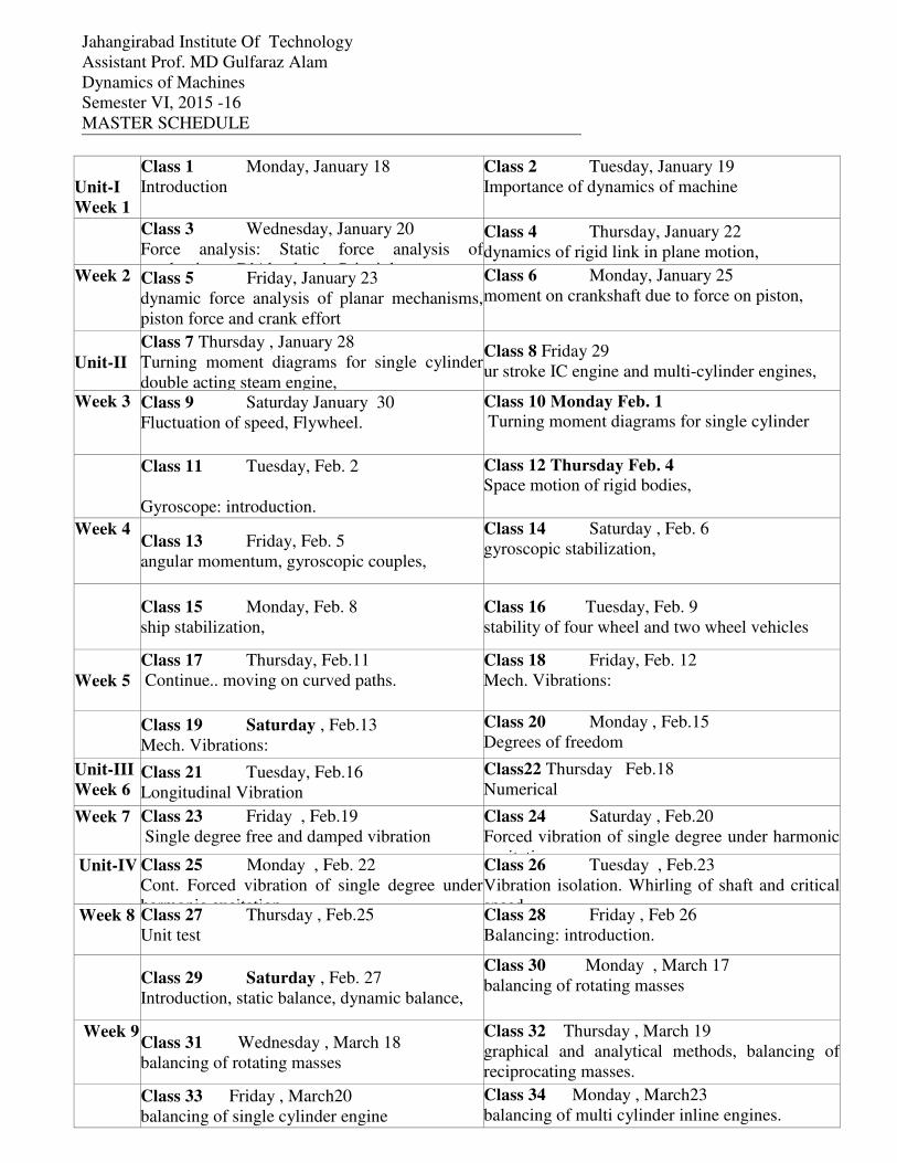
Jahangirabad Institute Of Technology
Assistant Prof. MD Gulfaraz Alam
Dynamics of Machines
Semester VI, 2015 -16
MASTER SCHEDULE
Unit-I
Week 1
Class 1 Monday, January 18
Introduction
Class 2 Tuesday, January 19
Importance of dynamics of machine
Class 3 Wednesday, January 20
Force analysis: Static force analysis of
mechanisms, D’Alembert’s Principle,
Class 4 Thursday, January 22
dynamics of rigid link in plane motion,
Week 2
Class 5 Friday, January 23
dynamic force analysis of planar mechanisms,
piston force and crank effort
Class 6 Monday, January 25
moment on crankshaft due to force on piston,
Unit-II
Class 7 Thursday , January 28
Turning moment diagrams for single cylinder
double acting steam engine,
Class 8 Friday 29
ur stroke IC engine and multi-cylinder engines,
Week 3 Class 9 Saturday January 30
Fluctuation of speed, Flywheel.
Class 10 Monday Feb. 1 Turning moment diagrams for single cylinder
Class 11 Tuesday, Feb. 2
Gyroscope: introduction.
Class 12 Thursday Feb. 4
Space motion of rigid bodies,
Week 4 Class 13 Friday, Feb. 5
angular momentum, gyroscopic couples,
Class 14 Saturday , Feb. 6
gyroscopic stabilization,
Class 15 Monday, Feb. 8
ship stabilization,
Class 16 Tuesday, Feb. 9
stability of four wheel and two wheel vehicles
Week 5
Class 17 Thursday, Feb.11
Continue.. moving on curved paths.
Class 18 Friday, Feb. 12
Mech. Vibrations:
Class 19 Saturday , Feb.13
Mech. Vibrations:
Class 20 Monday , Feb.15
Degrees of freedom
Unit-III
Week 6 Class 21 Tuesday, Feb.16
Longitudinal Vibration
Class22 Thursday Feb.18
Numerical
Week 7 Class 23 Friday , Feb.19
Single degree free and damped vibration
Class 24 Saturday , Feb.20
Forced vibration of single degree under harmonic
excitation Unit-IV Class 25 Monday , Feb. 22
Cont. Forced vibration of single degree under
harmonic excitation
Class 26 Tuesday , Feb.23
Vibration isolation. Whirling of shaft and critical
speed. Week 8 Class 27 Thursday , Feb.25
Unit test
Class 28 Friday , Feb 26
Balancing: introduction.
Class 29 Saturday , Feb. 27
Introduction, static balance, dynamic balance,
Class 30 Monday , March 17
balancing of rotating masses
Week 9 Class 31 Wednesday , March 18
balancing of rotating masses
Class 32 Thursday , March 19
graphical and analytical methods, balancing of
reciprocating masses.
Class 33 Friday , March20
balancing of single cylinder engine
Class 34 Monday , March23
balancing of multi cylinder inline engines.

Week 10 Class 35 Tuesday , March 24
Numerical
Class 36 Wednesday , March 2
Unit test 2
Class 37 Thursday , March26
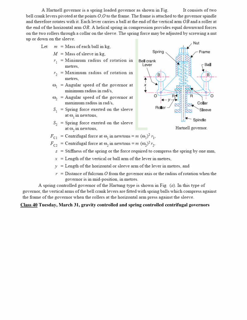
Introduction, types of governors
Class 38 Friday , March 27
characteristics of centrifugal governors Class 39 Monday , March 30
Gravity controlled and spring controlled
centrifugal governors
Class 40 Tuesday ,March 31
Gravity controlled and spring controlled
centrifugal governors
Class 41 Wednesday ,April 1
hunting of centrifugal governors,
Class 42 Friday , April 3
inertia governors
Class 43 Monday ,April 6
Effort and Power of governor,
Class 44 Tuesday ,April 7
Controlling force diagrams for Porter governor
Class 45 Wednesday April 8
And spring controlled governors.
Class 46 Thursday April 9
Numerical
Class 47 Friday , April 10
Brakes and dynamometers:
Class 48 Monday ,April 13
Introduction, Law of friction
Class 49 Tuesday , April 14
and types of lubrication,
Class 50 Wednesday , April 15
types of brakes,
Class 51 Thursday ,April 16
effect of braking on rear
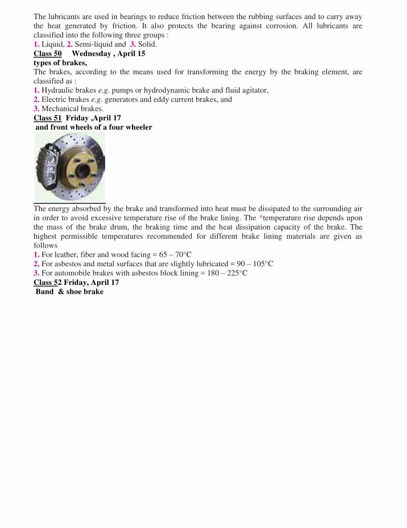
Class 52 Friday ,April 17
and front wheels of a four wheeler
Class 53 Monday ,April 20
dynamometers,
Class 54 Tuesday ,April 21
belt transmission dynamometer,
Class 55 Wednesday ,April 22
torsion dynamometer,
Class 56 Thursday , April 23
hydraulic dynamometer
Class 57 Friday ,April 24
Numerical
Details are found in the following sections: General Information, Class Schedule, and Project
Schedule.
GENERAL INFORMATION
Teaching Staff: MD GULFARAZ ALAM
Assist Prof, JIT ME, [email protected]
Course Web Site:
Class Meetings:
JIT Room 205
GOALS: The main goal is to contribute to the further development of the Science and Technology of
dynamics of machines, which is of fundamental importance for the future
Dimensional and integrate resources. Usually required to consider physical, human and
financial resources at high efficiency and low cost, yet considering the possibility of
continuous further improvement;
Make proper use of math and statistics to model production systems during decision making
process;
Design, implement and refine products, services, processes and systems taking in consideration
that constraints and particularities of the related communities;
Course Objectives:
To understand the method of static force analysis and dynamic force analysis of Mechanisms
To study the undesirable effects of unbalance in rotors and engines.
To understand the concept of vibratory systems and their analysis
To understand the principles of governors and gyroscopes.
Classes and Topics
Class 1 Introduction
Monday, January 18 This subject is a continuation of statics and dynamics, which is taken by students in their freshman or
sophomore years. In kinematics and dynamics of machines and mechanisms, however, the emphasis
shifts from studying general concepts with illustrative examples to developing methods and
performing analyses of real designs. This shift in emphasis is important, since it entails dealing with
complex objects and utilizing different tools to analyze these objects
Class 2 Class 2 Tuesday, January 19
Importance of dynamics of machine
The design process starts with meeting the functional requirements of the product. The basic one in
this case is the proper opening, dwelling, and closing of the valve as a function of time. To achieve
this objective, a corresponding cam profile producing the needed follower motion should be found.
The rocker arm, being a lever, serves as a displacement amplifier/reducer. The timing of opening,
dwelling, and closing is controlled by the speed of the camshaft. The function of the spring is to keep
the roller always in contact with the cam.
Class 3 Thursday, January 22
Dynamics of rigid link in plane motion,
• Reduced delivery times • Reduced set-up costs
• Reduced set-up times
• Reduced transportation costs • Reduced investment in stock • Reduction in batch sizes • Improved quality
• Improved reliability Technological
In order to understand a firm’s technological competitiveness, a periodic technology assess-
ment needs to be performed to chart the deterio-ration of technology and to benchmark a
firm’srelative position against a competitor.
Class 4 Wednesday, January 20
Force analysis: Static force analysis of
A force is characterized by its magnitude and direction, and thus is a vector. In an (x, y)-plane the
force vector, F, can be represented in different forms
F = [Fx, Fy]
= F [cosα, sinα]T = F (i cosα + j sinα) where Fx, Fy are the x- and y-components of the vector (Figure 3.1), α indicates force direction (positive α is measured counterclockwise), and i and j are the unit vectors directed along the x- and y-
axis, correspondingly. A moment of the force F with respect to a point A is a vector found as a cross-
product of two vectors: M = rA × F
Class 5, Thursday, January 22
Dynamics of rigid link in plane motion,
It consists of four rigid bodies (called bars or links), each attached to two others by single joints or
pivots to form closed loop. Four-bars are simple mechanisms common in mechanical engineering
machine design and fall under the study of kinematics. Dynamic Analysis of Reciprocating engines.
Inertia force and torque analysis by neglecting weight of connecting rod.
Velocity and acceleration of piston.
Angular velocity and Angular acceleration of connecting rod.
Force and Torque Analysis in reciprocating engine neglecting the weight of connecting
rod. Equivalent Dynamical System
Determination of two masses of equivalent dynamical system.
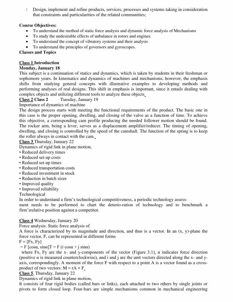
Class 6 Monday, January 25
moment on crankshaft due to force on piston,
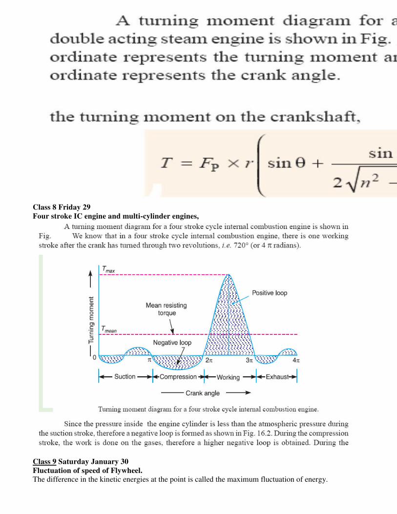
Class 7 Thursday , January 28
Turning moment diagrams for single cylinder double acting steam engine.
The turning moment diagram is graphical representation of the turning moment or crank effort for
various positions of crank.
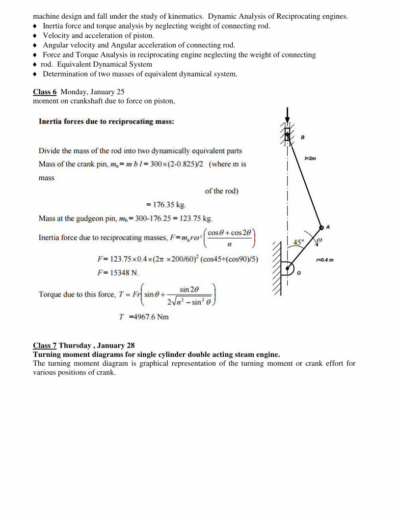
Class 8 Friday 29
Four stroke IC engine and multi-cylinder engines,
Class 9 Saturday January 30
Fluctuation of speed of Flywheel.
The difference in the kinetic energies at the point is called the maximum fluctuation of energy.
Class 10 Monday Feb. 1
Turning moment diagrams for single cylinder
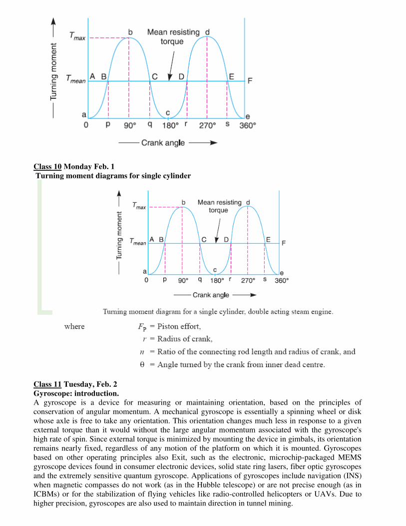
Class 11 Tuesday, Feb. 2
Gyroscope: introduction.
A gyroscope is a device for measuring or maintaining orientation, based on the principles of
conservation of angular momentum. A mechanical gyroscope is essentially a spinning wheel or disk
whose axle is free to take any orientation. This orientation changes much less in response to a given
external torque than it would without the large angular momentum associated with the gyroscope's
high rate of spin. Since external torque is minimized by mounting the device in gimbals, its orientation
remains nearly fixed, regardless of any motion of the platform on which it is mounted. Gyroscopes
based on other operating principles also Exit, such as the electronic, microchip-packaged MEMS
gyroscope devices found in consumer electronic devices, solid state ring lasers, fiber optic gyroscopes
and the extremely sensitive quantum gyroscope. Applications of gyroscopes include navigation (INS)
when magnetic compasses do not work (as in the Hubble telescope) or are not precise enough (as in
ICBMs) or for the stabilization of flying vehicles like radio-controlled helicopters or UAVs. Due to
higher precision, gyroscopes are also used to maintain direction in tunnel mining.
Class 12 Thursday Feb. 4
Space motion of rigid bodies,
Diagram of a gyro wheel. Reaction arrows about the output axis (blue) correspond to forces applied
about the input axis (green), and vice versa. Within mechanical systems or devices, a conventional
gyroscope is a mechanism comprising a rotor journal led to spin about one axis, the journals of the
rotor being mounted in an inner gimbals or ring, the inner gimbals is journal led for oscillation in an
outer gimbals which is journal led in another gimbals. So basically there are three gimbals.
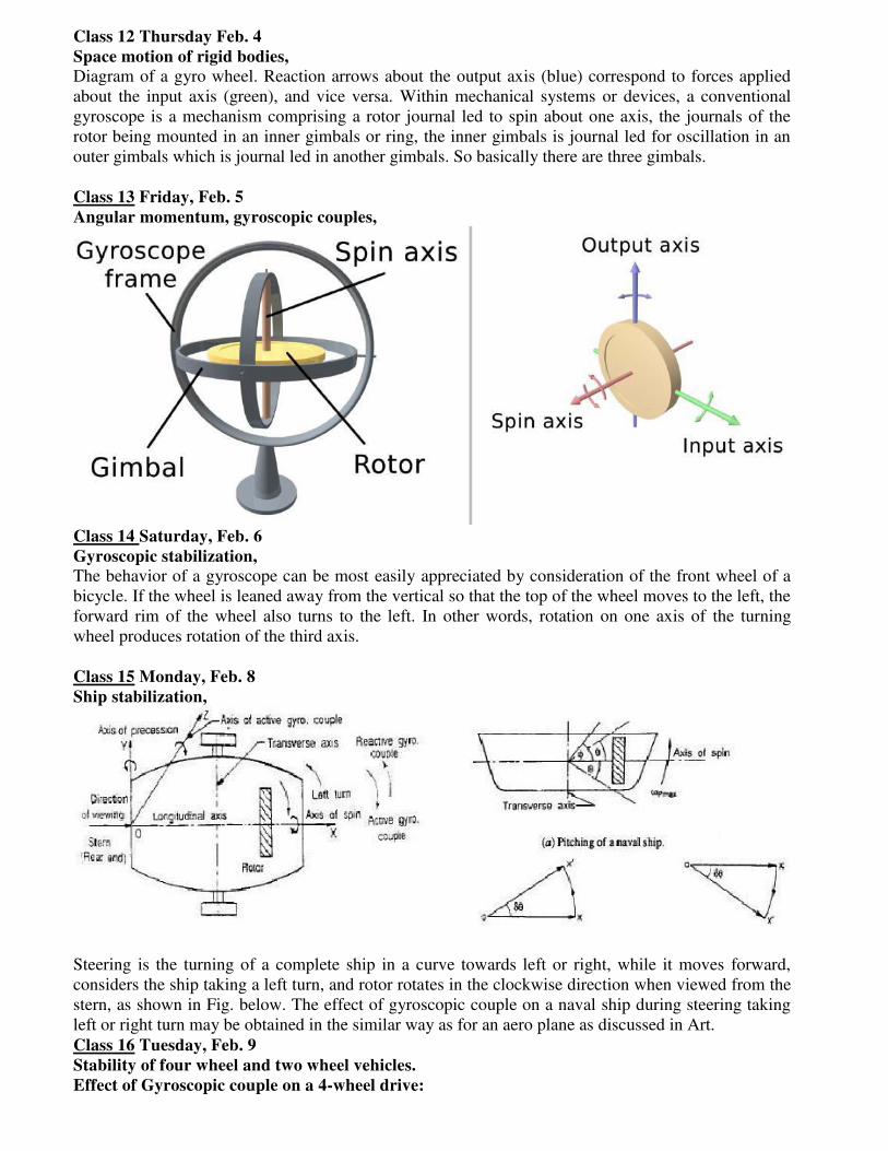
Class 13 Friday, Feb. 5
Angular momentum, gyroscopic couples,
Class 14 Saturday, Feb. 6
Gyroscopic stabilization,
The behavior of a gyroscope can be most easily appreciated by consideration of the front wheel of a
bicycle. If the wheel is leaned away from the vertical so that the top of the wheel moves to the left, the
forward rim of the wheel also turns to the left. In other words, rotation on one axis of the turning
wheel produces rotation of the third axis.
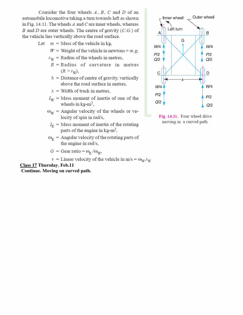
Class 15 Monday, Feb. 8
Ship stabilization,
Steering is the turning of a complete ship in a curve towards left or right, while it moves forward,
considers the ship taking a left turn, and rotor rotates in the clockwise direction when viewed from the
stern, as shown in Fig. below. The effect of gyroscopic couple on a naval ship during steering taking
left or right turn may be obtained in the similar way as for an aero plane as discussed in Art.
Class 16 Tuesday, Feb. 9
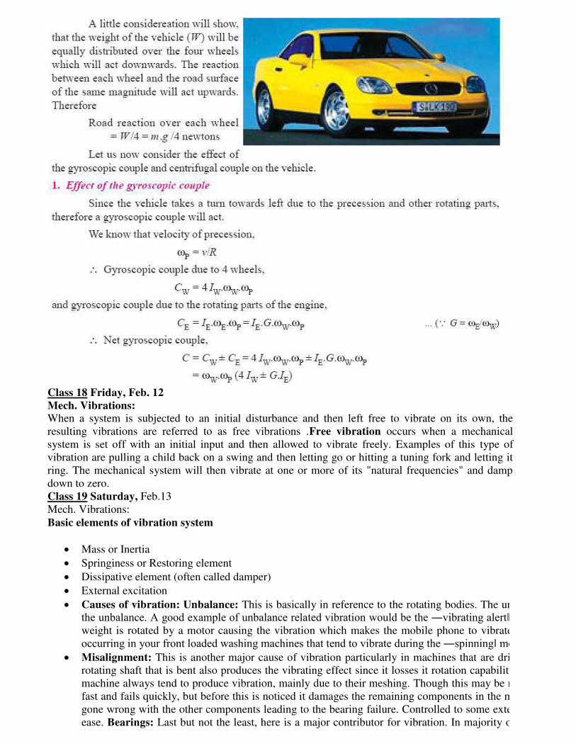
Stability of four wheel and two wheel vehicles.
Effect of Gyroscopic couple on a 4-wheel drive:
Class 17 Thursday, Feb.11
Continue. Moving on curved path.
Class 18 Friday, Feb. 12
Mech. Vibrations:
When a system is subjected to an initial disturbance and then left free to vibrate on its own, the
resulting vibrations are referred to as free vibrations .Free vibration occurs when a mechanical
system is set off with an initial input and then allowed to vibrate freely. Examples of this type of
vibration are pulling a child back on a swing and then letting go or hitting a tuning fork and letting it
ring. The mechanical system will then vibrate at one or more of its "natural frequencies" and damp
down to zero.
Class 19 Saturday, Feb.13
Mech. Vibrations:
Basic elements of vibration system
Mass or Inertia
Springiness or Restoring element
Dissipative element (often called damper)
External excitation
Causes of vibration: Unbalance: This is basically in reference to the rotating bodies. The une
the unbalance. A good example of unbalance related vibration would be the ―vibrating alert‖ in our mobile phones. Here a smalweight is rotated by a motor causing the vibration which makes the mobile phone to vibrate.
occurring in your front loaded washing machines that tend to vibrate during the ―spinning‖ mode. Misalignment: This is another major cause of vibration particularly in machines that are drive
rotating shaft that is bent also produces the vibrating effect since it losses it rotation capability
machine always tend to produce vibration, mainly due to their meshing. Though this may be ma
fast and fails quickly, but before this is noticed it damages the remaining components in the mac
gone wrong with the other components leading to the bearing failure. Controlled to some extent,
ease. Bearings: Last but not the least, here is a major contributor for vibration. In majority of
propagates to the rest of the members of the
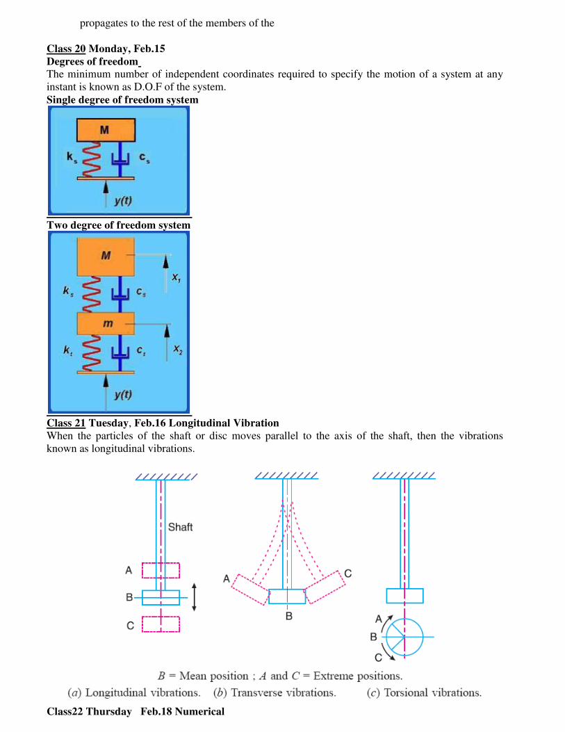
Class 20 Monday, Feb.15
Degrees of freedom
The minimum number of independent coordinates required to specify the motion of a system at any
instant is known as D.O.F of the system.
Single degree of freedom system
Two degree of freedom system
Class 21 Tuesday, Feb.16 Longitudinal Vibration
When the particles of the shaft or disc moves parallel to the axis of the shaft, then the vibrations
known as longitudinal vibrations.
Class22 Thursday Feb.18 Numerical
Solve the numerical relative to above theory.
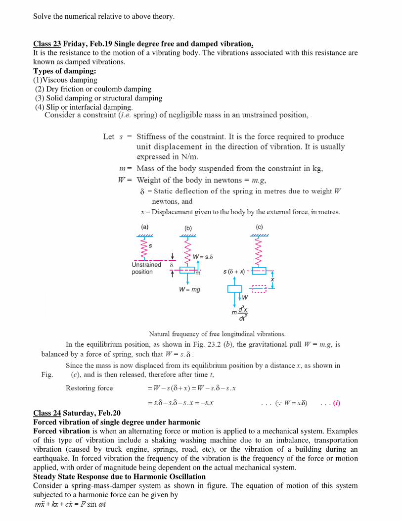
Class 23 Friday, Feb.19 Single degree free and damped vibration.
It is the resistance to the motion of a vibrating body. The vibrations associated with this resistance are
known as damped vibrations.
Types of damping:
(1)Viscous damping
(2) Dry friction or coulomb damping
(3) Solid damping or structural damping
(4) Slip or interfacial damping.
Class 24 Saturday, Feb.20
Forced vibration of single degree under harmonic
Forced vibration is when an alternating force or motion is applied to a mechanical system. Examples
of this type of vibration include a shaking washing machine due to an imbalance, transportation
vibration (caused by truck engine, springs, road, etc), or the vibration of a building during an
earthquake. In forced vibration the frequency of the vibration is the frequency of the force or motion
applied, with order of magnitude being dependent on the actual mechanical system.
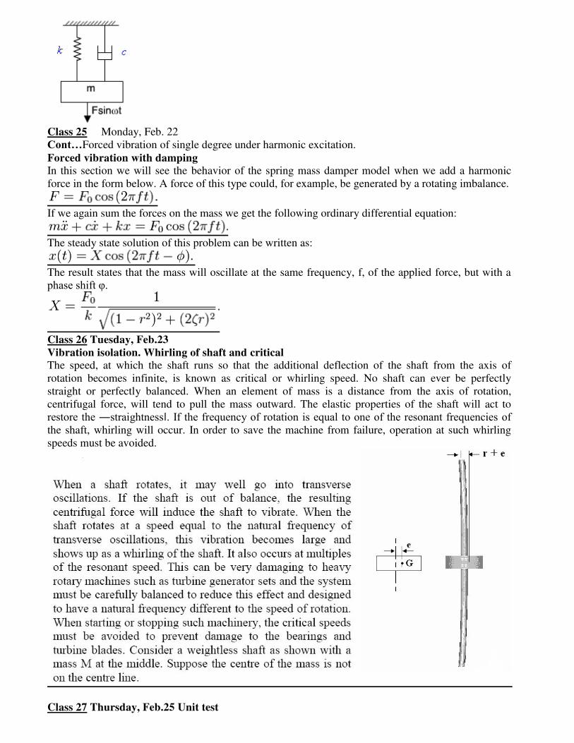
Steady State Response due to Harmonic Oscillation
Consider a spring-mass-damper system as shown in figure. The equation of motion of this system
subjected to a harmonic force can be given by
Class 25 Monday, Feb. 22
Cont…Forced vibration of single degree under harmonic excitation.
Forced vibration with damping
In this section we will see the behavior of the spring mass damper model when we add a harmonic
force in the form below. A force of this type could, for example, be generated by a rotating imbalance.
If we again sum the forces on the mass we get the following ordinary differential equation:
The steady state solution of this problem can be written as:
The result states that the mass will oscillate at the same frequency, f, of the applied force, but with a
phase shift φ.
Class 26 Tuesday, Feb.23
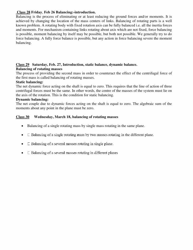
Vibration isolation. Whirling of shaft and critical
The speed, at which the shaft runs so that the additional deflection of the shaft from the axis of
rotation becomes infinite, is known as critical or whirling speed. No shaft can ever be perfectly
straight or perfectly balanced. When an element of mass is a distance from the axis of rotation,
centrifugal force, will tend to pull the mass outward. The elastic properties of the shaft will act to
restore the ―straightness‖. If the frequency of rotation is equal to one of the resonant frequencies of the shaft, whirling will occur. In order to save the machine from failure, operation at such whirling
speeds must be avoided.
Class 27 Thursday, Feb.25 Unit test
Class 28 Friday, Feb 26 Balancing:-introduction.
Balancing is the process of eliminating or at least reducing the ground forces and/or moments. It is
achieved by changing the location of the mass centers of links. Balancing of rotating parts is a well
known problem. A rotating body with fixed rotation axis can be fully balanced i.e. all the inertia forces
and moments. For mechanism containing links rotating about axis which are not fixed, force balancing
is possible, moment balancing by itself may be possible, but both not possible. We generally try to do
force balancing. A fully force balance is possible, but any action in force balancing severe the moment
balancing.
Class 29 Saturday, Feb. 27, Introduction, static balance, dynamic balance.
Balancing of rotating masses
The process of providing the second mass in order to counteract the effect of the centrifugal force of
the first mass is called balancing of rotating masses.
Static balancing:
The net dynamic force acting on the shaft is equal to zero. This requires that the line of action of three
centrifugal forces must be the same. In other words, the centre of the masses of the system must lie on
the axis of the rotation. This is the condition for static balancing.
Dynamic balancing:
The net couple due to dynamic forces acting on the shaft is equal to zero. The algebraic sum of the
moments about any point in the plane must be zero.
Class 30 Wednesday, March 18, balancing of rotating masses
Balancing of a single rotating mass by single mass rotating in the same plane.
n the different plane.
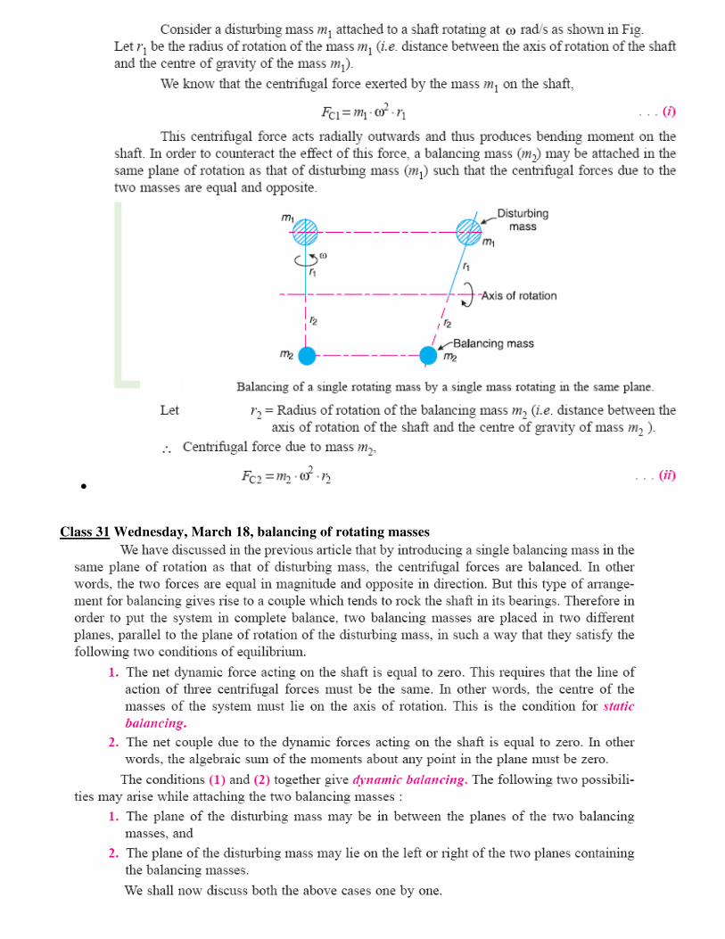
Class 31 Wednesday, March 18, balancing of rotating masses
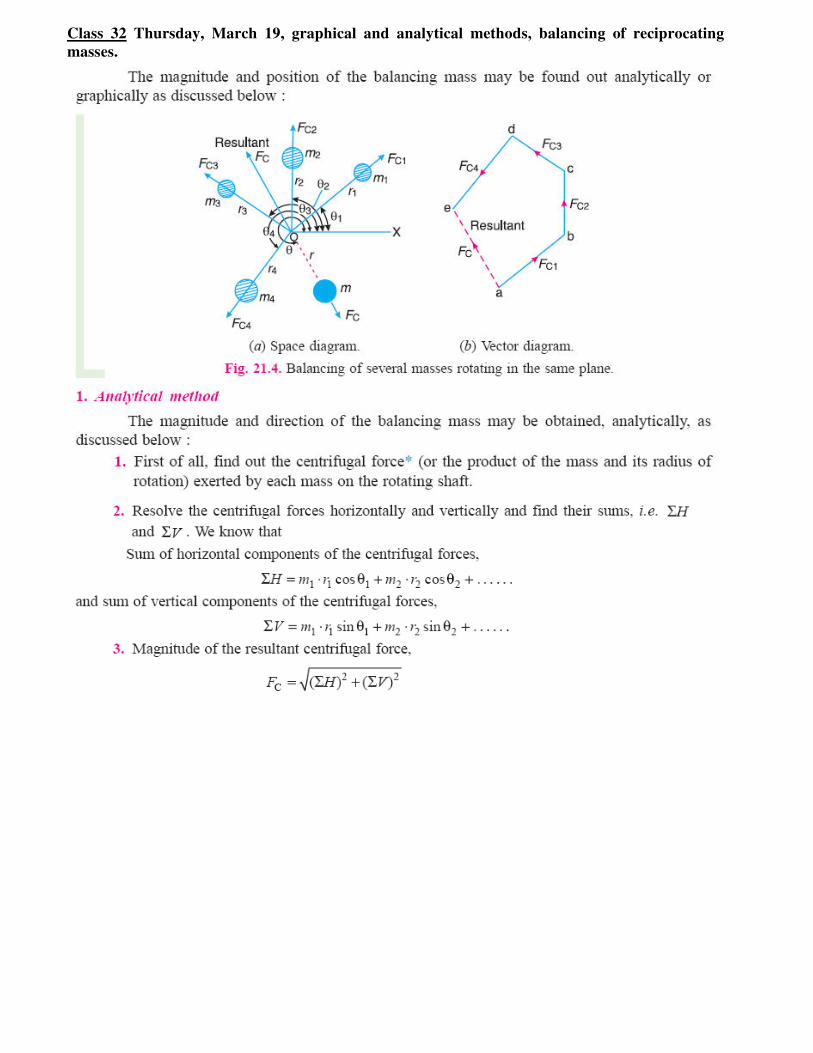
Class 32 Thursday, March 19, graphical and analytical methods, balancing of reciprocating
masses.
Class 33 Friday, March20
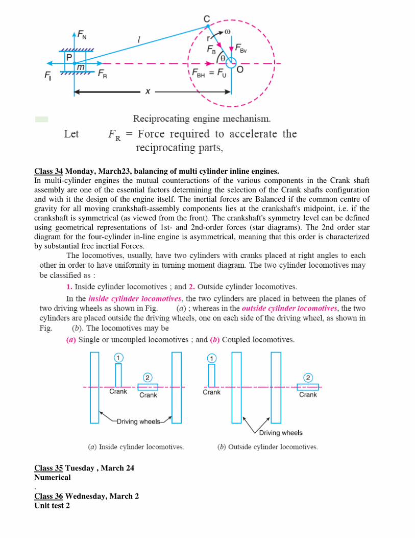
Balancing of single cylinder engine
A single cylinder engine produces three main vibrations. In describing them we will assume that the
cylinder is vertical. Firstly, in an engine with no balancing counterweights, there would be an
enormous vibration produced by the change in momentum of the piston, gudgeon pin, connecting rod
and crankshaft once every revolution. Nearly all single-cylinder crankshafts incorporate balancing
weights to reduce this. While these weights can balance the crankshaft completely, they cannot
completely balance the motion of the piston, for two reasons. The first reason is that the balancing
weights have horizontal motion as well as vertical motion, so balancing the purely vertical motion of
the piston by a crankshaft weight adds a horizontal vibration. The second reason is that, considering
now the vertical motion only, the smaller piston end of the connecting rod (little end) is closer to the
larger crankshaft end (big end) of the connecting rod in mid-stroke than it is at the top or bottom of the
stroke, because of the connecting rod's angle. So during the 180° rotation from mid-stroke through
top-dead-center and back to mid-stroke the minor contribution to the piston's up/down movement from
the connecting rod's change of angle has the same direction as the major contribution to the piston's
up/down movement from the up/down movement of the crank pin.
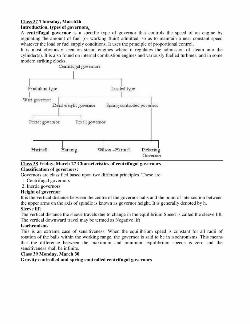
Class 34 Monday, March23, balancing of multi cylinder inline engines.
In multi-cylinder engines the mutual counteractions of the various components in the Crank shaft
assembly are one of the essential factors determining the selection of the Crank shafts configuration
and with it the design of the engine itself. The inertial forces are Balanced if the common centre of
gravity for all moving crankshaft-assembly components lies at the crankshaft's midpoint, i.e. if the
crankshaft is symmetrical (as viewed from the front). The crankshaft's symmetry level can be defined
using geometrical representations of 1st- and 2nd-order forces (star diagrams). The 2nd order star
diagram for the four-cylinder in-line engine is asymmetrical, meaning that this order is characterized
by substantial free inertial Forces.
Class 35 Tuesday , March 24
Numerical
.
Class 36 Wednesday, March 2
Unit test 2
Class 37 Thursday, March26
Introduction, types of governors.
A centrifugal governor is a specific type of governor that controls the speed of an engine by
regulating the amount of fuel (or working fluid) admitted, so as to maintain a near constant speed
whatever the load or fuel supply conditions. It uses the principle of proportional control.
It is most obviously seen on steam engines where it regulates the admission of steam into the
cylinder(s). It is also found on internal combustion engines and variously fuelled turbines, and in some
modern striking clocks.
Class 38 Friday, March 27 Characteristics of centrifugal governors
Classification of governors:
Governors are classified based upon two different principles. These are:
1. Centrifugal governors
2. Inertia governors
Height of governor
It is the vertical distance between the centre of the governor halls and the point of intersection between
the upper arms on the axis of spindle is known as governor height. It is generally denoted by h.
Sleeve lift
The vertical distance the sleeve travels due to change in the equilibrium Speed is called the sleeve lift.
The vertical downward travel may be termed as Negative lift
Isochronisms
This is an extreme case of sensitiveness. When the equilibrium speed is constant for all radii of
rotation of the balls within the working range, the governor is said to be in isochronisms. This means
that the difference between the maximum and minimum equilibrium speeds is zero and the
sensitiveness shall be infinite.
Class 39 Monday, March 30
Gravity controlled and spring controlled centrifugal governors
Class 40 Tuesday, March 31, gravity controlled and spring controlled centrifugal governors
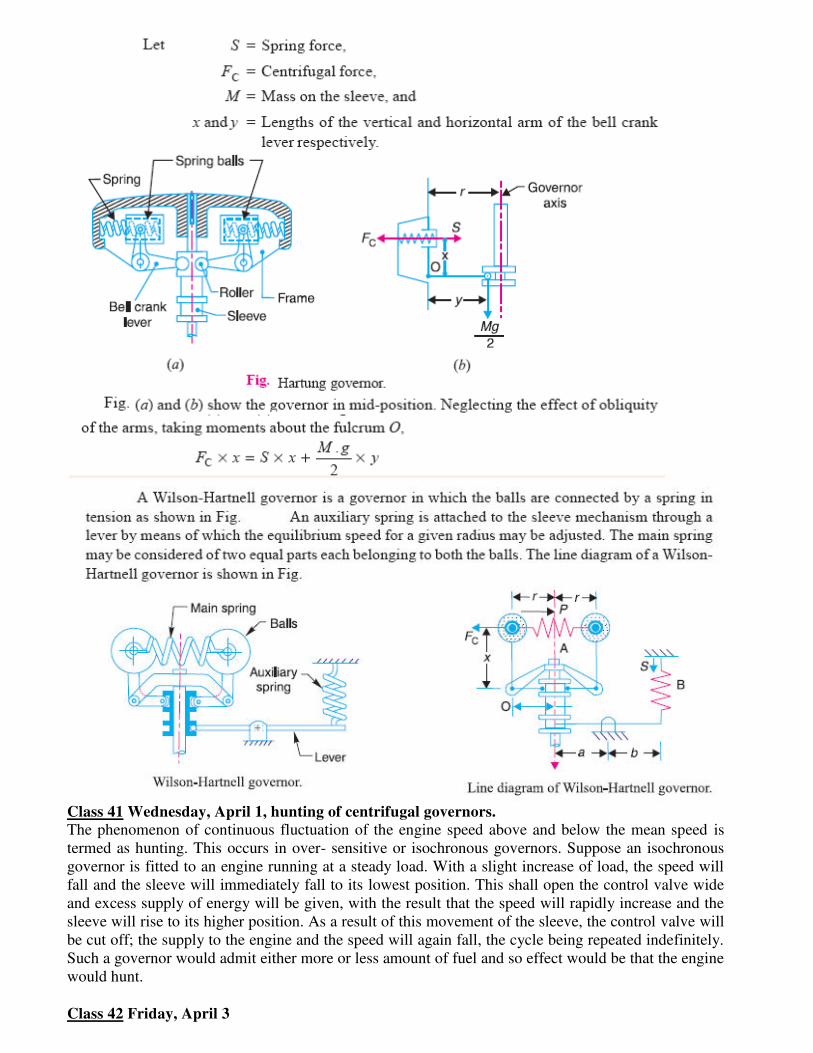
Class 41 Wednesday, April 1, hunting of centrifugal governors.
The phenomenon of continuous fluctuation of the engine speed above and below the mean speed is
termed as hunting. This occurs in over- sensitive or isochronous governors. Suppose an isochronous
governor is fitted to an engine running at a steady load. With a slight increase of load, the speed will
fall and the sleeve will immediately fall to its lowest position. This shall open the control valve wide
and excess supply of energy will be given, with the result that the speed will rapidly increase and the
sleeve will rise to its higher position. As a result of this movement of the sleeve, the control valve will
be cut off; the supply to the engine and the speed will again fall, the cycle being repeated indefinitely.
Such a governor would admit either more or less amount of fuel and so effect would be that the engine
would hunt.
Class 42 Friday, April 3
Inertia governors
Class 43 Monday, April 6
Effort and Power of governor,
Class 44 Tuesday, April 7
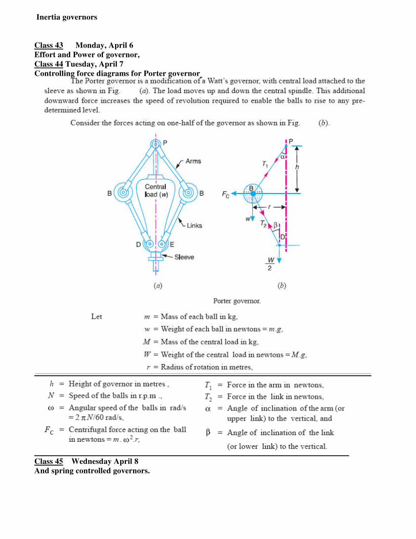
Controlling force diagrams for Porter governor
Class 45 Wednesday April 8
And spring controlled governors.
Class 46 Thursday April 9
Numerical
Class 47 Friday, April 10
Brakes and dynamometers:
A brake is a device by means of which artificial frictional resistance is applied to a moving machine
member, in order to retard or stop the motion of a machine. In the process of performing this function,
the brake absorbs either kinetic energy of the moving member or potential energy given up by objects
being lowered by hoists, elevators etc. The energy absorbed by brakes is dissipated in the form of heat.
This heat is dissipated in the surrounding air (or water which is circulated through the passages in the
brake drum) so that excessive heating of the brake lining does not take place. The design or capacity
of a brake depends upon thefollowing factors :
Class 48 Monday ,April 13
Introduction, Law of friction
In order to determine the coefficient of friction for well lubricated full journal bearings, the following
empirical relation established by McKee based on the experimental data, may be used.
Class 49 Tuesday, April 14
And types of lubrication,
The lubricants are used in bearings to reduce friction between the rubbing surfaces and to carry away
the heat generated by friction. It also protects the bearing against corrosion. All lubricants are
classified into the following three groups :
1. Liquid, 2. Semi-liquid and 3. Solid.
Class 50 Wednesday , April 15
types of brakes,
The brakes, according to the means used for transforming the energy by the braking element, are
classified as :
1. Hydraulic brakes e.g. pumps or hydrodynamic brake and fluid agitator,
2. Electric brakes e.g. generators and eddy current brakes, and
3. Mechanical brakes.
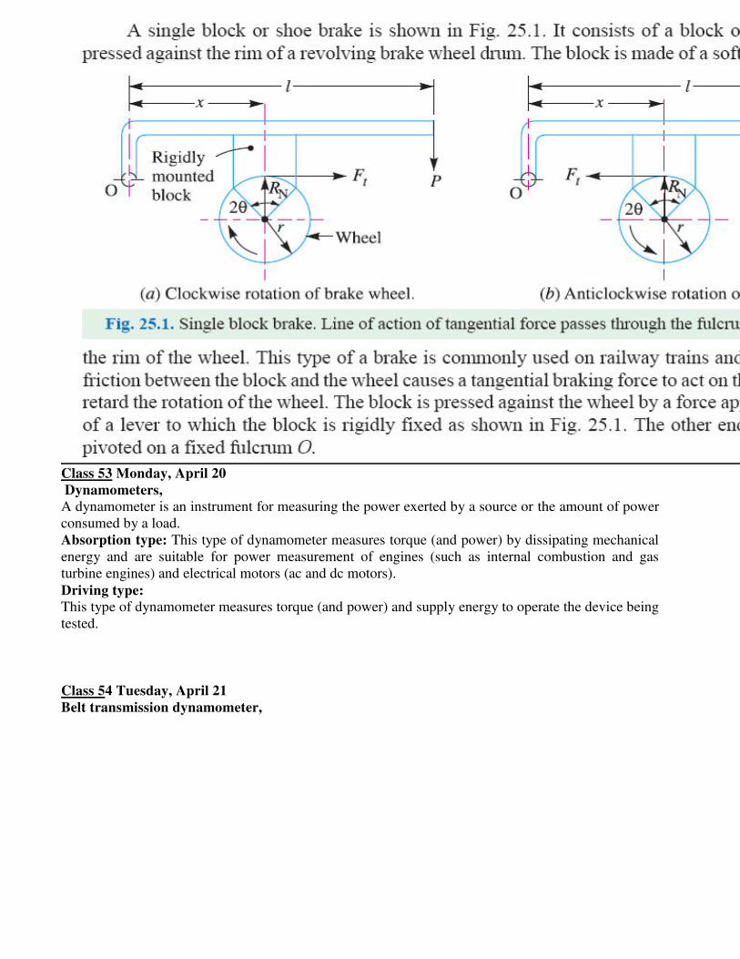
Class 51 Friday ,April 17
and front wheels of a four wheeler
The energy absorbed by the brake and transformed into heat must be dissipated to the surrounding air
in order to avoid excessive temperature rise of the brake lining. The *temperature rise depends upon
the mass of the brake drum, the braking time and the heat dissipation capacity of the brake. The
highest permissible temperatures recommended for different brake lining materials are given as
follows
1. For leather, fiber and wood facing = 65 – 70°C
2. For asbestos and metal surfaces that are slightly lubricated = 90 – 105°C
3. For automobile brakes with asbestos block lining = 180 – 225°C
Class 52 Friday, April 17
Band & shoe brake
Class 53 Monday, April 20
Dynamometers,
A dynamometer is an instrument for measuring the power exerted by a source or the amount of power
consumed by a load.
Absorption type: This type of dynamometer measures torque (and power) by dissipating mechanical
energy and are suitable for power measurement of engines (such as internal combustion and gas
turbine engines) and electrical motors (ac and dc motors).
Driving type:
This type of dynamometer measures torque (and power) and supply energy to operate the device being
tested.
Class 54 Tuesday, April 21
Belt transmission dynamometer,
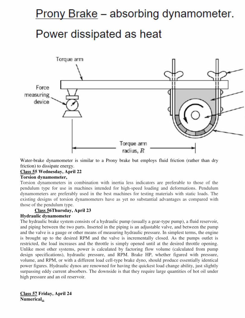
Water-brake dynamometer is similar to a Prony brake but employs fluid friction (rather than dry
friction) to dissipate energy.
Class 55 Wednesday, April 22
Torsion dynamometer,
Torsion dynamometers in combination with inertia less indicators are preferable to those of the
pendulum type for use in machines intended for high-speed loading and deformations. Pendulum
dynamometers are preferably used in the best machines for testing materials with static loads. The
existing designs of torsion dynamometers have as yet no substantial advantages as compared with
those of the pendulum type.
Class 56Thursday, April 23
Hydraulic dynamometer
The hydraulic brake system consists of a hydraulic pump (usually a gear-type pump), a fluid reservoir,
and piping between the two parts. Inserted in the piping is an adjustable valve, and between the pump
and the valve is a gauge or other means of measuring hydraulic pressure. In simplest terms, the engine
is brought up to the desired RPM and the valve is incrementally closed. As the pumps outlet is
restricted, the load increases and the throttle is simply opened until at the desired throttle opening.
Unlike most other systems, power is calculated by factoring flow volume (calculated from pump
design specifications), hydraulic pressure, and RPM. Brake HP, whether figured with pressure,
volume, and RPM, or with a different load cell-type brake dyno, should produce essentially identical
power figures. Hydraulic dynos are renowned for having the quickest load change ability, just slightly
surpassing eddy current absorbers. The downside is that they require large quantities of hot oil under
high pressure and an oil reservoir.
Class 57 Friday, April 24
Numerical..