Embed Size (px)
Citation preview

TI Designs
マルチ・スタンダードCC2650センサタグ・デザイン・ガイド
TI DesignsTI Designsは、システムをすばやく評価してカスタマイズす
るために必要な、手法、テスト、デザイン・ファイルなどの基盤を提供し、開発期間の短縮に役立ちます。
デザイン・リソースhttp://www.ti.com/tool/ デザイン・ファイTIDC-CC2650STK- SENSORTAG ルを含むツール・ フォルダhttp://www.ti.com/product/cc2650 製品フォルダhttp://www.ti.com/product/opt3001 製品フォルダhttp://www.ti.com/product/tmp007 製品フォルダhttp://www.ti.com/product/hdc1000 製品フォルダhttp://www.ti.com/tool/cc2650stk ツール・フォルダhttp://www.ti.com/tool/ccstudio ツール・フォルダ
● マルチ・スタンダードのワイヤレスMCUをサポート— Bluetooth® Smart— ZigBee®
— 6LoWPAN(IPv6 over Low-power Wireless Personal Area Networks)
● 低消費電力● 10個の低電力センサをサポート
— 周囲光— 赤外線温度— 周囲温度— 加速度計— ジャイロスコープ— 磁力計— 圧力— 湿度— マイクロフォン— 磁気センサ
● 超低電力/高性能のARM® Cortex®-M3 CC2650ワイヤレスMCUをベース
● DevPackを使用し、設計のアイデアに合わせてセンサタグの機能を拡張可能— Code Composer Studio™ IDEの無料ライセン
スを含むエミュレータ・デバッグDevPackによって包括的な開発システムを構築
主なアプリケーション● スマートフォン用ハンドセット● ホーム・オートメーション● センサ・ノード● スマート・ウォッチ● ウェザー・ステーション
この資料は、Texas Instruments Incorporated(TI)が英文で記述した資料を、皆様のご理解の一助として頂くために日本テキサス・インスツルメンツ
(日本TI)が英文から和文へ翻訳して作成したものです。資料によっては正規英語版資料の更新に対応していないものがあります。日本TIによる和文資料は、あくまでもTI正規英語版をご理解頂くための補助的参考資料としてご使用下さい。製品のご検討およびご採用にあたりましては必ず正規英語版の最新資料をご確認下さい。TIおよび日本TIは、正規英語版にて更新の情報を提供しているにもかかわらず、更新以前の情報に基づいて発生した問題や障害等につきましては如何なる責任も負いません。
TIDU862 翻訳版
最新の英語版資料http://www.ti.com/lit/tidu862
ASK Our E2E ExpertsWEBENCH® Calculator Tools
参考資料JAJU198
すべて商標および登録商標は、それぞれの所有者に帰属します。
デザインの特長● クラウド接続をすぐに使用可能
— どこからでもセンサタグにアクセスして制御でき、JavascriptおよびMQTTを通じてモバイル・アプリケーションやWebページとのシームレスな統合を実現

2 Multi-Standard CC2650 SensorTag Design Guide TIDU862–March 2015Submit Documentation Feedback
Copyright © 2015, Texas Instruments Incorporated
www.ti.com
Coin Cell/ 2x AAA
Buzzer
2x Push Buttons
LED
Reed Relay MK24
CC3200(WiFi)
CC2650(BLE/ZigBee)
9-axis Motion MPU-9250
Altimeter BMP280
Light Sensor OPT3001
Humidity/Temp HDC1000
IR Temp Sensor
TMP007
Microphone SPK0833
JTAG Interface
DevPack Interface
I2C
PDM
An IMPORTANT NOTICE at the end of this TI reference design addresses authorized use, intellectual property matters and otherimportant disclaimers and information.

3 Multi-Standard CC2650 SensorTag Design GuideTIDU862–March 2015Submit Documentation Feedback
Copyright © 2015, Texas Instruments Incorporated
System Descriptionwww.ti.com
Coin Cell/ 2x AAA
Buzzer
2x Push Buttons
LED
Reed Relay MK24
CC3200(WiFi)
CC2650(BLE/ZigBee)
9-axis Motion MPU-9250
Altimeter BMP280
Light Sensor OPT3001
Humidity/Temp HDC1000
IR Temp Sensor
TMP007
Microphone SPK0833
JTAG Interface
DevPack Interface
I2C
PDM
図 1. ブロック図
1 システム説明
1.1 マルチ・スタンダードCC2650センサタグ
このセンサタグ・キットを利用することで、ユーザーはさまざまなクラウド接続製品のアイデアを実現できます。新しいセンサタグは、小型のパッケージに10個の低電力MEMSセンサを搭載しています。また、DevPackによって拡張可能であるため、ユーザー独自のセンサやアクチュエータを簡単に追加できます。
Bluetooth Smartを使用してクラウドに接続し、センサ・データをわずか3分でオンラインで取得できます。センサタグは購入後すぐにiOS™やAndroid™のアプリケーションで利用でき、プログラミング経験は必要ありません。
センサタグは、低電力で高性能のCC2650ワイヤレスMCUをベースとし、以前のBluetooth Smart製品と比べて消費電力を75%削減しています。このように低い消費電力により、センサタグはバッテリ電力で駆動でき、1個のコイン電池で数年間稼働できます。
このBluetooth Smartセンサタグには、iBeacon™テクノロジーが使用されています。このテクノロジーにより、センサタグのデータと現在の物理的な位置に基づいて、スマートフォンでアプリケーションを起動したりコンテンツをカスタマイズしたりできます。
センサタグは、ZigBee/6LoWPANテクノロジーにも対応しています。センサタグで使用されるテクノロジーの詳細については、www.ti.com/SensorTagをご覧ください。
1.1.1 ブロック図

4 Multi-Standard CC2650 SensorTag Design Guide TIDU862–March 2015Submit Documentation Feedback
Copyright © 2015, Texas Instruments Incorporated
Highlighted Products www.ti.com
2 使用製品このデザインには、以下のデバイスが使用されています。
• CC2650 • OPT3001 • TMP007 • HDC1000
これらのデバイスの詳細については、www.TI.comで各製品フォルダをご覧ください。
2.1 CC2650 - ワイヤレスMCU
CC2650デバイスは、Bluetooth Smart、ZigBee、6LoWPAN、およびZigBee RF4CEリモート制御アプリケーションを対象としたワイヤレスMCUです。
このデバイスは、コスト・パフォーマンスが高く消費電力が非常に低い、CC26xxファミリの2.4GHz RFデバイスの1つです。アクティブなRFおよびMCU電流、および低電力モード電流の消費が非常に小さいため、デバイスのバッテリ寿命が長くなります。また、それにより、デバイスが小型のコイン電池で動作でき、エネルギー・ハーベスティング・アプリケーションにも利用できます。
図 2. CC2650の機能ブロック図

5 Multi-Standard CC2650 SensorTag Design GuideTIDU862–March 2015Submit Documentation Feedback
Copyright © 2015, Texas Instruments Incorporated
Highlighted Productswww.ti.com
2.2 OPT30001 - 周囲光センサ
OPT3001センサは、可視光の輝度を測定します。センサのスペクトル応答は、人間の目の明所視応答と厳密に一致し、赤外線除去にも対応しています。
SCLSDA
ADDR
VDD
OPT3001
INTAmbientLight
GND
I2CInterface
VDD
ADCOpticalFilter
図 3. OPT3001の機能ブロック図

6 Multi-Standard CC2650 SensorTag Design Guide TIDU862–March 2015Submit Documentation Feedback
Copyright © 2015, Texas Instruments Incorporated
Highlighted Products www.ti.com
2.3 TMP007 - 赤外線サーモパイル温度センサ
TMP007センサは、対象物に直接接触せずにその温度を測定できる、IRサーモパイル・センサです。内蔵のサーモパイルによって、センサの視界内にある対象物からの赤外線エネルギーを吸収します。デバイスではサーモパイル電圧をデジタル化した後、その値とダイ温度を内蔵の数値計算エンジンに入力します。数値計算エンジンによって、対応する対象物の温度が計算されます。
2.4 HDC1000 - 温度センサを内蔵した湿度センサ
HDC1000センサは、工場出荷時に校正されるデジタル湿度センサであり、内蔵温度センサによって、非常に低い電力で正確な測定結果が得られます。HDC1000センサは、新開発の容量性センサに基づいて湿度を測定し、-40°C~125°Cの温度範囲内で機能します。革新的なWLCSP(ウェハー・レベル・チップ・スケール・パッケージ)による超小型のパッケージで基板設計が簡素化され、HDC1000デバイスの底面にあるセンシング素子は汚れやほこりなどの汚染物質から保護されています。
16-BitADC
Gain
LocalTemperature
IRThermopile
SensorVoltage
Reference
DigitalControl
andMath Engine
I C and2
SMBusCompatible
DigitalInterface
ALERTADR0ADR1SCLSDA
V+
TMP007
AGND DGND
EEPROM
GND
MCUI2C
Peripheral
3.3 V
ADC
TEMPERATURE
RH
I2CRegisters
+ Logic
HDC1000SDASCL
DRDYnADR0
OTPCalibration Coefficients
ADR1
VDD
GND
3.3 V
VDD
GPIO
3.3 V
図 4. TMP007の機能ブロック図
図 5. HDC1000の機能ブロック図

7 Multi-Standard CC2650 SensorTag Design GuideTIDU862–March 2015Submit Documentation Feedback
Copyright © 2015, Texas Instruments Incorporated
System Design Theorywww.ti.com
3 システム設計理論センサタグは包括的な開発キットとして提供され、キットのテストを開始するのに組み込みソフトウェアの知識は必要ありま
せん。Bluetooth Smartを使用してセンサタグをスマートフォンに接続したら、スマートフォンを使用してクラウドに接続し、わずか数分で最新の測定データにオンラインでアクセスできます。iBeaconを使用することにより、センサタグのデータと現在の物理的な位置に基づいて、スマートフォンでアプリケーションを起動したりコンテンツをカスタマイズしたりできます。
既存のアプリケーションやサポートされるiOSおよびAndroidのアプリケーションをすぐに使用でき、またはセンサタグを使用して低電力センサによる独自の製品を開発することもできます。
3.1 アプリケーションとWeb開発
クラウド・プロバイダを通してセンサタグのデータにアクセスするか、またはJavaScriptおよびjQueryのサンプルを使用して直接データにアクセスできます。AndroidやiOSのモバイル・アプリケーションを出発点として独自のIoT(Internet of Things)プロジェクトを推進したり、またはサンプルWebアプリケーション・プロジェクトのソース・コードに基づいてHTML5プラットフォームに依存しないコードを記述したりできます。
3.2 組み込みソフトウェア開発
センサタグは、低電力IoTノードに対するオープンなハードウェアおよびソフトウェア・リファレンス・デザインを低コストで提供します。センサタグとデバッグDevPackの組み合わせによって、ハードウェア開発用のプラットフォームを低コストで構築できます。異なる無線規格の間でセンサタグ・アプリケーションを移植しながら、アプリケーションに対してどのワイヤレス・テクノロジーが適切であるかをすばやく評価することもできます。
3.3 ハードウェア開発
センサタグのハードウェアをIoTプロジェクト用の開発プラットフォームとして使用できます。このオープンなハードウェアは、10個の低電力センサの使用方法のデモを示しています。DevPackインターフェイスによって、IoTクラウド上で独自のセンサやアクチュエータを容易に開発およびテストできます。

8 Multi-Standard CC2650 SensorTag Design Guide TIDU862–March 2015Submit Documentation Feedback
Copyright © 2015, Texas Instruments Incorporated
Getting Started www.ti.com
4 開発の開始4.1 ハードウェア
センサタグ・キットには、開発を開始するために必要なすべてのものが含まれています。Apple App Store™またはGoogle Play™から無料のセンサタグ・アプリケーションをダウンロードして、IoT開発を開始できます。
4.2 ファームウェア4.2.1 Bluetooth Low Energyスタック(BLE-STACK-2)には、センサタグのBluetooth Low Energyファームウェアのダウンロー
ド・リンクが含まれています。
4.2.2 センサタグZigBeeファームウェア
ZigBeeスタック(Z-STACK-HOME)には、センサタグのZigBeeファームウェアのダウンロード・リンクが含まれています。
4.2.3 センサタグ6LowPANファームウェア
Contikiスタックには、センサタグの6LowPANファームウェアのダウンロード・リンクが含まれています。
5 テストの設定長さ3mのRFシールド・ルーム(無響室)内で、アンテナ放射パターンを測定しました。被試験デバイス(DUT)を送信モードに設定
し、回転させることで、360°のアンテナ放射パターンを作成しました。測定アンテナは、部屋の反対側に配置しました。DUTから2440MHzの連続波(CW)を送信し、方位角および仰角を15°ずつ変化させながらアンテナで電波を測定しました。図6、図7、および図8に、テスト設定を示します。
www.ti.com Test Setup
Figure 6. Antenna Radiation Pattern
9TIDU862–March 2015 Multi-Standard CC2650 SensorTag Design GuideSubmit Documentation Feedback
Copyright © 2015, Texas Instruments Incorporated

Test Setup www.ti.com
Figure 7. DUT Mounted On Rotating Arm
10 Multi-Standard CC2650 SensorTag Design Guide TIDU862–March 2015Submit Documentation Feedback
Copyright © 2015, Texas Instruments Incorporated

www.ti.com Test Setup
Figure 8. Measurement Antenna
11TIDU862–March 2015 Multi-Standard CC2650 SensorTag Design GuideSubmit Documentation Feedback
Copyright © 2015, Texas Instruments Incorporated

Test Data www.ti.com
6 Test Data
Figure 9. Theta = 0, Phi = 0
12 Multi-Standard CC2650 SensorTag Design Guide TIDU862–March 2015Submit Documentation Feedback
Copyright © 2015, Texas Instruments Incorporated

www.ti.com Test Data
Figure 10. Theta = 180, Phi = 0
13TIDU862–March 2015 Multi-Standard CC2650 SensorTag Design GuideSubmit Documentation Feedback
Copyright © 2015, Texas Instruments Incorporated

Test Data www.ti.com
Figure 11. Theta = 90, Phi = 0
14 Multi-Standard CC2650 SensorTag Design Guide TIDU862–March 2015Submit Documentation Feedback
Copyright © 2015, Texas Instruments Incorporated

www.ti.com Test Data
Figure 12. Theta = 90, Phi = 180
15TIDU862–March 2015 Multi-Standard CC2650 SensorTag Design GuideSubmit Documentation Feedback
Copyright © 2015, Texas Instruments Incorporated

Test Data www.ti.com
Figure 13. Theta = 90, Phi = 270
16 Multi-Standard CC2650 SensorTag Design Guide TIDU862–March 2015Submit Documentation Feedback
Copyright © 2015, Texas Instruments Incorporated

www.ti.com Test Data
Figure 14. Theta = 90, Phi = 90
17TIDU862–March 2015 Multi-Standard CC2650 SensorTag Design GuideSubmit Documentation Feedback
Copyright © 2015, Texas Instruments Incorporated

VDD VDD
JTAG_TCKJTAG_TMS
BUTTON1BUTTON2LED1
VDD
SDASCL
SDA HPSCL HP
SCLSDA
SCL HPSDA HP
MPU INTREED
nRESET
MIC PWR
AUDIO DI
BUZZER
DP_ID
SCLSDA
DP6/AUDIO DODP7/AUDIO CLK
DP0DP1DP2DP3DP4/UART_RXDP5/UART_TX
DP8/SCLK/TDIDP9/MISODP10/MOSIDP11/CSNDP12/AUDIO FS/TDO
MPU INTREED
DP_ID
DP6/AUDIO DODP7/AUDIO CLK
DP0DP1DP2DP3DP4/UART_RXDP5/UART_TX
DP8/SCLK/TDIDP9/MISODP10/MOSIDP11/CSNDP12/AUDIO FS/TDO
MPU PWR
MPU PWR
FLASH_CS
FLASH_CS
LED2
TMP RDY
nRESET
AUDIO DIMIC PWR
BUZZERTMP RDY
DP7/AUDIO CLK
DP12/AUDIO FS/TDO
N1
Sensors
VDD
SCLSDA
MIC PWR
SDA HPSCL HP
MPU PWR
MPU INT
AUDIO DI
REED
DP7/AUDIO CLK
TMP RDY
DP12/AUDIO FS/TDO
H1
CC2650
VDD
SCLSDA
SDA HPSCL HP
MIC PWR
JTAG_TCKJTAG_TMS
nRESET
FLASH_CS
BUTTON1BUTTON2
LED1LED2
DP0
DP4/UART_RX
DP1DP2DP3
DP12/AUDIO FS/TDO
DP6/AUDIO DO
DP11/CSN
DP9/MISO
DP5/UART_TX
DP8/SCLK/TDI
DP10/MOSI
DP7/AUDIO CLK
AUDIO DI
REEDMPU INT
TMP RDYBUZZER
MPU PWR
DP_ID
K1
Peripheral and Power
BUTTON1
VDD
JTAG_TCKJTAG_TMS
BUTTON2
nRESET
SCLSDA
FLASH_CS
LED1LED2
DP4/UART_RX
DP0DP1DP2DP3
DP10/MOSI
DP6/AUDIO DO
DP12/AUDIO FS/TDODP11/CSN
DP9/MISO
DP5/UART_TX
DP8/SCLK/TDIDP7/AUDIO CLK
BUZZER
DP_ID
Design Files www.ti.com
7 Design Files
7.1 SchematicsTo download the schematics for each board, see the design files at SWRR134.
Figure 15. CC2650STK Schematics
18 Multi-Standard CC2650 SensorTag Design Guide TIDU862–March 2015Submit Documentation Feedback
Copyright © 2015, Texas Instruments Incorporated

VDDS Decoupling Capacitors
Pin 22Pin 13 Pin 34Pin 44 Pin 48Pin 45
VDDR Decoupling Capacitors
Coaxialswitch
DCDC_SW
DCDC_SWVDD
DP4/UART_RX
LED1SCL HP
MPU INT
SDA HP
DP9/MISODP10/MOSI
MIC PWR
DP11/CSN
DP_ID
DP2DP1DP0
DP3
DP8/SCLK/TDI
DP6/AUDIO DO
DP12/AUDIO FS/TDO
DP7/AUDIO CLK
SDA
JTAG_TMSJTAG_TCK
nRESET
VDD
BUTTON2
BUTTON1
LED2
BUZZER
DP5/UART_TXFLASH_CS
SCL
AUDIO DI
MPU PWR
REED
TMP RDY
VDD
VDDS
VDDS VDDR
VDDR
VDDS
MPU PWRVDD
U1A
CC26xx-7x7
JTAG_TMSC24
JTAG_TCKC25
RESET_N35
DCDC_SW33
X32K_Q13
X32K_Q24
DCOUPL23
VSS49
VDDS213
VDDS322
VDDS44
VDDS_DCDC34
VDDR45
VDDR48
RF_P1
RF_N2
X24M_N46
X24M_P47
C1
DNM
ANT2
DNM
FL1
BLM18HE152SN1
12
A1
2.4GHz
32
1
L3
2.4nH
1 2
C4100nF
L2
2.4nH
1
2
C710uF
Y1
32.768kHz
J1
MS-156HF
12
34
C9100nF
C13
1pF
L110uH
1 2
C17
DNM_0402
C8100nF
C11
1pF
C16
1uF
CC26xx-7x7
U1B
DIO_05
DIO_16
DIO_27
DIO_38
DIO_49
DIO_510
DIO_611
DIO_712
DIO_814
DIO_915
DIO_1016
DIO_1117
DIO_1218
DIO_1319
DIO_1420
DIO_1521
DIO_1626
DIO_1727
DIO_1828
DIO_1929
DIO_2030
DIO_2131
DIO_2232
DIO_2336
DIO_2437
DIO_2538
DIO_2639
DIO_2740
DIO_2841
DIO_2942
DIO_3043
ANT5
0
C3100nF
R6
200k
ANT6
0.5pF
C14
12pF
C18
DNM_0402
C5
22uF
C15
12pF
R310k
R210k
C31
DNM
R510k
ANT4
2nH
1 2
R410k
C2100nF
R1
100k
ANT1
2nH
1 2
Y2
24MHz
1
2 4
3
C33 15pF
C6100nF
ANT3
1pF
C12100nF
C32 15pF
www.ti.com Design Files
Figure 16. CC2650STK Schematics
19TIDU862–March 2015 Multi-Standard CC2650 SensorTag Design GuideSubmit Documentation Feedback
Copyright © 2015, Texas Instruments Incorporated

LEDs and Buttons
Buzzer
Debug / JTAG interface
SKIN Connector
Battery interface
External storage
POWER GOOD
VDD_BATT
DevPack->VDD
LED1
JTAG_TCKJTAG_TMS VDD
nRESET
BUZZER
VDD
DP12/AUDIO FS/TDO
DP_ID
DP11/CSN
DP9/MISODP10/MOSI
DP8/SCLK/TDI
SDASCLVDD
VDD
DP8/SCLK/TDIDP12/AUDIO FS/TDO
DP10/MOSI
FLASH_CS
DP9/MISO
VDD
VDD
BUTTON1
BUTTON2
LED2
DP5/UART_TX
DP7/AUDIO CLK
DP0
DP2DP1
DP3DP4/UART_RX
DP6/AUDIO DO
DP8/SCLK/TDI
R1710k
U10
W25X20CLUXIG
GND4
VCC8
nCS1 CLK6 DI/IO05
DO/IO12nWP
3
nHOLD7
EGP9
R10680
R27150
R21270
R162.2k
++-
BT1
BAT-HLD-001
123
U2
TS5A3159AYZPR
INA2
GNDB1
NOA1
COMC2
NCC1
V+B2
R22270
CR3
LPL296-J2L2-25
2 1
R260
R85.1
CR1
LS L296-P2Q2-1
2 1
R120
R7
10k
R9
2Meg
MTA2-WNC
SW212
J2
LSS-110-01-F-DV-A-TR
13579
1113151719
2468101214161820
Q1BC846B
1
3
2
R23DNM
MTA2-WNC
SW112
-
BAT-
C28
100nF
+
BAT+
P1
BB02-BS101-KA8-025B00
2468
10
13579
R1810k
+
-
BZ1HCS0503B
2
1
3
Design Files www.ti.com
Figure 17. CC2650STK Schematics
20 Multi-Standard CC2650 SensorTag Design Guide TIDU862–March 2015Submit Documentation Feedback
Copyright © 2015, Texas Instruments Incorporated

Reed Relay Pressure Sensor
Gyroscope and accelerometer
Infrared Thermopile Sensor
Humidity
Light Sensor
Digital Microphone
VDD
VDD
SCL HPSDA HP
MPU INT
VDD REED
SCLSDA
VDD
SCL
SDA
VDDSCL
SDA
SCL
SDA
VDD
MPU PWR
VDD
TMP RDY
VDD
MPU PWR
MIC PWR
AUDIO DI
DP7/AUDIO CLK
MPU PWR
VDD
SW3
MK24-A
21
R502.2k
R320
C20
100nF
R310
C2610nF
MPU-9250
U8
NC_66
AUX_DA21
AUX_CL7
VDDIO8
AD0/SDO9
REGOUT10
FSYNC11
INT12
VDD13
GND18
RESV_1919
RESV_11
RESV_2020
nCS22
SCL/SCLK23 SDA/SDI24
EGP25
NC_1414
NC_1515
NC_1616
NC_1717
NC_22
NC_33
NC_44
NC_55
C22
100nF
U9
HDC1000YPA
GNDB2
SDAA2
SCLA1
VDDB1
ADR0C1
ADR1D1
nDRDYD2
DNCC2
TMP007
U4
nALERTC2SDA
C3
DGNDA1
AGNDA2
V+A3
ADR1B1
SCLB3
ADR0C1
C21
100nF
OPT3001
U7
nINT5
ADDR2
VDD1
GND3
EGP/GND7
nCLK4
DATA6
U3
BMP280
GND1
CSB2
VDDIO6
GND7
SDI3
SCK4
SDO5 VDD
8
C23
100nF
C25100nF
U6
SPH0641LU4H
VDD5
SELECT2
CLOCK4
DATA1
GND3
C19
100nF
C27100nF
R110
C24
100nF
www.ti.com Design Files
Figure 18. CC2650STK Schematics
21TIDU862–March 2015 Multi-Standard CC2650 SensorTag Design GuideSubmit Documentation Feedback
Copyright © 2015, Texas Instruments Incorporated

Design Files www.ti.com
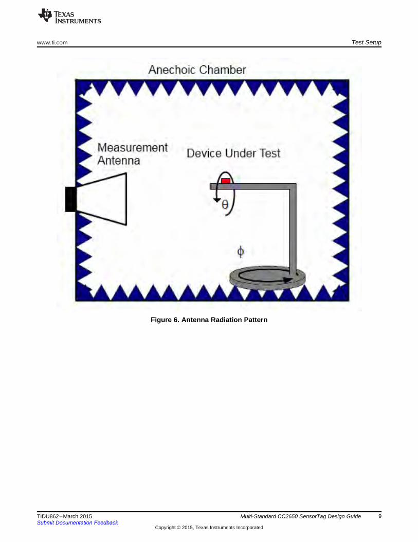
7.2 Bill of MaterialsTo download the bill of materials (BOM), see the design files at SWRR135.
Table 1. BOM
ITEM PART QUANTITY VALUE DESCRIPTION MPN MANUFACTURERNUMBER REFERENCE1 A1 1 DNM Mechanic, 2.4-GHz inverted F antenna, SMD DN007 TI2 ANT1, ANT4 2 2 nH Inductor, Chip, 2 nH, –0.3 nH / +0.3 nH, 0.3 A, LQG15HS2N0S02D Murata
–55°C / 125°C,0402, SMD
3 ANT2, C17, C18, C31 4 DNM Capacitor, Ceramic, N/A value, –55°C / 125°C, CAPACITOR_0402_DNM_N/A_M Manufacturer0402, SMD Selection
4 ANT3, C11, C13 3 1 pF Capacitor, Ceramic C0G / NP0, 1 pF, GRM1555C1H1R0CA01D Murata50 V, –0.25 pF / 0.25 pF,–55°C / 125 °C, 0402, SMD
5 ANT5, R12, R26 3 0 Resistor, Thick Film, 0, – 5% / 5%, 0.063 W, RESISTOR_0402_0_ Manufacturer50 V, –55°C / 155°C, 0402, SMD ±5%_50V_0.063W_M_±200PPM Selection
6 ANT6 1 0.5 pF Capacitor, Ceramic C0G / NP0, 0.5 pF, 50 V, GRM1555C1HR50BA01D Murata–0.1 pF / 0.1 pF,–55°C / 125°C, 0402, SMD
7 BAT+ 1 DNM Noncomponent, Battery + Pad, SMD8 BAT– 1 DNM Noncomponent, Battery – Pad, SMD9 BT1 1 BAT-HLD-001 Battery, BAT-HLD-001 Linx
Holder for CR2032 and CR2025 batteries, SMD10 BZ1 1 HCS0503B Acoustic, Buzzer, 3 V, –40°C / 85°C, SMD HCS0503B Changzhou
Tianyin11 C1 1 DNM Capacitor, Ceramic X5R, 2.2 µF, 10 V, GRM188R61A225ME34D Murata
–20% / 20%, –55°C / 85°C, 0603, SMD12 C2, C3, C4, C6, C8, C9, 7 100 nF Capacitor, Ceramic X7R, 100 nF, 6.3 V, GRM155R70J104KA01D Murata
C12 –10% / 10%, –55°C / 125°C, 0402, SMD13 C5 1 22 µF Capacitor, Ceramic X5R, 22 µF, 4 V, GRM188R60G226MEA0D Murata
–20% / 20%, –55°C / 85°C, 0603, SMD14 C7 1 10 µF Capacitor, Ceramic X5R, 10 µF, 6.3 V, GRM188R60J106ME47D Murata
–20% / 20%, –55°C / 85°C, 0603, SMD15 C14, C15 2 12 pF Capacitor, Ceramic C0G / NP0, 12 pF, GRM1555C1H120JA01D Murata
50 V, –5% / +5%, –55 DEGC / +125 DEGC,0402, SMD
16 C16 1 1 µF Capacitor, Ceramic X5R, 1 µF, 10 V, GRM155R61A105KE15D Murata–10% / 10%, –55°C / 85°C, 0402, SMD
17 C19, C20, C21, C22, C23, 9 100 nF Capacitor, Ceramic X5R, 100 nF, 10 V, CAPACITOR_0201_100nF_ ManufacturerC24, C25, C27, C28 –10% / 10%, –55°C / 85°C, 0201, SMD X5R_I_±10%_10V Selection
22 Multi-Standard CC2650 SensorTag Design Guide TIDU862–March 2015Submit Documentation Feedback
Copyright © 2015, Texas Instruments Incorporated

www.ti.com Design Files
Table 1. BOM (continued)ITEM PART QUANTITY VALUE DESCRIPTION MPN MANUFACTURERNUMBER REFERENCE
18 C26 1 10 nF Capacitor, Ceramic X5R, 10 nF, 10 V, GRM033R71A103KA01D Murata–10% / 10%, –55°C / 125°C, 0201, SMD
19 C29 1 DNM20 C32, C33 2 15 pF Capacitor, Ceramic, 15 pF, 50 V, GRM0332C1H150JA01D Murata
–5% / 5%, –55°C / 125°C, 0201, SMD21 CR1 1 LS L296-P2Q2-1 Opto, LED, Super Red Color, 630 nm, LS L296-P2Q2-1-Z Osram
1.8 V TO 2.3 V, 0.06 A, 0603, SMD22 CR3 1 LPL296-J2L2-25 Opto, LED, Green Color, 562 nm, LP L296-J2L2-25 Osram
0.02 A, 0.08 W, 0603, SMD23 FIDU1, FIDU2, FIDU3, 6 DNM Fiducial Mark, Round 1.27 mm
FIDU4, FIDU5, FIDU624 FL1 1 BLM18HE152SN1 Filter, EMI, 1500 @ 100 MHz, BLM18HE152SN1D Murata
–55°C / 125°C, 0603, SMD25 J1 1 MS-156HF Connector Coax RF, Straight, Female, SMD MS-156HF Hirose26 J2 1 LSS-110-01-F-DV-A- Connector, Header, Hi-speed Socket, Female, LSS-110-01-F-DV-A-TR Samtec
TR Straight, 2 Rows,20 Pins, Pitch 0.635 mm, SMD
27 L1 1 10 µH Inductor, Chip, 10 µH, –20% / 20%, CKS2125100M-T Taiyo Yuden0.11 A, –40°C / 85°C, 0805, SMD
28 L2, L3 2 2.4 nH Inductor, Chip, 2.4 nH, –0.3 nH / 0.3 nH, LQG15HS2N4S02D Murata0.3 A, –55°C / 125°C, 0402, SMD
29 P1 1 BB02-BS101-KA8- Connector, Header, Male, 2 Rows, BB02-BS101-KA8-025B00 Gradconn025B00 10 Pins, Pitch 1.27 mm, SMD
30 Q1 1 BC846B Transistor, Bipolar NPN, BC846B,215 NXP65 V, 0.1 A, 0.25 W, SOT –23, SMD
31 R1 1 100 k Resistor, Thick Film, 100 k, –5% / 5%, RESISTOR_0402_100k_ Manufacturer0.063 W, 50 V, -55°C / 155°C, 0402, SMD +/-5%_50V_0.063W_M_±200PPM Selection
32 R2, R3, R4, R5, R7, R17, 7 10 k Resistor, Thick Film, 10 K, –5% / 5%, RESISTOR_0201_10k_ ManufacturerR18 0.05 W, 30 V, –55°C / 125°C, 0201, SMD ±5%_30V_0.05W_M_±200ppm Selection
33 R6 1 200 k Resistor, Thick Film, 200 K, –1% / 1%, CRCW0201200KFKED Vishay Dale0.05 W, 30 V, –55°C / 125°C, 0201, SMD
34 R8 1 5.1 Resistor, Thick Film, 5R1, –5% / 5%, RMC1/205R1JPA Kamaya0.05 W, 25 V, –55°C / 125°C, 0201, SMD
35 R9 1 2 MΩ Resistor, Thick Film, 2M, –1% / 1%, RC0402FR-072ML Yageo0.063 W, 50 V, –55°C / 155°C, 0402, SMD
36 R10 1 680 Resistor, Thick Film, 680, –5% / 5%, RESISTOR_0402_680_±5%_50V_ Manufacturer0.063 W, 50 V, –55°C / 155°C, 0402, SMD 0.063W_M_±200PPM Selection
37 R11, R31, R32 3 0 Resistor, Thick Film, 0, –1% / 1%, RESISTOR_0201_0_±1%_30V_ Manufacturer0.05 W, 30 V, –55°C / 155°C, 0201, SMD 0.05W_M_±100PPM Selection
23TIDU862–March 2015 Multi-Standard CC2650 SensorTag Design GuideSubmit Documentation Feedback
Copyright © 2015, Texas Instruments Incorporated
Design Files www.ti.com
Table 1. BOM (continued)ITEM PART QUANTITY VALUE DESCRIPTION MPN MANUFACTURERNUMBER REFERENCE
38 R16, R50 2 2.2 k Resistor, Thick Film, 2K2, –5% / 5%, CRCW02012K20JNED Vishay0.05 W, 30 V, –55°C / 125°C, 0201, SMD
39 R21, R22 2 270 Resistor, Thin Film, 270, –5% / +5%, RESISTOR_0402_270_±1%_50V_ Manufacturer0.0625 W, 50 V, –55 DEGC / +125 DEGCC, 0.063W_M_ ±200PPM Selection0402, SMD
40 R23 1 DNM Resistor, Do Not Mount, 0402, SMD DNM Do Not Mount41 R27 1 150 Resistor, Thick Film, 150, –5% / +5%, RESISTOR_0402_150_±5%_50V_ Manufacturer
0.063 W, 50 V, –55 DEGC / +155 DEGC, 0402, 0.063W_M_±200PPM SelectionSMD
42 SW1, SW2 2 MTA2-WNC Switch, Tact Switch, Right Angle, 0.05 A @ 12 MTA2-WNC-V-T/R DiptronicsVDC, SMD
43 SW3 1 MK24-A Switch, Other, Reed Sensor, MK24-A-3 MederSPST-NO, Pull-in: 23 AT to 50 AT,0.3 A @ 60 V, 0.3 A, 60 V, SMD
44 U1 1 CC26xx-7x7 IC, Digital, TI Custom 26xx, QFN48, SMD CC26xx_7x7_QFN48 TI45 U2 1 TS5A3159AYZPR IC, Analog, SPDT Switch Single-channel 2:1 TS5A3159AYZPR TI
Multiplexer / Demultiplexer,4.5 V to 5.5 V, DSBGA6, SMD
46 U3 1 BMP280 IC, Transducer Pressure, 300 hPa to 110 hPa, BMP280 Bosch1.71 V to 3.6 V, LGA8, SMD
47 U4 1 TMP007 IC, Transducer, TMP007AIYZFR TIInfrared Thermopile Sensor,2.5 V to 5.5 V, DSBGA8, SMD
48 U6 1 SPH0641LU4H IC, Digital, Microphone with Multiple SPH0641LU4H KnowlesPerformance Mode,1.62 V to 3.6 V, SMD
49 U7 1 OPT3001 IC, Analog, OPT3001, SON6, SMD OPT3001 TI50 U8 1 MPU-9250 IC, Transducer, 3-AXIS Accelerometer, 3-AXIS MPU-9250 Invensense
Gyroscope, 2.4 V to 3.6 V, QFN24, SMD51 U9 1 HDC1000YPA IC, Transducer, Low-power, High-accuracy HDC1000YPAR TI
Digital Humidity Sensor with IntegratedTemperature Sensor,2.7 V TO 5.5 V, DSBGA8, SMD
52 U10 1 W25X40CLUXIG IC, Memory, 4 M-bit of Serial Flash Memory, W25X40CLUXIG Winbond2.3 V to 3.6 V, USON8, SMD
53 U11 1 DNM54 Y1 1 32.768 kHz Crystal, Resonator, 32.768 kHz, FC-135 32.7680KA-AG0 Epson
–20 PPM / 20 PPM, –40°C / 85°C, SMD
24 Multi-Standard CC2650 SensorTag Design Guide TIDU862–March 2015Submit Documentation Feedback
Copyright © 2015, Texas Instruments Incorporated

www.ti.com Design Files
Table 1. BOM (continued)ITEM PART QUANTITY VALUE DESCRIPTION MPN MANUFACTURERNUMBER REFERENCE
55 Y2 1 24 MHz Crystal, Crystal Oscillator, TSX-3225 24.0000MF15X-AC3 Epson24 MHz, –15 PPM / °C / 15 PPM / °C,–40°C / 85°C, SMD
25TIDU862–March 2015 Multi-Standard CC2650 SensorTag Design GuideSubmit Documentation Feedback
Copyright © 2015, Texas Instruments Incorporated

26 Multi-Standard CC2650 SensorTag Design Guide TIDU862–March 2015Submit Documentation Feedback
Copyright © 2015, Texas Instruments Incorporated
Design Files www.ti.com
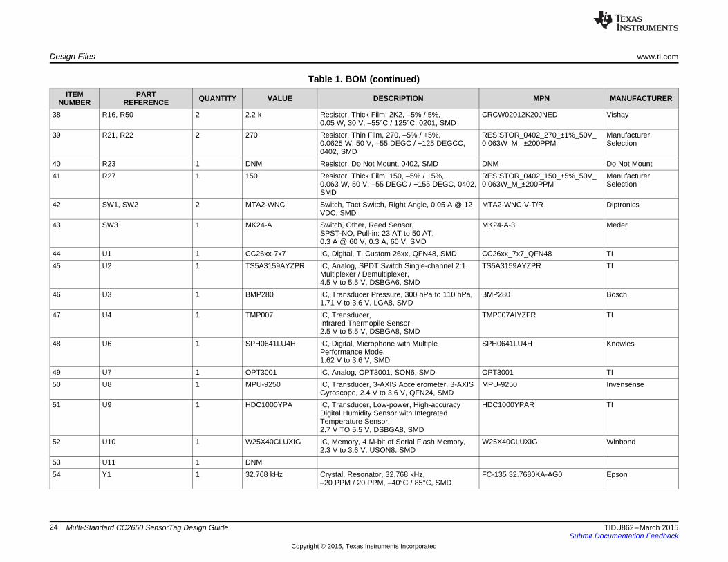
7.3 PCBレイアウトに関する推奨事項
7.3.1 CC2650ワイヤレスMCUのレイアウトに関する考慮事項
レイアウトについては以下の事項を考慮する必要があります。 • RF部品のレイアウトはリファレンス・デザインに従う必要があります。 • グランドに接続されるRF部品に対しては、グランド・インピーダンスを最小限に抑えるために、グランド・パッドの近くに複数
のグランド・ビアを配置する必要があります。 • すべてのRF部品の下(アンテナから、露出したグランド・パッド内のグランド・ビアまでの間)に、切れ目のないソリッドなグ
ランド・プレーンを配置する必要があります。 • RFパスの下にパターンが配置されないように、CC2650デバイスにできる限り近づけてバランまたはRFフィルタを配置します。 • アンテナ・マッチング用の部品は、できる限りアンテナに近づけて配置します。 • デカップリング・コンデンサは、対応するVDDピンにできる限り近づけて配置します。 • デカップリング・コンデンサからEGPまでのグランド・リターン・パスは、できる限り短く直接的に配線します。 • DCDC部品(L1およびC7)はDCDC_SWピンに近づけて配置します。 • DCDCコンデンサのグランド接続は、グランド・スイッチング・ノイズを避けるために、できる限り短く直接的に配線します。 • 湿度センサおよびIR温度センサは、温度の影響を受けるため、バッテリ、ディスプレイ、マイコンなど基板上の高熱源から離し
て配置します。 • 環境の変化に対して迅速に応答できるように、デバイスの周囲にスロットを使用して熱質量を低減します。
図 19. RFレイアウトに関する考慮事項
www.ti.com Design Files
Figure 20. DCDC Layout Considerations
27TIDU862–March 2015 Multi-Standard CC2650 SensorTag Design GuideSubmit Documentation Feedback
Copyright © 2015, Texas Instruments Incorporated

Design Files www.ti.com
7.3.2 Layout Considerations for Humidity Sensor – HDC1000
Figure 21. HDC1000
28 Multi-Standard CC2650 SensorTag Design Guide TIDU862–March 2015Submit Documentation Feedback
Copyright © 2015, Texas Instruments Incorporated

www.ti.com Design Files
Figure 22. HDC1000
7.3.3 Layout Considerations for the IR Temperature Sensor – TMP007For layout assembly considerations for the TMP007, see SBOU143.
7.3.4 Layout PrintsTo download the layout prints for each board, see the design files at SWRC304
29TIDU862–March 2015 Multi-Standard CC2650 SensorTag Design GuideSubmit Documentation Feedback
Copyright © 2015, Texas Instruments Incorporated

Design Files www.ti.com
Figure 23. Top Silkscreen
Figure 24. Top Solder Mask
30 Multi-Standard CC2650 SensorTag Design Guide TIDU862–March 2015Submit Documentation Feedback
Copyright © 2015, Texas Instruments Incorporated

www.ti.com Design Files
Figure 25. Top Layer
Figure 26. Layer 2
31TIDU862–March 2015 Multi-Standard CC2650 SensorTag Design GuideSubmit Documentation Feedback
Copyright © 2015, Texas Instruments Incorporated

Design Files www.ti.com
Figure 27. Layer 3
Figure 28. Bottom Layer
32 Multi-Standard CC2650 SensorTag Design Guide TIDU862–March 2015Submit Documentation Feedback
Copyright © 2015, Texas Instruments Incorporated
www.ti.com Design Files
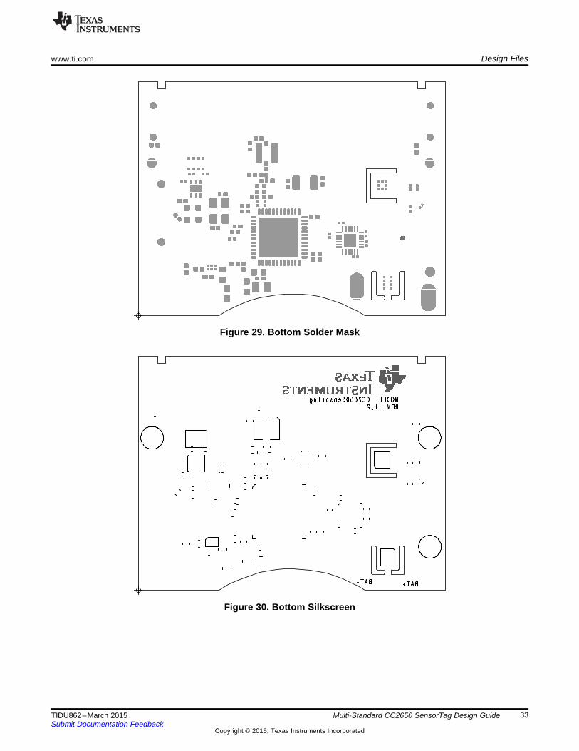
Figure 29. Bottom Solder Mask
Figure 30. Bottom Silkscreen
33TIDU862–March 2015 Multi-Standard CC2650 SensorTag Design GuideSubmit Documentation Feedback
Copyright © 2015, Texas Instruments Incorporated
Design Files www.ti.com
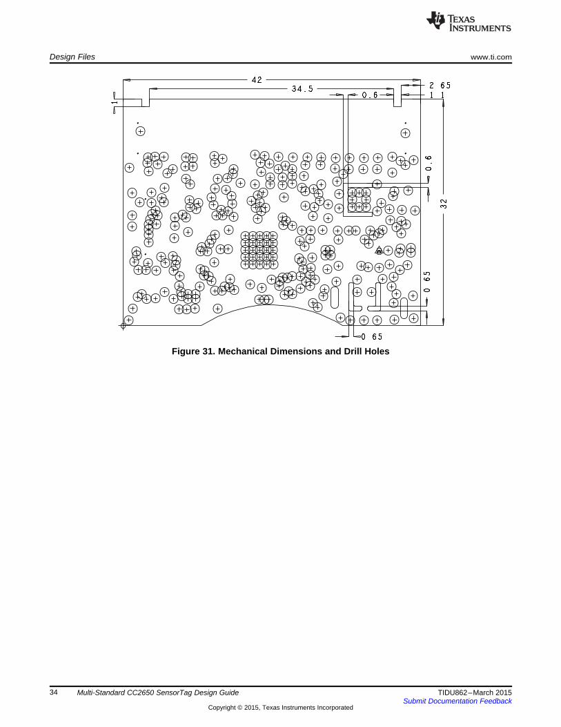
Figure 31. Mechanical Dimensions and Drill Holes
34 Multi-Standard CC2650 SensorTag Design Guide TIDU862–March 2015Submit Documentation Feedback
Copyright © 2015, Texas Instruments Incorporated

www.ti.com Design Files
7.4 Cadence Allegro ProjectDownload the Allegro project files for the SensorTag at SWRC304.
Figure 32. SensorTag Allegro project
35TIDU862–March 2015 Multi-Standard CC2650 SensorTag Design GuideSubmit Documentation Feedback
Copyright © 2015, Texas Instruments Incorporated

Design Files www.ti.com
7.5 Layout Guidelines
Figure 33. CC2650 SensorTag Layout Guidelines
36 Multi-Standard CC2650 SensorTag Design Guide TIDU862–March 2015Submit Documentation Feedback
Copyright © 2015, Texas Instruments Incorporated

www.ti.com Design Files
7.6 Gerber FilesTo download the Gerber files, see the design files at SWRC304.
Figure 34. CC2650STK Mechanical Drawing
7.7 Assembly DrawingsTo download the assembly drawings for each board, see the design files at SWRC304.
Figure 35. Assembly Drawing (Top) Figure 36. Assembly Drawing 2 (Bottom Side Mirrored)
7.8 Software FilesFor information regarding software, see Section 4.2.
37TIDU862–March 2015 Multi-Standard CC2650 SensorTag Design GuideSubmit Documentation Feedback
Copyright © 2015, Texas Instruments Incorporated

References www.ti.com
8 References
1. TI Technical Reference Manual, CC26xx SimpleLink™ Wireless MCU, SWCU1172. TI Application Note, SimpleLink™ Bluetooth Low Energy CC2640 Software Developer’s Guide,
SWRU3933. TI Application Note, OPT3001: Ambient Light Sensor Application Guide, SBEA0024. TI Application Note, TMP007 Layout and Assembly User Guide, SBOU1435. TI Application Note, Humidity Sensor, SNAA216
38 Multi-Standard CC2650 SensorTag Design Guide TIDU862–March 2015Submit Documentation Feedback
Copyright © 2015, Texas Instruments Incorporated

www.ti.com About the Author
9 About the AuthorESPEN SLETTE is a systems application engineer at TI, where he develops reference design solutionsfor wireless connectivity (that is, Wi-Fi, Bluetooth Smart, RF4CE, ZigBee / 6LoWPAN, and sub-1GHz).Espen Slette has experience in application support for wireless products and RF design. Espen Sletteearned his Master of Science in Electrical Engineering (MSEE) from NTNU in Trondheim, Norway.
39TIDU862–March 2015 Multi-Standard CC2650 SensorTag Design GuideSubmit Documentation Feedback
Copyright © 2015, Texas Instruments Incorporated

IMPORTANT NOTICE FOR TI REFERENCE DESIGNS
Texas Instruments Incorporated ("TI") reference designs are solely intended to assist designers (“Buyers”) who are developing systems thatincorporate TI semiconductor products (also referred to herein as “components”). Buyer understands and agrees that Buyer remainsresponsible for using its independent analysis, evaluation and judgment in designing Buyer’s systems and products.TI reference designs have been created using standard laboratory conditions and engineering practices. TI has not conducted anytesting other than that specifically described in the published documentation for a particular reference design. TI may makecorrections, enhancements, improvements and other changes to its reference designs.Buyers are authorized to use TI reference designs with the TI component(s) identified in each particular reference design and to modify thereference design in the development of their end products. HOWEVER, NO OTHER LICENSE, EXPRESS OR IMPLIED, BY ESTOPPELOR OTHERWISE TO ANY OTHER TI INTELLECTUAL PROPERTY RIGHT, AND NO LICENSE TO ANY THIRD PARTY TECHNOLOGYOR INTELLECTUAL PROPERTY RIGHT, IS GRANTED HEREIN, including but not limited to any patent right, copyright, mask work right,or other intellectual property right relating to any combination, machine, or process in which TI components or services are used.Information published by TI regarding third-party products or services does not constitute a license to use such products or services, or awarranty or endorsement thereof. Use of such information may require a license from a third party under the patents or other intellectualproperty of the third party, or a license from TI under the patents or other intellectual property of TI.TI REFERENCE DESIGNS ARE PROVIDED "AS IS". TI MAKES NO WARRANTIES OR REPRESENTATIONS WITH REGARD TO THEREFERENCE DESIGNS OR USE OF THE REFERENCE DESIGNS, EXPRESS, IMPLIED OR STATUTORY, INCLUDING ACCURACY ORCOMPLETENESS. TI DISCLAIMS ANY WARRANTY OF TITLE AND ANY IMPLIED WARRANTIES OF MERCHANTABILITY, FITNESSFOR A PARTICULAR PURPOSE, QUIET ENJOYMENT, QUIET POSSESSION, AND NON-INFRINGEMENT OF ANY THIRD PARTYINTELLECTUAL PROPERTY RIGHTS WITH REGARD TO TI REFERENCE DESIGNS OR USE THEREOF. TI SHALL NOT BE LIABLEFOR AND SHALL NOT DEFEND OR INDEMNIFY BUYERS AGAINST ANY THIRD PARTY INFRINGEMENT CLAIM THAT RELATES TOOR IS BASED ON A COMBINATION OF COMPONENTS PROVIDED IN A TI REFERENCE DESIGN. IN NO EVENT SHALL TI BELIABLE FOR ANY ACTUAL, SPECIAL, INCIDENTAL, CONSEQUENTIAL OR INDIRECT DAMAGES, HOWEVER CAUSED, ON ANYTHEORY OF LIABILITY AND WHETHER OR NOT TI HAS BEEN ADVISED OF THE POSSIBILITY OF SUCH DAMAGES, ARISING INANY WAY OUT OF TI REFERENCE DESIGNS OR BUYER’S USE OF TI REFERENCE DESIGNS.TI reserves the right to make corrections, enhancements, improvements and other changes to its semiconductor products and services perJESD46, latest issue, and to discontinue any product or service per JESD48, latest issue. Buyers should obtain the latest relevantinformation before placing orders and should verify that such information is current and complete. All semiconductor products are soldsubject to TI’s terms and conditions of sale supplied at the time of order acknowledgment.TI warrants performance of its components to the specifications applicable at the time of sale, in accordance with the warranty in TI’s termsand conditions of sale of semiconductor products. Testing and other quality control techniques for TI components are used to the extent TIdeems necessary to support this warranty. Except where mandated by applicable law, testing of all parameters of each component is notnecessarily performed.TI assumes no liability for applications assistance or the design of Buyers’ products. Buyers are responsible for their products andapplications using TI components. To minimize the risks associated with Buyers’ products and applications, Buyers should provideadequate design and operating safeguards.Reproduction of significant portions of TI information in TI data books, data sheets or reference designs is permissible only if reproduction iswithout alteration and is accompanied by all associated warranties, conditions, limitations, and notices. TI is not responsible or liable forsuch altered documentation. Information of third parties may be subject to additional restrictions.Buyer acknowledges and agrees that it is solely responsible for compliance with all legal, regulatory and safety-related requirementsconcerning its products, and any use of TI components in its applications, notwithstanding any applications-related information or supportthat may be provided by TI. Buyer represents and agrees that it has all the necessary expertise to create and implement safeguards thatanticipate dangerous failures, monitor failures and their consequences, lessen the likelihood of dangerous failures and take appropriateremedial actions. Buyer will fully indemnify TI and its representatives against any damages arising out of the use of any TI components inBuyer’s safety-critical applications.In some cases, TI components may be promoted specifically to facilitate safety-related applications. With such components, TI’s goal is tohelp enable customers to design and create their own end-product solutions that meet applicable functional safety standards andrequirements. Nonetheless, such components are subject to these terms.No TI components are authorized for use in FDA Class III (or similar life-critical medical equipment) unless authorized officers of the partieshave executed an agreement specifically governing such use.Only those TI components that TI has specifically designated as military grade or “enhanced plastic” are designed and intended for use inmilitary/aerospace applications or environments. Buyer acknowledges and agrees that any military or aerospace use of TI components thathave not been so designated is solely at Buyer's risk, and Buyer is solely responsible for compliance with all legal and regulatoryrequirements in connection with such use.TI has specifically designated certain components as meeting ISO/TS16949 requirements, mainly for automotive use. In any case of use ofnon-designated products, TI will not be responsible for any failure to meet ISO/TS16949.IMPORTANT NOTICE
Mailing Address: Texas Instruments, Post Office Box 655303, Dallas, Texas 75265Copyright © 2015, Texas Instruments Incorporated