Embed Size (px)
Citation preview
10SM Q
PX en • 9/2019
Jamesbury® Spring-Diaphragm Rotary Actuator
Series Quadra-Powr® X
Rev. 4.0
Safety Manual
2 Jamesbury Rotary Spring-Diaphragm Actuator, Series Quadra-Powr X., Rev 4.0, Safety Manual
Table of Contents
1 Introduction .............................................................................................................................................3
2 Structure of the spring diaphragm actuator .........................................................................................3
2.1 Components and description of use .......................................................................................................................... 3
2.2 Permitted actuator types ................................................................................................................................................ 3
2.3 Supplementary actuator documentation ................................................................................................................ 3
3 Using the spring diaphragm actuator in safety systems ......................................................................3
3.1 Safety function ................................................................................................................................................................... 3
3.2 Environmental and application restrictions ............................................................................................................ 3
3.3 Useful lifetime .................................................................................................................................................................... 4
3.4 Connecting the spring diaphragm actuator to a safety system ....................................................................... 4
3.5 Random hardware integrity ....................................................................................................................................... 5
3.6 Systematic integrity .......................................................................................................................................................... 6
3.7 Additional information .................................................................................................................................................... 6
4 Installation ...............................................................................................................................................6
5 Operation .................................................................................................................................................6
5.1 Recommended proof test .............................................................................................................................................. 6
5.2 Recommended partial stroke test .............................................................................................................................. 6
5.3 Maintenance ....................................................................................................................................................................... 7
6 References ................................................................................................................................................7
Appendix 1. Examples of reliability (PFD) calculations for complete final elements ...................................................... 8
Appendix 2. Equations to calculate PFD for 1oo1 and 1oo1D final elements................................................................... 9
Appendix 3. SIL Certificate .................................................................................................................................................................10
Jamesbury Rotary Spring-Diaphragm Actuator, Series Quadra-Powr X., Rev 4.0, Safety Manual 3
1. IntroductionThis safety manual provides the functional safety related information required to integrate and use Quadra-Powr spring diaphragm actuators in safety systems in compliance with the IEC 61508 standard. This safety manual shall be used together with the Installation, Maintenance, and Operation manual for Metso Jamesbury Quadra-Powr actuators.
The Quadra-Powr is a quarter turn rotary diaphragm actuator, which is used in automated on/off and control process applications. These units can be operated by air, water, oil, or other compatible supply media. Suitability of accessories with the operating media must be confirmed. In on/off service, the actuator is either fully closed or fully open. The Quadra-Powr actuator is commonly part of an automated on/off (block) valve assembly, which consists of a valve, actuator, accessories, and linkage parts. Only the actuator component of the automated on/off valve assembly is considered in this document. The valve part of the assembly can be a quarter turn valve such as a ball or disc type. Accessory parts of the automated on/off valve assembly may include a partial stroke test device, such as a pneumatic Neles ValvGuard or solenoid valves. Instruments such as quick exhaust valves, boosters and/or limit switches may be present.
In safety applications, the automated on/off valve assembly is part of safety instrumented function (SIF), The SIF purpose is to protect plant, environment and personnel against a hazard. In safety systems, the valve assembly is commonly called a final element subsystem. The primary function of the final element is to either isolate (block) the process, or to release or vent (blowdown) energy such as pressure, from the vessel.
2. Structure of the spring diaphragm actuator
2.1 Components and description of useSee IMO-215 or the documentation available for the actuator for a detailed technical description of the actuator.
2.2 Permitted actuator typesThe information in this manual pertaining to functional safety applies to all Quadra-Powr actuator sizes and variants mentioned in the actuator type coding in the IMO’s. This actuator is used as a spring return (SR) type only. The actuator can be used for either valve fail-open or valve fail-closed actions, depending on actuator installation (See IMO).
2.3 Supplementary actuator documentation1. Installation, Maintenance and Operating Instruction IMO-2152. Technical Bulletin A110-4
These are available from a Metso contact, or for download from www.metso.com/valves.
Note that the IMO is not always shipped with the product.
3. Using the spring diaphragm actuator in safety systems
3.1 Safety functionWhen de-energised, the complete valve assembly goes to its fail safe position. The safety position of the bare shaft actuator can correspond to either valve fully closed or fully open. The safety action within the assembly is normally initiated by a solenoid valve or intelligent partial stroke device. This releases the actuator power fluid, causing the actuator to reach its safety position. Hence, the safety function of bare shaft actuator is a quarter turn rotation. The spring in the single acting actuator forces the actuator to reach its safety position.
3.2 Environmental and application restrictionsEnsure that the actuator is selected and specified correctly for the application and that the process conditions and atmospheric conditions are taken into account. Environmental limits for which the product is designed, and general instructions for applications, are given in the product IMO and technical bulletin. Please contact Metso in case more details are needed. Proper specification of application, process and environmental conditions is the user responsibility.
The reliability values given in Paragraph 3.5 assume the actuator is selected correctly for the service and that all the environmental and application restrictions are considered. If the actuator is used outside of its application or environmental limits, or with incompatible materials, the reliability information shown in Paragraph 3.5 may not be valid.
4 Jamesbury Rotary Spring-Diaphragm Actuator, Series Quadra-Powr X., Rev 4.0, Safety Manual
3.3 Useful lifetime The useful lifetime needed for functional safety reliability estimations is typically 10 – 15 years for the Quadra-Powr actuator, if Proof test (5.1), Partial stroke test (5.2), Maintenance (5.3), have been considered accordingly. The “useful lifetime” is the time period after burn-in and before wear-out, when the failure rate of a simple item is more or less constant. Note that the design life of the actuator is higher, and should not be confused with “useful lifetime” used in these reliability evaluations.
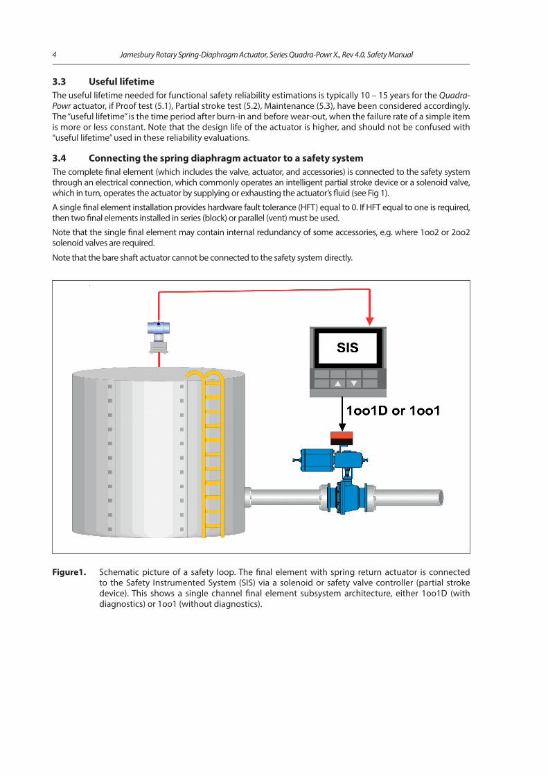
3.4 Connecting the spring diaphragm actuator to a safety systemThe complete final element (which includes the valve, actuator, and accessories) is connected to the safety system through an electrical connection, which commonly operates an intelligent partial stroke device or a solenoid valve, which in turn, operates the actuator by supplying or exhausting the actuator’s fluid (see Fig 1).
A single final element installation provides hardware fault tolerance (HFT) equal to 0. If HFT equal to one is required, then two final elements installed in series (block) or parallel (vent) must be used.
Note that the single final element may contain internal redundancy of some accessories, e.g. where 1oo2 or 2oo2 solenoid valves are required.
Note that the bare shaft actuator cannot be connected to the safety system directly.
Figure1. Schematic picture of a safety loop. The final element with spring return actuator is connected to the Safety Instrumented System (SIS) via a solenoid or safety valve controller (partial stroke device). This shows a single channel final element subsystem architecture, either 1oo1D (with diagnostics) or 1oo1 (without diagnostics).
Jamesbury Rotary Spring-Diaphragm Actuator, Series Quadra-Powr X., Rev 4.0, Safety Manual 5
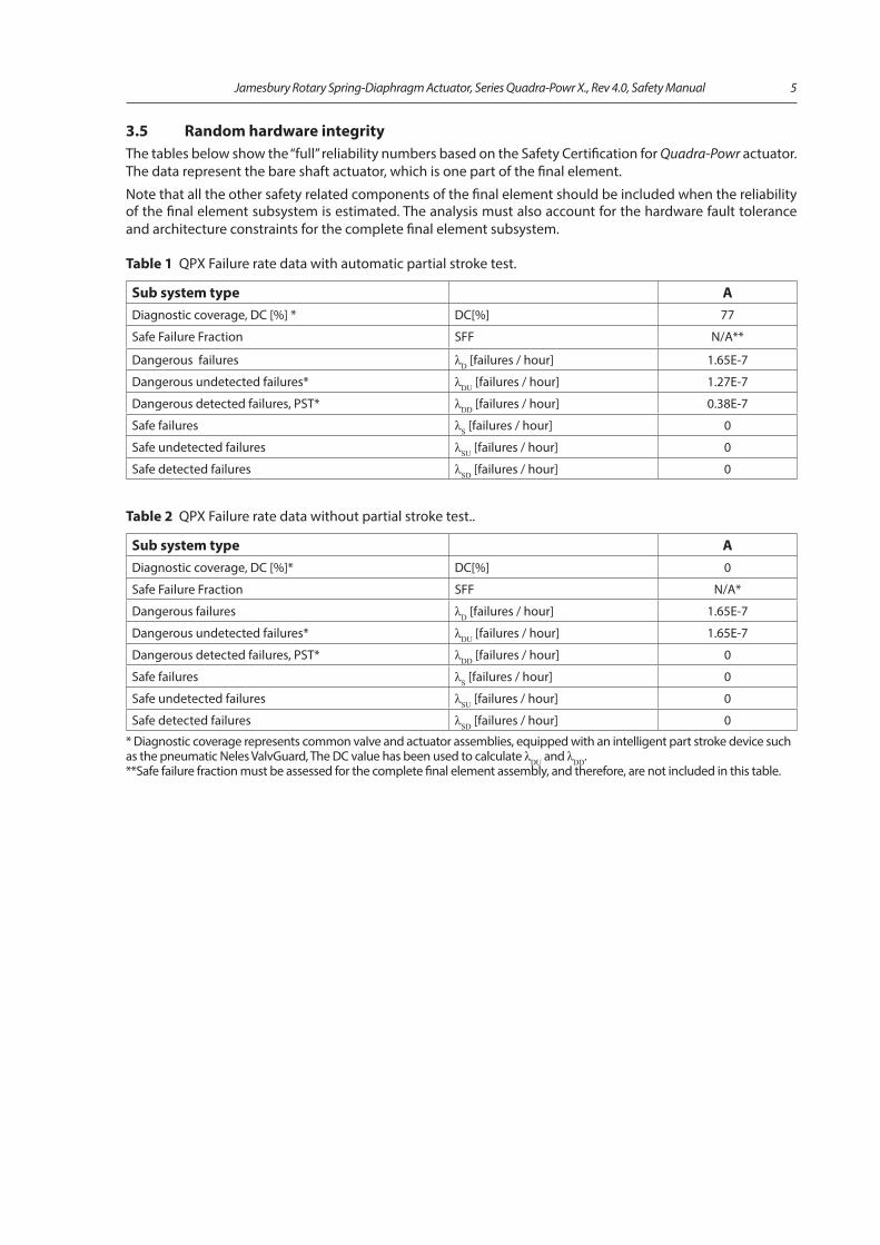
3.5 Random hardware integrity The tables below show the “full” reliability numbers based on the Safety Certification for Quadra-Powr actuator. The data represent the bare shaft actuator, which is one part of the final element.
Note that all the other safety related components of the final element should be included when the reliability of the final element subsystem is estimated. The analysis must also account for the hardware fault tolerance and architecture constraints for the complete final element subsystem.
Table 1 QPX Failure rate data with automatic partial stroke test.
Sub system type ADiagnostic coverage, DC [%] * DC[%] 77
Safe Failure Fraction SFF N/A**
Dangerous failures λD [failures / hour] 1.65E-7
Dangerous undetected failures* λDU [failures / hour] 1.27E-7
Dangerous detected failures, PST* λDD [failures / hour] 0.38E-7
Safe failures λS [failures / hour] 0
Safe undetected failures λSU [failures / hour] 0
Safe detected failures λSD [failures / hour] 0
Table 2 QPX Failure rate data without partial stroke test..
Sub system type ADiagnostic coverage, DC [%]* DC[%] 0
Safe Failure Fraction SFF N/A*
Dangerous failures λD [failures / hour] 1.65E-7
Dangerous undetected failures* λDU [failures / hour] 1.65E-7
Dangerous detected failures, PST* λDD [failures / hour] 0
Safe failures λS [failures / hour] 0
Safe undetected failures λSU [failures / hour] 0
Safe detected failures λSD [failures / hour] 0
* Diagnostic coverage represents common valve and actuator assemblies, equipped with an intelligent part stroke device such as the pneumatic Neles ValvGuard, The DC value has been used to calculate λDU and λDD.**Safe failure fraction must be assessed for the complete final element assembly, and therefore, are not included in this table.
6 Jamesbury Rotary Spring-Diaphragm Actuator, Series Quadra-Powr X., Rev 4.0, Safety Manual
3.6 Systematic integritySystematic integrity requirements according IEC 61508 up to and including Safety Integrity level (SIL) 3 are fulfilled with the required fault tolerance. These requirements include adequate integrity against systematic errors in the product design, and controlling systematic failures in the selection and manufacturing process. Quadra-Powr actuators must not be used in safety integrity functions with higher than the stated SIL level without a proven in use statement or, in some cases, redundant designs.
3.7 Additional informationPersonnel doing the maintenance and testing must be competent to perform the required actions.
All final element components and components shall be operational before startup.
Proof testing should be recorded and documented according to IEC 61508 and maintenance actions done according to Part 5.
Unless the procedures above are properly followed, the reliability data shown in Paragraph 3.5 might not be valid.
4. InstallationThe Jamesbury Quadra-Powr actuator must be installed on the valve according to Metso’s instructions given in the Installation, Maintenance and Operation manual. Possible standards relevant to applications, local requirements, etc should be also considered. Installation must be done by competent persons. In case a bare shaft actuator (not supplied as an assembly by Metso) is to be installed in a valve assembly, the installer is responsible to verify the suitability of all linkage parts (see more details in IMO). It is particularly important to confirm that all components are working properly together.
Incorrect installation may jeopardize the validity of the reliability data given in Paragraph 3.5.
In cases where the complete valve assembly is supplied and shipped by Metso, the complete valve assembly is tested and configured according to Metso internal procedures, except where project specific procedures are used.
5. Operation
5.1 Recommended proof testThe purpose of proof testing is to detect failures of the complete final element subsystem. Metso recommends the following proof test procedure to achieve a proof test coverage factor of 99%.:
• Conduct an initial visual inspection. Check that there are no unauthorized modifications to the SIS valve assembly. Verify that there is no observable deterioration in the SIS valve such as leaks, visible damage, or impurities on the SIS valve.
• Bypass the SIS valve if full stroke could cause an unnecessary process shutdown.• Perform the safety action (full stroke), preferably using the system. Verify that the SIS valve achieves
safe position within the required time specified by the application. Verify also the shutoff tightness for tightness critical applications. Note, that a tightness measurement might require removing the valve from the pipeline. If the valve must be removed from the pipeline, verify proper full stroke operation after re-installation.
• Restore the SIS valve to it’s normal position.• Conduct a final visual inspection. Check that the SIS valve is in the normal position, and verify that all
accessories are operating according the specification for the SIS valve normal operation. Inspect visually that there is no observable deterioration of the SIS valve.
• Record all results and observations into the corresponding database with necessary audit trail information.• Remove the SIS valve bypassing, if used.
5.2 Recommended partial stroke test A partial stroke test is a verified movement of an emergency valve from the normal operating position toward the safe state. Partial stroke testing can be done in most cases while the process is on-stream without disturbing the process. The purpose is to provide early detection of automated block / vent valve failure modes, and to reduce the probability of failure on demand. A partial stroke coverage factor of 77% is assumed.
Metso recommends using the testing capability available with intelligent partial stroke devices such as the pneumatic Neles ValvGuard. In order to obtain the full benefit of diagnostics provided by partial stroke devices, ensure first that the device is calibrated and configured correctly according to the manufacturer’s guidelines.
Jamesbury Rotary Spring-Diaphragm Actuator, Series Quadra-Powr X., Rev 4.0, Safety Manual 7
Before initiating the partial stroke, ensure that the partial stroke will not cause a process hazard. If needed, the possible pressure disturbance can be further estimated by using Metso’s Nelprof valve sizing software.
The required partial stroke test interval may depend on application and targeted SIL level, but test intervals from 1 month to 6 month are generally recommended. Partial stroke size is typically from 10 to 20% of full travel starting from fully open in shutdown service and from 3 to 5 % starting from fully closed in blowdown (vent) service.
Note, that in some valve types such as butterfly valves which have small valve dead angle values, a small amount of flow might occur during a partial stroke in blowdown service. In typical ball valves, the partial stroke test can be done within the valve’s dead angle value, thus maintaining tightness in blowdown service.
A partial stroke test can be initiated either manually or automatically. The test interval is set by the user. The user can be reminded by a partial stroke scheduler system in manual mode, and the test interval is controlled by the intelligent partial stroke test device in the automatic mode. Contact the partial stroke test device manufacturer for more details on how to select and set parameters to control the partial stroke size and frequency.
5.3 MaintenanceAny repair of the Jamesbury Quadra-Powr actuator must be carried out by Metso or competent personnel. Maintenance procedures are given in the IMO. Generally a maintenance interval of 5 years is recommended. With proper maintenance, a maintenance coverage factor of > 99% can be achieved.
After the maintenance is completed, verify the functionality of the actuator including the assembly regarding the safety function in question. Note that all maintenance actions should be recorded.
Metso Service provides the recommended spare part kits defined in the Bills of Material contained in every Instructions, Maintenance and Operation (IMO) manual. The need for parts replacement increases with the number of valve operations done during it’s lifetime and with the severity of service. Only authorized Metso replacement parts should be used.
Soft sealing materials especially are affected by aging, and useful lifetime depends strongly on the application. Therefore, the condition of those components should be checked carefully during proof testing. In optimum operating conditions, the maintenance interval may be extended up to 10 years. The estimated typical time for spare parts change is 0 to 2 times during the valve useful lifetime. Possible problems must be resolved in any case of failure, or doubt observed in proof testing.
6. References[1] IMO-215[2] Technical bulletin A110-4[3] SIL certificate TUV 968/V 1119.00/19[4] SIL report TUV 968/V 1119.00/19[5] IEC 61508 – Parts 1-2 and 4-7:2010[6] Neles ValvGuard IMO 7 VG9H 70 en[7] Neles ValvGuard IMO 7 VG9F 70 en[8] Neles ValvGuard Local Control Panel IMO 7 LCP 9H 70 en
8 Jamesbury Rotary Spring-Diaphragm Actuator, Series Quadra-Powr X., Rev 4.0, Safety Manual
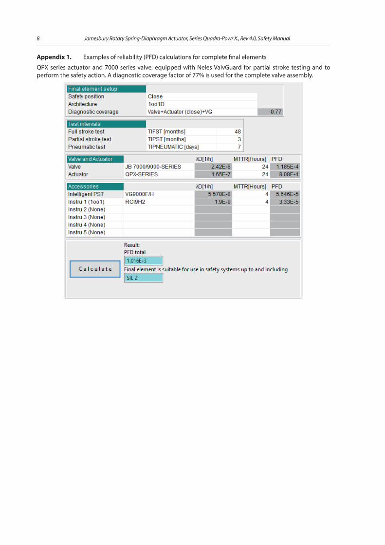
Appendix 1. Examples of reliability (PFD) calculations for complete final elements
QPX series actuator and 7000 series valve, equipped with Neles ValvGuard for partial stroke testing and to perform the safety action. A diagnostic coverage factor of 77% is used for the complete valve assembly.
Jamesbury Rotary Spring-Diaphragm Actuator, Series Quadra-Powr X., Rev 4.0, Safety Manual 9
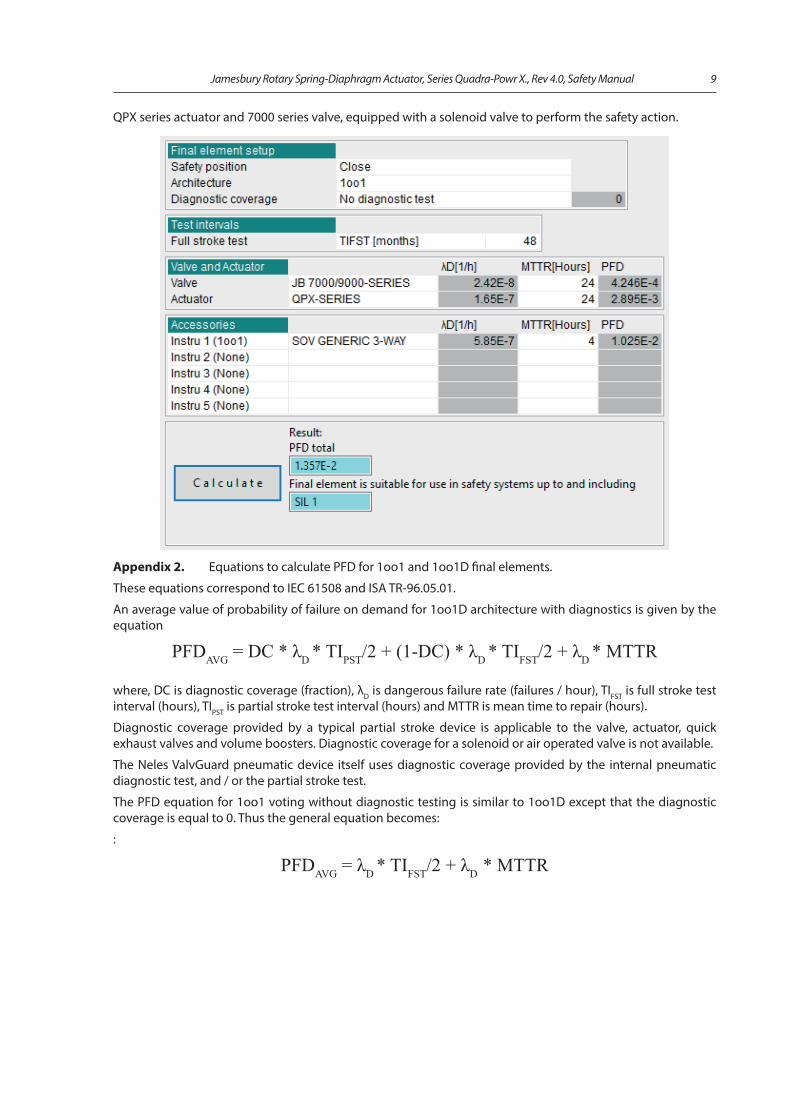
QPX series actuator and 7000 series valve, equipped with a solenoid valve to perform the safety action.
Appendix 2. Equations to calculate PFD for 1oo1 and 1oo1D final elements.
These equations correspond to IEC 61508 and ISA TR-96.05.01.
An average value of probability of failure on demand for 1oo1D architecture with diagnostics is given by the equation
PFDAVG = DC * λD * TIPST/2 + (1-DC) * λD * TIFST/2 + λD * MTTR
where, DC is diagnostic coverage (fraction), λD is dangerous failure rate (failures / hour), TIFST is full stroke test interval (hours), TIPST is partial stroke test interval (hours) and MTTR is mean time to repair (hours).
Diagnostic coverage provided by a typical partial stroke device is applicable to the valve, actuator, quick exhaust valves and volume boosters. Diagnostic coverage for a solenoid or air operated valve is not available.
The Neles ValvGuard pneumatic device itself uses diagnostic coverage provided by the internal pneumatic diagnostic test, and / or the partial stroke test.
The PFD equation for 1oo1 voting without diagnostic testing is similar to 1oo1D except that the diagnostic coverage is equal to 0. Thus the general equation becomes:
:
PFDAVG = λD * TIFST/2 + λD * MTTR
10 Jamesbury Rotary Spring-Diaphragm Actuator, Series Quadra-Powr X., Rev 4.0, Safety Manual
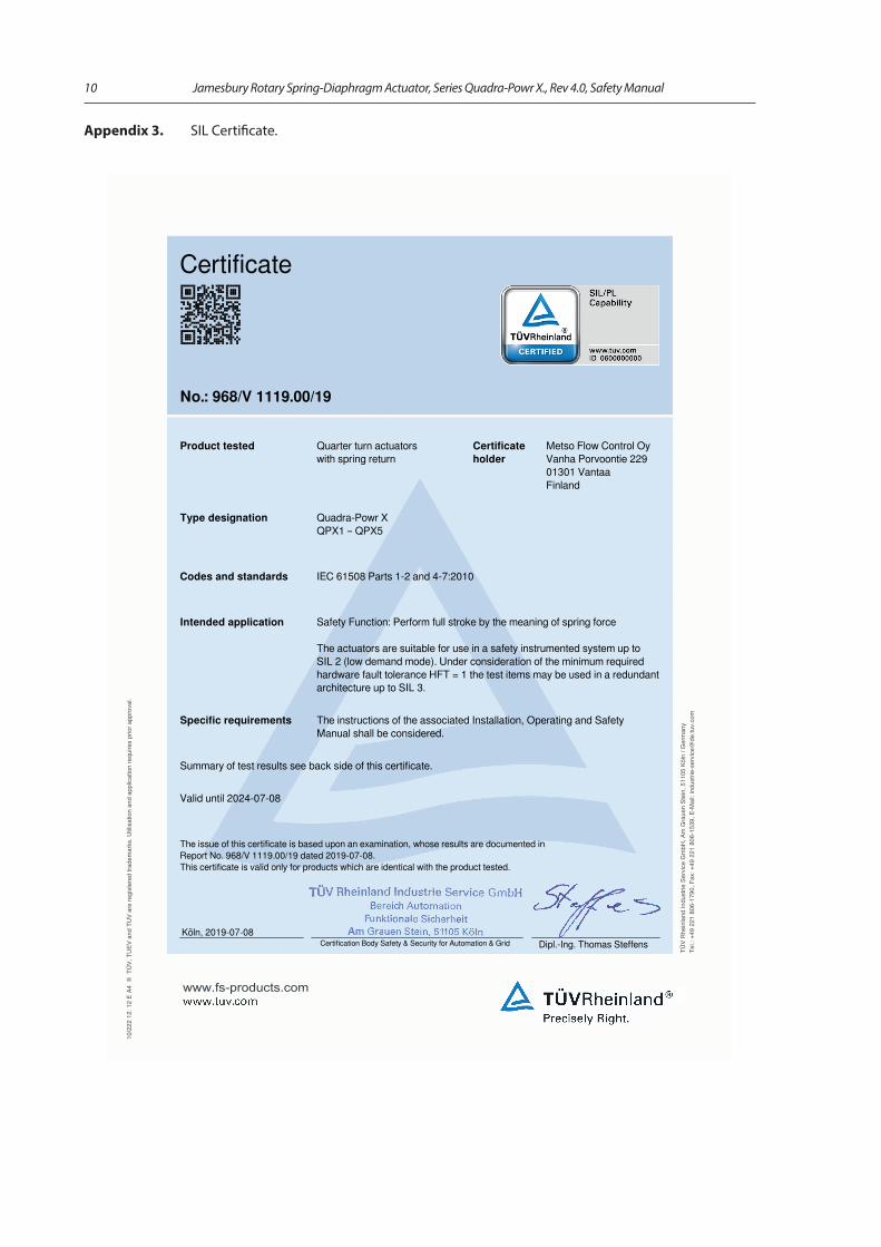
Appendix 3. SIL Certificate.
Certificate
No.: 968/V 1119.00/19
Product tested Quarter turn actuatorswith spring return
Certificateholder
Metso Flow Control OyVanha Porvoontie 22901301 VantaaFinland
Type designation Quadra-Powr XQPX1 – QPX5
Codes and standards IEC 61508 Parts 1-2 and 4-7:2010
Intended application Safety Function: Perform full stroke by the meaning of spring force
The actuators are suitable for use in a safety instrumented system up toSIL 2 (low demand mode). Under consideration of the minimum requiredhardware fault tolerance HFT = 1 the test items may be used in a redundantarchitecture up to SIL 3.
Specific requirements The instructions of the associated Installation, Operating and SafetyManual shall be considered.
Summary of test results see back side of this certificate.
Valid until 2024-07-08
The issue of this certificate is based upon an examination, whose results are documented inReport No. 968/V 1119.00/19 dated 2019-07-08.This certificate is valid only for products which are identical with the product tested.
Certification Body Safety & Security for Automation & Grid
Dipl.-Ing. Thomas Steffens
Köln, 2019-07-08
10/2
22 1
2. 1
2 E
A4 ®
TÜ
V, T
UEV
and
TU
V ar
e re
gist
ered
trad
emar
ks. U
tilis
atio
n an
d ap
plic
atio
n re
quire
s pr
ior a
ppro
val.
TÜV
Rhe
inla
nd In
dust
rie S
ervi
ce G
mbH
, Am
Gra
uen
Stei
n, 5
1105
Köl
n / G
erm
any
Tel.:
+49
221
806
-179
0, F
ax: +
49 2
21 8
06-1
539,
E-M
ail:
indu
strie
-ser
vice
@de
.tuv.
com
www.fs-products.com

Jamesbury Rotary Spring-Diaphragm Actuator, Series Quadra-Powr X., Rev 4.0, Safety Manual 11

Metso Flow Control Inc.
Europe, Vanha Porvoontie 229, P.O. Box 304, FI-01301 Vantaa, Finland. Tel. +358 20 483 150. Fax +358 20 483 151North America, 44 Bowditch Drive, P.O. Box 8044, Shrewsbury, M A 01545, USA. Tel. +1 508 852 0200. Fax +1 508 852 8172
South America, Av. Independéncia, 2500-Iporanga, 18087-101, Sorocaba-São Paulo, Brazil. Tel. +55 15 2102 9700. Fax +55 15 2102 9748 Asia Paci�c, 238B Thomson Road, #17-01 Novena Square Tower B, Singapore 307685. Tel. +65 6511 1011. Fax +65 6250 0830
China, 11/F, China Youth Plaza, No.19 North Rd of East 3rd Ring Rd, Chaoyang District, Beijing 100020, China. Tel. +86 10 6566 6600. Fax +86 10 6566 2583Middle East, Roundabout 8, Unit AB-07, P.O. Box 17175, Jebel Ali Freezone, Dubai, United Arab Emirates. Tel. +971 4 883 6974. Fax +971 4 883 6836
www.metso.com/valves
12 Jamesbury Pneumatic Rack and Pinion Actuator, Valv-Powr Series VPVL, Rev 3.0, Safety Manual