Embed Size (px)
Citation preview
Jan. 2011 Computer Architecture, Instruction-Set Architecture Slide 1
Part IIInstruction-Set Architecture
Jan. 2011 Computer Architecture, Instruction-Set Architecture Slide 2
About This Presentation
This presentation is intended to support the use of the textbook Computer Architecture: From Microprocessors to Supercomputers, Oxford University Press, 2005, ISBN 0-19-515455-X. It is updated regularly by the author as part of his teaching of the upper-division course ECE 154, Introduction to Computer Architecture, at the University of California, Santa Barbara. Instructors can use these slides freely in classroom teaching and for other educational purposes. Any other use is strictly prohibited. ©
Behrooz Parhami
Edition Released Revised Revised Revised Revised
First June 2003 July 2004 June 2005 Mar. 2006 Jan. 2007
Jan. 2008 Jan. 2009 Jan. 2011
Jan. 2011 Computer Architecture, Instruction-Set Architecture Slide 3
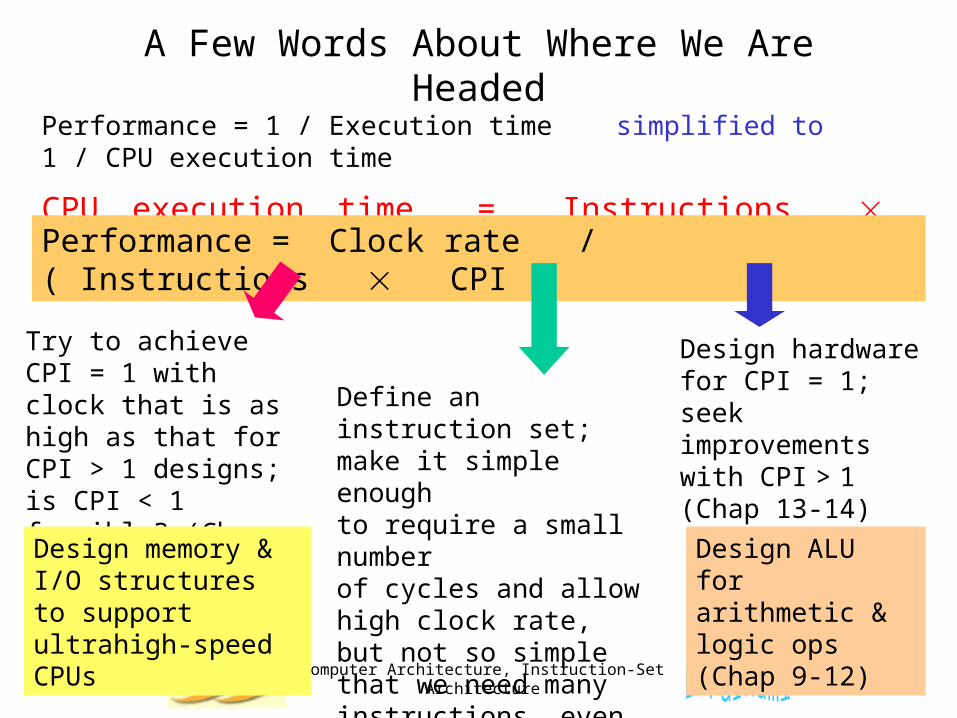
A Few Words About Where We Are Headed
Performance = 1 / Execution time simplified to 1 / CPU execution time
CPU execution time = Instructions CPI / (Clock rate)
Performance = Clock rate / ( Instructions CPI )
Define an instruction set;make it simple enough to require a small number of cycles and allow high clock rate, but not so simple that we need many instructions, even for very simple tasks (Chap 5-8)
Design hardware for CPI = 1; seek improvements with CPI > 1 (Chap 13-14)
Design ALU for arithmetic & logic ops (Chap 9-12)
Try to achieve CPI = 1 with clock that is as high as that for CPI > 1 designs; is CPI < 1 feasible? (Chap 15-16)
Design memory & I/O structures to support ultrahigh-speed CPUs
Jan. 2011 Computer Architecture, Instruction-Set Architecture Slide 4
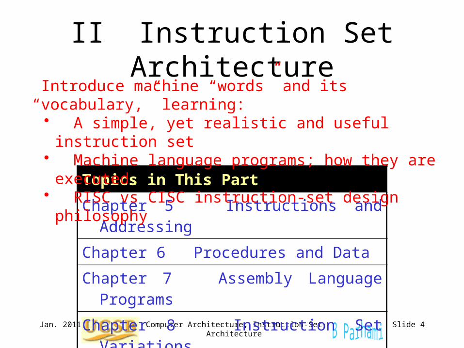
II Instruction Set Architecture
Topics in This Part
Chapter 5 Instructions and Addressing
Chapter 6 Procedures and Data
Chapter 7 Assembly Language Programs
Chapter 8 Instruction Set Variations
Introduce machine “words” and its “vocabulary,” learning:• A simple, yet realistic and useful instruction set• Machine language programs; how they are executed• RISC vs CISC instruction-set design philosophy
Jan. 2011 Computer Architecture, Instruction-Set Architecture Slide 5
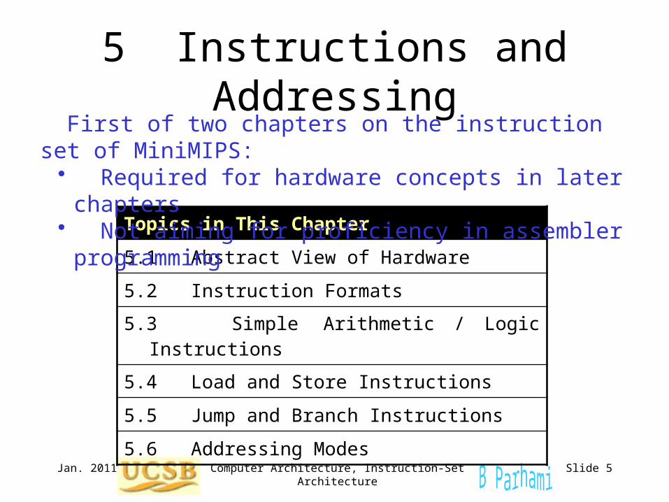
5 Instructions and Addressing
Topics in This Chapter
5.1 Abstract View of Hardware
5.2 Instruction Formats
5.3 Simple Arithmetic / Logic Instructions
5.4 Load and Store Instructions
5.5 Jump and Branch Instructions
5.6 Addressing Modes
First of two chapters on the instruction set of MiniMIPS:• Required for hardware concepts in later chapters• Not aiming for proficiency in assembler programming
Feb. 2011 Computer Architecture, Data Path and Control Slide 6
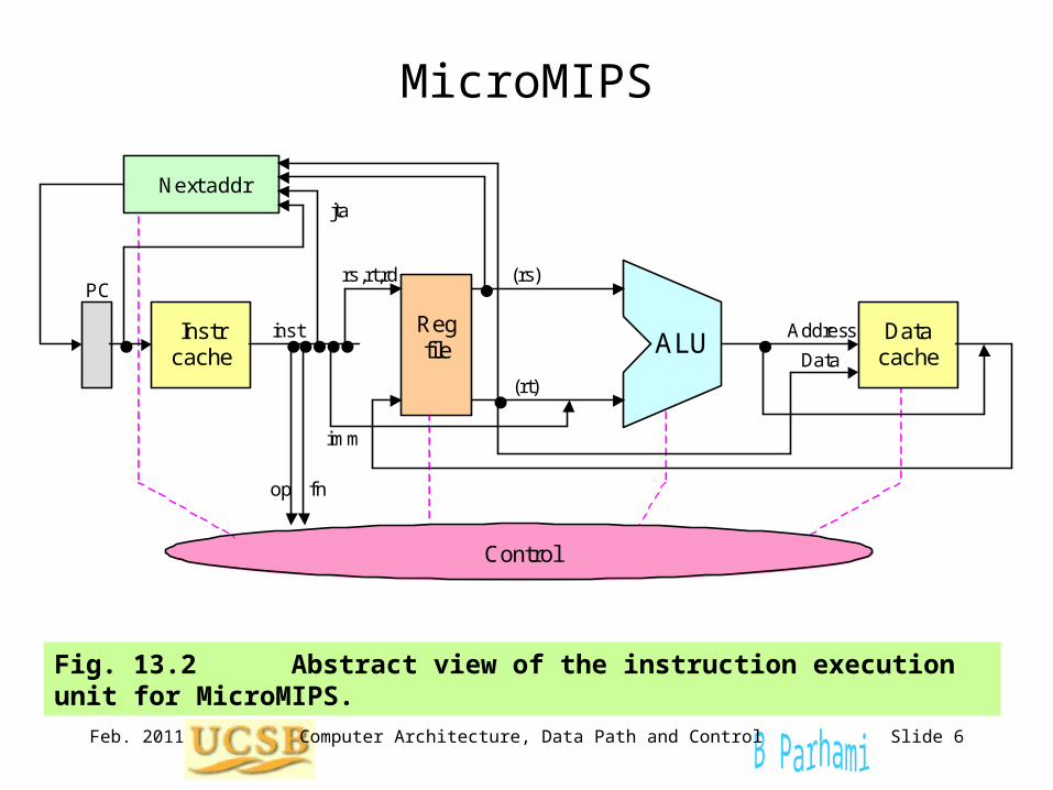
MicroMIPS
Fig. 13.2 Abstract view of the instruction execution unit for MicroMIPS. ALU
Data cache
Instr cache
Next addr
Control
Reg file
op
jta
fn
inst
imm
rs,rt,rd (rs)
(rt)
Address
Data
PC
Jan. 2011 Computer Architecture, Instruction-Set Architecture Slide 7
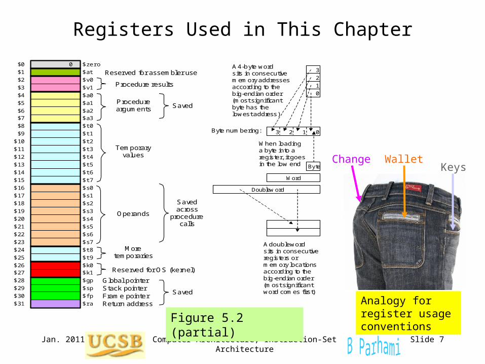
Registers Used in This Chapter
Figure 5.2 (partial)
Temporary values
More temporaries
Operands
Global pointer Stack pointer Frame pointer Return address
Saved
Saved Procedure arguments
Saved across
procedure calls
Procedure results
Reserved for assembler use
Reserved for OS (kernel)
$0 $1 $2 $3 $4 $5 $6 $7 $8 $9 $10 $11 $12 $13 $14 $15 $16 $17 $18 $19 $20 $21 $22 $23 $24 $25 $26 $27 $28 $29 $30 $31
0
$zero
$t0
$t2
$t4
$t6
$t1
$t3
$t5
$t7 $s0
$s2
$s4
$s6
$s1
$s3
$s5
$s7
$t8 $t9
$gp
$sp $fp $ra
$at
$k0 $k1
$v0
$a0
$a2
$v1
$a1
$a3
A doubleword sits in consecutive registers or memory locations according to the big-endian order (most significant word comes first)
When loading a byte into a register, it goes in the low end Byte
Word
Doublew ord
Byte numbering: 0 1 2 3
3
2
1
0
A 4-byte word sits in consecutive memory addresses according to the big-endian order (most significant byte has the lowest address)
WalletKeys
Change
Analogy for register usage conventions
Jan. 2011 Computer Architecture, Instruction-Set Architecture Slide 8
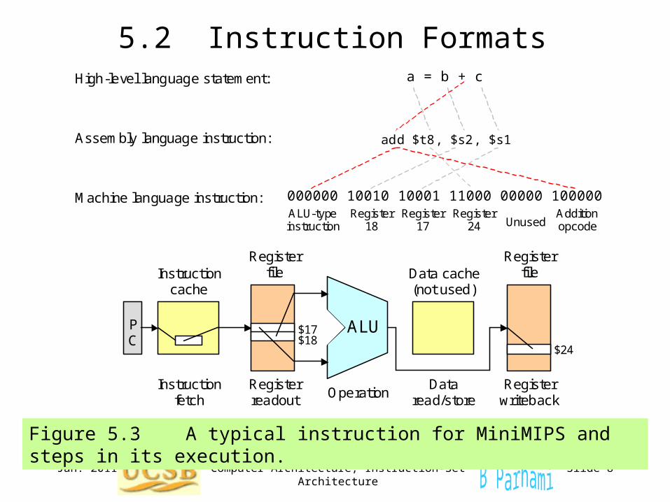
5.2 Instruction Formats
Figure 5.3 A typical instruction for MiniMIPS and steps in its execution.
Assembly language instruction:
Machine language instruction:
High-level language statement:
000000 10010 10001 11000 00000 100000
add $t8, $s2, $s1
a = b + c
ALU-type instruction
Register 18
Register 17
Register 24 Unused
Addition opcode
ALU
Instruction fetch
Register readout
Operation
Data read/store
Register writeback
Register file
Instruction
cache
Data cache (not used)
Register file
P C
$17 $18
$24
Jan. 2011 Computer Architecture, Instruction-Set Architecture Slide 9
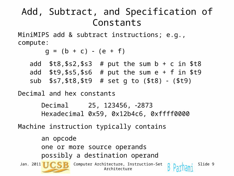
Add, Subtract, and Specification of Constants
MiniMIPS add & subtract instructions; e.g., compute: g = (b + c) (e + f)
add $t8,$s2,$s3 # put the sum b + c in $t8 add $t9,$s5,$s6 # put the sum e + f in $t9 sub $s7,$t8,$t9 # set g to ($t8) ($t9)
Decimal and hex constants
Decimal 25, 123456, 2873 Hexadecimal 0x59, 0x12b4c6, 0xffff0000
Machine instruction typically contains
an opcode one or more source operands possibly a destination operand
Jan. 2011 Computer Architecture, Instruction-Set Architecture Slide 10
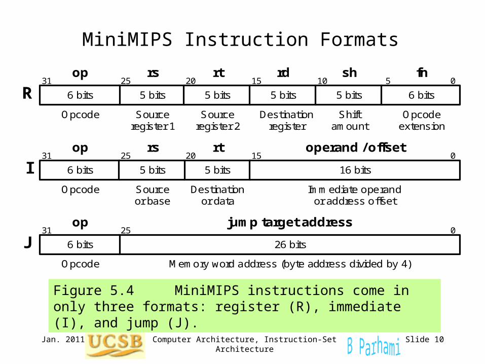
MiniMIPS Instruction Formats
Figure 5.4 MiniMIPS instructions come in only three formats: register (R), immediate (I), and jump (J).
5 bits 5 bits
31 25 20 15 0
Opcode Source register 1
Source register 2
op rs rt
R 6 bits 5 bits
rd
5 bits
sh
6 bits
10 5 fn
Destination register
Shift amount
Opcode extension
Immediate operand or address offset
31 25 20 15 0
Opcode Destination or data
Source or base
op rs rt operand / offset
I 5 bits 6 bits 16 bits 5 bits
0 0 0 0 0 0 0 0 0 0 0 1 1 1 1 1 1 0 0 0 0 0 0 0 0 0
31 0
Opcode
op jump target address
J Memory word address (byte address divided by 4)
26 bits
25
6 bits
Jan. 2011 Computer Architecture, Instruction-Set Architecture Slide 11
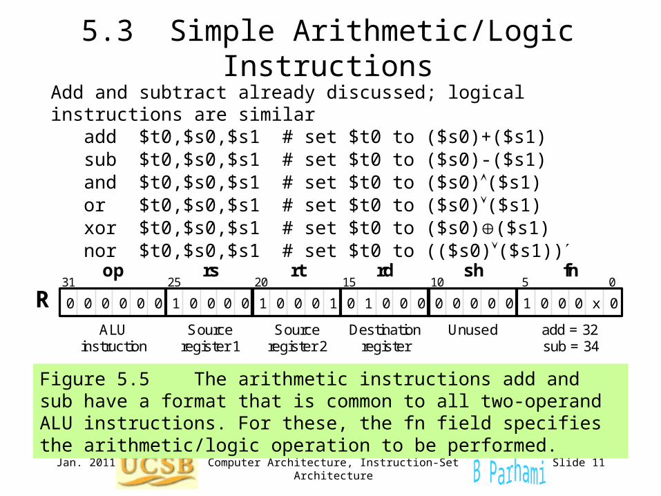
5.3 Simple Arithmetic/Logic Instructions
Figure 5.5 The arithmetic instructions add and sub have a format that is common to all two-operand ALU instructions. For these, the fn field specifies the arithmetic/logic operation to be performed.
0 0 0 0 0 0 0 0 0 0 0 0 0 0 0 1 x 0 0 1 1 1 1 0 0 0 0 0 0 0 0 0
31 25 20 15 0
ALU instruction
Source register 1
Source register 2
op rs rt
R rd sh
10 5 fn
Destination register
Unused add = 32 sub = 34
Add and subtract already discussed; logical instructions are similar
add $t0,$s0,$s1 # set $t0 to ($s0)+($s1) sub $t0,$s0,$s1 # set $t0 to ($s0)-($s1) and $t0,$s0,$s1 # set $t0 to ($s0)($s1) or $t0,$s0,$s1 # set $t0 to ($s0)($s1) xor $t0,$s0,$s1 # set $t0 to ($s0)($s1) nor $t0,$s0,$s1 # set $t0 to (($s0)($s1))
Jan. 2011 Computer Architecture, Instruction-Set Architecture Slide 12
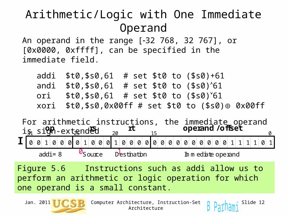
Arithmetic/Logic with One Immediate Operand
Figure 5.6 Instructions such as addi allow us to perform an arithmetic or logic operation for which one operand is a small constant.
0 0 0 0 0 0 0 0 0 0 0 0 0 0 1 1 1 1 1 0 0 1 1 0 0 0 0 0 0 0 0
31 25 20 15 0
addi = 8 Destination Source Immediate operand
op rs rt operand / offset
I 1
An operand in the range [-32 768, 32 767], or [0x0000, 0xffff], can be specified in the immediate field.
addi $t0,$s0,61 # set $t0 to ($s0)+61 andi $t0,$s0,61 # set $t0 to ($s0)61 ori $t0,$s0,61 # set $t0 to ($s0)61 xori $t0,$s0,0x00ff # set $t0 to ($s0) 0x00ff
For arithmetic instructions, the immediate operand is sign-extended
1 0 0 1
Jan. 2011 Computer Architecture, Instruction-Set Architecture Slide 13
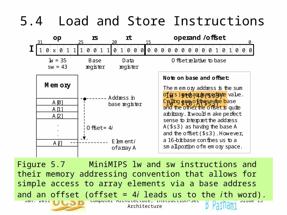
5.4 Load and Store Instructions
Figure 5.7 MiniMIPS lw and sw instructions and their memory addressing convention that allows for simple access to array elements
via a base address and an offset (offset = 4i leads us to the i th word).
0 0 0 0 0 0 0 0 0 0 0 0 1 0 0 x 1 0 0 0 0 0 0
31 25 20 15 0
lw = 35 sw = 43
Base register
Data register
Offset relative to base
op rs rt operand / offset
I 1 1 0 0 1 1 1 1 1
A[0] A[1] A[2]
A[i]
Address in base register
Offset = 4i
.
.
.
Memory
Element i of array A
Note on base and offset: The memory address is the sum of (rs) and an immediate value. Calling one of these the base and the other the offset is quite arbitrary. It would make perfect sense to interpret the address A($s3) as having the base A and the offset ($s3). However, a 16-bit base confines us to a small portion of memory space.
lw $t0,40($s3)lw $t0,A($s3)
Jan. 2011 Computer Architecture, Instruction-Set Architecture Slide 14
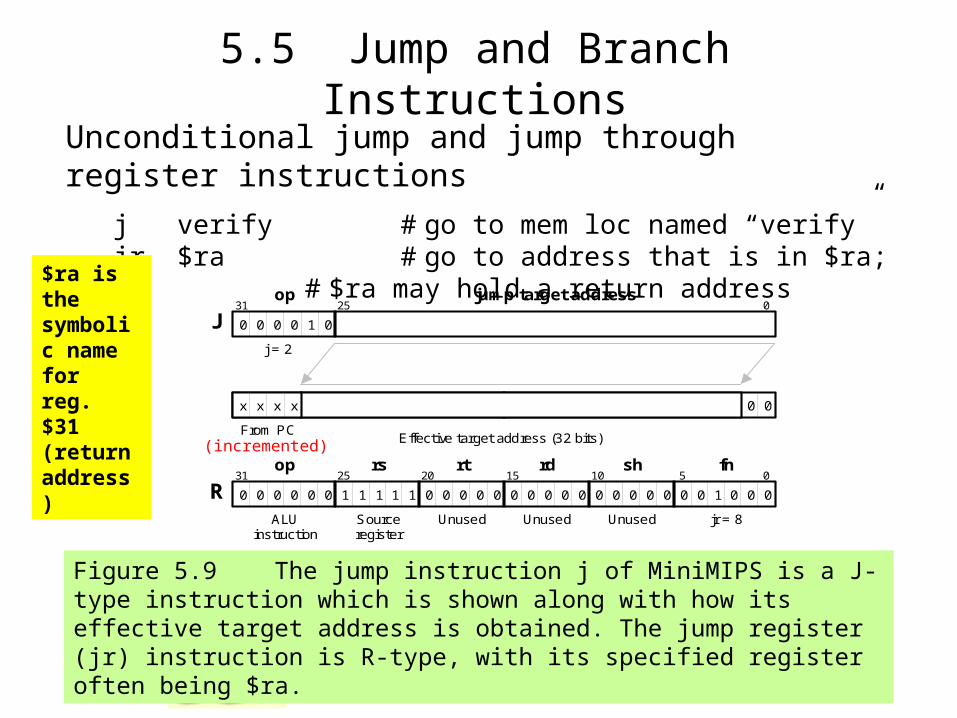
5.5 Jump and Branch Instructions
Unconditional jump and jump through register instructions
j verify # go to mem loc named “verify” jr $ra # go to address that is in $ra;
# $ra may hold a return address
Figure 5.9 The jump instruction j of MiniMIPS is a J-type instruction which is shown along with how its effective target address is obtained. The jump register (jr) instruction is R-type, with its specified register often being $ra.
0
0 0 0 0 0 0 0 1 1 1 1 1 0 0 0 0 0 0 0 0 0 0 0 0 0 0 0 0
0 0 0 0 0 0 0 0 0 0 0 1 1 1 1 1 0 0 1 0 0 0 0 0 0 0 0 0
31 0
j = 2
op jump target address
J
Effective target address (32 bits)
25
From PC
0 0
x x x x
0 0 0 1 1 1 1 0 0 0 0 0 0 0 0 0 0 0 0 0 0 0 0 0 0 0 1 1 0 0 0 0
31 25 20 15 0
ALU instruction
Source register
Unused
op rs rt
R rd sh
10 5 fn
Unused Unused jr = 8
$ra is the symbolic name for reg. $31 (return address)
(incremented)
Jan. 2011 Computer Architecture, Instruction-Set Architecture Slide 15
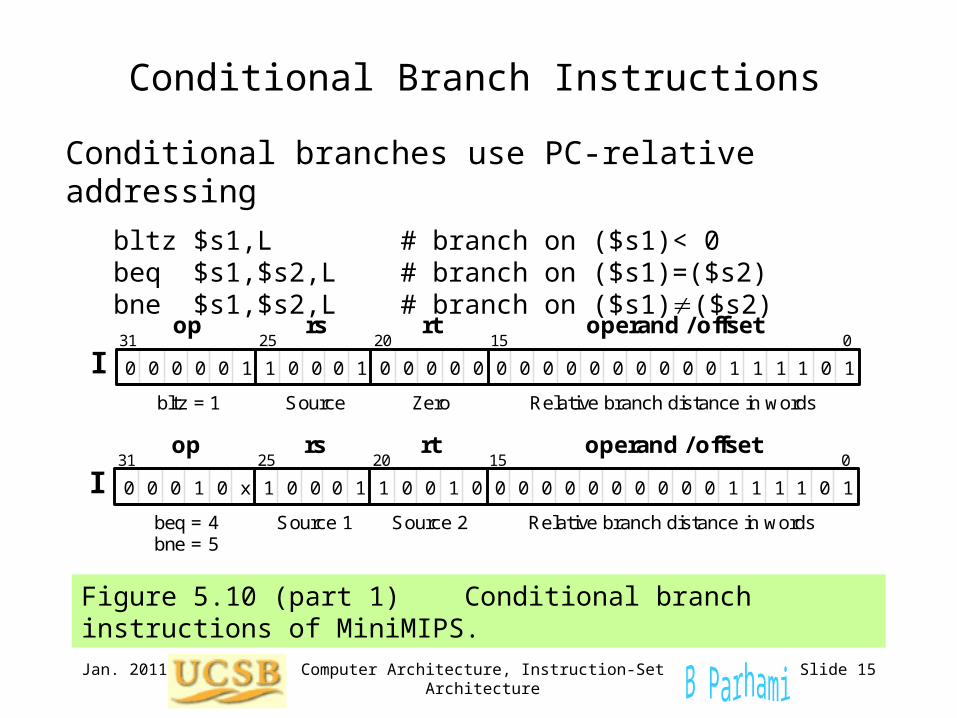
Conditional Branch Instructions
Figure 5.10 (part 1) Conditional branch instructions of MiniMIPS.
Conditional branches use PC-relative addressing
bltz $s1,L # branch on ($s1)< 0 beq $s1,$s2,L # branch on ($s1)=($s2) bne $s1,$s2,L # branch on ($s1)($s2)
0 1 0 0 0 0 0 0 0 0 0 0 0 0 0 0 1 1 1 1 1 0 0 1 1 0 0 0 0 0 0
31 25 20 15 0
bltz = 1 Zero Source Relative branch distance in words
op rs rt operand / offset
I 0
1 1 0 0 x 0 0 0 0 0 0 0 0 0 0 0 1 1 1 1 1 0 0 1 1 0 0 0 0 0 0
31 25 20 15 0
beq = 4 bne = 5
Source 2 Source 1 Relative branch distance in words
op rs rt operand / offset
I 1
Jan. 2011 Computer Architecture, Instruction-Set Architecture Slide 16
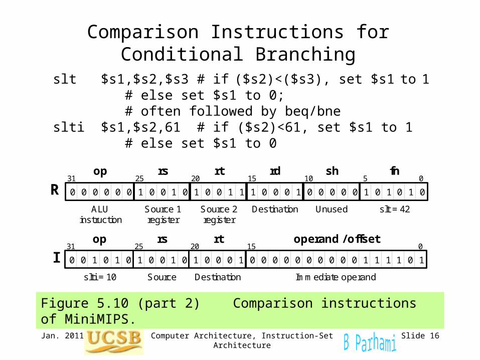
Comparison Instructions for Conditional Branching
Figure 5.10 (part 2) Comparison instructions of MiniMIPS.
slt $s1,$s2,$s3 # if ($s2)<($s3), set $s1 to 1 # else set $s1 to 0;
# often followed by beq/bne slti $s1,$s2,61 # if ($s2)<61, set $s1 to 1 # else set $s1 to 0
1 1 1 0 1 1 1 0 0 0 1 1 0 0 0 0 0 0 0 0 0 0 0 0 0 0 0 0 1 1 0 0
31 25 20 15 0
ALU instruction
Source 1 register
Source 2 register
op rs rt
R rd sh
10 5 fn
Destination Unused slt = 42
1 1 1 0 0 0 0 0 0 0 0 0 0 0 0 0 1 1 1 1 1 0 0 1 1 0 0 0 0 0 0
31 25 20 15 0
slti = 10 Destination Source Immediate operand
op rs rt operand / offset
I 1
Jan. 2011 Computer Architecture, Instruction-Set Architecture Slide 17
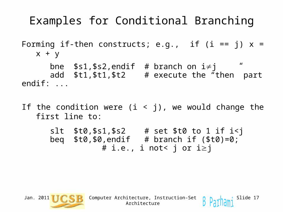
Examples for Conditional Branching
Forming if-then constructs; e.g., if (i == j) x = x + y
bne $s1,$s2,endif # branch on ij add $t1,$t1,$t2 # execute the “then”
partendif: ...
If the condition were (i < j), we would change the first line to:
slt $t0,$s1,$s2 # set $t0 to 1 if i<j beq $t0,$0,endif # branch if ($t0)=0;
# i.e., i not< j or ij
Jan. 2011 Computer Architecture, Instruction-Set Architecture Slide 18
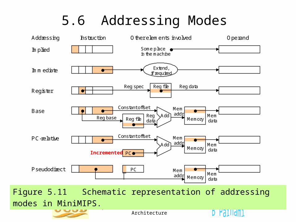
5.6 Addressing Modes
Figure 5.11 Schematic representation of addressing modes in MiniMIPS.
Addressing Instruction Other elements involved Operand
Implied
Immediate
Register
Base
PC-relative
Pseudodirect
Some place in the machine
Extend, if required
Reg file Reg spec Reg data
Memory Add
Reg file
Mem addr
Constant offset
Reg base Reg data
Mem data
Add
PC
Constant offset
Memory
Mem addr Mem
data
Memory Mem data
PC Mem addr
Incremented
Jan. 2011 Computer Architecture, Instruction-Set Architecture Slide 19
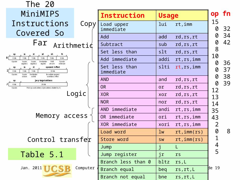
The 20 MiniMIPS Instructions
Covered So Far
Instruction UsageLoad upper immediate lui rt,imm
Add add rd,rs,rt
Subtract sub rd,rs,rt
Set less than slt rd,rs,rt
Add immediate addi rt,rs,imm
Set less than immediate slti rt,rs,imm
AND and rd,rs,rt
OR or rd,rs,rt
XOR xor rd,rs,rt
NOR nor rd,rs,rt
AND immediate andi rt,rs,imm
OR immediate ori rt,rs,imm
XOR immediate xori rt,rs,imm
Load word lw rt,imm(rs)
Store word sw rt,imm(rs)
Jump j L
Jump register jr rs
Branch less than 0 bltz rs,L
Branch equal beq rs,rt,L
Branch not equal bne rs,rt,L
Copy
Control transfer
Logic
Arithmetic
Memory access
op15
0008
100000
1213143543
20145
fn
323442
36373839
8 Table 5.1
5 bits 5 bits
31 25 20 15 0
Opcode Source register 1
Source register 2
op rs rt
R 6 bits 5 bits
rd
5 bits
sh
6 bits
10 5 fn
Destination register
Shift amount
Opcode extension
Immediate operand or address offset
31 25 20 15 0
Opcode Destination or data
Source or base
op rs rt operand / offset
I 5 bits 6 bits 16 bits 5 bits
0 0 0 0 0 0 0 0 0 0 0 1 1 1 1 1 1 0 0 0 0 0 0 0 0 0
31 0
Opcode
op jump target address
J Memory word address (byte address divided by 4)
26 bits
25
6 bits
Jan. 2011 Computer Architecture, Instruction-Set Architecture Slide 20
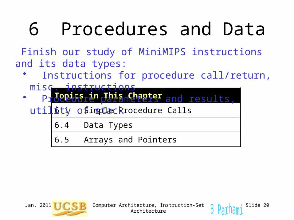
6 Procedures and Data
Topics in This Chapter
6.1 Simple Procedure Calls
6.4 Data Types
6.5 Arrays and Pointers
Finish our study of MiniMIPS instructions and its data types:• Instructions for procedure call/return, misc. instructions• Procedure parameters and results, utility of stack
Jan. 2011 Computer Architecture, Instruction-Set Architecture Slide 21
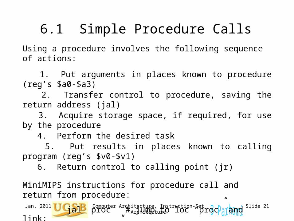
6.1 Simple Procedure CallsUsing a procedure involves the following sequence of actions:
1. Put arguments in places known to procedure (reg’s $a0-$a3) 2. Transfer control to procedure, saving the return address (jal) 3. Acquire storage space, if required, for use by the procedure 4. Perform the desired task 5. Put results in places known to calling program (reg’s $v0-$v1) 6. Return control to calling point (jr)
MiniMIPS instructions for procedure call and return from procedure:
jal proc # jump to loc “proc” and link; # “link” means “save the return
# address” (PC)+4 in $ra ($31)
jr rs # go to loc addressed by rs
Jan. 2011 Computer Architecture, Instruction-Set Architecture Slide 22
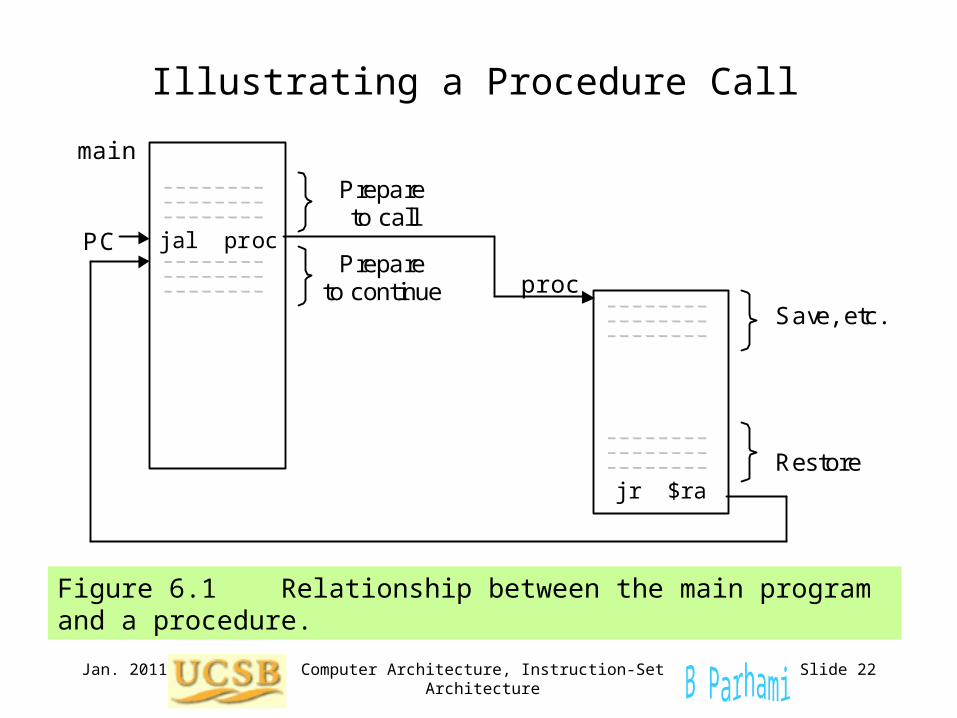
Illustrating a Procedure Call
Figure 6.1 Relationship between the main program and a procedure.
jal proc
jr $ra
proc Save, etc.
Restore
PC Prepare
to continue
Prepare to call
main
Jan. 2011 Computer Architecture, Instruction-Set Architecture Slide 23
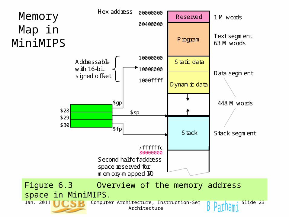
Memory Map in
MiniMIPS
Figure 6.3 Overview of the memory address space in MiniMIPS.
Reserved
Program
Stack
1 M words
Hex address
10008000
1000ffff
10000000
00000000
00400000
7ffffffc
Text segment 63 M words
Data segment
Stack segment
Static data
Dynamic data
$gp
$sp
$fp
448 M words
Second half of address space reserved for memory-mapped I/O
$28 $29 $30
Addressable with 16-bit signed offset
80000000
Jan. 2011 Computer Architecture, Instruction-Set Architecture Slide 24
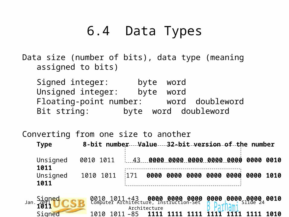
6.4 Data Types
Data size (number of bits), data type (meaning assigned to bits)
Signed integer: byte wordUnsigned integer: byte wordFloating-point number: word doublewordBit string: byte word doubleword
Converting from one size to another
Type 8-bit number Value 32-bit version of the number
Unsigned 0010 1011 43 0000 0000 0000 0000 0000 0000 0010 1011Unsigned 1010 1011 171 0000 0000 0000 0000 0000 0000 1010 1011
Signed 0010 1011 +43 0000 0000 0000 0000 0000 0000 0010 1011Signed 1010 1011 –85 1111 1111 1111 1111 1111 1111 1010 1011
Jan. 2011 Computer Architecture, Instruction-Set Architecture Slide 25
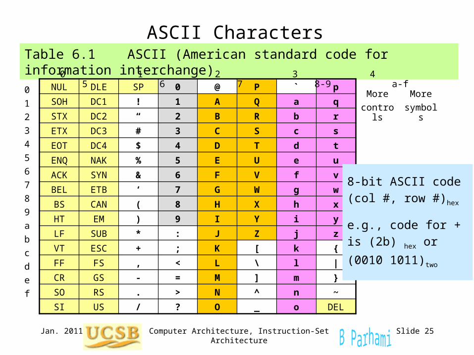
ASCII CharactersTable 6.1 ASCII (American standard code for information interchange)
NUL DLE SP 0 @ P ` p
SOH DC1 ! 1 A Q a q
STX DC2 “ 2 B R b r
ETX DC3 # 3 C S c s
EOT DC4 $ 4 D T d t
ENQ NAK % 5 E U e u
ACK SYN & 6 F V f v
BEL ETB ‘ 7 G W g w
BS CAN ( 8 H X h x
HT EM ) 9 I Y i y
LF SUB * : J Z j z
VT ESC + ; K [ k {
FF FS , < L \ l |
CR GS - = M ] m }
SO RS . > N ^ n ~
SI US / ? O _ o DEL
0
1
2
3
4
5
6
7
8
9
a
b
c
d
e
f
0 1 2 3 4 5 6 7 8-9 a-f
More
controls
More
symbols
8-bit ASCII code
(col #, row #)hex
e.g., code for +
is (2b) hex or
(0010 1011)two
Jan. 2011 Computer Architecture, Instruction-Set Architecture Slide 26
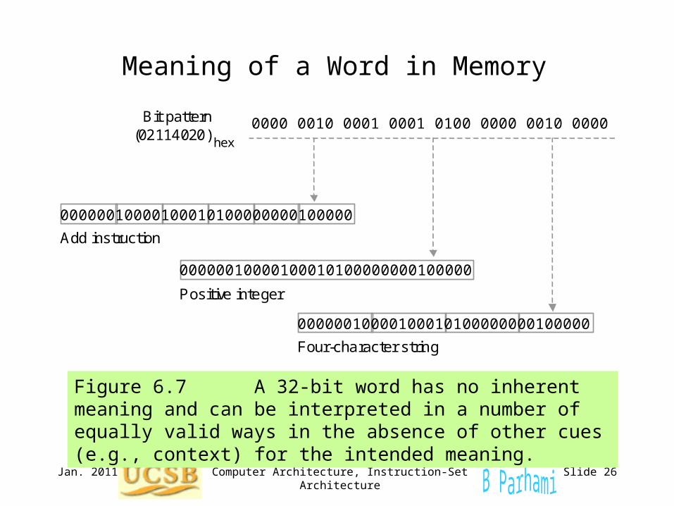
Meaning of a Word in Memory
Figure 6.7 A 32-bit word has no inherent meaning and can be interpreted in a number of equally valid ways in the absence of other cues (e.g., context) for the intended meaning.
0000 0010 0001 0001 0100 0000 0010 0000
Positive integer
Four-character string
Add instruction
Bit pattern (02114020) hex
00000010000100010100000000100000
00000010000100010100000000100000
00000010000100010100000000100000
Jan. 2011 Computer Architecture, Instruction-Set Architecture Slide 27
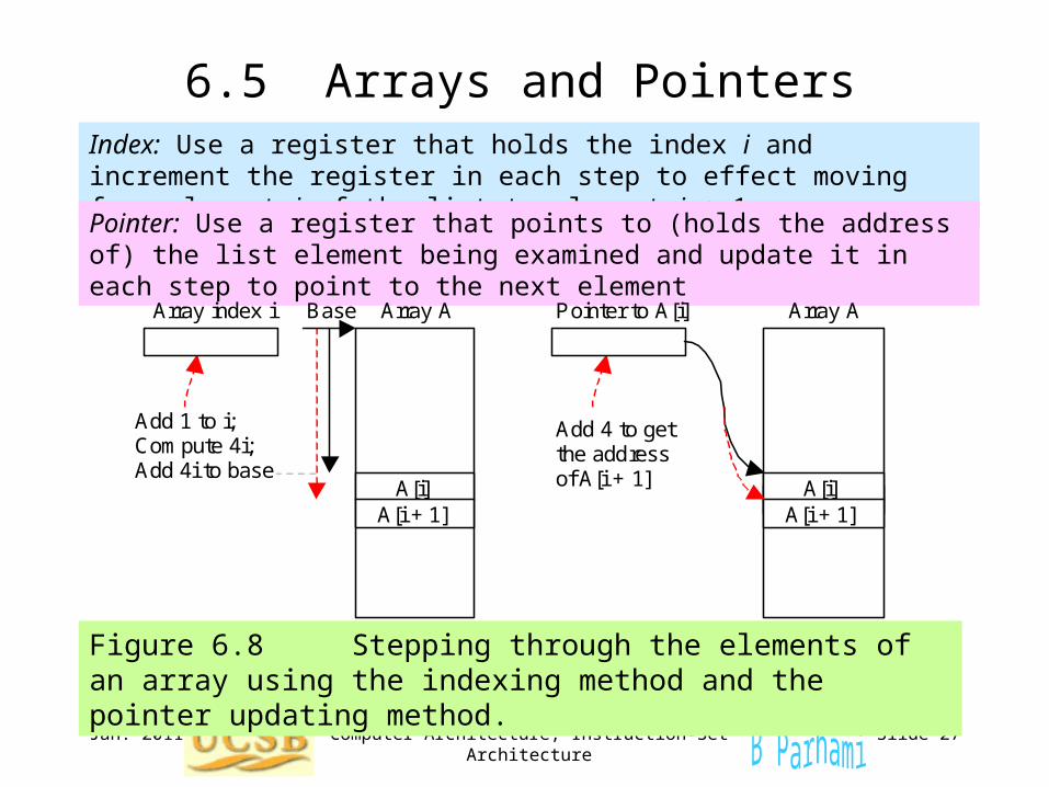
6.5 Arrays and PointersIndex: Use a register that holds the index i and increment the register in each step to effect moving from element i of the list to element i + 1
Pointer: Use a register that points to (holds the address of) the list element being examined and update it in each step to point to the next element
Add 4 to get the address of A[i + 1]
Pointer to A[i] Array index i
Add 1 to i; Compute 4i; Add 4i to base
A[i] A[i + 1]
A[i] A[i + 1]
Base Array A Array A
Figure 6.8 Stepping through the elements of an array using the indexing method and the pointer updating method.

Feb. 2011 Computer Architecture, Data Path and Control Slide 28
MicroMIPS
Fig. 13.2 Abstract view of the instruction execution unit for MicroMIPS. ALU
Data cache
Instr cache
Next addr
Control
Reg file
op
jta
fn
inst
imm
rs,rt,rd (rs)
(rt)
Address
Data
PC
Feb. 2011 Computer Architecture, Data Path and Control Slide 29
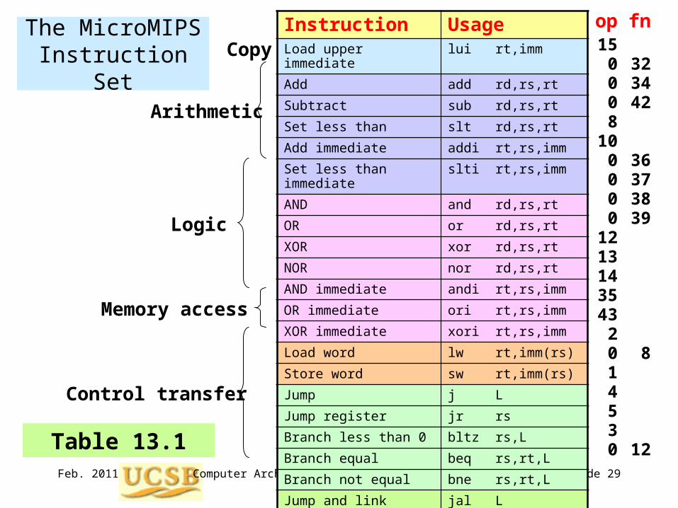
The MicroMIPS Instruction Set
Instruction UsageLoad upper immediate lui rt,imm
Add add rd,rs,rt
Subtract sub rd,rs,rt
Set less than slt rd,rs,rt
Add immediate addi rt,rs,imm
Set less than immediate slti rt,rs,imm
AND and rd,rs,rt
OR or rd,rs,rt
XOR xor rd,rs,rt
NOR nor rd,rs,rt
AND immediate andi rt,rs,imm
OR immediate ori rt,rs,imm
XOR immediate xori rt,rs,imm
Load word lw rt,imm(rs)
Store word sw rt,imm(rs)
Jump j L
Jump register jr rs
Branch less than 0 bltz rs,L
Branch equal beq rs,rt,L
Branch not equal bne rs,rt,L
Jump and link jal L
System call syscall
Copy
Control transfer
Logic
Arithmetic
Memory access
op15
0008
100000
1213143543
2014530
fn
323442
36373839
8
12Table 13.1
Jan. 2011 Computer Architecture, Instruction-Set Architecture Slide 30
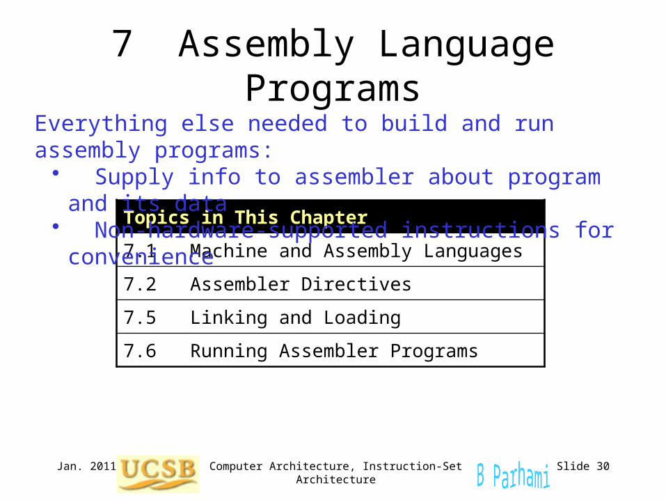
7 Assembly Language Programs
Topics in This Chapter
7.1 Machine and Assembly Languages
7.2 Assembler Directives
7.5 Linking and Loading
7.6 Running Assembler Programs
Everything else needed to build and run assembly programs:• Supply info to assembler about program and its data• Non-hardware-supported instructions for convenience
Jan. 2011 Computer Architecture, Instruction-Set Architecture Slide 31
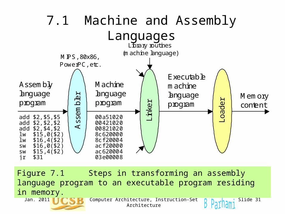
7.1 Machine and Assembly Languages
Figure 7.1 Steps in transforming an assembly language program to an executable program residing in memory.
Lin
ker
Lo
ad
er
Ass
em
ble
r
add $2,$5,$5 add $2,$2,$2 add $2,$4,$2 lw $15,0($2) lw $16,4($2) sw $16,0($2) sw $15,4($2) jr $31
00a51020 00421020 00821020 8c620000 8cf20004 acf20000 ac620004 03e00008
Assembly language program
Machine language program
Executable machine language program
Memory content
Library routines (machine language)
MIPS, 80x86, PowerPC, etc.
Jan. 2011 Computer Architecture, Instruction-Set Architecture Slide 32
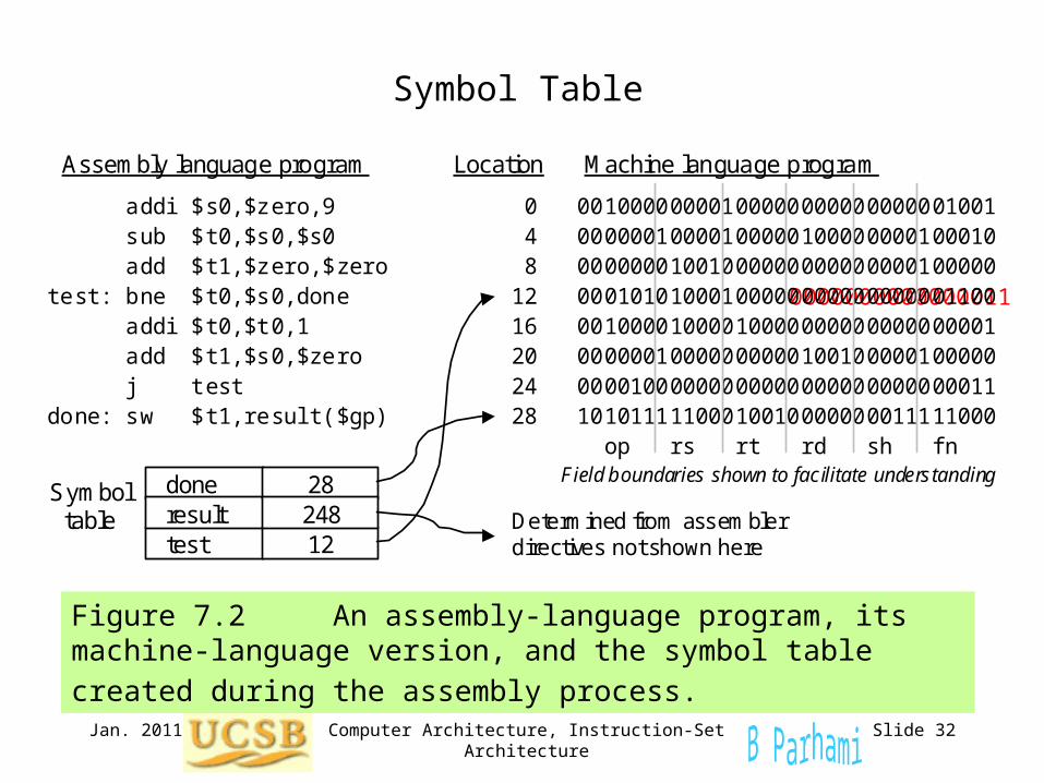
Symbol Table
Figure 7.2 An assembly-language program, its machine-language
version, and the symbol table created during the assembly process.
0 00100000000100000000000000001001
addi $s0,$zero,9
test
done result
12
28 248
4 00000010000100000100000000100010 8 00000001001000000000000000100000 12 00010101000100000000000000001100 16 00100001000010000000000000000001 20 00000010000000000100100000100000 24 00001000000000000000000000000011 28 10101111100010010000000011111000
Determined from assembler directives not shown here
Symbol table
done: sw $t1,result($gp)
sub $t0,$s0,$s0 add $t1,$zero,$zero test: bne $t0,$s0,done addi $t0,$t0,1 add $t1,$s0,$zero j test
Assembly language program Machine language program Location
op rs rt rd sh fn Field boundaries shown to facilitate understanding
0000000000000011
Jan. 2011 Computer Architecture, Instruction-Set Architecture Slide 33
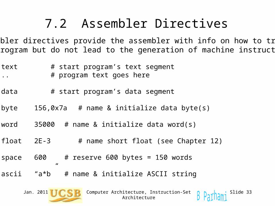
7.2 Assembler Directives Assembler directives provide the assembler with info on how to translate the program but do not lead to the generation of machine instructions .text # start program’s text segment ... # program text goes here
.data # start program’s data segment
tiny: .byte 156,0x7a # name & initialize data byte(s)
max: .word 35000 # name & initialize data word(s)
small: .float 2E-3 # name short float (see Chapter 12)
array: .space 600 # reserve 600 bytes = 150 words
str1: .ascii “a*b” # name & initialize ASCII string
Jan. 2011 Computer Architecture, Instruction-Set Architecture Slide 34
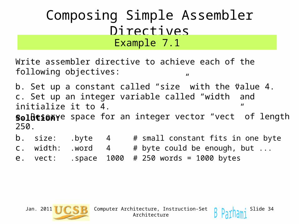
Composing Simple Assembler Directives
Write assembler directive to achieve each of the following objectives:
b. Set up a constant called “size” with the value 4.c. Set up an integer variable called “width” and initialize it to 4.e. Reserve space for an integer vector “vect” of length 250.
Example 7.1
Solution:
b. size: .byte 4 # small constant fits in one bytec. width: .word 4 # byte could be enough, but ...e. vect: .space 1000 # 250 words = 1000 bytes
Jan. 2011 Computer Architecture, Instruction-Set Architecture Slide 35
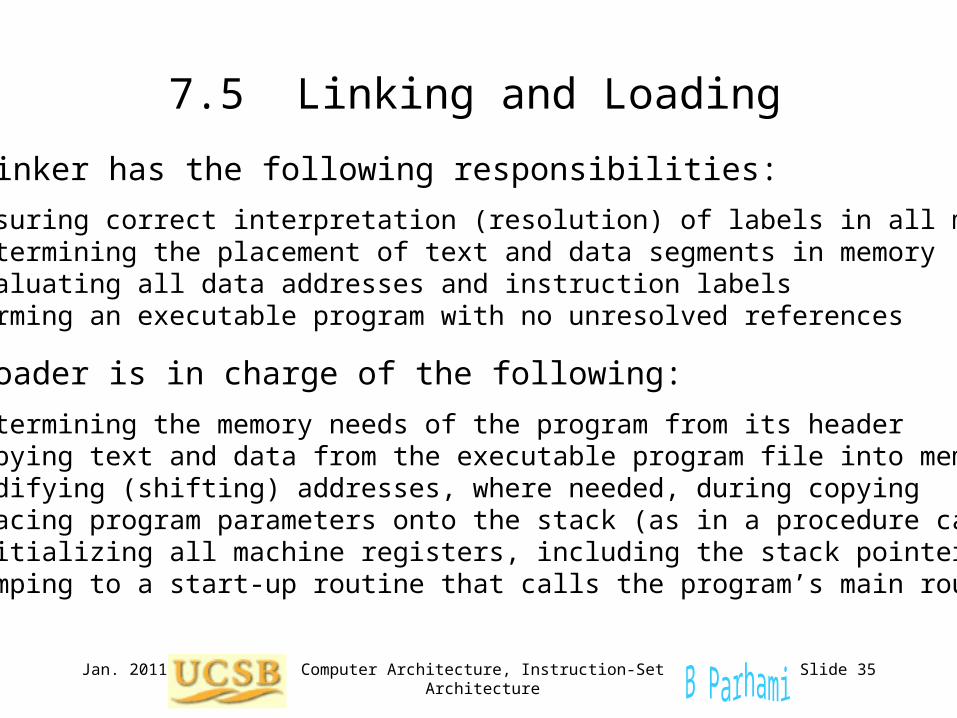
7.5 Linking and Loading
The linker has the following responsibilities:
Ensuring correct interpretation (resolution) of labels in all modules Determining the placement of text and data segments in memory Evaluating all data addresses and instruction labels Forming an executable program with no unresolved references
The loader is in charge of the following:
Determining the memory needs of the program from its header Copying text and data from the executable program file into memory Modifying (shifting) addresses, where needed, during copying Placing program parameters onto the stack (as in a procedure call) Initializing all machine registers, including the stack pointer Jumping to a start-up routine that calls the program’s main routine
Jan. 2011 Computer Architecture, Instruction-Set Architecture Slide 36
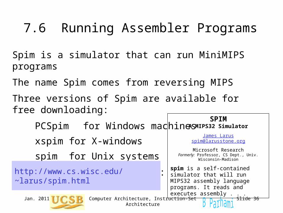
7.6 Running Assembler Programs
Spim is a simulator that can run MiniMIPS programs
The name Spim comes from reversing MIPS
Three versions of Spim are available for free downloading:
PCSpim for Windows machines
xspim for X-windows
spim for Unix systems
You can download SPIM from:
http://www.cs.wisc.edu/~larus/spim.html
SPIMA MIPS32 Simulator
James [email protected]
Microsoft ResearchFormerly: Professor, CS Dept., Univ. Wisconsin-Madison
spim is a self-contained simulator that will run MIPS32 assembly language programs. It reads and executes assembly . . .
Jan. 2011 Computer Architecture, Instruction-Set Architecture Slide 37
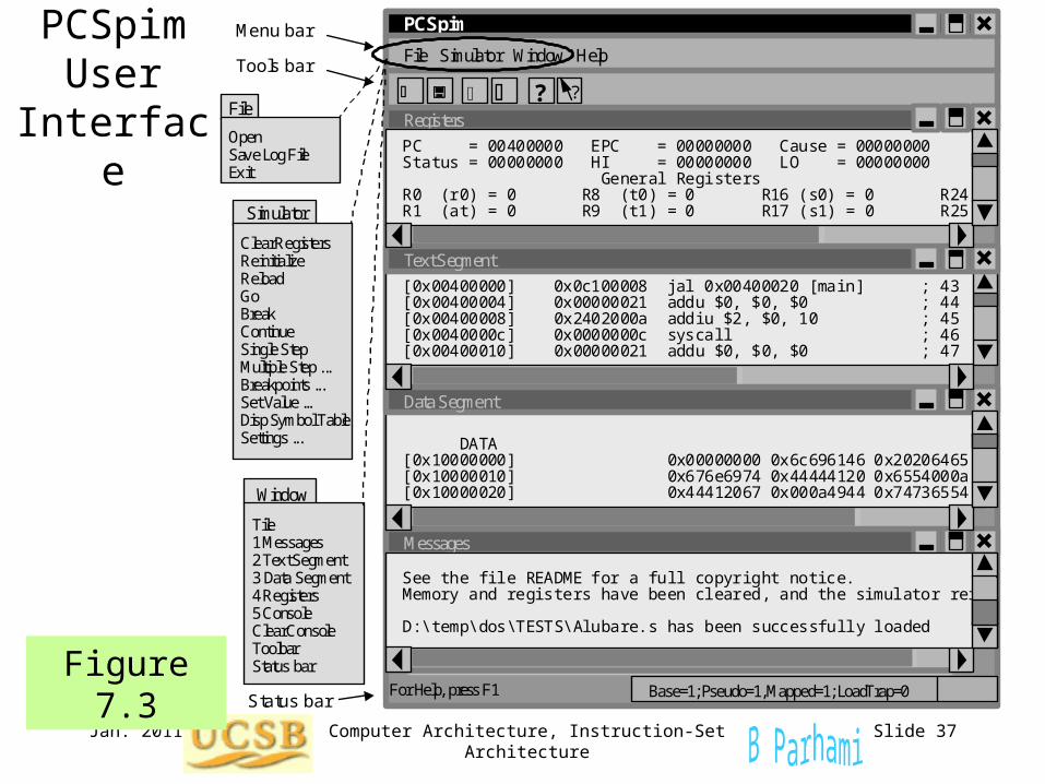
Figure 7.3
PCSpim User
Interface
Status bar
Menu bar Tools bar
File
Simulator
Window
Open Sav e Log File Ex it
Tile 1 Messages 2 Tex t Segment 3 Data Segment 4 Registers 5 Console Clear Console Toolbar Status bar
Clear Registers Reinitialize Reload Go Break Continue Single Step Multiple Step ... Breakpoints ... Set Value ... Disp Symbol Table Settings ...
For Help, press F1
PCSpim
Registers
File Simulator Window Help
PC = 00400000 EPC = 00000000 Cause = 00000000 Status = 00000000 HI = 00000000 LO = 00000000 General Registers R0 (r0) = 0 R8 (t0) = 0 R16 (s0) = 0 R24 R1 (at) = 0 R9 (t1) = 0 R17 (s1) = 0 R25
[0x00400000] 0x0c100008 jal 0x00400020 [main] ; 43 [0x00400004] 0x00000021 addu $0, $0, $0 ; 44 [0x00400008] 0x2402000a addiu $2, $0, 10 ; 45 [0x0040000c] 0x0000000c syscall ; 46 [0x00400010] 0x00000021 addu $0, $0, $0 ; 47
DATA [0x10000000] 0x00000000 0x6c696146 0x20206465 [0x10000010] 0x676e6974 0x44444120 0x6554000a [0x10000020] 0x44412067 0x000a4944 0x74736554
Text Segment
Data Segment
Messages
Base=1; Pseudo=1, Mapped=1; LoadTrap=0
?
?
See the file README for a full copyright notice. Memory and registers have been cleared, and the simulator rei D:\temp\dos\TESTS\Alubare.s has been successfully loaded
Jan. 2011 Computer Architecture, Instruction-Set Architecture Slide 38
8 Instruction Set Variations
Topics in This Chapter
8.1 Complex Instructions
8.2 Alternative Addressing Modes
8.3 Variations in Instruction Formats
8.4 Instruction Set Design and Evolution
8.5 The RISC/CISC Dichotomy
The MiniMIPS instruction set is only one example• How instruction sets may differ from that of MiniMIPS• RISC and CISC instruction set design philosophies
Jan. 2011 Computer Architecture, Instruction-Set Architecture Slide 39
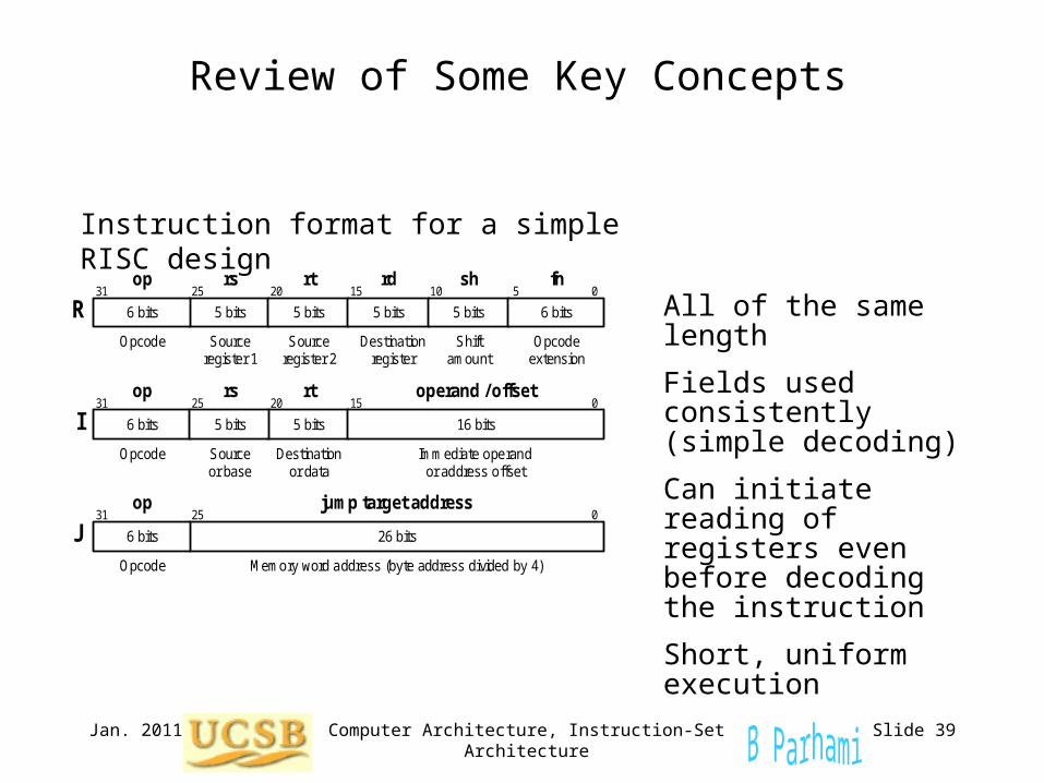
Review of Some Key Concepts
All of the same length
Fields used consistently (simple decoding)
Can initiate reading of registers even before decoding the instruction
Short, uniform execution
Instruction format for a simple RISC design
5 bits 5 bits
31 25 20 15 0
Opcode Source register 1
Source register 2
op rs rt
R 6 bits 5 bits
rd
5 bits
sh
6 bits
10 5 fn
Destination register
Shift amount
Opcode extension
Immediate operand or address offset
31 25 20 15 0
Opcode Destination or data
Source or base
op rs rt operand / offset
I 5 bits 6 bits 16 bits 5 bits
0 0 0 0 0 0 0 0 0 0 0 1 1 1 1 1 1 0 0 0 0 0 0 0 0 0
31 0
Opcode
op jump target address
J Memory word address (byte address divided by 4)
26 bits
25
6 bits
Computer Architecture, Instruction-Set ArchitectureJan. 2011 Slide 40
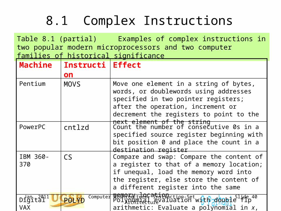
8.1 Complex InstructionsTable 8.1 (partial) Examples of complex instructions in two popular modern microprocessors and two computer families of historical significance
Machine Instruction Effect
Pentium MOVS Move one element in a string of bytes, words, or doublewords using addresses specified in two pointer registers; after the operation, increment or decrement the registers to point to the next element of the string
PowerPC cntlzd Count the number of consecutive 0s in a specified source register beginning with bit position 0 and place the count in a destination register
IBM 360-370 CS Compare and swap: Compare the content of a register to that of a memory location; if unequal, load the memory word into the register, else store the content of a different register into the same memory location
Digital VAX POLYD Polynomial evaluation with double flp arithmetic: Evaluate a polynomial in x, with very high precision in intermediate results, using a coefficient table whose location in memory is given within the instruction
Jan. 2011 Computer Architecture, Instruction-Set Architecture Slide 41
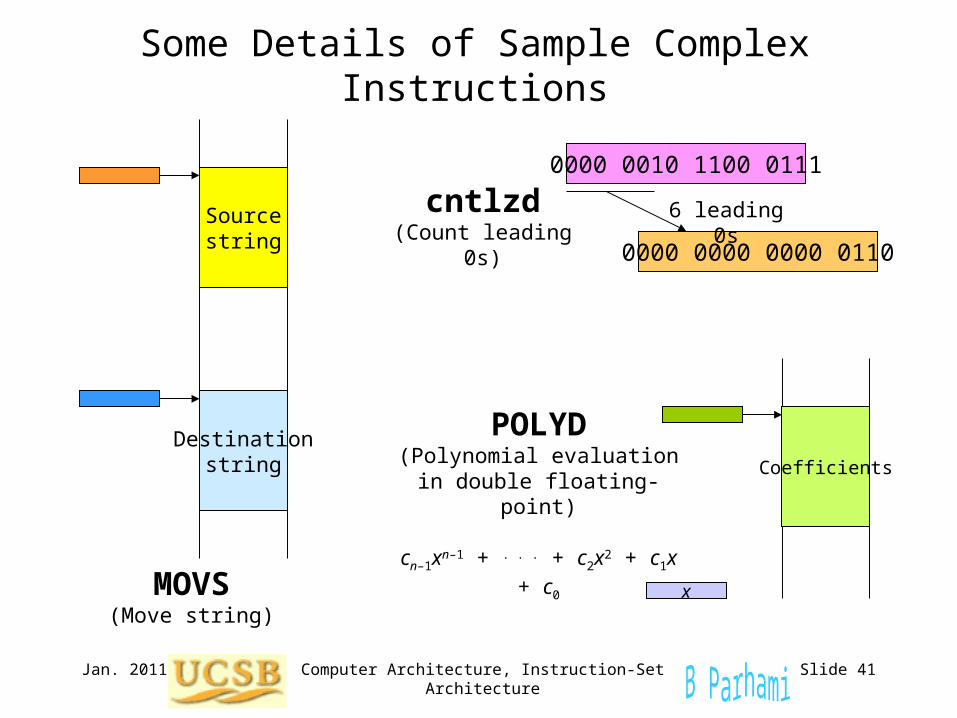
Some Details of Sample Complex Instructions
MOVS(Move string)
Sourcestring
Destinationstring
cntlzd(Count leading 0s)
0000 0010 1100 0111
0000 0000 0000 0110
6 leading 0s
POLYD(Polynomial evaluation in
double floating-point)
cn–1xn–1 + . . . + c2x2 + c1x + c0
Coefficients
x
Jan. 2011 Computer Architecture, Instruction-Set Architecture Slide 42
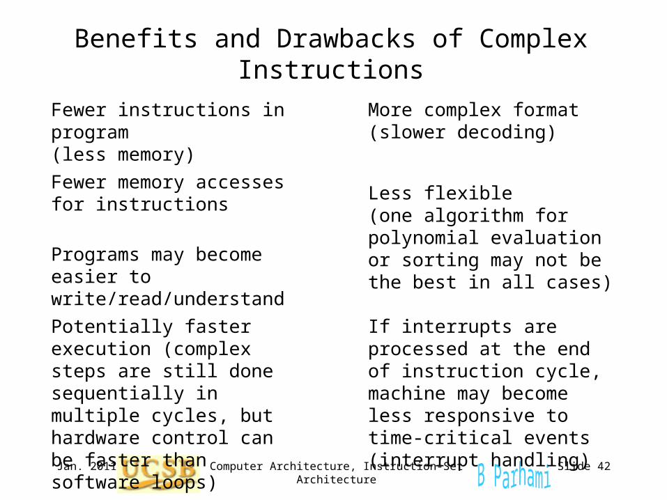
Benefits and Drawbacks of Complex Instructions
Fewer instructions in program(less memory)
Potentially faster execution (complex steps are still done sequentially in multiple cycles, but hardware control can be faster than software loops)
Fewer memory accesses for instructions
Programs may become easier to write/read/understand
More complex format(slower decoding)
Less flexible (one algorithm for polynomial evaluation or sorting may not be the best in all cases)
If interrupts are processed at the end of instruction cycle, machine may become less responsive to time-critical events (interrupt handling)
Jan. 2011 Computer Architecture, Instruction-Set Architecture Slide 43
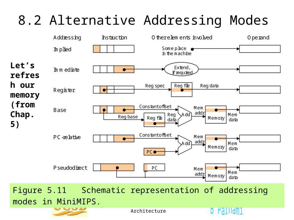
8.2 Alternative Addressing Modes
Figure 5.11 Schematic representation of addressing modes in MiniMIPS.
Addressing Instruction Other elements involved Operand
Implied
Immediate
Register
Base
PC-relative
Pseudodirect
Some place in the machine
Extend, if required
Reg file Reg spec Reg data
Memory Add
Reg file
Mem addr
Constant offset
Reg base Reg data
Mem data
Add
PC
Constant offset
Memory
Mem addr Mem
data
Memory Mem data
PC Mem addr
Let’s refresh our memory (from Chap. 5)
Jan. 2011 Computer Architecture, Instruction-Set Architecture Slide 44
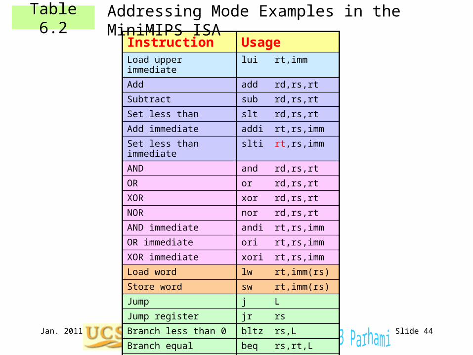
Table 6.2Instruction UsageLoad upper immediate lui rt,imm
Add add rd,rs,rt
Subtract sub rd,rs,rt
Set less than slt rd,rs,rt
Add immediate addi rt,rs,imm
Set less than immediate slti rt,rs,imm
AND and rd,rs,rt
OR or rd,rs,rt
XOR xor rd,rs,rt
NOR nor rd,rs,rt
AND immediate andi rt,rs,imm
OR immediate ori rt,rs,imm
XOR immediate xori rt,rs,imm
Load word lw rt,imm(rs)
Store word sw rt,imm(rs)
Jump j L
Jump register jr rs
Branch less than 0 bltz rs,L
Branch equal beq rs,rt,L
Branch not equal bne rs,rt,L
Addressing Mode Examples in the MiniMIPS ISA
Jan. 2011 Computer Architecture, Instruction-Set Architecture Slide 45
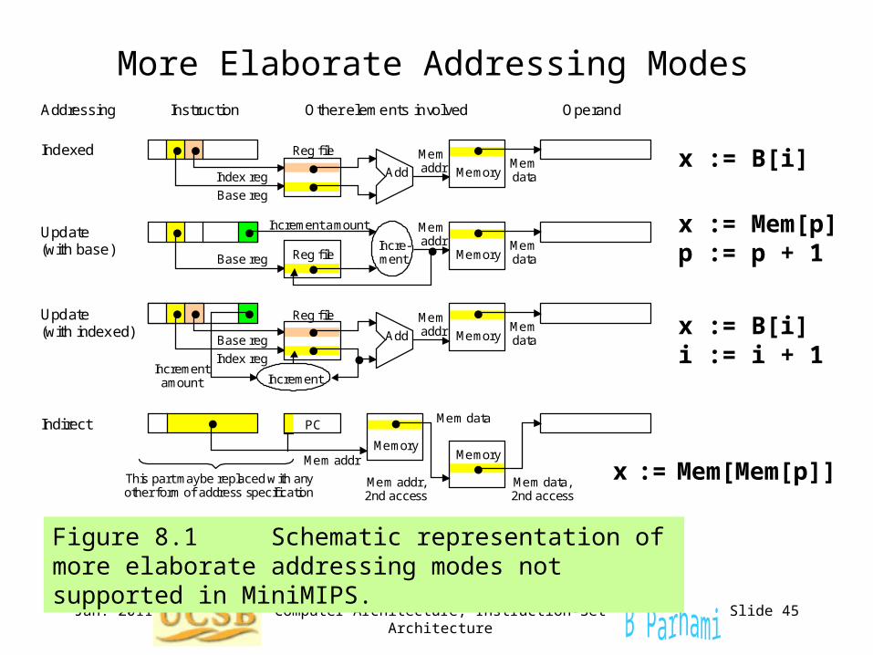
More Elaborate Addressing Modes
Figure 8.1 Schematic representation of more elaborate addressing modes not supported in MiniMIPS.
Addressing Instruction Other elements involved Operand
Mem data PC
Mem addr Memory
Memory Add
Reg file Mem addr Mem
data Index reg
Base reg
Memory Reg file
Mem addr Mem
data
Increment amount
Base reg
Indirect
Indexed
Update (with base)
Update (with indexed) Memory Add
Reg file Mem addr Mem
data
Index reg
Base reg
Increment amount
Memory
Mem addr, 2nd access
Mem data, 2nd access
This part maybe replaced with any other form of address specif ication
Incre-ment
Increment
x := B[i]
x := Mem[p]p := p + 1
x := B[i]i := i + 1
x := Mem[Mem[p]]
Jan. 2011 Computer Architecture, Instruction-Set Architecture Slide 46
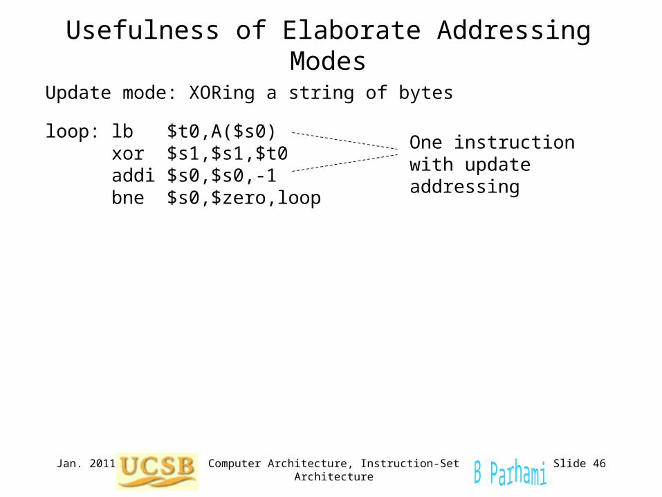
Usefulness of Elaborate Addressing Modes
Update mode: XORing a string of bytes
loop: lb $t0,A($s0) xor $s1,$s1,$t0 addi $s0,$s0,-1 bne $s0,$zero,loop
One instruction with update addressing
Jan. 2011 Computer Architecture, Instruction-Set Architecture Slide 47
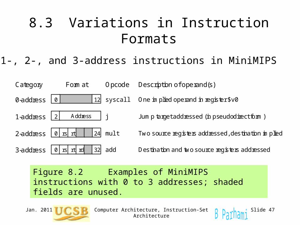
8.3 Variations in Instruction Formats
Figure 8.2 Examples of MiniMIPS instructions with 0 to 3 addresses; shaded fields are unused.
3-address
0-address
1-address
2-address
syscall
j
mult
add
One implied operand in register $v0
Destination and two source registers addressed
Two source registers addressed, destination implied
Jump target addressed (in pseudodirect form)
Category Format Opcode Description of operand(s)
Address 2
12
rt rs 0 24
rt rs 0 rd 32
0
0-, 1-, 2-, and 3-address instructions in MiniMIPS
Jan. 2011 Computer Architecture, Instruction-Set Architecture Slide 48
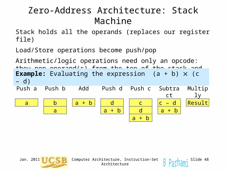
Zero-Address Architecture: Stack Machine
Stack holds all the operands (replaces our register file)
Load/Store operations become push/pop
Arithmetic/logic operations need only an opcode: they pop operand(s) from the top of the stack and push the result onto the stack
Example: Evaluating the expression (a + b) (c – d)
a
Push a
ab
Push b
a + b
Add
d
Push d
a + b d
Push c
a + b
c c – d
Subtract
a + bResult
Multiply
Jan. 2011 Computer Architecture, Instruction-Set Architecture Slide 49
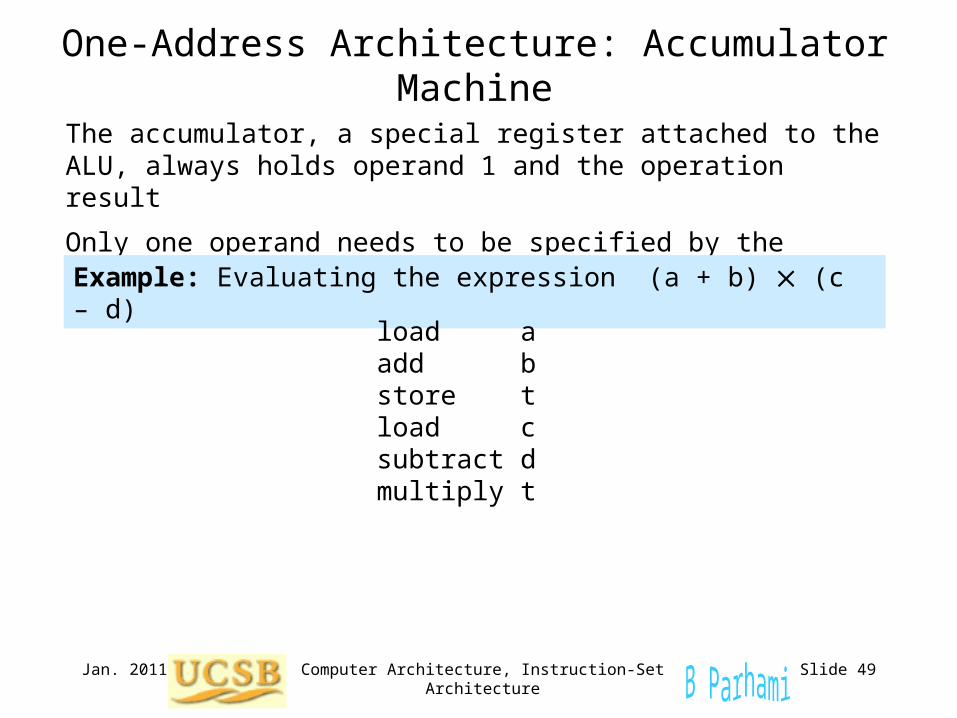
One-Address Architecture: Accumulator Machine
The accumulator, a special register attached to the ALU, always holds operand 1 and the operation result
Only one operand needs to be specified by the instruction
Example: Evaluating the expression (a + b) (c – d)
load aadd bstore tload csubtract dmultiply t
Jan. 2011 Computer Architecture, Instruction-Set Architecture Slide 50
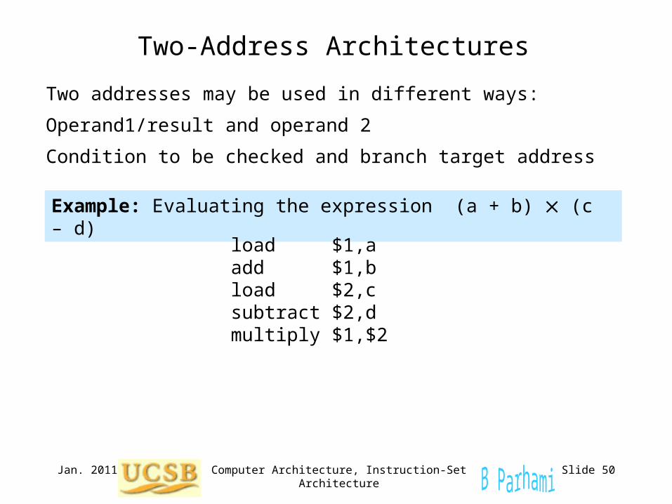
Two-Address Architectures
Two addresses may be used in different ways:
Operand1/result and operand 2
Condition to be checked and branch target address
Example: Evaluating the expression (a + b) (c – d)
load $1,aadd $1,bload $2,csubtract $2,dmultiply $1,$2
Jan. 2011 Computer Architecture, Instruction-Set Architecture Slide 51
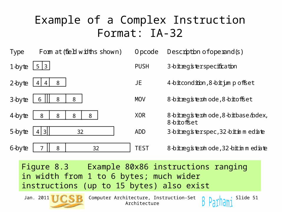
Figure 8.3 Example 80x86 instructions ranging in width from 1 to 6 bytes; much wider instructions (up to 15 bytes) also exist
Example of a Complex Instruction Format: IA-32
4-byte
1-byte
2-byte
3-byte
6-byte
5-byte
Type Format (field widths shown) Opcode Description of operand(s)
8 8 6
PUSH
JE
MOV
XOR
3-bit register specification
8-bit register/mode, 8-bit base/index, 8-bit offset
8-bit register/mode, 8-bit offset
4-bit condition, 8-bit jump offset
ADD
TEST 8-bit register/mode, 32-bit immediate
3-bit register spec, 32-bit immediate
5 3
4 4 8
3 32 4
7 8 32
8 8 8 8
Jan. 2011 Computer Architecture, Instruction-Set Architecture Slide 52
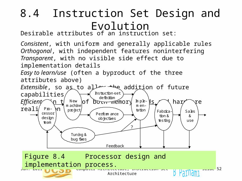
8.4 Instruction Set Design and Evolution
Figure 8.4 Processor design and implementation process.
Pro- cessor design team
New machine project
Tuning & bug fixes
Performance objectives
Instruction-set definition
Imple- men- tation Fabrica-
tion & testing
Sales &
use
?
Feedback
Desirable attributes of an instruction set:
Consistent, with uniform and generally applicable rulesOrthogonal, with independent features noninterferingTransparent, with no visible side effect due to implementation detailsEasy to learn/use (often a byproduct of the three attributes above)Extensible, so as to allow the addition of future capabilitiesEfficient, in terms of both memory needs and hardware realization
Jan. 2011 Computer Architecture, Instruction-Set Architecture Slide 53
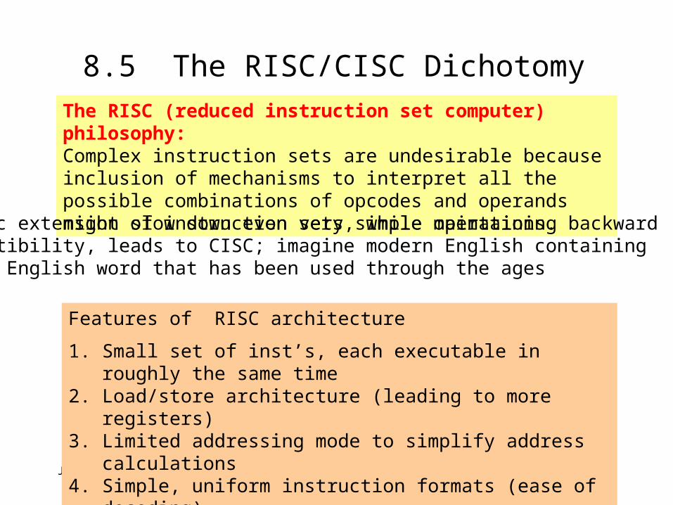
8.5 The RISC/CISC DichotomyThe RISC (reduced instruction set computer) philosophy: Complex instruction sets are undesirable because inclusion of mechanisms to interpret all the possible combinations of opcodes and operands might slow down even very simple operations.
Features of RISC architecture
1. Small set of inst’s, each executable in roughly the same time2. Load/store architecture (leading to more registers)3. Limited addressing mode to simplify address calculations4. Simple, uniform instruction formats (ease of decoding)
Ad hoc extension of instruction sets, while maintaining backward compatibility, leads to CISC; imagine modern English containingevery English word that has been used through the ages
Jan. 2011 Computer Architecture, Instruction-Set Architecture Slide 54
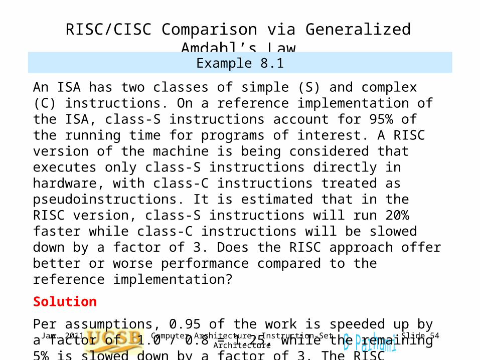
RISC/CISC Comparison via Generalized Amdahl’s Law
Example 8.1
An ISA has two classes of simple (S) and complex (C) instructions. On a reference implementation of the ISA, class-S instructions account for 95% of the running time for programs of interest. A RISC version of the machine is being considered that executes only class-S instructions directly in hardware, with class-C instructions treated as pseudoinstructions. It is estimated that in the RISC version, class-S instructions will run 20% faster while class-C instructions will be slowed down by a factor of 3. Does the RISC approach offer better or worse performance compared to the reference implementation?
Solution
Per assumptions, 0.95 of the work is speeded up by a factor of 1.0 / 0.8 = 1.25, while the remaining 5% is slowed down by a factor of 3. The RISC speedup is 1 / [0.95 / 1.25 + 0.05 3] = 1.1. Thus, a 10% improvement in performance can be expected in the RISC version.
Jan. 2011 Computer Architecture, Instruction-Set Architecture Slide 55
Some Hidden Benefits of RISC
In Example 8.1, we established that a speedup factor of 1.1 can be expected from the RISC version of a hypothetical machine
This is not the entire story, however!
If the speedup of 1.1 came with some additional cost, then one might legitimately wonder whether it is worth the expense and design effort
The RISC version of the architecture also:
Reduces the effort and team size for design
Shortens the testing and debugging phase
Simplifies documentation and maintenance
Cheaper product and shorter time-to-market