Embed Size (px)
Citation preview

A-220
Balls roll in four rows of a precisely-ground raceway onan LM rail and an LM block. The end plate attached tothe LM block causes the trains of balls to circulate.The raceways are cut into deep grooves that have aradius closer to that of the balls than in theconventional design, using special equipment and an
extremely advanced cutting technique. This designprovides high vibration and impact resistance, and thehigh damping capacity required for machine tools,making types NR and NRS capable of bearing ultra-heavy loads greater than those that can be borne bythe roller type.
Japanese Patent Nos. 2649743
LM Guide NR and NRS — Ultra-Heavy-Load, High-Rigidity Type
Fig. 1 Construction of Model NR•NRS
LM block
End plate
End seal
LM rail
Greasenipple
Ball
Construction and Features
Side seal
Inner seal
Type NR — radial type
Oil valve
Type NRS — four-way equal-load type
Cross Section
Improved damping capacityWhen cutting is not being performed, the LM blockmoves as smoothly and lively as normal. Duringcutting, the block receives a cutting load and thecontact area between the balls and the racewayexpands, producing appropriate roll-and-slide motionwhere both rolling and sliding occur. This increasesfrictional resistance, resulting in increased dampingability.
Since the absolute amount of sliding is slight, verylittle wear results and the service life is not affected.
Highly rational LM GuideThe excessive differential sliding seen with the Gothic-arch groove does not occur with the LM Guide. Themotion during fast feeding is smooth, and thepositioning accuracy remains high. During cutting,
however, appropriate differential sliding occurs inproportion to the cutting load, resulting in increasedrolling resistance and damping capacity, and improvedcutting performance. Types NR and NRS are thushighly rational linear-motion guides.
High rigidityIf an LM block and rail are not sufficiently rigid, thesystem itself will lack rigidity in the reverse-radial andlateral directions. To increase the rigidity of LMblocks and rails, we have created the optimum designwithin the given dimensions, taking advantage of theFEM technique.
For radial-type NR and four-way equal-load-type NRS,we offer two different models with the samedimensions but different characteristics. Select themodel best suited for your specifications.
www.thk.ru BERG AB [email protected] Тел. (495)-727-22-72, ф. (495)-223-3071

Ultra-heavy loadThe radius of the raceways is approximately the sameas the ball radius. This makes it possible for the ballcontact area to be made equal to or greater than theroller contact area, thus ensuring a load-bearingcapacity superior to that of the roller type.
This raceway design is free from the various problemsseen with the roller type, including locking due to
skewed rollers; the inability to ensure smooth motionas a result of the application of a preload to increaserigidity, giving rise to the extraordinary fluctuations inresistance that occur as rollers enter a loaded area; anddeterioration of the load-bearing capacity due touneven contact between rollers due to accuracy errorsin the mounting surface. While maintaining the ease ofuse of other types of LM Guides, types NR and NRSare also capable of withstanding heavy loads.
A-221
A-IV
Types and Features
Types NR and NRS-RCompact type
Types NR and NRS-ATapped-hole flange type
Types NR and NRS-BThrough-hole flange type
For heavy loads
The LM blocks of types NR and NRS-Rhave the smallest width of any modelsin this series, and are provided withtapped holes. Useful where space forthe table is limited.
The flange of the LM block is providedwith tapped holes to allow simpleassembly, making it suitable for use inbuild-up systems.
The flange of the LM block is providedwith through holes, making it usefulwhere the table cannot be drilled formounting-bolt through holes.
For ultra-heavy loads
Types NR and NRS-LRCompact type
Types NR and NRS-LATapped-hole flange type
Types NR and NRS-LBThrough-hole flange type
While they have the same cross-sectional shapes as types NR and NRS-R, these ultra-heavy-load types areprovided with extra load-bearing ballsto increase theirload rating.
While they have the same cross-sectional shapes as types NR and NRS-A, these ultra-heavy-load types areprovided with extra load-bearing ballsto increase their load rating.
While they have the same cross-sectional shapes as types NR and NRS-B, these ultra-heavy-load types areprovided with extra load-bearing ballsto increase their load rating.
www.thk.ru BERG AB [email protected] Тел. (495)-727-22-72, ф. (495)-223-3071

Rigidity Up 200% Against Main LoadsThe 90° contact design adopted in type NR results in adifference in rigidity from the 45° contact design.Under radial load P, deflection in the radial direction is44% less with type NR than with 45° contact types.
The relationship between radial load and deflection isillustrated below. As shown, where rigidity in theradial direction is a requirement, type NR isadvantageous over 45° contact types.
Rigidity Up 200% Against Lateral andReverse-Radial LoadsSince the distance H from the LM rail bottom surfaceto the bottom groove balls (which are subjected tolateral loads) is short in LM Guide NR, the ratio of LM-rail width W to H is small. In addition the distance Tfrom the LM-rail mounting-bolt seat to the rail bottomsurface is short. Thus, under lateral loads, the LM railundergoes only a limited amount of deflection,enabling the rail to maintain high rigidity against suchloads.
Moreover, now that length B has been decreased andthickness A has been increased, the strength of the LMblock can be increased against the reverse-radial andlateral loads that act to open the block. Thus, the 90°contact design improves rigidity against reverse-radialloads.
Compared with conventional equivalent modelsmanufactured by THK, the balls are smaller and thenumber of effective balls is approximately 1.3 timesgreater, thereby increasing static rigidity.
A-222
Characteristics of Types NR and NRS
Fig. 2 Deflection under Radial Load
Def
lect
ion
in th
e ra
dial
dire
ctio
n
Deflec
tion
Def
lect
ion
Deflection in theradial direction
Contact angle: 90° Contact angle: 45°
Fig. 3 Deflection under Radial Load (clearance: normal; preload: none)
Contact angle: 45°
Contact angle: 90°
Applied load (kN)
Def
lect
ion
Load and deflection (Da = 6.35 mm) for different contact angles
(Deffection for 24 balls)
Radial contact design
Fig. 4 Cross Section
www.thk.ru BERG AB [email protected] Тел. (495)-727-22-72, ф. (495)-223-3071

Comparison of Contact Surface and InternalStress among Different Contact DesignsThe dimensions of the contact area and the magnitudeof the internal stress of a ball vary greatly dependingon the shape of the contact surface. The actual contactsurface, will not be as large as it appears, because the
retainer holds the roller, reducing its effective length.In addition, mounting errors may influence the stressdistribution around the contact area, significantlyaffecting the amount of differential slip.
A-223
A-IV
Fig. 5 Comparison of Contact Surfaces (ball: ø6.350; roller: ø6 x 6l)
Contact stressdistribution 1
Normal-clearancecontact surface
Contact surface underpreload
Change in the contactsurface due to mountingerrors
Contact stressdistribution 2
Change in theamount of
differential sliding:None
≤ ≈ <
Change in theamount of
differential sliding:None
Change in theamount of
differential sliding:Significant
Change in theamount of
differential sliding:Significant
www.thk.ru BERG AB [email protected] Тел. (495)-727-22-72, ф. (495)-223-3071

A-224
Load Rating and Permissible Moment in Various Directions
Load rating
Fig. 6
Radial direction
Lateraldirections
Reverse-radial direction
Types NR and NRS can bear loads in all four directions:radial, reverse-radial, and the two lateral directions.
The basic load ratings of types NR and NRS are in theradial direction indicated in Fig. 6. The values arepresented in the corresponding dimension tables.Values in the reverse-radial and lateral directions canbe obtained from Table 1.
The basic load ratings of type NRS in four directions(radial, reverse-radial, and the two lateral directions)are equivalent to one another. The values arepresented in the corresponding dimension table.
Equivalent loadAn equivalent load for type NR when reverse-radial andlateral loads are exerted on its LM blocksimultaneously can be obtained using the followingequation:
PE = X•PL + Y•PT
wherePE : equivalent load (N)
- In the reverse-radial direction- In the lateral directions
PL : reverse-radial load (N)PT : lateral load (N)X and Y : equivalent factor (see Table 2)
Lateraldirections
PE X Y
1
0.5
2
1
Table 2 Type NR Equivalent Factor
Equivalent load in the reverse-radial direction
Equivalent load in the lateral directions
C
CL=0.78C
CT=0.48C
CO
COL=0.71CO
COT=0.45CO
Table 1 Type NR Basic Load Ratings in Various Directions
Radial direction
Reverse-radial directionLateral
directions
Direction Basic dynamic-load rating Basic static-load rating
An equivalent load for type NRS when reverse-radialand lateral loads are exerted on its LM blocksimultaneously can be obtained using the followingequation:
PE = PR (PL ) + PT
wherePE : equivalent load (N)
- In the radial direction- In the reverse-radial direction- In the lateral directions
PR : radial load (N)PL : reverse-radial load (N)PT : lateral load (N)
www.thk.ru BERG AB [email protected] Тел. (495)-727-22-72, ф. (495)-223-3071

A-225
A-IV
Permissible momentIn types NR and NRS, a single LM block can bearmoments in all directions. Table 3 and Table 4 presentthe permissible moments in directions MA, MB, and MC
for a single LM block and double LM blocks laid overone another (no data for direction MC).
0.49
0.88
0.96
1.7
1.4
2.4
2.6
4.4
4.2
6.8
6.8
12.5
11.2
18.8
15.7
25.8
24.9
38.3
2.9
4.7
5.1
8.3
7.4
12.1
13.8
22.0
21.7
34.1
34.9
62.5
57.0
92.8
79.5
124
132
184
0.31
0.55
0.61
1.1
0.85
1.5
1.7
2.8
2.6
4.3
4.3
7.9
7.1
11.9
9.9
16.3
15.8
24.3
1.8
3.0
3.3
5.2
4.7
7.6
8.8
13.9
13.8
21.6
22.1
39.7
36.2
58.9
50.4
78.9
83.6
117
0.58
0.79
1.1
1.5
1.7
2.3
3.3
4.4
5.2
6.8
8.7
11.9
14.4
18.9
20.0
25.9
32.5
40.7
Unit : kNm
NR 25X
NR 25XL
NR 30
NR 30L
NR 35
NR 35L
NR 45
NR 45L
NR 55
NR 55L
NR 65
NR 65L
NR 75
NR 75L
NR 85
NR 85L
NR100
NR100L
Table 3 Type-NR Static Permissible Moment
MA MB MC
Single block
Single block
Single block
Doubleblock
DoubleblockModel No.
Direction
0.49
0.88
0.96
1.7
1.4
2.4
2.6
4.4
4.2
6.8
6.8
12.5
11.2
18.8
15.7
25.8
24.9
38.3
2.9
4.7
5.1
8.3
7.4
12.1
13.8
22.0
21.7
34.1
34.9
62.5
57.0
92.8
79.5
124
132
184
0.49
0.88
0.96
1.7
1.4
2.4
2.6
4.4
4.2
6.8
6.8
12.5
11.2
18.8
15.7
25.8
24.9
38.3
2.9
4.7
5.1
8.3
7.4
12.1
13.8
22.0
21.7
34.1
34.9
62.5
57.0
92.8
79.5
124
132
184
0.58
0.79
1.1
1.5
1.7
2.3
3.3
4.4
5.2
6.8
8.7
11.9
14.4
18.9
20.0
25.9
32.5
40.7
NRS 25X
NRS 25XL
NRS 30
NRS 30L
NRS 35
NRS 35L
NRS 45
NRS 45L
NRS 55
NRS 55L
NRS 65
NRS 65L
NRS 75
NRS 75L
NRS 85
NRS 85L
NRS100
NRS100L
Unit : kNm
Table 4 Type-NRS Static Permissible Moment
MA MB MC
Single block
Single block
Single block
Doubleblock
DoubleblockModel No.
Direction
Fig. 7
www.thk.ru BERG AB [email protected] Тел. (495)-727-22-72, ф. (495)-223-3071

A-226
Accuracy Standards
The accuracy of types NR and NRS are divided into fivegrades, normal, high, precision, super-precision, andultra-precision, in accordance with the model numbersshown in Table 5.
Fig. 8
Fig. 9 Relationship Between LM-Rail Length and Running Parallelism
Normal grade
LM-Rail length (mm)
www.thk.ru BERG AB [email protected] Тел. (495)-727-22-72, ф. (495)-223-3071

A-227
A-IV
NR/NRS 65
NR/NRS 75
NR/NRS 85
NR/NRS100
NR/NRS25X
NR/NRS 30
NR/NRS 35
NR/NRS 45
NR/NRS 55
±0.07
0.02
±0.07
0.025
H
±0.04
0.015
±0.04
0.015
±0.05
0.015
±0.05
0.02
±0.1
0.03
±0.1
0.03
±0.1
0.02
±0.1
0.03
±0.1
0.03
±0.1
0.03
0.01
0.015
0-0.07
0-0.07
0.007
0.007
0 -0.04
0-0.04
0.007
0.01
0-0.05
0-0.05
0.007
0.010
0-0.05
0-0.05
0.005
0.005
0-0.02
0-0.02
0.005
0.007
0-0.03
0-0.03
0.005
0.007
0-0.03
0-0.03
0.003
0.003
0-0.01
0-0.01
0.003
0.005
0-0.02
0-0.02
P SP UPModel No.
Accuracy standard HighNormal Precision Super-precision
Ultra-precision
No symbol
Tolerance for height M
Tolerance for the height M difference among LM blocks
Tolerance for rail-to-block lateral distance W2
Tolerance for rail-to-block lateral distance W2 difference among LM blocks
Running parallelism of LM-block surface C with respect to surface A
Item
Running parallelism of LM-block surface D with respect to surface B
D (as per Fig. 9)
C (as per Fig. 9)
Unit : mm
Table 5 Accuracy Standard
Tolerance for height M
Tolerance for the height M difference among LM blocks
Tolerance for rail-to-block lateral distance W2
Tolerance for rail-to-block lateral distance W2 difference among LM blocks
Running parallelism of LM-block surface C with respect to surface A
Running parallelism of LM-block surface D with respect to surface B
C (as per Fig. 9)
D (as per Fig. 9)
Running parallelism of LM-block surface D with respect to surface B
Running parallelism of LM-block surface C with respect to surface A
Tolerance for rail-to-block lateral distance W2 difference among LM blocks
Tolerance for rail-to-block lateral distance W2
Tolerance for height M
Tolerance for the height M difference among LM blocks
D (as per Fig. 9)
C (as per Fig. 9)
www.thk.ru BERG AB [email protected] Тел. (495)-727-22-72, ф. (495)-223-3071

A-228
Radial clearance
Table 6 presents the radial clearances of types NR andNRS.
NR/NRS 25X
NR/NRS 30
NR/NRS 35
NR/NRS 45
NR/NRS 55
NR/NRS 65
NR/NRS 75
NR/NRS 85
NR/NRS100
- 3 ~ +2
- 4 ~ +2
- 4 ~ +2
- 5 ~ +3
- 6 ~ +3
- 8 ~ +3
-10 ~ +4
-13 ~ +4
-14 ~ +4
- 6 ~ -3
- 8 ~ -4
- 8 ~ -4
-10 ~ -5
-11 ~ -6
-14 ~ -8
-17 ~ -10
-20 ~ -13
-24 ~ -14
-9 ~ - 6
- 12 ~ - 8
- 12 ~ - 8
- 15 ~ -10
- 16 ~ - 11
- 20 ~ - 14
- 24 ~ - 17
- 27 ~ - 20
- 34 ~ - 24
Unit : µm
Table 6 Type NR/NRS Radial Clearances
Model No.
Clearance symbol
C1
NormalUnder a light
preload
No symbol
C0
Medium preload
Fig. 10
Model-number coding
NR45 LR 2 SS C0 + 1200L P Z - II
No. of axes installed on the same plane (see Note)
Provision of a plate cover
Accuracy grade
LM-rail material (in mm)
No. of LM blocks combined on a single axis
Classification of the LM block
Model No.
Radial clearance
Provision of end, side, and inner seals
(for a model with end seals, the symbol is UU; see page A-203)
Note: This coding is based on the assumption of one set of code for a one-axis unit. (A configuration of two axes installed in parallel is given at least two sets of code.)
Radial clearance
www.thk.ru BERG AB [email protected] Тел. (495)-727-22-72, ф. (495)-223-3071

Side sealPrevents contaminants from entering an LM blockfrom below.
Inner sealInstalled in a LM block.
LaCS (laminated contact scraper)Unlike metal scrapers, the LaCS surface-contacts theLM rail and is capable of removing foreign objects.The LaCS is provided as an option that is highlycontamination-protective against minute foreignobjects that have been difficult to remove withconventional metal scrapers.
A-229
A-IV
Contamination Protection
Types NR and NRS are provided with end and sideseals as standard contamination-protection accessories.
End sealStandard accessory
Double sealUse two end seals to enhance the contamination-protection capacity.
ScraperRemoves spatters and similar large foreign matter.
Fig. 11
End seal
Phillips-headtapping screw
Fig. 12
Phillips-headtapping screw
End sealSpacer
End seal
Phillips-headtapping screw
End sealSpacer
Side seal
Fig. 14
Fig. 13
Inner seal
Fig. 15
LaCS
Fig. 16
www.thk.ru BERG AB [email protected] Тел. (495)-727-22-72, ф. (495)-223-3071

NR/NRS 25XA/XRNR/NRS 25XLA/XLR
NR/NRS 30A/RNR/NRS 30LA/LR
NR/NRS 35A/RNR/NRS 35LA/LR
NR/NRS 45A/RNR/NRS 45LLA/LR
NR/NRS 55A/RNR/NRS 55LA/LR
NR/NRS 65A/RNR/NRS 65LA/LR
NR/NRS 75A/RNR/NRS 75LA/LR
NR/NRS 85A/RNR/NRS 85LA/LR
NR/NRS 100A/RNR/NRS 100LA/LR
81.8100.8
97.1119.6108.5134138170160.6198.1183.4243.4214.6270.6247.4303.4287.4327.4
83102
98120.5109.5135139171163200.5186246218274248.5304.5294334
83102
98120.5109.5135139171163200.5186246218274248.5304.5294334
90.4109.4107129.5119.7145.2149.2181.2173210.5196.6256.6229285264.4320.4311.2351.2
89.2108.2104.4126.9117.1142.6147.4179.4171.4208.9194.2254.2226.6282.6260.2316.2304.4344.4
96.8115.8113.4135.9127.3152.8157.6189.6181.6219.1204.8264.8237.6293.6273.8329.8321.6361.6
106.5125.5124.5147138.5164172204198.5236225285
114.5133.5133.5156148.5174182.5214.5208.5246235.5295.5
Table 7 Type NR/NRS: LM Block Overall Length with a contamination-protection Accessory Attached Unit : mm
KKHHModel. No. No symbol UU SS DD ZZ KK ZZHH
Ο
Ο
Ο
Ο
Ο
Ο
Ο
Ο
Ο
Ο
Ο
Ο
Ο
Ο
Ο
Ο
Ο
Ο
Ο
Ο
Ο
Ο
Ο
Ο
Ο
Ο
Ο
Ο
Ο
Ο
Ο
Ο
Ο
Ο
Ο
Ο
Ο
Ο
Ο
Ο
Ο
Ο
Ο
Ο
Ο
Ο
Ο
Ο
Ο
Ο
Ο
Ο
Ο
Ο
Ο
Ο
Ο
Ο
Ο
Ο
×
×
×
Ο
Ο
Ο
Ο
Ο
Ο
×
×
×
Note: Ο = Applicable
× = Not Applicable
Seal resistance valueFor the maximum value of seal resistance of sealstypes NR and NRS...UU per LM block in which greaseis applied see Table 8.
NR/NRS 25X
NR/NRS 30
NR/NRS 35
NR/NRS 45
NR/NRS 55
NR/NRS 65
NR/NRS 75
NR/NRS 85
NR/NRS 100
15
17
23
24
29
42
42
42
51
Seal resistance value
Table 8 Maximum Resistance Value of Seals to Types NR/NRS
Unit : N
Model No.
Steel tape type SP (patent pending)A special steel tape is available for types NR and NRS.With machine tools, contamination protectionmeasures are essential. This steel tape, consisting ofultra-thin-sheet stainless steel (SUS304), covers therail-mounting holes and thereby reinforces thesealability of the seal in use. This prevents the entry ofcoolant and chips from above the rails, which could notbe prevented by the conventional means. (An endpiece of type EP is used to install the steel tape.)
Steel tape type SP
End piece type EP
Fig. 17
Contamination-protection-accessorysymbolWhere a contamination-protection accessory isrequired, specify the corresponding symbol shownbelow.
Attaching a contamination-protection accessory to anLM block changes the block overall length dependingon the block type (see Table 7).
UU
SS
ZZ
DD
KK
ZZHH
KKHH
Contamination-protection accessory Symbol
End seal (on both end faces)
End seal + side seal + inner seal + scraper
Double seal + side seal + inner seal + scraper
Double seal + side seal + inner seal
End seals + side seal + inner seal+ metal scraper + LaCSDouble seal + side seal + inner seal+ metal scraper + LaCS
End seal + side seal + inner seal
A-230
www.thk.ru BERG AB [email protected] Тел. (495)-727-22-72, ф. (495)-223-3071

A-231
A-IV
Mounting proceduresFasten using adhesive tape and the end pieces.
1. Using a special removal jig (page A-163), remove theLM block from the LM rail.
2. Completely remove grease and oil from the LM-railtop surface, to which the steel tape is adhered.Clean the surface well. Use a highly volatile agent(e.g., industrial alcohol) to remove grease and oil.
3. While gradually peeling off the steel-tape backing,adhere it to the surface while keeping it taut andstraight.
4. Rub the tape against the rail surface until it attainsclose contact. Although the bonding strength isincreased as time elapses, the tape can be peeledfrom the rail by pulling it upward.
5. Insert an LM block into the LM rail.
6. Attach end pieces to both ends of the LM rail, andsecurely attach the steel tape to the rail. Fasten theset screws on the top side only. A tapped hole isprovided on each end piece for the attachment of abellows.
Fig. 18
Fig. 19
Fig. 20
Fig. 21
Fig. 22
LM block
Specialremoval jig
Mounting surface(hatched)
Steel tapeBacking
Steel tapeDo not form intoan acute angle
LM block
Specialremoval jig
Steel tape: Type SP
Set screw
End piece: Type EP
Bellows-mounting tapped hole
Notes: 1. The set screws at both ends are provided to lightly hold folded-over steel-tape ends in place. Stoptightening a set screw when you feel it reach the rail surface. Be sure not to overtighten it.
2. The steel tape is made of thin sheet steel. Mishandling of the tape may result in an injury such as a cuton the hand. Therefore, when handling a steel tape, wear rubber gloves or the like to ensure safety.
www.thk.ru BERG AB [email protected] Тел. (495)-727-22-72, ф. (495)-223-3071
A-232
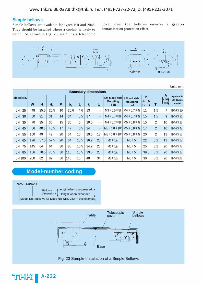
Simple bellowsSimple bellows are available for types NR and NRS.They should be installed where a coolant is likely toenter. As shown in Fig. 23, installing a telescopic
cover over the bellows ensures a greatercontamination-protection effect.
( )JN 25
JN 30
JN 35
JN 45
JN 55
JN 65
JN 75
JN 85
JN 100
b
48
60
70
86
100
126
145
156
200
W
25.5
31
35
40.5
49
57.5
64
70.5
82
H
25.5
31
35
40.5
49
57.5
64
70.5
82
H1
10
14
15
17
20
20
30
30
30
P
26.6
34
36
47
54
64
80
110
140
4.6
5.5
6
6.5
10
13.5
10.5
15.5
15
b1
13
17
20.5
24
29.5
36.2
34.2
39.5
40
t1
-
-
-
-
18
20
26
28
34
t2 t3
11
15
15
17
20
22
25
39.5
30
A,LAB,LB T
7
9
10
10
13
13
20
20
20
LmaxLmin
A
M4 × 0.7 × 4l
M4 × 0.7 × 4l
M5 × 0.8 × 4l
M5 × 0.8 × 4l
M5 × 0.8 × 4l
M6 × 5l
M6 × 5l
M6 × 5l
M6 × 5l
M3 × 0.5 × 5l
M4 × 0.7 × 8l
M4 × 0.7 × 8l
M5 × 0.8 × 10l
M5 × 0.8 × 10l
M6 × 12l
M6 × 12l
M6 × 12l
M8 × 16l
NR/NRS 25X
NR/NRS 30
NR/NRS 35
NR/NRS 45
NR/NRS 55
NR/NRS 65
NR/NRS 75
NR/NRS 85
NR/NRS100
1.5
1.5
2
2
2
3.2
3.2
3.2
3.2
Model No.
Unit : mm
Applicable
LM-Guide
model
LM rail side Mounting
bolt
Boundary dimensions
LM block sideMounting
bolt
Model-number coding
JN25 - 60/420
Model No. (bellows for types NR-NRS 25X in this example)
Bellows dimensions
length when compressed
length when expanded( )
Fig. 23 Sample Installation of a Simple Bellows
TableTelescopiccover
Simplebellows
Base
www.thk.ru BERG AB [email protected] Тел. (495)-727-22-72, ф. (495)-223-3071

A-233
A-IV
Precautions on Use
Mounting-Surface Height and CornerProfileNormally, mounting surfaces for LM blocks and railshave lateral reference sections to aid in positioning andassembly of the rails and blocks with a high degree ofaccuracy.
For the reference-section shoulder height, see Table 9.
Provide enough space for the corner profile of amounting surface so that the corner does not interferewith chamfers made on the LM blocks and rails, orprovide the corner with a radius smaller than cornerradius r specified in Table 9.
Fig. 24
NR/NRS25X
NR/NRS30
NR/NRS35
NR/NRS45
NR/NRS55
NR/NRS65
NR/NRS75
NR/NRS85
NR/NRS100
0.5
1.0
1.0
1.0
1.5
1.5
1.5
1.5
2.0
5
5
6
8
10
10
12
14
16
5
5
6
8
10
10
12
14
16
5.5
7
9
11.5
14
15
15
17
20
E
Unit : mm
Table 9 Mounting-Surface Shoulder Height and Corner Radius
Model No.Corner radius r (max.)
LM-rail shoulder
heightH1
LM-block shoulder
max. heightH2
Special removal jigIn types NR and NRS, when the LM block is removedfrom the LM rail, the balls may fall off and cause anaccident. Therefore, to remove the LM block from theLM rail, always use the special removal jig.
Fig. 25
LM block
Specialremoval jig
End piece type EPIn types NR and NRS, when an LM block is removedfrom an LM rail, the balls may fall off and cause anaccident. Therefore, these types are delivered withend pieces installed, in order to prevent the LM blocksfrom detaching.
If the LM Guide is used without the end pieces, besure the LM block is not allowed to overrun.
The end piece can be used to fasten a steel tape inplace and is applicable to LM rails types SSR, SR, andHSR.
Fig. 26 End Piece Type EP for Types NR and NRS
26
31
38
49
57
69.4
81.7
91.4
106.4
NR/NRS 25X
NR/NRS 30
NR/NRS 35
NR/NRS 45
NR/NRS 55
NR/NRS 65
NR/NRS 75
NR/NRS 85
NR/NRS 100X
14
14
16
18
20
22
28
22
25
25
31
32.5
41
46.5
59
56
68
73
A B C
1.5
1.5
2
2
2
3.2
3.2
3.2
3.2
T
Unit : mm
Table 10 Dimensions of NR and NRS End Piece Type EP
Model . No.
www.thk.ru BERG AB [email protected] Тел. (495)-727-22-72, ф. (495)-223-3071

A-234
Lubrication adaptorFor types NR and NRS, lubrication adaptorsspecifically for oil lubrication are available.
Even in wall-hung, inverted, and other installations inwhich oil lubrication is difficult, the adaptor provideslubricant feed to all four rows of a raceway at a givenrate.
FeaturesAs a result of the incorporation of a constant-ratedistributor, the lubrication adaptor specifically fortypes NR and NRS can reliably feed a given amount oflubricant to all raceways.
It is economical to feed the optimum amount oflubricant at all times, thus eliminating waste.
For piping, simply connect an intermittent lubricationpump (the type used for general machine tools and thelike) to the feed holes (M8) provided on the adaptorfront and side panels.
Fig. 27 Construction
Lubricationplate
Lubricationplate
To the lubricationpump
To the lubricationpump
Constant-ratedistributor
Specifications
32 to 64 cSt recommended
0.03 x 4 or 0.06 x 4 cc/shot
Ø4 or Ø6
Aluminum alloy
Viscosity range of the lubricant used
Discharge rate
Connected pipe diameter
Material
Fig. 28
A30N
A35N
A45N
A55N
A65N
A85N
Model No.
cc/shotM × l M1 × l1
Width
W
56
66
81
94
119
147
Height
M
29
33
38
45.5
55.5
68.5
T
25
25
25
25
25
25
W1
29
35
48
56
67
92
M1
14.5
17
20
22
26.3
34
B
46
54
67
76
92
114
E
14
16.5
16.5
20.5
25.5
32
N
5.3
6
7
7
11.5
15.5
T1
5.3
5.3
7.8
7.8
7.8
7.8
d
3.5
4.5
6.6
6.6
9
9
M8 × 8
M8 × 8
M8 × 8
M8 × 8
M8 × 8
M8 × 8
M8 × 8
M8 × 8
M8 × 8
M8 × 8
M8 × 8
M8 × 8
0.03 × 4
0.06 × 4
Unit : mmTable 11 Dimensions of the Lubrication Adaptor
drill through
www.thk.ru BERG AB [email protected] Тел. (495)-727-22-72, ф. (495)-223-3071

A-235
A-IV
LM-Rail Standard and Maximum Lengths
Table 12 presents the standard and maximum lengthsof LM rails for types NR and NRS. If your maximumlength is not within the range of this table, we offerspecial LM rails intended for connected use.
For dimension G when a special length is specified, werecommend those listed in Table 10. A large
dimension G tends to reduce stability at the rail ends,which may degrade accuracy.
For connected use, we offer LM rails that ensure theelimination of level differences at joints. Therefore,when placing an order, please specify the overalllength of the LM rails you require.
230270350390470510590630710750830950990
107011101190123013101350143014701550159017101830195020702190231024302470
NR/NRS25X
40
15
3000
280360440520600680760840920
10001080116012401320140014801560164017201800188019602040220023602520268028403000
NR/NRS30
80
20
3000
280360440520600680760840920
10001080116012401320140014801560164017201800188019602040220023602520268028403000
NR/NRS35
80
20
3000
570675780885990
10951200130514101515162017251830193520402145225023552460256526702775288029853090
NR/NRS45
105
22.5
3000
780900
102011401260138015001620174018601980210022202340246025802700282029403060
120
30
3000
NR/NRS55
1270157020202620
150
35
3000
NR/NRS65
1280158020302630
150
40
3000
NR/NRS75
1530189022502610
180
45
3000
NR/NRS85
1340176021802600
210
40
3000
NR/NRS100
Unit : mm
Table 12 Type NR and type NRS LM-Rail Standard and Maximum Lengths
Model No.
LM-rail
standard
length
(L0)
Standard pitch F
Max. length
G
Notes :• The maximum length varies by accuracy grade. For questions regarding the maximum length, pleasecontact us.
• If connected use is impossible but a rail longer than the maximum length specified in the table isrequired, please contact us.
www.thk.ru BERG AB [email protected] Тел. (495)-727-22-72, ф. (495)-223-3071

A-236
NR•NRS-R Type (Heavy-load type)NR•NRS-LR Type (Ultra-heavy-load type) Compact type
NR/NRS 25XRNR/NRS 25XLR
NR/NRS 30RNR/NRS 30LR
NR/NRS 35RNR/NRS 35LR
NR/NRS 45RNR/NRS 45LR
NR/NRS 55RNR/NRS 55LR
NR/NRS 65RNR/NRS 65LR
NR/NRS 75RNR/NRS 75LR
NR/NRS 85RNR/NRS 85LR
NR/NRS 100RNR/NRS 100LR
62.481.6
70.993.4
77.9103.4
105137
123.6160.8
143.6203.6
170.2226.2
194.9251
223.4263.4
3525
4030
5036
6040
7547.5
7055
8065
8070
150100
83102
98120.5
109.5135
139171
163200.5
186246
218274
248.5304.5
294334
L1
10
10
12
15
18
22
26
28
35
T
25.5
31
35
40.5
49
60
68
73
85
K
7
7
8
10
11
16
18
20
23
NC
32
40
50
60
65
76
95
100
130
BLength
L
50
60
70
86
100
126
145
156
200
Width
W
31
38
44
52
63
75
83
90
105
Height
M
M6 × 8
M8 × 10
M8 × 12
M10 × 17
M12 × 18
M16 × 20
M18 × 25
M18 × 25
M18 × 27
S × l
Model No.
External dimensions LM-block dimensions
Notes:• For permissible static moments MA, MB, and MC, see page A-255.• For standard LM-rail lengths, see page A-235.• For model-number coding, see page A-228.
(E)1)
www.thk.ru BERG AB [email protected] Тел. (495)-727-22-72, ф. (495)-223-3071

A-237
A-IV
33.044.0
48.764.9
63.185.7
96.0126
131170
189260
271355
336435
479599
84.6113
122162
155210
231303
310402
436600
610800
751972
10401300
25.934.5
38.251.0
49.567.2
75.398.8
103133
148204
212278
264342
376470
59.879.7
86.1115
109148
163214
220284
309425
431566
531687
737920
0.430.55
0.741.0
1.11.4
2.02.8
3.34.3
6.08.7
8.711.6
12.315.8
21.826.1
C0kN
CkN
C0kN
CkN
40
80
80
105
120
150
150
180
210
17
21
24.5
29
36.5
43
44
48
57
Pitch
F
12.5
16
18
20.5
23.5
31.5
35
35.5
50
W2
Height
M1
25
28
34
45
53
63
75
85
100
WidthW10
-0.05
B-M6F
B-M6F
B-M6F
B-PT1/8
B-PT1/8
B-PT1/8
B-PT1/8
B-PT1/8
B-PT1/4
3.9
3.9
5.2
5.2
5.2
8.2
8.2
8.2
8.2
d0
4
5
6
7
8
9
9
10
12
E1
10
9.5
9
14
13.5
13.5
13
13
10
E
7
7
8
8
10
15
17
20
23
N1
6 × 9.5 × 8.5
7 × 11 × 9
9 × 14 × 12
14 × 20 × 17
16 × 23 × 20
18 × 26 × 22
22 × 32 × 26
24 × 35 × 28
26 × 39 × 32
d × D × h
NRS TypeNR Type
3.1
4.3
6.2
9.8
14.5
20.3
24.6
30.5
42.6
Unit : mm
Grease nipple
LM block
kg
LMrail
kg/m
LM-rail dimensions Basic load rating Mass
Notes: 1)Pilot holes for side nipples are not drilled through so as to prevent the entry of foreign matter. If a side nipple hole is required, contact us.
(E)1)
www.thk.ru BERG AB [email protected] Тел. (495)-727-22-72, ф. (495)-223-3071
A-238
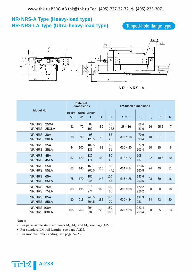
NR•NRS-A Type (Heavy-load type)NR•NRS-LA Type (Ultra-heavy-load type) Tapped-hole flange type
NR/NRS 25XA NR/NRS 25XLA
NR/NRS 30ANR/NRS 30LA
NR/NRS 35ANR/NRS 35LA
NR/NRS 45ANR/NRS 45LA
NR/NRS 55ANR/NRS 55LA
NR/NRS 65ANR/NRS 65LA
NR/NRS 75ANR/NRS 75LA
NR/NRS 85ANR/NRS 85LA
NR/NRS 100ANR/NRS 100LA
62.481.6
70.993.4
77.9103.4
105137
123.6160.8
143.6203.6
170.2226.2
194.9251
223.4263.4
4522.5
5226
6231
8040
9547.5
11055
13065
14070
150100
83102
98120.5
109.5135
139171
163200.5
186246
218274
248.5304.5
294334
L1
16
18
20
22
24
28
30
34
38
T1
25.5
31
35
40.5
49
60
68
73
85
K
7
7
8
10
11
16
18
20
23
NC
59
72
82
100
116
142
165
185
220
BLength
L
72
90
100
120
140
170
195
215
260
Width
W
31
38
44
52
63
75
83
90
105
Height
M
M8 × 16
M10 × 18
M10 × 20
M12 × 22
M14 × 24
M16 × 28
M18 × 30
M20 × 34
M20 × 38
S × l
Model No.
External dimensions LM-block dimensions
Notes:• For permissible static moments MA, MB, and MC, see page A-225.• For standard LM-rail lengths, see page A-235.• For model-number coding, see page A-228.
(E)1)
www.thk.ru BERG AB [email protected] Тел. (495)-727-22-72, ф. (495)-223-3071
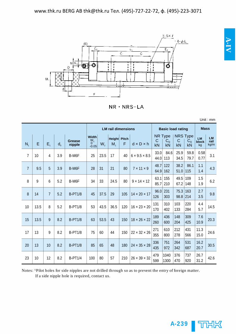
A-239
A-IV
33.044.0
48.764.9
63.185.7
96.0126
131170
189260
271355
336435
479599
84.6113
122162
155210
231303
310402
436600
610800
751972
10401300
25.934.5
38.251.0
49.567.2
75.398.8
103133
148204
212278
264342
376470
59.879.7
86.1115
109148
163214
220284
309425
431566
531687
737920
0.580.77
1.11.4
1.51.9
2.73.5
4.45.7
7.610.9
11.315.0
16.220.7
26.731.2
C0kN
CkN
C0kN
CkN
40
80
80
105
120
150
150
180
210
17
21
24.5
29
36.5
43
44
48
57
Pitch
F
23.5
31
33
37.5
43.5
53.5
60
65
80
W2
Height
M1
25
28
34
45
53
63
75
85
100
WidthW10
-0.05
B-M6F
B-M6F
B-M6F
B-PT1/8
B-PT1/8
B-PT1/8
B-PT1/8
B-PT1/8
B-PT1/4
3.9
3.9
5.2
5.2
5.2
8.2
8.2
8.2
8.2
d0
4
5
6
7
8
9
9
10
12
E1
10
9.5
9
14
13.5
13.5
13
13
10
E
7
7
8
8
10
15
17
20
23
N1
6 × 9.5 × 8.5
7 × 11 × 9
9 × 14 × 12
14 × 20 × 17
16 × 23 × 20
18 × 26 × 22
22 × 32 × 26
24 × 35 × 28
26 × 39 × 32
d × D × h
3.1
4.3
6.2
9.8
14.5
20.3
24.6
30.5
42.6
NRS TypeNR Type
Unit : mm
Grease nipple
LM block
kg
LMrail
kg/m
LM rail dimensions Basic load rating Mass
Notes: 1)Pilot holes for side nipples are not drilled through so as to prevent the entry of foreign matter. If a side nipple hole is required, contact us.
(E)1)
www.thk.ru BERG AB [email protected] Тел. (495)-727-22-72, ф. (495)-223-3071

A-240
NR•NRS-B Type (Heavy-load type)NR•NRS-LB Type (Ultra-heavy-load type) Through-hole flange type
NR/NRS 25XB NR/NRS 25XLB
NR/NRS 30BNR/NRS 30LB
NR/NRS 35BNR/NRS 35LB
NR/NRS 45BNR/NRS 45LB
NR/NRS 55BNR/NRS 55LB
NR/NRS 65BNR/NRS 65LB
NR/NRS 75BNR/NRS 75LB
NR/NRS 85BNR/NRS 85LB
NR/NRS 100BNR/NRS 100LB
4522.5
5226
6231
8040
9547.5
11055
13065
14070
150100
83102
98120.5
109.5135
139171
163200.5
186246
218274
248.5304.5
294334
T
16
18
20
22
24
28
30
34
38
12
14
16
20
22
25
26
28
32
T1
25.5
31
35
40.5
49
60
68
73
85
K
7
7
8
10
11
16
18
20
23
NC
59
72
82
100
116
142
165
185
220
B
62.481.6
70.993.4
77.9103.4
105137
123.6160.8
143.6203.6
170.2226.2
194.9251
223.4263.4
L1
7
9
9
11
14
16
18
18
20
HLength
L
72
90
100
120
140
170
195
215
260
Width
W
31
38
44
52
63
75
83
90
105
Height
M
Model No.
External dimensions LM-block dimensions
Notes:• For permissible static moments MA, MB, and MC, see page A-225.• For standard LM-rail lengths, see page A-235.• For model-number coding, see page A-228.
(E)1)
www.thk.ru BERG AB [email protected] Тел. (495)-727-22-72, ф. (495)-223-3071

A-241
A-IV
33.044.0
48.764.9
63.185.7
96.0126
131170
189260
271355
336435
479599
84.6113
122162
155210
231303
310402
436600
610800
751972
10401300
25.934.5
38.251.0
49.567.2
75.398.8
103133
148204
212278
264342
376470
59.879.7
86.1115
109148
163214
220284
309425
431566
531687
737920
0.580.77
1.11.4
1.51.9
2.73.5
4.45.7
7.610.9
11.315.0
16.220.7
26.731.2
3.1
4.3
6.2
9.8
14.5
20.3
24.6
30.5
42.6
C0kN
CkN
C0kN
CkN
40
80
80
105
120
150
150
180
210
17
21
24.5
29
36.5
43
44
48
57
Pitch
F
23.5
31
33
37.5
43.5
53.5
60
65
80
W2
Height
M1
25
28
34
45
53
63
75
85
100
WidthW10
-0.05
B-M6F
B-M6F
B-M6F
B-PT1/8
B-PT1/8
B-PT1/8
B-PT1/8
B-PT1/8
B-PT1/4
3.9
3.9
5.2
5.2
5.2
8.2
8.2
8.2
8.2
d0
4
5
6
7
8
9
9
10
12
E1
10
9.5
9
14
13.5
13.5
13
13
10
E
7
7
8
8
10
15
17
20
23
N1
6 × 9.5 × 8.5
7 × 11 × 9
9 × 14 × 12
14 × 20 × 17
16 × 23 × 20
18 × 26 × 22
22 × 32 × 26
24 × 35 × 28
26 × 39 × 32
d × D × h
NRS TypeNR Type
Unit : mm
Grease nipple
LM block
kg
LMrail
kg/m
LM-rail dimensions Basic load rating Mass
Notes: 1)Pilot holes for side nipples are not drilled through so as to prevent the entry of foreign matter. If a side nipple hole is required, contact us.
(E)1)
www.thk.ru BERG AB [email protected] Тел. (495)-727-22-72, ф. (495)-223-3071