Embed Size (px)
Citation preview
Edition: 1.0 JARUS CS-UAS Page 1 of 67
Joint Authorities for Rulemaking of Unmanned Systems
JARUS CS-UAS
Recommendations for Certification Specification for Unmanned Aircraft Systems
DOCUMENT IDENTIFIER : JARUS-DEL-WG3- CS-UAS-D.04
Edition Number : 1.0
Edition Date : 6. September 2019
Status : Final / Public Release
Intended for : Publication
Category : Recommendations
WG : 3
Intellectual Property Statement: All rights, title and interest in and to the intellectual property created, made, conceived, invented or developed by JARUS (either collectively or by members individually), shall be solely and exclusively retained by JARUS, except if JARUS voluntarily and expressly chooses to transfer it, in full or in part, to a third party. JARUS produces this material for the free use of its members, other aviation authorities and international organizations, in full or in part. Aviation authorities, who are not members of JARUS, are encouraged to become members of JARUS, at no cost, if they want to get further insight on the contents of this material. Other organizations are also welcome to use this material freely for the promotion of aviation safety, including training. All aviation authorities and other organizations using this material are encouraged to notify JARUS and provide feedback for future improvements.
Edition: 1.0 JARUS CS-UAS Page 2 of 67
DOCUMENT CHARACTERISTICS
TITLE
JARUS CS-UAS
Publications Reference: JAR_doc_16
ID Number: D-04
Document Identifier Edition Number: 1.0
JARUS DEL-WG3-CS-UAS-D.04 Edition Date: 06 September 2019
Abstract
This JARUS-CS-UAS Recommendation ultimately aims at providing recommendations for States to use for their own national legislation, concerning Certification Specification for Unmanned Aircraft Systems. The recommendations presented in this JARUS-CS-UAS Recommendation document represents the culmination of best practices and procedures used in prior UAS approvals, as well as input from JARUS-WG-3 (Airworthiness) expert members.
Keywords
Contact Person(s) Tel Unit
Markus Farner
WG-3 Leader +41 58 465 93 67
STATUS, AUDIENCE AND ACCESSIBILITY
Status Intended for Accessible via
Working Draft � General Public X Intranet □
Draft □ JARUS members � Extranet □
Proposed Issue □ Restricted □ Internet (http://jarus-rpas.org) X
Released Issue X Internal/External consultation �
Edition: 1.0 JARUS CS-UAS Page 3 of 67
DOCUMENT APPROVAL
The following table identifies the process successively approving the present issue of this document before public publication.
PROCESS NAME AND SIGNATURE WG leader DATE
WG Markus Farner 19. October 2018
Internal Consultation Markus Farner 19. October 2018
External Consultation Markus Farner 1. February 2019
Released Issue Markus Farner 6. September 2019
Edition: 1.0 JARUS CS-UAS Page 4 of 67
DOCUMENT CHANGE RECORD
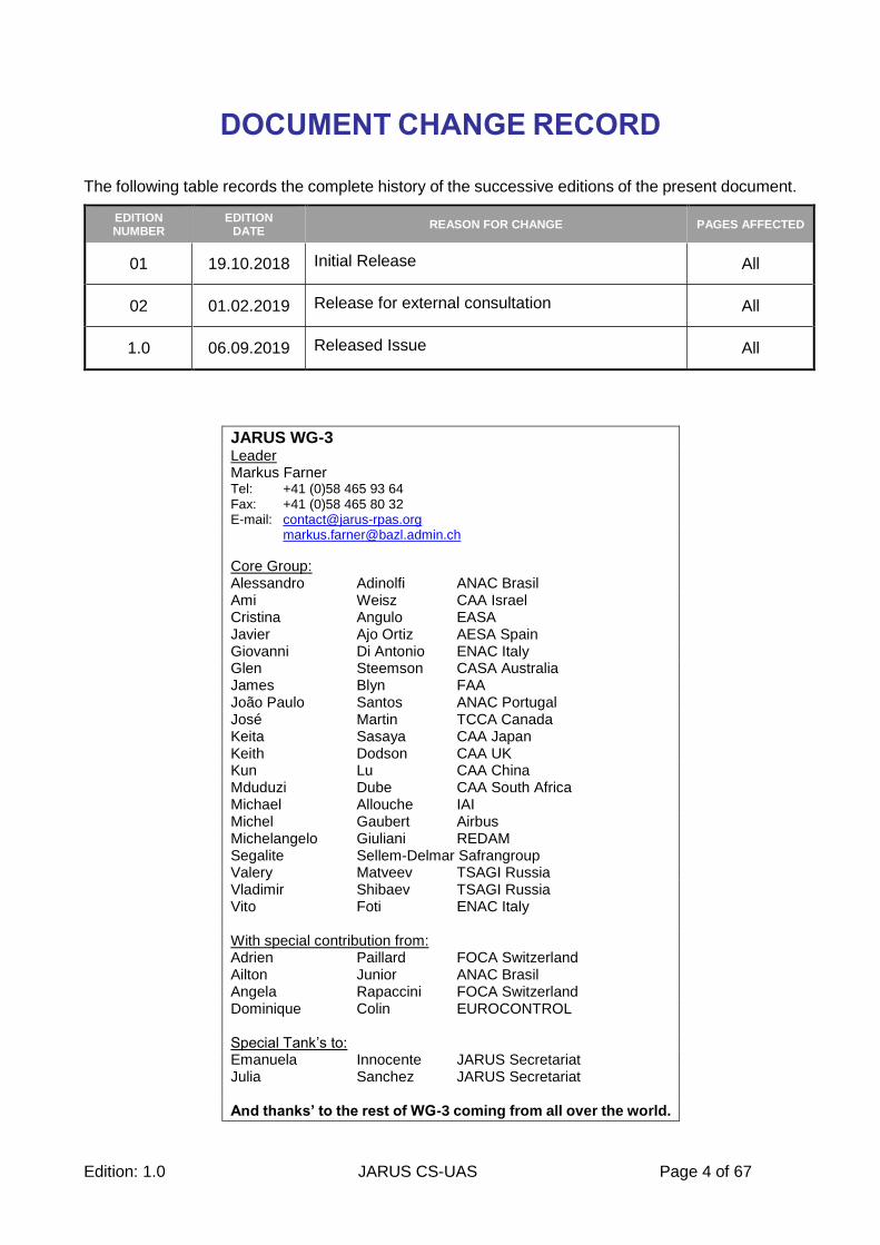
The following table records the complete history of the successive editions of the present document.
EDITION NUMBER
EDITION DATE
REASON FOR CHANGE PAGES AFFECTED
01 19.10.2018 Initial Release All
02 01.02.2019 Release for external consultation All
1.0 06.09.2019 Released Issue All
JARUS WG-3 Leader Markus Farner Tel: +41 (0)58 465 93 64 Fax: +41 (0)58 465 80 32 E-mail: [email protected] [email protected]
Core Group: Alessandro Adinolfi ANAC Brasil Ami Weisz CAA Israel Cristina Angulo EASA Javier Ajo Ortiz AESA Spain Giovanni Di Antonio ENAC Italy Glen Steemson CASA Australia James Blyn FAA João Paulo Santos ANAC Portugal José Martin TCCA Canada Keita Sasaya CAA Japan Keith Dodson CAA UK Kun Lu CAA China Mduduzi Dube CAA South Africa Michael Allouche IAI Michel Gaubert Airbus Michelangelo Giuliani REDAM Segalite Sellem-Delmar Safrangroup Valery Matveev TSAGI Russia Vladimir Shibaev TSAGI Russia Vito Foti ENAC Italy With special contribution from: Adrien Paillard FOCA Switzerland Ailton Junior ANAC Brasil Angela Rapaccini FOCA Switzerland Dominique Colin EUROCONTROL Special Tank’s to: Emanuela Innocente JARUS Secretariat Julia Sanchez JARUS Secretariat And thanks’ to the rest of WG-3 coming from all over the world.
Edition: 1.0 JARUS CS-UAS Page 5 of 67
CONTENTS
1. Introduction .......................................................................................................................... 11
1.1 Relation of CS-UAS to CS-LURS and CS-LUAS ............................................................. 11
1.2 Purpose of the document ................................................................................................ 11
1.3 Scope of the document ................................................................................................... 11
1.4 Applicability ..................................................................................................................... 12
1.5 Key concepts .................................................................................................................. 12
1.5.1 The Concept of Objective Requirements and Airworthiness Design Standards (ADS) 12
1.5.2 Basic Assumption to build the Certification Basis ..................................................... 12
1.5.3 Assumptions for non-installed required equipment such as Remote Pilot Station (RPS) and Launch and Recovery Equipment (LRE) ......................................................................... 13
1.5.4 Failure condition severity concept ............................................................................ 15
1.6 Glossary and definitions .................................................................................................. 15
1.6.1 DEFINITION OF THE GEO-FENCING FUNCTION ................................................. 15
1.6.2 Engine and Powerplant ............................................................................................ 16
1.6.3 UA-Hybrid Lift-Configuration .................................................................................... 16
1.6.4 Severity ................................................................................................................... 16
1.6.5 Ground .................................................................................................................... 16
1.6.6 Safe separation and collision avoidance .................................................................. 16
1.7 High Level Standardised Mitigations (HLSM) .................................................................. 17
1.8 Objective Requirements and Recommendations ............................................................ 17
1.9 Abbreviations or Acronyms ............................................................................................. 17
1.10 Reference material ......................................................................................................... 18
1.11 Document structure ........................................................................................................ 18
2. BOOK I Objective Requirements ........................................................................................ 19
SUBPART A – GENERAL ......................................................................................................... 19
CS-UAS.2000 Applicability ..................................................................................................... 19
CS-UAS. 2005 Approved Operating Limitations ..................................................................... 19
CS-UAS.2007 Transportation, reconfiguration and storage .................................................... 19
CS-UAS.2010 Airworthiness Design Standards (ADS) .......................................................... 19
SUBPART B – UAS OPERATION ............................................................................................. 21
CS-UAS.2100 Mass and centre of gravity .............................................................................. 21
CS-UAS.2102 Approved Flight Envelope ............................................................................... 21
CS-UAS.2105 Performance data ........................................................................................... 21
CS-UAS.2110 Minimum speeds............................................................................................. 21
CS-UAS.2115 Take-Off and minimum performance ............................................................... 22
CS-UAS.2120 Climb requirements ......................................................................................... 22
CS-UAS.2125 Rate of descent performance .......................................................................... 22
Edition: 1.0 JARUS CS-UAS Page 6 of 67
CS-UAS.2130 Landing ........................................................................................................... 22
CS-UAS.2135 Controllability and stability .............................................................................. 22
CS-UAS.2160 Vibration and buffeting .................................................................................... 23
CS-UAS.2165 Performance and flight characteristics requirements for flight in icing conditions .............................................................................................................................................. 23
SUBPART C – STRUCTURES .................................................................................................. 24
CS-UAS.2200 Structural design envelope ............................................................................. 24
CS-UAS.2205 Interaction of systems and structures .............................................................. 24
CS-UAS.2210 Structural design loads ................................................................................... 24
CS-UAS.2215 Flight load conditions ...................................................................................... 24
CS-UAS.2220 Ground and water load conditions .................................................................. 25
CS-UAS.2225 Component loading conditions ........................................................................ 25
CS-UAS.2230 Limit and ultimate loads .................................................................................. 25
CS-UAS.2235 Structural strength .......................................................................................... 25
CS-UAS.2240 Structural durability ......................................................................................... 26
CS-UAS.2245 Aeroelasticity .................................................................................................. 26
CS-UAS.2250 Design and construction principles.................................................................. 26
CS-UAS.2252 Critical Parts ................................................................................................... 27
CS UAS.2255 Protection of structure ..................................................................................... 27
CS-UAS.2260 Materials and processes ................................................................................. 27
CS-UAS.2265 Special factors of safety .................................................................................. 28
CS-UAS.2275 Cargo compartments ...................................................................................... 28
SUBPART D – DESIGN AND CONSTRUCTION ...................................................................... 29
CS-UAS.2300 UA flight control systems (mechanical systems performing pilot functions) ..... 29
CS-UAS.2305 Take-Off and Landing device systems ............................................................ 29
CS-UAS.2310 Buoyancy for UA for take-off and landing on water ......................................... 29
CS-UAS.2320 Ground Crew Protection. ................................................................................ 29
CS-UAS.2325 Fire protection ................................................................................................. 29
CS-UAS.2330 Fire protection in designated fire zones .......................................................... 30
CS-UAS.2335 Lightning protection ........................................................................................ 30
CS-UAS.2340 Design and construction information ............................................................... 30
CS-UAS.2350 Containment ................................................................................................... 30
CS-UAS.2360 Non-essential systems, equipment and installation ......................................... 31
CS -UAS.2370 External Cargo Loads .................................................................................... 31
SUBPART E – POWER PLANT INSTALLATION ...................................................................... 32
CS-UAS.2400 Powerplant installation .................................................................................... 32
CS-UAS.2405 Power or thrust control systems ...................................................................... 32
CS-UAS.2410 Powerplant installation hazard assessment .................................................... 32
CS-UAS.2415 Powerplant installation ice protection .............................................................. 33
CS-UAS.2425 Powerplant operating characteristics .............................................................. 33
Edition: 1.0 JARUS CS-UAS Page 7 of 67
CS-UAS.2430 Powerplant installation, energy storage and distribution systems .................... 33
CS-UAS.2435 Powerplant installation support systems ......................................................... 34
CS-UAS.2440 Powerplant installation fire protection .............................................................. 34
CS-UAS.2445 Powerplant installation information.................................................................. 34
SUBPART F – SYSTEMS AND EQUIPMENT ........................................................................... 36
CS-UAS 2500.UAS level system requirements ...................................................................... 36
CS-UAS 2505.General requirements on equipment installation ............................................. 36
CS-UAS 2510.Equipment, systems and installations ............................................................. 36
CS-UAS.2515 Electrical and electronic system lightning protection ....................................... 36
CS-UAS.2520 High-Intensity Radiated Fields (HIRF) Protection ............................................ 37
CS-UAS.2522 Cyber Security ................................................................................................ 37
CS-UAS.2525 UAS power supply, generation, storage, and distribution ................................ 37
CS-UAS.2529 UA Flight Control System ................................................................................ 38
CS-UAS.2530 UA External lights ........................................................................................... 38
CS-UAS.2540 Flight in icing conditions .................................................................................. 38
CS-UAS.2545 Pressurised systems elements ....................................................................... 38
CS-UAS.2550 Equipment containing high energy rotating parts ............................................ 39
CS-UAS.2555 Installation of recorders................................................................................... 39
CS-UAS.2570 Emergency Recovery Capability and Procedures (ERCP) .............................. 39
CS-UAS.2575 Command, Control and Communication Contingency ..................................... 39
SUBPART G – CREW INTERFACE AND OTHER INFORMATION .......................................... 40
CS-UAS.2600 Remote Pilot Station (Performance)................................................................ 40
CS-UAS.2605 Remote Pilot Station (Human Factors) ............................................................ 40
CS-UAS.2615 Flight, navigation, and powerplant instruments ............................................... 40
CS-UAS.2620 UAS Flight Manual .......................................................................................... 40
CS-UAS.2625 Instructions for Continued Airworthiness (ICA) ................................................ 41
SUBPART H – ANCILLARY SYSTEMS .................................................................................... 42
CS-UAS.2710 Systems for Launch and Recovery not permanently installed on the UA ........ 42
3. BOOK II Guidance Material ................................................................................................. 43
SUBPART A – GENERAL ......................................................................................................... 43
GM-UAS.1 GENERAL ........................................................................................................... 43
GM-UAS.2000 Applicability .................................................................................................... 43
GM-UAS. 2005 Approved Operating Limitations .................................................................... 43
GM-UAS.2007 Transportation, reconfiguration and storage ................................................... 44
GM-UAS.2010 Airworthiness Design Standards (ADS) .......................................................... 45
SUBPART B – UAS OPERATION ............................................................................................. 46
GM-UAS.2102 Approved Flight Envelope .............................................................................. 46
GM-UAS.2105 Performance data .......................................................................................... 46
GM-UAS.2110 Minimum speed.............................................................................................. 46
GM-UAS.2115 Take-off and minimum performance ............................................................... 47
Edition: 1.0 JARUS CS-UAS Page 8 of 67
GM-UAS.2120 Climb requirements ........................................................................................ 47
GM-UAS.2125 Rate of descent performance ......................................................................... 47
GM-UAS.2135 Controllability and stability .............................................................................. 47
GM-UAS.2160 Vibrations and buffeting ................................................................................. 48
SUBPART C – STRUCTURES .................................................................................................. 49
GM-UAS.2200 Structural design envelope ............................................................................. 49
GM-UAS.2205 Interaction of systems and structures ............................................................. 49
GM-UAS.2210 Structural design loads ................................................................................... 49
GM-UAS.2215 Flight load conditions ..................................................................................... 50
GM-UAS.2220 Ground and water load conditions .................................................................. 50
GM-UAS.2225 Component loading conditions ....................................................................... 51
GM-UAS.2240 Structural durability ........................................................................................ 51
GM-UAS.2252 Critical Parts .................................................................................................. 51
GM-UAS.2255 Protection of structure .................................................................................... 51
SUBPART D – DESIGN AND CONSTRUCTION ...................................................................... 52
GM-UAS.2305 Take-Off and Landing device systems ........................................................... 52
GM-UAS.2320 Ground Crew Protection. ................................................................................ 52
GM-UAS.2325 Fire protection ................................................................................................ 52
GM-UAS.2330 Fire protection in designated fire zones .......................................................... 52
GM-UAS.2335 Lightning protection ........................................................................................ 52
GM-UAS.2350 Containment .................................................................................................. 53
GM-UAS.2360 Non-essential systems, equipment and installation ........................................ 53
SUBPART E – POWER PLANT INSTALLATION ...................................................................... 54
GM-UAS.2400 Powerplant installation ................................................................................... 54
GM-UAS.2430 Powerplant installation, energy storage and distribution systems ................... 54
GM-UAS.2435 Powerplant installation support systems......................................................... 54
SUBPART F – SYSTEMS AND EQUIPMENT ........................................................................... 55
GM-UAS.2500 UAS level system requirements, GM-UAS 2505 General requirements on equipment installation, GM-UAS 2510 Equipment, systems and installations ........................ 55
GM-UAS.2515 Electrical and electronic system lightning protection ...................................... 55
GM-UAS.2520 High-Intensity Radiated Fields (HIRF) Protection ........................................... 55
GM-UAS.2522 Cyber Security ............................................................................................... 55
GM-UAS.2525 UAS power supply, generation, storage, and distribution ............................... 55
GM-UAS.2530 UA External lights .......................................................................................... 55
GM-UAS.2529 UA Flight Control System ............................................................................... 55
GM-UAS.2540 Flight in icing conditions ................................................................................. 56
GM-UAS.2555 Installation of recorders .................................................................................. 56
GM-UAS.2570 Emergency Recovery Capability and Procedures .......................................... 56
GM-UAS.2575 Command, Control and Communication Contingency .................................... 57
SUBPART G – CREW INTERFACE AND OTHER INFORMATION .......................................... 59

Edition: 1.0 JARUS CS-UAS Page 9 of 67
GM-UAS.2600 Remote Pilot Station (Performance) ............................................................... 59
GM-UAS.2605 Remote Pilot Station (Human Factors) ........................................................... 59
GM-UAS.2615 Flight, navigation, and powerplant instruments .............................................. 60
GM-UAS.2620 (a) UAS Flight Manual .................................................................................... 60
GM-UAS.2625 Instructions for Continued Airworthiness (ICA) ............................................... 60
SUBPART H – ANCILLARY SYSTEMS .................................................................................... 61
GM-UAS.2710 Systems for Launch and Recovery not permanently installed on the UA ........ 61
4. ANNEXES ............................................................................................................................. 62
Annex A - High Level Standardised Mitigations (HLSM) ............................................................ 62
HLSM.1 Operations are conducted over an unpopulated area ............................................... 62
HLSM.2 Operations are conducted over low population density area..................................... 62
HLSM.3 Empty Airspace (segregated) ................................................................................... 63
HLSM.4 Harmless characteristics .......................................................................................... 64
Annex B - Multiple UA’s controlled simultaneously by a single RPS and multiple RPS controlling multiple UA’s ............................................................................................................................. 65
Annex C - Non-deterministic UA ................................................................................................ 66
Annex D - Transportation of humans and livestock .................................................................... 67
Edition: 1.0 JARUS CS-UAS Page 10 of 67
EXECUTIVE SUMMARY
JARUS is a group of experts coming from National Aviation Authorities (NAAs) from the five continents, EUROCONTROL and the European Aviation Safety Agency (EASA).
Its purpose is to recommend a single set of technical, safety and operational requirements for all aspects linked to the safe operation of Unmanned Aircraft Systems (UAS). This requires review and consideration of existing regulations and other material applicable to manned aircraft, the analysis of the specific risks linked to UAS and the drafting of material to cover the unique features of UAS.
In order to provide a sound and widely supported recommendation to the interested parties, JARUS will publicly consult interested stakeholders from the UAS market, including Industry, on their draft deliverables. Since JARUS is not developing legally binding or mandatory regulatory material, this consultation is not in replacement of the usual consultation that a country uses in its rulemaking processes. The JARUS consultation is aimed at delivering a better quality, harmonised proposal for regulation. Each State or Regional Organisation will need to decide how to utilise the harmonised provisions developed by JARUS.
This CS-UAS is in line with the new spirit of the reorganisation of certification requirements into design-independent objective requirements, similar to the 2017 re-issue of FAR/CS-23. This may lead to the concept of having CS-LURS (Certification Specification for Light Unmanned Rotorcraft Systems), CS-LUAS (Certification Specification for Light Unmanned Aeroplane Systems) and other acceptable standards (that could be produced by industry bodies) as Airworthiness Design Standards (ADS) that address the differences between the aircraft-types and demonstrate compliance with CS-UAS as the objective requirements applicable to all UAS. This is seen as a logical way forward since there are already some UAS designs that do not fit into the traditional classification of either fixed-wing or rotary-wing.
These CS-UAS contain the objective requirements, supported by Guidance Material to develop the Airworthiness Design Standards. Due to the rapid evolution of UAS technology, this document will be subject to review and update when appropriate.
Edition: 1.0 JARUS CS-UAS Page 11 of 67
1. Introduction
1.1 Relation of CS-UAS to CS-LURS and CS-LUAS
The Airworthiness working group, WG3 of JARUS, began work on this document after issuing CS-LURS in October 2013 and CS-LUAS in November 2016.
Since the start of the development of CS-LUAS, the FAA and EASA initiated a rulemaking task to reorganise FAR/CS-23. Through this reorganisation of the FAR/CS-23, a new concept was introduced to provide requirements proportionate to the UAS performance and complexity and the type of operation. The certification specification is rearranged into objective requirements that are design-independent and applicable to the entire range of aeroplanes within FAR/CS-23. In addition, the requirements are supported by AMC that includes consensus standards (e.g. from ASTM) that can be considered as Airworthiness Design Standards where the design-specific details and general architecture are captured.
In the later stages of the development of CS-LUAS, the work of the group was influenced by this FAA/EASA initiative, resulting in more objective requirements in some areas.
As it was not practical to change the complete CS-LUAS in line with this new concept without incurring further delay, it was decided to issue CS-LUAS in 2016 in its current form. Although not perfect, it is considered appropriate for the majority of fixed wing UA with a MTOM of 750 kg.
The CS-UAS presented in this document is in line with the new spirit of the reorganisation of certification requirements into design-independent objective requirements.
With the new concept of Objective Requirements, supported by Airworthiness Design Standards, the existing recommendations of CS-LURS and CS-LUAS can be used as Airworthiness Design Standards to comply with the requirements in CS-UAS.
1.2 Purpose of the document
The purpose of CS-UAS is to provide recommendations for design-independent Objective Requirements as Certification Specification (CS) for Unmanned Aircraft Systems (UAS).
1.3 Scope of the document
In keeping with the JARUS concept of the three UAS categories “A or Open”, “B or Specific” and “C or Certified”, CS-UAS is intended to be used for the “Certified” category but some or all may also be used for the “Specific” category depending on the outcome of the Total Hazard and Risk Assessment.
Edition: 1.0 JARUS CS-UAS Page 12 of 67
1.4 Applicability
(a) This Certification Specification provides objective requirements for the issuance of type certificates, and changes to those certificates, for Unmanned Aircraft Systems (UAS) independent of the design of the UAS under the conditions below:
(1) MTOM not to exceed:
(i) 8618 kg / 19000 lb for UA without VTOL capability
(ii) 3175 kg / 7000 lb for UA with VTOL capability
(2) Human transportation is excluded
(3) The intended operation for which the UAS is designed is not in the open category
(4) Non-deterministic systems are excluded (e.g. artificial intelligence, machine learning)
(b) CS-UAS covers the requirements for BVLOS operation with the exception that the performance requirements for any detect and avoid technology ensuring safe separation are not yet developed
(c) CS-UAS includes requirements for the Remote Pilot Station (RPS), Launch and Recovery Equipment (LRE) and C2 Link equipment
1.5 Key concepts
1.5.1 The Concept of Objective Requirements and Airworthiness Design Standards (ADS)
Objective requirements are design-independent and applicable to the entire range of CS-UAS applicability. These objective requirements will be used as a basis to develop Airworthiness Design Standards (ADS) where the design-specific details will be captured. ADS can be developed for a TC with or without operating limitations, but in any case are used to comply with the objective requirements.
The objective requirements in Book I with the guidance material in Book ll of this CS-UAS document shall be in compliance with ICAO Annex 8 developed to include unmanned aircraft systems.
In addition, objective requirements for operational- and technical configuration and technologies not foreseen in ICAO Annex 8 at the time of issue of this CS-UAS, will be found in Annex B, C etc.
1.5.2 Basic Assumption to build the Certification Basis
o WG-3 developed CS-UAS to enable an applicant to obtain a Type Certificate (TC) for UAS
o We foresee TC’s without operating limitations (fly “wherever, whenever”) or with operating
limitations. This operating limitations are part of the type design and listed in the TCDS
o An ADS consists of a set of individual requirements and where necessary associated AMC to
comply with the objective requirements in CS-UAS
o Additional ADS (which includes the AMC) can be developed by the industry and accepted by the
authority for a TC
o CS-LUAS/LURS & AMC or any other existing aviation design standard and associated AMC can be
used for a TC containing operating limitations by applying the Total Hazard and Risk Assessment to
the operational scenario and the UAS Configuration (architecture, mass, size etc.. This results in a
Edition: 1.0 JARUS CS-UAS Page 13 of 67
subset of individual applicable requirements out of CS-LUAS/LURS & AMC or any other existing
aviation design standard for the TC
o The above concept should be applied to CS-UAS, to identify which requirements must be met by
the ADS and which operating limitations are required to provide an equivalent level of safety
o Using an existing ADS but changing the AMC will result in a new ADS
o A new ADS for a TC containing operating limitations can be developed:
- As a new set of requirements developed for a specific scenario. The Total Hazard and Risk Assessment shall be used to derive the individual applicable requirements and AMC based on the operational scenario and the UAS Configuration (architecture, mass, size etc.
- As a derivative from one or more existing ADS by applying the Total Hazard and Risk Assessment to the operational scenario and the UAS Configuration (architecture, mass, size etc.)
- An ADS can be derived from different existing aviation design standards and related AMC
1.5.3 Assumptions for non-installed required equipment such as Remote Pilot Station (RPS) and Launch and Recovery Equipment (LRE)
The operation of a UAS may require external equipment which is not physically installed on the UA. Nevertheless, for the time being, until fully standardized interface requirements for this non-installed equipment is available, it is required that the design and continued airworthiness of this equipment is under the control of the UAS Type Design Holder and therefore part of the UAS Type Design. This ensures the equipment is under the responsibility of the UAS Type Design Holder (Cont. Airworthiness, Changes to the Type Design, Occurrences etc.).
Where the UA depends on an RPS for normal operation, several configuration options are possible:
1) 1 UA and 1 RPS
2) 1 UA compatible with various RPS
3) 1 RPS compatible with various types of UA
4) 1 RPS for controlling multiple UAs.
5) Multiple RPS for controlling multiple UA's
These multiple options can lead to issues which cannot be solved with the traditional methods used for manned aviation. For example, the UAS TC holder is responsible for defining the acceptable configuration and handover process of the RPS when there is a change of UAS control from one RPS to another. It is envisioned that the handover process would require a log to record the UA and connected RPS.
The new Annex 8 proposed from WG-1 of the ICAO RPASP states in Part II, Chapter 3, section 3.2.1.2:
3.2.1.2 The Certificate of Airworthiness issued to a remotely piloted aircraft shall convey evidence of the airworthy status of the remotely piloted aircraft by reference to the appropriate remote pilot stations as well as command and control link and any other components as specified in the type design, being part of the remotely piloted aircraft design complying with the appropriate airworthiness requirements.
This means that the RPS/non-installed equipment is part of the UAS Type Design and although the CofA is issued by the NAA to an individual UA, the CofA will make reference to the type of RPS/non-installed equipment via the Type Design.
To comply with section 3.2.1.2 of the proposed Annex 8, the CofA should refer to the Type Design of the UAS that will include the RPS “approved” by the UAS Type Design Holder as part of the design. Therefore, the CofA contains by reference to the approved Type Design a list of possible RPS model.
Edition: 1.0 JARUS CS-UAS Page 14 of 67
As a result, the CofA is valid if the UAS is operated with a RPS model listed in the Type Design and the RPS to which the UAS is connected to, is in a condition for safe operation (this should be granted by the continued validity of the Airworthiness Approval of the UAS). If during flight a RPS ceases to be in a condition for safe operation, the UA is required to connect to a RPS which is in a condition for safe operation or initiate contingency procedures. This allows the UA to fly under the control of different RPS along the route, as long they are part of the approved UAS Type Design and in a condition for safe operation.
This concept requires an obligation to log certain information. This information would include:
- For the UA, it must be clear at any given time to which RPS the UA was connected
- For the RPS, it must be clear which UA was connected at any given time to the RPS
This concept for RPS can also be applied to LRE and other non-installed equipment required for operation.
A similar concept to that described above was developed by the ICAO RPASP WG-1 described in Working Paper WP/9, REMOTE PILOT STATION SYSTEM BOUNDARIES:
For the purpose of type certification, it is needed to define the boundaries of the RPS in a way that will enable certifying it according to the airworthiness requirements. The RPS may be described in three layers of hierarchy.
Hence, a concept with 3 different layers was developed:
• Layer 1 - RPS Core Layer: all elements and equipment essential for the crew to operate the RPA
• Layer 2 - Intermediate Layer: all assets, equipment and resources required to support the RPS operation, to provide interface between the core and external layers and to provide protection from "undesired inputs"
• Layer 3 - Outer World Layer: public, commercial or third party infrastructures, equipment or services
Similarly, with reference to all equipment required for normal/safe operation (RPS, LRE, etc.) the categories are:
- Category 1 – Core category: All equipment and parts, installed physically on the UA required for safe operation. The parts and equipment in this category are individually listed in the Airworthiness Approval by P/N and S/N
- Category 2 – Intermediate category: All equipment and parts installed physically on the UA which are not required for safe operation and all equipment and parts which are not physically installed on the UA but required for safe operation (LRE, RPS, required performance standard for C2 link etc.). The equipment and parts in this category are listed in the approved UAS Type Design. The equipment and parts are under the control of the Type Design Holder
- Category 3 – External category: Equipment, parts, infrastructure, services (UTM/ATM, runways etc.) required to operate the UAS but may not be under the responsibility or control of the operator or Type Design Holder
All equipment and parts in category 1, 2 & 3 are part of the UAS. However, only the equipment and parts under categories 1 & 2 are part of the approved UAS Type Design. The CofA is issued to the individual aircraft and therefore covers category 1 but will reference, via conformity to the Type Design, the equipment in category 2 (LRE, RPS etc.) which also must be in a condition for safe operation in order for the CofA to be valid.
Edition: 1.0 JARUS CS-UAS Page 15 of 67
1.5.4 Failure condition severity concept
Within CS-UAS and in accordance with the AMC RPAS.1309, developed by JARUS WG-6 the severity of the failure condition differs to the classification in manned aviation. The FAA AC23.1309 accepts fatal injury to an occupant other than the flight crew in a hazardous failure condition. Within the AMC RPAS.1309 the definition of a hazardous failure conditions excludes fatal injuries. Therefore the AMC RPAS.1309 classifies a single fatality as catastrophic whereas the FAA AC23.1309 has a definition of multiple fatalities (usually 3) for a catastrophic failure condition.
It was decided by JARUS WG-3, that the ultimate goal is to prevent fatalities and therefore the intent of this CS-UAS is to prevent catastrophic failure conditions.
Within the FAA AC23.1309-1E Hazardous and Catastrophic are defined as below:
Hazardous
Failure conditions that would reduce the capability of the airplane or the ability of the crew to cope with adverse operating conditions to the extent that there would be the following:
(a) A large reduction in safety margins or functional capabilities;
(b) Physical distress or higher workload such that the flight crew cannot be relied upon to perform their tasks accurately or completely; or
(c) Serious or fatal injury to an occupant other than the flight crew.
Catastrophic
Failure conditions that are expected to result in multiple fatalities of the occupants, or incapacitation or fatal injury to a flight crewmember normally with the loss of the airplane.
The definition of Hazardous and Catastrophic in the AMC RPAS.1309 as below:
Hazardous
Failure conditions that would reduce the capability of the RPAS or the ability of the remote crew to cope with adverse operating conditions to the extent that there would be the following:
(i) Loss of the RPA where it can be reasonably expected that a fatality will not occur, or
(ii) A large reduction in safety margins or functional capabilities, or
(iii) High workload such that the remote crew cannot be relied upon to perform their tasks accurately or completely.
Catastrophic
Failure conditions that could result in one or more fatalities.
1.6 Glossary and definitions
1.6.1 DEFINITION OF THE GEO-FENCING FUNCTION
A GEO-Fence contains a “Hard Fence” and a “Soft Fence”
Hard Fence:
The border of the three-dimensional area which shall not be crossed.
Edition: 1.0 JARUS CS-UAS Page 16 of 67
Soft Fence:
The border of the area on which action must be taken to prevent crossing the “Hard Fence”. The area within the “Soft Fence” is the “Nominal three-dimensional Area of Operation”.
The “Hard Fence” and the “Soft Fence” can be dynamic.
The area between the “Hard Fence” and the “Soft Fence” is defined as the buffer.
The buffer must take into account all elements which can have an influence on the size of the buffer such as latency, accuracy, wind, altitude, UA-performance etc.
Note:
GEO-Fence can be interpreted as an expanded Performance Based Navigation confined to a defined area. It may be part of future PANS rules.
1.6.2 Engine and Powerplant
An engine is a machine designed to convert power into motion and control and is used in this CS-UAS to encompass turbine engines, reciprocating (piston) engine, electrical motors/engines etc.
The UA powerplant installation includes each component that is necessary for propulsion, affects propulsion safety, or provides auxiliary power to the UA.
1.6.3 UA-Hybrid Lift-Configuration
A UA-hybrid lift-configuration is a UA which can change the configuration in flight from lift produced by a rotary wing, thrust propeller etc. to a configuration where the lift is produced by the airfoils.
1.6.4 Severity
The terms “catastrophic”, “hazardous” and “major” used as severity classification in this CS-UAS are in accordance with the JARUS AMC RPAS.1309.
1.6.5 Ground
The term “ground” in this CS-UAS includes any part of the Earth’s surface, namely land or water (sea, lake
or river)
1.6.6 Safe separation and collision avoidance
The term Safe separation refers to the Separation Assurance, which is the capability to maintain safe separation from other aircraft in compliance with the applicable rules of flight.
The term collision avoidance refers to the capability to take the appropriate avoidance action, designed to act only if Separation Assurance has been breached.
Edition: 1.0 JARUS CS-UAS Page 17 of 67
1.7 High Level Standardised Mitigations (HLSM)
A concept of “High Level Standardised Mitigations HLSM” is introduced in CS-UAS, Annex A.
The extent of certification can be reduced if the operation is constrained by technical or operating limitations, so that the risk to third parties on the ground or in the air requires no further mitigation.
Predefined prescriptive operating or technical limitations were developed to alleviate certain requirements of CS-UAS.
o HLSM.1 Operations are conducted over an unpopulated area
o HLSM.2 Operations are conducted over low population density area
o HLSM.3 Empty Airspace (segregated)
o HLSM.4 Harmless characteristics
1.8 Objective Requirements and Recommendations
This paragraph may include explanations on how specific words like “shall”, “should” and “may” are used in this document. You will find below usual wording for the document:
Objective Requirements using the operative verb shall or must indicate that they must be implemented to provide conformity with this recommendation.
Objective Requirements using the operative verb should indicate that they are recommended to achieve the best possible implementation of this recommendation.
Objective Requirements using the operative verb may indicate options.
Guidance material or AMC using the operative verb shall or must indicate that they must be implemented to achieve the minimum objectives of this guidance material.
Guidance material or AMC using the operative verb should indicate that they are recommended to achieve the best possible implementation of this guidance material.
Guidance material or AMC using the operative verb may indicate options.
It may also explain the convention for identifying and numbering requirements in the case of a recommendation.
1.9 Abbreviations or Acronyms
This list is not comprehensive:
ADS – Airworthiness Design Standards
AMC – Acceptable Means of Compliance
ASTM - American Society for Testing and Materials
BVLOS – Beyond Visual Line of Sight
CofA – Certificate of Airworthiness
CS- LURS – Certification Specification for Light Unmanned Rotorcraft Systems
CS-LUAS – Certification Specification for Light Unmanned Aeroplane Systems
EASA – European Aviation Safety Agency
Edition: 1.0 JARUS CS-UAS Page 18 of 67
ERCP – Emergency Recovery Capability Procedures
HIRF – High Intensity Radiated Fields
HLSM – High Level Standard Mitigations
JARUS – Joint Authorities for Rulemaking on Unmanned Systems
LRE – Launch and Recover Equipment
MTOM – Maximum Take-off Mass
NAA - National Aviation Authorities
RPS – Remote Pilot Station
RPASP – RPAS Panel (ICAO)
VTOL – Vertical Take-off and Landing
1.10 Reference material
- Part-23 Amdt.64 and CS-23 Amdt.5
- Part/CS-27
- Part/CS-29
- Part/CS-25
- CS-22
- STANAG 4703
- STANAG 4671
- CS-LURS/LUAS
- Part 21 as applicable
1.11 Document structure
CS-UAS consists of:
- Section 1, Introduction
- Section 2, Book I Objective Requirements
- Section 3, Book II Guidance Material to the Objective Requirements
- Section 4, Annexes
Edition: 1.0 JARUS CS-UAS Page 19 of 67
2. BOOK I Objective Requirements
SUBPART A – GENERAL
CS-UAS.2000 Applicability
(See GM-UAS.2000) This Certification Specification provides objective requirements for the issuance of type certificates, and changes to those certificates, for Unmanned Aircraft Systems (UAS) independent of the design of the UAS under the conditions below:
(a) MTOM not to exceed: (1) 8618 kg / 19’000 lb for UA without VTOL capability (2) 3175 kg / 7000 lb for UA with VTOL capability
(b) Human transportation is excluded
(c) The intended operation for which the UAS is designed is not in the open category
(d) Non-deterministic systems are excluded
CS-UAS. 2005 Approved Operating Limitations
(see GM-UAS.2005)
(a) The applicant must define the limitations of the operation within which safe flight, under normal and emergency conditions will be demonstrated
(b) In defining these limitations, environmental conditions must be considered
(c) There must be a means to prevent exceeding the operating limitations
CS-UAS.2007 Transportation, reconfiguration and storage
(see GM-UAS.2007)
Where a UAS or part of the System is designed to be transportable, assembled & disassembled or reconfigured for transportation, the following applies:
(a) The conditions defined for the transportation and storage must not adversely affect the airworthiness of the UAS
(b) Incorrect assembly must be avoided by proper design
(c) Instructions for transportation, disassembling/assembling, reconfiguration and storage and the respective handling must be documented in the appropriate manual
CS-UAS.2010 Airworthiness Design Standards (ADS)
(see GM-UAS.2010)
(a) An applicant must comply with CS-UAS by using an authority accepted Airworthiness Design Standard (ADS)
Edition: 1.0 JARUS CS-UAS Page 20 of 67
(b) An applicant proposing an alternative airworthiness design standard (ADS) must provide this standard to the authority in a form and manner acceptable to the authority
Edition: 1.0 JARUS CS-UAS Page 21 of 67
SUBPART B – UAS OPERATION
CS-UAS.2100 Mass and centre of gravity
(a) The applicant must determine limits for mass and centre of gravity that provide for the safe operation of the UA
(b) The applicant must comply with each requirement of this subpart at critical combinations of mass and centre of gravity within the UA’s range of loading conditions within the flight envelope according CS-UAS.2102
(c) The condition of the UA at the time of determining its mass and centre of gravity must be well defined and easily repeatable
CS-UAS.2102 Approved Flight Envelope
(see GM-UAS.2102)
(a) The applicant must determine the boundaries of the approved flight envelope within which safe flight, under normal, abnormal and emergency conditions, and emergency recovery capabilities, are demonstrated
(b) In determining the approved flight envelope, the operating limitations according to CS-UAS.2005 must be considered
(c) There must be a means to prevent exceeding the approved flight envelope
(d) The demonstrated flight envelope must contain a safety margin agreed by the competent authority
CS-UAS.2105 Performance data
(see GM-UAS.2105)
(a) Unless otherwise prescribed, the performance requirements of this Subpart must be met for ambient
atmospheric conditions appropriate for the flight envelope in accordance with CS-UAS.2102
(b) Performance data must be developed in accordance with paragraph (a) of this section and must
account for losses due to atmospheric conditions, cooling needs, installation, downwash
considerations, and other demands on power sources
CS-UAS.2110 Minimum speeds
(see GM-UAS.2110)
(a) The applicant must determine the UA minimum safe speed or the minimum steady flight speed for
each flight configuration and phases of flight
(b) The minimum safe speed determination must account for the most adverse conditions for each flight
configuration within the approved flight envelope
Edition: 1.0 JARUS CS-UAS Page 22 of 67
CS-UAS.2115 Take-Off and minimum performance
(see GM-UAS.2115)
(a) The applicant must determine the UA minimum performance required for take-off
(b) If the most critical flight phase is other than take-off, the applicant in addition to (a) must determine
the UA minimum performance for this flight phase
CS-UAS.2120 Climb requirements
(see GM-UAS.2120)
The applicant must determine and demonstrate minimum climb performance at critical combinations of mass, altitude, and ambient temperature within the operating limitations using the procedures published in the flight manual.
CS-UAS.2125 Rate of descent performance
(see GM-UAS.2125)
The applicant must determine and demonstrate rate of descent performance in normal operation and after a critical loss of propulsion at critical combinations of mass, altitude, and ambient temperature within the operating limitations using the procedures published in the flight manual.
CS-UAS.2130 Landing
The applicant must determine the following, for ambient temperatures at critical combinations of mass and altitude within the operating limits:
(a) The area required to land and come to a stop, assuming approach paths applicable to the UA
(b) The approach and landing speeds, configurations, and procedures, which:
(1) Allows landing within the determined landing area consistently and without causing damage or
injury.
(2) Allows for a safe transition to the balked landing conditions accounting for the minimum safe speed
CS-UAS.2135 Controllability and stability
(see GM-UAS.2135)
(a) The UA must be controllable and manoeuvrable, within the demonstrated flight envelope:
(1) At all loading conditions for which certification is requested
(2) During all phases of flight, including ground phases
(3) With likely reversible flight control or propulsion system failure
(4) During configuration changes
(5) Considering all effects of sensors, and computational errors and delay
(6) In all degraded operating modes of the flight control systems
Edition: 1.0 JARUS CS-UAS Page 23 of 67
(b) The UA must not exhibit any unrecoverable divergent stability characteristic in all phases of flight,
including ground phases
CS-UAS.2160 Vibration and buffeting
(see GM-UAS.2160)
Each part of the UA must be free from excessive vibration and buffeting within the approved flight envelope.
CS-UAS.2165 Performance and flight characteristics requirements for flight in icing conditions
(a) An applicant who requests certification for flight in icing conditions must show compliance to the
requirements in Subpart B in the icing conditions for which certification is requested under normal
operation of the ice protection system(s)
(b) The applicant must provide a means to detect any icing conditions beyond the approved icing envelope
and demonstrate the UA’s ability to avoid or safely exit those conditions
(c) For UA not certified for flights in icing conditions, CS-UAS.2165(b) applies or the applicant must develop
operating limitations, so that flight into icing conditions including take-off and landing, is unlikely
Edition: 1.0 JARUS CS-UAS Page 24 of 67
SUBPART C – STRUCTURES
CS-UAS.2200 Structural design envelope
(see GM-UAS.2200)
The applicant must determine the structural design envelope, which describes the range and limits of UA design and operating parameters for which the applicant will show compliance with the requirements of this Subpart. The applicant must account for all UA design and operating parameters that affect structural loads, strength, durability, and aeroelasticity, including:
(a) structural design speeds
(b) flight and ground load conditions to be expected in service
(c) mass variations and distributions over the applicable mass and centre of gravity envelope, within the operating limitations
(d) loads in response to all designed control inputs
(e) rotors/fans/propellers rpm ranges for power-on and power-off
(f) rotational speed ratios between powerplant and each connected rotating component; and
(g) redistribution of loads if deflections under load would significantly change the distribution of external or internal loads
CS-UAS.2205 Interaction of systems and structures
(see GM-UAS.2205)
For UA equipped with systems that affect structural performance, either directly or as a result of failure or malfunction, the applicant must account for the influence and failure conditions of these systems when showing compliance with the requirements of this Subpart.
CS-UAS.2210 Structural design loads
(see GM-UAS.2210)
The applicant must determine structural internal and external design loads at all critical combinations of parameters, at and within the boundaries of the structural design envelope.
CS-UAS.2215 Flight load conditions
(see GM-UAS.2215)
The applicant must determine flight load conditions, to ensure:
(a) Critical flight loads are established for symmetrical and asymmetrical loading from all combinations of speeds and load factors at and within the boundaries of the maneuver and gust envelope
(b) Vibration, including air resonance, and buffeting does not result in structural damage up to the maximum design speed
(c) Flight loads resulting from a likely failure of an UA system, component, engine, rotor or propeller are determined
Edition: 1.0 JARUS CS-UAS Page 25 of 67
CS-UAS.2220 Ground and water load conditions
(see GM-UAS.2220)
(a) The applicant must determine the structural design loads resulting from taxi, take-off, launch, landing, handling and transportation conditions on the applicable surfaces in normal and adverse attitudes, configurations and conditions
(b) The UA must have no dangerous tendency to develop ground resonance in normal conditions and, after any likely failure, malfunction or variation in the ground resonance prevention means
CS-UAS.2225 Component loading conditions
(see GM-UAS.2225)
(a) The applicant must determine the loads acting upon all relevant structural components in response to:
(1) interaction of systems and structures
(2) structural design loads
(3) flight load conditions
(4) ground and water load conditions
(5) powerplant
(6) drive system
(b) Pressurised compartments must be designed to withstand the differential pressure loads corresponding to the maximum relief valve setting multiplied by a factor of 1.33, without considering other loads
(c) The applicant must determine the structural design loads acting on rotor assemblies, considering loads resulting from flight and ground conditions, as well as limit input torque at any rotational speed.
CS-UAS.2230 Limit and ultimate loads
(a) Unless special or other factors of safety are necessary to meet the requirements of this Subpart, the applicant must determine:
(1) the limit loads, which are equal to the structural design loads; and
(2) the ultimate loads, which are equal to the limit loads multiplied by a 1.5 factor of safety unless otherwise provided
(b) Some strength specifications are specified in terms of ultimate loads only, when permanent
detrimental deformation is acceptable
CS-UAS.2235 Structural strength
The structure must support:
(a) limit loads without:
(1) interference with the safe operation of the UA; and
(2) detrimental permanent deformation
(b) ultimate loads without failure
Edition: 1.0 JARUS CS-UAS Page 26 of 67
CS-UAS.2240 Structural durability
(see GM-UAS.2240)
(a) The applicant must develop and implement inspections or other procedures to prevent structural failures due to foreseeable causes of strength degradation, which could result in fatal injuries, or extended periods of operation with reduced safety margins. Each of the inspections or other procedures developed under CS UAS.2240 must be included in the Airworthiness Limitations Section of the Instructions for Continued Airworthiness required by CS UAS.2625
(b) Unless it is not practical, the procedures developed for compliance with CS UAS.2240(a) must be capable of detecting structural damage or partial failure before the damage could result in a catastrophic structural failure
(c) For UA with pressurised compartments:
(1) the UA must be capable of continued safe flight and landing or emergency recovery following a sudden release of pressure in any pressurised compartment, as a consequence of any probable cause
(2) for UA with compartments subject to pressurisation cycles the procedures developed for compliance with CS UAS.2240(a) must be capable of detecting damage to the pressurised compartment structure before the damage could result in rapid decompression or in a structural failure that would result in a catastrophic event
(d) The UA must be designed to minimise hazards to the UA due to structural damage caused by high-energy fragments from an uncontained engine or rotating-machinery failure
CS-UAS.2245 Aeroelasticity
(a) The UA must be free from flutter, control reversal, and divergence:
(1) at all speeds within and sufficiently beyond the structural design envelope
(2) for any configuration and condition of operation
(3) accounting for critical degrees of freedom; and
(4) accounting for any critical failures or malfunctions
(b) The applicants’ design must account for tolerances for all quantities that affect flutter
CS-UAS.2250 Design and construction principles
(a) Each part, article, and assembly must be designed for the expected operating conditions of the UA
(b) Design data must adequately define the part, article, or assembly configuration, its design features, and any materials and processes used
(c) The suitability of each design detail and part having an important bearing on safety in operations must be determined
(d) The flight control system must be free from jamming, excessive friction, obstruction and or excessive deflection when the UA is subjected to expected limit air loads
(e) Doors, access panels and canopies must be protected against inadvertent opening in flight, unless shown to create no hazard, when opened in flight
Edition: 1.0 JARUS CS-UAS Page 27 of 67
CS-UAS.2252 Critical Parts
(see GM-UAS.2252)
(a) Critical part - A critical part is a part of a UA, the failure of which could prevent continued safe flight
and landing or emergency recovery of the UA and for which critical characteristics have been identified
which must be controlled during design and production to ensure the required level of integrity.
(b) If the type design includes critical parts, a critical parts list shall be established. Procedures shall be
established to define the critical design characteristics, identify processes that affect those
characteristics, and identify the design change and process change controls necessary for showing
compliance with the applicable quality assurance requirements recognized by the Competent
Authority .
CS UAS.2255 Protection of structure
(see GM-UAS.2255)
(a) Each part of the UA, including small parts such as fasteners, must be protected against deterioration or loss of strength due to any cause likely to occur in the expected operating environment
(b) Each part of the UA, must have adequate provisions for ventilation and drainage
(c) For each part that requires maintenance, preventive maintenance, or servicing, the applicant must incorporate a means into the UA design to allow such actions to be accomplished
(d) There must be enough clearance between movable or rotating parts (such as propellers or rotor blades) and other parts of the structure to prevent the movable or rotating parts from striking any part of the structure during any operating condition including emergency recovery
CS-UAS.2260 Materials and processes
(a) The applicant must determine the suitability and durability of materials used for parts, articles, and assemblies, the failure of which could prevent continued safe flight and landing or emergency recovery, accounting for the effects of likely environmental conditions expected in service
(b) The methods and processes of fabrication and assembly used must produce consistently sound structures. If a fabrication process requires close control to reach this objective, the applicant must define the process with an approved process specification as part of the design data
(c) Except as provided for in CS UAS.2260(f) and (g), the applicant must select design values that ensure material strength with probabilities that account for the criticality of the structural element. Design values must account for the probability of structural failure due to material variability
(d) If material strength properties are required, a determination of those properties must be based on sufficient tests of material meeting specifications to establish design values on a statistical basis
(e) If thermal or humidity effects are significant on a critical component or structure under normal operating conditions, the applicant must determine those effects
(f) Design values, greater than the minimums specified by CS UAS.2260(c)(d)(e), may be used, where only guaranteed minimum values are normally allowed, if a specimen of each individual item is tested before use to determine that the actual strength properties of that particular item will equal or exceed those used in the design
(g) An applicant may use other material design values if specifically approved by the Authority
Edition: 1.0 JARUS CS-UAS Page 28 of 67
CS-UAS.2265 Special factors of safety
(a) The applicant must determine a special factor of safety for each critical design value for each part, article, or assembly for which that critical design value is uncertain, and for each part, article, or assembly that is:
(1) likely to deteriorate in service before normal replacement; or
(2) subject to appreciable variability because of uncertainties in manufacturing processes or inspection methods
(b) The applicant must determine a special factor of safety using quality controls and specifications that account for each:
(1) type of application
(2) inspection method
(3) structural test requirement
(4) sampling percentage; and
(5) process and material control
(c) The applicant must multiply the highest pertinent special factor of safety in the design for each part of the structure by each limit load and ultimate load, or ultimate load only, if there is no corresponding limit load.
CS-UAS.2275 Cargo compartments
Each cargo compartment must:
(a) be designed for its maximum loading and for the critical load distributions at the maximum load factors corresponding to the flight and ground load conditions determined under this CS-UAS
(b) have a means to prevent the contents of the compartment from becoming a hazard by impacting or shifting; and
(c) protect controls, wiring, lines, equipment, or accessories whose damage or failure would prevent continued safe flight and landing or its emergency recovery capability
Edition: 1.0 JARUS CS-UAS Page 29 of 67
SUBPART D – DESIGN AND CONSTRUCTION
CS-UAS.2300 UA flight control systems (mechanical systems performing pilot functions)
(a) The flight control systems in accordance with CS-UAS.2529 which are installed on the UA must be designed to operate easily, smoothly, and positively enough to allow proper performance of their functions, this includes autorotation where applicable
(b) Trim systems, if installed, must be designed to protect against inadvertent, incorrect, or abrupt trim operation
CS-UAS.2305 Take-Off and Landing device systems
(see GM-UAS.2305)
(a) The take-off and landing device if required must be designed to:
(1) provide stable support and control to the UA during ground operation; and
(2) account for likely system failures and likely operation environment (including anticipated limitation exceedances and Emergency Procedures)
(b) The UA must be designed to absorb the kinetic energy for the landing performance in accordance with CS-UAS.2130 and in the normal and adverse loading conditions required under CS-UAS.2220. Adverse loading conditions must not cause damage to the essential systems of the UA, which could lead to a hazardous or catastrophic event if not detected
(c) UA that are required to demonstrate aborted take-off capability must account for this additional kinetic energy
(d) For UA that have a system that actuates the landing devices, there must be:
(1) a positive means to keep the landing devices in the landing position; and
(2) an alternative means available to bring the landing devices in the landing position when a non-deployed system position would be a hazard
CS-UAS.2310 Buoyancy for UA for take-off and landing on water
UA intended for operations on water must provide buoyancy to support take-off and landing in water conditions according CS-UAS.2005.
CS-UAS.2320 Ground Crew Protection.
(see GM-UAS.2320)
The ground crew required to safely conduct the UA flight must be protected against serious injury due to hazards originating from UAS high energy sources..
CS-UAS.2325 Fire protection
(a) The UA must be designed to minimise the risk of fire initiation due to:
(1) anticipated heat or energy dissipation, system failures or overheat that are expected to generate
Edition: 1.0 JARUS CS-UAS Page 30 of 67
heat sufficient to ignite a fire
(2) ignition of flammable fluids, gases or vapours; and
(3) fire-propagating or -initiating system characteristics
(b) The UA must be designed to minimise the risk of fire propagation by:
(1) providing adequate fire or smoke detection and notification to the crew and extinguishing means
when practical
(2) application of self-extinguishing, flame-resistant, or fireproof materials that are adequate to the
application and location; or
(3) specifying and designing designated fire zones that meet the requirements of CS-UAS.2330
CS-UAS.2330 Fire protection in designated fire zones
(see GM-UAS.2330)
(a) A fire in a designated fire zone must not preclude an emergency recovery according CS-UAS.2570
(b) Flight control systems, engine mounts, and other flight structures within or adjacent to designated fire
zones must be capable of withstanding the effects of a fire in order to avoid a catastrophic effect
(c) Terminals, equipment, and electrical cables used during Emergency Procedures must be fire-resistant
or safely shielded.
CS-UAS.2335 Lightning protection
(see GM-UAS.2335)
(a) A UAS subject to certification for operations where the exposure to lightning is likely, must be
protected against catastrophic effects of lightning
(b) Operating limitations must be developed to prohibit flight, including take-off and landing, into
conditions where the exposure to lightning is likely, for UAS not certified to operate in these conditions
CS-UAS.2340 Design and construction information
The following design and construction information must be defined:
(a) operating limitations, procedures and instructions necessary for the safe operation of the UA
(b) requirements for instrument markings or placards
(c) any additional information necessary for the safe operation of the UA
CS-UAS.2350 Containment
(see GM to CS-UAS.2350)
Where the emergency procedure foresees a forced landing or a controlled crash into a designated area the following applies:
Edition: 1.0 JARUS CS-UAS Page 31 of 67
(a) The UA must be designed with sufficient self-containment features to minimize the risks resulting from possible debris, fire or explosions extending beyond the forced landing or controlled crash area
(b) The Flight Manual for the crew must contain the characteristics of the forced landing or controlled crash area
CS-UAS.2360 Non-essential systems, equipment and installation
(see GM-UAS.2360)
Non-essential systems and equipment, whose functioning is not required to comply with type certification requirements, airspace requirements or operational rules, must be installed and have design characteristics to ensure no hazardous or catastrophic events occur, under any foreseeable operating condition for which the UAS is certified.
CS -UAS.2370 External Cargo Loads
(GM CS-UAS.2370)
(a) The UA external cargo load attaching means, and corresponding carrying device system to be used for external cargo applications, must withstand the loads associated with the maximum mass and critical configurations of external cargo for which certification is requested, with adequate safety margins. The loads must be applied in any direction making the maximum angle with the vertical that can be achieved in service according to the established operating limitations
(b) The durability evaluation requested under CS-UAS.2240 applies to the entire release and carrying device systems and their attachments
(c) The external cargo loads must be shown to be transportable and, if required, releasable throughout the approved external cargo l envelope without hazard for the UAS or people during normal and emergency conditions.
(d) The UA must have placards and markings that clearly state the essential operating instructions and the maximum external cargo load demonstrated under this paragraph
(e) The UAS must have the limitations and procedures in the flight manual for conducting external cargo operations
Edition: 1.0 JARUS CS-UAS Page 32 of 67
SUBPART E – POWER PLANT INSTALLATION
CS-UAS.2400 Powerplant installation
(see GM-UAS.2400)
(a) For the purpose of this Subpart, the UA powerplant installation must include each component that is necessary for propulsion, affects propulsion safety, or provides auxiliary power to the UA
(b) Each UA engine, propeller and auxiliary power unit (APU) must be type certified as part of the UAS TC or hold an independent TC
(c) The applicant must construct and arrange each powerplant installation to account for:
(1) all likely operating conditions, including foreign object threats;
(2) sufficient clearance of moving parts to other UA parts and their surroundings
(3) likely hazards in operation, including hazards to ground personnel; and
(4) vibration and fatigue
(5) drive systems endurance
(d) Hazardous accumulations of fluids, vapours or gases are isolated from the UA compartments and are safely contained or discharged
(e) Installations of powerplant components that deviate from the component limitations or installation instructions must be shown to be safe
(f) For the purposes of this Subpart, ‘energy’ means any type of energy source for the powerplant, including, for example, fuels of any kind or electric current
CS-UAS.2405 Power or thrust control systems
Power or thrust control systems are systems that intervene with the power selection commanded by the direct power settings by the Flight Control System or the remote crew.
(a) Power or thrust control systems must be designed so no unsafe condition will result during normal operation of the system
(b) Any single failure or likely combination of failures of a power or thrust control system must not prevent continued safe flight and landing of the UA or the emergency recovery according CS-UAS.2570
(c) Unless the failure of an automatic power or thrust control system is ‘extremely remote’ or does not result in an unsafe condition, the system must:
(1) provide a means for the Flight Control System or the remote crew to override the automatic function; and
(2) prevent inadvertent deactivation of the system by other systems of the UAS
CS-UAS.2410 Powerplant installation hazard assessment
The applicant must assess each installation separately and in relation to other systems and installations of the UAS to show that any hazard resulting from the likely failure of any system component or accessory will not:
Edition: 1.0 JARUS CS-UAS Page 33 of 67
(a) prevent continued safe flight and landing or, if continued safe flight and landing cannot be ensured, an emergency recovery according CS-UAS.2570 must be initiated
(b) require immediate action by the remote crew for continued operation of any remaining powerplant system
CS-UAS.2415 Powerplant installation ice protection
(a) For UAS for which certification for flight in icing conditions is requested:
(1) The UA design must prevent foreseeable accumulation or shedding of ice or snow that adversely affect powerplant operation
(2) The powerplant installation design must prevent any accumulation of ice or snow that adversely affects powerplant operation in those icing conditions for which certification is requested
(b) For UAS for which certification in icing conditions is not requested:
(1) The UA power plant must be protected to be able to escape inadvertent icing condition; or
(2) Operating limitations must be defined to prevent any inadvertent entry into icing conditions during the flight
CS-UAS.2425 Powerplant operating characteristics
(a) The installed powerplant must operate without any hazardous characteristics during normal and emergency operation within the range of operation limitations for the UA and powerplant installation
(b) If required for continued safe flight and landing or emergency recovery within the approved flight envelope, the design must allow in flight:
(1) shutdown of any powerplant or groups of powerplants
(2) restart of any powerplant
(c) For powerplant containing rotating parts, if continued powerplant rotation after a powerplant shutdown would cause a hazardous event , means must be provided that the powerplant stops rotating
(d) For VTOL UA certified with autorotation capability, autorotation must be demonstrated.
CS-UAS.2430 Powerplant installation, energy storage and distribution systems
(GM-UAS.2430)
(a) Each system must:
(1) Be designed to provide independence between multiple energy storage and supply systems so that a failure of any one component in one system will not result in the loss of energy storage or supply of another system
(2) Be designed to prevent catastrophic events due to lightning strikes taking into account direct and indirect effects for UAs where the exposure to lightning is likely.
(3) Provide energy to the powerplant installation with adequate margins to ensure safe functioning under all permitted and likely operating conditions, and accounting for likely component failures
(4) Provide uninterrupted supply of that energy when the system is correctly operated, accounting for likely energy fluctuations
Edition: 1.0 JARUS CS-UAS Page 34 of 67
(5) Provide a means to safely remove or isolate the energy stored within the system
(6) Be designed to retain the energy under all likely operating conditions
(7) Prevent hazardous contamination of the energy supplied to each powerplant installation
(b) Each storage system must:
(1) withstand the loads under likely operating conditions without failure, accounting for installation
(2) be designed to prevent significant loss of stored energy under likely operating conditions
(3) provide energy for Emergency Recovery if needed
(4) be capable of jettisoning energy safely if this functionality is provided
(c) Each energy-storage-refilling or -recharging system must be designed to:
(1) prevent improper refilling or recharging
(2) prevent contamination of the stored energy during likely operating conditions; and
(3) prevent the occurrence of hazardous events during refilling or recharging
(d) Likely errors during ground handling of the UA must not lead to a hazardous loss of stored energy
CS-UAS.2435 Powerplant installation support systems
(see GM-UAS.2435)
(a) Powerplant installation support systems must be designed for the operating conditions applicable to the location of installation
(b) System function and characteristics that have an effect on the powerplant installation system performance must be established
(c) Ingestion of likely foreign objects that would be hazardous to the engine must be prevented
(d) Any likely single failures of powerplant installation support systems that result in a critical loss of thrust must be mitigated
CS-UAS.2440 Powerplant installation fire protection
The powerplant installation and its support systems must be designed to mitigate catastrophic events due to fire or overheat in operation so that an emergency recovery according CS-UAS.2575 can be performed.
CS-UAS.2445 Powerplant installation information
The following powerplant installation information must be established:
(a) operating limitations, procedures and instructions necessary for the safe operation of the UA
(b) instrument markings or placards needed for safe operation
(c) inspections or maintenance to ensure continued safe operation
(d) information related to powerplant support systems
(e) techniques and associated limitations for engine starting and stopping; and
Edition: 1.0 JARUS CS-UAS Page 35 of 67
(f) energy level information to support energy management, including consideration of a likely component
failure within the system
(g) any additional information necessary for the safe operation of the UA
Edition: 1.0 JARUS CS-UAS Page 36 of 67
SUBPART F – SYSTEMS AND EQUIPMENT
CS-UAS 2500.UAS level system requirements
(GM-UAS.2500)
(a) Requirements CS-UAS.2500, CS-UAS.2505 and CS-UAS.2510 are general requirements applicable to the
systems and equipment of the UAS, and should not be used to supersede any other specific CS-UAS
requirement
(b) Equipment and systems required to comply with type certification requirements, airspace requirements
or operational rules, or whose improper functioning would lead to a hazard, must be designed and
installed so that they perform their intended function throughout the operating and environmental
limits for which the UAS is certified
CS-UAS 2505.General requirements on equipment installation
(GM-UAS.2500)
(a) Each item of installed equipment is installed according to limitations specified for that equipment.
(b) On multi-engine UA’s, engine-driven accessories essential to safe operation must be distributed among
multiple engines
CS-UAS 2510.Equipment, systems and installations
(GM-UAS.2500)
(a) The equipment and systems identified in CS-UAS.2500, considered separately and in relation to other
systems, must be designed and installed such that:
(1) each catastrophic failure condition is extremely improbable; and
(2) each hazardous failure condition is extremely remote; and
(3) each major failure condition is remote
(b) The systems and equipment not covered by CS-UAS.2500 must be designed and installed so their
operation does not have an adverse effect on the UAS throughout the operating and environmental
limits for which the UAS is certified unless the adverse effect does not pose a risk to people on the
ground or in the air
CS-UAS.2515 Electrical and electronic system lightning protection
For an UAS where the exposure to lightning is likely:
(a) each electrical or electronic system that performs a function, the failure of which would prevent the continued safe flight and landing or emergency recovery of the UA, must be designed and installed such that:
(1) the function at the UAS level is not adversely affected during and after the time the UAS is exposed to lightning; and
Edition: 1.0 JARUS CS-UAS Page 37 of 67
(2) the system recovers normal operation of that function in a timely manner after the UAS is exposed to lightning unless the system’s recovery conflicts with other operational or functional requirements of the system
(b) each electrical and electronic system that performs a function, the failure of which would significantly reduce the capability of the UAS or the ability of the crew to respond to an adverse operating condition, must be designed and installed such that the system recovers normal operation of that function in a timely manner after the UAS is exposed to lightning
CS-UAS.2520 High-Intensity Radiated Fields (HIRF) Protection
(see GM-UAS.2520)
(a) Each electrical and electronic system of the UAS that performs a function, the failure of which would prevent the continued safe flight and landing or emergency recovery of the UA, must be designed and installed such that:
(1) the function at the UAS level is not adversely affected during and after the time the UAS is exposed to the HIRF environment ; and
(2) the system recovers normal operation of that function in a timely manner after the UAS is exposed to the HIRF environment, unless the system’s recovery conflicts with other operational or functional requirements of the system
(b) each electrical and electronic system that performs a function, the failure of which would significantly reduce the capability of the UAS or the ability of the crew to respond to an adverse operating condition, must be designed and installed such that the system recovers normal operation of that function in a timely manner after the UAS is exposed to the HIRF environment
CS-UAS.2522 Cyber Security
(see GM-UAS.2522)
(a) UAS equipment, systems and networks, considered separately and in relation to other systems, must
be protected from intentional unauthorised electronic interactions that may result in catastrophic
effects on the safety of the UAS. Protection must be ensured by showing that the security risks have
been identified, assessed and mitigated as necessary.
(b) When required by paragraph (a), the applicant must make procedures and instructions for continued
airworthiness (ICA) available that ensure that the security protections of the UAS equipment, systems
and networks are maintained
CS-UAS.2525 UAS power supply, generation, storage, and distribution
(see GM-UAS.2525)
The on-board generation, storage, distribution and supply of power to each system must be designed and installed to:
(a) supply the power required for operation of connected loads during all approved operating conditions;
(b) ensure no single failure or malfunction will prevent the system from supplying the essential loads required for continued safe flight and landing or emergency recovery; and
Edition: 1.0 JARUS CS-UAS Page 38 of 67
(c) have enough capacity, if the primary source fails, to supply essential loads, including non-continuous essential loads for the time needed to complete the function, required for safe flight and landing or emergency recovery
CS-UAS.2529 UA Flight Control System
(see GM-UAS.2529)
(a) The UA flight control system comprises sensors, actuators, computers and all those elements of the UAS, necessary to control the attitude, speed, trajectory and 3-dimensional position of the UA and to ensure the UA remains within the approved flight envelope, the intended flight path and within all spatial limitations in all flight phases
(b) If the approved flight envelope, the intended flight path or the spatial limitations can no longer be ensured
, a means to transmit this information to the surrounding aviation system must be available
(c) The UA flight control system shall be designed to ensure that the Emergency Recovery Capability and Procedures according to CS-UAS.2570 and the Command and Control Contingency requirements according to CS-UAS.2575 are met
CS-UAS.2530 UA External lights
(GM-UAS.2530)
(a) Any position lights and anti-collision lights, if required by operational rules, must have the intensities, flash rate, colours, fields of coverage, position and other characteristics to provide sufficient time for another aircraft to avoid a collision
(b) Any position lights, if required by operational rules, must include a red light on the left side of the UA, a green light on the right side of the UA spaced laterally as far as practical and a white light facing aft as far aft of the UA as practicable
(c) Taxi and landing lights or any other equivalent means, if required, must be designed and installed so they provide sufficient guidance for the intended operations
CS-UAS.2540 Flight in icing conditions
(GM-UAS.2540)
An applicant who requests certification for flight in icing conditions must show the following in the icing conditions for which certification is requested:
(a) the ice protection system provides for safe operation; and
(b) the UA will remain in controlled flight
CS-UAS.2545 Pressurised systems elements
Pressurised systems must withstand appropriate proof and burst pressures.
Edition: 1.0 JARUS CS-UAS Page 39 of 67
CS-UAS.2550 Equipment containing high energy rotating parts
Equipment containing high-energy rotating parts must be designed or installed such that, in the event they fail
(a) they are safely contained, or
(b) they cannot damage other systems or structures,
in order to ensure continued safe flight and landing or emergency recovery in accordance with CS-UAS.2570
CS-UAS.2555 Installation of recorders
(see GM-UAS.2555)
If recording is required by the operational rules, the system must ensure accurate and intelligible recording, safeguarding and locating of the required data, also in conditions encountered during emergencies, crash, water immersion or fire.
CS-UAS.2570 Emergency Recovery Capability and Procedures (ERCP)
(GM-UAS.2570)
The UAS must have the capability to perform Emergency Procedures according to CS-UAS and operational rules, to prevent:
(a) Fatal injuries to people on the ground
(b) Fatal injuries to people in the air
(c ) Damage to critical infrastructure
CS-UAS.2575 Command, Control and Communication Contingency
(GM-UAS.2575)
(a) Where the safe operation of the UAS requires command, control and communication functionality, the UA must initiate adequate contingency procedures following a command, control or communication function loss or a degraded status which no longer ensures safe operation of the UA by the crew
(b) The contingency procedures must be specified in the Flight Manual for the crew for each operating situation
(c) There shall be a means to transmit to the surrounding aviation system the relevant information about the UA contingency procedures
Edition: 1.0 JARUS CS-UAS Page 40 of 67
SUBPART G – CREW INTERFACE AND OTHER INFORMATION
CS-UAS.2600 Remote Pilot Station (Performance)
(GM-UAS.2600)
(a) The Remote Pilot Station must be adequate to support the command and control of the UA by the remote crew for the intended operations
(b) The Remote Pilot Station and its installed equipment must be qualified against the RPS environmental conditions expected for the intended operation
CS-UAS.2605 Remote Pilot Station (Human Factors)
(GM-UAS.2605)
(a) The remote pilot station arrangement and its equipment must allow the remote crew to perform their duties without excessive concentration, skill, alertness, or fatigue
(b) All flight, navigation, surveillance, and powerplant controls and displays must be designed so that a qualified remote crew can monitor and perform defined tasks associated with the intended functions of systems and equipment. The system and equipment design must minimise remote crew errors, which could result in additional hazards
(c) Physical security requirements must be considered
CS-UAS.2615 Flight, navigation, and powerplant instruments
(see GM-UAS.2615)
(a) Installed systems must provide the remote crew member who sets or monitors parameters for the flight, navigation, and powerplant the information necessary to do so during each phase of flight. This information must:
(1) be presented in a manner that the crew members can monitor the parameters and trends, as needed to operate the UA; and
(2) include limitations, unless the limitation cannot be exceeded in all intended operations
(b) Indication systems that integrate the display of flight or powerplant parameters required to safely operate the UA, or required by the operational rules, must:
(1) not inhibit the primary display of flight or powerplant parameters needed by any remote crew member in any normal mode of operation; and
(2) in combination with other systems, be designed and installed so information essential for continued safe flight and landing or emergency recovery will be available to the remote crew in a timely manner after any single failure or probable combination of failures
CS-UAS.2620 UAS Flight Manual
(GM-UAS.2620)
The applicant must provide a UAS flight manual that must be delivered with each UAS and contains the following information:
Edition: 1.0 JARUS CS-UAS Page 41 of 67
(a) operating limitations and procedures
(b) performance information
(c) loading information
(d) limitations for transportation, reconfiguration and storage
(e) instrument marking and placard information; and
(f) any other information necessary for the safe operation of the UAS
CS-UAS.2625 Instructions for Continued Airworthiness (ICA)
(a) The applicant must prepare Instructions for Continued Airworthiness that are appropriate for the intended operations of the UAS
(b) If Instructions for Continued Airworthiness are not supplied with an appliance or product which is part of the UAS, the continued airworthiness information of these appliances or products must be included in the Instructions for Continued Airworthiness of the UAS
(c) The Instructions for Continued Airworthiness must contain a Section titled ‘Airworthiness limitations’ that is segregated and clearly distinguishable from the rest of the document. This Section must set forth each mandatory replacement time, structural inspection interval, and related structural inspection procedure required for type certification. This Section must contain a legible statement in a prominent location that reads: ‘The Airworthiness limitations Section is approved and variations must also be approved’
(d) The applicant must develop and implement procedures to prevent structural failures due to foreseeable causes of strength degradation on the UA, which could result in loss of control over the UA or extended periods of operation with reduced safety margins. The Instructions for Continued Airworthiness must include procedures to address CS-UAS.2255
Edition: 1.0 JARUS CS-UAS Page 42 of 67
SUBPART H – ANCILLARY SYSTEMS
CS-UAS.2710 Systems for Launch and Recovery not permanently installed on the UA
(GM-UAS.2710)
(a) If a Launch System is required for normal operation
(1) The UA must achieve sufficient energy and controllability at the end of the launch phase to ensure safe and controllable continuation of the flight under the most adverse combination of the approved environmental and operating conditions
(2) It must be shown that the acceleration sustained by the UA during the launch phase is within the loads for normal operation
(3) A launch safety area must be defined as a predetermined geometrical area in which the UA remains after a failure or malfunction in the launch phase, calculated under any combination of approved environmental and operating conditions
(4) The size and shape of the launch safety area shall be stated in the UAS Flight Manual
(b) If a Recovery System is required for the operation of the UA
(1) The Recovery System must safely reduce sufficient energy to ensure a controlled termination of the flight
(2) It must be shown that the deceleration sustained by the UA during the recovery phase is within the loads for normal operation, except where the UA is not designed for multiple recovery
(3) A recovery safety area must be defined as a predetermined geometrical area in which the UA remains after a failure or malfunction in the recovery phase, calculated under any combination of approved environmental and operating conditions
(4) The size and shape of the recovery safety area shall be stated in the UAS Flight Manual
Edition: 1.0 JARUS CS-UAS Page 43 of 67
3. BOOK II Guidance Material
SUBPART A – GENERAL
GM-UAS.1 GENERAL
● This Guidance Material (GM) should be used as a guidance to develop one or more Airworthiness
Design Standards (ADS) to comply with CS-UAS
● An Airworthiness Design Standard (ADS) contains a mandatory set of detailed requirements and
may contain Acceptable Means of Compliance (AMC) to explain how to comply with the detailed
requirements
● Where the means of compliance is not part of the detailed requirement a means of compliance
must be developed by the applicant
● Each applicant can either:
- develop a new ADS to comply with CS-UAS
- use an accepted ADS which already complies with CS-UAS
GM-UAS.2000 Applicability
This Certification Specification covers as a minimum all elements of the Unmanned Aircraft System (UAS) required for safe take off, flight and landing or recovery. This may include systems and elements not physically installed on the Unmanned Aircraft (UA).
The lower MTOM limit for UA with VTOL capability is based on the increased risks associated with the hover capability of this UA.
UAS designed to operate in the open category are not eligible for type certification as the open category has no authority involvement.
Intended non-deterministic systems are excluded (e.g. artificial intelligence, machine learning etc.), as the predictability of the flight must be ensured. Systems which employ non-deterministic systems would require additional requirements in addition to this CS-UAS to address the unique items associated with this technology.
CS-UAS covers the requirements for BVLOS operation with the exception that the performance requirements for any detect and avoid technology ensuring safe separation and collision avoidance are not yet developed.
CS-UAS includes requirements for the Remote Pilot Station (RPS), Launch and Recovery Equipment (LRE) and C2 Link equipment.
GM-UAS. 2005 Approved Operating Limitations
The operating limitations contain: ● Approved Flight Envelope according CS-UAS.2102
● Environmental conditions such as:
- Temperature, Humidity
- Wind
- Rain, Ice, Hail etc.
Edition: 1.0 JARUS CS-UAS Page 44 of 67
- Electromagnetic environment
● Operating limitations related to:
- the type and function of the approved ERCP
- Airspace entered
- Applicable flight rules
- VLOS/EVLOS/BVLOS
- obstacle clearance height
- others
The prevention of exceeding the operating limitations can be done by technical means (e.g. envelope protection system), manually following approved procedures or a combination of technical means and manually executed procedures.
Exceeding any one of the limitations above means exceeding the approved operating limitations and is considered an emergency, which requires immediate action.
The ADS must contain approved procedures to demonstrate that the UA is capable to safely operate within the approved operating limitations (cold soak, rain, etc.) Note to the type and function of the approved ERCP: Depending on the type and function of the ERCP, the TCDS may contain a limitation such as: “This UAS is not approved to overfly an area where the release of a parachute is not acceptable” Discussion: The definition of critical infrastructure cannot be defined by the Type Design Applicant, as this can be different from one country to the next. But the type and function of the ERCP can be defined. This information can be crucial in determining if an UA can be operated in certain areas, as the UA with the ERCP activated may create a danger. In principle the same is applicable for flights over people. The “crash probability” is not considered on here, as it is agreed, that only a defined credit is granted to the ERCP (e.g. from catastrophic to hazardous). The solution with a perfect ERCP and a crappy UA is therefore not accepted.
GM-UAS.2007 Transportation, reconfiguration and storage
(a) The transportation, reconfiguration and storage limitations contains:
(1) Environment conditions such as:
(i) Wind
(ii) Temperature, Humidity
(iii) Rain, Ice, Hail, Sand etc.
(iv) Electromagnetic environment
(v) Mechanical environment (shocks, vibration, fixation, loads etc.)
(b) Exceeding any one of the above conditions is exceeding the approved transportation, reconfiguration
and storage limitations. Therefore, the UAS may no longer be in an airworthy condition
(c) The ADS must contain approved procedures to demonstrate that the UA is capable to safely operate
within the approved transportation, reconfiguration and storage limitations (cold soak, rain, etc.)
Edition: 1.0 JARUS CS-UAS Page 45 of 67
GM-UAS.2010 Airworthiness Design Standards (ADS)
(a) In order to receive an approval for an ADS the applicant is expected to establish and substantiate how
each requirement of CS-UAS is met
(b) An alternative ADS developed by the applicant must:
(1) Contain a set of detailed requirements intended to meet the objective requirement for a specific
UAS design
(2) Clearly identify how compliance with each requirement of CS-UAS is achieved through either a
specific instruction of the ADS or an operating limitation or combination thereof
(3) Contain a set of related AMC to explain how to comply with the detailed requirement, where the
means/methods of compliance is not obvious, and
(c) An applicant can propose a new ADS by using a reduced or modified set of detailed requirements
and/or related AMC, from an accepted ADS. The eliminated or modified detailed requirements must be
evaluated by a hazard and risk assessment and operating limitations and conditions must be applied to
compensate for the eliminated or modified detailed requirements to ensure the appropriate level of
safety
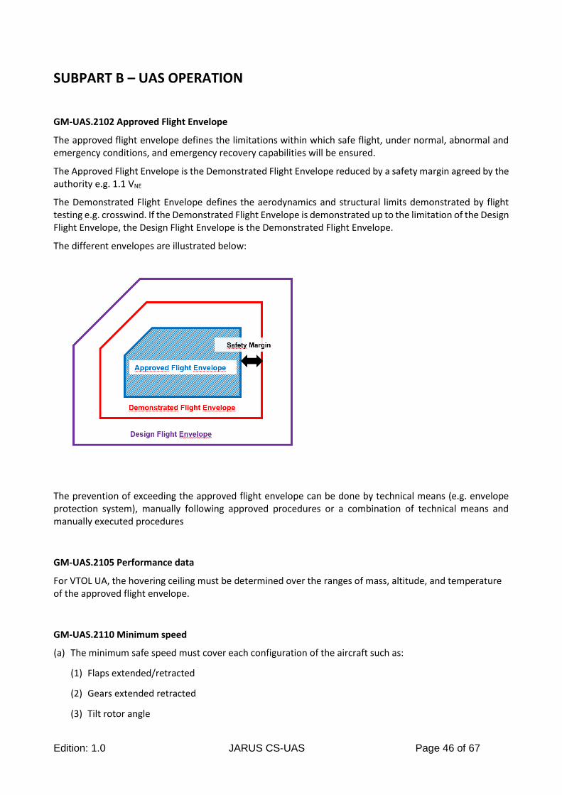
Edition: 1.0 JARUS CS-UAS Page 46 of 67
SUBPART B – UAS OPERATION
GM-UAS.2102 Approved Flight Envelope
The approved flight envelope defines the limitations within which safe flight, under normal, abnormal and emergency conditions, and emergency recovery capabilities will be ensured.
The Approved Flight Envelope is the Demonstrated Flight Envelope reduced by a safety margin agreed by the authority e.g. 1.1 VNE
The Demonstrated Flight Envelope defines the aerodynamics and structural limits demonstrated by flight testing e.g. crosswind. If the Demonstrated Flight Envelope is demonstrated up to the limitation of the Design Flight Envelope, the Design Flight Envelope is the Demonstrated Flight Envelope.
The different envelopes are illustrated below:
The prevention of exceeding the approved flight envelope can be done by technical means (e.g. envelope protection system), manually following approved procedures or a combination of technical means and manually executed procedures
GM-UAS.2105 Performance data
For VTOL UA, the hovering ceiling must be determined over the ranges of mass, altitude, and temperature of the approved flight envelope.
GM-UAS.2110 Minimum speed
(a) The minimum safe speed must cover each configuration of the aircraft such as:
(1) Flaps extended/retracted
(2) Gears extended retracted
(3) Tilt rotor angle
Edition: 1.0 JARUS CS-UAS Page 47 of 67
(4) External Cargo Loads
(b) Where the configuration can be changed during the flight, the minimum safe speed for the transition
must be determined
(c) The minimum safe speed must be determined for each flight phase such as:
(1) Take-off, climb, cruise, descent, approach, and landing
(2) Autorotation within the H-V Diagram out of ground effect, for autorotation capable UA
(3) Near obstacle flights
(d) The means to prevent exceeding the flight envelope must contain sufficient safety margin with regard
to the minimum safe speed
(e) For multi engine aircraft, the minimum speeds must be defined for the most critical failure
combination of engines and propellers, if any.
GM-UAS.2115 Take-off and minimum performance
For multi engine UA, the minimum performance must be evaluated and demonstrated in the most critical
configuration including the most critical combination of loss of propulsion.
GM-UAS.2120 Climb requirements
For multi engine UA designed for continued flight after a critical loss of propulsion, the applicant must determine climb performance accounting for the most critical combination of loss of propulsion in the most critical configuration.
GM-UAS.2125 Rate of descent performance
For UA not designed for continued safe flight and landing after a critical of loss of propulsion, the applicant must determine the rate of descent performance accounting for the most critical combination of loss of propulsion in the most critical configuration.
This rate of descent applies to any means employed to enable a controlled descent (e.g. : glide, autorotation, parachute, remaining operating engines).
GM-UAS.2135 Controllability and stability
The applicant must determine if there are any critical control parameters, such as VMC or control power margins, and if applicable, account for those parameters where appropriate to develop the respective ADS.
Where compliance demonstration to the performance requirements is based on data obtained by computation or modelling, the stability analysis must be supported by the results of relevant flight tests.
The means to protect against exceeding the demonstrated flight envelope must contain sufficient safety margin with regard to the controllability of the UA
Vortex ring state must be considered for VTOL capable UA
Applicant must demonstrate for VTOL capable UA the controllability in vertical operation and ability to land safely within the approved flight envelope.
Edition: 1.0 JARUS CS-UAS Page 48 of 67
GM-UAS.2160 Vibrations and buffeting
When developing the respective ADS, the high speed characteristics must be considered.
Edition: 1.0 JARUS CS-UAS Page 49 of 67
SUBPART C – STRUCTURES
GM-UAS.2200 Structural design envelope
(a) As far as the design speed envelope is concerned, the ADS must consider the following elements:
(1) for fixed wing configuration structural design airspeeds to be considered when determining the corresponding maneuvering and gust loads must:
(i) be sufficiently greater than the stalling speed of the UA to safeguard against loss of control in turbulent air; and
(ii) provide sufficient margin for the establishment of practical operating limiting airspeeds
(2) for VTOL and hybrid lift-configuration maximum UA flight speeds must be established:
(i) in any direction
(ii) for each rotor and rotating components, RPM within the established range
(b) For the ground loads, the ADS must also consider transportation, reconfiguration and storage (wind speed, light conditions, shock and vibration, water and moisture effect, particulate matter, electromagnetic fields, thermal conditions and wearing), where part of the approved operating envelope
(c) When defining UA design and operating parameters that affect structural loads, strength, durability, and aeroelasticity, credit may be taken for an installed automatic flight envelope protection system provided the requirement in CS-UAS.2205 is met
GM-UAS.2205 Interaction of systems and structures
In developing the ADS for this requirements the following elements must be considered:
(a) All systems that may affect structural performance must be evaluated under this requirement.
(b) In the analysis only failures not shown to be extremely improbable should be considered
(c) Severity and probability of failure conditions are defined according CS-UAS.2510
(d) The adjustment of safety factors required by CS-UAS Subpart C must be determined as a function of the failure probability and failure rate
(e) The limit loads must be derived at least at the following conditions
(1) System fully operative
(2) System in the failure condition at the time of occurrence
(3) System in the failure condition for the continuation of the flight
(f) Failure detection and indication must be provided
(g) Dispatch with known failed system
GM-UAS.2210 Structural design loads
In developing the ADS for this requirements the following elements must be considered:
Edition: 1.0 JARUS CS-UAS Page 50 of 67
(a) Structural design loads resulting from likely externally or internally applied pressure, force or moment which may occur in flight, ground and water operations, ground- and water- handling or transportation, and while the UA is parked, stored or moored
(b) The magnitude and distribution of these loads must be based on established physical principles or any other rationale accepted by the authority, within the structural design envelope
GM-UAS.2215 Flight load conditions
(a) As far as the critical flight loads are concerned, the ADS must consider the following elements in the boundaries of the maneuver and gust envelope:
(1) for fixed wing configuration:
(i) each altitude within the operating limitations, where the effects of compressibility are taken into account when significant
(ii) each mass from the design minimum mass to the design maximum mass
(iii) any practical but conservative distribution of disposable load within the operating limitations for each configuration of altitude and mass; and
(iv) the maximum design speed is expected to be greater than the design dive speed
(2) for VTOL and hybrid lift-configuration in addition:
(i) power-on and power-off flight with the maximum design rotor tip speed ratio,
(ii) for each configuration, the maximum design speed is expected to be either the designed dive speed or 1.1 VNE as appropriate
Note to CS-UAS.2215(b):
For rotary wing configurations:
Ground resonance can occur due to flexibility in the rotor pylon restraint system as well as with landing gear flexibilities. This mode of vibration or resonance can happen in flight (called air resonance) as well as on the ground and should be addressed in the certification program. The evaluation should include variations in stiffness and damping that could occur in service to the rotor pylon restraints.
GM-UAS.2220 Ground and water load conditions
(a) The loads in adverse landing conditions should be defined as the loads in normal landing conditions
multiplied by a load safety factor greater than 1 which accounts for the expected variability of the
landing manouvre
(b) As far as the ground resonance is concerned, the ADS must consider the following elements
(1) the probable range of variations, during service, of the damping action of the ground resonance prevention means, and
(2) any probable malfunction or failure of a single ground resonance prevention means
Edition: 1.0 JARUS CS-UAS Page 51 of 67
GM-UAS.2225 Component loading conditions
(a) As far as the component loading conditions are concerned, the ADS must consider, as a minimum, the
following structural components, if they are applicable for the configuration to be certified:
(1) rotor and rotating parts assembly
(2) structures
(3) rotor pylon
(4) fuselage
(5) landing devices
(6) powerplant and drive system
(7) propeller structures
GM-UAS.2240 Structural durability
The following conditions related to CS-UAS.2240(b) are examples which are considered impractical:
(a) Rapid or unstable propagation of the damage
(b) Insufficient accessibility to perform effective NDI
(c) NDI (Non Destructive Inspection) too complex for field use
CS-UAS.2240 (b) requires the design applicant to define methods to prevent catastrophic structural failure. This may include methods executed on ground or during flight (e.g. Health Usage Monitoring System).
GM-UAS.2252 Critical Parts
See FAA AC 27-1B Para. AC 27.602, as far as applicable and practicable to the UA configuration, to provide more information to develop the ADS.
GM-UAS.2255 Protection of structure
As far as parts related to CS-UAS.2255(b) are concerned, the ADS must include rotor blades and other rotating parts

Edition: 1.0 JARUS CS-UAS Page 52 of 67
SUBPART D – DESIGN AND CONSTRUCTION
GM-UAS.2305 Take-Off and Landing device systems
A take-off device system is a system whose function is to sustain the UA during the take-off phase on ground, allowing the UA to take-off.
A landing device system is a system whose function is to absorb the UA kinetic energy on ground during the landing phase and to sustain the UA in a proper attitude on ground until the complete stop.
Take-off and landing device systems may be fully or partially installed on the UA.A net system may be part of a landing device system.
GM-UAS.2320 Ground Crew Protection.
UAS high energy sources include any source of energy like mechanical, electrical or chemical energy.
Rotors, propellers and other high speed rotating parts should be considered.
Hazards coming from LRE energy sources should be taken into account as well.
GM-UAS.2325 Fire protection
The intent of CS-UAS.2325(b)(3) is that all combustible equipment, fluids and material which can be exposed to a potential ignition source, or are self-igniting and the risk of ignition or propagation cannot be mitigated according CS-UAS.2325(a) and (b)(1)&(2), is placed in a designated fire zone according CS-UAS.2330.
GM-UAS.2330 Fire protection in designated fire zones
(a) A designated fire zone is a zone on the UA within which it is assumed that a severe fire will occur
sometime in the service life of each UA
(b) A severe fire, when used with respect to fireproof materials, is one which reaches a steady state
temperature of 1100°C ± 65°C / 2’000 ± 150° F for at least 15 minutes
(c) A severe fire, when used with respect to fire resistant materials, is one which reaches a steady state
temperature of 1100°C ± 65°C / 2’000 ±150° F for at least 5 minutes
Note: Source: Severe Fire. The following thermodynamic definitions are based on AC 20-135, “Powerplant Installation and Propulsion System Component Fire Protection Test Methods, Standards and Criteria” and on the definitions in 14 CFR 1.1 for fire resistant and fireproof materials. These definitions are provided for analytical purposes.
GM-UAS.2335 Lightning protection
As different sets of requirements may apply to the UA and the RPS, different limitations may apply to the UA and the RPS with due consideration of respective Lightning Risk.
In order to determine that the exposure to lightning is unlikely, reliable weather forecast provided by a recognized Service Provider or onboard lightning detection means should be used.
Edition: 1.0 JARUS CS-UAS Page 53 of 67
GM-UAS.2350 Containment
(a) UA which rely on forced landing or controlled crash into a designated area as an emergency recovery procedure should be designed as far as practical so that –
(1) projection of parts (items of mass to be considered include, but are not limited to engines and payloads) that may constitute a potential injury to people, outside the designated area, is unlikely
(2) the UA does not constitute a source of ignition or leak of flammable fluids in hazardous quantities, and,
(3) any explosion after the forced landing must not constitute a hazard for people outside the designated area
GM-UAS.2360 Non-essential systems, equipment and installation
If the UAS design allows for removable non-essential systems and equipment to be installed by the installer/operator then the following must be defined by the type certificate applicant:
(a) Installation instructions and limitations, including installation interfaces to comply with the requirements of CS-UAS necessary to demonstrate the “no hazard” criteria
(b) Data describing eligibility and suitability for subsequent installation. Possible conditions and limitations data may include methods, procedures, sketches, drawings, photographs, etc.
(c) Instructions for Continued Airworthiness (ICA) including any data and information referred to in (a) and (b)
In defining the data in (a) and (b) above necessary to prove no hazard, the type certificate applicant should assess at a minimum the following –
(1) Mechanical and electrical interfaces with the UA
(2) Direct and indirect effects of any possible failure and malfunction, including structural failures and structural performance degradation, of the non-essential equipment, system and installation on any essential equipment, systems, installation and primary structure of the UAS;
(3) Direct and indirect effects of lightning, including zonal assessment
(4) Electromagnetic compatibility
(5) Effect on the flight performances, stability and controllability of the UA
(6) Aeroelasticity, including buffeting and vibration
(7) Mass and balance
(8) Effect on the ICA of the UAS
(9) Operating limitations
(10) Any other factors affecting the airworthiness of the UAS, the airspace rules or the operational rules
GM-UAS.2370 External Cargo Loads
“External cargo load” is any system intended to transport a mass connected externally to the UA by using
cable or otherwise tilting systems and related attaching means, which allow the transported mass to move
relative to the UA during flight. An external cargo loads can be either fixed or releasable.
Edition: 1.0 JARUS CS-UAS Page 54 of 67
SUBPART E – POWER PLANT INSTALLATION
GM-UAS.2400 Powerplant installation
Note-1: The CS-27 requirement for fuel tank passenger protection in case of a hard landing is not
applicable. Particular considerations for UA in case of forced landing are addressed through the
Containment Requirement CS-UAS.2350.
Note-2: Rotor drive system should be covered by CS-UAS.2400 (c)(4) and (5) as the CS-27 requirements
has mainly requirements concerning vibration, fatigue and endurance.
If the installed engines or propellers and APU do not have their own TCs the ADS should include the
corresponding requirements coming from CS-E, CS-P and CS-APU or equivalent specifications (e.g. for
electric propulsion).
GM-UAS.2430 Powerplant installation, energy storage and distribution systems
The intent of the requirement is to ensure the physical installation of the energy storage and distribution system is designed and installed such that it can perform its intended function.
Energy distribution systems are all elements included in the distribution of the energy to the powerplant system, independent of whether the energy is fuel, electrical power hydrogen etc. As a consequence, the power wires of an electrical powerplant system are part of the distribution system.
GM-UAS.2435 Powerplant installation support systems
For compliance with this requirement Powerplant installation support systems:
(a) Are all systems whose direct purpose is to support the powerplant or the energy storage device in its intended function as part of the powerplant installation. This includes any air intake, exhaust or venting system
(b) That have a direct effect on the engine availability must be considered in the engine reliability
Edition: 1.0 JARUS CS-UAS Page 55 of 67
SUBPART F – SYSTEMS AND EQUIPMENT
GM-UAS.2500 UAS level system requirements, GM-UAS 2505 General requirements on equipment installation, GM-UAS 2510 Equipment, systems and installations
In developing the ADS, the JARUS AMC RPAS.1309 (or an equivalent AMC recognized by the Competent Authority) should be considered.
GM-UAS.2515 Electrical and electronic system lightning protection
The lightning environment shall be appropriate for the approved operation and agreed by the authority.
The concept of continued safe flight and landing or emergency recovery of the UA should include, that the UA remains within the approved flight envelope, the intended flight path and within all spatial limitations when the UAS is exposed to lightning strikes.
GM-UAS.2520 High-Intensity Radiated Fields (HIRF) Protection
The HIRF environment of the UAS shall be appropriate for the approved operation and agreed by the authority.
The concept of continued safe flight and landing or emergency recovery of the UA should include, that the UA remains within the approved flight envelope, the intended flight path and within all spatial limitations when the UAS is exposed to HIRF.
GM-UAS.2522 Cyber Security
The UAS operational requirements may include cyber security requirements as needed. The "EASA AMC 20-42: Airworthiness information security risk assessment" can be used as possible guideline to develop the ADS.
GM-UAS.2525 UAS power supply, generation, storage, and distribution
With respect to the RPS, the intent of the objective requirement is not to approve any power generation system supplying the RPS. The intent is to verify the performance of the RPS power source.
GM-UAS.2530 UA External lights
In subparagraph (c ) sufficient guidance for the intended operations includes operations at night or with low visibility
GM-UAS.2529 UA Flight Control System
UA Flight Control System refers to Pilot functions performed by electronic equipment according to predefined rules
1. The spatial limitations may be ensured by geo-fencing or any other technical means to prevent the aircraft to violate the spatial limitations
Edition: 1.0 JARUS CS-UAS Page 56 of 67
2. All flight phases contains all self-movements of the UA including taxi out of the starting position to a stop at the final position, where this is part of the normal operation. An evaluation of the take-off and landing system is therefore required
3. For UA with trim capability, the Flight Control System (FCS) must trim the UA in such a manner that a maximum of control remains and that dynamic characteristics and safety margins are not compromised
4. In case the UAS requires a crew for safe operation:
a. The UA control system comprises the equipment for the command and control between the UA and the RPS
b. The UA control system must provide an alert to the crew for any loss or degradation of the UA control system which would affect the ability to safely operate the UA
GM-UAS.2540 Flight in icing conditions
If an ice protection system is installed, the ADS must consider the following:
(a) Protection against an accumulation of ice beyond the structural and performance limitations
(b) Ice shedding will not create any hazard to the UA
(c) Effects of the icing protection system to the structure and UA performance must be evaluated
GM-UAS.2555 Installation of recorders
The ADS must consider that:
(a) The recorder includes features to locate the memory medium after an accident
(b) The recorder is powered by the most reliable power source and remains powered for as long as possible without jeopardising service to essential or emergency loads and emergency operation of the UAS
GM-UAS.2570 Emergency Recovery Capability and Procedures
The aim of the requirement is to ensure the UAS is capable to perform Emergency Procedures either by the remote pilot or automatically by the on-board systems.
(a) The Emergency Recovery Capability and Procedures (ERCP) must:
(1) Perform the Emergency Procedures automatically according to the requirements for certification for scenarios when the pilot has lost the ability to perform them remotely (lost link, RPS failure, vortex ring state etc.)
(2) Achieve the safety targets in accordance with CS-UAS.2500 through CS-UAS.2510. This may create the need for operating limitations
(3) Comply with operational requirements
(b) The Emergency Recovery Capability and Procedures may consist of the following:
(1) Controlled flight termination system or function:
i) To reduce the impact energy to an acceptable level
ii) For a forced landing to an area with an acceptable low population density (down to zero population density)
Edition: 1.0 JARUS CS-UAS Page 57 of 67
iii) To reduce the impact energy together with the population density of the forced landing area such that the risk of fatal injuries on ground caused by the UA, possible debris, fire or explosions is acceptable
(2) Predictable continuation of the flight supported by Emergency Procedures:
i) For a continuation of the flight with the use of on-board systems and either internal or external DAA capability where manual control is no longer possible
ii) On a predefined path which will be cleared from all other air traffic or which is free from air traffic, which will be followed either manually, or performed by the on-board systems
(3) Any combination of (b)(1) and (b)(2)
(4) Any other procedure or technical means accepted by the authority to fulfil the requirement in CS-UAS.2570
(c) The credit that can be given for the Emergency Recovery Capability and Procedures in relation to other design requirements must be agreed by the authority
(d) Reserved
(e) Critical infrastructures should be defined in accordance with the State where operations are carried out. The ADS could provide detailed definitions
GM-UAS.2575 Command, Control and Communication Contingency
(a) The intent of this requirement is to have procedures and/or technical functionalities on board in
case of a total loss or degraded command and control function. This includes emergencies in the
RPS and its environment where the crew is required to evacuate the RPS.
The basic assumptions for this rule are:
(1) The quality of the “signal in space” cannot be guaranteed. Only the equipment involved in transmitting and receiving the “signal in space” can be certified
(2) A total loss or degradation does not necessarily mean the Emergency Recovery Capability and Procedure in accordance with CS-UAS.2570 needs to be initiated immediately
(3) The transition times before the UA begins the contingency procedures due to the command and control function loss must be consistent with the Emergency Recovery Capability and Procedure established in accordance with CS-UAS.2570. The transition times which are needed to safely perform the Contingency Procedures must be specified in the Flight Manual for the crew
(b) After the total loss of the command and control function or a degradation to a point where remote
active control of the UA in a timely manner appropriate to the airspace and operating conditions is
no longer ensured.
(1) The Remote Pilot Station (RPS) must provide an alert to the crew, and
(2) The onboard system shall execute pre-defined procedures. These pre-defined procedures may
contain:
i) Procedures to re-establish the command and control function to the original or any
other available RPS
Edition: 1.0 JARUS CS-UAS Page 58 of 67
ii) Execution of an Emergency Recovery Capability and Procedure in accordance with CS-
UAS.2570
iii) Procedures to safely continue the flight without activating the ERC by utilizing onboard
installed systems
iv) Any combination of (i) through (iii)
Edition: 1.0 JARUS CS-UAS Page 59 of 67
SUBPART G – CREW INTERFACE AND OTHER INFORMATION
GM-UAS.2600 Remote Pilot Station (Performance)
(a) The physical parameters (e.g. size, temperature, power supply, earth bonding, maximum capacity …) deemed as essential for operation and that define the infrastructure suitable for the control station must be stated in the UAS Flight Manual
(b) The RPS equipment operating conditions (temperature, humidity, air quality, ventilation, vibration, noise, heat emissions …) must be adequate to allow the safe execution of the flights under the established conditions in (a)
(c) In non stationary RPS the effect of RPS motion must be considered
(d) The remote pilot station should provide an unimpeded and rapid escape to the crew (see GM-UAS.2575)
GM-UAS.2605 Remote Pilot Station (Human Factors)
The RPS equipment should be shown, individually and in combination with other such equipment, to be designed so that qualified remote crew members trained in its use can safely perform their tasks associated with its intended function by meeting the following requirements:
(a) controls should be designed to allow accomplishment of these tasks and information necessary to accomplish these tasks should be provided
(b) controls and information intended for crew use should:
(1) Be presented in a clear and unambiguous form, at resolution and precision appropriate to the task
(2) Be accessible and usable by the crew in a manner consistent with the urgency, frequency, and duration of their tasks
(3) Be plainly marked as to its function and method of operation, except these controls whose function is obvious, and
(4) Enable crew awareness, if awareness is required for safe operation, of the effects on the UA or systems resulting from crew actions
(c) Operationally-relevant behaviour of the installed equipment should be:
(1) Predictable and unambiguous, and
(2) Designed to enable the crew to intervene in a manner appropriate to the task
(d) The equipment should allow the crew member to perform his duties without unreasonable concentration, fatigue or workload.
(e) To the extent practicable, installed equipment should enable the crew to manage errors resulting from crew interactions with the equipment that can be reasonably expected in service, assuming the crew is acting in good faith
(f) The crew work place conditions (temperature, humidity, air quality, ventilation, vibration, noise, heat emissions …) must be adequate to allow the safe execution of the flights
(g) The crew work place lights, if available must:
Edition: 1.0 JARUS CS-UAS Page 60 of 67
(1) make each indicator, data display, information, markings, placard and control easily readable and discernible
(2) be installed so that their direct rays, and rays reflected from any surface, are shielded from the crew’s eyes
(h) Physical security requirements must be developed as needed within the ADS to protect the RPS and the crew (e.g. access control) from intentional unauthorized acts that may prevent continued safe flight and landing or emergency recovery.
GM-UAS.2615 Flight, navigation, and powerplant instruments
If it is desired to hide some parameters from full-time display, an equivalent level of safety to full-time display shall be demonstrated. Criteria to be considered include the following :
(a) Continuous display of the parameter is not required for safety of flight in all normal flight phases.
(b) The parameter is automatically displayed in flight phases where it is required
(c) The hidden parameter is automatically displayed when its value indicates an abnormal condition, or when the parameter reaches an abnormal value
(d) Display of the hidden parameter can be manually selected by the remote crew without interfering with the display of other required information
(e) If the parameter fails to be displayed when required, the failure effect and compounding effects should meet the requirements of CS-UAS.2500 up to 2510. The analysis is to clearly demonstrate that the display(s) of data is consistent with safe operation under all probable operating conditions
(f) The automatic, or requested, display of the hidden parameter should not create unacceptable clutter on the display; simultaneous "pop-ups" should be considered
(g) If the presence of the new parameter is not sufficiently self-evident, suitable alerting should accompany the automatic presentation
GM-UAS.2620 (a) UAS Flight Manual
The procedures to be covered by the ADS must consider:
(a) Normal procedures
(b) Abnormal procedures
(c) Emergency procedures
(d) Procedures for launch and recovery systems or equipment
GM-UAS.2625 Instructions for Continued Airworthiness (ICA)
CS-UAS.2625 (a) applies for all systems (powerplant, mechanical-, electrical-, electronical-, hydraulic-, pneumatic- etc. system).
Edition: 1.0 JARUS CS-UAS Page 61 of 67
SUBPART H – ANCILLARY SYSTEMS
GM-UAS.2710 Systems for Launch and Recovery not permanently installed on the UA
This requirement applies to systems required for the launch and recovery of the UA which are not permanently installed and may be used for multiple UA’s. The equipment which is part of these systems is known as Launch and Recovery Equipment (LRE).
The Launch and Recovery Equipment even not permanently installed on the UA is part of the UAS and therefore the requirements CS-UAS.2500 up to 2510 apply.
The launch phase ends when the UA leaves the flight safety area associated to the launch safety area required in CS-UAS.2710.
CS-UAS.2710(b) applies as well for recovery systems required by CS-UAS.2570.
The energy referred to in CS-UAS.2710(a)(1) and (b)(1) includes all types of energy required for a safe launch or recovery of the UA.
The intent is to open two options for the launch and recovery system (LRE) with relation to the launch or recovery safety area in (a)(3) and (b)(3):
(1) For systems where only the performance of the LRE is defined the requirements in Subpart C and Subpart D may be met by equivalent level of safety. Therefore the structural integrity of the LRE may not be ensured and the loss of the structural integrity of the LRE must be considered in the calculation of the safety area
(2) All parts of the LRE for which strength degradation could result in fatal injuries or loss of the UA must comply with the applicable requirements in Subpart C and Subpart D. Therefore the structural integrity of the LRE is ensured and the loss of the structural integrity of the LRE need not be considered in the calculation of the safety area
Edition: 1.0 JARUS CS-UAS Page 62 of 67
4. ANNEXES
Annex A - High Level Standardised Mitigations (HLSM)
The certification basis can be adapted if the operation is constrained by technical or operating limitations, so that the risk to third parties on the ground or in the air requires no further mitigation.
Predefined prescriptive operating or technical limitations were developed to alleviate certain requirements of CS-UAS.
HLSM.1 Operations are conducted over an unpopulated area
(a) Operations are carried out over an unpopulated area with zero population density
(b) Operations are carried out over a populated area with no exposed people (e.g. due to sheltering
factor or time/calendar reasons)
General Requirements
− The UA remains in the area either by
o GEO Fencing + any required buffer, or
o Energy limitation to prevent the UA to exit the defined volume, or
o A combination of the above
− Area remains unpopulated
o Operator has access control over the area, or
o Population density monitoring capability (ground based or air based), or
o Area is not accessible by nature
⮚ Information in the TCDS: For operation over unpopulated area only
⮚ Information in AMC UAS: Information about “Aircraft remains in the area” & “Area remains
unpopulated”
❖ Only the GEO-Fencing/Energy Limitation must be certified in accordance with CS-UAS
❖ In case of a forced landing, the forced landing area must fit into the operation area (e.g. CS-
UAS.2350 Containment)
❖ This HLSM is not applicable to compensate for the air risk
HLSM.2 Operations are conducted over low population density area
(a) Population density in the area of operations, including the buffer, is sufficiently low so that the risk
of third party injury is below an acceptable level, based on the results of an accepted risk assessment
(b) Population density level in conjunction with a pre-planned flight path and scheduled times of flight
(exposure times) is so that the risk of third party injury is below an acceptable level, agreed by the
authority, based on the results of an accepted risk assessment
(c) A contingency control plan is put in place, in cooperation with the competent territorial bodies, in
order to assure the ground control of the area of operations, e.g. in terms of segregation and fencing,
route or railway coordination, awareness and information of the population etc.
Edition: 1.0 JARUS CS-UAS Page 63 of 67
(d) There are reliable and proven means to allow exposed people to escape and avoid the risk of injury
in the event of loss of control of the UA
General Requirements
− The UA remains in the area either by:
o GEO Fencing and any required buffer, or
o Energy limitation to prevent the UA to exit the defined volume, or
o A combination of the above
− Area remains low populated.
o Definition of low population density, and
o Population density monitoring capability (ground based or air based), and
o Minimum Flight Altitude related to the local population density (allows to climb in case a
local higher population density should be overflown. The additional height provides more
time for the ERCP)
⮚ Information in the TCDS: For operation over low populated area only
⮚ Information in AMC UAS: Information about “Aircraft remains in the area” & “Area remains low
populated”
❖ Only the GEO-Fencing/Energy Limitation must be certified in accordance with CS-UAS
❖ In case of a forced landing, the forced landing area must fit into the operation area (e.g. CS-
UAS.2350 Containment)
❖ This HLSM is not applicable to compensate for the air risk
HLSM.3 Empty Airspace (segregated)
General Requirements
− The UA remains in the area either by:
o GEO Fencing + any required buffer, or
o Energy Limitation to prevent the UA to exit the defined volume, or
o A combination of the above
− Area remains empty
o Restricted Area published
o Remote Area with no air traffic
o Other Areas with no air traffic
⮚ Information in the TCDS: This UA is only certified for use in segregated or empty airspace
❖ Only the GEO-Fencing/Energy Limitation is certified
❖ Procedures to ensure the airspace remains “empty” are required
❖ In case of a forced landing, the forced landing area must fit into the operation area (e.g. CS-
UAS.2350 Containment)
❖ This HLSM is not applicable to compensate for the ground risk
Edition: 1.0 JARUS CS-UAS Page 64 of 67
HLSM.4 Harmless characteristics
(a) The injury threshold which can be accepted as harmless must be defined by the competent authority
based on an accepted injury scale.
(b) The UA is harmless in any condition to people on the ground.
(c) The UA is harmless to other airspace users.
(d) The concept of this HLSM is to prevent injuries to an acceptable level by design and material
characteristics. This may require additional operating limitations.
(e) The effectiveness of a single mitigation or a combination of several mitigations must be proven.
(f) Systems may be used to reduce the kinetic energy at impact or alert people on the ground.
General Requirements
1. Material and Design characteristics must be so that the Energy at Impact to a human body is
reduced to prevent injuries above the level accepted by the authority; or, UAS must be
designed so that any impact with a human body does not result in injuries above the level
accepted by the authority.
2. High density or rigid material must be contained within the UA in case of an impact and
constrained within the original location during all flight manoeuvres within the Operational
Flight Envelope
3. Must incorporate design features which reduce the possibility of post-crash fire which results
in injury to people
4. Must incorporate design features which reduce the possibility of in-flight fire
5. No Dangerous Goods transportation
Edition: 1.0 JARUS CS-UAS Page 65 of 67
Annex B - Multiple UA’s controlled simultaneously by a single RPS and multiple RPS controlling multiple UA’s
RESERVED
Edition: 1.0 JARUS CS-UAS Page 66 of 67
Annex C - Non-deterministic UA
RESERVED
Edition: 1.0 JARUS CS-UAS Page 67 of 67
Annex D - Transportation of humans and livestock
RESERVED