Embed Size (px)
Citation preview

JDN GENERAL CATALOGUE

3
CONTENTs
JDN Company Portrait 4 The Company 4 Environmental Protection and Quality 5
JDN Air Hoists mini 6 The mini series at a glance 6 mini 125 – mini 1000 7-8
JDN Air Hoists Profi 9 The modular system at a glance 10
PROFI 025 TI – 2 TI 11
PROFI 1.5 TI – 3 TI/2 12
PROFI 3 TI – 20 TI 13
PROFI 25 TI – 100 TI 14
JDN Air Hoists M Series 15
JDN Trolleys 16-17 PROFI in Manual Trolley (LN) 18
PROFI in Reel Chain Trolley (LH) 19
PROFI in Motor Trolley (LM) 20
JDN Low Headroom Trolleys 21-22
JDN Big Bag Handling Air Hoists 23-25
JDN Monorail Air Hoists 26-29
JDN Ultra-Low Monorail Hoists 30-31
JDN BoP Handling Systems 32
JDN Hoists for use in the toughest conditions 33
JDN Subsea Hoists 33
JDN Cryogenic Hoists 33
JDN Hydraulic Hoists and Monorail Hoists 34 PROFI 3 TI-H – 20 TI-H 35
PROFI 25 TI-H – 100 TI-H 36
EH 20-H – EH 100-H 37
JDN Crane Systems/Crane Kits 38
JDN Explosion Protection 39
JDN Accesssories 39
JDN Controls 40-41
JDN Energy Supplies 42-44
JDN Service 45-46

4
JDN COmpANy pORTRAiT
At its Witten location, J.D. Neuhaus with 150 employees produces hoists and crane systems which are mainly driven by com-pressed air.
Thanks to this globally unique specialisati-on and our more than 50-years of expertise with compressed air as a drive medium, we have become a recognised expert in the field. Today, our share of exports is 80%. In total, we export to more than 90 countries around the globe. Our sales companies in the USA, Great Britain, France and Singapore support our customers at local level.
J.D. Neuhaus air hoists and hydraulic hoists are now used in more than 70 diffe-rent industries. Demand for our products is particularly high in the oil and gas exploration and processing sectors, in mining, the chemical industry and heavy plant construction.
The complete JDN production range includes a total of 12 product lines, which are precisely adapted to their respective areas of application and requirements in terms of load capacity. Moreover, we consis tently set new standards with customised solutions for exceptional applications.
The Company

5
Environmental Protection and Quality
Starting with the development and produc-tion of our products, we place great value on ecological compatibility. Long service life and recyclability already make an important contribution towards relieving the environmental burden.
Furthermore, our production has been adapted to minimise energy consumption, emissions, sewage and waste; it also uses environmentally-compatible production processes and materials. Resources are used sparingly and waste is recycled wherever possible.
One of the most important commitments of the J.D. Neuhaus management is to promo-te awareness, openness and a sense of responsibility among employees in order to establish conditions favourable to the implementation of our environmental guide lines. We have also made environ-mental protection a permanent feature of our employee training courses.
In December 2009 we received ISO 14001 certification from the TÜV Rheinland Technical Control Association for our extensive environment management system.
Our quality management system covers all our processes, from planning and design through to production and customer service. It is also certified by the TÜV Rheinland according to ISO 9001.

6
JDN AiR HOisTs miNi
The mini series at a glance
Galvanised chain 3 standard lifting heights
Sensitive control3 standard control lengths
Explosion classificationII 3 GD IIA T4
Manual trolleys
Special grease for oil-free operation
Mini tool box consisting of: mini with 3 m lift and 2 m control length in practical transport box incl. 6 m supply hose and couplings
Energy supply (spiral hose)
mini in manipulator version

7
The JDN mini series for general duty Capacities: 125 kg, 250 kg, 500 kg, 980 kg Air pressure: 6 bar
Type mini 125 mini 250 mini 500 mini 1000
Capacity lbs� kg
275� 125
5�5�0 250
1100 500
2160 980
Air pres�s�ure PSI� bar
85� 6
85� 6
85� 6
85� 6
Number of chain s�trands� 1 1 1 1Motor output kW 0.4 0.4 1 1Lifting s�peed at full load1 ft/min
m/min49.5� 15
26 8
33 10
16 5
Lifting s�peed without load1 ft/min m/min
130 40
65� 20
65� 20
33 10
Lowering s�peed at full load ft/min m/min
99 30
5�2 16
5�9 18
33 10
Lowering s�peed without load ft/min m/min
78.7 24
39.4 12
39.4 12
19.7 6
Air cons�umption at full load – lifting cfm m3/min
17.5� 0.5
17.5� 0.5
42.5� 1.2
42.5� 1.2
Air cons�umption at full load – lowering cfm m3/min
24.7 0.7
24.7 0.7
5�6.5� 1.6
5�6.5� 1.6
Air connection G 3/8 G 3/8 G 1/2 G 1/2
Hos�e dimens�ion (Ø ins�ide) inch mm
3/8 9
3/8 9
1/2 13
1/2 13
Weight with 10 ft / 3 m lift lbs� kg
21 9.5
23.1 10.5
46.2 21
5�0.6 23
Chain dimens�ion mm 4 x 12 4 x 12 7 x 21 7 x 21Weight of chain lbs�/ft
kg/m0.23 0.35
0.23 0.35
0.67 1.0
0.67 1.0
Height of lift ft m
10/16/26 3/5/8
Length of control at s�tandard lift ft m
6.5�/13/20 2/4/6
Nois�e level at full load2 – lifting dB(A) 79 79 77 77Nois�e level at full load2 – lowering dB(A) 80 80 83 83
Technical Data
Group mechanis�m: M3 (1 Bm)1 Lifting s�peed at 2 m length of control. Longer control hos�es� decreas�e the lifting s�peeds�.2 Meas�ured at 1 m dis�tance acc. to DI�N 45�635� part 20
mini 250
The advantages at a glance
Price competitive alternative when com-pared to other types of powered hoists.
Suitable for lube-free operation.
Suitable for application in hazardous areas.
Minimum components for ease of maintenance.
Wear resistant motor braking system.
Lightweight for easy handling.
Also suitable for horizontal pulling.
Extremely sensitive lever control with emergency shut-off valve, max. control length 6 m.
Available lifting heights: up to 8 m.
With chain box as standard.
With manual trolley as option.
The mini widens the range of applications in the light duty sector as a handy, flexib-le and universally deployable hoist making it an ideal tool for a wide range of light/medium manufacturing applications.
mini ManipulatorWith the mini manipulator loads can be lifted, lowered, manually traversed and positioned with only one hand. Further information on request.
Explosion Classification: II 3 GD IIA T4mini-Manipulator
mini 250in manual trolley

8
Dimensions
Technical Data
Manual Trolleys for JDN Air Hoists mini
Type mini 125 mini 250 mini 500 mini 1000
A inch mm
12.9 328
12.9 328
18.0 458
18.0 458
B inch mm
9.1 232
9.1 232
12.4 316
12.4 316
C inch mm
14.4 367
14.4 367
19.9 505
19.9 505
D inch mm
3.6 92
3.6 92
4.8 122
4.8 122
E inch mm
8.4 213
8.4 213
11.5� 292
11.5� 292
F inch mm
4.3 109
4.3 109
5�.8 148
5�.8 148
G inch mm
4.1 104
4.1 104
5�.6 144
5�.6 144
H inch mm
7 177
7 177
9.2 234
9.2 234
J inch mm
5�.8 148
5�.8 148
7.6 194
7.6 194
K inch mm
3.3 83
3.3 83
4.7 119
4.7 119
L inch mm
1.1 29
1.1 29
1.6 40
1.6 40
M inch mm
0.7 19
0.7 19
1.1 28
1.1 28
Type LN 250 LN 1000
Capacity lbs� kg
5�5�0 250
2200 1000
Beam flange width b inch mm
2-8 50-220
2-8 58-220
max. flange thicknes�s� t inch mm
1.2 30
1.0 25
min. curve radius� inch m
35�.4 0.9
39.4 1.0
Weight lbs� kg
17 7.7
21 10.5
Type LN 250 LN 1000
A inch mm
3.1 79
3.1 79
D inch mm
0.7 17
0.7 17
D1inch mm
1 25
1.2 30
D2inch mm
1.2 30
1.4 35
H1inch mm
1.2 30
1 25
I� inch mm
2.7 67.5
3.2 81.5
L inch mm
10.2 260
10.2 260
L1inch mm
5�.1 130
5�.1 130
O inch mm
2.2 55
2.7 68
T inch mm
5�.7 144
5�.9 151
Dimensions
E
F
C A
B
D
M
K L
JH
M
T
b
D
D2
D1
A
H1
O
I
t
L
L1
JDN AiR HOisTs miNi
G

9
JDN AiR HOisTs pROFi
Capacities: 250 kg up to 100 tAir pressure: 4 bar or 6 bar
Proven in practice: JDN Air Hoists Profi Series are superior in all places where safety has priority. The Profi Series scores well with its 100% duty rating and explosion protection as standard. This important advantage ensures JDN Air Hoists are especially suitable for applications in hazardous areas.
JDN Air Hoists Profi Series are very robust and therefore suitable for tough industrial applications even in continuous working processes. According to your requirements there are various control systems available. For traversing loads there are also different trolley designs to meet your particular demands.
Where the JDN Profi excellence has been proven
Aircraft construction, assembly lines, chemical industry, dairies, electro plating, explosives and pyrotechnics industry, food industry, foundries, furniture industry, glass industry, lacquer and varnish factories, match industry, mechanical engineering, auto industry, oil storage plants, on- and offshore, paint shops, paper industry, power plants, refineries, sawmills, shipyards, space industry, tempering plants, textile industry.
Standard features Suitable for application in hazardous
areas
Sensitive infinitely variable speed con-trol for the precise positioning of loads
Easy operation
Suitable for lube-free operation
100 % duty rating and unlimited duty cycles
Low maintenance
Low headroom, lightweight
Sound absorption
Insensitive to dust, humidity and tempe-ratures ranging from -20°C up to +70°C
From 1t upwards with overload protec-tion (EC-version)
Technical Details
Fail-safe starting, low maintenance vane motor
Chain sprocket in the mid section runs in dust-proof maintenance-free ball bearings
Planetary gear box with long-life grease lubrication, all gears made of tempered or hardened high-grade steel
Load chain and hooks manufactured from high quality tempered steels with a breaking strength of five times the nominal load
The advantages at a glance
Strong – fast – Silent High performance with more efficiency
by reliability plus high lifting and lowering speeds. Low sound emissions.
High Level of Safety Integrated emergency stop switch
from 1t upwards with overload protection.
oil-free operation Patented, permanent motor lubrication
during operation, using a high-perfor-mance grease. No additional motor lubri-cation required.
Patented Motor-Brake System For operation with low maintenance and
little wear. Based on the proven design of the JDN Mini Series.
Modern Design – Compact Size Features no protruding control hoses
or parts susceptible to damage, making the PROFI also suitable for horizontal pulling.
100% Duty rating – No Downtime
Ex Classification according to EC Directive on Hazardous Locations 94/9/EEC
As standard:
II 2 GD IIA T4/II 3 GD IIB T4 With increased spark protection:
II 2 GD IIC T4

10
JDN AiR HOisTs pROFi
filter Silencer
Chain Container Chain Box
Chain Bag
Hook Standard
Copper-plated
Stainless Steel
Controls Rope Control
FI Control (sensitive)
E Control (single speed)
F Control (multi-function)
Remote Control
Electropneumatic Interface
Special High Performance Greasefor oil-free operation
Supply Hose Trolleys
Spiral Hose
Energy Chain
C-rail
Square Bar
Limit Switch for Lift
Trolleys Manual Trolley
Reel Chain Trolley
Motor Trolley
Housing finish Standard JDN Green
4-coat offshore paint system
Service Unitfilter regulator
The modular system at a glance
Limit Switch for Trolley TravelExtension Arm for Control
Ex ClassificationStandard:
II 2 GD IIA T4/II 3 GD IIB T4
With increased spark protection: II 2 GD IIB T4
With increased spark protection for explosion group IIC:
II 2 GD IIC T4

11
PROFI 1TI
Type 025 Ti 05 Ti 1 Ti 2 TiCapacity mt 0.16 0.25� 0.32 0.5� 0.63 1 1.25� 2
Air pres�s�ure PSI� bar
65� 4
85� 6
65� 4
85� 6
65� 4
85� 6
65� 4
85� 6
Number of chain s�trands� 1 1 1 2
Motor output kW 0.6 1.0 0.6 1.0 0.6 1.0 0.6 1.0
Lifting s�peed at full load ft/min m/min
65�.6 20
65�.6 20
32.8 10
36.1 11
16.4 5
18 5.5
8.2 2.5
8.9 2.7
Lifting s�peed without load ft/min m/min
123 37.5
137.8 42
5�2.5� 16
62.3 19
32.8 10
36.1 11
16.4 5
18 5.5
Lowering s�peed at full load ft/min m/min
124.7 38
124.7 38
5�5�.8 17
5�5�.8 17
32.8 10
36.1 11
16.4 5
18 5.5
Air cons�umption at full load – lifting
cfm m3/min
24.7 0.7
42.4 1.2
24.7 0.7
42.4 1.2
24.7 0.7
42.4 1.2
24.7 0.7
42.4 1.2
Air cons�umption at full load – lowering
cfm m3/min
28.3 0.8
5�3 1.5
28.3 0.8
5�3 1.5
28.3 0.8
5�3 1.5
28.3 0.8
5�3 1.5
Air connection G 1/2 G 1/2 G 1/2 G 1/2
Hos�e dimens�ion (ø ins�ide) inch mm
1/2 13
1/2 13
1/2 13
1/2 13
Weight with s�tandard lift, rope control
lbs� kg
5�9.5� 27
5�9.5� 27
5�9.5� 27
5�9.5� 27
61.6 27.5
61.71 281
75�1
34175�1
341
Chain dimens�ion mm 7 x 21 7 x 21 7 x 21 7 x 21
Weight of chain lbs�/ft kg/m
0.67 1.0
0.67 1.0
0.67 1.0
0.67 1.0
Standard lift ft m
10 3
10 3
10 3
10 3
Lenght of control at s�tandard lift ft m
6.5� 2
6.5� 2
6.5� 2
6.5� 2
Nois�e level at full load2 – lifting dB(A) 73 74 74 75� 74 76 74 76Nois�e level at full load2 – lowering dB(A) 77 78 77 78 77 78 77 78
1With overload protection 2Meas�ured at 1 m dis�tance acc. to DI�N 45�635� part 20Group mechanis�m at 6 bar: PROFI� 025�TI� M5� (2 m), PROFI� 05�TI� - PROFI� 2TI� M4 (1 Am)
Type 025 Ti 05 Ti 1 Ti 2 Ti
A min. headroom1 inch mm
17.7 450
17.7 450
17.7 450
19.6 498
B inch mm
11.3 288
11.3 288
11.3 288
13.2 336
C inch mm
5�.7 145
5�.7 145
5�.7 145
5�.7 145
D inch mm
11.7 297
11.7 297
11.7 297
11.7 297
E1inch mm
1.1 28
1.1 28
1.1 28
1.1 28
E2inch mm
1.1 28
1.1 28
1.1 28
1.1 28
F up to hook centre inch mm
5�.4 137
5�.4 137
5�.4 137
5�.4 137
G maximum width inch mm
6.9 176
6.9 176
6.9 176
7.2 183
Technical Data
Dimensions
Profi 025Ti – 2Ti
G
F
DC
A
B
E1
E2
1Chain containers� increas�e the hois�t headroom

12
bar
PSI
65
85
6
4Air pressure range:
1Meas�ured at 1 m dis�tance acc. to DI�N 45�635� part 20Group mechanis�m: M3 (1 Bm)
1Chain containers� increas�e the hois�t headroom
Type 1.5 Ti 3 Ti/2
A min. headroom1 inch mm
18.9 480
21.4 544
B inch mm
11.5� 293
14.0 356
C inch mm
7.9 200
7.9 200
D inch mm
16.2 412
16.2 412
E1inch mm
1.1 28
1.1 28
E2inch mm
1.0 26
1.1 28
F up to hook centre inch mm
6.7 170
5�.5� 140
G maximum width inch mm
8.5� 215
8.5� 215
Type 1.5Ti 3 Ti/2Capacity mt 1.6 3.2
Air pres�s�ure range PSI� bar
65�-85� 4-6
65�-85� 4-6
Number of chain s�trands� 1 2Motor output kW 1.3-2 1.3 - 2
Lifting s�peed at full load ft/min m/min
13.1-19.7 4-6
6.6-9.8 2-3
Lifting s�peed without load ft/min m/min
27.6-32.8 8.4-10
13.8-16.4 4.2-5
Lowering s�peed at full load ft/min m/min
36.1-39.4 11-12
18.0-19.7 5.5-6
Air cons�umption at full load – lifting
cfm m3/min
5�3-92 1.5-2.6
5�3-92 1.5-2.6
Air cons�umption at full load – lowering
cfm m3/min
78-127 2.2-3.6
78-127 2.2-3.6
Air connection G 3/4 G 3/4
Hos�e dimens�ion (Ø ins�ide) inch mm
3/4 19
3/4 19
Weight with s�tandard lift, rope control
lbs� kg
123 56
146 66
Chain dimens�ion mm 9 x 27 9 x 27
Weight of chain lbs�/ft kg/m
1.2 1.8
1.2 1.8
Standard lift ft m
10 3
10 3
Lenght of control at s�tandard lift ft m
6,5� 2
6,5� 2
Nois�e level at full load1 – lifting dB(A) 73-77 73-77Nois�e level at full load1 – lowering dB(A) 78-80 78-80
Technical Data
Dimensions
PROFI 1.5TI PROFI 3TI/2
Profi 1.5Ti and 3Ti/2
GF
DC
A
B
E1
E2 3,2 tt 3
JDN AiR HOisTs pROFi

13
Type 3 Ti 6 Ti 10 Ti 16 Ti 20 TiCapacity mt 3.2 6.3 10 16 20
Air pres�s�ure PSI� bar
65� 4
85� 6
65� 4
85� 6
65� 4
85� 6
65� 4
85� 6
65� 4
85� 6
Number of chain s�trands� 1 2 2 3 4Motor output kW 1.8 3.5� 1.8 3.5� 1.8 3.5� 1.8 3.5� 1.8 3.5�
Lifting s�peed at full load ft/min m/min
8.22.5
16.4 5
3.9 1.2
8.2 2.5
2.6 0.8
5�.2 1.6
1.6 0.5
3.3 1
1.3 0.4
2.3 0.7
Lifting s�peed without load ft/min m/min
19.7 6
32.8 10
9.8 3
16.4 5
6.6 2
10.5� 3.2
4.3 1.3
6.6 2
3.3 1
4.6 1.4
Lowering s�peed at full load ft/min m/min
24.6 7.5
35�.4 10.8
11.8 3.6
17.7 5.4
8.2 2.5
11.2 3.4
5�.3 1.6
6.9 2.1
3.9 1.2
5�.3 1.6
Air cons�umption at full load – lifting
cfm m3/min
71 2
142 4
71 2
142 4
71 2
142 4
71 2
142 4
71 2
142 4
Air cons�umption at full load – lowering
cfm m3/min
124 3.5
195� 5.5
124 3.5
195� 5.5
124 3.5
195� 5.5
124 3.5
195� 5.5
124 3.5
195� 5.5
Air connection G 3/4 G 3/4 G 3/4 G 3/4 G 3/4
Hos�e dimens�ion (Ø ins�ide) inch mm
3/4 19
3/4 19
3/4 19
3/4 19
3/4 19
Weight with s�tandard lift, rope control
lbs� kg
189.6 86
242.5� 110
343.9 156
5�29.1 240
627 285
Chain dimens�ion mm 13 x 36 13 x 36 16 x 45� 16 x 45� 16 x 45�
Weight of chain lbs�/ft kg/m
2.6 3.8
2.6 3.8
3.9 5.8
3.9 5.8
3.9 5.8
Standard lift ft m
10 3
10 3
10 3
10 3
10 3
Lenght of control at s�tandard lift ft m
6.5� 2
6.5� 2
6.5� 2
6.5� 2
6.5� 2
Nois�e level at full load1 – lifting dB(A) 74 78 74 78 74 78 74 78 74 78Nois�e level at full load1 – lowering dB(A) 79 80 79 80 79 80 79 80 79 80
1Chain containers� increas�e the hois�t headroom
Type 3 Ti 6 Ti 10 Ti 16 Ti 20 Ti
A min. headroom1 inch mm
23.3 593
26.5� 674
32 813
35�.4 898
40.6 1030
B inch mm
14.7 373
17.9 454
21.6 548
23.5� 598
26.4 670
C inch mm
9.2 233
9.2 233
12.1 308
15� 382
15� 382
D inch mm
19 483
19 483
22.6 575
27.2 692
27.2 692
E1inch mm
1.6 40
1.6 40
1.7 44
2.1 53
2.8 70
E2inch mm
1.2 30
1.6 40
1.7 44
2.1 53
2.8 70
F up to hook centre inch mm
7.4 187
6.1 154
7.8 197
7.8 199
7.1 180
G maximum width inch mm
9.2 233
9.2 233
12 306
12.1 308
12.4 315
Technical Data
Dimensions
Profi 3Ti – 20Ti
PROFI 6TI
G
FD
C
A
B
E1
E2 3,2 tt 3
1Meas�ured at 1 m dis�tance acc. to DI�N 45�635� part 20Group mechanis�m at 6 bar: M3 (1 Bm)

14
1Chain containers� increas�e the hois�t headroom
Technical Data
Dimensions
Profi 25Ti – 100Ti
Type 25 Ti 30 Ti 37 Ti 40 Ti 50 Ti 60 Ti 75 Ti 100 TiCapacity mt 25� 30 37.5� 40 5�0 60 75� 100
Air pres�s�ure PSI� bar
85� 6
Number of chain s�trands� 2 2 3 3 4 4 3 4
Motor output kW 6.3 9 9Lifting s�peed at full load
ft/min m/min
4.1 1.25
3.3 1.0
2.5� 0.75
2.3 0.7
1.8 0.55
1.5� 0.45
1.7 0.53
1.3 0.4
Lifting s�peed without load
ft/min m/min
7.9 2.4
7.9 2.4
5�.6 1.7
5�.6 1.7
4.3 1.3
4.3 1.3
4.4 1.33
3.3 1
Lowering s�peed at full load
ft/min m/min
9.2 2.8
9.2 2.8
6.6 2.0
6.6 2.0
5�.3 1.6
5�.3 1.6
4.1 1.25
3.1 0.95
Air cons�umption at full load – lifting
cfm m3/min
230 6.5
268.5� 7.6
Air cons�umption at full load – lowering
cfm m3/min
102 2.9
212 6
Air connection G 1 1/2
Hos�e dimens�ion (Ø ins�ide)
inch mm
1 1/2 35
Weight with s�tandard lift, rope control
lbs� kg
1213 550
1213 550
1874 850
1874 850
2072 940
2072 940
3968 1800
4409 2000
Chain dimens�ion mm 23.5� x 66 32 x 90
Weight of chain lbs�/ft kg/m
8.2 12.2
14.3 21.3
Standard lift ft m
10 3
Lenght of control at s�tandard lift
ft m
6.5� 2
Nois�e level at full load1 – lifting dB(A) 78 77
Nois�e level at full load1 – lowering dB(A) 82 83
Type 25 Ti 30 Ti 37 Ti 40 Ti 50 Ti 60 Ti 75 Ti 100 Ti
A min. headroom1 inch mm
49.6 1260
49.6 1260
5�7.9 1470
5�7.9 1470
5�8.5� 1485
5�8.5� 1485
76 1930
76 1930
B inch mm
32.6 827
32.6 827
36.8 935
36.8 935
37.4 950
37.4 950
49.2 1250
49.2 1250
C inch mm
17.7 450
17.7 450
21.3 540
21.3 540
21.3 540
21.3 540
32.5� 825
32.5� 825
D inch mm
35�.4 900
35�.4 900
42.5� 1080
42.5� 1080
42.5� 1080
42.5� 1080
60.4 1535
60.4 1535
E1inch mm
2.8 70
2.8 70
3.9 100
3.9 100
3.9 100
3.9 100
4.7 120
4.7 120
E2inch mm
2.8 70
2.8 70
3.9 100
3.9 100
3.9 100
3.9 100
4.7 120
4.7 120
F up to hook centre inch mm
10.6 270
10.6 270
11.2 285
11.2 285
9.8 250
9.8 250
15�.9 405
14.4 365
G maximum width inch mm
17.5� 445
17.5� 445
17.7 450
17.7 450
16.9 430
16.9 430
23.6 600
23.6 600
1 Meas�ured at 1 m dis�tance acc. to DI�N 45�635� part 20 Group mechanis�m at 6 bar: PROFI� 25�TI�, 37TI�, 5�0TI�, 75�TI�, 100TI�: M3 (1 Bm), PROFI� 30TI�, 40TI�, 60TI�: M2 (1 Cm)4 bar vers�ions� on reques�t
JDN AiR HOisTs pROFi
PROFI 100 TI
GD
C
E1
AB
E2
F
15
Type m 64 m 63 DCapacity mt 1/2 3/6
Air pres�s�ure PSI� bar
65� 4
65� 4
Number of chain s�trands� 1/2 1/2
Motor output kW 0.77 1.3
Lifting s�peed at full load ft/min m/min
9.8/4.9 3/1.5
7.2/3.6 2.2/1.1
Lifting s�peed without load ft/min m/min
26.3/13.1 8/4
16.4/8.2 5/2.5
Lowering s�peed at full load ft/min m/min
41/21.3 12.5/6.5
19.7/9.8 6/3
Air cons�umption at full load – lifting cfm m3/min
35�.3 1.0
77.7 2.2
Air cons�umption at full load – lowering cfm m3/min
70.6 2.0
113 3.2
Air connection Rd 32 x 1/8“ Rd 32 x 1/8“Hos�e dimens�ion (Ø ins�ide) inch / mm 0.75� / 19 0.75� / 19Weight with s�tandard lift lbs� / kg 132.3 / 60 220.5� / 100Weight without chain, without control lbs� / kg 68.3 / 31 112.4 / 51Chain dimens�ion mm 9 x 27 13 x 36
Weight of chain lbs�/ft kg/m
1.2 1.8
2.6 3.8
Heights� of lift s�tandard lift ft m
16.4/8.2 5/2.5
16.4/8.2 5/2.5
Lenght of control at s�tandard lift ft / m 6.6 / 2 6.6 / 2Nois�e level at full load1 dB(A) 75�-84 79 - 83
Group mechanis�m: M3 (1 Bm) 1 Meas�ured at 1 m dis�tance acc. to DI�N 45�635� part 20
Technical Data
Dimensions
Capacities: 1/2 t and 3/6 tAir pressure: 4 bar
JDN Air Hoists of the M Series are the specialists for underground mining operations. Due to their versatility they are nowadays also deployed in many different industrial fields. Generally they have the same features as the hoists of the PROFI series but operate with an air pressure of only 4 bar. Two different control systems are available.
further Significant features as Standard:
Suitable for use in hazardous areas with risk of explosion
Two chain falls for alternate working
Specially designed for horizontal moving of loads
M 63 D
F
B1B2
A1A2E2
E3
DC
E1
Type m 64 m 63 DA1 (s�malles�t headroom with 1/1 chain s�trands�) inch / mm 23.7 / 603 29.5� / 750A2 (s�malles�t headroom with 1/2 chain s�trands�) inch / mm 26 / 660 34.3 / 870B1 (with 1/1 chain s�trands�) inch / mm 12.3 / 313 14.6 / 370B2 (with 1/2 chain s�trands�) inch / mm 14.6 / 370 19.3 / 490C inch / mm 6.9 / 175 9.33 / 237D inch / mm 14.8 / 375 20 / 507E1 (Hook opening) inch / mm 1.2 / 30 1.6 / 40E2 (Hook opening) inch / mm 1.2 / 30 1.6 / 40E3 (Hook opening) inch / mm 1.2 / 30 1.2 / 30F (maximum width) inch / mm 5�.7 / 144 7.7 / 195
JDN AiR HOisTs m sERiEs

16
JDN TROLLEys
Capacities: 0.25 t up to 20 t
JDN Trolleys are available for all hoists of the PROFI and M series:
Manual trolleys (LN) for pushing or pulling the trolleys by hand
Reel chain trolleys (LH) for moving the trolleys by operating the reel chain mechanism
Motorised trolley (LM) air motor powered
Standard features
Easy to install
With anti-climb and anti-drop devices
Robust manufacture requiring little maintenance
Able to negotiate curves
options
Rack and pinion drive*1
Spark-resistant package*2
Offshore paint*2
PROFI 1TI in Manual Trolley
PROFI 1TI in Reel Chain Trolley
PROFI 2TI in Motor Trolley
Energy feeding Systems
The air supply can be fed by various systems:
Energy chain
C-rail
Square rail
Spiral hose
Hose trolleys
*1From LM 3.2 t upwards*2Not available for LN 1 t

17
Technical Data
*1s�t s�peed of F control with two s�peeds�1Meas�ured at the middle of the beam2Meas�ured at the inner edge of the beam3Meas�ured at 1m dis�tance acc. to DI�N 45�635� part 204At 6 bar5�5�5� mm, if hois�t is� s�us�pended6LN 1 t not available with s�park-res�is�tant package
The des�ignation of the trolley is� compos�ed of the s�hort code (LN, LH, LM) and the carrying capacity acc. to table, as� for example LN 1 t.
Capacities over 20 t see JDN Monorail Air Hoists page 26
Versions with one and two hooks (e.g. BBH) see page 23
Low Headroom Trolleys for restricted headrooms see page 21
JDN Air Hoist pROFi 025 Ti 05 Ti 1 Ti 1.5 Ti 2 Ti 3 Ti/2 3 Ti 6 Ti 10 Ti 16 Ti 20 TiCapacity of trolley LN mt 16 2 3.2 6.3 10-16 – Capacity of trolley LH and LM mt 2 3.2 6.3 10-16 20
Capacity of hois�t with trolley mt 0.25� 0.5� 1 1.6 2 3.2 6.3 10 16 20
Weight of Manual Trolley (LN) lbs� kg
23.1 10.5
39.6 18
5�7.3 26
25�7.9 117
418.9 190 –
Weight of Reel Chain Trolley (LH) lbs� kg
5�7.3 26
81.6 37
280 127
485� 220
628.3 285
Weight of Motor Trolley (LM) lbs� kg
5�7.3 26
72.8 33
273.4 124
485� 220
628.3 285
Hois�t weight, s�tandard lift lbs� kg
5�9.5� 27
5�9.5� 27
61.7 28
123.5� 56
75� 34
145�.5� 66
189.6 86
242.5� 110
344 156
5�29 240
628.3 285
Total weight with s�tandard lift Manual Trolley
lbs� kg
82.7 37.5
82.7 37.5
84.9 38.5
163.1 74
114.6 52
202.8 92
246.9 112
5�00.4 227
762.8 346
948 430
– –
Total weight with s�tandard lift Reel Chain Trolley
lbs� kg
116.8 53
116.8 53
119.1 54
180.8 82
132.3 60
227.1 103
271.1 123
5�22.5� 237
829 376
1014 460
125�7 570
Total weight with s�tandard lift Motor Trolley
lbs� kg
116.8 53
116.8 53
119.1 54
180.8 82
132.3 60
218.3 99
262.4 119
5�15�.9 234
829 376
1014 460
125�7 570
Weight of chain lbs�/ft kg/m
0.67 1
1.2 1.8
0.67 1
1.2 1.8
2.6 3.8
3.9 5.8
Chain dimens�ion mm 7 x 21 9 x 27 7 x 21 9 x 27 13 x 36 16 x 45�Number of chain s�trands� 1 2 1 2 3 4
Air pres�s�ure Motor Trolley PSI� bar
85� 6
65�-85� 4-6
85� 6
65�-85� 4-6
85� 6
Air cons�umption Motor Trolley4 (at full load)
cfm m3/min
21.2 0.6
45�.9 1.3
Air cons�umption hois�t (at full load)
cfm m3/min
5�3 1.5
5�3-92 1.5 -2.6
5�3 1.5
5�3-92 1.5 -2.6
194.2 5.5
Motor output Motor Trolley4 kW 0.2 0.7Motor output hois�t kW 1 1.3 -2 1 1.3 - 2 3.5�
Travelling dis�tance Reel Chain Trolley, chain reel off
ft m
4.6 1.4
3.6 1.1
3.3 1.0
Travelling s�peed Motor Trolley4 (at full load)
ft/min m/min
29.5�*/45�.9 9*/14
16.4*/39.4 5*/12
Hos�e connection Motor Trolley G 1/2 G 3/4 G 1/2 G 3/4
Minimum radius� Manual Trolley ft m
3.31 1.01
3.91 1.21
1.61 0.52
3.31 12
– –
Minimum radius� Reel Chain Trolley and Motor Trolley
ft m
1.62
0.523.32
124.92
1.52
Max. bottom flange thicknes�s� t Manual Trolley
inch mm
1.0 25
1.1 28
1.6 40
2.65� 655
– –
Max. bottom flange thicknes�s� t Reel Chain and Motor Trolley
inch mm
1.6 40
2.65�
655
Max. bottom flange width b Manual Trolley
inch mm
8.7 220
12 305
12.2 310
– –
Max. bottom flange width b Reel Chain and Motor Trolley
inch mm
11 280
12.2 310
Min. bottom flange width b Manual Trolley
inch mm
2.3 58
2.6 66
2.3 58
2.1 54
5� 128
– –
Min. bottom flange width b Reel Chain and Motor Trolley
inch mm
2.2 56
2.3 58
2.1 54
5� 128
5�.8 148
Nois�e level at Motor Trolley3,4 dB(A) 80
33 ft 10 m

18
JDN TROLLEys
JDN Air Hoist pROFi 025 Ti 05 Ti 1 Ti 1.5 Ti 2 Ti 3 Ti/2 3 Ti 6 Ti 10 Ti 16 Ti
With Trolley LN 1 t LN 2 t LN 3.2 t LN 6.3 t LN 10-16 t
A inch mm
10.2 260
12.2 310
11.5� 292
19.7 500
19.3 490
B max. inch mm
4.8 122
6.4 162
4.5� 113
6.2 157
6.4 162
C inch mm
b + 1 b + 26
b + 2.4 b + 60
b + 2.8 b + 70
d inch mm
2.7 68
3.2 80
3.3 84
6.5� 165
D max. inch mm
4.8 122
6.4 162
4.5� 113
6.2 157
6.4 162
E inch mm
5�.4 137
5�.7 170
5�.4 137
5�.5� 140
7.4 187
6.1 154
7.8 197
7.8 199
F inch mm
1.5� 39
1.8 45
1.8 46
3.0 75
1.8 46
3.1 79
4.3 109
G inch mm
5�.7 145
7.9 200
5�.7 145
7.9 200
9.2 233
12.1 308
15� 382
H inch mm
6 152
3.3 212
6 152
3.3 212
9.8 250
10.5� 267
12.2 310
J* (mounted) inch mm
– –
– –
– –
– –
– –
24.1 613
25� 635
30 763
37 929
39 982
J* (s�us�pended) inch mm
20.9 530
23.1 588
23.5� 597
– –
31.4 798
36.2 919
46.3 1176
49.6 1260
K inch mm
2.7 67.5
3.2 81.5
3.7 94
4.2 107
7.4 188
L inch mm
1.1 28
1.0 26
1.1 28
1.2 30
1.6 40
1.7 44
2.1 53
M inch mm
1.7 42
1.6 40
1.7 42
2 51
2.6 66
3.2 82
N inch mm
5�.1 130
5�.9 150
5�.4 136
9.3 236
Dimensions
*Chain containers� increas�e the hois�t headroom
Profi in Manual Trolley (LN)
A
N
d
E F
L
C
B Db
KJ
M
G H

19
JDN Air Hoist pROFi 025 Ti 05 Ti 1 Ti 1.5 Ti 2 Ti 3 Ti/2 3 Ti 6 Ti 10 Ti 16 Ti 20 Ti
With Trolley LH 2 t LH 3.2 t LH 6.3 t LH 10-16 t LH 20 t
A inch mm
9.8 250
11.5� 292
19.7 500
19.3 490
23.6 600
B max. inch mm
5�.1 130
4.4 113
6.2 157
6.4 162
5�.2 132
C inch mm
b + 1.4 b + 36
b + 2.4 b + 60
b + 2.8 b + 70
b + 2.7 b + 68
d inch mm
2.8 70
3.3 84
6.5� 165
7.3 185
D inch mm
7.2 184
11.2 284
7.2 184
11.6 294
11.6 294
12.1 307
12.6 320
12.6 320
E inch mm
5�.4 137
6.7 170
5�.4 137
5�.5� 140
7.4 187
6.1 154
7.8 197
7.8 199
7.1 180
F inch mm
1.5� 39
1.7 45
1.8 46
3.0 75
1.8 46
3.1 79
4.3 109
5�.3 135
G inch mm
5�.7 145
7.9 200
5�.7 145
7.9 200
9.2 233
12.1 308
15� 382
H inch mm
6 152
3.3 212
6 152
3.3 212
9.8 250
10.5� 267
12.2 310
J* (mounted) inch mm
– –
– –
– –
– –
– –
24.1 613
25� 635
30 763
37 929
39 982
44.3 1125
J* (s�us�pended) inch mm
22.2 563
23.7 602
24.1 611
– –
31.4 798
36.2 919
46.3 1176
46.1 1171
5�8.1 1475
K inch mm
4.1 103
4.4 110
8.5� 215
8.9 226
L inch mm
1.1 28
1.0 26
1.1 28
1.2 30
1.6 40
1.7 44
2.1 53
2.9 75
M inch mm
1.7 42
1.6 40
1.7 42
2 51
2.6 66
3.2 82
3.4 86
N inch mm
4.6 116
5�.4 136
9.3 236
10.8 274
Dimensions
*Chain containers� increas�e the hois�t headroom
Profi in reel Chain Trolley (LH)
A
N
d
E F
L
K
J
M
G H
C
B Db

20
JDN TROLLEys
Dimensions
Profi in Motor Trolley (LM)
A
N
d
E F
L
J
M
G H
C
B Db
K
JDN Air Hoist pROFi 025 Ti 05 Ti 1 Ti 1.5 Ti 2 Ti 3 Ti/2 3 Ti 6 Ti 10 Ti 16 Ti 20 TiWith Trolley LM 2 t LM 3.2 t LM 6.3 t LM 10-16 t LM 20 t
A inch mm
9.8 250
11.5� 292
19.7 500
19.3 490
23.6 600
B max. inch mm
5�.1 130
4.4 113
6.2 157
6.4 162
5�.3 134
C inch mm
b + 1.4 b + 36
b + 2.4 b + 60
b + 2.8 b + 70
b + 2.7 b + 68
d inch mm
2.8 70
3.3 84
6.5� 165
7.3 185
D inch mm
7.3 185
7.3 185
7.3 185
7.5� 191
8.1 205
12.5� 318
12.9 328
E inch mm
5�.4 137
6.7 170
5�.4 137
5�.5� 140
7.4 187
6.1 154
7.8 197
7.8 199
7.1 180
F inch mm
1.5� 39
1.7 45
1.8 46
3.0 75
1.8 46
3.1 79
4.3 109
5�.3 135
G inch mm
5�.7 145
7.9 200
5�.7 145
7.9 200
9.2 233
12.1 308
15� 382
H inch mm
6 152
3.3 212
6 152
3.3 212
9.8 250
10.5� 267
12.2 310
J* (mounted) inch mm
– –
– –
– –
– –
– –
24.1 613
25� 635
30 763
37 929
39 982
44.3 1125
J* (s�us�pended) inch mm
22.2 563
23.7 602
24.1 611
– –
31.4 798
36.2 919
46.3 1176
46.1 1171
5�8.1 1475
K inch mm
3.7 95
4.2 107
7.4 188
8.6 218
L inch mm
1.1 28
1.0 26
1.1 28
1.2 30
1.6 40
1.7 42
2.1 55
2.9 75
M inch mm
1.7 42
1.6 40
1.7 42
2 51
2.6 66
3.2 82
3.4 86
N inch mm
4.6 116
5�.4 136
9.3 236
10.8 274
*Chain containers� increas�e the hois�t headroom
21
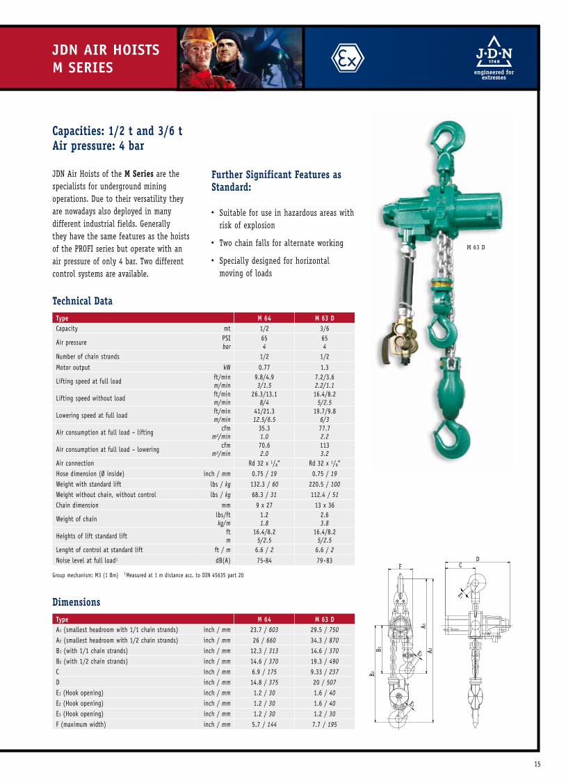
The trolley solution for restricted headroom areas.Capacities: 0.5 t up to 6.3 t
Standard features
Small number of maintenance/wear free moving parts
No additional motor lubrication required
2-step travelling speed
Adjustable trolley widths to suit your requirements
Special features
Able to negotiate curves
Extended trolley tie bars for bulky or elongated loads
Low Headroom Trolley LMF
*1s�t s�tep at F-control with 2-s�tep travelling s�peed, 1Meas�ured at 1m dis�tance acc. to DI�N 45�635� part 20
Hoist Type pROFi 05 Ti pROFi 1 Ti pROFi 2 Ti pROFi 3 Ti pROFi 6 TiTrolley Type LmF 05-2 t LmF 05-2 t LmF 05-2 t LmF 3.2 t LmF 6.3 tCapacity mt 0.5� 1 2 3.2 6.3
Air pres�s�ure PSI� bar
85� 6
85� 6
85� 6
85� 6
85� 6
Number of chain s�trands� 1 1 2 1 2Motor output Hois�t kW 1 1 1 3.5� 3.5�Motor output Trolley kW 0.2 0.2 0.2 0.2 0.2
Lifting s�peed at full load ft/min m/min
32.81 10
16.40 5
8.20 2.5
14.76 4.5
7.21 2.2
Lifting s�peed without load ft/min m/min
5�5�.77 17
32.81 10
16.40 5
29.5�2 9
14.76 4.5
Lowering s�peed at full load ft/min m/min
5�5�.77 17
36.09 11
18.04 5.5
35�.43 10.8
17.72 5.4
Travelling s�peed at full load ft/min m/min
29.5�3*/45�.93 9*/14
29.5�3*/45�.93 9*/14
29.5�3*/45�.93 9*/14
29.5�3*/45�.93 9*/14
29.5�3*/45�.93 9*/14
Air cons�umption at full load – lifting
cfm m3/min
42.38 1.2
42.38 1.2
42.38 1.2
141.26 4
141.26 4
Air cons�umption at full load – lowering
cfm m3/min
5�2.97 1.5
5�2.97 1.5
5�2.97 1.5
194.23 5.5
194.23 5.5
Air cons�umption trolley motor
cfm m3/min
21.19 0.6
21.19 0.6
21.19 0.6
21.19 0.6
21.19 0.6
Air connection G 1/2 G 1/2 G 1/2 G 3/4 G 3/4
Hos�e dimens�ion (Ø ins�ide) inch mm
1/2 13
1/2 13
1/2 13
3/4 19
3/4 19
Weight with s�tandard lift and control
lbs� kg
216.05� 98
218.26 99
231.5�9 105
462.97 210
727.5�3 330
Chain dimens�ion inch mm
0.28 x 0.83 7 x 21
0.28 x 0.83 7 x 21
0.28 x 0.83 7 x 21
0.5�1 x 1.42 13 x 36
0.5�1 x 1.42 13 x 36
Weight of chain lbs�/ft kg/m
0.67 1
0.67 1
0.67 1
2.6 3.8
2.6 3.8
Standard lift ft m
10 3
10 3
10 3
10 3
10 3
Length of control at s�tandard lift ft m
6.5� 2
6.5� 2
6.5� 2
6.5� 2
6.5� 2
Max. bottom flange thicknes�s� t
inch mm
0.98 25
0.98 25
0.98 25
1.38 35
1.38 35
Max. bottom flange width b inch mm
12.20 310
12.20 310
12.20 310
12.20 310
12.20 310
Min. bottom flange width b inch mm
3.15� 80
3.15� 80
3.15� 80
4.92 125
4.92 125
Nois�e level at full load1 – lifting dB(A) 75� 76 76 78 78Nois�e level at full load1 – lowering dB(A) 78 78 78 80 80
Technical Data
Where headroom is restricted and standard trolleys can’t meet the lifting height requirements we recommend JDN Low Headroom Trolleys whereby our air hoists are mounted horizontally. When only very low headroom is available we recommend JDN Ultra-Low Monorail Hoist design.
JDN LOW HEADROOm TROLLEys

22
JDN LOW HEADROOm TROLLEys
Hoist Type pROFi 05 Ti pROFi 1 Ti pROFi 2 Ti pROFi 3 Ti pROFi 6 TiTrolley Type LmF 05-2 t LmF 05-2 t LmF 05-2 t LmF 3.2 t LmF 6.3 t
A max. inch mm
4.13 105
4.13 105
4.13 105
4.13 105
4.17 106
B inch mm
1.42 36
1.42 36
1.42 36
1.42 36
2.76 70
b min. inch mm
3.15� 80
3.15� 80
3.15� 80
3.15� 80
4.92 125
C inch mm
6.46 164
6.46 164
6.46 164
6.46 164
6.65� 169
D1inch mm
2.76 70
2.76 70
2.76 70
2.76 70
6.5�0 165
D2inch mm
2.76 70
2.76 70
2.76 70
2.76 70
2.76 70
E1inch mm
4.5�7 116
4.5�7 116
4.5�7 116
4.5�7 116
9.29 236
E2inch mm
4.5�7 116
4.5�7 116
4.5�7 116
4.5�7 116
4.5�7 116
F inch mm
6.77 172
6.77 172
7.68 195
8.98 228
13.82 351
G1inch mm
3.74 95
3.74 95
3.74 95
3.74 95
7.76 197
G2inch mm
3.74 95
3.74 95
3.74 95
3.74 95
3.74 95
H min. inch mm
12.60 320
12.60 320
15�.5�1 394
16.34 415
21.14 537
J inch mm
12.60 320
12.60 320
12.60 320
15�.63 397
15�.63 397
K1inch mm
5�.71 145
5�.71 145
5�.71 145
9.17 233
9.17 233
K2inch mm
5�.98 152
5�.98 152
5�.98 152
9.76 248
9.76 248
L inch mm
28.15� 715
28.15� 715
28.15� 715
32.48 825
39.17 995
M inch mm
1.10 28
1.10 28
1.10 28
1.18 30
1.5�7 40
N inch mm
1.65� 42
1.65� 42
1.65� 42
1.65� 42
2.01 51
t max. inch mm
0.98 25
0.98 25
0.98 25
1.38 35
1.38 35
Dimensions
L
JG2 D2
E2
E1
D1 G1
H
F
M
A b + B C
b
N
K1 K2

23
BBH 1000 and BBH 2000
JDN Big Bag HandlingAir HoistsFor big bag handling J.D. Neuhaus offers innovative design solutions to meet the special requirements of these applications.
JDN Big Bag Handling Air Hoists are available in capacities of 1100 kg and 2200 kg with an air pressure of 6 bar.
Designs with one or two load hooks With one load hook for standard cruciform lifting beam designs. The extended distance between the hook and the chain box is particularly advantageous. This guarantees that there is no risk of collision between the load and the chain box.
With twin load hooks for more complex cruciform lifting beam designs or for standard lifting beam designs with two suspension points.
The advantages at a glance Particularly suited for use as big bag handling hoists and for the movement of all kinds of bulky loads due to the low headroom design.
Compact, modern design.
Suitable for use as a synchronised hoist in twin-hook design.
The use of JDN standard components guarantees reliable operation and cost effective manufacture.
No additional motor lubrication required.
Small number of maintenance/ wear free moving parts.
Chain box included as standard.
Suitable for a wide variety of beam sizes/profiles, with hook centres to suit your requirements.
Take advantage of the driving medium air: Suitable for use as standard in areas at
risk of explosion. Explosion protection classification according to Directive 94/9/EG (Equipment and Protective Systems Intended for use in Potentially Explosive Areas (ATEX)).
The hoists are available for the following explosion protection classifications:
II 2 GD IIA T4/II 3 GD IIB T4
II 2 GD IIB T4 or II 2 GD IIC T4.
100% duty rating, and thus no downtimes.
BBH 1000-2
JDN BiG BAG HANDLiNG AiR HOisTs

24
AC
Bb
t
X
NP
R
FG
H
J Y
Z
E
K
JDN BiG BAG HANDLiNG AiR HOisTs
DimensionsType BBH 1000-1 BBH 2000-1
A inch mm
13.1 332
B inch mm
6.4 163
8.7 220
bmin. inch
mm3.5�4 90
max. inch mm
12.20 310
C inch mm
7.17 182
E inch mm
7.68 195
F inch mm
3.7 95
G inch mm
6.3 159
H inch mm
15�.3 388
17.24 438
J inch mm
7.5�6 192
8.66 220
Kmin. inch
mm17.13 435
16.14 410
max. inch mm
43.31 1100
L inch mm
– –
M inch mm
1.10 28
N inch mm
9.84 250
P inch mm
2.76 70
R inch mm
4.5�7 116
t max. inch mm
1.18 30
Technical DataType BBH 1000-1 BBH 2000-1Capacity mt 1.1 2.2
Air pres�s�ure PSI� bar
85� 6
Number of hooks� 1Number of chain s�trands� 1 2Motor output hois�t kW 0.7Motor output trolley kW 0.2
Lifting s�peed at full load ft/min m/min
12.14 3.7
5�.5�8 1.7
Lifting s�peed without load ft/min m/min
24.61 7.5
11.48 3.5
Lowering s�peed at full load ft/min m/min
32.81 10
16.40 5
Air cons�umption at full load – lifting cfm m3/min
49.44 1.4
Air cons�umption at full load – lowering cfmm3/min
42.38 1.2
Air cons�umption at full load – trolley cfm m3/min
21.19 0.6
Air connection G 1/2
Hos�e dimens�ion (Ø ins�ide) inch mm
1/2 13
Weight at s�tandard lift and minimum k dimens�ion lbs� kg
286.60 130
302.03 137
Chain dimens�ion mm 7 x 21
Weight of chain lbs�/ft kg/m
0.67 1
Standard lift ft m
10 3
Length of control at s�tandard load – lift ft m
6.5� 2
Nois�e level at full load1 – lifting dB(A) 76Nois�e level at full load1 – lowering dB(A) 78Nois�e level at full load1 – trolley dB(A) 80
Group mechanis�m: M4 (1 Am) · 1 Meas�ured at 1 m dis�tance acc. to DI�N 45�635� part 20
25
Technical DataType BBH 1000-2 BBH 2000-2Capacity mt 1.1 2.2
Air pres�s�ure PSI� bar
85� 6
Number of hooks� 2Number of chain s�trands� 2 4Motor output hois�t kW 0.7Motor output trolley kW 0.2
Lifting s�peed at full load ft/min m/min
12.14 3.7
5�.5�8 1.7
Lifting s�peed without load ft/min m/min
24.61 7.5
11.48 3.5
Lowering s�peed at full load ft/min m/min
32.81 10
16.40 5
Air cons�umption at full load – lifting cfm m3/min
49.44 1.4
Air cons�umption at full load – lowering cfm m3/min
42.38 1.2
Air cons�umption at full load – trolley cfm m3/min
21.19 0.6
Air connection G 1/2
Hos�e dimens�ion (Ø ins�ide) inch mm
1/2 13
Weight at s�tandard lift and minimum k dimens�ion lbs� kg
302.03 137
328.49 149
Chain dimens�ion mm 7 x 21
Weight of chain lbs�/ft kg/m
0.67 1
Standard lift ft m
10 3
Length of control at s�tandard load – lift ft m
6.5� 2
Nois�e level at full load1 – lifting dB(A) 76Nois�e level at full load1 – lowering dB(A) 78Nois�e level at full load1 – trolley dB(A) 80
DimensionsType BBH 1000-2 BBH 2000-2
A inch mm
3.1 332
B inch mm
6.4 163
8.7 220
bmin. inch
mm3.5�4 90
max. inch mm
12.20 310
C inch mm
7.17 182
E inch mm
14.69 373
13.62 346
F inch mm
3.74 95
G inch mm
6.26 159
H inch mm
15�.3 388
17.24 438
J inch mm
7.5�6 192
8.66 220
Kmin. inch
mm10.24 260
max. inch mm
5�1.18 1300
L inch mm
6.89 175
5�.91 150
M inch mm
1.10 28
N inch mm
9.84 250
P inch mm
2.76 70
R inch mm
4.5�7 116
t max. inch mm
1.18 30
Group mechanis�m: M4 (1 Am) · 1 Meas�ured at 1 m dis�tance acc. to DI�N 45�635� part 20
NP
R
FG
H
J K L Y
M M
E
Z
AC
Bb
t
X
NP
R
FG
H
J Y
Z
E
K
26
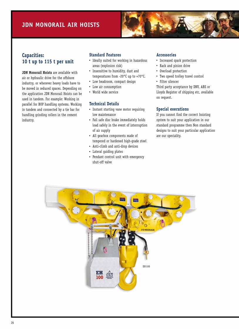
Capacities: 10 t up to 115 t per unit
JDN Monorail Hoists are available with air or hydraulic drive for the offshore industry, or wherever heavy loads have to be moved in reduced spaces. Depending on the application JDN Monorail Hoists can be used in tandem. For example: Working in parallel for BOP handling systems. Working in tandem and connected by a tie bar for handling grinding rollers in the cement industry.
Standard features Ideally suited for working in hazardous
areas (explosion risk) Insensitive to humidity, dust and
temperatures from -20°C up to +70°C. Low headroom, compact design Low air consumption World wide service
Technical Details Instant starting vane motor requiring
low maintenance Fail safe disc brake immediately holds
load safely in the event of interruption of air supply
All gearbox components made of tempered or hardened high-grade steel
Anti-climb and anti-drop devices Lateral guiding plates Pendant control unit with emergency
shut-off valve
Accessories Increased spark protection Rack and pinion drive Overload protection Two speed trolley travel control Filter silencer
Third party acceptance by DNV, ABS or Lloyds Register of shipping etc, available on request.
Special executionsIf you cannot find the correct hoisting system to suit your application in our standard programme then Non standard designs to suit your particular application are our speciality.
JDN mONORAiL AiR HOisTs
EH100

27
Type EH 10 EH 16 EH 20 EH 25 EH 30 EH 37 EH 40 EH 50 EH 60Capacity mt 10 16 20 25� 30 37.5� 40 5�0 60
Air pres�s�ure PSI� bar
85� 6
85� 6
85� 6
85� 6
85� 6
85� 6
85� 6
85� 6
85� 6
Number of chain s�trands� 2 3 4 2 2 3 3 4 4Motor output trolley kW 0.7 0.7 0.7 1.4 1.4 1.4 1.4 1.4 1.4Motor output hois�t kW 3.5� 3.5� 3.5� 6.3 6.3 6.3 6.3 6.3 6.3
Lifting s�peed at full load ft/m m/min
5�.3 1.6
3.3 1.0
2.3 0.7
4.1 1.25
3.3 1.0
2.5� 0.75
2.3 0.7
1.8 0.55
1.5� 0.45
Lifting s�peed without load ft/m m/min
10.5� 3.2
6.6 2.0
4.6 1.4
7.9 2.4
7.9 2.4
5�.6 1.7
5�.6 1.7
4.3 1.3
4.3 1.3
Lowering s�peed at full load ft/m m/min
11.2 3.4
6.9 2.1
5�.3 1.6
9.2 2.8
9.2 2.8
6.6 2.0
6.6 2.0
5�.3 1.6
5�.3 1.6
Travelling s�peed at full load ft/m m/min
39.4 12
39.4 12
39.4 12
39.4 12
39.4 12
39.4 12
39.4 12
39.4 12
39.4 12
Travelling s�peed without load ft/m m/min
44.3 13.5
44.3 13.5
44.3 13.5
44.3 13.5
44.3 13.5
44.3 13.5
44.3 13.5
44.3 13.5
44.3 13.5
Air cons�umption – trolley cfm m3/min
46 1.3
46 1.3
46 1.3
92 2.6
92 2.6
92 2.6
92 2.6
92 2.6
92 2.6
Air cons�umption – hois�t lifting cfm m3/min
141.5� 4
141.5� 4
141.5� 4
229.6 6.5
229.6 6.5
229.6 6.5
229.6 6.5
229.6 6.5
229.6 6.5
Air connection G 3/4 G 3/4 G 3/4 G 1 1/2 G 1 1/2 G 1 1/2 G 1 1/2 G 1 1/2 G 1 1/2
Hos�e dimens�ion(Ø ins�ide) inch mm
3/4 19
3/4 19
3/4 19
1 1/2 35
1 1/2 35
1 1/2 35
1 1/2 35
1 1/2 35
1 1/2 35
Weight with s�tandard lift lbs� kg
992.1 450
1267.7 575
1366.3 620
2205� 1000
2205� 1000
3307 1500
3307 1500
3638 1650
3638 1650
Chain dimens�ion mm 16 x 45� 16 x 45� 16 x 45� 23.5� x 66 23.5� x 66 23.5� x 66 23.5� x 66 23.5� x 66 23.5� x 66
Weight of chain lbs�/ft kg/m
3.9 5.8
3.9 5.8
3.9 5.8
3.9 12.2
8.2 12.2
8.2 12.2
8.2 12.2
8.2 12.2
8.2 12.2
Standard lift ft m
10 3
10 3
10 3
10 3
10 3
10 3
10 3
10 3
10 3
Length of control at s�tandard lift
ft m
6.5� 2
6.5� 2
6.5� 2
6.5� 2
6.5� 2
6.5� 2
6.5� 2
6.5� 2
6.5� 2
Nois�e level at full load1
with s�tandard s�ilencer – liftingdB(A) 78 78 80 78 78 78 78 78 78
Nois�e level at full load1 with s�tandard s�ilencer – lowering
dB(A) 80 80 84 82 82 82 82 82 82
Technical Data
1Meas�ured at 1m dis�tance acc. to DI�N 45�635� part 20, Group mechanis�m: EH10, EH16, EH20, EH25�, EH37, EH5�0: M3 (1 Bm), EH30, EH40, EH60: M2 (1 Cm)4 bar vers�ions� on reques�t
EH25EH20
28
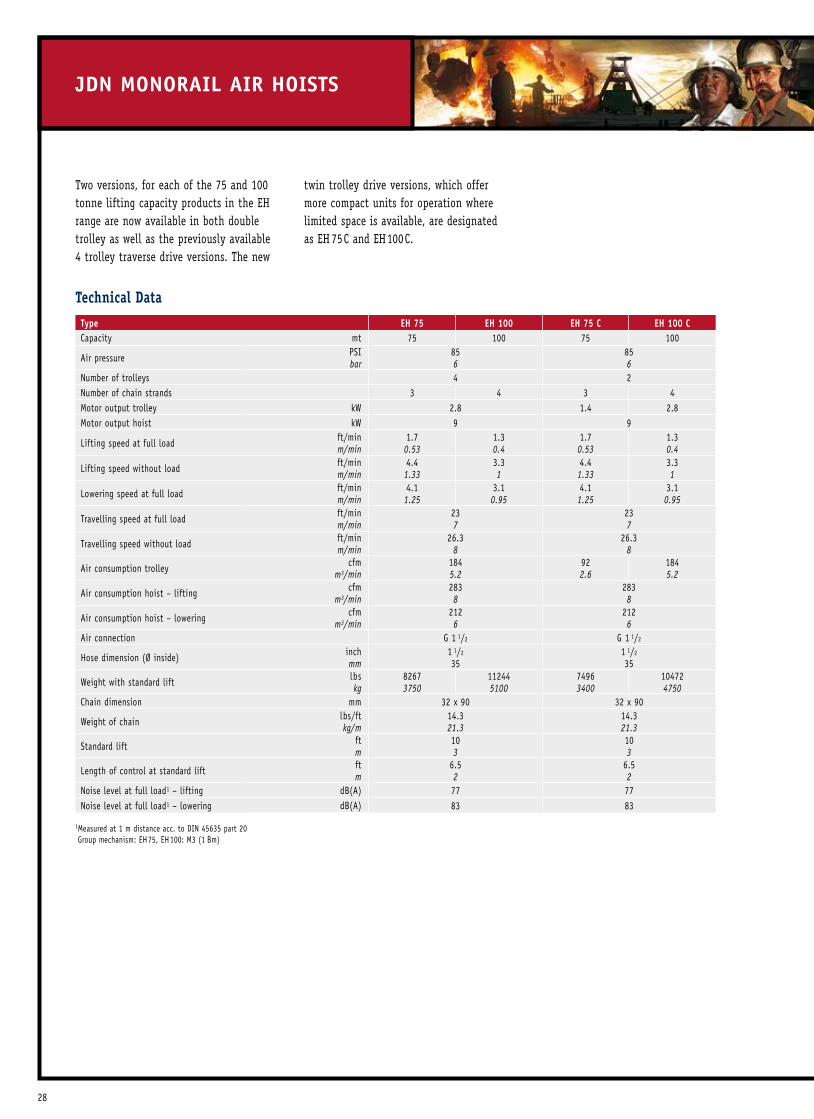
JDN mONORAiL AiR HOisTs
Technical DataType EH 75 EH 100 EH 75 C EH 100 CCapacity mt 75� 100 75� 100
Air pres�s�ure PSI� bar
85� 6
85� 6
Number of trolleys� 4 2Number of chain s�trands� 3 4 3 4Motor output trolley kW 2.8 1.4 2.8 Motor output hois�t kW 9 9
Lifting s�peed at full load ft/min m/min
1.7 0.53
1.3 0.4
1.7 0.53
1.3 0.4
Lifting s�peed without load ft/min m/min
4.4 1.33
3.3 1
4.4 1.33
3.3 1
Lowering s�peed at full load ft/min m/min
4.1 1.25
3.1 0.95
4.1 1.25
3.1 0.95
Travelling s�peed at full load ft/min m/min
23 7
23 7
Travelling s�peed without load ft/min m/min
26.3 8
26.3 8
Air cons�umption trolley cfm m3/min
184 5.2
92 2.6
184 5.2
Air cons�umption hois�t – lifting cfm m3/min
283 8
283 8
Air cons�umption hois�t – lowering cfm m3/min
212 6
212 6
Air connection G 1 1/2 G 1 1/2
Hos�e dimens�ion (Ø ins�ide) inch mm
1 1/2
35�1 1/2
35�
Weight with s�tandard lift lbs� kg
8267 3750
11244 5100
7496 3400
10472 4750
Chain dimens�ion mm 32 x 90 32 x 90
Weight of chain lbs�/ft kg/m
14.3 21.3
14.3 21.3
Standard lift ft m
10 3
10 3
Length of control at s�tandard lift ft m
6.5� 2
6.5� 2
Nois�e level at full load1 – lifting dB(A) 77 77Nois�e level at full load1 – lowering dB(A) 83 83
1 Meas�ured at 1 m dis�tance acc. to DI�N 45�635� part 20 Group mechanis�m: EH75�, EH100: M3 (1 Bm)
twin trolley drive versions, which offer more compact units for operation where limited space is available, are designated as EH 75C and EH100C.
Two versions, for each of the 75 and 100 tonne lifting capacity products in the EH range are now available in both double trolley as well as the previously available 4 trolley traverse drive versions. The new

29
b
b + BA C
GML
D
b
b + B CA
ML
G
D
Type EH 10 EH 16 EH 20 EH 25 EH 30 EH 37 EH 40 EH 50 EH 60 EH 75 EH 100 EH 75 C EH 100 C
A inch mm
4.1 105
5�.1 130
5�.1 130
3.5�-6.81 90-1721
4.9 125
4.9 125
3.9 100
4.9 125
4.9 125
6.9 176
B inch mm
2.8 70
2.7 68
2.7 68
2.8 70
2.8 70
2.7 68
2.7 68
2.7 68
2.7 68
2.7 68
2.7 68
2.7 68
2.7 68
C inch mm
11.2 285
11.6 295
11.6 295
11.6 295
11.6 295
11.6 295
11.6 295
11.8 300
11.8 300
11.6 295
11.8 300
11.8 300
12.6 320
D inch mm
0.9 25
1.4 35
1.4 35
0.9 25
1.4 35
1.4 35
1.4 35
1.6 40
1.6 40
1.4 35
1.6 40
1.6 40
2.4 60
E inch mm
7.8 198
8.7 220
8.7 220
7.4 188
7.4 188
8.6 218
8.6 218
11.1 283
11.1 283
8.6 218
11.1 282
11.1 282
15� 382
F* inch mm
27.8 705
29.5� 750
32.3 820
39.3 998
39.3 998
43.0 1090
43.0 1090
44.9 1140
44.9 1140
5�9.2 1500
5�9.2 1500
5�9.2 1500
5�9.2 1500
G inch mm
5�.4 138
8.4 213
7.9 200
6.7 170
6.7 170
12.6 320
12.6 320
16.5� 420
16.5� 420
18.9 480
22.6 575
18.9 480
22.6 575
H inch mm
1.7 44
2 53
2.8 70
2.8 70
2.8 70
3.9 100
3.9 100
3.9 100
3.9 100
4.7 120
4.7 120
4.7 120
4.7 120
J inch mm
7.6 192
7.3 185
10.5� 266
13.8 350
13.8 350
13.0 330
13.0 330
13.4 340
13.4 340
17.9 455
18.5� 470
17.9 455
18.5� 470
K inch mm
22.8 580
23.6 600
23.6 600
43.3 1100
43.3 1100
5�5�.1 1400
5�5�.1 1400
61.0 1550
61.0 1550
118.9 3020
124.8 3170
68.90 1750
75�.98 1930
L inch mm
12.1 308
14.5� 367
14.5� 367
17.7 450
17.7 450
21.3 540
21.3 540
21.3 540
21.3 540
32.5� 825
32.5� 825
32.5� 825
32.5� 825
M inch mm
10.5� 266
12.8 325
12.8 325
17.7 450
17.7 450
21.3 540
21.3 540
21.3 540
21.3 540
27.8 706
27.8 706
23.4 670
27.8 706
Dimensions
1Depending on beam width*Chain containers� increas�e the hois�t headroom

30
JDN ULTRA-LOW mONORAiL HOisTs
1Meas�ured at 1m dis�tance acc. to DI�N 45�635� part 20Group mechanis�m: M3 (1 Bm)Technical data for higher capacities� on reques�t.
Type UH 4 UH 6 UH 8 UH 12 UH 16Capacity mt 4 6 8 12 16
Air pres�s�ure PSI� bar
85� 6
85� 6
85� 6
85� 6
85� 6
Number of chain s�trands� 2 2 4 4 4Motor output kW 2.5� 2.5� 2.5� 2.5� 2.5�
Lifting s�peed at full load ft/min m/min
9.84 3.0
6.5�6 2.0
4.5�9 1.4
2.95� 0.9
2.13 0.65
Lifting s�peed without load ft/min m/min
19.69 6.0
14.76 4.5
9.5�1 2.9
7.22 2.2
3.94 1.2
Lowering s�peed at full load ft/min m/min
24.61 7.5
17.06 5.2
11.81 3.6
8.20 2.5
4.92 1.5
Air cons�umption at full load – lifting
cfm m3/min
141.26 4.0
141.26 4.0
141.26 4.0
141.26 4.0
141.26 4.0
Air cons�umption at full load – lowering
cfm m3/min
194.23 5.5
194.23 5.5
194.23 5.5
194.23 5.5
194.23 5.5
Air connection G 3/4 G 3/4 G 3/4 G 3/4 G 3/4
Hos�e dimens�ion (Ø ins�ide) inch mm
3/4 19
3/4 19
3/4 19
3/4 19
3/4 19
Weight with s�tandard lift lbs� kg
1014.13 460
1036.17 470
1190.5�0 540
1212.5�4 550
1234.60 560
Chain dimens�ion mm 13 x 36 13 x 36 13 x 36 13 x 36 13 x 36
Weight of chain lbs�/ft kg/m
2.6 3.8
2.6 3.8
2.6 3.8
2.6 3.8
2.6 3.8
Standard lift ft m
10 3
10 3
10 3
10 3
10 3
Length of control at s�tandard lift
ft m
6.5� 2
6.5� 2
6.5� 2
6.5� 2
6.5� 2
Nois�e level at full load1 – lifting
dB(A) 78 78 78 78 78
Nois�e level at full load1 – lowering
dB(A) 80 80 80 80 80
Technical Data
Capacities: 4 t up to 100 tAir pressure: 6 bar
Where loads have to be lifted and transpor-ted in extremely reduced spaces the JDN Ultra-Low Monorail Hoists provide the ideal solution. For example the Ultra-Low Monorail Hoist with a load capacity of 6 t has a headroom of only 230 mm. Standard features
Ideally suited for working in hazardous areas (explosion risk)
Insensitive to humidity, dust and temperatures from -20°C up to +70°C
Extremely low headroom
Low air consumption
Available with increased spark protection
UH 100

31
Dimens�ions� for higher capacities� on reques�t.
Type UH 4 UH 6 UH 8 UH 12 UH 16
A inch mm
7.68 195
12.01 305
7.68 195
12.01 305
12.01 305
B inch mm
7.87 200
7.87 200
7.87 200
7.87 200
7.87 200
C inch mm
11.16 284
11.16 284
11.16 284
11.16 284
11.16 284
D inch mm
6.5�0 165
6.5�0 165
6.5�0 165
6.5�0 165
6.5�0 165
E inch mm
9.29 236
9.29 236
9.29 236
9.29 236
9.29 236
F inch mm
12.99 330
12.99 330
11.14 283
11.14 283
11.14 283
G inch mm
7.78 197.5
7.78 197.5
7.78 197.5
7.78 197.5
7.78 197.5
H min. 15�0 < = b < = 310 inch mm
9.06 230
9.06 230
– –
– –
– –
H min. 15�0 < = b < = 230 inch mm
– –
– –
11.61 295
11.61 295
13.15� 334
H min. 230 < = b < = 310 inch mm
– –
– –
10.87 276
10.87 276
12.40 315
J inch mm
15�.75� 400
15�.75� 400
15�.75� 400
15�.75� 400
15�.75� 400
K inch mm
21.06 535
21.06 535
21.06 535
21.06 535
21.06 535
L inch mm
39.37 1000
39.37 1000
39.37 1000
39.37 1000
39.37 1000
M inch mm
1.5�7 40
1.5�7 40
1.73 44
1.73 44
2.09 53
N inch mm
2.01 51
2.01 51
2.60 66
2.60 66
3.23 82
Dimensions
L
E
D
K
H
J
G
FM
t max
=40
A b + B
B
C
N

32
JDN BOp HANDLiNG sysTEms
BOP handling systems from J.D. Neuhaus are recognised for their reliable, robust and efficient operation on land and on jack-up and semi-submersible drilling platforms. The monorail air hoists (EH) in our BOP handling systems feature a compact design with low installation height. They can be used as double hoists in standard BOP
handling systems or, when linked together with a coupling rod, can be operated as a 4-point BOP handling system. For extremely low headrooms we recommend our ultra-low hoists from the UH series. Alternatively, all BOP handling systems are available with hydraulic drives.
options
Offshore version for special corrosion protection under tough weather condi-tions (salty, moist air) on sea and land
Offshore paint finish
Rack and pinion drive
Delta-P overload protection
Ultra-low hoists
Pneumatic, hydraulic or electric remote control
Load display systems
Radio remote control
Articulated trolleys for limited side pulling
Individual acceptance by the authorised companies of your choice
Special versions according to your requirements
Cryogenic versions down to -45°C
Technical Data
For further technical data s�ee JDN monorail hois�ts�
Type BH 20 BH 32 BH 40 BH 50 BH 75 BH 100 BH 150 BH 200Cons�is�ting of 2 units� EH 10 EH 16 EH 20 EH 25� EH 37 EH 5�0 EH 75� EH 100Capacity mt 20 32 40 5�0 75� 100 15�0 200
Weight with s�tandard lift lbs� kg
1984 900
25�35� 1150
2734 1240
4409 2000
6614 3000
7275� 3300
17637 8000
25�133 11400
Standard lift ft m
10 3
10 3
10 3
10 3
10 3
10 3
10 3
10 3
Length of control at s�tandard lift
ft m
6.5� 2
6.5� 2
6.5� 2
6.5� 2
6.5� 2
6.5� 2
6.5� 2
6.5� 2
Capacities: 20 t up to 200 t
Ultra Low Headroom BOP Handling System BHU 200

33
JDN Cryogenic Hoists
JDN Subsea Hoists
The ultimate tool for every professional diver
The JDN PROFI Subsea series is available with air or hydraulic drives. As well as a sensitive control system, the PROFI hoists are equipped with an overload protection. PROFI subsea hoists are a versatile and indispensable tool for professional divers and are suitable for horizontal work as well as for oblique pulling.
Advantages Air or hydraulic drive
Infinitely variable speeds can be regulated sensitively
With overload protection
Very versatile, also suitable for horizontal and oblique pulling thanks to hook suspension
Not only suitable for BoP handling in arctic areas:
The temperature range of standard JDN hoists is -20°C to +70°C. JDN has develo-ped hydraulic hoists for applications at temperatures as low as minus 45°C, such as BOP handling in arctic areas. To enable these hydraulic drives to be used under such extreme temperatures, they are fitted with a device that pre-heats the drives to a temperature of -25°C before being opera-ted. This is achieved directly by means of the standard hydraulic supply. JDN hydrau-lic hoists are designed to be operated with low-temperature hydraulic fluids and can be operated efficiently at temperatures from -45°C to +40°C.
Advantages
Application range -45°C to +40°C
Hydraulic drive
Easy starting thanks to pre-heating device for the drives
Operation with low-temperature hydraulic fluid
Tested under real conditions and in use in Siberia
PROFI 6TI Subsea
EH 20-H
Do you need a hoist for toughest conditions? Then contact us.
JDN HOisTs FOR UsE iN THE TOUGHEsT CONDiTiONs

34
JDN HyDRAULiC HOisTs AND mONORAiL HOisTs
JDN Hydraulic Hoists and Hydraulic Monorail Hoists are available with capa- cities from 3 t up to 100 t. Depending on motor size these hoists work with an intake pressure of 130 bar up to 180 bar. Pressure fluid: Oil.
Advantages
Ideally suited for working in hazardous areas (explosion risk)
Extremely low noise emissions
Fully enclosed highly robust gear motor
Integrated overload protection
Only two supply connections at hoist ”P” and ”T”, leakage oil drained internally
The drive is hermetically sealed off from the environment
Hydraulic Hoists Profi / Hydraulic Monorail Hoists Capacities: 3 t up to 100 t
PROFI 6TI-H

35
Type 3 Ti-H 6 Ti-H 10 Ti-H 16 Ti-H 20 Ti-HCapacity mt 3.2 6.3 10 16 20
I�ntake pres�s�ure PSI� bar
1885� 130
1885� 130
1885� 130
1885� 130
1885� 130
I�ntake volume cfm l/min
1.7 48
1.7 48
1.7 48
1.7 48
1.7 48
Number of chain s�trands� 1 2 2 3 4Motor output kW 3.5� 3.5� 3.5� 3.5� 3.5�Motortype KM 1/16 KM 1/16 KM 1/16 KM 1/16 KM 1/16
Lifting s�peed at full load ft/min m/min
13.1 4.0
6.6 2.0
3.9 1.2
2.6 0.8
2.0 0.6
Lifting s�peed without load ft/min m/min
14.8 4.5
7.6 2.3
4.1 1.25
2.7 0.82
2.0 0.6
Lowering s�peed at full load ft/min m/min
14.8 4.5
7.6 2.3
4.3 1.3
2.8 0.85
2.1 0.65
Lowering s�peed without load ft/min m/min
14.8 4.5
7.6 2.3
4.3 1.3
2.8 0.85
2.1 0.65
Connection G 1/2 G 1/2 G 1/2 G 1/2 G 1/2
Hos�e dimens�ion DN 12 DN 12 DN 12 DN 12 DN 12Weight at s�tandard lift with control
lbs� kg
198.4 90
25�1.3 114
35�2.7 160
5�38.0 244
637.1 289
Chain dimens�ion mm 13 x 36 13 x 36 16 x 45� 16 x 45� 16 x 45�
Weight of chain lbs�/ft kg/m
2.6 3.8
2.6 3.8
3.9 5.8
3.9 5.8
3.9 5.8
Standard lift ft m
10 3
10 3
10 3
10 3
10 3
Length of control at s�tandard lift
ft m
6.5� 2
6.5� 2
6.5� 2
6.5� 2
6.5� 2
Technical Data
Group mechanis�m: M3 (1 Bm)
Type 3 Ti-H 6 Ti-H 10 Ti-H 16 Ti-H 20 Ti-HA s�malles�t headroom1 inch / mm 23.4 / 593 26.5� / 674 32 / 813 35�.4 / 898 40.6 / 1030B inch / mm 14.7 / 373 17.9 / 454 21.6 / 548 23.5� / 598 26.4 / 670C inch / mm 9.2 / 233 9.2 / 233 12.2 / 308 15� / 382 15� / 382D inch / mm 22.8 / 578 22.8 / 578 26.4 / 670 31 / 787 31 / 787E1 inch / mm 1.6 / 40 1.6 / 40 1.8 / 44 2.1 / 53 2.8 / 70E2 inch / mm 1.2 / 30 1.6 / 40 1.8 / 44 2.1 / 53 2.8 / 70F inch / mm 7.4 / 187 6.1 / 154 7.8 / 197 7.8 / 199 7.1 / 180
Dimensions
1 Chain containers� increas�e the hois�t headroom G
E1
B
A
F
E2
D
C
Hydraulic Hoists Profi 3Ti-H - 20Ti-H

36
JDN HyDRAULiC HOisTs AND mONORAiL HOisTs
Type 25 Ti-H 37 Ti-H 50 Ti-H 75 Ti-H 100 Ti-HCapacity mt 25� 37.5� 5�0 75� 100
I�ntake pres�s�ure PSI� bar
2176 150
2176 150
2176 150
2611 180
2611 180
I�ntake volume cfm l/min
2.8 80
2.8 80
2.8 80
3.0 85
3.0 85
Number of chain s�trands� 2 3 4 3 4Motor output kW 6 6 6 9 9Motor type KM 2/32 KM 2/32 KM2/32 KM2/32 KM2/32
Lifting s�peed at full load ft/min m/min
3.6 1.1
2.3 0.7
1.6 0.5
1.7 0.53
1.3 0.4
Lifting s�peed without load ft/min m/min
3.9 1.2
2.6 0.8
1.6 0.5
2.0 0.6
1.5� 0.45
Lowering s�peed at full load ft/min m/min
3.9 1.2
2.6 0.8
1.6 0.5
2.0 0.6
1.5� 0.45
Lowering s�peed without load ft/min m/min
3.9 1.2
2.6 0.8
1.6 0.5
2.0 0.6
1.5� 0.45
Connection G 3/4 G 3/4 G 3/4 G 3/4 G 3/4
Hos�e dimens�ion DN 16 DN 16 DN 16 DN 16 DN 16Weight with s�tandard lift and control
lbs� kg
1282 583
2123 965
2068 940
4079 1850
45�19 2050
Chain dimens�ion mm 23.5� x 66 23.5� x 66 23.5� x 66 32 x 90 32 x 90
Weight of chain lbs�/ft kg/m
8.2 12.2
8.2 12.2
8.2 12.2
14.3 21.3
14.3 21.3
Standard lift ft m
10 3
10 3
10 3
10 3
10 3
Length of control with s�tandard lift ft m
6.5� 2
6.5� 2
6.5� 2
6.5� 2
6.5� 2
Technical Data
Group mechanis�m: PROFI� 25�TI�-H – PROFI� 100TI�-H M3 (1 Bm)
Type 25 Ti-H 37 Ti-H 50 Ti-H 75 Ti-H 100 Ti-H
A s�malles�t headroom1 inch mm
5�0.5� 1282
5�7.7 1466
66.9 1700
76.0 1930
76.0 1930
B inch mm
37.3 948
36.8 935
45� 1144
49.2 1250
49.2 1250
C inch mm
15�.5� 393
14.8 377
17.4 442
32.5� 825
32.5� 825
D inch mm
42.1 1069
40.8 1037
48.6 1235
64.4 1635
64.4 1635
E1inch mm
2.8 70
3.9 100
3.9 100
4.7 120
4.7 120
E2inch mm
2.8 70
3.9 100
3.9 100
4.7 120
4.7 120
F inch mm
18.4 466
20.4 518
12.2 310
15�.9 405�
14.4 365
G inch mm
24 610
29.3 745
21.2 539
23.6 600
23.6 600
Dimensions
1 Chain containers� increas�e the hois�t headroom
Hydraulic Hoists Profi 25Ti-H – 100Ti-H
G
E1
E2
B A
F
D
C

37
Type EH 20-H EH 25-H EH 37-H EH 50-H EH 75-H EH 100-HCapacity mt 20 25� 37.5� 5�0 75� 100
I�ntake pres�s�ure PSI� bar
1885� 130
2176 150
2176 150
2176 150
2611 180
2611 180
I�ntake volume cfm l/min
1.7 48
2.8 80
2.8 80
2.8 80
3 85
3 85
Number of chain s�trands� 4 2 3 4 3 4Motor output – Trolley kW 0.7 1.4 1.4 1.4 2.8 2.8Motor output – Hois�t kW 3.5� 6 6 6 9 9Motor type – Trolley KM1/8 KM1/8 KM1/8 KM1/8 KM1/8 KM1/8Motor type – Hois�t KM1/16 KM2/32 KM2/32 KM2/32 KM2/32 KM2/32
Lifting s�peed at full load ft/min m/min
2.0 0.6
3.6 1.1
2.3 0.7
1.6 0.5
1.7 0.53
1.3 0.4
Lifting s�peed without load ft/min m/min
2.0 0.6
3.9 1.2
2.6 0.8
2 0.6
2 0.6
1.5� 0.45
Lowering s�peed at full load ft/min m/min
2.1 0.65
3.9 1.2
2.6 0.8
2 0.6
2 0.6
1.5� 0.45
Lowering s�peed without load
ft/min m/min
2.1 0.65
3.9 1.2
2.6 0.8
2 0.6
2 0.6
1.5� 0.45
Travelling s�peed at full load
ft/min m/min
39.4 12
39.4 12
39.4 12
39.4 12
39.4 12
39.4 12
Connection G 1/2 G 3/4 G 3/4 G 3/4 G 3/4 G 3/4
Hos�e dimens�ion DN 12 DN 16 DN 16 DN 16 DN 16 DN 16Weight with s�tandard lift and control
lbs� kg
15�84 720
2310 1050
3410 1550
4136 1880
8378 3800
1135�4 5150
Chain dimens�ion mm 16 x 45� 23.5� x 66 23.5� x 66 23.5� x 66 32 x 90 32 x 90
Weight of chain lbs�/ft kg/m
3.9 5.8
8.2 12.2
8.2 12.2
8.2 12.2
14.3 21.3
14.3 21.3
Standard lift ft m
10 3
10 3
10 3
10 3
10 3
10 3
Length of control with s�tandard lift
ft m
6.5� 2
6.5� 2
6.5� 2
6.5� 2
6.5� 2
6.5� 2
Technical Data
Group mechanis�m: EH 20-H – EH 100-H M3 (1 Bm)
Hydraulic Monorail Hoists EH 20-H – EH 100-H
Type EH 20-H EH 25-H EH 37-H EH 50-H EH 75-H EH 100-H
A inch mm
5�.1 130
5�.8 146
5�.8 146
4.9 125
3.9 100
4.9 125
B inch mm
2.7 68
2.8 70
2.8 70
2.7 68
2.7 68
2.7 68
C inch mm
10.5� 267
10.1 257
10.5� 267
10.7 272
8.9 225
9.1 230
D inch mm
1.4 35
1 25
1 25
1.6 40
1.4 35
1.6 40
E inch mm
8.7 220
7.8 198
8.7 220
11.1 283
8.6 218
11.1 282
F1 inch mm
32.3 820
39.3 998
42.1 1070
45�.3 1150
5�9.1 1500
5�9.1 1500
G inch mm
7.9 200
6.7 170
7.5� 190
16.5� 420
18.9 480
22.6 575
H inch mm
2.8 70
2.8 70
3.9 100
3.9 100
4.7 120
4.7 120
J inch mm
10.5� 266
13.8 350
17.9 455
13.4 340
17.9 455
18.5� 470
K inch mm
23.6 600
46.7 1185
68.1 1730
66.1 1680
118.9 3020
124.8 3170
L inch mm
14.5� 367
14.8 377
14.8 377
18.2 462
32.5� 825
32.5� 825
M inch mm
16.5� 420
22.1 562
22.1 562
27.0 687
31.7 805
31.7 805
Dimensions
1Chain containers� increas�e the hois�t headroom
EH 20-H
EH 25-H
A b + B C
D b
G
L M
K
J
FE
H

38
JDN CRANE sysTEms/CRANE KiTs
Explosion-protected JDN Crane Systems are the right choice for the most challen-ging environmental conditions, whether onshore or offshore. Available in air drive or hydraulic drive versions.
The delivery programme comprises explosion-proof
Top running overhead travelling cranes
Under hung overhead travelling cranes
Jib cranes
which can be designed to your individual needs, customised installations are our speciality. Depending on your requirements JDN air hoists in motor trolleys or monorail hoist systems are integrated into the crane design. An ergonomically designed pneu-matic pendant control is supplied with two speed control as standard for crane and trolley travel. Infinitely variable hoist and trolley speed control is also available.
Different JDN Cranes in Detail
Overhead cranes with single or double girder design
Underhung cranes including low headroom design
Jib cranes
Cranes with in line mechanically linked synchronised hoists
Cranes with parallel operating hoists
Capacities up to 100 t
Crane spans up to 36 m
Capacities: up to 10 t
J.D. Neuhaus can offer crane manufacturers crane component kits complete with pneu-matic crane drives. With these crane kits overhead travelling cranes up to 10 t capa-city can be built very simply and economi-cally, especially for applications in hazar-dous areas.
The crane manufacturer provides the main girder and JDN delivers all the components that are necessary to build an air powered crane of their chosen design:
End carriages with pneumatic drives Energy feeding systems Safety accessories And of course the appropriate air hoist with trolley
JDN Crane Kits for explosion-proof air cranes
Technical data
x = Standard + = Option (s�peeds� under s�tandard conditions�)
Capacity main travel (crane) Cross travel (trolley) Hoist
max. s�peed control max. s�peed control max. s�peed control
[m/min] 2-s�teps� [m/min] 2-s�teps� variable[m/min]
lifting/lowering1-s�tep variable
1 t 7/20 x 9/14 x 5�/12 x +2 t 7/20 x 9/14 x 2.5�/6 x +3 t 7/20 x 9/14 x 3.5�/8.5� x +6 t 10/24 x 9/14 x 1.5�/3.5� x +10 t 7/20 x 5�/12 x 1.0/3.0 x +15� t 5�/25� x 5�/12 x + 0.7/1.5� x +20 t 5�/25� x 5�/12 x + 0.5�/1.3 x +32 t 5�/25� x 5�/12 x + 0.6/1.3 x40 t 5�/25� x 5�/12 x + 0.65�/1.2 x5�0 t 5�/25� x 5�/12 x + 0.5�0/1.1 x

39
Filter s�ilencer
Filter regulator
Service unit
Main air emergency-stop valve
Chain box
Special grease cartridge for oil-free operation, volume 250 ml
Limit switch for lifting and travelling
Booster valve (control lengths over 12 m)
Extension arm for control on motorised trolley
Additional suspension for chain box (for installation in trolley)
Copper-plated load hook for increased spark protection
Stainless steel load hook (up to 750 kg capacity)
Stainless steel chain (reduced capacity) up to 6TI
Manual emergency lowering device for PROFI 3TI – 20TI hoists
Special paint finishes
We offer a wide range of accessories desi-gned to ensure that JDN standard products are suitable for your specific applications. This means, for example, that you can meet very specific safety requirements, adjust performance capacity or make ope-rations even more convenient.
Hoists and cranes from J.D. Neuhaus have an unbeatable advantage over electrically-driven lifting equipment: Even the stan-dard versions are suitable for use in explosion-hazardous areas and bear explosion-proof labelling according to the ATEX standard.
If you have any questions about the topic of explosion protection, please contact our sales team. We will be happy to advise you.
EX ii 2 GD iiB T4
ATEX mandatory mar-king for equipment usable in explosive atmospheres
ii surface Work
2For use in zone 1
GGas
I�I�C(Acetylene & Hydrogen)
Temperature Clas�s�
I�Underground Work
3For us�e in zone 2
DDust
iiB(Ethylene)
I�I�A(Propane)
Example: EX ii 2 GD iiB T4 classification means:
JDN Accessories Tailored to your individual needs
JDN Explosion Protection Classification and marking
T1 < = 45�0°C T2 < = 300°C T3 < = 200°C T4 < = 135°C T5� < = 100°C T6 < = 85�°C
JDN EXpLOsiON pROTECTiONJDN ACCEssORiEs

40
JDN CONTROLs
JDN Air Hoists and Cranes are available with various controls to suit your special necessities.
Suitable for any control length:This control type provides infinitely speed control for hoist lifting and lowering motions and is suitable for any required control length. The rope control option is available for all PROFI series hoists up to 25 t capacity. For larger capacity PROFI series hoists 37 TI, 50 TI and 100 TI the rope is replaced by a pull chain for greater strength.
rope Control
Sensitive control, for easy handling:The FI-Control provides precise infinitely variable speed control and the ergonomically designed synthetic housing ensures com- fortable handling for the operator. The use of corrosion resistant materials makes it suitable for use in aggressive atmospheres, with the control hoses enclosed in an outer sheath which protects them from external conditions.
fi-Control
Low maintenance, corrosion-proof:The very robust brass construction distinguishes the E-type pen-dant control valve. Low weight and ergonomic design ensure ease of handling. Only available in single speed control version.
E-Control

41
Controls for JDN Air Hoists in motor trolleyand JDN Monorail Hoists
For controlling JDN air hoists in motor trolleys and JDN monorail hoists we recommend the four button version of the E or F-control. The rope control option is also available.
Controls for JDN Air Cranes
For controlling JDN air cranes the F-control is the most suitable because of it‘s multi-function capability.
operating Convenience via radio control
To overcome excessive distances between operator and crane, or to use hoisting equipment in remote areas, the JDN Radio Control offers a convenient and safe alternative to other control types. The JDN radio control is also available in explosion-proof design.
Available for multi-function use:The F-control is manufactured from an unbreakable synthetic mate-rial, resistant to external conditions. The ergonomically designed housing ensures ease of handling. Up to 18 different control func-tions can be incorporated in a single pendant control e.g key switch, two stage travelling speed, klaxon or simultaneous control of two hoist motors. As an option the F-control can also be deli-vered with infinitely variable speed control of hoisting and trolley travelling motions.
f-Control

42
JDN ENERGy sUppLiEs
A series of supply systems are available for powering JDN Air Hoists in trolleys, monorail hoists and crane systems:
Hose trolleys
The hose is fastened to trolleys, which roll directly on the bottom flange of the beam. With each horizontal move of the hoist along the beam, the hose trolleys make the hose follow suit. The hose trolleys will be used for short distances or if there is not enough space on the side of the beam to install C or square bars. Your advantages: Easy to install Cost-efficient
Consisting of: Hose carriages and hose
Spiral hose
This simple and economical solution is suitable for distances of up to 10 metres. The hose rings are suspended on a plastic-coated rope that runs parallel to the track.
The spiral hose can be used in category 3 (zone 2) with gases in explosion group IIA and IIB. It is not suitable for applications in category 2 (zone 1) or group IIC.
Practical tip: Make sure to lay the hose so that its extended length is roughly 1.5 times the required distance.
Consisting of: Tensioning arms, rope tensioners, hose and rope
Main air connection
Main air connection
Hose trolleys Spiral hose Square bar or C rail Energy chain

43
Square bar & C rail
Galvanised C rails or square bars are installed along the beam to carry the energy supply lines.
Square barDepending on the local conditions, rails and curved tracks of different lengths are available, as well as an extensive range of installation accessories. The square bar is also suitable for curved tracks.
Consisting of: Square bars, tensioning arms, hose, hose supports and supply line carriages
C rail Consisting of: C rails with support,
adapter, antistatic supply hose and hose support. The supports must be attached to the upper flange of the beam.
Detail A Detail B
Main air connection
A B
Detail A Detail B
Main air connection
A B

44
JDN ENERGy sUppLiEs
Energy chain
Energy chain for trolley drive of overhead travelling cranesThe energy supply for trolley drive in overhead travelling cranes is realised bya horizontal version of the energy chain. A guide channel is mounted on thegirder with the chain gliding inside. Air distribution and the control box are also attached to the guide channel. Usually there are two different types ofhoses inside the energy chain: The air hose, which feeds the hoisting motorand the trolley motor, and the control hose for crane control functions.
In case of low headroom requirements choose vertical installed energy chain,like the supply for trolleys in underslung cranes.
Energy chain for crane drive of overhead travelling cranesThe energy supply for crane drive in over-head travelling cranes is realised by avertical installation of the energy chain. The necessary guide channel system ismounted with clamped brackets on the bottom flange. If different profile sizesfor the bottom flange are used because varying in support spacing, the bracketsmay be clamped to the top flange. The clamped brackets can be used for all thenormal steel girder sections (with flange thickness 7-40 mm (0,28-1,57 inch)). The energy chain carries air hoses inside, which supply the hoisting motor, driving motors as well as the control hoses of the crane. In addition it is possible to install further control hoses and electric cables inside the energy chain. The main air connection of the energy supply is located midway of the cranetravel distance.
Energy chain for trolley and crane drive of underslung cranesThe energy supply for hoists with trolley and for crane drives in underslung cranes is realised by a vertical installation of the energy chain. The guide channel system is mounted with c-consoles, which are clamped by claws on the top flange of the girder. The dimensions of the c-consoles are depending on the used girder.
Supply air hoses for hoisting and travelling as well as control hoses are installed in the energy chain.
Energy chain crane drive (vertical version)
Energy chain trolley drive (horizontal version)
Energy s�upply at an overhead travelling crane

45
JDN sERviCE
More safety for you, around the world
JDN Global Service
Maximum operating safety results in ensured productivity: That’s our promise for your JDN products and systems. As a J.D. Neuhaus hoist or crane system operator, you know thanks to your own experience that our products are exemplary when it comes to reliability and longevity.
Maximise the potential of longevity
Is it possible to increase the profitability of an investment and simultaneously reduce the risk of production downtime? Yes, it is! By carefully planning ahead. With JDN Service at your side, you ensure the continuous operational availability of your JDN hoists. And: With regular main-tenance, you simultaneously ensure the maximum longevity of your JDN products.
Benefit from the advantages of the manufacturer
Long downtimes and a lack of operational safety of a system are absolutely the worst case scenario for every conscientious manager. Your best defence in this case is a service partnership with J.D. Neuhaus, since nobody knows JDN products better than their designer and manufacturer, which means us. Nobody can supply you with original spare parts or replacement products quicker and cheaper than we can.
Use the expertise of the world’s market leader
So what does it mean to you to purchase products and services from a single provi-der, the world’s market leader in pneumatic and hydraulic hoists? This means one less thing to worry about. We manage your JDN products during their entire life cycle, we are certified according to ISO 9001 and ISO 14001, and we are a master of every export routine. That’s quality of service that takes away your fears and helps you relax.
Experience the strength of the service team
What if something happens? You can contact JDN Global Service to help you every day, around the clock with experien-ced JDN technicians, who have the best training and operate around the world. We diagnose, find a solution, and fix the problem. In any remote corner of the world. We’re JDN Global Service. We’re prepared for extremes.
“sECURE yOUR pRODUCTiviTy, mAXimisE yOUR OpERATiNG sAFETy!”

46
JDN sERviCE
Project management
We provide you support from planning to on-site installation of your project at your premises.
Our services for you: On-site examination to plan the
construction site Organisation of the construction site
and coordination with all participants Provision of technicians Approval of the hoists and crane sys-
tems according to your specifications Approval in cooperation with external
certification authorities
regular inspection
To ensure operational readiness, we complete regular maintenance and inspection of your JDN hoist.
Our services for you: Annual maintenance according to
legal regulations and our specified maintenance plan
Addition to our maintenance database and reminder about upcoming planned maintenance
Maintenance contracts for precise cost controls
Training
To ensure that smaller repairs and annual maintenance are able to be completedby your own personnel, we provide custo-mer-specific training courses.
Our services for you: Training courses at the various
JDN service centres Training courses at your premises that
are especially tailored to your needs On-the-job training
Service kits
For supply of spare parts on-site. With our service kits, you can rest assured that all of the required replacement parts for a particular module will be available to you.
repairs
Our service technicians possess the best possible training to complete all repairs and modifications involving your JDN hoisting equipment, even in the case of off-shore applications.
Our services for you: Repair and modifications in our
own workshops Repair and modifications at your
premises Conversion work in cooperation
with our R&D department Overload tests
Spare parts
With speedy spare parts supply, we are able to ensure the operational readiness of your JDN hoisting equipment.
Our services for you: Support during selection of the right
spare parts Configuration of spare parts for your
own warehouse Worldwide delivery
General overhauls
After expiry of the theoretical operating time and after 10 years at the latest, all JDN hoists must be overhauled. This enables us to ensure fault-free operation for many more years.
Our services for you: General overhaul in our own
service centres and with authorised service partners
Cooperation with surveyor and re-certifiers
Complete general overhaul kits
rentals
Do you need hoists for the short term?We can deliver.
Our services for you: Quickly available Hoists in different capacities Adjustment of hoisting equipment
to your requirements

J.D. Neuhaus GmbH & Co. KGD-58449 Witten-HevenPhone +49 2302 208-0Fax +49 2302 208-286
www.jdngroup.comwww.facebook.com/jdneuhaus
K 601 GBAlterations reserved
Issue June 2016620161
With the issue of this editionall previous versionsare null and void.
Contact: