Embed Size (px)
Citation preview

THE SURVEYING AND ALIGNMENT FOR THE PROSCAN PROJECT
Jean-Luc Pochon Paul Scherrer Institute, 5232 Villigen PSI
October 2002

→ I n f r a s t r u c t u r e → S u r v e y i n g → J e a n – L u c P o c h o n →
iwaa02_text_jlp_word00.doc 08.11.2002 10:15 Seite
1
Content 1 The PROSCAN Project .....................................................................................................2 2 The Survey Task ...............................................................................................................3
2.1 The Network...............................................................................................................3 2.1.1 Summary ............................................................................................................3 2.1.2 Conceptual Aspects............................................................................................3 2.1.3 Instrumentation / Software..................................................................................5 2.1.4 Results of the First Part ......................................................................................5
2.2 The Alignment Concept for Beamline Components...................................................6 2.2.1 Design of the girders...........................................................................................6 2.2.2 The building of the Beamline (Girders) ...............................................................7
3 Conclusion ........................................................................................................................8 4 Appendix ...........................................................................................................................9

→ I n f r a s t r u c t u r e → S u r v e y i n g → J e a n – L u c P o c h o n →
iwaa02_text_jlp_word00.doc 08.11.2002 10:15 Seite
2
1 The PROSCAN Project PROSCAN is a new facility for medical research now being realised at PSI. The goal of this project is to build a dedicated prototype cancer therapy centre, which will consist of an accelerator (designed and built by ACCEL GmbH – our industry partner), a beam line and a gantry with spot scan technique. The design will allow installation in hospitals. Since the facility will be independent of the rest of PSI, it can be run 365 days a year, which is essential for the treatment of patients and system development. Because PSI builds this facility in an existing hall and because there is an operating gantry, which will later be connected to the new accelerator, some specific problems occur. Since the therapy program with the existing gantry will continue during the installation of the new facility, we are obliged to perform many important tasks during the annual shutdown of the existing PSI accelerator facility. In order to complete our work within this limited time, we need extremely well thought out concepts.
Fig. 2 PROSCAN Layout in the NA-Hall at PSI
Fig. 1 COMET (Compact Medical Therapy Cyclotron)
Accelerator
Beamlines
Gantry 2 (new )
Gantry 1 (existing)
Shielding
Existing beamlinefor Gantry 1
~10m / ~30f

→ I n f r a s t r u c t u r e → S u r v e y i n g → J e a n – L u c P o c h o n →
iwaa02_text_jlp_word00.doc 08.11.2002 10:15 Seite
3
2 The Survey Task
2.1 The Network
2.1.1 Summary Our task is to build a network, which will allow adjustment of neighbouring components with an accuracy of one tenth of a millimetre in all directions (relative accuracy). For several reasons we have to divide the build up of the network into three parts. The first part has been measured this summer.
2.1.2 Conceptual Aspects I. Our aim is to build the network with a minimum of points. This means that the points have to be placed at good locations, which of course are related to the layout of the whole machine complex. Furthermore it was necessary to define them in a general layout, so that other occupational groups (like cooling, electricity, construction) working on this project could easily recognise them. This avoided other installations being planned at this places and no points had to be omitted. Especially the shielding (built of standardised concrete blocks at PSI) caused some problems, because it changed with every new design of the beamline and the network points changed with it. The definite location of the points we had to measure had been fixed only a few days before we started with the network measurement. The last changes were small, so we could get a general idea of how the network would look like a few weeks before. II. The network is built in 3 steps. This is necessary because:
- not all the beamlines are built in one step 1. accelerator and first part of the beamline 2. second part of the beamline and connection of Gantry 2 (new) 3. further parts of the beamline and connection of Gantry 1 (existing)
- we had to “save” our existing points, which will be destroyed during the construction work
- the binding to the existing gantry is, from the point of view of the surveying group, more complicated because it is now separated from the rest of the hall and from the rest of the network (concrete shielding), but has to be linked with it.
The first step was completed this summer, before construction work begun. The goal of this step was to save our existing points and to ensure that there are enough points left for the next steps. Of course these new points have been placed where they can be used later. → In the beamline area, where no shielding is planned. The next step involves the network in the accelerator bunker and in the gantry 2 area. There have to be enough points to do all alignment necessary to adjust these huge components. The last step involves the network in the beamline area for gantry 1. III. The shielding is movable and because of this all points are on the floor of the hall. The one exception is the accelerator bunker, where the shielding is built of “normal” concrete

→ I n f r a s t r u c t u r e → S u r v e y i n g → J e a n – L u c P o c h o n →
iwaa02_text_jlp_word00.doc 08.11.2002 10:15 Seite
4
walls. There we will install points at various heights – planned up to 2m. They are necessary for the installation and alignment of the accelerator itself. IV. Since the machine and the beamlines will be built oriented to gravity, the network has to follow. The Laser Tracker does not normally work oriented to gravity and therefore the measured and calculated network has to be oriented afterwards. To do so we levelled all points and transformed them. This proceeding is show in figure below. Fig. 3 Flow diagram for 3D coordinates oriented to gravity out of a 2D plus 1D initial system Remarks:
• We had to start with this “2D+1D-coordinate-system” because, due to the shielding, the height was the only dimension that could and, because the height changes the most, that had to be checked in the old network, during the period of 10 years the hall was used for other projects and experiments.
• This procedure assumes that the X and Y positions of the existing points have not changed. If this is not the case the newly defined highly accurate levelled heights of the points become less accurate because the errors in X and Y have an affect on the heights (→ 3D transformation).
V. One of the most important prerequisites of working with the laser tracker is that there are no other actions taking place in the hall during measurements. Even a draught can make it impossible to reach the required accuracy. If the time schedule is tight it is not easy to convince those responsible that these environment conditions are necessary in order to avoid prolongation of the measurement time due to the consequent repetitions.
Position (2D: X and Y) In the existing hall-coordinate-system
Height (1D: Z) Measured and calculated (relative to the existing hall-coordinate-system)
3D coordinates measured with the Laser Tracker and the Totalstation
Transformed coordinates X, Y and Z: Points are in the hall-coordinate-system the network is oriented to gravity
Combined File With 3D information for every point

→ I n f r a s t r u c t u r e → S u r v e y i n g → J e a n – L u c P o c h o n →
iwaa02_text_jlp_word00.doc 08.11.2002 10:15 Seite
5
2.1.3 Instrumentation / Software The following Instrumentation is used for the measurements: Name Accuracy
(* = Value determined by us, not by manufacturer)
Picture Remark
Angle Distance Leica Laser Tracker LTD500
0.013mgon (horizontal and vertical)
Laser Interferometer → less than 0.05mm. (→ Accuracy depending on how well the environmental conditions [temperature, pressure] can be measured)
+
accuracy subject to environment conditions / used for most measurements / very fast / data storage on PC.
Leica Totalstation TDA5005
0.013mgon (horizontal and vertical)
0.2mm *
easy handling / used to make the network stiff (measurements across the hall) / data storage on PC.
Height Difference at ~15m Zeiss Digital Level Dini11T
0.01mm to 0.02mm *
easy handling / works with bar code staff / fast measuring / data storage with PC-Card.
The LTD500 and the TDA5005 both work with Axyz. Axyz is a group of Programs that is used for measurements (data storage) and calculations like “network orientation”, “bundle adjustment” or transformations.
2.1.4 Results of the First Part The full lists are in the following appendix. A: The layout of the machine with the measured points. B: The coordinates measured with the Laser Tracker and the Totalstation. C: Comparison between the heights measured with the Laser Tracker and the levelled heights. D: The transformed coordinates. (Transformation described in chapter 2.1.2 point IV.) E: Comparison between the transformed heights and the levelled heights.

→ I n f r a s t r u c t u r e → S u r v e y i n g → J e a n – L u c P o c h o n →
iwaa02_text_jlp_word00.doc 08.11.2002 10:15 Seite
6
2.2 The Alignment Concept for Beamline Components At PSI most beamlines have the same structure concept: several beamline components are mounted on a girder. The components are adjustable to each other in all directions. The girders stand on the floor in the hall. They although are adjustable. Only the dipolmagnets are “standalone”. This makes sense since they are much havier then the rest of the components and like this only the supports for the dipols have to be dimensioned to carry their weight. Fig. 4 shows this very systematically: Fig. 4 Structure Concept for Beamlines at PSI The biggest advantage of this system is, that the most alignment jobs can be done outside a beamline area. Inside, where radiation forces you to do a job within a given space of time you only have to check three points per work piece: the girder. It although helps for deformation measurements: much less points have to be measured and you know the positions of each single component.
2.2.1 Design of the girders There is only one major difference in the concept of the beamline for the PROSCAN-Project to other beamlines at PSI. We have foreseen a plate between the grider an the components. Like this the drill holes for the lower part of the adjust devices are not in the girder itself. If the position of any component change only the plate has to modifield or has to be replaced. This is easier because the work piece is smaller and therefore faster and cheaper. All Quadurpols “look” in the same direction. So the cooling system and the power supply always are on the right respectively on the left side. Like this the Quadrupols can be exchanged. This although helps the surveying team, because like this it is always the same situation we have to get grips with. Most survey jobs will be done from the left side (in beamdirection). The power supply normally is the lesser of the two evils to reach the points used for the alignment.
Adjustable feet of girders
Adjustable feet of components
Quadrupol tripplet Diagnostic Box Dipol Coordinates of yellow points are known.

→ I n f r a s t r u c t u r e → S u r v e y i n g → J e a n – L u c P o c h o n →
iwaa02_text_jlp_word00.doc 08.11.2002 10:15 Seite
7
2.2.2 The building of the Beamline (Girders) Fig. 5 Girder with quarupol triplet The following procedure is chosen for the built of the beamline and the alignment of the components:
1. Mark the Beamline and the positions of the feet of the girders on the floor
2. Girders are placed in the hall and attched to the floor
3. Girders will be adjusted in height and in position with an accuracy of ±1mm and will be leveled. This part will be done by the surveying team
4. A packet (a quadrupol tripplet for example) is placed on a girder. This packets will be
built outside the beamline area but will not be adjusted there
5. Each single beamline component will be adjusted in height an in position. Quadrupols with an accuracy of ± 0.1mm, diagnostic elements with an accuracy of ± 0.5mm
6. The three points on the girder as well as the points on the beamline components will
be measured (control measurement).
coordinates known 3 points on each girder 6 points on each QP
adjust device

→ I n f r a s t r u c t u r e → S u r v e y i n g → J e a n – L u c P o c h o n →
iwaa02_text_jlp_word00.doc 08.11.2002 10:15 Seite
8
3 Conclusion The main challenge is not the surveying or alignment itself since this is easy and fast with modern instrumentation. The problems must be resolved in the planning and concept phase of the project when the space in the narrow bunkers is allocated. There is not much room for the entire infrastructure (water, helium, electricity, etc.) and it is seldom possible to preserve visible measuring lines. That is why the construction group draws the beamline in 3D. Especially in the cyklotron bunker this is inevitable. Each single position of the Laser Tracker and what point of the network can be measured for the orientation of the Laser Tracker is defined. It is extremely difficult to define a network in the concept phase, because nothing is fixed or can be fixed. This leads to an iterative process, leaving only a short time between finalising the network concept and its realisation.

→ I n f r a s t r u c t u r e → S u r v e y i n g → J e a n – L u c P o c h o n →
iwaa02_text_jlp_word00.doc 08.11.2002 10:15 Seite
9
4 Appendix A The layout of the machine with the measured points
Legend: New points Existing points Construction work areas (loss of points) Temporary shielding Scale: ~10m
5014
5716
57175723
5718
5722
5724
5009
5008 5010
5007
5721 5719
5720
5725
5012 5013
5715
5804
5803
5802
5807 5808
5801
5133 5168
5131 5130
5128 59095908
5907
5904
5001 5006 5123
5121 5161
5124
5122
51205118
51165003
5164
5159
5101
5102
5103
5104
5105 5107

→ I n f r a s t r u c t u r e → S u r v e y i n g → J e a n – L u c P o c h o n →
iwaa02_text_jlp_word00.doc 08.11.2002 10:15 Seite
10
B Coordinates measured with the Laser Tacker and the Totalstation
Point number X Y Z NA5001 -14571.428 25947.408 -1648.267NA5003 -10995.461 31675.378 -1649.318NA5006 -4106.118 26006.373 -1652.260NA5007 -11253.387 -2247.572 -1650.433NA5008 -14759.553 235.940 -1647.426NA5009 -14776.245 2232.913 -1647.742NA5010 -10751.350 1647.202 -1649.282NA5012 -6142.370 -4390.435 -1651.858NA5013 -1143.196 -4363.216 -1653.153NA5014 3157.674 -4340.142 -1655.917NA5101 -4443.444 39515.115 -1655.143NA5102 -4459.491 42046.151 -1654.968NA5103 -2442.034 39524.311 -1655.906NA5104 -2565.694 42054.067 -1658.667NA5105 -1297.764 39532.654 -1660.383NA5107 114.736 38130.538 -1659.359NA5116 4910.241 31146.496 -1655.348NA5118 4921.423 29161.199 -1659.363NA5120 4922.391 27637.464 -1660.392NA5121 86.851 27384.880 -1656.405NA5122 2999.034 25553.010 -1660.408NA5123 -1319.553 25966.650 -1654.817NA5124 3009.143 23548.818 -1661.096NA5128 63.864 21015.879 -1653.523NA5130 -1344.198 19592.849 -1650.437NA5131 -3867.889 19353.488 -1649.144NA5133 -5747.008 17453.371 -1648.420NA5159 3082.224 34317.203 -1652.400NA5161 1992.227 29102.851 -1652.601NA5164 4517.378 29485.911 -1656.960NA5168 -4451.001 17250.474 -1645.322NA5704 -7160.098 4765.821 -1646.393NA5715 1988.853 16898.492 -1650.637NA5716 384.925 11095.138 -1649.059NA5717 1986.770 9892.121 -1649.812NA5718 -3548.412 8981.001 -1644.487NA5719 2233.273 -8.528 -1653.214NA5720 -2102.586 -1213.080 -1649.660NA5721 -6471.688 -739.514 -1648.681NA5722 -2050.739 7916.458 -1648.597NA5723 -5629.532 8822.480 -1646.586NA5725 -1428.990 -3605.026 -1652.048NA5801 -7903.041 15276.750 -1650.531NA5802 -12348.065 15247.933 -1650.120NA5803 -12328.662 11752.343 -1648.408NA5804 -12307.477 8252.277 -1647.502NA5807 -10911.138 11611.269 -1649.424NA5808 -7758.342 12117.645 -1648.288NA5904 -10956.449 21624.481 -1649.537NA5907 -8506.743 18469.784 -1647.681NA5908 -7734.094 20146.135 -1648.848NA5909 -6576.404 20421.623 -1650.893
→ I n f r a s t r u c t u r e → S u r v e y i n g → J e a n – L u c P o c h o n →
iwaa02_text_jlp_word00.doc 08.11.2002 10:15 Seite
11
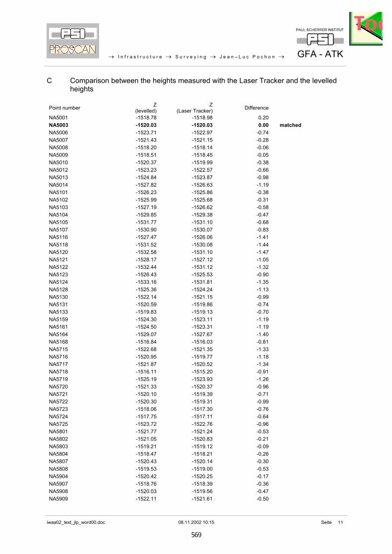
C Comparison between the heights measured with the Laser Tracker and the levelled heights
Point number Z
(levelled) Z
(Laser Tracker) Difference
NA5001 -1518.78 -1518.98 0.20 NA5003 -1520.03 -1520.03 0.00 matched NA5006 -1523.71 -1522.97 -0.74 NA5007 -1521.43 -1521.15 -0.28 NA5008 -1518.20 -1518.14 -0.06 NA5009 -1518.51 -1518.45 -0.05 NA5010 -1520.37 -1519.99 -0.38 NA5012 -1523.23 -1522.57 -0.66 NA5013 -1524.84 -1523.87 -0.98 NA5014 -1527.82 -1526.63 -1.19 NA5101 -1526.23 -1525.86 -0.38 NA5102 -1525.99 -1525.68 -0.31 NA5103 -1527.19 -1526.62 -0.58 NA5104 -1529.85 -1529.38 -0.47 NA5105 -1531.77 -1531.10 -0.68 NA5107 -1530.90 -1530.07 -0.83 NA5116 -1527.47 -1526.06 -1.41 NA5118 -1531.52 -1530.08 -1.44 NA5120 -1532.58 -1531.10 -1.47 NA5121 -1528.17 -1527.12 -1.05 NA5122 -1532.44 -1531.12 -1.32 NA5123 -1526.43 -1525.53 -0.90 NA5124 -1533.16 -1531.81 -1.35 NA5128 -1525.36 -1524.24 -1.13 NA5130 -1522.14 -1521.15 -0.99 NA5131 -1520.59 -1519.86 -0.74 NA5133 -1519.83 -1519.13 -0.70 NA5159 -1524.30 -1523.11 -1.19 NA5161 -1524.50 -1523.31 -1.19 NA5164 -1529.07 -1527.67 -1.40 NA5168 -1516.84 -1516.03 -0.81 NA5715 -1522.68 -1521.35 -1.33 NA5716 -1520.95 -1519.77 -1.18 NA5717 -1521.87 -1520.52 -1.34 NA5718 -1516.11 -1515.20 -0.91 NA5719 -1525.19 -1523.93 -1.26 NA5720 -1521.33 -1520.37 -0.96 NA5721 -1520.10 -1519.39 -0.71 NA5722 -1520.30 -1519.31 -0.99 NA5723 -1518.06 -1517.30 -0.76 NA5724 -1517.75 -1517.11 -0.64 NA5725 -1523.72 -1522.76 -0.96 NA5801 -1521.77 -1521.24 -0.53 NA5802 -1521.05 -1520.83 -0.21 NA5803 -1519.21 -1519.12 -0.09 NA5804 -1518.47 -1518.21 -0.26 NA5807 -1520.43 -1520.14 -0.30 NA5808 -1519.53 -1519.00 -0.53 NA5904 -1520.42 -1520.25 -0.17 NA5907 -1518.76 -1518.39 -0.36 NA5908 -1520.03 -1519.56 -0.47 NA5909 -1522.11 -1521.61 -0.50

→ I n f r a s t r u c t u r e → S u r v e y i n g → J e a n – L u c P o c h o n →
iwaa02_text_jlp_word00.doc 08.11.2002 10:15 Seite
12
D Transformed coordinates
Point number X Y Z NA5001 195623.253 695701.928 -1518.832NA5003 192016.537 689993.269 -1520.138NA5006 185157.777 695699.238 -1523.665NA5007 192456.872 723914.342 -1521.428NA5008 195949.632 721412.012 -1518.125NA5009 195955.586 719414.978 -1518.428NA5010 191933.899 720022.323 -1520.294NA5012 187357.451 726084.657 -1523.275NA5013 182358.203 726084.321 -1524.970NA5014 178057.271 726084.374 -1528.079NA5101 185422.458 682188.878 -1526.443NA5102 185424.895 679657.792 -1526.252NA5103 183421.028 682190.444 -1527.366NA5104 183531.083 679660.060 -1530.103NA5105 182276.730 682188.254 -1531.935NA5107 180871.790 683597.945 -1531.033NA5116 176113.909 690607.673 -1527.447NA5118 176113.402 692593.001 -1531.473NA5120 176120.629 694116.720 -1532.512NA5121 180957.456 694343.298 -1528.138NA5122 178055.166 696190.801 -1532.386NA5123 182371.466 695753.945 -1526.446NA5124 178055.834 698195.018 -1533.086NA5128 181014.691 700712.083 -1525.291NA5130 182430.384 702127.521 -1522.100NA5131 184955.326 702353.308 -1520.606NA5133 186844.634 704243.293 -1519.742NA5159 177924.849 687427.182 -1524.334NA5161 179042.869 692635.597 -1524.478NA5164 176515.696 692266.121 -1529.037NA5168 185549.737 704453.156 -1516.749NA5704 188325.929 716923.061 -1517.675NA5715 179111.870 704839.762 -1522.583NA5716 180746.980 710634.407 -1520.910NA5717 179151.628 711846.021 -1521.798NA5718 184691.628 712727.363 -1516.035NA5719 178958.367 721747.852 -1525.277NA5720 183300.640 722929.072 -1521.382NA5721 187667.133 722432.018 -1520.050NA5722 183199.702 713799.944 -1520.271NA5723 186773.571 712874.691 -1517.968NA5725 182639.916 725324.605 -1523.838NA5801 189012.340 706408.290 -1521.693NA5802 193457.455 706413.204 -1520.926NA5803 193456.849 709908.847 -1519.235NA5804 193454.485 713408.977 -1518.351NA5807 192040.104 710057.542 -1520.366NA5808 188884.632 709568.126 -1519.480NA5904 192031.571 700044.231 -1520.418NA5907 189598.864 703212.055 -1518.777NA5908 188817.212 701539.883 -1519.996NA5909 187658.058 701270.624 -1522.131

→ I n f r a s t r u c t u r e → S u r v e y i n g → J e a n – L u c P o c h o n →
iwaa02_text_jlp_word00.doc 08.11.2002 10:15 Seite
13
E Comparison between the transformed heights and the levelled heights
Point number Z (levelled)
Z(Laser Tracker /
transformed)Difference
NA5001 -1518.78 -1518.832 0.05NA5003 -1520.03 -1520.138 0.11NA5006 -1523.71 -1523.665 -0.04NA5007 -1521.43 -1521.428 0.00NA5008 -1518.20 -1518.125 -0.07NA5009 -1518.51 -1518.428 -0.08NA5010 -1520.37 -1520.294 -0.08NA5012 -1523.23 -1523.275 0.05NA5013 -1524.84 -1524.970 0.13NA5014 -1527.82 -1528.079 0.26NA5101 -1526.23 -1526.443 0.21NA5102 -1525.99 -1526.252 0.27NA5103 -1527.19 -1527.366 0.17NA5104 -1529.85 -1530.103 0.25NA5105 -1531.77 -1531.935 0.16NA5107 -1530.90 -1531.033 0.13NA5116 -1527.47 -1527.447 -0.03NA5118 -1531.52 -1531.473 -0.05NA5120 -1532.58 -1532.512 -0.06NA5121 -1528.17 -1528.138 -0.03NA5122 -1532.44 -1532.386 -0.05NA5123 -1526.43 -1526.446 0.01NA5124 -1533.16 -1533.086 -0.07NA5128 -1525.36 -1525.291 -0.07NA5130 -1522.14 -1522.100 -0.04NA5131 -1520.59 -1520.606 0.01NA5133 -1519.83 -1519.742 -0.09NA5159 -1524.30 -1524.334 0.04NA5161 -1524.50 -1524.478 -0.02NA5164 -1529.07 -1529.037 -0.03NA5168 -1516.84 -1516.749 -0.09NA5715 -1522.68 -1522.583 -0.10NA5716 -1520.95 -1520.910 -0.04NA5717 -1521.87 -1521.798 -0.07NA5718 -1516.11 -1516.035 -0.07NA5719 -1525.19 -1525.277 0.09NA5720 -1521.33 -1521.382 0.05NA5721 -1520.10 -1520.050 -0.05NA5722 -1520.30 -1520.271 -0.03NA5723 -1518.06 -1517.968 -0.09NA5724 -1517.75 -1517.675 -0.07NA5725 -1523.72 -1523.838 0.12NA5801 -1521.77 -1521.693 -0.08NA5802 -1521.05 -1520.926 -0.12NA5803 -1519.21 -1519.235 0.03NA5804 -1518.47 -1518.351 -0.12NA5807 -1520.43 -1520.366 -0.07NA5808 -1519.53 -1519.480 -0.05NA5904 -1520.42 -1520.418 0.00NA5907 -1518.76 -1518.777 0.02NA5908 -1520.03 -1519.996 -0.03NA5909 -1522.11 -1522.131 0.02