Embed Size (px)
Citation preview
1
1st OMG Software-Based Communications (SBC) Workshop:From Mobile to Agile Communications
September 13-16, 2004 - Arlington, VA USA
Jeffrey H. Reed and Raqibul MostafaMobile and Portable Radio Research Group (MPRG), ECE
DepartmentVirginia Tech
[email protected] POLYTECHNIC INSTITUTEAND STATE UNIVERSITY
TechVirginia
1 8 7 2
MOBILE & PORTABLE RADIO RESEARCH GROUP
MPRG
2
Outline• Smart Antennas for Software Radios
– Fundamentals– Algorithms
• Implementation Issues– Hardware– Software
• Case Studies• Future Directions
3
Smart Antennas for Software Radio
4
What is a Smart Antenna
• Definition– Antenna array system aided by some “smart” algorithm to
combine the signals, designed to adapt to different signal environments
– The antenna can automatically adjust to a dynamic signal environment
• Mechanisms– The gain of the antenna for a given direction of arrival is
adjustable– Take advantage of different channels for different antennas
• Some antennas are “smarter” than others
5
Smart Antennas in Software Radios
• Software radios and smart antennas complement each other
• Software radios need to adapt to different protocols, systems and channel environments– Smart antennas aid software radios in attaining this flexibility
through the use of signal processing algorithms to combine the received signals in an optimum manner
– Smart antennas provide the benefits that motivate the adoption of software radios
• Implementation of smart antenna algorithms require flexibility in the infrastructure which is provided by software radios
6
Motivation
• Recent years have seen a great proliferation of wireless systems for higher data rates and more capacity
– PCS: IS-95, GSM, IS-136 (9.6 – 14.4 kbps)– WLAN: IEEE 802.11, Bluetooth, HomeRF (30 kbps – 50 Mbps+)– 2.5G: GPRS, EDGE (115 – 144 kbps)– 3G: WCDMA, CDMA2000, EVDO, EVDV, HSDPA (2-10 Mbps)
• Interference environment becomes increasingly hostile as the number of active devices and standards increases
– Capacity limitation– Advanced methods are necessary to overcome these problems– Military-derived techniques useful– Interference is a big issue in migration of technology
7
Benefits of Smart Antennas (1/2)
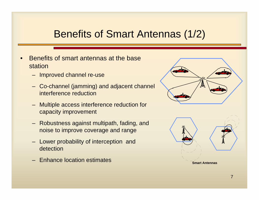
• Benefits of smart antennas at the base station– Improved channel re-use
– Co-channel (jamming) and adjacent channel interference reduction
– Multiple access interference reduction for capacity improvement
– Robustness against multipath, fading, and noise to improve coverage and range
– Lower probability of interception and detection
– Enhance location estimates Smart Antennas
8
Benefits of Smart Antennas (2/2)
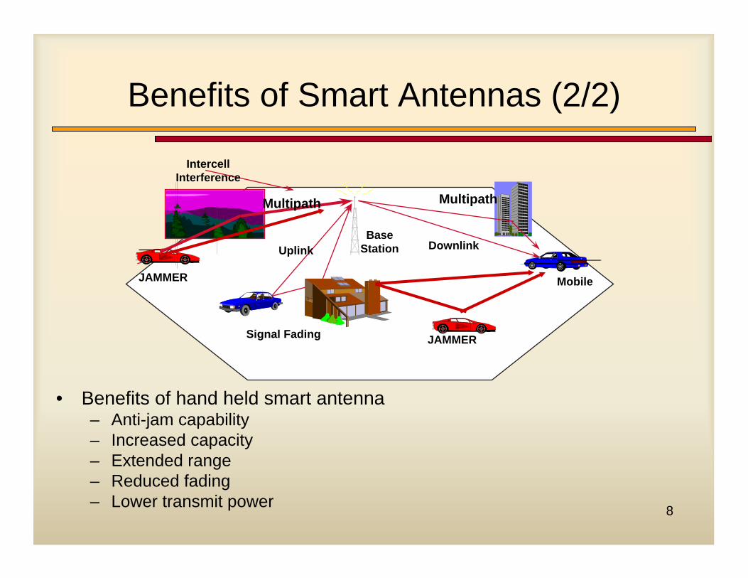
BaseStation
JAMMER
Multipath
Uplink
Mobile
Downlink
Multipath
IntercellInterference
Signal Fading JAMMER
• Benefits of hand held smart antenna– Anti-jam capability– Increased capacity– Extended range– Reduced fading– Lower transmit power
9
Smart Antenna Combining Techniques
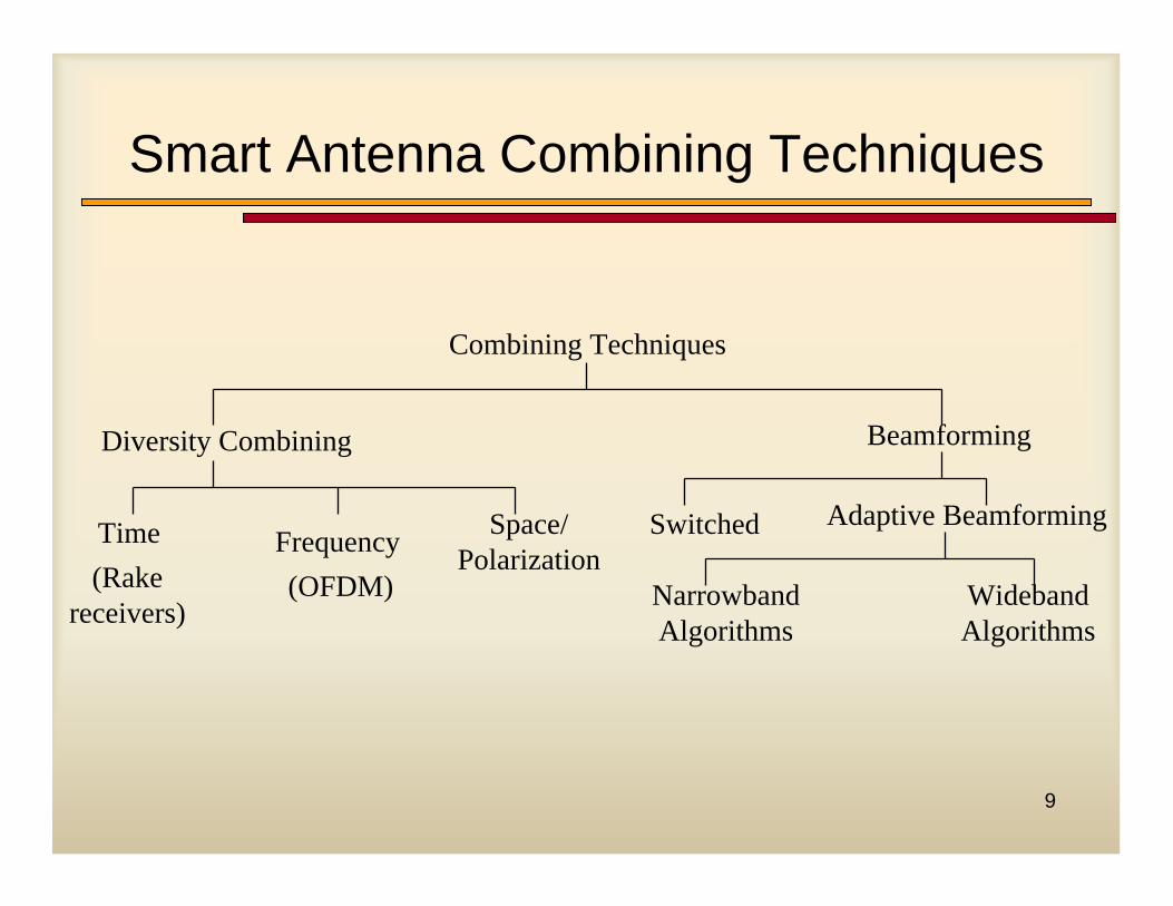
Combining Techniques
Diversity Combining
Adaptive Beamforming
(Rake receivers)
Space/ Polarization
Time Frequency(OFDM) Narrowband
AlgorithmsWideband Algorithms
Beamforming
Switched
10
Diversity vs. Beamforming
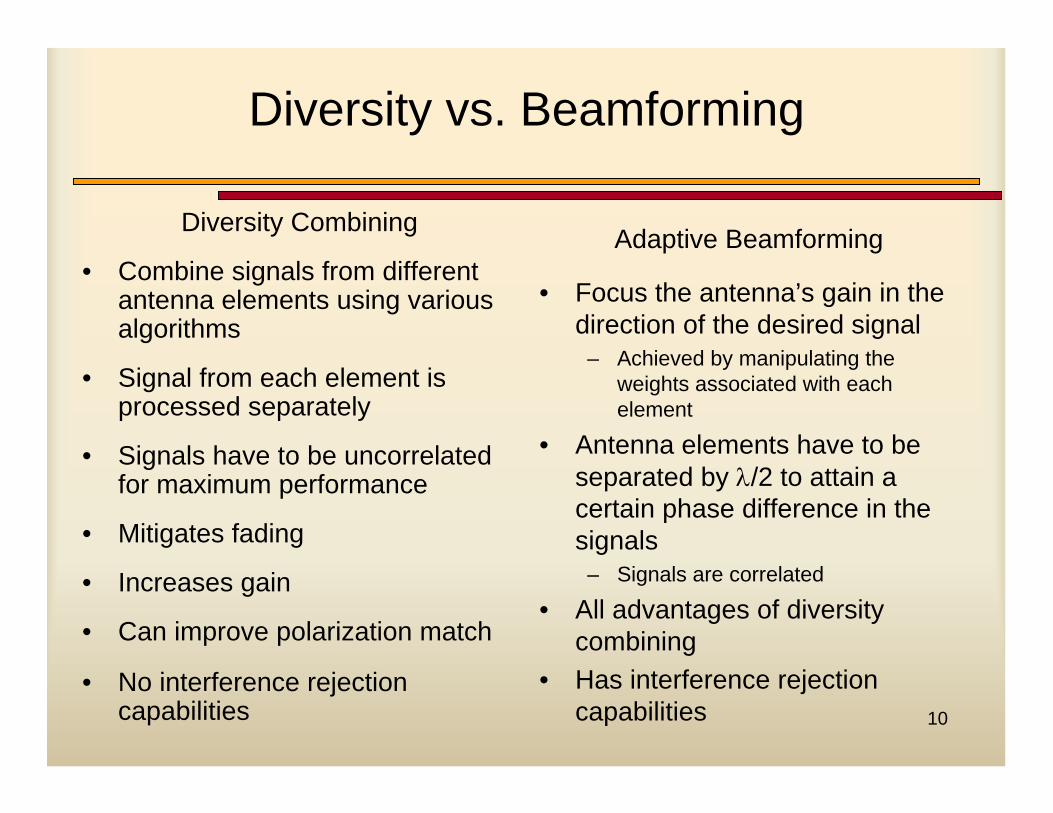
Diversity Combining
• Combine signals from different antenna elements using various algorithms
• Signal from each element is processed separately
• Signals have to be uncorrelated for maximum performance
• Mitigates fading
• Increases gain
• Can improve polarization match
• No interference rejection capabilities
Adaptive Beamforming
• Focus the antenna’s gain in the direction of the desired signal
– Achieved by manipulating the weights associated with each element
• Antenna elements have to be separated by λ/2 to attain a certain phase difference in the signals
– Signals are correlated
• All advantages of diversity combining
• Has interference rejection capabilities
11
Antenna Diversity Principles
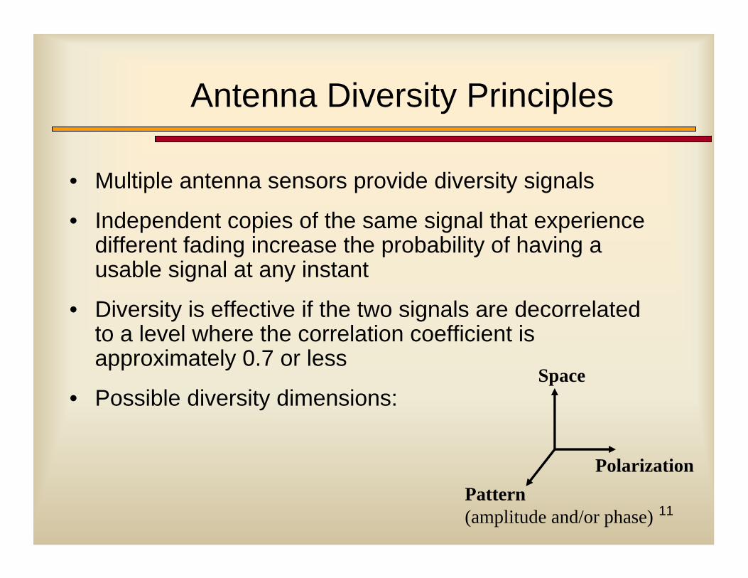
• Multiple antenna sensors provide diversity signals
• Independent copies of the same signal that experience different fading increase the probability of having a usable signal at any instant
• Diversity is effective if the two signals are decorrelated to a level where the correlation coefficient is approximately 0.7 or less
• Possible diversity dimensions:Space
PolarizationPattern (amplitude and/or phase)
12
Transmit Diversity
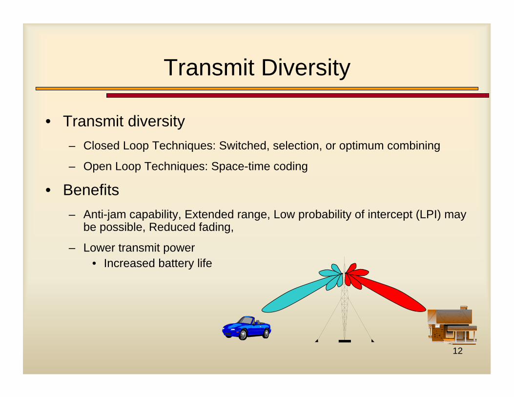
• Transmit diversity– Closed Loop Techniques: Switched, selection, or optimum combining
– Open Loop Techniques: Space-time coding
• Benefits– Anti-jam capability, Extended range, Low probability of intercept (LPI) may
be possible, Reduced fading,
– Lower transmit power• Increased battery life
13
Transmit Diversity Techniques
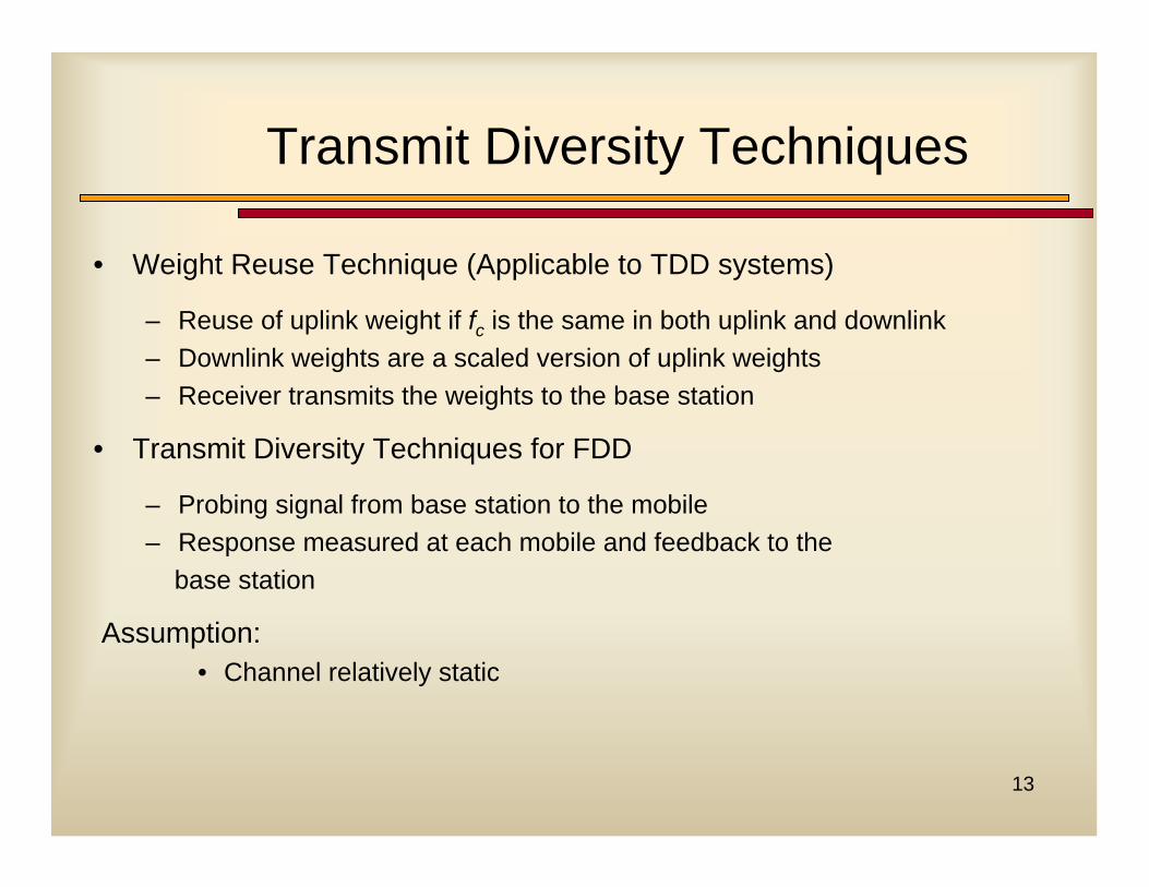
• Weight Reuse Technique (Applicable to TDD systems)
– Reuse of uplink weight if fc is the same in both uplink and downlink– Downlink weights are a scaled version of uplink weights– Receiver transmits the weights to the base station
• Transmit Diversity Techniques for FDD
– Probing signal from base station to the mobile– Response measured at each mobile and feedback to the
base station
Assumption:• Channel relatively static
14
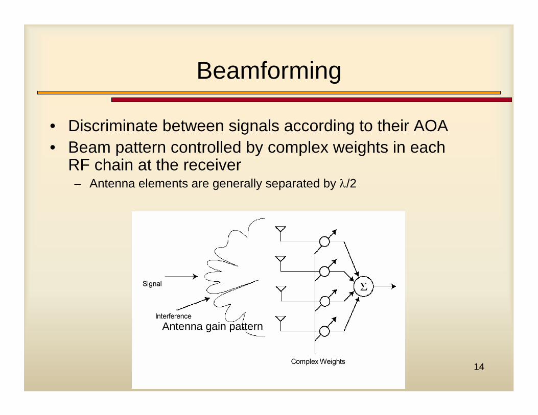
Beamforming
• Discriminate between signals according to their AOA• Beam pattern controlled by complex weights in each
RF chain at the receiver– Antenna elements are generally separated by λ/2
Antenna gain pattern
15
Beam Patterns
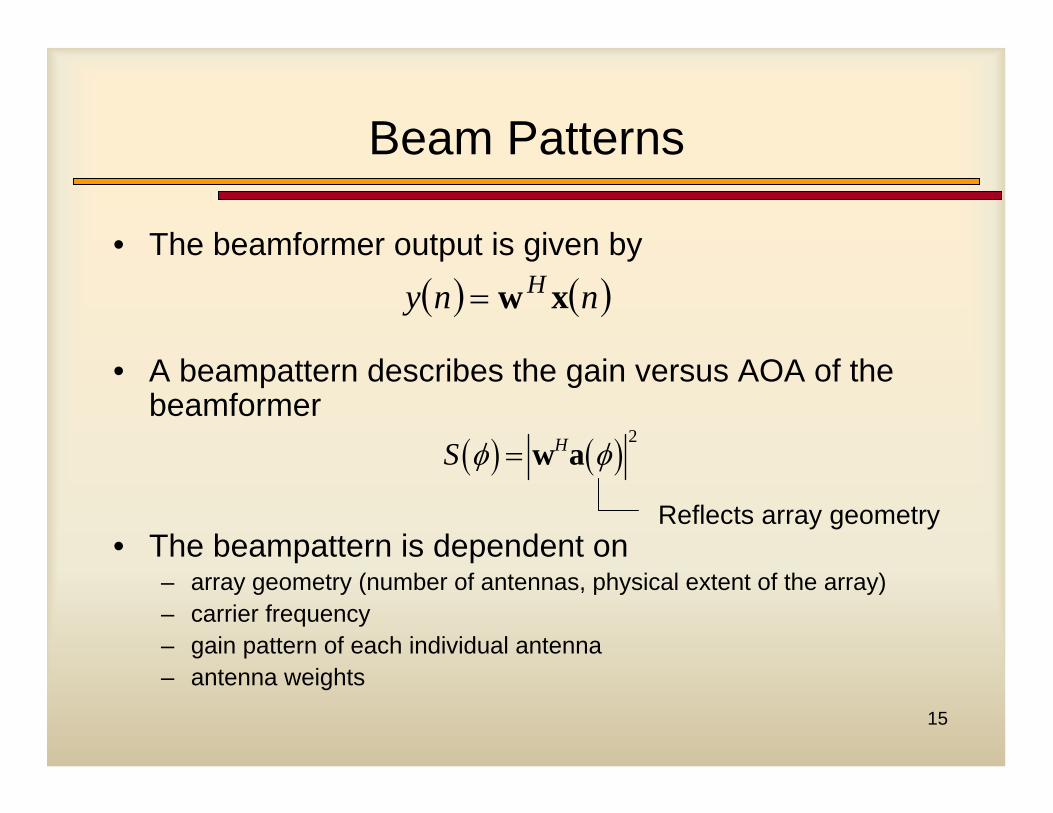
• The beamformer output is given by
• A beampattern describes the gain versus AOA of the beamformer
• The beampattern is dependent on– array geometry (number of antennas, physical extent of the array)– carrier frequency– gain pattern of each individual antenna– antenna weights
( ) ( )nny H xw=
( ) ( ) 2HS φ φ= w a
Reflects array geometry
16
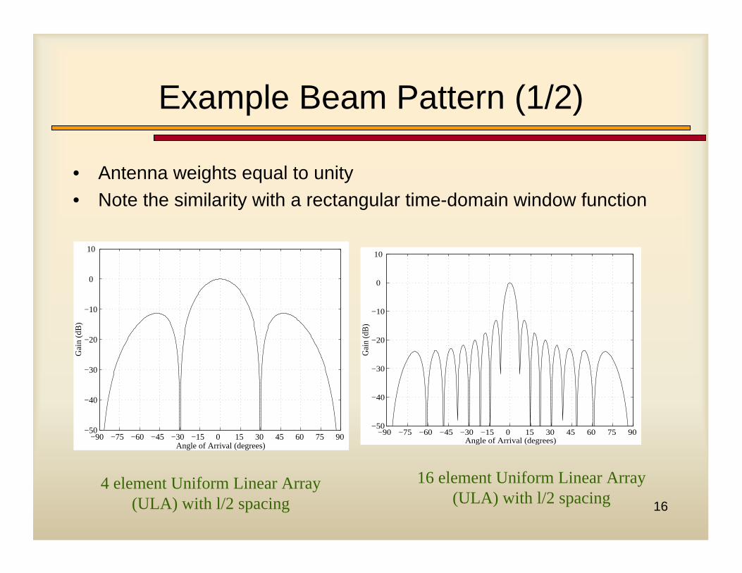
Example Beam Pattern (1/2)
• Antenna weights equal to unity• Note the similarity with a rectangular time-domain window function
−90 −75 −60 −45 −30 −15 0 15 30 45 60 75 90 −50
−40
−30
−20
−10
0
10
Angle of Arrival (degrees)
Gai
n (d
B)
−90 −75 −60 −45 −30 −15 0 15 30 45 60 75 90 −50
−40
−30
−20
−10
0
10
Angle of Arrival (degrees)
Gai
n (d
B)
4 element Uniform Linear Array (ULA) with l/2 spacing
16 element Uniform Linear Array (ULA) with l/2 spacing
17
Example Beam Pattern (2/2)
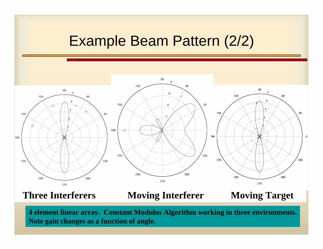
Three Interferers Moving Interferer Moving Target
4 element linear array. Constant Modulus Algorithm working in three environments.Note gain changes as a function of angle.
18
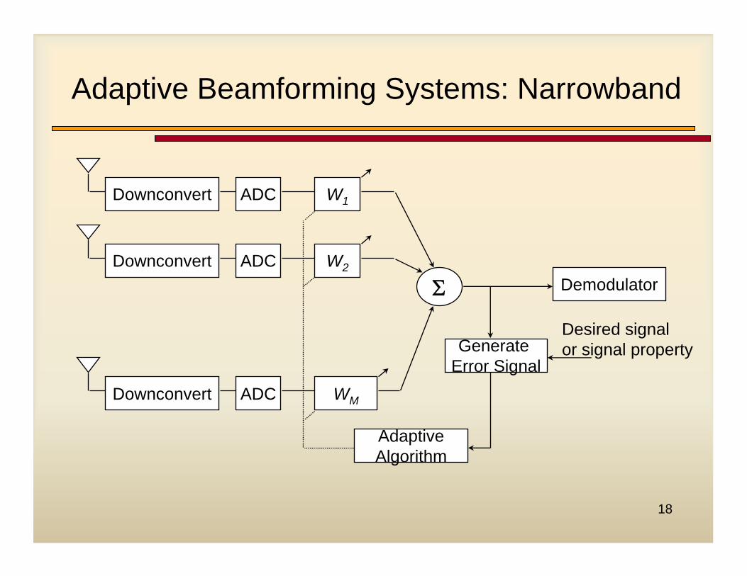
Adaptive Beamforming Systems: Narrowband
Downconvert ADC W1
Downconvert ADC W2
Downconvert ADC WM
Σ
AdaptiveAlgorithm
Generate Error Signal
Demodulator
Desired signal or signal property
19
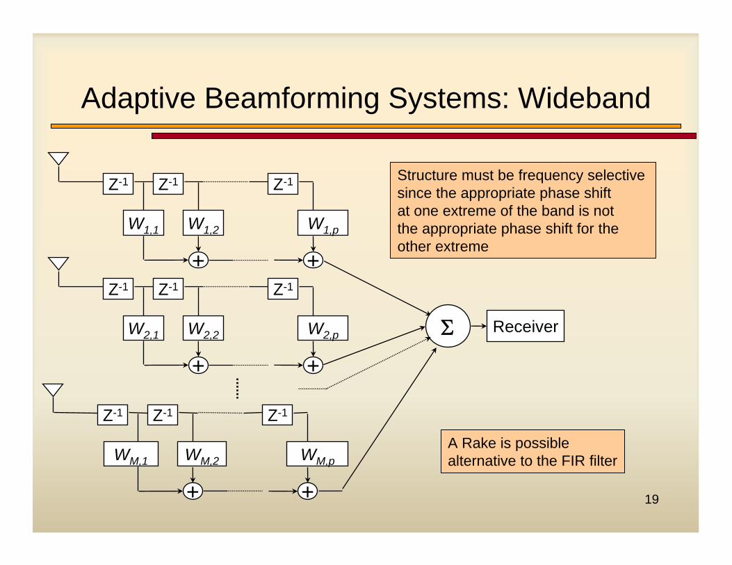
Z-1 Z-1 Z-1
W1,1 W1,2 W1,p
+ +
Σ
Z-1 Z-1 Z-1
W2,1 W2,2 W2,p
+ +
Z-1 Z-1 Z-1
WM,1 WM,2 WM,p
+ +
Receiver
Structure must be frequency selective since the appropriate phase shift at one extreme of the band is not the appropriate phase shift for the other extreme
A Rake is possible alternative to the FIR filter
Adaptive Beamforming Systems: Wideband
20
Analogy Between Adaptive Antennas and Equalizers
• Antenna arrays are formed by combining the signals from a number of antenna elements (frequently spaced one half wavelength apart)
• Algorithms which weight coefficients form a “spatial filter”
• Goal is usually to minimize MSE in resulting signal
• Adaptive algorithms such as LMS or RLS can be used to steer the resulting antenna beam
21
Smart Antenna and SDR: Hardware Issues
22
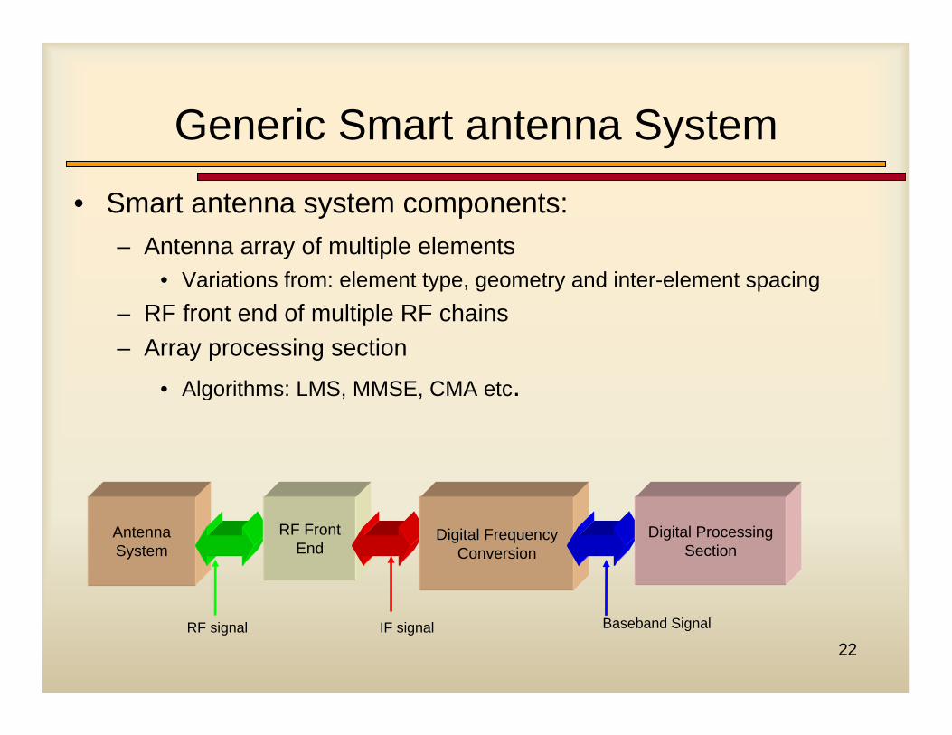
Generic Smart antenna System
• Smart antenna system components:– Antenna array of multiple elements
• Variations from: element type, geometry and inter-element spacing– RF front end of multiple RF chains– Array processing section
• Algorithms: LMS, MMSE, CMA etc.
Antenna System
RF signal IF signal Baseband Signal
RF Front End
Digital Frequency Conversion
Digital ProcessingSection
23
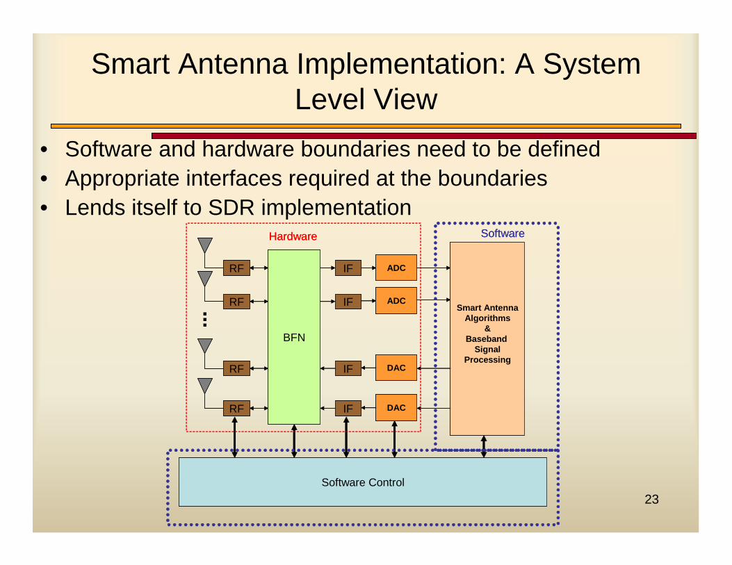
Smart Antenna Implementation: A System Level View
• Software and hardware boundaries need to be defined• Appropriate interfaces required at the boundaries• Lends itself to SDR implementation
RF
RF
RF
BFN
IF
IF
IF
ADC
ADC
DAC
RF IF DAC
Smart AntennaAlgorithms
& Baseband
SignalProcessing
Software Control
Hardware Software
RF
RF
RF
BFN
IF
IF
IF
ADC
ADC
DAC
RF IF DAC
Smart AntennaAlgorithms
& Baseband
SignalProcessing
Software Control
Hardware Software
24
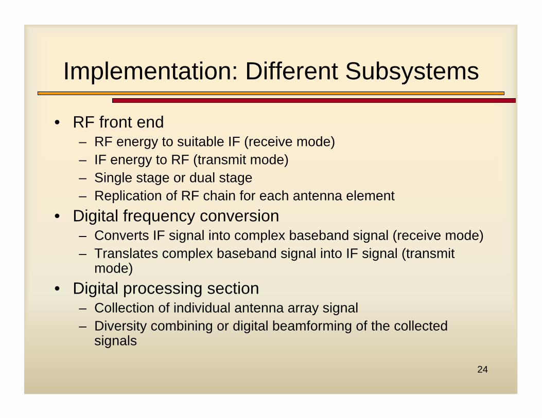
Implementation: Different Subsystems
• RF front end– RF energy to suitable IF (receive mode)– IF energy to RF (transmit mode)– Single stage or dual stage– Replication of RF chain for each antenna element
• Digital frequency conversion– Converts IF signal into complex baseband signal (receive mode)– Translates complex baseband signal into IF signal (transmit
mode)• Digital processing section
– Collection of individual antenna array signal– Diversity combining or digital beamforming of the collected
signals
25
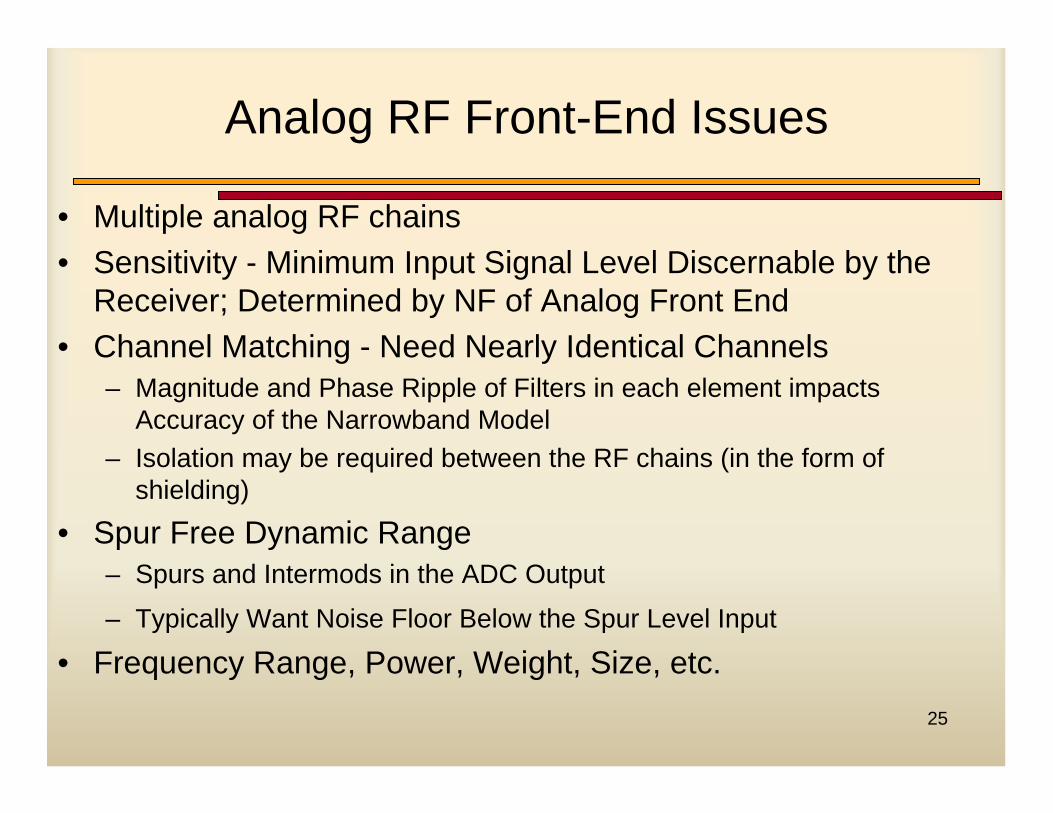
Analog RF Front-End Issues
• Multiple analog RF chains• Sensitivity - Minimum Input Signal Level Discernable by the
Receiver; Determined by NF of Analog Front End• Channel Matching - Need Nearly Identical Channels
– Magnitude and Phase Ripple of Filters in each element impacts Accuracy of the Narrowband Model
– Isolation may be required between the RF chains (in the form of shielding)
• Spur Free Dynamic Range– Spurs and Intermods in the ADC Output
– Typically Want Noise Floor Below the Spur Level Input
• Frequency Range, Power, Weight, Size, etc.
26
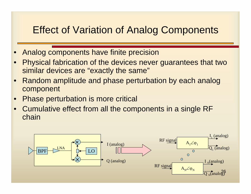
Effect of Variation of Analog Components
• Analog components have finite precision• Physical fabrication of the devices never guarantees that two
similar devices are “exactly the same”• Random amplitude and phase perturbation by each analog
component• Phase perturbation is more critical• Cumulative effect from all the components in a single RF
chain
×LO
LNABPF
×
I (analog)
Q (analog)
I1 (analog)
Q1 (analog)
RF signal A1∠ϕ1
I N(analog)
Q N(analog)
RF signal AN∠ϕN
27
Effect of Variation of Analog Components
• Component variation due to:– Thermal factors– Aging– Stray capacitance at the terminal from improper connection
• Performance sensitive to temperature (ambient or operating) and age of the components
• Sensitivity depends on the quality of the component– Can be solved by using high-precision components
• More expensive– Also solved by “going digital”
• Replace analog components with digital components as much as possible
28
Calibration
• Uncertainties in the array manifold:– Element position error– Mutual coupling– Element amplitude and phase errors– Frequency errors
• Uncertainties in the array manifold limit the performance of direction-finding algorithms or Direction of Arrival (DOA) algorithms
• Direction-finding applications– E911 and location services– Military surveillance
29
DSP/SDR Issues
• Collect data from multiple DDCs• Perform a combining technique on these collected
sampled data• Collection scheme involves sampling each board
sequentially when data is ready• Different schemes
– Design a back-plane interface to DSP– High Speed multiprocessor systems and cross-processor
communication
30
Digital Frequency Converter Issues
• Multiple DDCs/DUCs, each following individual analog RF front-end
• Better precision as magnitude/phase uncertainty not present
• Synchronization needed between individual DDCs/DUCs• Synchronization scheme may be difficult for commercial
DDCs/DUCs as they are not designed for array operation
• Space constraint can be a problem for handset structure
31
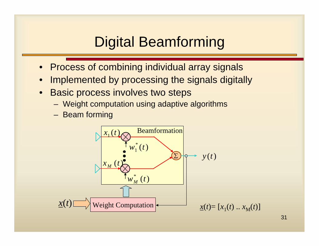
Digital Beamforming• Process of combining individual array signals• Implemented by processing the signals digitally• Basic process involves two steps
– Weight computation using adaptive algorithms– Beam forming
Σ
)(* twM
)(txM
)(1 tx
)(*1 tw
)(ty
Weight Computationx(t)
Beamformation
x(t)= [x1(t) .. xM(t)]
32
Digital Beamforming
• Beam formation– Implements inner product between W and x(t)– Simply multiply and add operation– Processing at a high rate of signal bandwidth
• Weight computation– Updating of W– Implemented by adaptive algorithms
• Performed at a slower rate than beam formation
33
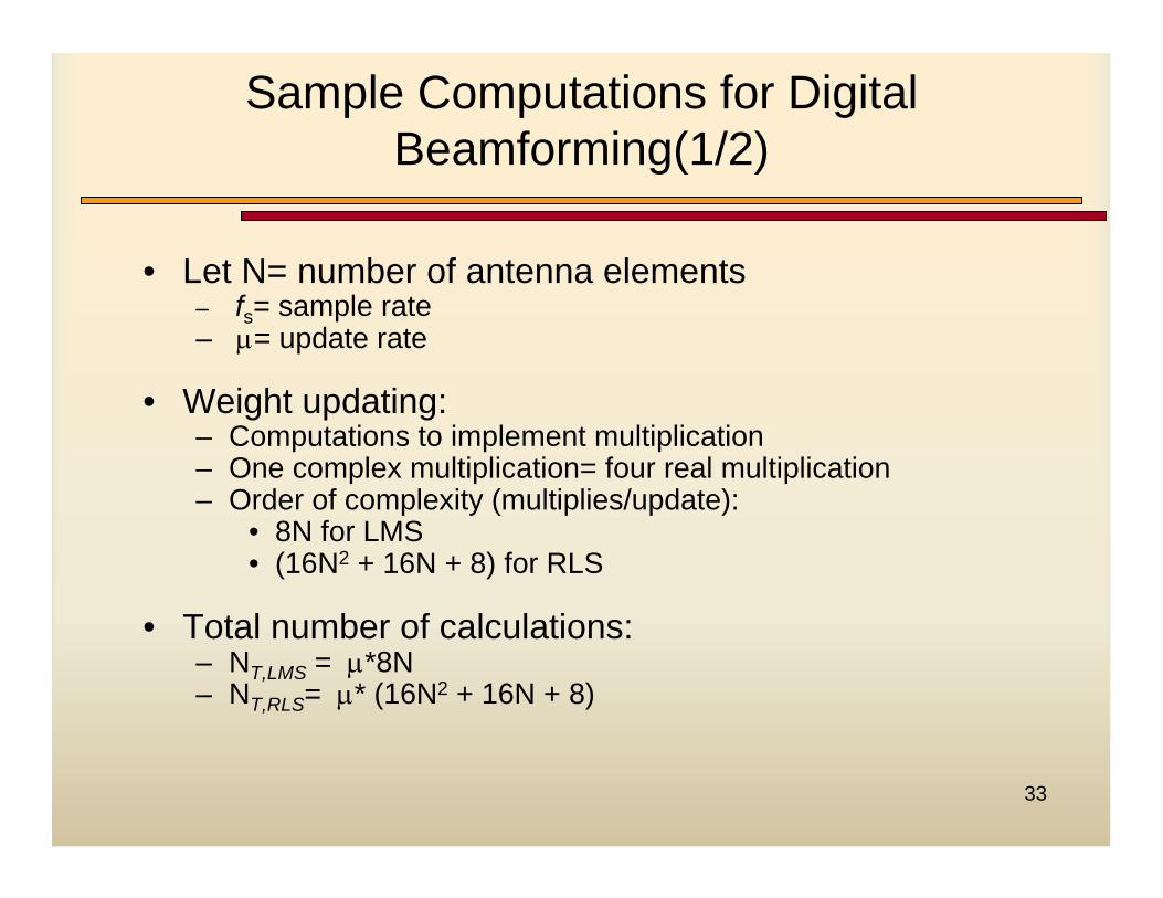
• Let N= number of antenna elements– fs= sample rate– µ= update rate
• Weight updating:– Computations to implement multiplication– One complex multiplication= four real multiplication– Order of complexity (multiplies/update):
• 8N for LMS• (16N2 + 16N + 8) for RLS
• Total number of calculations:– NT,LMS = µ*8N– NT,RLS= µ* (16N2 + 16N + 8)
Sample Computations for Digital Beamforming(1/2)
34
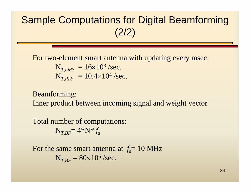
Sample Computations for Digital Beamforming (2/2)
For two-element smart antenna with updating every msec:NT,LMS = 16×103 /sec. NT,RLS = 10.4×10⁴ /sec.
Beamforming:Inner product between incoming signal and weight vector
Total number of computations:NT,BF= 4*N* fs
For the same smart antenna at fs= 10 MHzNT,BF = 80×106 /sec.
35
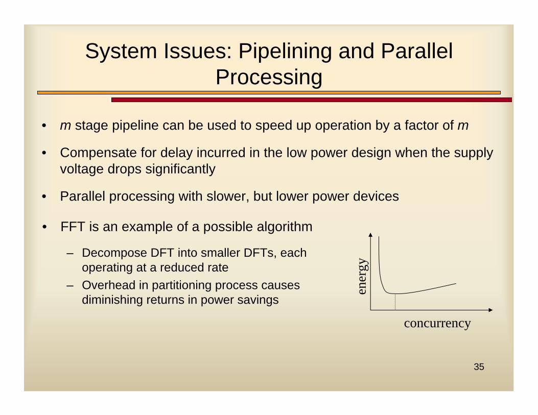
System Issues: Pipelining and Parallel Processing
• m stage pipeline can be used to speed up operation by a factor of m
• Compensate for delay incurred in the low power design when the supply voltage drops significantly
• Parallel processing with slower, but lower power devices
concurrency
ener
gy
• FFT is an example of a possible algorithm
– Decompose DFT into smaller DFTs, each operating at a reduced rate
– Overhead in partitioning process causes diminishing returns in power savings
36
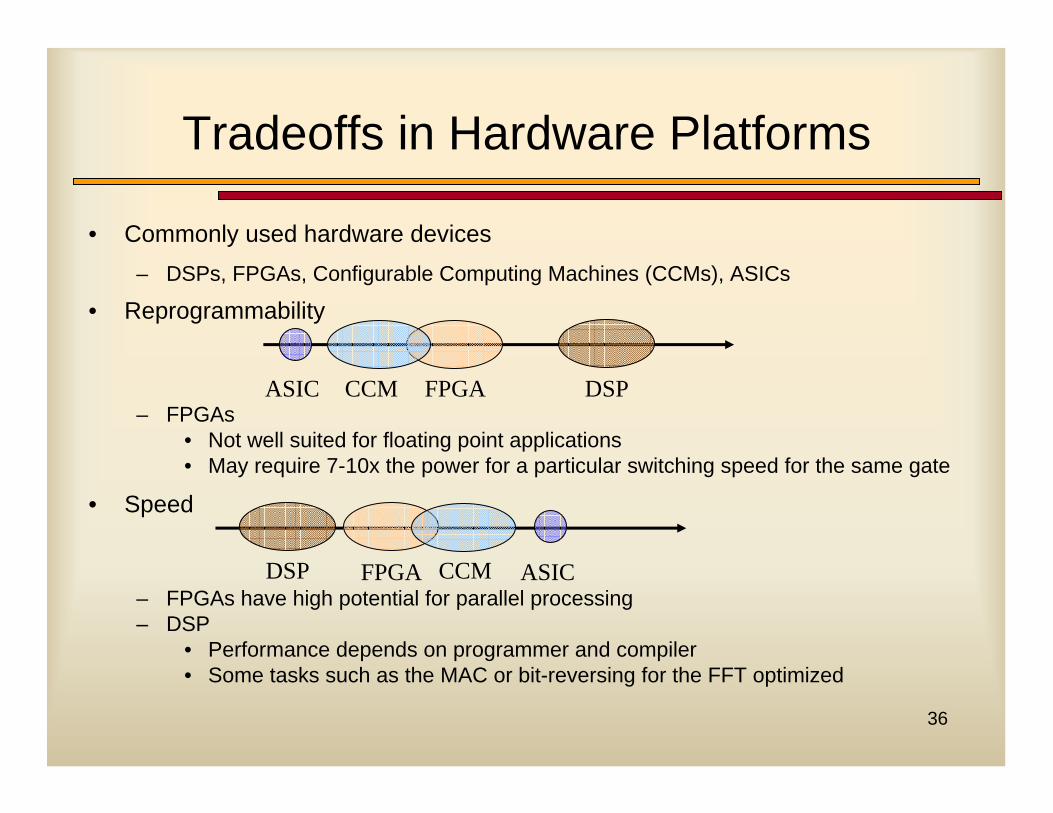
Tradeoffs in Hardware Platforms
• Commonly used hardware devices– DSPs, FPGAs, Configurable Computing Machines (CCMs), ASICs
• Reprogrammability
– FPGAs• Not well suited for floating point applications• May require 7-10x the power for a particular switching speed for the same gate
• Speed
– FPGAs have high potential for parallel processing– DSP
• Performance depends on programmer and compiler• Some tasks such as the MAC or bit-reversing for the FFT optimized
ASIC CCM FPGA DSP
ASICCCMFPGADSP
37
Smart Antenna and SDR: Software Issues
38
Smart Antenna API
• The various SA algorithms must be applicable to SDR-based wireless communication systems such that SA API does not confine to the evolution of communication standards and system hardware.
• Interface between Smart Antenna Base Station (SABS) and SDR network must operate independently of hardware.
• SABS should be partitioned into small modules and each of modules should interface independently of various algorithms and communication standards.
• Functions and capability of each module must be known to the network controller. Thus, Beam-forming module in SABS should be manageable through SDR network.
• Network interface should be independent of system upgrade.
39
What makes a Smart Antenna API Difficult to Create?
• Wide range of smart antenna algorithms• Significant interdependencies with other radio functions
– RF: mixer control, power amp, converters, …– Antenna: type, location parameters– Demod: error correction, synch, rake, interference rejection algorithms,
framing, …– Radio Resource Management: power control, frequency allocation,
QoS, ….
40
Outstanding Questions To Resolve
• How general can it be in practice?• Best approach with working with OMG and JPO?• What is the border between the smart antenna API and
the antenna API?• Is this API more appropriate for SCA 3.0+?• How can it be verified? • Best mode for cooperation in producing API?• How much synergism is there with the Open Base
Station Architecture Initiative (OBSAI) and the Antenna Interface Standards Group (AISG)?
41
Example Smart Antenna API Logical Functionality
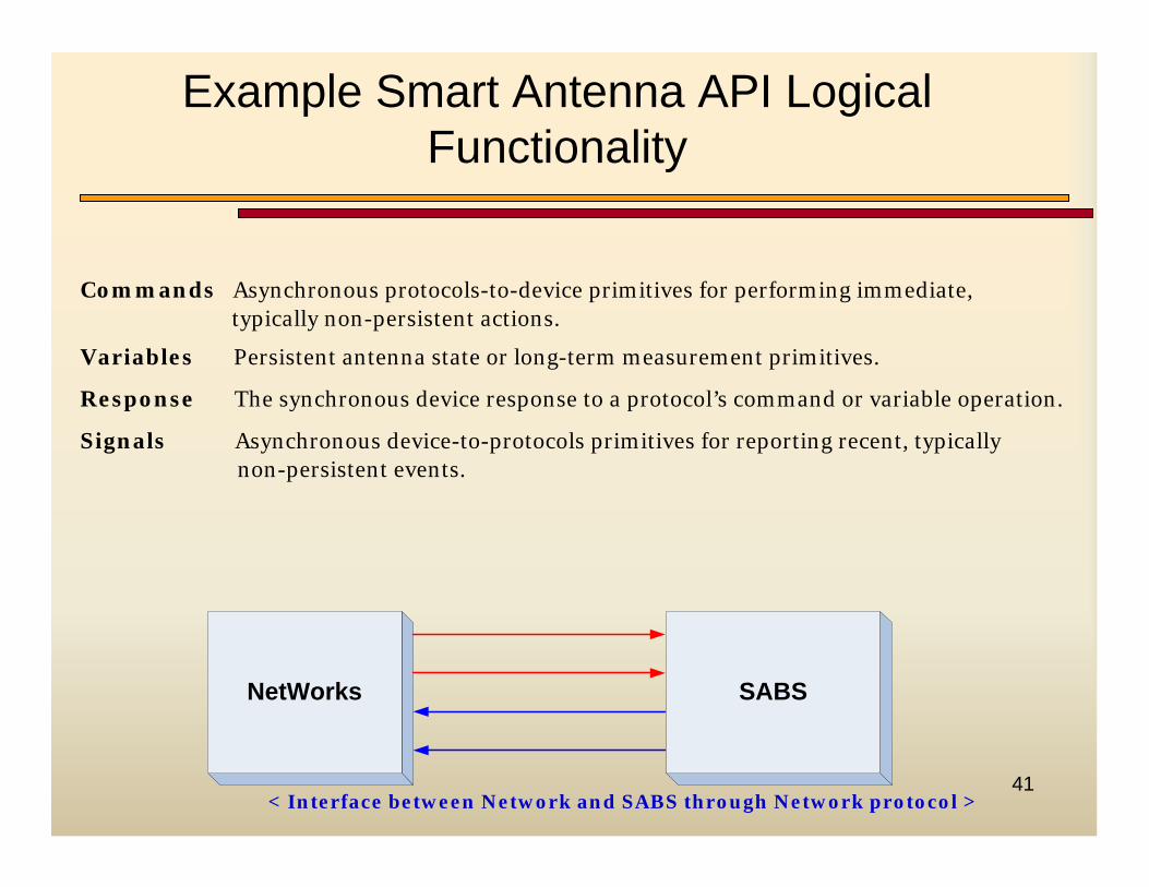
< Interface between Network and SABS through Network protocol >
NetWorks SABS
Commands Asynchronous protocols-to-device primitives for performing immediate,typically non-persistent actions.
Variables Persistent antenna state or long-term measurement primitives.
Response The synchronous device response to a protocol’s command or variable operation.
Signals Asynchronous device-to-protocols primitives for reporting recent, typically non-persistent events.
42
Recent Activities in Creating the API (1/2)
• Smart Antenna Working Group of SDR Forum leading efforts to develop the API
• An OMG submission on RFP for Smart Antenna API is now available
• An RFI on Smart Antenna API will be issued soon through SDR Forum
• The API on Single Antenna is available from SCA Specialized Hardware Subsystem (SHS) working group
43
Recent Activities in Creating the API (2/2)
• The first draft on the architecture for the Smart Antenna Base stations (SBS) is available for CDMA
• Some primitives for smart antenna API have been defined
• Completing the smart antenna API based on the proposed architecture and the primitives constitute the next technical step in the development effort
• Need to think of generic SA-APIs which include other classes of smart antenna implementation eg: MIMO and for mobile terminals
• Need to coordinate with OMG and JPO for inclusion into SCA.
44
Technology Needing Development for Smart Antennas
45
Technology Needing Development for Smart Antennas (1)
• Deployment tools– System layout– Resource allocation and network control algorithms, i.e., handover, channel
allocation, admission control, power control, etc. – Efficient software evaluation tools
• Metrics and analysis procedures for design– Throughput, reliability, capacity
• Low cost hardware– RF and consistency / calibration / flexibility– High resolution low power A/D and flexible DDC (variable bandwidth)– Power amplifiers (key cost for 3G) and synergism with arrays
• Software– API– SCA 3.0 should help with data throughput problems
46
Technology Needing Development for Smart Antennas (2)
• Variable RF capability: High Quality and Multiple Band Support
• Algorithms– Overloaded array capability– Balanced up and down links through interference rejection
• Modulation Synergism– Packet radio capable– Trellis-coded type modulation
• Handset smart antennas with feedback– Power consumption and capacity analysis– Form factors– Trade-offs in space time processing– Peer-to-peer capability
47
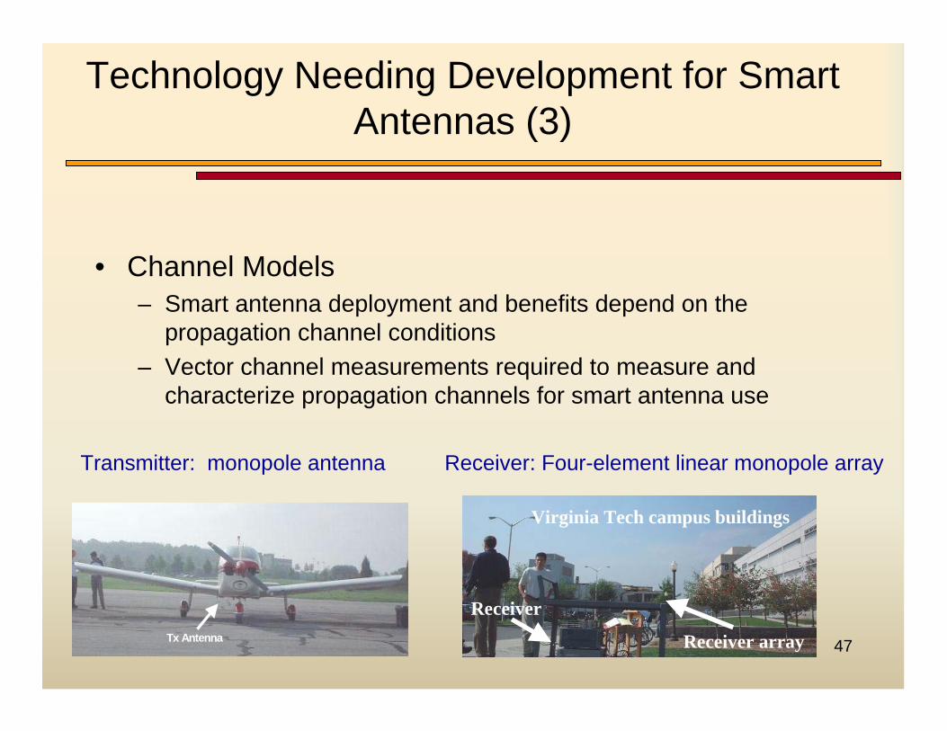
Technology Needing Development for Smart Antennas (3)
• Channel Models– Smart antenna deployment and benefits depend on the
propagation channel conditions– Vector channel measurements required to measure and
characterize propagation channels for smart antenna use
Tx AntennaTx Antenna Receiver array
Receiver
Virginia Tech campus buildings
Receiver array
Receiver
Virginia Tech campus buildings
Transmitter: monopole antenna Receiver: Four-element linear monopole array
48
Technology Needing Development for Smart Antennas (4)
• Regulatory– FCC how do you regulate EIRP to reduce amount of interference
in the system?– How can this technology be mandated to reduce interference?– Development of Smart Antenna API for SCA 2.2 (SDR Forum
and OMG)
49
Case Studies of Smart Antennas
50
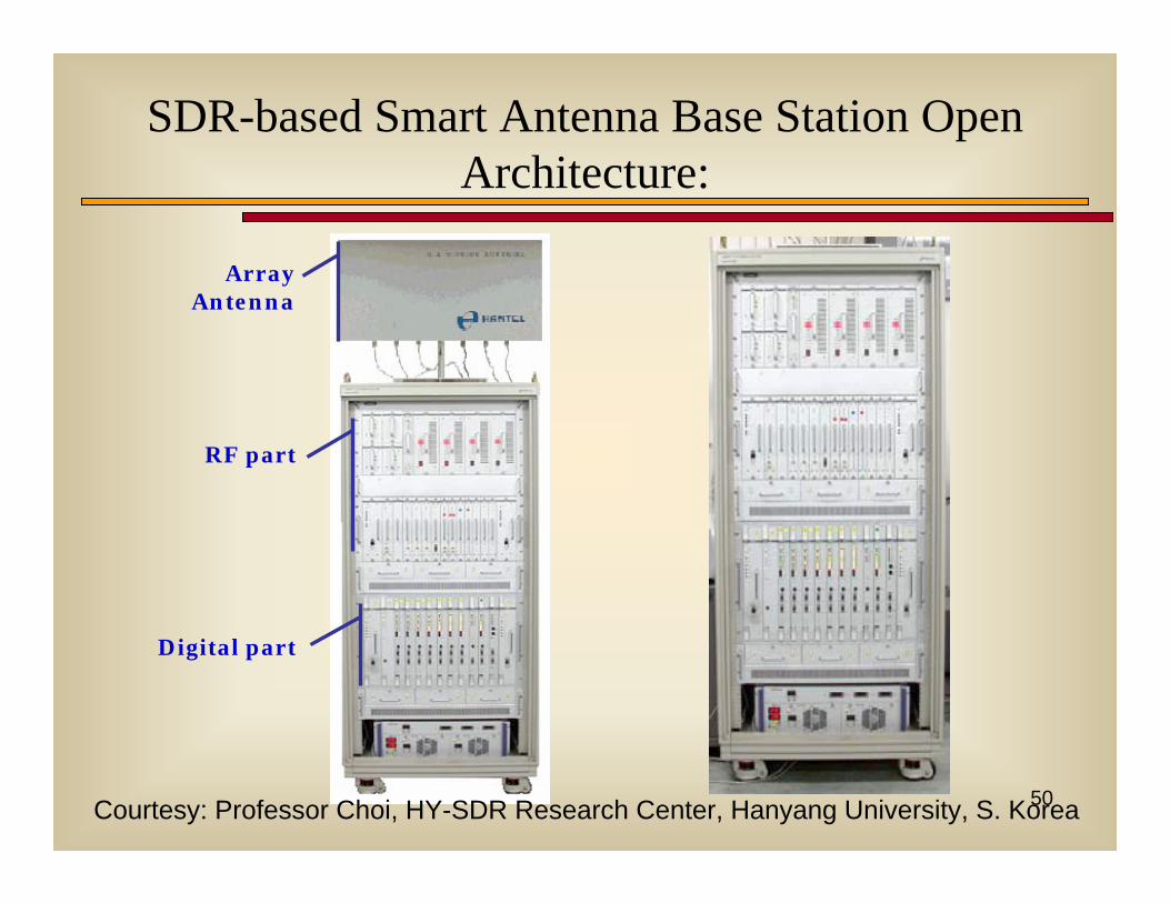
Array Antenna
RF part
Digital part
SDR-based Smart Antenna Base Station Open Architecture:
Courtesy: Professor Choi, HY-SDR Research Center, Hanyang University, S. Korea
51
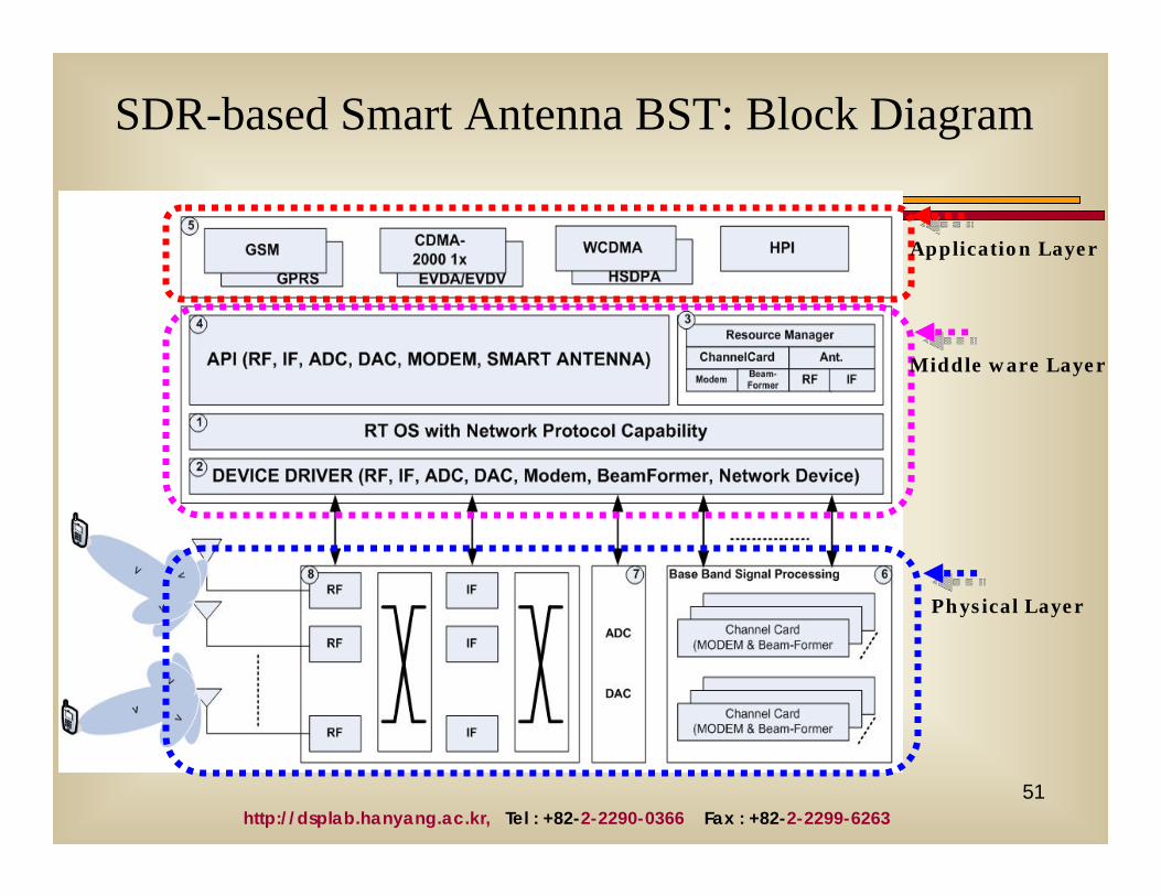
SDR-based Smart Antenna BST: Block Diagram
Application Layer
Middle ware Layer
Physical Layer
http://dsplab.hanyang.ac.kr, Tel : +82-2-2290-0366 Fax : +82-2-2299-6263
52
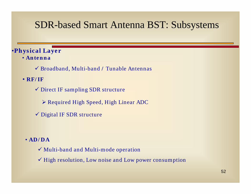
•Physical Layer• Antenna
Broadband, Multi-band / Tunable Antennas
• RF/IF
Direct IF sampling SDR structure
Required High Speed, High Linear ADC
Digital IF SDR structure
• AD/DA
Multi-band and Multi-mode operation
High resolution, Low noise and Low power consumption
SDR-based Smart Antenna BST: Subsystems
53
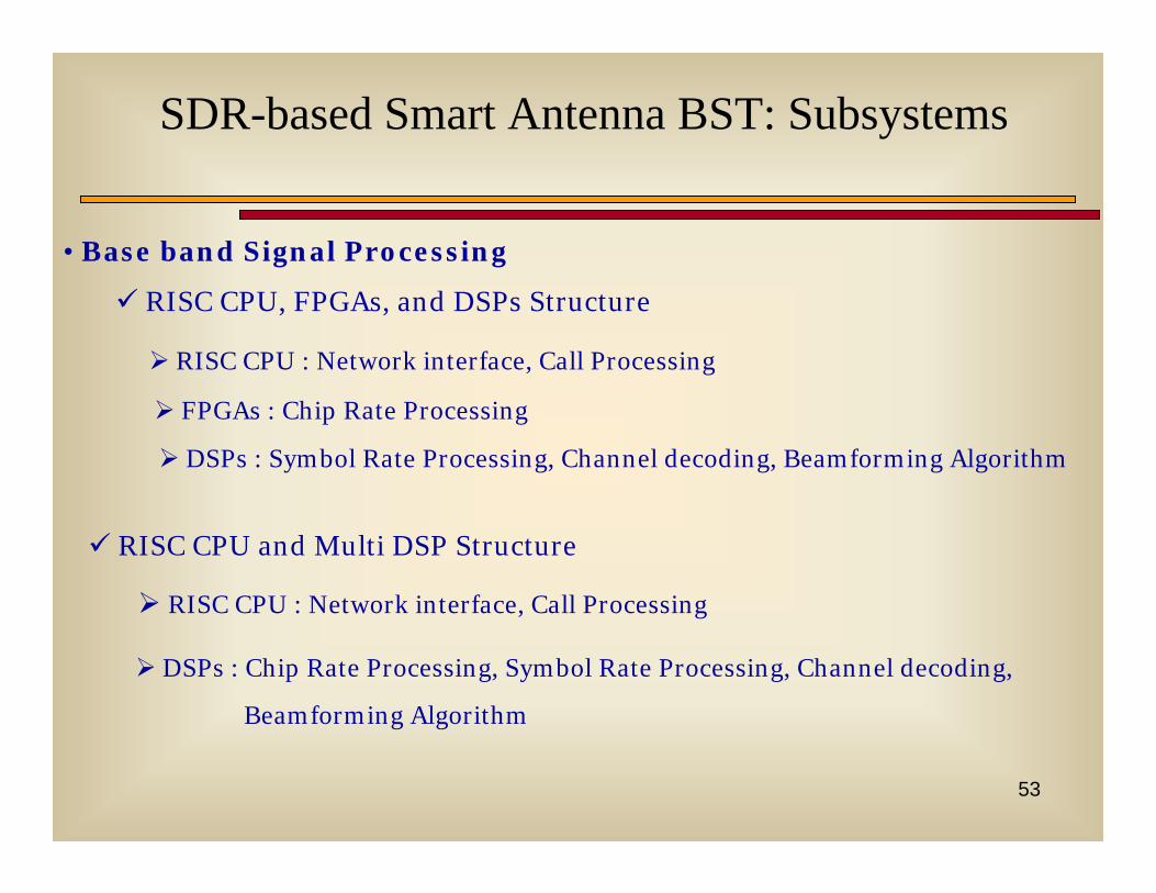
• Base band Signal Processing
RISC CPU, FPGAs, and DSPs Structure
RISC CPU and Multi DSP Structure
RISC CPU : Network interface, Call Processing
FPGAs : Chip Rate Processing
DSPs : Symbol Rate Processing, Channel decoding, Beamforming Algorithm
RISC CPU : Network interface, Call Processing
DSPs : Chip Rate Processing, Symbol Rate Processing, Channel decoding,
Beamforming Algorithm
SDR-based Smart Antenna BST: Subsystems
54
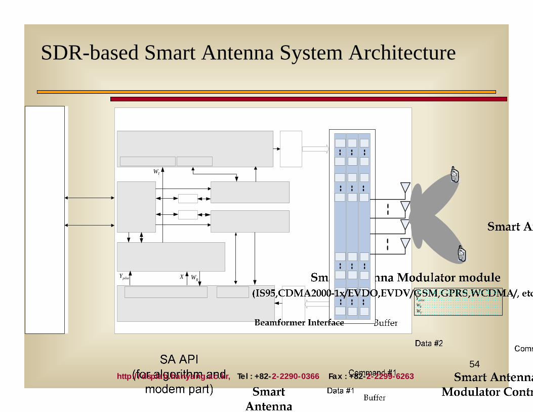
SDR-based Smart Antenna System Architecture
RWpilotY X
TW
TWRW
pilotYX
http://dsplab.hanyang.ac.kr, Tel : +82-2-2290-0366 Fax : +82-2-2299-6263
55
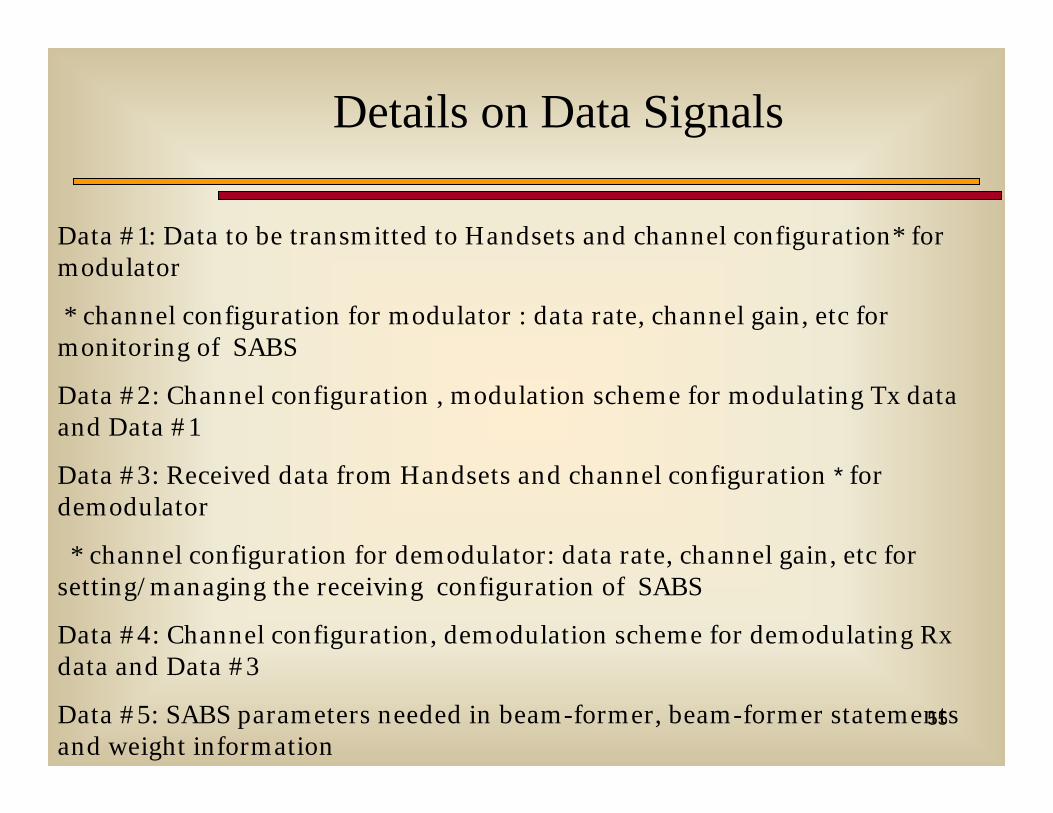
Details on Data Signals
Data #1: Data to be transmitted to Handsets and channel configuration* for modulator
* channel configuration for modulator : data rate, channel gain, etc for monitoring of SABS
Data #2: Channel configuration , modulation scheme for modulating Tx data and Data #1
Data #3: Received data from Handsets and channel configuration * for demodulator
* channel configuration for demodulator: data rate, channel gain, etc for setting/managing the receiving configuration of SABS
Data #4: Channel configuration, demodulation scheme for demodulating Rx data and Data #3
Data #5: SABS parameters needed in beam-former, beam-former statements and weight information
56
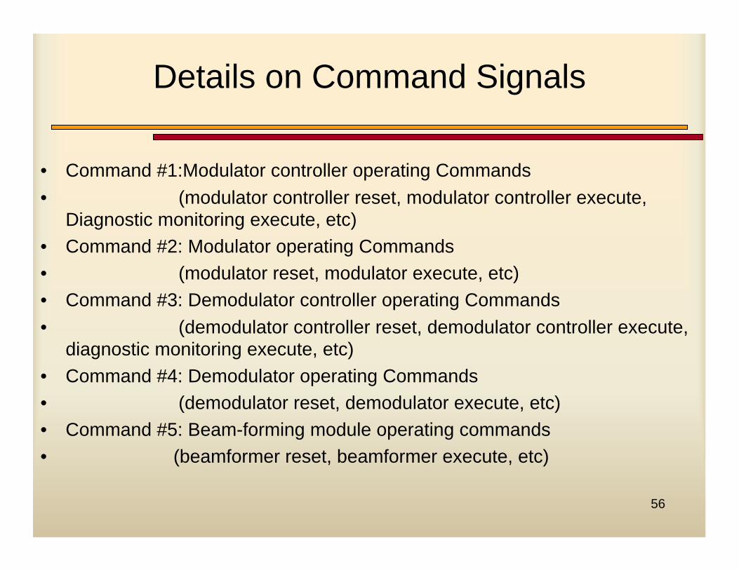
Details on Command Signals
• Command #1:Modulator controller operating Commands• (modulator controller reset, modulator controller execute,
Diagnostic monitoring execute, etc)• Command #2: Modulator operating Commands• (modulator reset, modulator execute, etc)• Command #3: Demodulator controller operating Commands• (demodulator controller reset, demodulator controller execute,
diagnostic monitoring execute, etc)• Command #4: Demodulator operating Commands• (demodulator reset, demodulator execute, etc) • Command #5: Beam-forming module operating commands• (beamformer reset, beamformer execute, etc)
57
MIMO Equalizing Receiver Testbed(1/2)
• A reconfigurable receiver for rapid development and real-time operation from Tait Electronics Ltd, NZ.
• Current implementations allow up to 12 antenna elements at each end
• Multi-Variate Decision Feedback Equalizer (MV-DFE) implemented to counter delay spread in channels
• Parallel FPGA and DSP modules (Altera Statix)• IF sampling rate: 60 MHz• Baseband (input to DFE) sampling rate: 2 MHz• Processing clock: 300 MHz
58
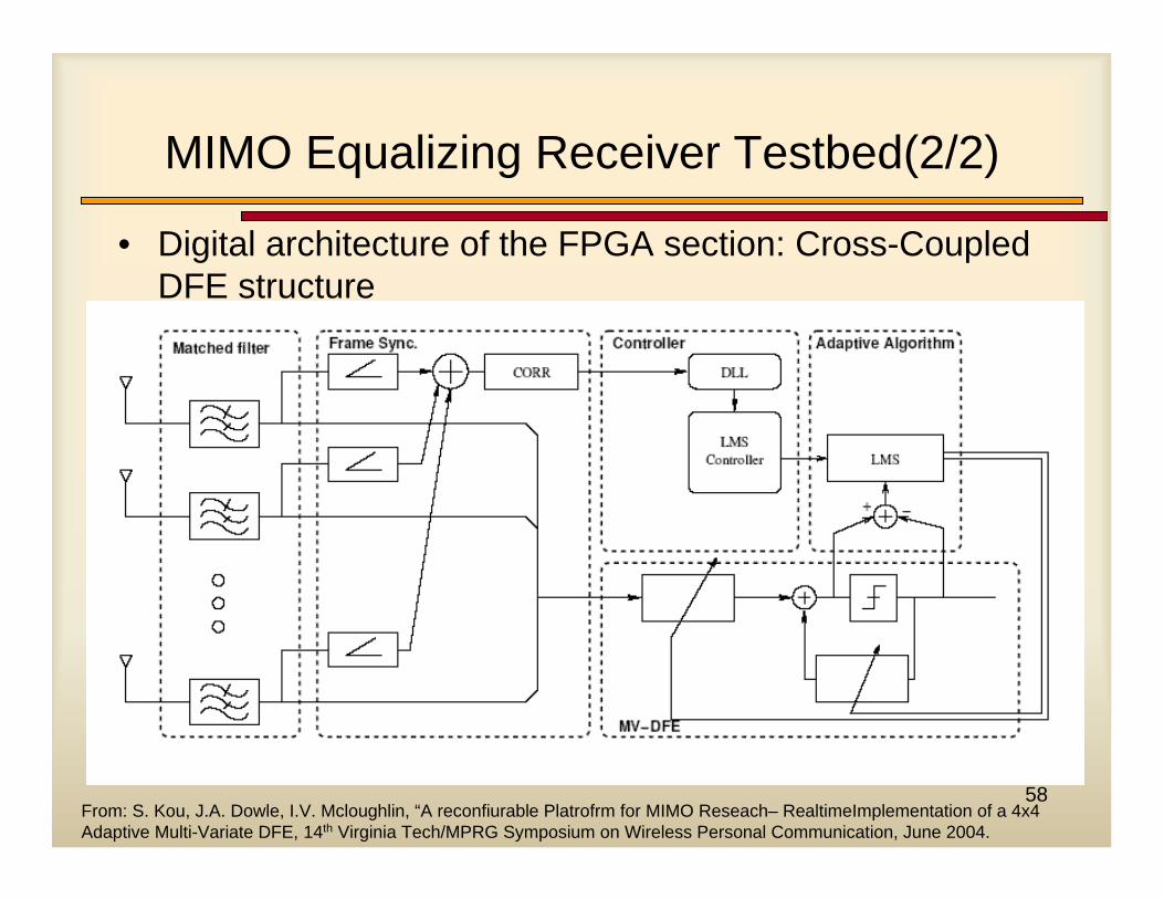
MIMO Equalizing Receiver Testbed(2/2)
• Digital architecture of the FPGA section: Cross-Coupled DFE structure
From: S. Kou, J.A. Dowle, I.V. Mcloughlin, “A reconfiurable Platrofrm for MIMO Reseach– RealtimeImplementation of a 4x4 Adaptive Multi-Variate DFE, 14th Virginia Tech/MPRG Symposium on Wireless Personal Communication, June 2004.
59
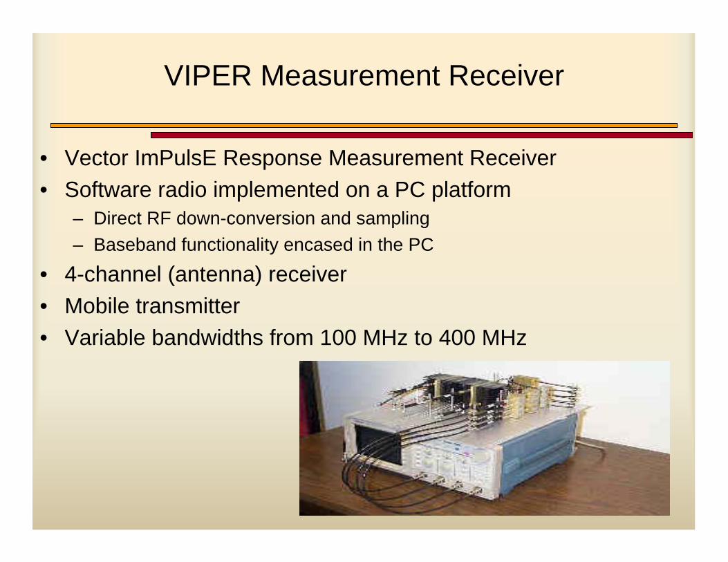
VIPER Measurement Receiver
• Vector ImPulsE Response Measurement Receiver• Software radio implemented on a PC platform
– Direct RF down-conversion and sampling– Baseband functionality encased in the PC
• 4-channel (antenna) receiver• Mobile transmitter• Variable bandwidths from 100 MHz to 400 MHz
60
Future Directions
61
Smart Antennas for 3G Systems
• 3G cellular systems can benefit from smart antenna applications – Hooks are in the standards to make this feasible.
• Better error rate performance and more capacity for WCDMA or cdma2000 with smart antenna system
• Conventional CDMA receivers coupled with smart antenna system gives rise to 2D Rake receiver.
62
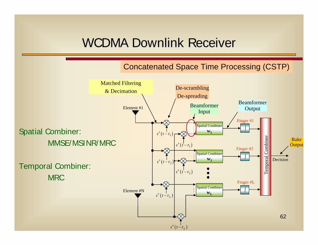
WCDMA Downlink Receiver
Element #N
( )1c t τ∗ −
Finger #1
∫
∫
∫
Tem
pora
l Com
bine
r
Decision
Spatial Combinerw1
Spatial Combinerw2
Spatial CombinerwL
Element #1
( )1c t τ∗ −
( )2c t τ∗ −
( )Lc t τ∗ −
( )2c t τ∗ −
( )Lc t τ∗ −
Finger #2
Finger #L
Matched Filtering & Decimation De-scrambling
De-spreading
BeamformerInput
BeamformerOutput
RakeOutput
Spatial Combiner: MMSE/MSINR/MRC
Temporal Combiner: MRC
Concatenated Space Time Processing (CSTP)
63
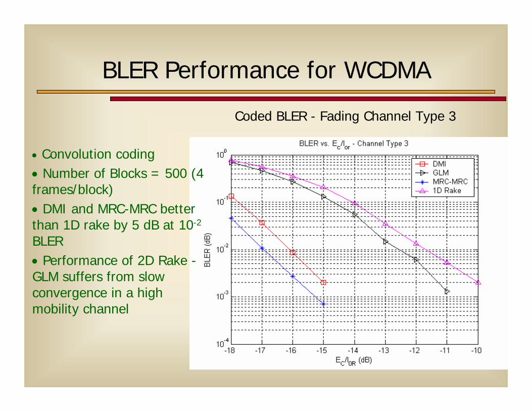
BLER Performance for WCDMA
Coded BLER - Fading Channel Type 3
• Convolution coding • Number of Blocks = 500 (4 frames/block)• DMI and MRC-MRC better than 1D rake by 5 dB at 10-2
BLER • Performance of 2D Rake -GLM suffers from slow convergence in a high mobility channel
64
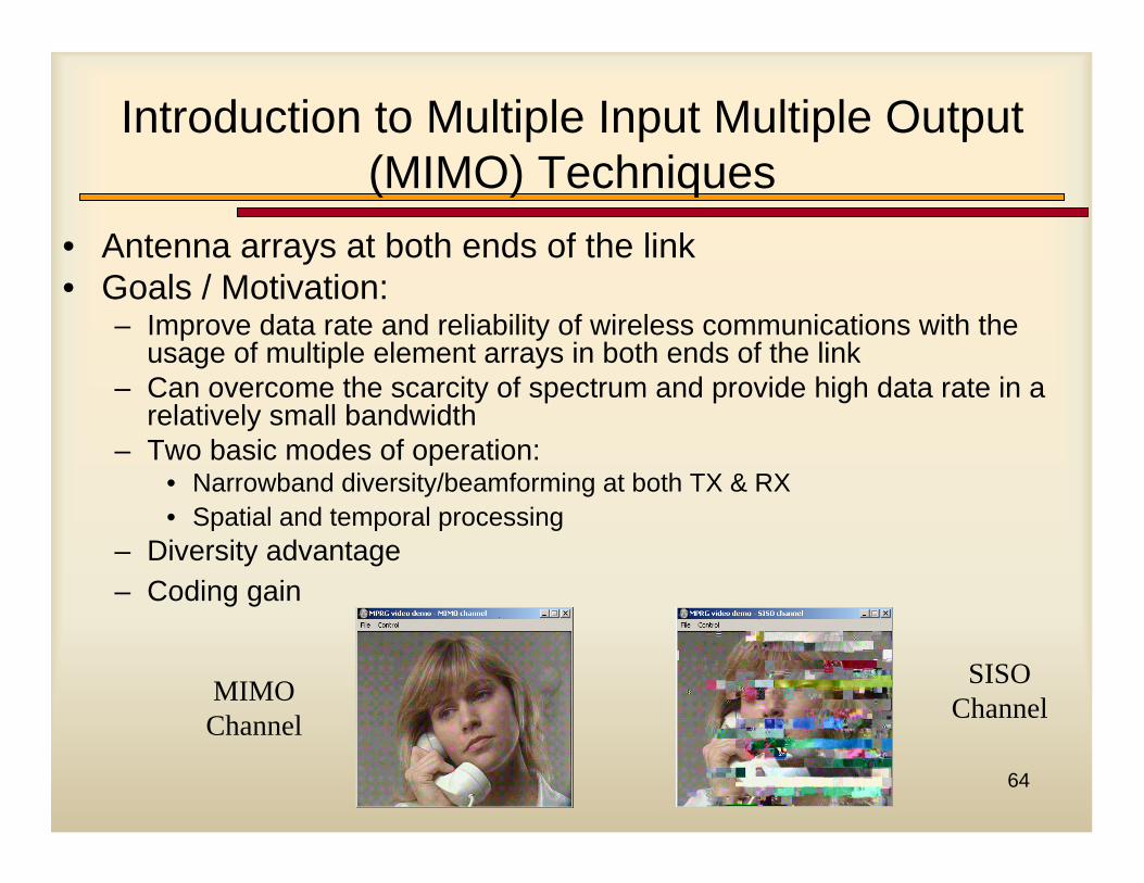
Introduction to Multiple Input Multiple Output(MIMO) Techniques
• Antenna arrays at both ends of the link• Goals / Motivation:
– Improve data rate and reliability of wireless communications with the usage of multiple element arrays in both ends of the link
– Can overcome the scarcity of spectrum and provide high data rate in a relatively small bandwidth
– Two basic modes of operation:• Narrowband diversity/beamforming at both TX & RX• Spatial and temporal processing
– Diversity advantage– Coding gain
MIMO Channel
SISO Channel
65
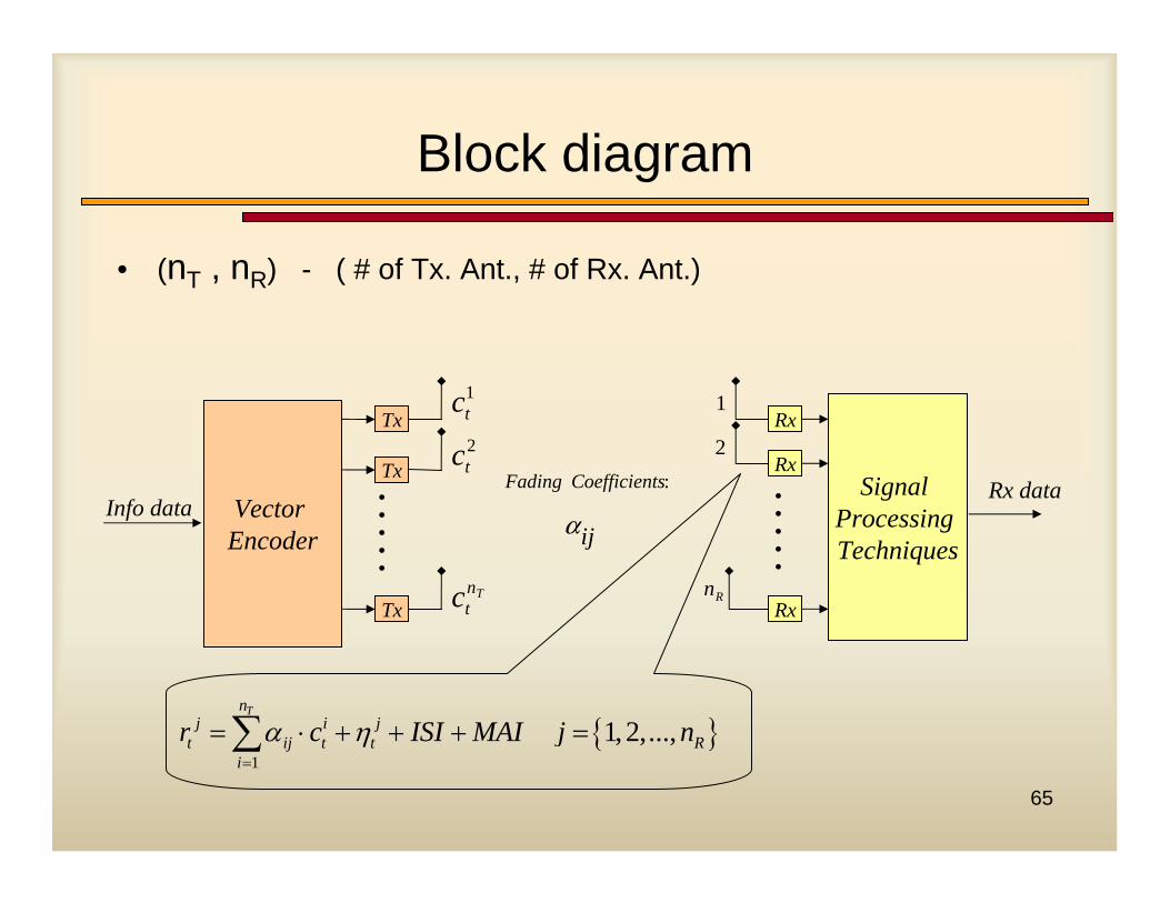
Block diagram
• (nT , nR) - ( # of Tx. Ant., # of Rx. Ant.)
Rx dataSignal Processing Techniques
Rx
Rx
Rx
•••••
1
2
nR
Info data
Tx
Tx
Tx
Vector Encoder
•••••
ct1
ct2
ctnT
Fading Coefficients
ij
:
a
{ }1
1,2,...,Tn
j i jt ij t t R
ir c ISI MAI j nα η
=
= ⋅ + + + =∑
66
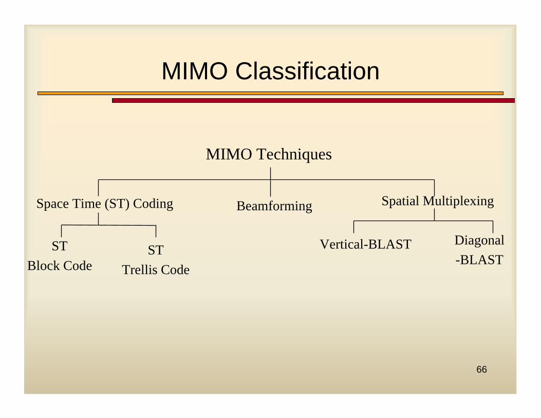
MIMO Classification
MIMO Techniques
Space Time (ST) Coding
Diagonal-BLAST
STBlock Code
STTrellis Code
Spatial Multiplexing
Vertical-BLAST
Beamforming
67
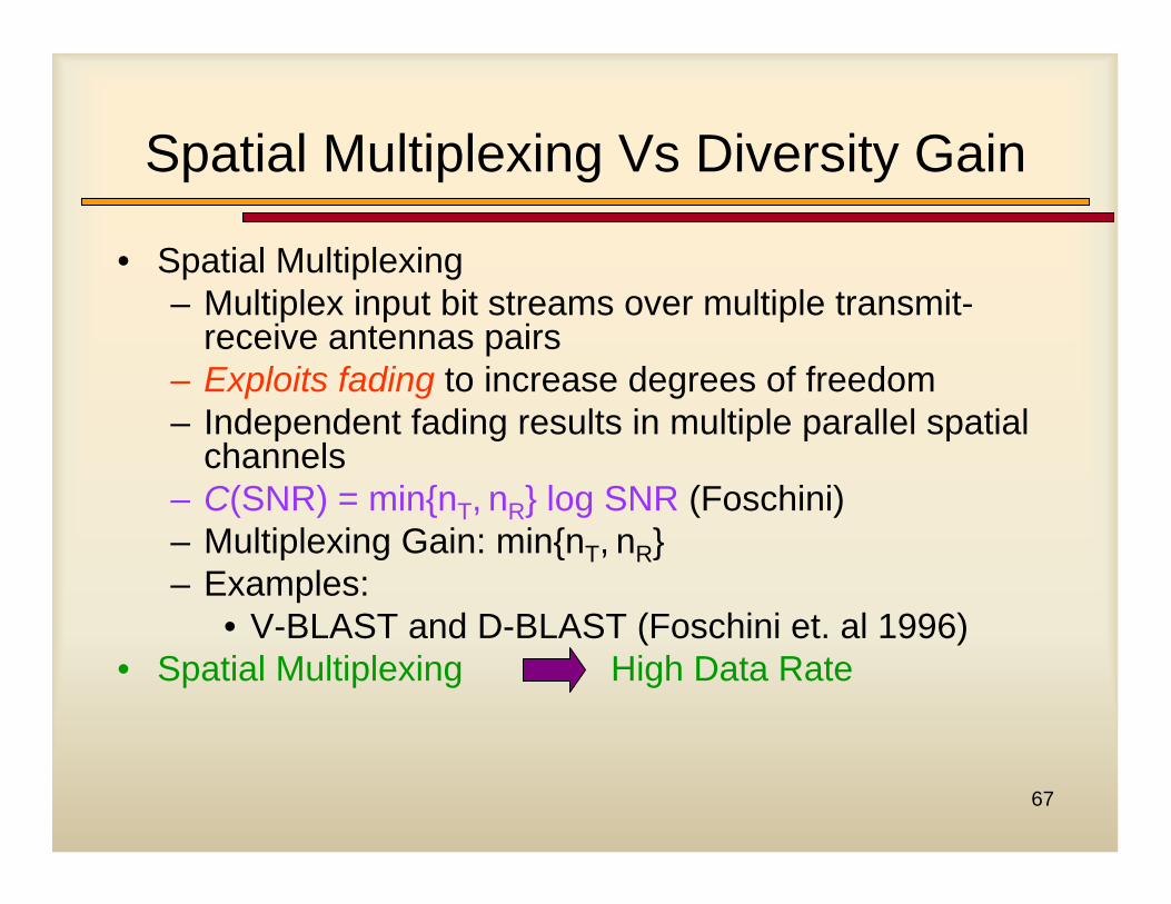
Spatial Multiplexing Vs Diversity Gain
• Spatial Multiplexing– Multiplex input bit streams over multiple transmit-
receive antennas pairs– Exploits fading to increase degrees of freedom– Independent fading results in multiple parallel spatial
channels– C(SNR) = min{nT, nR} log SNR (Foschini)– Multiplexing Gain: min{nT, nR}– Examples:
• V-BLAST and D-BLAST (Foschini et. al 1996)• Spatial Multiplexing High Data Rate
68
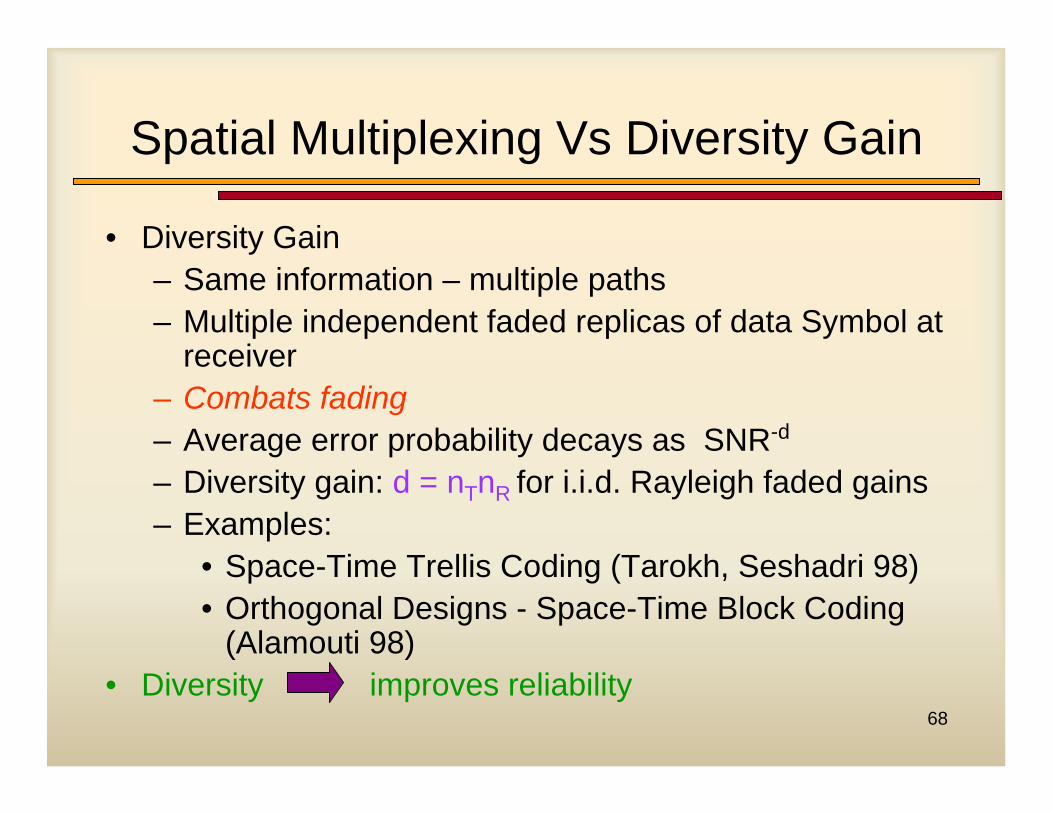
Spatial Multiplexing Vs Diversity Gain
• Diversity Gain– Same information – multiple paths– Multiple independent faded replicas of data Symbol at
receiver – Combats fading– Average error probability decays as SNR-d
– Diversity gain: d = nTnR for i.i.d. Rayleigh faded gains – Examples:
• Space-Time Trellis Coding (Tarokh, Seshadri 98)• Orthogonal Designs - Space-Time Block Coding
(Alamouti 98)• Diversity improves reliability
69
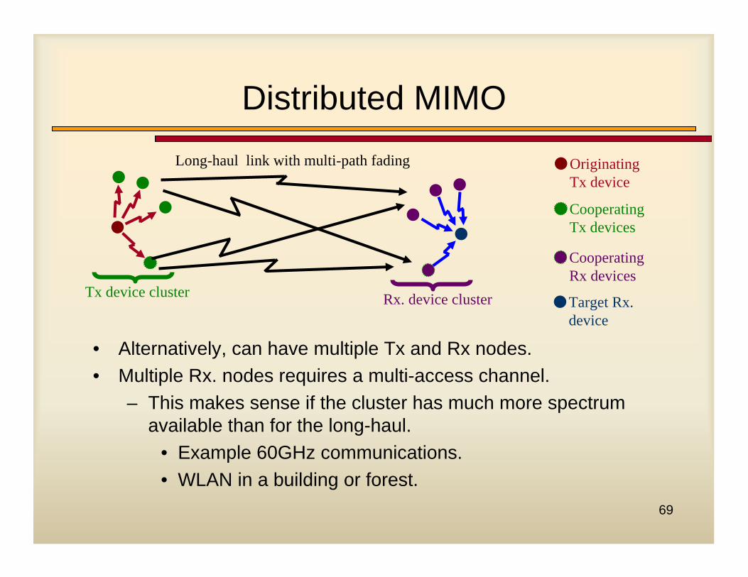
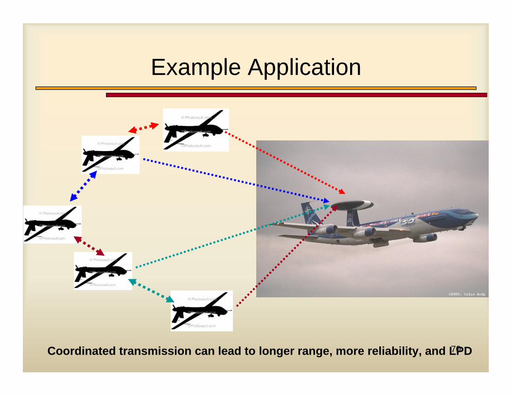
Distributed MIMO
Tx device cluster
Long-haul link with multi-path fading
Rx. device cluster
Originating Tx device
Cooperating Tx devices
Cooperating Rx devices
Target Rx. device
• Alternatively, can have multiple Tx and Rx nodes.• Multiple Rx. nodes requires a multi-access channel.
– This makes sense if the cluster has much more spectrum available than for the long-haul.
• Example 60GHz communications.• WLAN in a building or forest.
70
Example Application
Coordinated transmission can lead to longer range, more reliability, and LPD
71
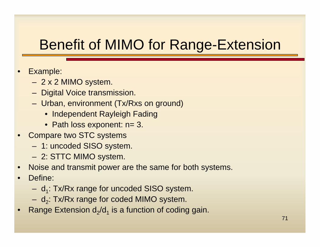
Benefit of MIMO for Range-Extension
• Example:– 2 x 2 MIMO system.– Digital Voice transmission.– Urban, environment (Tx/Rxs on ground)
• Independent Rayleigh Fading• Path loss exponent: n= 3.
• Compare two STC systems– 1: uncoded SISO system.– 2: STTC MIMO system.
• Noise and transmit power are the same for both systems.• Define:
– d1: Tx/Rx range for uncoded SISO system.– d2: Tx/Rx range for coded MIMO system.
• Range Extension d2/d1 is a function of coding gain.
72
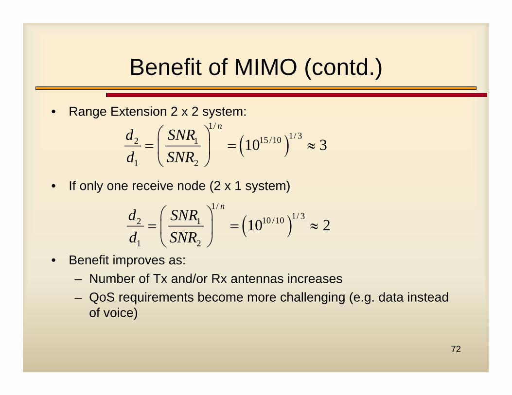
Benefit of MIMO (contd.)
• Range Extension 2 x 2 system:
• If only one receive node (2 x 1 system)
• Benefit improves as:– Number of Tx and/or Rx antennas increases– QoS requirements become more challenging (e.g. data instead
of voice)
( )1/
1/ 315 /102 1
1 2
10 3n
d SNRd SNR
⎛ ⎞= = ≈⎜ ⎟⎝ ⎠
( )1/
1/ 310 /102 1
1 2
10 2n
d SNRd SNR
⎛ ⎞= = ≈⎜ ⎟⎝ ⎠
73
Research Issues
• What Distributed MIMO applications help the war-fighter?– Answer is environment specific.– STC techniques only applicable in spatially rich multi-
path fading environments.• Can Tx/Rx timing requirements be improved through
more clever signaling at the transmitter and signal processing at the receiver?
• Which STCs best slacken requirements on carrier frequency accuracy?
74
Smart Antenna in WLAN
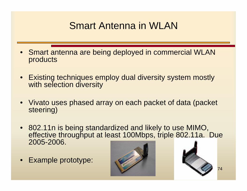
• Smart antenna are being deployed in commercial WLAN products
• Existing techniques employ dual diversity system mostly with selection diversity
• Vivato uses phased array on each packet of data (packet steering)
• 802.11n is being standardized and likely to use MIMO, effective throughput at least 100Mbps, triple 802.11a. Due 2005-2006.
• Example prototype:
75
Commercial WLAN Products with Smart Antenna Technology
• AGN1000 chipset from AIRGO includes MIMO capability– Composed of AGN100BB broadband/MAC chip and AGN100RF radio chip– MIMO system from using multiple AGN1000RF chips– Range of 300 feet with a minimum throughput of about 34Mbps for 802.11a
system – More capacity: coverage for 100-person office with just two AP vs. nine using
existing technology
• VP2200: Indoor Wi-Fi base station from VIVATO– 802.11g PHY and MAC– PacketSteering™ technology– Integrated 21dBi high-gain phased array antenna – Coverage:
• Indoor Mixed Office: 295ft/90m at 36Mbps • Warehouse: 623ft/190m at 36Mbps
76
IEEE 802.11b Air-Interface supports Smart Antenna
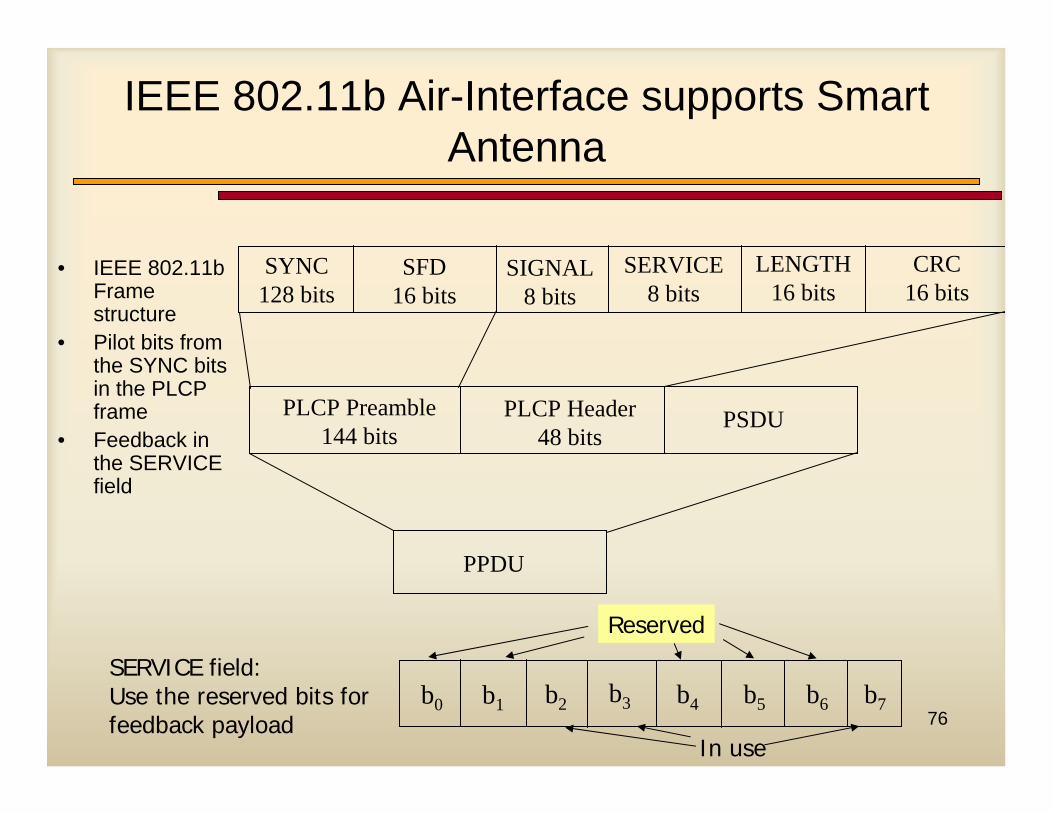
• IEEE 802.11b Frame structure
• Pilot bits from the SYNC bits in the PLCP frame
• Feedback in the SERVICE field
SYNC128 bits
SFD16 bits
SIGNAL8 bits
SERVICE8 bits
LENGTH16 bits
CRC16 bits
PLCP Preamble144 bits
PLCP Header48 bits
PSDU
PPDU
b0 b1 b2 b3 b4 b5 b6 b7
Reserved
In use
SERVICE field:Use the reserved bits for feedback payload
770 50 100 150 200 250 300
0
1
2
3
4
5
6
7
8x 10⁶
Distance
mea
n(C
)
PS-MRCSelection1 ant.
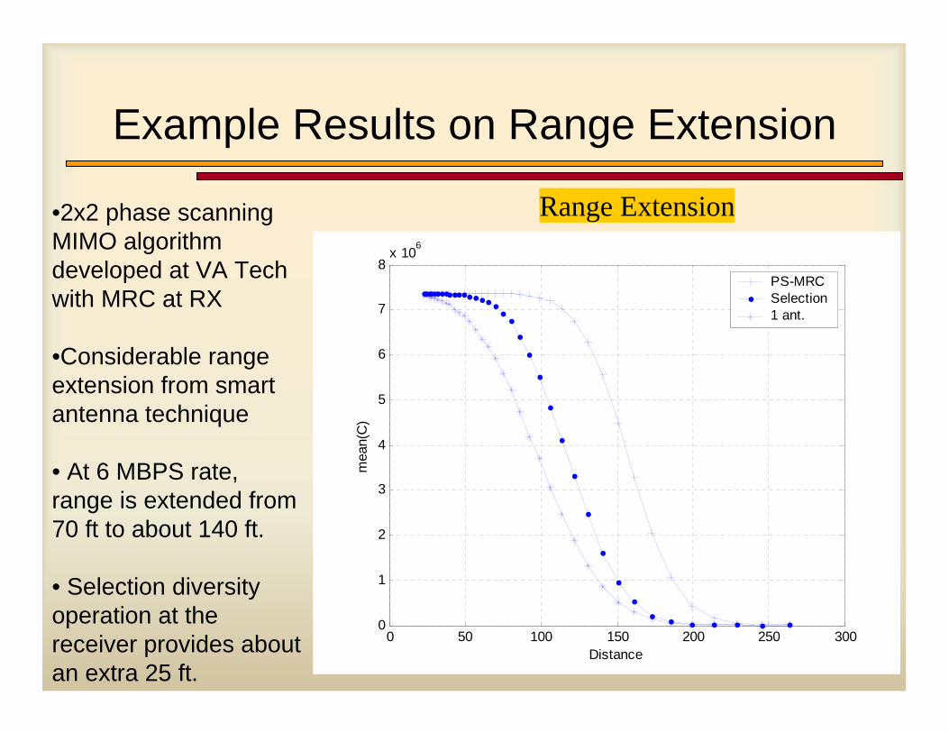
Example Results on Range Extension
Range Extension•2x2 phase scanning MIMO algorithm developed at VA Tech with MRC at RX
•Considerable range extension from smart antenna technique
• At 6 MBPS rate, range is extended from 70 ft to about 140 ft.
• Selection diversity operation at the receiver provides about an extra 25 ft.
78
IEEE802.11n: High Throughput System
• IEEE802.11 Task Group N (TGn) to develop high throughput wireless systems
• Actual throughput> 100 MBPS
• Operating spectrum: 5 GHz with BW of 20 or 40 MHz
• Main enabling technology: MIMO and OFDM
• Proposals are still being solicited, many in already
• First draft of 802.11n Specification scheduled at mid-2005
• Official proposal due by late 2006
79
Competing Proposals for 802.11n (1/2)
• Two major competitors:– TGn Sync– World Wide Spectrum Efficiency (WWISE)
• TGn Sync (not nSynch the music group!)– Consortium of Agere, Atheros, Philips, Intel, Nortel, Cisco, Sony,
Nokia, Samsung, Matsushita and Toshiba– MIMO: 2×2 (mandatory) or 4×4 (optional)– PHY data rate: 243~250 MBPS expandable to 500~600 MBPS– Spectrum: 5 GHz (mandatory) 2.4 GHz (optional)– BW: 10, 20 or 40 MHz
80
Competing Proposals for 802.11n (2/2)
• WWISE:– Consortium of Airgo, Broadcom, TI, Conexant, STMicro,
Mitsubishi and Motorola– MIMO: 4×4 – PHY data rate: probably 216 MBPS– Spectrum: 5 GHz – BW: 20 and 40 MHz
• Two groups have claims and counterclaims about their technologies
• For recent updates, follow wi-fiplanet or unstrung web sites
81
Conclusion
• Many benefits of Smart Antennas motivate SDR
• Smart antennas pose many challenges to implementation:
– Hardware: Computation, Data Movement
– Software: Lots of different configurations and hard to break into distinct components
– System Level: Network planning and performance evaluation
• Development efforts on a complete smart antenna API underway sponsored by OMG and SDR Forum
• Military as well civilian communication systems benefiting from MIMO
• Commercial products already show promise of using smart antenna technology for cellular and WLAN systems
• IEEE802.11n will provide ideal test scenario for the feasibility of commercial applications of MIMO
• Still many research issues needing to be addressed