Embed Size (px)
Citation preview
Jenway 6400-05 Ser Man Page 1 of 96
Jenway 6400/05Spectrophotometer Service Manual
Section 1 Introduction
Section 2 Quick Reference
Section 3 System Description
Section 4 Optical Description
Section 5 Electronic Description
Section 6 Software Description
Section 7 Diagnostics
Section 8 Maintenance
Section 9 Circuit Diagrams
Section 10 Assembly Diagrams
Section 11 Spare Parts List

Jenway 6400-05 Ser Man Page 2 of 96
Section 1
Introduction
1.0 Index to Sections
1.1 About This Manual
1.2 Using This Manual
1.3 Warnings & Safe Practice
1.4 Standards & Certification
1.5 Ordering Spares
1.6 Returning Items
1.7 Contacting Jenway Limited
Jenway 6400-05 Ser Man Page 3 of 96
Introduction.
1.0 Index to Sections
Section 1 – Introduction
1.0 Index to Sections1.1 About This Manual1.2 Using This Manual1.3 Warnings & Safe Practice1.4 Standards & Certification1.5 Ordering Spares1.6 Returning Items1.7 Contacting Jenway Limited
Section 2 - Quick Reference
2.0 About ‘Quick Reference’2.1 Specification2.2 Main Sub-Assemblies2.3 Power Supply Voltages2.4 Signal Levels2.5 Error Codes2.6 Special Key Functions2.7 Test Solutions
Section 3 - System Description
3.1 6400 & 6405 Comparison3.2 Sub-Assemblies3.3 Accessories3.4 Outputs
Section 4 - Optical Description
4.1 Light sources4.2 Stray Light Filters4.3 Grating4.4 Signal Detector
Jenway 6400-05 Ser Man Page 4 of 96
Section 5 - Electronic Description
5.1 Power Supplies5.2 Deuterium Lamp Supplies5.3 Detector Circuit5.4 Microprocessor and Memory Functions5.5 Accessory driver PCB
Section 6 - Software Description
6.0 Warning6.1 Start Up Routine6.2 Main Menu6.3 Menu Options
Section 7 – Diagnostics
7.1 The Diagnostics Menu7.2 Shutter and Filters7.3 Lamp Control7.4 Zero Order Cal.7.5 Calibrate Functions7.6 Wavelength Functions7.7 Channel Outputs7.8 Voltage Display7.9 Motor Position sensor
Section 8 – Maintenance
8.1 Routine Maintenance8.2 Dismantling8.3 Energy Levels8.4 Wavelength Calibration8.5 A to D Calibration8.6 D to A Calibration8.7 Performance Verification
Jenway 6400-05 Ser Man Page 5 of 96
Section 9 - Circuit Diagrams
9.10 Power Supply Schematic 640 0089.11 Power Supply Layout 640 0089.20 Deuterium Lamp Supply Schematic 640 5069.21 Deuterium Lamp Supply Layout 640 5069.30 Detector PCB Schematic 640 0099.31 Detector PCB Layout 640 0099.32 Detector PCB Schematic 640 5059.33 Detector PCB Layout 640 5059.40 Microprocessor PCB Schematic 640 0079.41 Microprocessor PCB Layout 640 0079.50 Accessory Driver PCB Schematic 642 0039.51 Accessory Driver PCB Layout 642 003
Section 10 - Assembly Diagrams
10.1 6400 Final Assembly 640 00310.2 6405 Final Assembly 640 50310.3 6400 Lower Case Assembly 640 50510.4 6405 Lower Case Assembly 640 50510.5 6400/05 Top Case Assembly 640 00510.6 6400 Optics Assembly 640 01710.7 6405 Optics Assembly 640 51710.8 6400/05 Rear Panel Assembly 640 00610.9 6400/05 Multi-cell Chamger Assembly 644 002
Section 11 – Spare Parts List
11.01 Packed Instrument11.02 Top Case Assembly11.03 Microprocessor PCB11.04 Lower Case Assembly11.05 Lamp Housing Assembly11.06 Monochromator Assembly11.07 Detector PCB11.08 Power Supply PCB11.09 Deuterium Lamp Supply PCB11.10 Rear Panel Assembly11.11 Multi-Cell Changer PCB11.12 Built-In Printer Option
Jenway 6400-05 Ser Man Page 6 of 96
1.1 About This Manual
This manual covers the service, maintenance, calibration and repairof the Jenway Ltd models 6400 and 6405 Spectrophotometers.
Throughout this manual all general statements and proceduresshould be considered to be relevant for both models. Where astatement or procedure is relevant to only one of the two models itwill be clearly stated in underlined italics, to which model itrelates, at the beginning of the relevant paragraph or section.
This manual must be used in conjunction with the InstructionManual for these models, as many of the routine maintenanceprocedures detailed in the Instruction Manual are not repeated inthis Service Manual.
1.2 Using This Manual
This manual is only for the use of Engineers and Technicians whohave successfully completed a Jenway Ltd approved ServiceTraining course on the 6400 and 6405 Spectrophotometers.
Updates to this manual will be circulated through the Jenway LtdTSI (Technical Service Information) systems and to otherregistered users of this manual. Please complete the form at the rearof this manual to register your copy for future updates.
In practice Section 2 - Quick Reference and Section 8 –Maintenance, with the Diagrams in Section 9 and 10, will be mostfrequently used, however it is good practice to read the completemanual initially and review it again periodically.
To find the information required refer to the Main Index or Indexto Sections to identify the relevant Section/page number required.
Jenway 6400-05 Ser Man Page 7 of 96
1.3 Warnings & Safe Practice
Disconnect the mains supply when any covers are removed as thereare high voltages present inside the unit that pose the risk ofelectric shock at levels that are hazardous to life!
Do not look directly at the light sources or allow the light beam tofall directly on the eyes, switch off or dim the lamps (as describedin the procedures) whenever possible and wear UV eye protectionat ALL times.
Both the UV and visible lamps get very hot when in use, alwaysallow time for them to cool down before removing them. Alwayswear cotton gloves when removing faulty lamps and replacingthem with new ones.
Finger marks, dust and condensation can quickly destroy sensitiveand expensive optical components, always wear cotton gloveswhen the optical bench is uncovered and handle any componentsby their edges only. Never touch optical surfaces. Do not removeoptical covers unless the unit is in a clean, dust and condensationfree environment.
Many of the reagents, solutions and standards used for maintenanceand calibration are corrosive or hazardous, ensure all precautionssupplied with them are followed, where there is any doubt request aMSDS (Material Safety Data Sheet) from the supplier.
These instruments can be used for analysing a broad range ofsamples, do not handle them unless you are qualified to do so.Ensure that the instrument has been correctly decontaminatedbefore working on it, specifically in areas where the instrumentmay have been used for clinical, biological, corrosive orradioactive samples.
1.4 Standards & Certification
No adjustments should be made to these instruments unless the testand measurement equipment, signal source or filters to be usedhave a current calibration certificate that is traceable to national orinternational standards and that it is known that this test equipment

Jenway 6400-05 Ser Man Page 8 of 96
is currently performing to the certified standards. All solutions andreagents should be fresh and within any stated shelf life with acertificate of analysis.
1.5 Ordering Spares
When ordering spare parts as detailed in this manual please quotethe Part Number and Description. These items should be orderedfrom the original supplier of the equipment or your local JenwayLimited Distributor.
1.6 Returning Items
Should it be necessary to return any item for any reason then thisshould be done through the original supplier of the equipment oryour local Jenway Limited Distributor.
1.7 Contacting Jenway Limited
Before contacting Jenway Limited please check our web pages forany information or updates that may be helpful to you.www.jenway.com
Emails should be sent to [email protected]
Fax: +44 1371 821083
Phone: +44 1371 820122
Please note no items can be returned (or will be accepted by)Jenway Limited without a Returns Authorisation number (RAnumber) and a completed Safety Clearance and Decontaminationcertificate.

Jenway 6400-05 Ser Man Page 9 of 96
Section 2
Quick Reference
2.0 About ‘Quick Reference’
2.1 Specification
2.2 Main Sub-Assemblies
2.3 Power Supply Voltages
2.4 Signal Levels
2.5 Error Codes
2.6 Special Key Functions
2.7 Test Solutions
Jenway 6400-05 Ser Man Page 10 of 96
2.0 About ‘Quick Reference’
This section contains a selection of the key information that isoften forgotten or difficult to find when required. Use QuickReference as a memory jogger, but for more information check outthe references to the main sections on each point.
2.1 Specification
Also see Section 1.2 of the Instruction Manual.
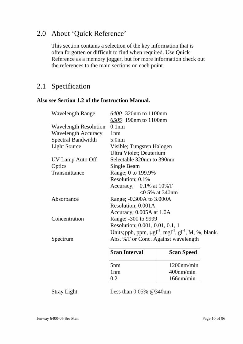
Wavelength Range 6400 320nm to 1100nm6505 190nm to 1100nm
Wavelength Resolution 0.1nmWavelength Accuracy 1nmSpectral Bandwidth 5.0nmLight Source Visible; Tungsten Halogen
Ultra Violet; DeuteriumUV Lamp Auto Off Selectable 320nm to 390nmOptics Single BeamTransmittance Range; 0 to 199.9%
Resolution; 0.1%Accuracy; 0.1% at 10%T
<0.5% at 340nmAbsorbance Range; -0.300A to 3.000A
Resolution; 0.001AAccuracy; 0.005A at 1.0A
Concentration Range; -300 to 9999Resolution; 0.001, 0.01, 0.1, 1Units; ppb, ppm, µgl-1, mgl-1, gl-1, M, %, blank.
Spectrum Abs. %T or Conc. Against wavelength
Scan Interval Scan Speed
5nm 1200nm/min1nm 400nm/min0.2 166nm/min
Stray Light Less than 0.05% @340nm

Jenway 6400-05 Ser Man Page 11 of 96
2.2 Main Sub-Assemblies
Also see Section 11 – Spare Parts
640 005 Top Case Assembly – includes the following…
640 058 Keypad640 007 Microprocessor PCB012 093 LCD Module
640 504 Lower case Assembly – includes the following…
640 510 Optics Assembly640 025 Power Supply PCB640 516 Deuterium Power supply PCB640 505 6405 Detector PCB640 009 6400 Detector PCB644 001 Multi-cell Changer with PCB060 342 Cooling Fan010 039 Torroidal Transformer
640 510 Optics Assembly – includes the following…
012 075 Tungsten Halogen lamp640 508 Deuterium Lamp650 507 Monochromator assembly032 005 12V Solenoid
Other Items – including…
016 058 1.6A Fuse for 220V supply016 007 3.15A Fuse for 110V supply017 050 Mains Switch009 123 Mains Input Socket
Jenway 6400-05 Ser Man Page 12 of 96
2.3 Power Supply Voltages
Also see Section 9 - Circuit Diagrams
Before commencing more complex fault finding it is important tocheck all the internally generated supply voltages are correct. Thefollowing list is a useful guide to help quickly check these arefunctioning correctly. Not all the points where these voltages canbe measured are given and where the voltage is stated asunregulated variations may occur. In general regulated suppliesshould vary by no more than +/-5% from their nominal value.
Tungsten Lamp Supply, 12V dc regulated and set by VR1,measure at PL5 pin 3 with respect to PL5 pin 4 on the powersupply PCB and at the terminals on the lamp base with the lampfitted.
Solenoid, Relay and Fan Supplies, 12V dc regulated and pre-set,measure at PL5 pin 1 with respect to PL5 pin 2 on the powersupply PCB and on the solenoid and fan terminals and at thecathode of D3 on the Deuterium Power supply PCB with respect to0V.
Digital Supply, 5V dc regulated and pre-set, measure across C17on the power supply PCB and across C62 on the microprocessorPCB.
Stepper Motor Drive, 30V dc unregulated, also acts asunregulated supply for all above, measure between Star3 and Star 2on power supply PCB.
LCD Supply, -18V dc regulated and pre-set, measure across theoutside pins of REG. 5 (7918) on the power supply PCB.
DAC Supply, 12V dc regulated and pre-set, measure across the toptwo pins of REG. 4 (7812) on the power supply PCB.
Deuterium PCB Supplies, 24V dc unregulated, measure acrossthe top two pins of REG1 (7812) on the Deuterium Lamp SupplyPCB. 12V dc regulated and pre-set, measure across the bottom twopins of REG. 1 (7812) on the Deuterium Lamp Supply PCB. 5V dcregulated and pre-set, measure across pins 4 and 8 of IC1 (LM311)on the Deuterium Lamp Supply PCB. 30V dc unregulated, measure
Jenway 6400-05 Ser Man Page 13 of 96
from the top of R120 (junction with R100) with respect to the topof R102 in the centre of the Deuterium Lamp Supply PCB. 14V dcregulated and pre-set, measure from the top of R101 with respect tothe top of R102 on the Deuterium Lamp Supply PCB.
Deuterium Lamp Heater, 2.5V dc (1.0V when arc has struck)regulated and pre-set, measure across R9 on the Deuterium LampSupply PCB or between the two blue wires on pins 2 and 3 of theDeuterium Lamp Socket (SK1).
Deuterium Lamp Arc, 170V dc pulsed to strike, 300mA at 70V(Temperature Compensated) when arc has struck. Measure acrossR119 on the Deuterium Lamp Supply PCB and between pins 1 and3 on the Deuterium Lamp Socket (SK1).
Detector PCB Supplies, 5Vdc regulated and pre-set, measureacross D2 on the Detector PCB. –5V dc regulated and pre-set,measure across D3 on the Detector PCB.
Sampling Accessory PCB, 5Vdc regulated and pre-set, measureacross C15. 15V dc regulated and pre-set, measure between R18 atjunction with REG 2 and junction of D1 and C22.
2.4 Signal Levels
Also see Section 7.02 - Shutter and Filters and 8.3 – EnergyLevels
All analogue signal processing is dealt with on the Detector PCB.Relevant signals from this PCB are shown in the DiagnosticsScreen as a Voltage, in mV, and CH0, CH1 and CH2 in ‘counts’directly from the A to D converter. For more detailed definitions ofthese terms see Section 5.3 - Detector Circuit and Section 7.01 –The Diagnostics Menu, Section 7.02 – Voltage Display and Section7.03 Channel Outputs.
The Voltage Display can be used to check lamp energy (ageing),the correct functioning of the IR Stray Light filter and the UV StrayLight Filter as well as the Dark Shutter.
Jenway 6400-05 Ser Man Page 14 of 96
6405U V Energy, Set wavelength to 190nm, Dark Shutter open, IRstray light filter closed, UV second order stray light filter open;Voltage Display must be greater than 20mV.
6400/6405Visible Energy, Set wavelength to 805nm, Dark Shutter open, IRstray light filter open, UV second order stray light filter closed;Voltage Display must be greater than 1000mV and less than3600mV.
Dark Current, Set wavelength to 320nm, Dark Shutter closed, IRstray light filter closed, UV second order stray light filter open;Voltage Display should be zero +/- 6mV.
320nm Output, Set wavelength to 320nm, UV lamp off, DarkShutter open, IR stray light filter closed, UV second order straylight filter open; Voltage Display must be greater than 17mV.
2.5 Error Codes
See also Section 8 of the Instruction Manual
A number of dialogue boxes are generated with messages relatingto fault conditions, these are detailed below with a brief descriptionof some of the most common causes for these errors.
Self Test Failure, If any of the power-on self tests have been failedthis message is displayed. The check box for the specific test thathas failed will be marked with a cross (X).
Warning – Operating Parameters Corrupt Restoring ToDefault Settings, This warning message indicates that the contentsof the non-volatile memory has been corrupted. This may be due toa failure of the battery back up, or that the battery has becomedischarge if the instrument has not been used for several months. Itmay also occur by switching off, or a power interruption, during asave or retrieve operation. Acceptance of the warning by pressingthe enter key will enable normal operation to continue with thedefault settings loaded, all previously stored settings will be lost.

Jenway 6400-05 Ser Man Page 15 of 96
Dark Level Too High, Sample chamber cover left open duringstart up tests or a calibration, dark shutter stuck open, solenoid orsolenoid drive/connections faulty, Detector PCB failure.
Light Level Too Low, Blank too optically dense, plastic or glasscuvettes used in the UV range, miss-alignment of cell carriage,wrong lamps fitted, lamps miss-aligned, dark shutter stuck closed.This may also be due to the contamination of optical surfaces.
Unable To Detect Peak Level, Cuvette left in sample chamberduring start up tests, miss-aligned cell carriage, wrong lamps fitted,miss-aligned lamps or lamp carriage, contaminated opticalcomponent.
Error, Unable to Acquire Dark Level, This message will beshown if the dark level cannot be achieved during the start up tests,possible causes will be similar to those listed under ‘Dark level toohigh’ above.
Fatal Error, Calibration Failure, Grating position opto-couplerfaulty or connections broken/intermittent, incorrect wavelengthcalibration carried out, check connections to stepper motor andcheck PL3 connections on Power Supply PCB.
Invalid Slope Range, The standard used to calibrate aconcentration measurement cannot give the standard value entered,this can be because the standard is too optically dense or toosimilar to the blank. Alternatively the incorrect standard value mayhave been entered.
Warning Tungsten Lamp Failure, Tungsten lamp filamentbroken, wrong type of tungsten lamp fitted, no tungsten lampfitted, cables to lamp base broken/damaged, check SK4 on powersupply PCB.
Warning Deuterium Lamp Failure, Deuterium lamp faulty, cabledisconnected, 6400 set up as 6405.
Fatal Error, System Calibration Data Failure, During the startup test sequence the microprocessor has been unable to detect thecalibration data stored in the E2PROM on the Detector PCB. Thismay indicate a faulty Detector PCB or that the connections to theDetector PCB are not made or are intermittent.

Jenway 6400-05 Ser Man Page 16 of 96
2.6 Special Key Functions
There are a number of special key functions for use by trainedengineers, do not use them unless you are fully conversant with allthe procedures these invoke.
Power On Reset, Hold the <Enter> key depressed while turningon the power. This clears the operator set parameters held in non-volatile memory and is useful in correcting many softwareconflicts.
Skip Power On Tests, Hold the decimal point <.> key depressedwhile turning the power on, this function must only be used forfault finding procedures, taking readings on an instrument startedin this way will produce unpredictable errors.
Diagnostics Mode, Hold the right arrow <>> key depressed whileturning the power on, do not enter this mode unless you have thecorrect training and equipment, making adjustments here canpermanently damage the instrument.
2.7 Test Solutions
1. Holmium Perchlorate – 5% w/v solution of Holmium Oxide in 1.4NPerchloric acid, this will give absorbance maxima at 241.0, 278.1,287.0, 361.4, 416.1, 451.1, 485.3, 536.5 and 640.5nm.
2. Potassium Dichromate – 100.0mg/l in 0.005M Sulphuric Acid (use theSulphuric Acid as the blank). This will give Absorbance values of1.071 at 350nm, 0.484 at 313nm, 1.444 at 257nm, 1.242 at 235.Potassium Dichromate – 50.0mg/l in 0.005M Sulphuric Acid (use theSulphuric Acid as the blank). This will give Absorbance values of0.536 at 350nm, 0.242 at 313nm, 0.722 at 257nm, 0.621 at 235.
3. Sodium Nitrate – 50g/l in deionised water, should give less than 0.1%transmittance at 340nm.Sodium Iodide – 10g/l in deionised water, should give less than 0.1%transmittance at 220nm.
All these solutions are hazardous and the manufacturer/suppliers safetyprecautions should be carefully followed at all times in preparation, useand storage.

Jenway 6400-05 Ser Man Page 17 of 96
Section 3
System Description
3.1 6400 & 6405 Comparison
3.2 Sub-Assemblies
3.3 Accessories
3.4 Outputs
Jenway 6400-05 Ser Man Page 18 of 96
3.1 6400 & 6405 Comparison
The models 6400 and 6405 share the majority of common sub-assemblies. However the 6400 is not fitted with the DeuteriumLamp power Supply PCB and of course the Deuterium Lamp itself.
Because of this the optics and monochromator are slightlydifferent, but in arrangement only.
The Detector, hence Detector PCB is specific to each model,640 009 for the 6400 and 640 505 for the 6405. (See Section 5.3Detector Circuit).
3.2 Sub-Assemblies
The 6400 and 6405 can easily be broken down into sub-assembliesfor the purposes of repair or replacement. All the PCBs are easilyremoved, see Section 8.2 – Dismantling. The monochromator andlamp carriage, which together contain most of the opticalcomponents are both replaceable sub-assemblies. There are anumber of sampling accessories that can be fitted into the samplecompartment and removed with very little dismantling.
See Section 2.2 for details of the main sub-assemblies and Section11 for details of other spare parts. The following paragraph lists thesampling accessories available.
3.3 Accessories
The following sampling and temperature control accessories areavailable, where necessary additional service information for theseaccessories is available on request. The development of othersampling accessories is continuous, please check current brochuresor www.jenway.com for up-to-date information.
644 001 Motorised Eight Position Cell Holder644 003 Rack to Hold 10mm Cells for Above649 001 Water Jacketed Cell Holder as Above648 001 Water Jacketed Single Cell Holder642 001 Sipper Pump647 001 Temperature Controlled Sipper Pump
Jenway 6400-05 Ser Man Page 19 of 96
645 001 Vacuum Pump643 001 Peltier Temperature Control System646 002 Universal Test Tube Holder630 003 20 to100mm Single Cell Holder
Other accessories include:
641 001 Internal 40 Column Printer542 009 Interface Cable Kit640 133 Dust Cover
3.4 Outputs
The 6400 and 6405 have both analogue and RS232 outputs.
Details of the level of the analogue output for the different rangesthat may be selected on the instruments is given in Section 6.3 ofthe Instruction Manual.
Pin configuration for the RS232 socket is given in Section 6.2 ofthe Instruction Manual. Section 6.1 of the Instruction Manual givesdetails of the various ASCII codes that may be transmitted to the6400 or 6405 to remotely control them.
Jenway 6400-05 Ser Man Page 20 of 96
Section 4
Optical Description
4.1 Light Sources
4.2 Stray Light Filters
4.3 Grating
4.4 Signal Detector
Jenway 6400-05 Ser Man Page 21 of 96
4.1 Light Sources
The model 6400 uses a single Tungsten Halogen lamp to cover itsfull wavelength range of 320nm to 1100nm.
The model 6405 uses the same Tungsten Halogen lamp with a ‘seethrough’ Deuterium lamp to cover its wavelength range of 190nmto 1100nm.
The use of the ‘see through’ Deuterium lamp enables both lamps tobe on in the low energy area, found at high UV wavelengths,reducing the typical energy dip. It also eliminates the spikescreated in systems that use a lamp changeover mirror.
It is still possible to switch off the Deuterium lamp to save lamplife when working only in the visible region and the ‘switch off’point can be selected between 320nm and 390nm.
The lamps are both pre-aligned and can be simply replaced byremoving the lamp carriage after the lamp access panel has beenremoved. See Sections 4.2 and 4.3 of the Instruction Manual.
4.2 Stray Light Filters
6405 The 6405 uses three stray light filters.
The first filter is located between the Tungsten and Deuteriumlamps. This filter is solenoid actuated and is switched into the lightpath between 0nm and 390nm to eliminate unwanted Infra Redlight. (Part number 035 105)
The second filter is located after the Deuterium lamp, inside themonochromator, is solenoid actuated and is switched into the lightpath between 390nm and 1100nm to eliminate unwanted UV light.(Part number 035 109)
The third filter is mechanically linked to the grating mount and isin the light path between 550nm and 1100nm to eliminateunwanted second order diffraction. (Part number 035 036)
Jenway 6400-05 Ser Man Page 22 of 96
6400 The 6400 uses two stray light filters
The first filter is located after the tungsten lamp inside themonochromator. This filter is solenoid actuated and is switchedinto the light path between 0nm and 390nm to eliminate unwantedInfra Red light. (Part number 035 106)
The second filter is mechanically linked to the grating mount and isin the light path between 550nm and 1100nm to eliminateunwanted second order diffraction. (Part number 035 036)
4.3 Grating
The 6400 and 6405 optics use the same grating, this is a concaveholographic grating with 1200 lines per mm
The grating is directly coupled to the stepper motor, which is undermicroprocessor control, thus reducing backlash and mechanicalerrors.
4.4 Signal Detector
Photo diode detectors are used on both models; an S1133 type onthe 6400 and the UV enhanced version S1337 on the 6405.
The detector PCB carries out all the analogue signal processing andeach one carries its own calibration data stored in an on-boardE2PROM. The detector PCB also communicates with themicroprocessor to set the instrument for UV/visible (6405) orvisible (6400) operation. For more information see Section 5.3 –Detector Circuit.
Jenway 6400-05 Ser Man Page 23 of 96
Section 5
Electronic Description
5.1 Power Supplies
5.2 Deuterium Lamp Supplies
5.3 Detector Circuit
5.4 Microprocessor and Memory Functions
5.5 Accessory Driver PCB
Jenway 6400-05 Ser Man Page 24 of 96
5.1 Power Supplies
The ac mains supply is reduced by the torroidal transformer givingfive low voltage outputs from the secondary windings. Eachsecondary is protected by a re-setable fuse which will go opencircuit when excess current is drawn, when the current is reducedto normal the fuse will re-set. A 5A fuse is fitted for the 20Vwinding, 0.2A fuses for the 15V and 9V windings and 2.5A fusesfor the 16V and 18V windings.
The 20V ac output from the transformer is rectified by D1; the 30Vdc output from this rectifier is used as the input to three L4960switch mode regulators. (REG1, REG 2 and REG 3).
Tungsten Lamp Supply, The output of the switch mode regulatorREG 3 is set to 12V dc by VR1. The 10K NTC thermistor (R22)adds temperature compensation to this output voltage reducingwarm up time and thermal drift. The 12V output can be reduced to5.1V by a logic ‘1’ on the gate of TR5 switching TR3. Thishappens during the start up tests to reduce the light level foraccurate zero order detection, it can also be manually instigated bypressing key 5 when in the Diagnostics Menu. Increased currentflow through the 0V return from the lamp is detected by TR1 toconfirm that the lamp is functioning (i.e. the lamp filament isintact).
Solenoid, Relay and Fan Supply, The output of the switch moderegulator REG2 is pre-set to 12V. The output to the two fans is viaPL12 pin 1 and 2 and PL5 pins 1 and 2.
The output to solenoid 1 (Dark Shutter) is via PL1 pin 1 and it isswitched on when SK4 pin 27 goes high, this switches TR2 tomake PL1 pin 4 low.
The output to solenoid 2 (IR Stray Light Filter) is via PL1 pin 2and it is switched on when SK4 pin 22 goes high, this switchesTR4 to make PL1 pin 5 low.
The output to solenoid 3 (UV (Second Order) Stray Light Filter) isvia PL1 pin 3 and it is switched on when SK4 pin 14 goes high,this switches TR6 to make PL1 pin 6 low.
Jenway 6400-05 Ser Man Page 25 of 96
The 12V supply to the UV strike relay goes via SK9/PL9 pin 6 tothe Deuterium Lamp supply PCB where it is tracked to the relay.The relay is switched when SK4 pin 23 goes high switching TR7 tomake SK9/PL9 pin 7 low.
5V Digital Supply, The output of the switch mode regulator REG1 is pre-set to 5V and the output is distributed via SK4 pin 1.
The 15V secondary winding of the transformer is half waverectified by D5 and D6 to generate the following supplies:
LCD and DAC Supplies, The 7918, -18V regulator gives a -18Voutput on SK4 pin 28 this is then routed to the LCD supply. The7812, 12V regulator gives a 12V output. This is tracked to IC200,and the associated circuitry that makes up the DAC. Calibrationdata for the DAC is stored in the E2PROM IC201.
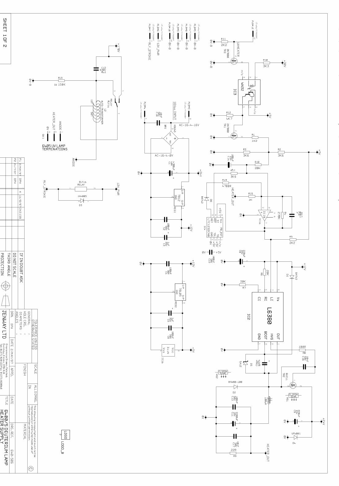
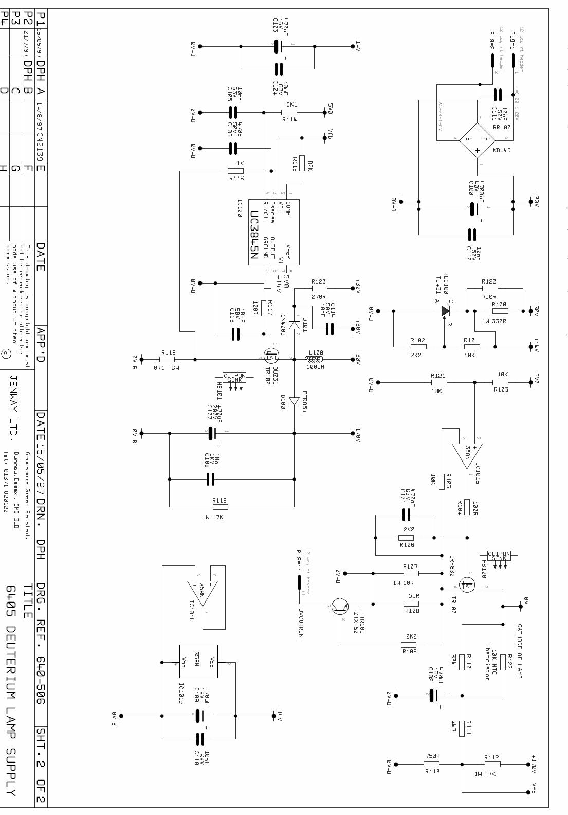
5.2 Deuterium Lamp Supplies
In the Deuterium lamp the gas is initially heated by an elementpowered at 2.5V. An arc is struck between the Anode and cathodeat around 750V, when the arc is established it is maintained at aconstant current of 300mA at 70V while the heater voltage isreduced to 1V.
A local supply of 12V dc is generated from the 16V ac winding ofthe transformer. This 12V supply is then used to generate aregulated 5V supply.
The 20V ac winding of the transformer is used to generate anunregulated 30V supply.
The boost regulator circuit based around the pulse width modulatorIC100 uses this 30V to generate a 170V supply. This supply is thenswitched across the auto-transformer L2 by relay RLY1a toincrease this voltage to about 750V, sufficient to strike the arc.
When the arc has been struck IC101a and TR100 maintain thecurrent at 300mA. Power is kept to a minimum at varyingtemperatures by R122, a 10K NTC Thermistor. TR101 detects thecurrent flow and an output is sent to the microprocessor via PL9pin 11.
Jenway 6400-05 Ser Man Page 26 of 96
The heater voltage is generated by the high side driver IC2, thiswill be 2.5V until a signal from the microprocessor, isolated by IC3switches the comparator IC1a, which in turn reduces the heatervoltage to 1V. The watchdog IC4 ensures that the comparator iscontinually updated.
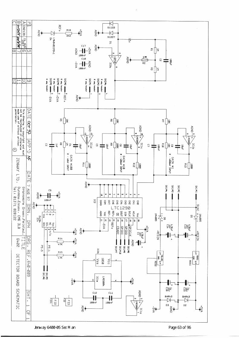
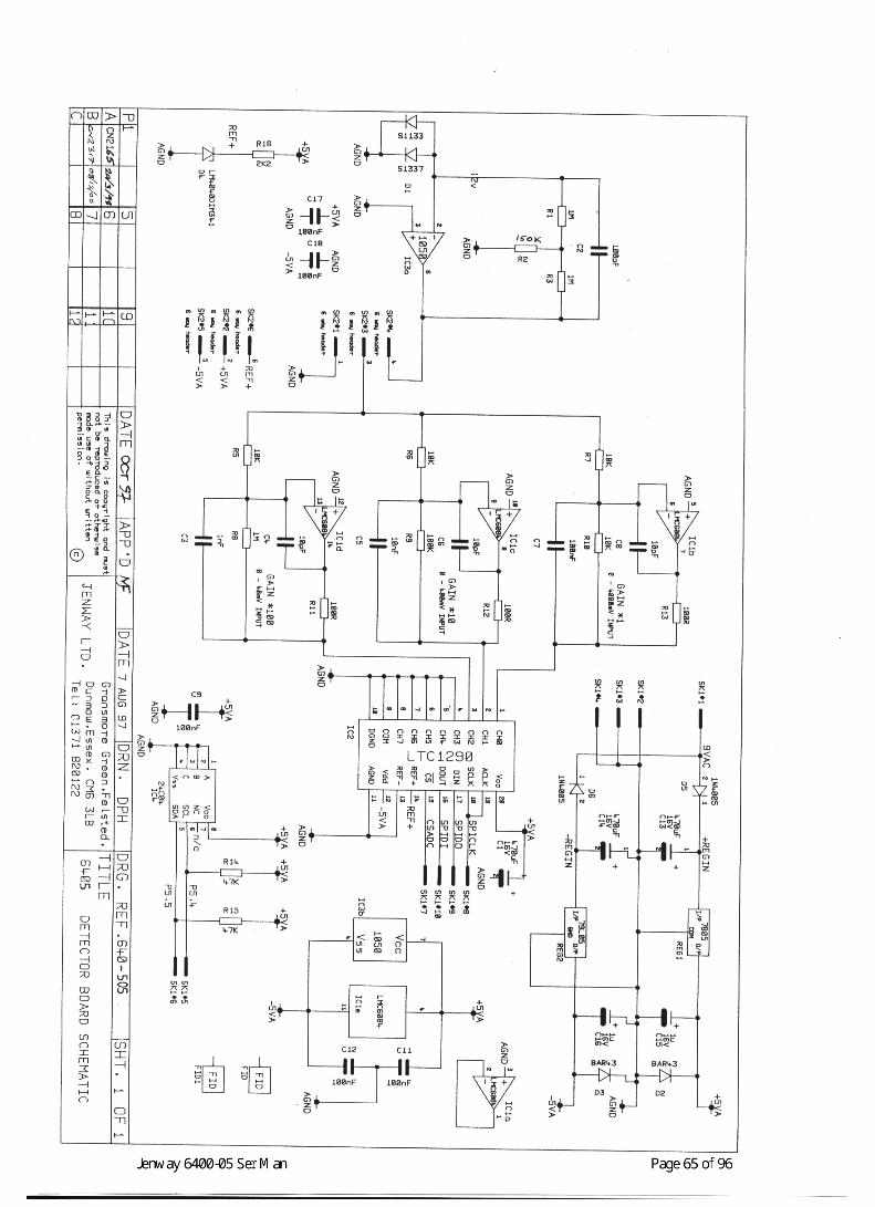
5.3 Detector Circuit
Detectors and AmplifiersThe detector PCB’s (640 009 for the 6400 and 640 505 for the6405) are identical except for the photodiode detector and the pre-set programming that determines whether the unit is either a 6400or 6405. The photodiodes fitted will be an S1133 for the Model6400 or the UV enhanced version S1337 for the 6405.
The current through the detector is proportional to the incidentlight. IC3a acts as a current to voltage converter, the gain being setby the feedback resistors in the T network.
IC1 is a low pass filter that attenuates frequencies of 50Hz orgreater from the signal. In normal operation pins 3 and 4 of SK2are linked so the signal passes to the three remaining amplifiers ofIC1. IC1b is set for unity gain, IC1c has a gain of 10 and IC1d again of 100.
A to D ConversionEach of these amplified signals then pass into the first threechannels (CH0 to CH2) of an 8 channel, 12 bit, serial, A to Dconverter.
All three channels are converted and the microprocessor selects thechannel that gives the best resolution without reaching saturation(32767 counts). In effect this means CH2 will be selected for inputsup to 40mV, CH1 for inputs up to 400mV and CH0 for inputs up to4.0V.
The A to d converter requires a reference voltage of 4.096V whichis generated from the –5V rail by D4, this is inverted to a positivevalue by IC5d and fed to pin 14, Ref+, of the A to D converter,IC2.The E2PROM, IC4, maintains calibration data for the PCB, seeSection 8.6 - A to D Calibration as well as programming the unitfor visible (6400) or UV/visible (6405) operation.
Jenway 6400-05 Ser Man Page 27 of 96
5.4 Microprocessor and Memory Functions
EPROMIC3 is a 256K byte EPROM that contains the software code for theexecutable programme. Its label will show the software versionnumber and date it was programmed.
RAMUser Variables that are input during operation are stored in batterybacked RAM (IC1 supported by Bat 1). User variables are datagenerated from operator input for values such as wavelength limitsfor scanning, calibration data for concentration and quantitationmeasurements, run time for kinetics etc, etc. These values can bere-set to their factory set default values by the Reset Parametersfunction in the Instrument Setup Menu or by performing a poweron re-set, see Section 2.6, Special Key Functions.
PeripheralsActive time and date information is generated and stored by thereal time clock IC18, the data stored here can be re-set through the‘Clock Setup’ function in the ‘Instrument Setup’ menu.
IC2 is the ‘watchdog’, which monitors the supplies and back upbattery. It re-sets the instrument if these fall below critical levels.
The optional internal printer is driven directly from themicroprocessor via PL3. Under no circumstances should thisdevice be connected or disconnected with power supplied to theinstrument.
MicrocontrollerIC5 is the microcontroller, a Hitachi H8/3002 device running at12MHz. This integrates system support functions together with anH8/300H CPU core with a 32 bit internal architecture. Of thesystem support functions the internal timer (ITU), serialcommunications interface (SCI), A to D converter and I/O ports areused to reduce the number of external components required.
Display Drive and ContrastIC4 and IC6 are used to reduce the clock speed for running theLCD. The LCD contrast is pre-set in manufacture by VR1 andtemperature compensated by TR1 at 10mV per degree C. Operator

Jenway 6400-05 Ser Man Page 28 of 96
adjustment of the contrast is through the software via the digitalpotentiometer IC13, this adjusts the output of IC11a to valuesaround –10V at VLCD on PL1.
Keypad and RS232 InterfaceThe keypad interface uses the A to D converter built into themicrocontroller. The eight resistors, R21 to R28 form a potentialdivider from the +5V to 0V levels. This gives 7 discreet voltagelevels on pins 4 to 10 of PL4. These form a matrix with the 3keypad input ports (KEYINP0, KEYINP1, KEYINP2) on PL4 pins1,2 and 3. In this way up to 21 keys can be recognised by a specificvoltage on its relevant port.
The RS232 output is generated by IC8 and routed via PL2 to thepower supply PCB and hence to the rear panel socket.
5.5 Accessory Driver PCB
Both 6400 and 6405 models can be fitted with the optionalAccessory Driver PCB. This is capable of driving all internalsampling accessories and makes available supplies and controls fordriving external modules such as the peltier/sipper accessory.
Local supplies of 5V and 12V are generated from the 18V acwinding of the transformer.
The Accessory Driver PCB has it’s own on-board micro-controllerwhich has a permanent master/slave relationship with the mainmicroprocessor.
The Accessory Driver is on the Serial Peripheral Interface Bus(SPIBus) and is selected by the CSACC line.
The on-board E2PROM maintains calibration data for the fittedaccessory. In the case of the multi-cell changer this includes thenumber of steps on the stepper motor from the sensor vane to thefirst sample position. This will vary from accessory to accessory,so the PCB and mechanical assembly must be treated as a matchedpair in this instance.

Jenway 6400-05 Ser Man Page 29 of 96
Section 6
Software Description
6.0 Warning
6.1 Start Up Routine
6.2 Main Menu
6.3 Menu Options
Jenway 6400-05 Ser Man Page 30 of 96
6.0 Warning
This section gives an overview of the software modules, it is notmeant to be a detailed analysis of the software routines or code.Also it must not be treated as a substitute Instruction Manual, itspurpose is to enable basic navigation through the operational andset up modes sufficient to verify basic operation.
6.1 Start Up Routine
When the power to the unit is switched on a self-test routine isactivated. This routine can be bypassed through the special keyfunctions, see Section 2.6, this mode of operation must only beused for fault finding and repair as the unit will not have beenthrough the necessary calibration and check routines to guaranteethe accuracy of any readings. During the start-up tests thefollowing parameters are checked and must pass before operationcan continue:
System Test: - This test checks the status of the user variablesstored in battery backed RAM and the calibration data stored in theE2PROM on the Detector PCB
This test will be failed following a power on re-set using the shortcut keys. This is not a fatal error but a warning message will advisethat ‘Default operating parameters have now been loaded’ and willrequire acceptance before continuing.
This test will also be failed if the calibration data has beencorrupted, in this case a warning message ‘FATAL ERROR.System Calibration data failure,’ will be displayed. This failure willbe due to a faulty Detector PCB or due to broken/damagedconnections to the Detector PCB.
Tungsten Lamp Test: - This test checks for current flow throughthe tungsten (visible) lamp filament. This test will be failed if thelamp filament is broken (bulb blown), if the lamp is not fitted, if anincorrect lamp is fitted, if connections to the lamp base are faultyor broken or if the 12V supply to the lamp is faulty (power supplyPCB).
Jenway 6400-05 Ser Man Page 31 of 96
Dark Level Test: - This test checks that the output of the detectoris below a threshold level when there is no light falling on it. Thistest will be failed if the sample chamber lid is left open during thestart up routine, if the dark shutter (solenoid 1) is faulty (electricalor mechanical) or if the Detector or Detector PCB is faulty.
Wavelength Calibration: - This test checks for the zero order(white) light that is reflected through the sample chamber when thegrating is in a position where it acts as a mirror. Each time the unitis switched on this position is used as a physical reference pointagainst which the stored wavelength calibration data is applied.
This test is carried out in the following manner; the microprocessorinstructs the grating to drive anticlockwise by 1250nm. This shouldensure that the vane attached to the grating mount breaks the lightpath of the optocoupler mounted on the monochromator base plate.If it does not receive a signal from the optocoupler then an errormessage ‘Fatal Error, Calibration Failure’ is returned when themotor stops.
In correct operation a signal is returned when the vane reaches theoptocoupler. Then the microprocessor instructs the grating to rotateclockwise in 1nm steps for 200nm, or until a signal greater than200mV is returned from the detector (this level, with the lampdimmed can only be produced by the white zero order light). If this200mV level can not be achieved then the grating stops afterhaving rotated the 200nm and an error message ‘Unable to AcquirePeak Level’ is returned.
In correct operation when this 200mV level is detected the gratingrotates in the same direction for a further 200nm but in 0.2nmsteps. A wavelength/output table is generated as the outputincreases, and then decreases back to 200mv. If the grating rotatesthe full 200nm without the output falling back to 200mV then theerror code ‘Unable to Acquire Peak Level’ is returned.
In correct operation when the 200mV level on the other side of thepeak is reached, the actual peak wavelength level is picked fromthe table. This point is then set as the zero order level and thestored calibration data is referenced against this point.
Jenway 6400-05 Ser Man Page 32 of 96
This test will be failed if samples or cuvettes etc are left in thesample compartment during the start up routine, if the sampleholder or sampling device in the sample chamber is incorrectlyfitted/aligned such that it obscures the light beam. Also if theincorrect lamp is fitted, if the lamps or lamp carriage have not beenfitted correctly, if the dark shutter is (stuck) in the closed positionor through contamination, degradation or misalignment of otheroptical components.
Deuterium Lamp Test: - This test checks for the current flow thatoccurs when the arc in the Deuterium lamp has been struck. Thistest will be failed if the Deuterium lamp is faulty, if it is notfitted/connected or if the Deuterium lamp supply PCB is faulty.
Acquiring Baseline: - This test scans the full wavelength range ofthe instrument in 5nm increments and stores the data as a rawbaseline. This baseline should not be used during operation when anew baseline should be run against the specific experimental data.Failure of this test is unlikely but errors may occur if cuvettes orsamples are left in the sample chamber or the sample chambercover is opened during the test.
6.2 Main Menu
When the Start Up Routine tests have been successfully completedthe display defaults to the Main Menu screen. This details the four(five with the multi-cell changer accessory fitted) measurementtypes that can be carried out.
Photometrics: - This mode of operation will measure simpleAbsorbance, Transmission, and Concentration. The display willshow the main value selected as well as the wavelength. SeeSection 3.3 of the Instruction Manual for more details.
Spectrum: - This mode of operation will measure changes ofAbsorbance, Transmission or Concentration over a selectedwavelength range. The results are displayed in graphical form buttabular data is available. See Section 3.4 of the Instruction manualfor more details.
Multi-Wavelength: - This mode of operation will measure theAbsorbance or Transmission at 2 discreet wavelengths. The resultsare shown in tabular form and various calculations can be
Jenway 6400-05 Ser Man Page 33 of 96
performed on the data returned. See section 3.5 of the InstructionManual for more details.
Kinetics: - This mode of operation will measure changes ofAbsorbance, Transmission or Concentration over selected timeperiods. The results are displayed in graphical form but tabular datacan be accessed. See Section 3.6 of the Instruction Manual formore details.
Quantitation: - This mode of operation will only be available ifthe multi-cell changer accessory is fitted. It can be used to measurethe Absorbance or Transmission of samples and convert the valueto a Concentration against a complex calibration curve, plottedagainst up to 7 standards, with the ability to manipulate and correctthe curve. See section 3.7 of the Instruction Manual for moredetails.
NOTE: - It is good practice to only turn the power off afterhaving returned to the Main Menu screen, this will alwaysensure that all save/retrieve and other filing routines arecomplete. Turning power off while such functions are stillbeing executed will lead to file corruption (which can only berecovered by reformatting the internal memory), invalid dataand possible instrument failure.
6.3 Menu Options
There are a number of menu systems in the user interface that canbe accessed once an initial selection has been made from the MainMenu.
In each mode of operation there is a horizontal menu bar at thebottom of the display that gives quick access to the mostcommonly required functions for the particular measurement beingmade.
In this menu bar will be a ‘Set Up’ option that invokes a drop downmenu for the more detailed parameters to be set, such aswavelength limits for scans, time for Kinetic runs etc. These are theOperator Variables that are stored in the non-volatile memory(battery backed RAM).
Jenway 6400-05 Ser Man Page 34 of 96
In this set up menu will be links to the Instrument Set Up menu thatallows the global parameters that affect all modes of operation, tobe set. This includes such items as Language, time, date andcontrast.
Links to other menus, such as Accessory Set Up, may also bepresent but these will depend on the specific configuration of theinstrument.
See Section 3.2 - Instrument Set-Up Menu in the InstructionManual for more information on setting global parameters.
The mode specific menus are detailed in the following sections ofthe Instruction Manual: -Photometrics Section 3.3Spectrum Section 3.4Multi-Wavelength Section 3.5Kinetics Section 3.6Quantitation Section 3.7 (Only available with multi-cell changer accessory fitted)
Jenway 6400-05 Ser Man Page 35 of 96
Section 7
Diagnostics
7.1 The Diagnostics Menu
7.2 Shutter and Filters
7.3 Lamp Control
7.4 Zero Order Cal.
7.5 Calibrate Functions
7.6 Wavelength Functions
7.7 Channel Outputs
7.8 Voltage Display
7.9 Motor Position Sensor
Jenway 6400-05 Ser Man Page 36 of 96
7.1 The Diagnostics Menu
The Diagnostics menu is accessed using the following Special Keyfunction, hold down the right arrow key <>> while turning thepower on. Do not make any changes to the settings in this menuunless trained to the requirements set out in Section 1.2 of thismanual. Similarly do not use any test or calibration equipment thatdoes not meet the requirements set out in Section 1.4 of thismanual.
7.2 Shutter and Filters
Pressing numeric keys in the Diagnostics menu will initiatespecific functions. The first three of these affect the shutter andfilter solenoids.
Pressing the number one <1> key toggles the dark shutter betweenits open and closed states. The ‘open’ state is when the shutter isout of the light path, the ‘closed’ state is when it is in the light path.
Pressing the number two <2> key toggles the IR Stray Light Filterbetween its open and closed states. The ‘open’ state is when thefilter is out of the light path, the ‘closed’ state is when it is in thelight path.
Pressing the number three <3> key toggles the UV Second OrderStray Light Filter between its open and closed states. The ‘open’state is when the filter is out of the light path, the ‘closed’ state iswhen it is in the light path.
The shutter and filter controls can be used in conjunction with theVoltage Display and Channel Outputs to determine optical energylevels under various conditions, as described in Section 2.4 SignalLevels.
Jenway 6400-05 Ser Man Page 37 of 96
7.3 Lamp Control
The Diagnostics menu gives some control over both the visible andUV light sources.
Pressing the number four <4> key toggles the visible (tungsten)lamp between its normal 12V intensity and the dimmed 5V level.The selected voltage is shown against the menu option ‘LampVoltage’.
Pressing the number five <5> key toggles the UV (Deuterium)lamp on and off. When on (enabled) ‘yes’ is shown against themenu option ‘UV Lamp Enabled, when off ‘no’ is shown.
7.4 Zero Order Calibration
Pressing the Calibrate key in the Diagnostics Mode enables amanual zero order calibration to be set. Entering the DiagnosticsMode bypasses the Start Up Routine so no automatic zero ordercalibration has been carried out, although the settings from theprevious operation will still be retained. However if a faultcondition relating to wavelength accuracy exist it may be necessaryto manually set the zero order point using this function before othersettings are adjusted.
It should be possible to set this in most cases by pressing the GoTokey and then ‘0’. Then by using the up and down arrow keys whilechecking for the presence of white light passing through the samplecompartment. Pressing the Calibrate key for a second time whenthe maximum white light is visible will set the zero order referencepoint. If it is impossible to find any white light within +/- 10nm ofthe ‘GoTo 0’ point then it will be necessary to open themonochromator and trace the light beam between the variouscomponents to check for any miss-alignment.
This procedure will not give the same accuracy as when the zeroorder point is set automatically during the start up routine. Anysetting entered manually in this way will be overridden during thenext completed Start Up Tests.
Jenway 6400-05 Ser Man Page 38 of 96
7.5 Calibrate Functions
Pressing the print key in the Diagnostics Mode will display a seriesof prompts for different input voltages to set and store calibrationdata for the A to D converter. This data is stored in the E2PROMon the Detector PCB. Do not enter this command without thecorrect, certified, equipment and leads available. Only personnelwith specific training on these products should make thisadjustment.
Pressing the number seven <7> key in the Diagnostics Mode willdisplay a series of values for output voltages that enable theanalogue output to be set. These settings are stored in the E2PROMon the Power Supply PCB.
7.6 Wavelength Functions
In the Diagnostics Mode pressing the ‘GoTo’ key causes exactlythe same reaction as it would do in normal operation, that is adialogue box is displayed for entering the wavelength that isrequired. Extra care must be taken however as the full range ofvalues that will drive the grating from –50nm to 1250nm is nowavailable.
Pressing the number six <6> key displays a dialogue box forentering a Wavelength (Zero)Offset. This value is in tenths of anano-metre, (i.e. 25 = 2.5nm). The maximum range is +/- 30 (+/-3.0nm). Careful adjustment of this value is the preferred methodfor adjusting wavelength accuracy in the field, see Section 8.3Wavelength Calibration. NOTE: - Changes to this value are noteffective until the instrument is Re-Booted and has successfullycompleted a Start Up Routine.
7.7 Channel Outputs
The signal is amplified to three different levels, with a factor of 10between them (i.e.1, 10 and 100 times gain). Each of theseamplified signals then pass into the first three channels (CH0 toCH2) of an 8 channel, 12 bit, serial, A to D converter.
All three channels are converted and the microprocessor selects thechannel that gives the best resolution without reaching saturation
Jenway 6400-05 Ser Man Page 39 of 96
(32767 counts) for manipulation and display in the operating mode.In the Diagnostics mode all three channels can be viewed enablingfurther judgement to be made on energy levels and calibrationaccuracy.
7.8 Voltage Display
This is the signal from the detector at SK2 pin 4 and is directlyproportional to the level of light falling on the detector. This valueis very useful in determining the light energy levels under differentoperating conditions. As there is no smoothing this value may beseen to vary at times.
7.9 Motor Position Sensor
The status of the opto-coupler that is triggered when the gratingreaches the end of its travel is shown in the Diagnostics Menu as‘Motor Position Sensor’.
When this option shows ‘clear’ then the grating has not yet reachedthe end of its travel, when it shows ‘blocked’ then the grating hasreached the end of its travel and the opto-coupler has beentriggered by the sensor vane.
Jenway 6400-05 Ser Man Page 40 of 96
Section 8
Maintenance
8.1 Routine Maintenance
8.2 Dismantling
8.3 Energy Levels
8.4 Wavelength Calibration
8.5 A to D Calibration
8.6 D to A Calibration
8.7 Performance Verification

Jenway 6400-05 Ser Man Page 41 of 96
8.1 Routine Maintenance
The Jenway Limited, Model 6400 and 6405 have been designed togive optimum performance with minimal maintenance. It is onlyessential to keep the external surfaces clean and free from dust andto ensure that the area around and underneath the unit is also cleanand dust free.
The sample area should be kept clean and accidental spillageshould be wiped away immediately as some corrosive or solventbased samples or standards may attack the materials used in thesample chamber and cell holders.
To give added protection when not in use the unit should bedisconnected from the mains supply and covered with the optionaldust cover (640 133). For longer term storage or re-shipment, it isrecommended that the unit be returned to the original packing case.
Details of all routine maintenance tasks, including changing thelamps can be found in Section 4 of the Instruction Manual.
8.2 Dismantling
Do not attempt to dismantle these units unless they are in a clean,dry and dust free environment.
Use a soft lint free cover on any benches that will have casework,displays or keypads placed on them.
Use approved and tested anti-static procedures when dismantlingany electronic sub-assembly or PCB and store these items in anti-static containers where necessary.
General – Access to all major sub-assemblies can easily be gainedby removing the top half of the case. Access to the lamp housingcan be made through the lamp access panel on the rear of the unit.The sampling accessory and its relevant driver PCB can beaccessed by removing the sample chamber lid assembly.
Top/Bottom Case Assemblies – The top and bottom caseassemblies can easily be separated by unscrewing the four recessedscrews in each corner of the base. This should be done without
Jenway 6400-05 Ser Man Page 42 of 96
inverting the unit, by moving it forward over the front edge of thebench to unscrew the front two screws, and then turning it aroundto do the same with the back two. While it is turned round the toptwo screws that hold the lamp access panel in place should beremoved. Turn it back round and then the top half of the case canbe lifted off the bottom half, take care that the sample chamber rearwall and back panel are not lifted out of their slots as the top israised. Turn the top through 90 degrees and rest it on its back edgeto the left-hand-side of the unit. Take care not to strain any cablesbetween the top and bottom sections.
Should it be necessary to work on the top case assembly by itself itis simply a matter of disconnecting the plug from SK4 on thepower supply PCB then the top can be completely removed.
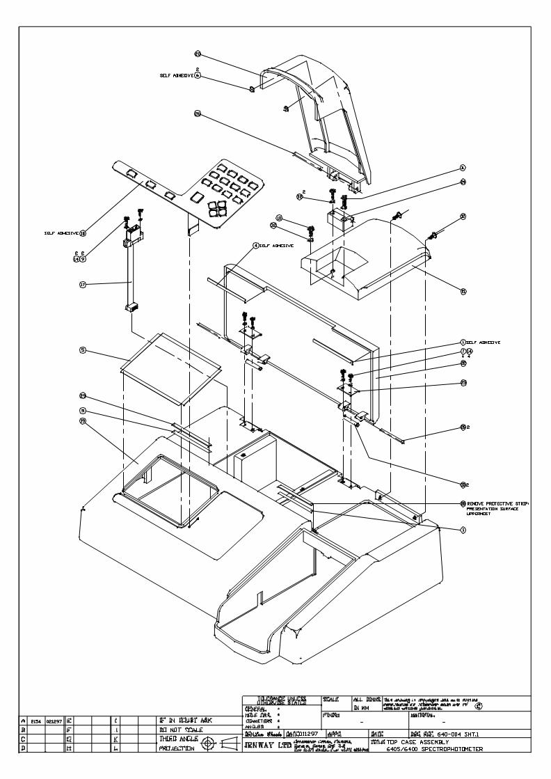
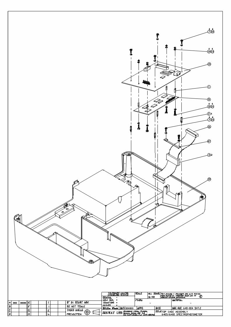
Microprocessor/Display PCB The microprocessor/display PCB ismounted in the top case assembly. To remove it disconnect PL3 tothe internal printer, PL2 to the power supply PCB, and PL4 to themembrane keypad. Unscrew the four outer screws and the twoboards can be removed. The display module can be separated fromthe microprocessor PCB by unplugging PL6 and unscrewing theother four screws that pass through the pillars and are fixed withnuts and washers. When reassembling ensure that the membranekeypad strip connector passes through the slot in the PCB.
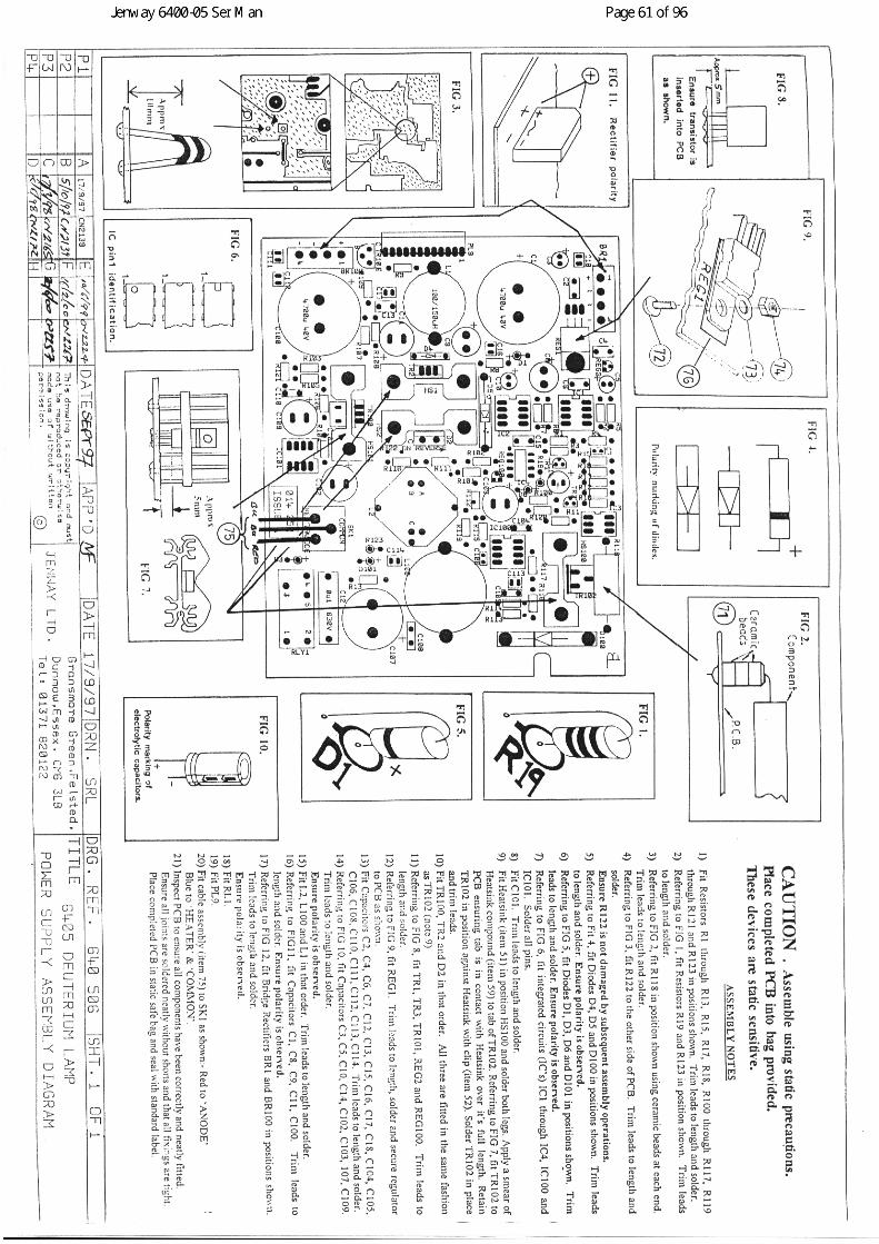
Deuterium Lamp Supply PCB The Deuterium Lamp Supply PCBis mounted in the lower case assembly and plugs (at 90 degrees)into the Power Supply PCB. To remove it unscrew the two screwsthat hold the right hand bracket into the base. Lift the bracket clearof the two earth wires and put to one side with the screws.Carefully unplug the Deuterium Lamp Supply PCB from the PowerSupply PCB. To completely remove it from the instrument, unplugthe Deuterium lamp and pull the connector through the mouldedchannel. When replacing make sure the pins on the connector to thePower Supply PCB are correctly aligned and that the PCB iscorrectly located in the grove in the case.
Power Supply
Disconnect the large multi-pin connector to the transformer, PL6,then the four smaller connectors on the lower front side of thePCB, PL1, PL3, PL12 and PL5, then remove PL7 from the top ofthe PCB. Remove the two screws from the lower case moulding
Jenway 6400-05 Ser Man Page 43 of 96
that secure the bracket at the front edge of the PCB, remove thebracket and screws and place to one side. Remove the two screwsthat hold the bracket to the rear panel and lift out the PCB.
When replacing the PCB ensure that it fits correctly into the groovein the chassis moulding and if re-connecting the Deuterium LampSupply PCB ensure that the pins on the right angle connectors arecorrectly aligned.
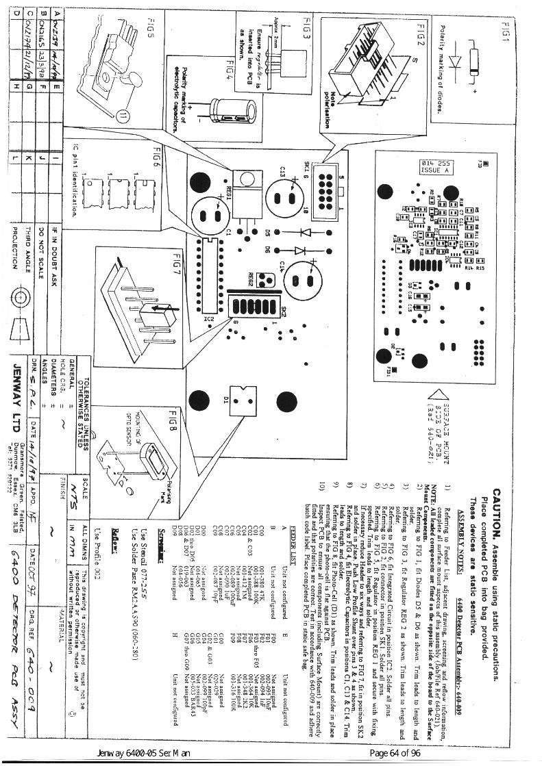
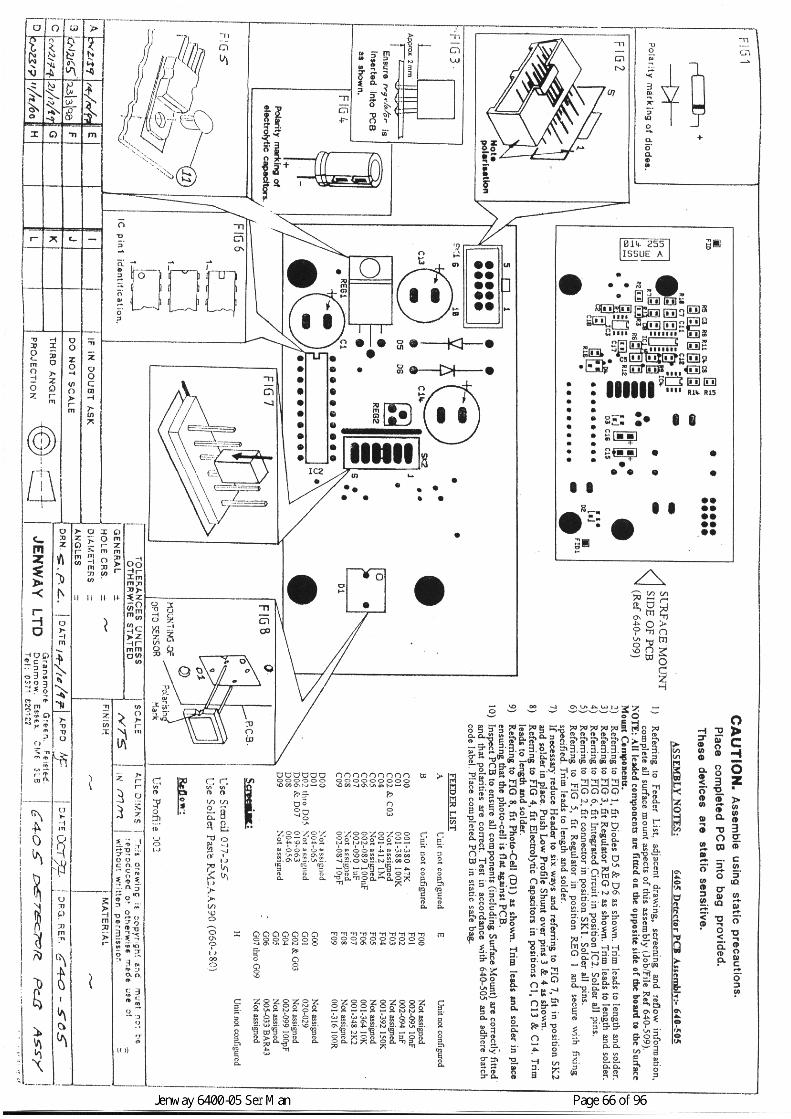
Detector PCB The detector PCB is mounted vertically at the farright hand side of the lower chassis. It is easily removed byunscrewing the two screws recessed in the top of the metalmounting block, the plugs in SK1 and SK2 should also beremoved. Remove the two screws and spacers that hold the lensblock, take care not to rotate it as the detector is mounted in arecess inside the block and can easily be broken off. Remove thelast screw with its nut and washer to enable the electrostatic screento be removed from the PCB.
The Detector PCB stores detailed calibration data relating to theoptics of the unit it is fitted in, replacing the detector PCB withouta full re-calibration will invalidate the quoted specification.
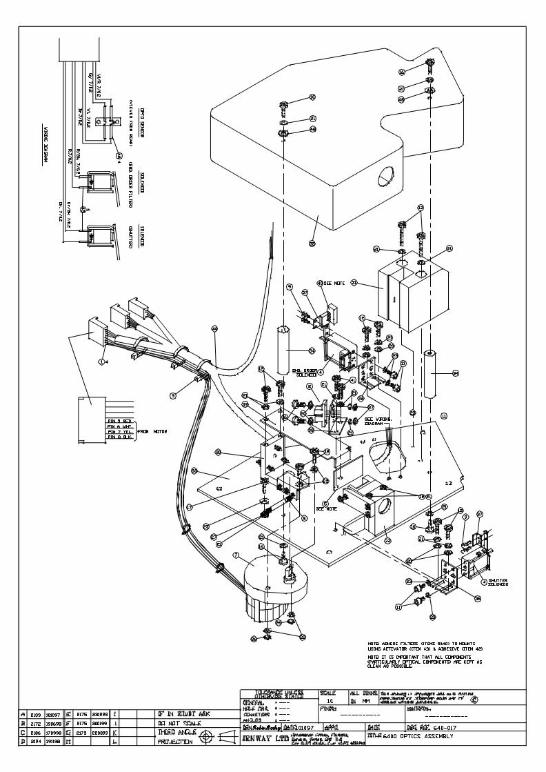
Monochromator The monochromator is located in the centre ofthe lower case. It is a sealed unit and breaking the seals willinvalidate the warranty. Before proceeding with replacementensure the unit is in a clean, dust and humidity free area.
First remove the top cover by unscrewing the two screws in thetop, remove the top cover and place to one side. Do not touch anyoptical components. Then remove the four screws from the baseplate, two at the front, two at the rear. Lift the monochromatorassembly by the pillars only, unplug the connectors PL5, PL1, andPL3. Remove the Yellow/Black and Yellow wires from PL1 to freethe monochromator from the lamp assembly.
Replacement is the reverse of dismantling, but ensure a fullcalibration is run so that the new calibration data is stored on theDetector PCB.
Jenway 6400-05 Ser Man Page 44 of 96
Sampling Accessory/Driver PCB The sampling accessory and itsdriver PCB can be accessed without removing the top half of thecase. The mechanical part of the accessory can often be fitted bysimply opening the sample cover, however for more complexarrangements or where a replacement driver PCB has to be fittedaccess can be gained by removing the complete sample chambercover. To do this turn the instrument around and remove the twocountersunk screws in the back of the grey moulding that is thefixed part of the sample chamber cover. Lift the sample chamberlid and remove the single screw at the front of the same moulding,do not touch the two screws in the black hinge block. This willenable the complete sample chamber cover to be removed.
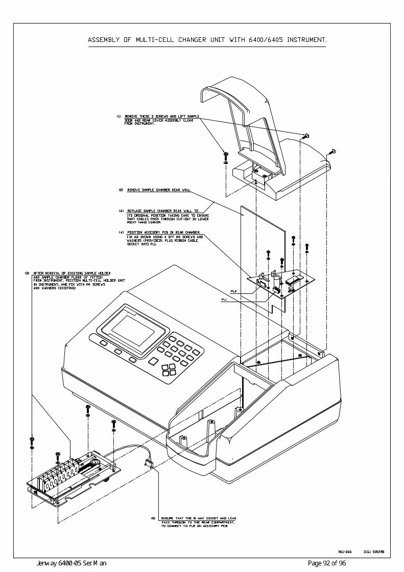
Multi-Cell Changer Assembly This accessory is required for theQuantitation mode of operation to become active. It is easily fittedin the following manner: - (See Section 10.9 Assembly Diagrams)
Remove the complete sample chamber cover assembly as detailedabove. Then remove the cuvette holder assembly by loosening thelarge thumb-screw at the front of the sample chamber. The cuvetteholder fixing plate should then be removed by unscrewing the foursmall countersunk screws. Finally the sample chamber base plateshould be removed by unscrewing the four pan head screws thathold it in place. Slide the sample chamber back plate up and out ofits retaining groove. Note the cut out in its lower right corner.
Place the multi-cell changer assembly in the sample compartmentso that the four cut outs pass over the four moulded pillars in thecase. Ensure that the cable and connector pass freely from the rearof the assembly before screwing into place with the four pan headscrews, two at the front, two at the rear. It is acceptable to slide thecuvette rack forward to uncover the rear fixing holes if required,the position will be correctly re-set on power up.
Fit the Accessory PCB in the rear chamber with the four screwssupplied and plug the motor connector into PL2 and the 10 pin IDCconnector into PL1. This PCB holds the calibration data for themulti-cell changer positioning stepper motor so the mechanicalassembly and this PCB must be treated as a matched pair.
Replace the sample chamber rear wall in its retaining groove andensure that the cable passes under the cut out in the lower rightcorner and is not trapped or damaged by the plate.
Jenway 6400-05 Ser Man Page 45 of 96
Replace the sample chamber lid assembly and check that it opensand closes correctly. Verify the instrument performance asnecessary
8.3 Energy Levels
Equipment Required; - None, checked against internal settings.
Before proceeding with any calibration it is essential to ensure thecorrect functioning of the optical system, this can be done veryeasily in the Diagnostics Menu (see Section 7) where the followingperformance should be obtained.
6405 onlyU V Energy, Set wavelength to 190nm, Dark Shutter open, IRstray light filter closed, UV, second order stray light filter open;Voltage Display must be greater than 20mV.
Visible Energy, Set wavelength to 805nm, Dark Shutter open, IRstray light filter open, UV second order stray light filter closed;Voltage Display must be greater than 1000mV and less than3600mV.
Dark Current, Set wavelength to 320nm, Dark Shutter closed, IRstray light filter closed, UV second order stray light filter open;Voltage Display should be zero +/- 6mV.
320nm Output, Set wavelength to 320nm, UV lamp off, DarkShutter open, IR stray light filter closed, UV second order straylight filter open; Voltage Display must be greater than 17mV.
8.4 Wavelength Calibration
Equipment Required; - A certified wavelength standard, i.e.Holmium Oxide Filter, Holmium Perchlorate Solution etc. (SeeSection 8.7.1)
Wavelength calibration can be carried out in the Diagnostics Modeusing the wavelength (zero order) offset function. Do not carry out

Jenway 6400-05 Ser Man Page 46 of 96
the following procedure without a suitable, certified wavelengthcalibration standard.
Turn the unit on and allow the Start Up tests to complete.
Select the Spectrum Mode from the Main Menu.
Set up a scan of the certified wavelength calibration standard using aresolution of 0.2nm over the minimum wavelength range needed toisolate the peak of interest. Carry out a Baseline scan using these settings,and then scan the wavelength calibration standard.
Use the Peak and Valley table or the cursor to identify and record thewavelength of the peak of interest.
Repeat the above and check that the same value is reported.
Calculate the adjustment required to correctly align the reported figurewith the certified value.
Certified Value – Reported Value = Correction factor (can be negative orpositive, maximum correction permissible is 3.0nm)
Switch the unit off and re-start it in the Diagnostics Mode by holdingdown the right hand arrow key <>> while turning power on.
Make a note of the value in the Wavelength (zero order) Offset option,including whether negative or positive.
Press the number six <6> key to clear the Wavelength (zero order) Offsetentry.
Enter a new number calculated from; (Correction Factor x 10) + existingvalue. If this is negative press the sign (+/-) key first to bring up thenegative sign. Then press enter to confirm the value.
Switch the unit off and then on again, allowing the Start Up tests to becompleted, re-scan the certified wavelength calibration standard andcheck that the reported value is now correct.
Jenway 6400-05 Ser Man Page 47 of 96
8.5 A to D Calibration
The A to D converter should only be calibrated by engineers whohave been trained on this aspect of servicing by Jenway Limited.
Equipment Required; - A certified voltage calibrator with aresolution of 0.1mV and a range up to at least +/-4.0000V.A lead for connecting the calibrator to pins 1 (negative) and pin 3(positive) of SK2 on the detector PCB. (8 pin Molex typeconnector)
Access the Detector PCB by removing the top case assembly asdescribed in Section 8.2 - Dismantling.
Remove the plug from SK2 on the Detector PCB and replace withthe one connected to the calibrator.
Switch the calibrator on and select a negative output (or reverse thecontacts)
Select the Diagnostics menu by turning the unit on with the righthand <>> arrow key depressed.
Press the Print Key to activate the Calibrate ADC menu option.
The menu line will change to prompt for specific input levels andshow the relevant channel output counts.
First is –1mV, set the calibrator to give an input signal of –1mVand then press the enter key.
Then the prompt changes to –20mV, set the calibrator to –20mVand then press the enter key.
Continue responding to the prompts in this way for –39mV,-200mV, -390mV, -2000mV and –3900mV. Note that the –39mVand –390mV levels are repeated as these are the cross over pointsfrom one channel to the next.
When all the levels have been correctly entered and stored themenu option returns to its original state.

Jenway 6400-05 Ser Man Page 48 of 96
8.6 D to A Calibration
Equipment required; - Voltmeter capable of reading 2.0V with aresolution of 1mV.
The D to A calibration sets the levels of the analogue output. Thisis carried out with the on-board voltage reference at zero and +/-2000mV.
Select the Diagnostics menu by turning the unit on with the righthand <>> arrow key depressed.
Press the Seven <7> Key to activate the Calibrate DAC menuoption.
The menu line will change to prompt for specific input levels andshow the relevant channel output counts.
Connect a voltmeter to the analogue output on the rear panel.Select a range that will display 2000mv to 0.1mV resolution.
The first prompt indicates an output level of -2000mV, use the upand down and left and right arrow keys to adjust the actual readingon the voltmeter to –2000mV.
The left and right arrow keys change the output in 5mV steps, theup and down arrow keys in 0.5mV steps.
When the correct level is reached press the enter key and theprompt moves on to 0mV, repeat the above for this and the2000mV levels.
When successfully completed the Calibrate DAC menu optionreturns to its original state.
Jenway 6400-05 Ser Man Page 49 of 96
8.7 Performance Verification
Equipment Required; - 1. Certified Wavelength Standard,2. Certified Absorbance Standards, 3. Certified Stray LightStandard.
Items 1 and 2 above can be supplied as Calibration Filter Sets, order partnumbers 035 088 for the 6400 or 035 091 for the 6405.
Where filters are not available the following reagents may be used:
8.7.1 Holmium Perchlorate – 5% w/v solution of Holmium Oxide in1.4N Perchloric acid, this will give absorbance maxima at 241.0,278.1, 287.0, 361.4, 416.1, 451.1, 485.3, 536.5 and 640.5.
8.7.2 Potassium Dichromate – 100.0mg/l in 0.005M Sulphuric Acid (usethe Sulphuric Acid as the blank). This will give Absorbance valuesof 1.071 at 350nm, 0.484 at 313nm, 1.444 at 257nm, 1.242 at 235.Potassium Dichromate – 50.0mg/l in 0.005M Sulphuric Acid (usethe Sulphuric Acid as the blank). This will give Absorbance valuesof 0.536 at 350nm, 0.242 at 313nm, 0.722 at 257nm, 0.621 at 235.
8.7.3 Sodium Nitrate – 50g/l in deionised water, should give less than0.1% transmittance at 340nm.Sodium Iodide – 10g/l in deionised water, should give less than0.1% transmittance at 220nm.
All these solutions are hazardous and the manufacturer/supplierssafety precautions should be carefully followed at all times inpreparation, use and storage.
8.7.4 Wavelength Verification
Equipment Required; - A certified wavelength standard, i.e. HolmiumOxide Filter, Holmium Perchlorate Solution etc. (See Section 8.7.1)
Turn the unit on and allow the Start Up tests to complete then allow 15minutes for the instrument to warm up.
Select the Spectrum Mode from the Main Menu.
Jenway 6400-05 Ser Man Page 50 of 96
Set up a scan of the certified wavelength calibration standard or HolmiumPerchlorate solution using a resolution of 0.2nm over the minimumwavelength range needed to isolate the peaks of interest. Adjust the NoiseFilter or Smoothing and the resolution to give clean peaks without anyinterfering spikes.
Carry out a Baseline scan using these settings, and then scan thewavelength calibration standard or Holmium Perchlorate solution.
Use the table of peaks or the cursor to check that the wavelengths of thepeaks of interest fall within the specified tolerance of the instrumentPLUS the tolerance of the filter/reagent used.
8.7.5 Absorbance Verification
Equipment Required; - Certified Standard Absorbance Filters orPotassium Dichromate solution. (See Section 8.7.2)
Turn the unit on and allow the Start Up tests to complete then allow 15minutes for the instrument to warm up.
Select the Photometrics Mode from the Main Menu.
Select a wavelength at which the filter or solution is certified.
For the Potassium Dichromate solution use the Sulphuric Acid solution asa blank, (See Section 8.7.2) if the filter set includes a zero filter use thisas the blank, if not set the blank (zero absorbance or 100% transmittance)with an empty sample chamber.
Insert the certified filter or Potassium Dichromate solution and check thatthe reading is within the specified tolerance of the instrument PLUS thetolerance of the filter/solution used.
Repeat this for other filters or solutions and at other specifiedwavelengths as necessary.
Jenway 6400-05 Ser Man Page 51 of 96
8.7.6 Stray Light Verification
Equipment Required; - Certified Stray Light Filters or Sodium NitrateSolution or Sodium Iodide Solution. (See Section 8.7.3)
Turn the unit on and allow the Start Up tests to complete then allow 15minutes for the instrument to warm up.
Select the Photometrics Mode from the Main Menu.
Select a wavelength at which the filter or solution is certified (340nm forSodium Nitrate or 220nm for Sodium Iodide).
Set 100% transmittance with a quartz cuvette filled with the deionisedwater used to make up the solutions or with the blank filter supplied bythe manufacturer.
Insert the stray light filter or solutions, as above, and ensure that thereading is within the specified tolerance of the instrument PLUS thetolerance of the filter/solution used.
Jenway 6400-05 Ser Man Page 52 of 96
Section 9
Circuit Diagrams
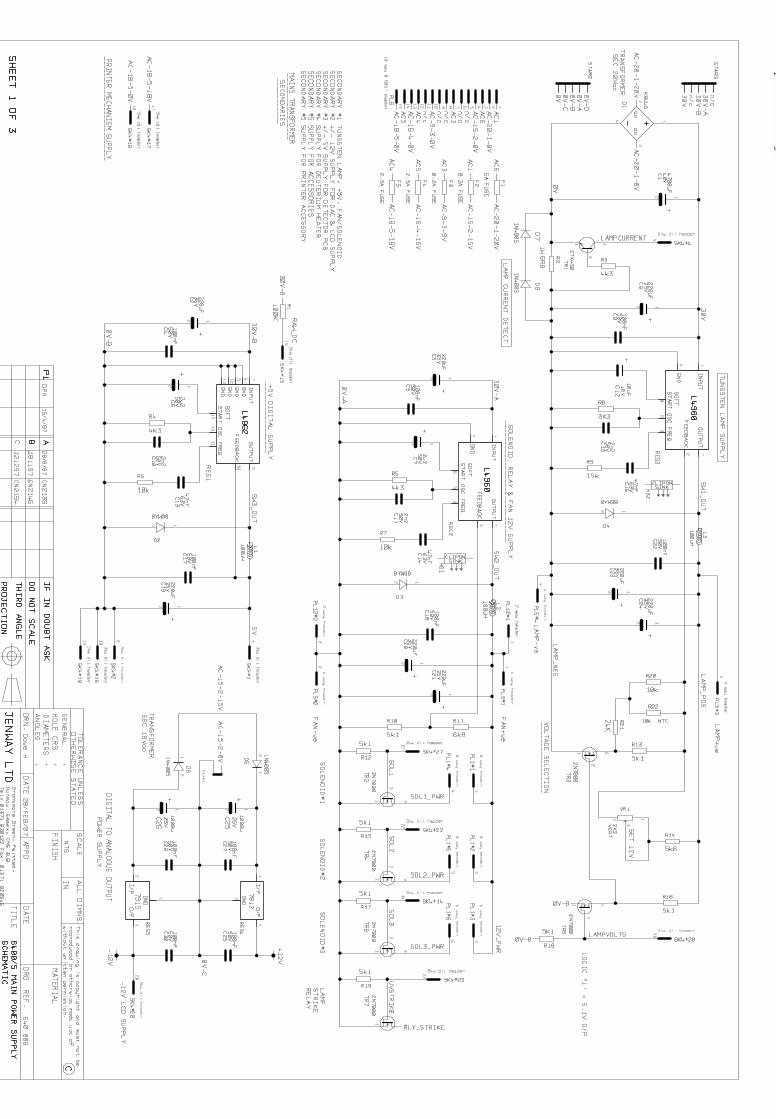
9.10 Power Supply Schematic 640 008 (3pgs)9.11 Power Supply Layout 640 008 (1pg)
9.20 Deuterium Lamp Supply Schematic 640 506 (2pgs)9.21 Deuterium Lamp Supply Layout 640 506 (1pg)
9.30 Detector PCB Schematic 640 009 (1pg)9.31 Detector PCB Layout 640 009 (1pg)9.32 Detector PCB Schematic 640 505 (1pg)9.33 Detector PCB Layout 640 505 (1pg)
9.40 Microprocessor PCB Schematic 640 007 (2pgs)9.41 Microprocessor PCB Layout 640 007 (1pg)
9.50 Accessory Driver PCB Schematic 642 003 (1pg)9.51 Accessory driver PCB Layout 642 003 (1pg)
Jenway 6400-05 Ser Man Page 53 of 96
Section 9
Circuit Diagrams
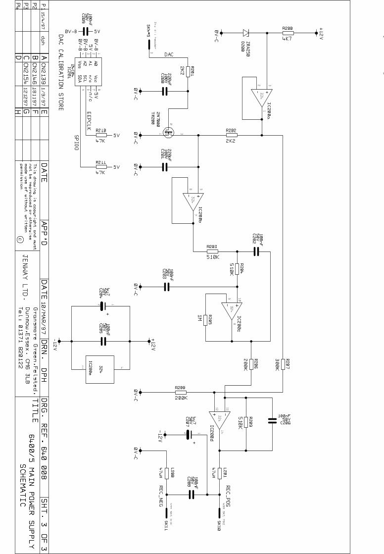
9.10 Power Supply Schematic - 640 008 – 3 pages
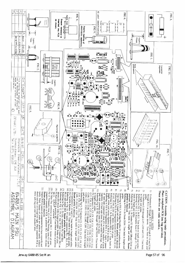
9.11 Power Supply Layout – 640 008 – 1 page
powerc1.dgm
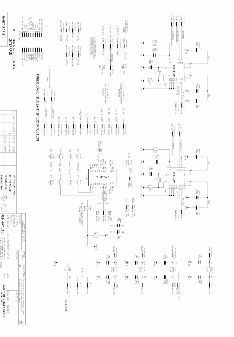
powerc2.dgm
powerc3.dgm
Section 9
Circuit Diagrams
9.20 Deuterium Lamp Supply Schematic – 640 506– 2 pages
9.21 Deuterium Lamp Supply Layout - 640 506– 1 page
U:\DATA\USR\ENGMASTER\PCB and Circuit Diagrams\014252\Issue A\640506a1.dgm
U:\DATA\USR\ENGMASTER\PCB and Circuit Diagrams\014252\Issue A\640506a2.dgm
9.32 Detector PCB Schematic – 640 505 – 1 page
9.33 Detector PCB Layout – 640 505 – 1 page
Jenway 6400-05 Ser Man Page 67 of 96
Section 9
Circuit Diagrams
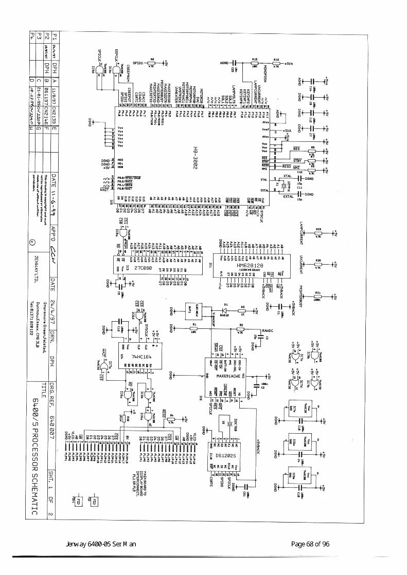
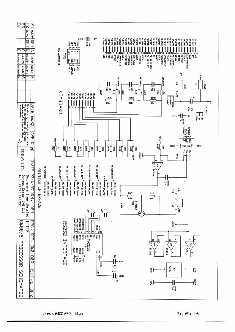
9.40 Microprocessor PCB Schematic – 640 007– 2 pages
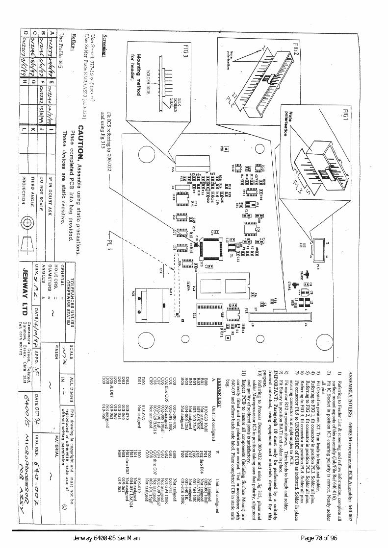
9.41 Microprocessor PCB Layout - 640 007- 1 page
Jenway 6400-05 Ser Man Page 71 of 96
Section 9
Circuit Diagrams
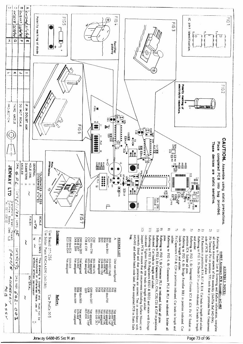
9.50 Accessory Driver PCB Schematic – 642 003 –1 page
9.51 Accessory Driver PCB Layout – 642 003 –1 page
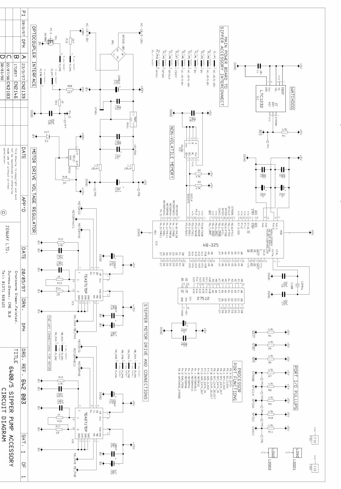
U:\DATA\USR\ENGMASTER\PCB and Circuit Diagrams\014256\Issue C\014-256c.dgm
Jenway 6400-05 Ser Man Page 74 of 96
Section 10
Assembly Diagrams
10.1 6400 Final Assembly 640 003
10.2 6405 Final Assembly 640 503
10.3 6400 Lower Case Assembly 640 005 (2 pgs)
10.4 6405 Lower Case Assembly 640 504 (2 pgs)
10.5 6400/05 Top Case Assembly 640 004
10.6 6400 Optics Assembly 640 017
10.7 6405 Optics Assembly 640 510
10.8 6400/05 Rear Panel Assembly 640 006
10.9 6400/05 Multi-Cell Changer 644 002

Jenway 6400-05 Ser Man Page 75 of 96
Section 10
Assembly Diagrams
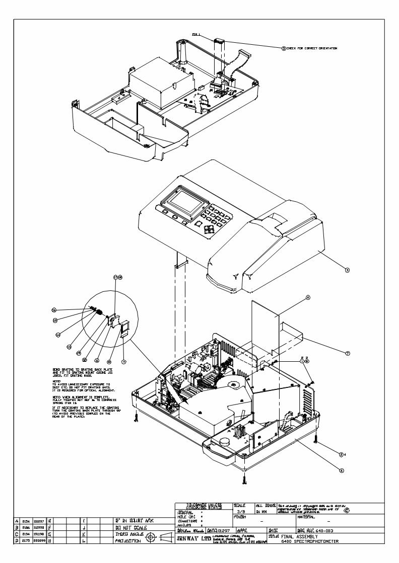
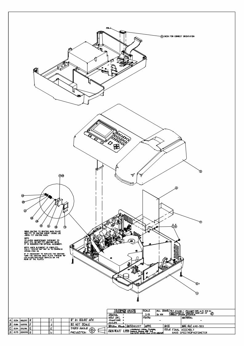
10.1 6400 Final Assembly – 640 003
10.2 6405 Final Assembly – 640 503
Jenway 6400-05 Ser Man Page 78 of 96
Section 10
Assembly Diagrams
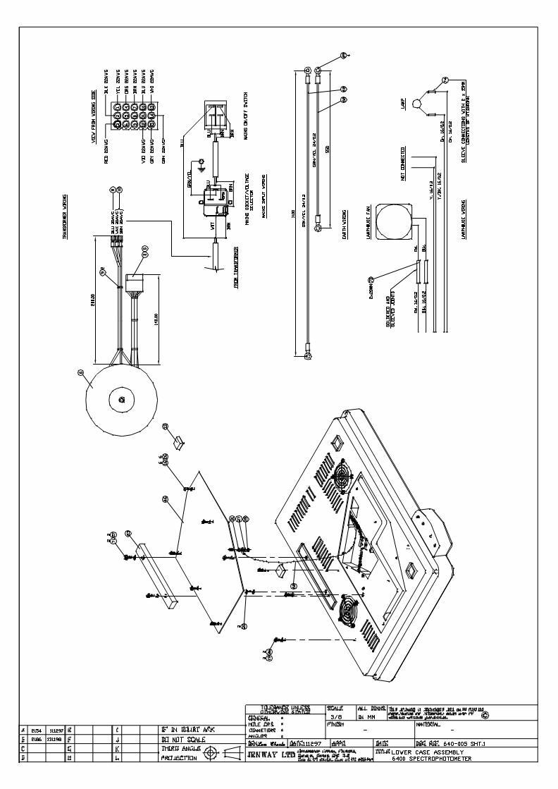
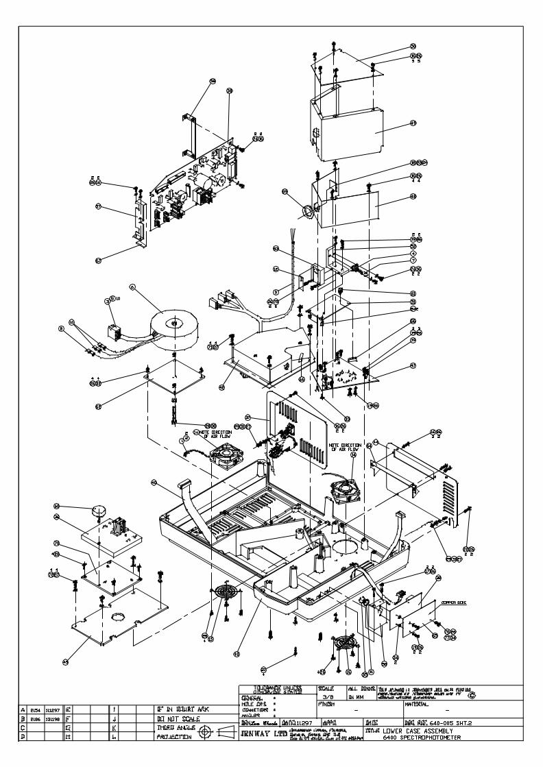
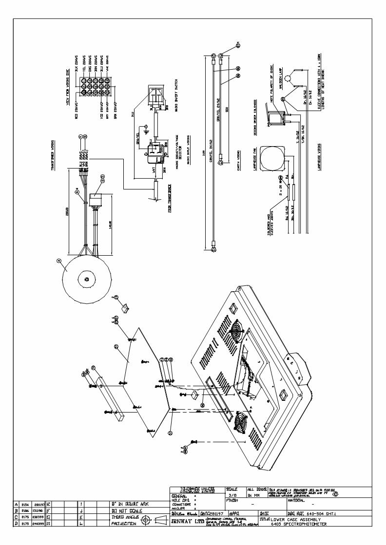
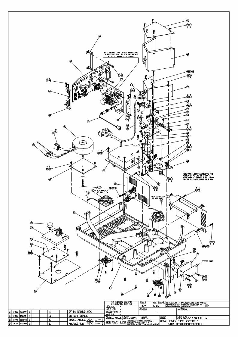
10.3 6400 Lower Case Assembly – 640 005
10.4 6405 Lower Case Assembly – 640 504
Jenway 6400-05 Ser Man Page 83 of 96
Section 10
Assembly Diagrams
10.5 6400/05 Top Case Assembly – 640 004
Jenway 6400-05 Ser Man Page 86 of 96
Section 10
Assembly Diagrams
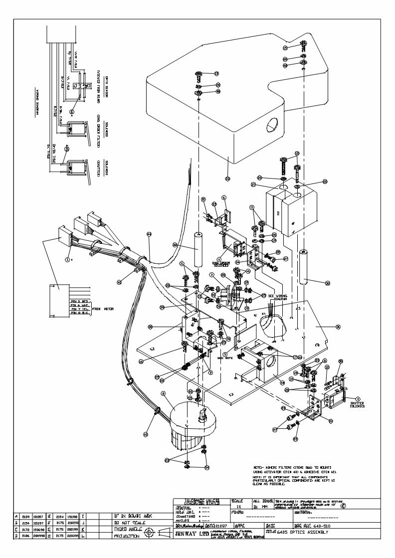
10.6 6400 Optics Assembly – 640 017
10.7 6405 Optics Assembly – 640 510
Jenway 6400-05 Ser Man Page 89 of 96
Section 10
Assembly Diagrams
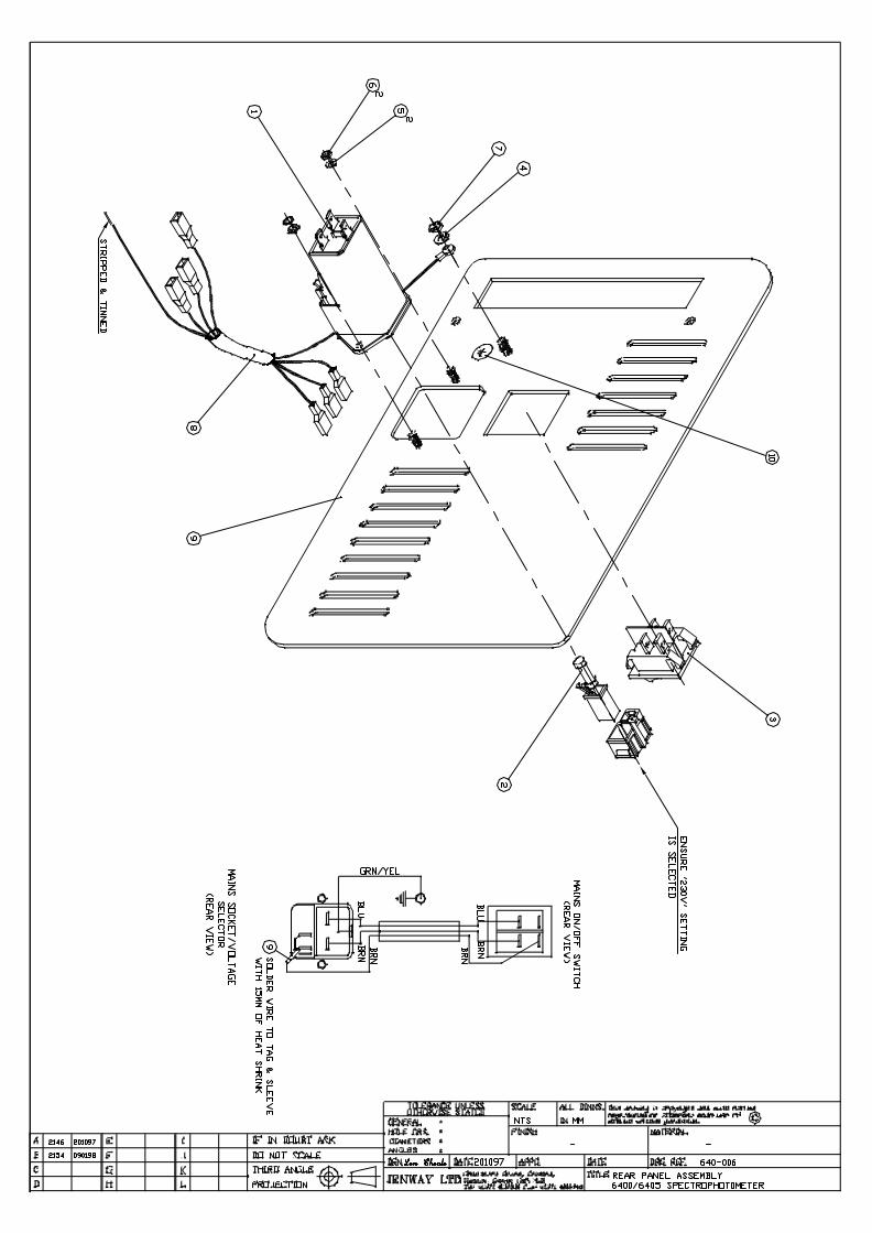
10.8 6400/05 Rear Panel Assembly – 640 006
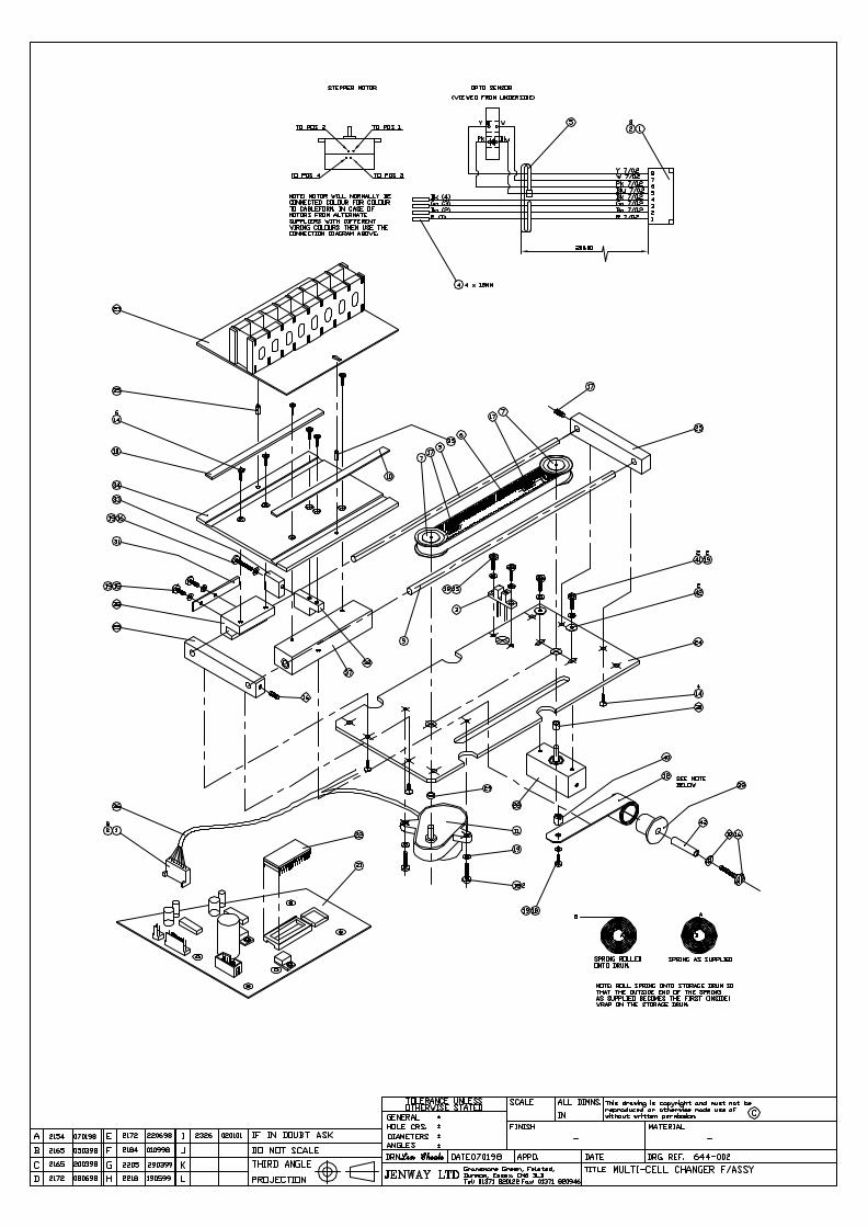
10.9 6400/05 Multi-Cell Changer – 644 002
Jenway 6400-05 Ser Man Page 93 of 96
Section 11
Spare Parts
11.01 Packed Instrument
11.02 Top Case Assembly
11.03 Microprocessor PCB
11.04 Lower Case Assembly
11.05 Lamp Housing Assembly
11.06 Optics Assembly
11.07 Detector PCB
11.08 Power Supply PCB
11.09 Deuterium Lamp Supply PCB
11.10 Rear Panel Assembly
11.11 Multi-Cell Changer PCB
11.12 Built-In Printer Option
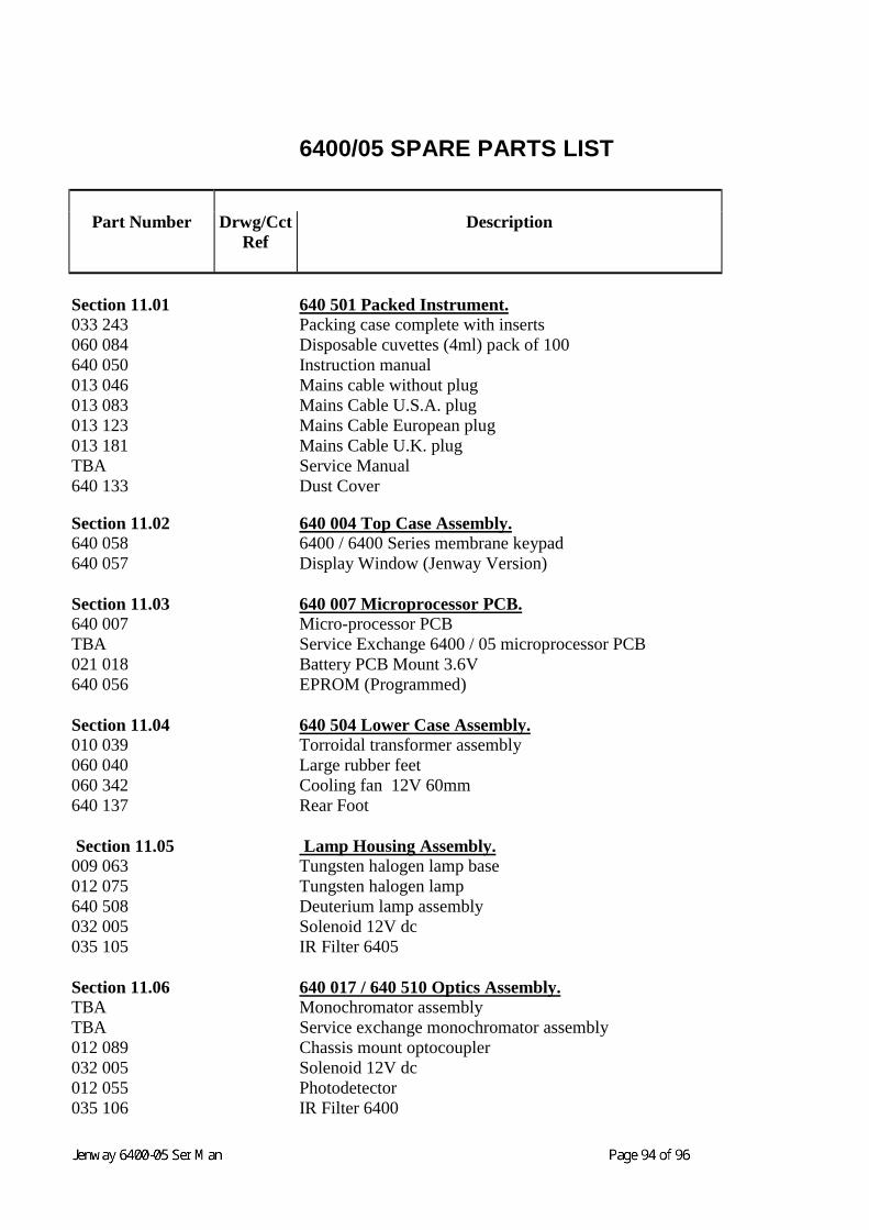
6400/05 SPARE PARTS LIST
Part Number Drwg/CctRef
Description
Section 11.01 640 501 Packed Instrument.033 243 Packing case complete with inserts060 084 Disposable cuvettes (4ml) pack of 100640 050 Instruction manual013 046 Mains cable without plug013 083 Mains Cable U.S.A. plug013 123 Mains Cable European plug013 181 Mains Cable U.K. plugTBA Service Manual640 133 Dust Cover
Section 11.02 640 004 Top Case Assembly.640 058 6400 / 6400 Series membrane keypad640 057 Display Window (Jenway Version)
Section 11.03 640 007 Microprocessor PCB.640 007 Micro-processor PCBTBA Service Exchange 6400 / 05 microprocessor PCB021 018640 056
Battery PCB Mount 3.6VEPROM (Programmed)
Section 11.04 640 504 Lower Case Assembly.010 039 Torroidal transformer assembly060 040 Large rubber feet060 342 Cooling fan 12V 60mm640 137 Rear Foot
Section 11.05 Lamp Housing Assembly.009 063 Tungsten halogen lamp base012 075 Tungsten halogen lamp640 508 Deuterium lamp assembly032 005 Solenoid 12V dc035 105 IR Filter 6405
Section 11.06 640 017 / 640 510 Optics Assembly.TBA Monochromator assemblyTBA Service exchange monochromator assembly012 089 Chassis mount optocoupler032 005 Solenoid 12V dc012 055 Photodetector035 106 IR Filter 6400
Jenway 6400-05 Ser Man Page 95 of 96
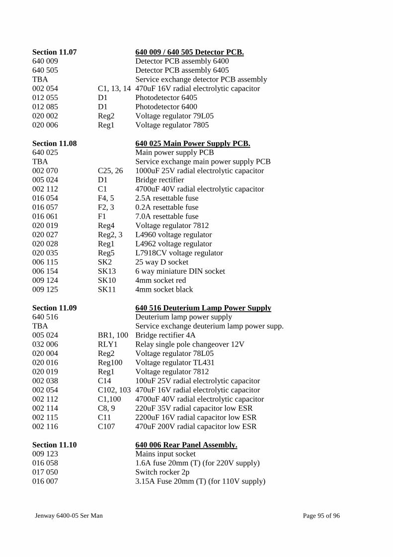
Section 11.07 640 009 / 640 505 Detector PCB.640 009640 505
Detector PCB assembly 6400Detector PCB assembly 6405
TBA Service exchange detector PCB assembly002 054 C1, 13, 14 470uF 16V radial electrolytic capacitor012 055012 085
D1D1
Photodetector 6405Photodetector 6400
020 002 Reg2 Voltage regulator 79L05020 006 Reg1 Voltage regulator 7805
Section 11.08 640 025 Main Power Supply PCB.640 025 Main power supply PCBTBA Service exchange main power supply PCB002 070 C25, 26 1000uF 25V radial electrolytic capacitor005 024 D1 Bridge rectifier002 112 C1 4700uF 40V radial electrolytic capacitor016 054 F4, 5 2.5A resettable fuse016 057 F2, 3 0.2A resettable fuse016 061 F1 7.0A resettable fuse020 019 Reg4 Voltage regulator 7812020 027 Reg2, 3 L4960 voltage regulator020 028 Reg1 L4962 voltage regulator020 035 Reg5 L7918CV voltage regulator006 115 SK2 25 way D socket006 154 SK13 6 way miniature DIN socket009 124 SK10 4mm socket red009 125 SK11 4mm socket black
Section 11.09 640 516 Deuterium Lamp Power Supply640 516 Deuterium lamp power supplyTBA Service exchange deuterium lamp power supp.005 024 BR1, 100 Bridge rectifier 4A032 006 RLY1 Relay single pole changeover 12V020 004 Reg2 Voltage regulator 78L05020 016 Reg100 Voltage regulator TL431020 019 Reg1 Voltage regulator 7812002 038 C14 100uF 25V radial electrolytic capacitor002 054 C102, 103 470uF 16V radial electrolytic capacitor002 112 C1,100 4700uF 40V radial electrolytic capacitor002 114 C8, 9 220uF 35V radial capacitor low ESR002 115 C11 2200uF 16V radial capacitor low ESR002 116 C107 470uF 200V radial capacitor low ESR
Section 11.10 640 006 Rear Panel Assembly.009 123 Mains input socket016 058 1.6A fuse 20mm (T) (for 220V supply)017 050 Switch rocker 2p016 007 3.15A Fuse 20mm (T) (for 110V supply)
Jenway 6400-05 Ser Man Page 96 of 96
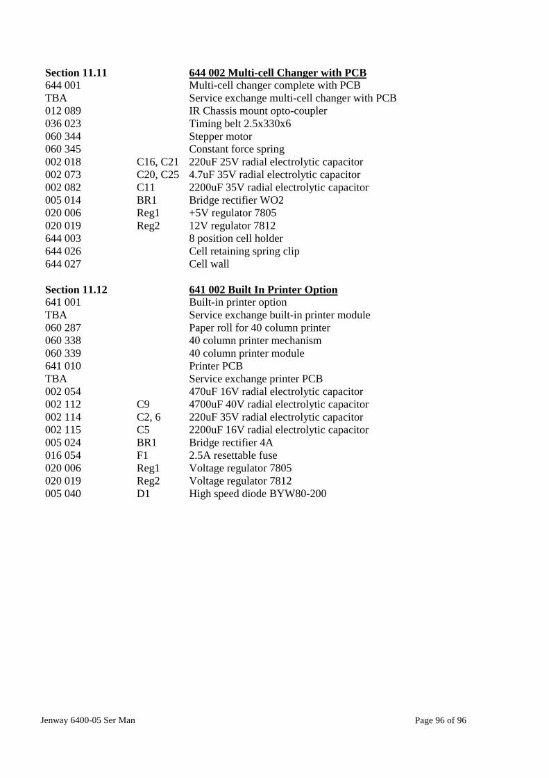
Section 11.11 644 002 Multi-cell Changer with PCB644 001 Multi-cell changer complete with PCBTBA Service exchange multi-cell changer with PCB012 089 IR Chassis mount opto-coupler036 023 Timing belt 2.5x330x6060 344 Stepper motor060 345 Constant force spring002 018 C16, C21 220uF 25V radial electrolytic capacitor002 073 C20, C25 4.7uF 35V radial electrolytic capacitor002 082 C11 2200uF 35V radial electrolytic capacitor005 014 BR1 Bridge rectifier WO2020 006 Reg1 +5V regulator 7805020 019 Reg2 12V regulator 7812644 003 8 position cell holder644 026 Cell retaining spring clip644 027 Cell wall
Section 11.12 641 002 Built In Printer Option641 001 Built-in printer optionTBA Service exchange built-in printer module060 287 Paper roll for 40 column printer060 338 40 column printer mechanism060 339 40 column printer module641 010 Printer PCBTBA Service exchange printer PCB002 054 470uF 16V radial electrolytic capacitor002 112 C9 4700uF 40V radial electrolytic capacitor002 114 C2, 6 220uF 35V radial electrolytic capacitor002 115 C5 2200uF 16V radial electrolytic capacitor005 024 BR1 Bridge rectifier 4A016 054 F1 2.5A resettable fuse020 006 Reg1 Voltage regulator 7805020 019 Reg2 Voltage regulator 7812005 040 D1 High speed diode BYW80-200