Embed Size (px)
Citation preview

UsingJerguson®/Jacoby-Tarbox®Eductors forPumping Liquids
-
Section: E200Bulletin: E200.1Version: 1/93Supersedes: New
IJRG/JT~ Models for Pumping Liquids
Principles of Operationfor Pumping LIquids
Operating Specifications·
Model Sl Ml Hl SG HG
Motive Media liquid liquid liquid Steam Steam
Motive Pressure (PSIG) 15-250 15·250 15·250 30-150 20-150
Pressure Recovery % 10-15 30-35 40-50 15-20 30-35
Maximum Suction lift -27 Ft -27 Ft -27 Ft -20 Ft -20 Ft
Minimum Required NPSH 3ft 3Ft 3ft 13 Ft 13 Ft
·Pumping water, 68°F
Typical Applications
Motive Fluid
liquid
Pump from TankPump from sump
Dilute in lineTransport liquid
Sl, ML. Hl
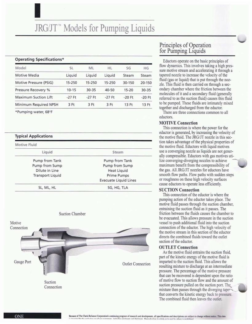
Suclion Chamber
MotiveConnection
......1
,Gauge Pon
SuctionConneclion
Steam
Pump from TankPump from Sump
Heat liquidPrime Pumps
Evacuate liquid lines
SG, HG, TLA
......
Outlet Connection
Eductors operate on Ihe basic principles offlow dynamics. This involves taking a high pressure motive stream and accelerating it through atapered nozzle to increase the velocity of thefluid (gas or liquid) that is put through the noz·zle. This fluid is then carried on through a secondary chamber where the friction between themolecules of it and a secondary fluid (generallyreferred to as the suction fluid) causes this fluidto be pumped. These fluids are intimately mixedtogether and discharged from the eductor.
There are three connections common to alleduclOrs.MOTIVE Connection
This connection is where the power for theeduclOr is generated, by increasing the velocity ofthe motive fluid. The JRG/JT nozzle in this section takes advantage of the physical properties ofthe motive fluid. Eductors with liquid motivesuse a converging nozzle as liquids are not generally compressible. Eductors with gas motives uti·Iize converging-diverging nozzles to achievemaximum benefit from the compressibility ofthe gas. All JRG/lT nozzles for eductors havesmooth flow paths. Flow paths with sudden stepsor roughness on these high velocity surfacescause eductors to operate less efficiently.SUCTION Connection
This connection of the eductor is where thepumping action of the eductor takes place. Themotive fluid passes through the suction chamber,entraining the suction fluid as it passes. Thefriction between the fluids causes the chamber tobe evacuated. This allows pressure in the suctionvessel to push additional fluid into the suctionconnection of the eductor. The high \'e\ocity ofthe motive stream in this section of the educlordirects the combined fluids toward the outletsection ofthe eductor.OUTLET Connection
As the motive fluid entrains the suction fluid,part of the kinetic energy oflhe motive fluid isimparted to the suction fluid. This allows theresulting mixture to discharge at an intermediatepressure. The percentage of the motive pressurethat can be recovered is dependent upon the ratioof motive flow to suction flow and the amount ofsuction pressure pulled on the suction port. Th;.mixture then passes through the diverging tape'l"'_thai com'erts the kinetic energy back to pressure..The combined fluid then leaves the outlet
0\1 _dn..Clott·Rdioooa:~\ d.......tl ~ _ n.._.._~ ... _ ............ _..i ~_._ .... *""- ._.........._'-_ _~__

IHow to Size Liquid Motive Eductors for Pumping Liquids
Using Liquid Motives toPump Liquid Suction Fluids
To determine the correct eductor for a spe·cifie application, follow the steps in this sec·tion, using the performance tables (pages3-4) provided to achieve your desired results.(NOTE: All JRG/JT tables use the 1-1/2 inchunit as the standard, and educlors are sizedusing a Sizing Factor (S.F.) based on thisstandard uni!.)
Step 1 Find the suction lift* or head (Hs)that is equal 10 or greater than your desiredlift.lrYOUT lift is between (wO of the liftson the table, use an average of the two. Youcan also or use the calculated result from theNPSH formula found on page 5 of thismanuaL Using the NPSH number will correct for temperature variations and frictionlosses, resulting in a more accurate value.
Step 2 Find the outlet head·· (Ho) equalto or greater than your actual outlet head. It
"--iiis important to include friction losses intot e desired outlet head. (Be certain that friction losses in the outlet line are calculatedusing the combined rate ofborh the motiveand the suction flows.) II is important thatthe outlet line from the eductor be as largeor larger than the outlet connection.
Step 3 Find the motive pressure (pm)."Locate the motive pressure from the tablethat is closest to or fOlrer than your actualmotive pressure. The flow specified represents the Tabulated Suction Flow for each ofthe different models ofeductors. To determine the size ofeductor needed first usethe following formula to determine theDesired Sizing Factor (S.F.) Do this for eachof the models.D . d S F Desired Suction Flow
eSlre .. Tabulated Suction Flow
Ifa standard unit is being used, pick thesize unit that has a Tabulated S.F. (page 7)equal to or greater than the Desired S.F.
Ifan exact match is desired, consult yourJergusonlJacoby-Tarbox representative orthe factory.
-"
Step 4 Calculate the amount of motiveflow used by multiplying the Qmand Q.found in the tables by the Tabulated S.F.obtained in Step 3. Do this for each of themodels ofeductors.
Step j 5electthe unit from Steps 1-4 thatbest meets the motive and suction parameters of the specific application. If a turndown ratio··· ofgreater than 35% isneeded, then choose two or more eductorsthat have the correct turndown ratio andoperate these units in parallel.
In some cases, the unit chosen will havethe greatest suction flow while consuming aslittle motive fluid as possible. This is generally true for pumping applications. In orherapplications, such as the dilution ofchemicals, the motive flow should be as high aspossible: while the suction flow will be low.In this case, the motive flow should bematched to the desired motive flow and thesuction port should be throttled to achievethe desired dilution rate. As a general rule indilution applications, the HL is the best unitto choose.
In all cases, the correct unit is the onethat matches your desired range ofmotive-to-suction flows the closest.
Correcting for Non-WaterFluid Specifications
The performance specifications forJRG/JT eductors are based on using water"with a specific gravity of 1.0 and a viscosityof I Centipoise. Fluids with differing viscosities or specific gravities need to be corrected to water, to obtain accurateperformance estimates.
Viscosity is the measure of the internalresistance ofa fluid to flow. This should betaken into consideration in most pressuredrop and flow calculations within a givensystem. When used with JRG/JT eductors,fluids with viscosities of less than 100 Cpohave a negligible effect. Viscosities of up to500 Cpo can be used with only small corrections. For higher viscosities (applicationsabove 500 Cp.), we suggest that you work
with your trained representative or the applications personnel at the factory. Eductors canbe used with viscosities over 500 Cpo withcalculated adjustments. The effects of viscosity on the pressure drops in the lineleading to the eductor must be calculatedseparately.
Specific gravity is the measure of theweight per volume ofa liquid. The performance data for eductors is based on waterhaving a specific gravity of 1.0; other specific gravities will require that adjustments bemade to the performance table value of theeductors. See the topics that follow forspecifics on how to make these adjustments.
Motive Flow AdjustmentsThe motive flow is the amount ofliquid
used to power the eductor. To adjust the valuefrom the perfonnance table for specificgravity (Sg) of the motive fluid: Multiply themotive flow in the performance chart by thesquare root of(1I5g).
Example:
50 GPM Tabulated Flow adjusted for aSpecific Gravity of 1.3: 50 Y(I/1.3) =43.85 GPM Actual motive flow
Suction Flow AdjustmentsThe best way to adjust for the specific
gravity or temperature effects of the suctionfluid is to do the calculation for NPSH (seepage 5 of this manual). If you desire a roughestimate of the specific gravity effect, multiply the suction lift by the specific gravity ofthe liquid. If the liquid temperature exceeds100°F, you must use the NPSH calculation,or consult your representative or the factory.
Outlet AdjustmentsThe outlet pressure of the eductor must be
adjusted for the specific gravity of the outletliquid, particularly if the eductor is discharging to an elevated surface. If the outlet isbeing measured or controlled by a pressureregulator or valve, no adjustment is required.To calculate the actual outlet pressure, multiply the feet ofelevation by the specific gravity of the outlet liquid.
'Suction Lift"' vertical distance. Fl, from the suction connection to the surfact of the suction liquid source. MinllS"' below the suction connection."Outlet Head"' 'l:nical dis1allCC. Ft. from the outlet connection to the surface Of the OU~l'1liquid destination Posith'e - aixJl'e the outlet connection.
Use lero for equal to or below outlet connection."'Turndown Ratio -(M3.\. suction now minus min. suction now) di,'ided by m3.\. iuction nO", desired.
•Table data is based on "'lIter·like liouids at a temperature of68'F.

HL. ML. Sl Liquids Pumping Liquids 1·112" Unit
21.71 11.7 H.S 26.61 47.6 1"".1 ~.2U8 61.2 24.3 41.3 .... 30.6 53.2
60 &0 1005l HL Ml Sl Hl Ml Sl H1 Ml51 40 016 51 40 016 51 40 01651 40 016 51 40 016 51 40 016a 40 016 51 40 016 51 40 01639 40 016 ~ 40 016 51 40 01631 40 ~ 38 40 ~ ~ 40 ~
23 40 41 30 40 ~ 43 40 ~
39 39 ~ 20 40 ~ 36 40 ~
31 22 5 40 31 22 40 01622 9 16 26 9 40 4113 29 16 40 124 2263123
19 11 13. ",
Suction Flow, 05 (GPM)
............................"""'1 ",,¥".."".."..""""""•
" "" "" "" "" "" "38 4238 42
" "" "" "" "" "" "" ,""..".
,,,Ml ".. ".. ".. ".. "46 5146 51.. ".. ".. ".. ".. ".. ".. .,.. ".. """
" .." "" "" "" "" "" "" "" "" "" "" ".. ".. "14 40
"""",.43 48 16 4343 48 36 4343 48 36 4341 48 16 4343 48 36 4341 48 16 434348364343 41 36 434148364141 48 36 4343 48 36 4343 48 16 4341 36 36 4343 21 36 4331 11 36 4317 36 42
" '"" ""45 n 4145 33 4145 11 4\45 33 4145 13 4145 11 4145 13 4145 11 4\45 31 4\45 13 4140 11 4140 31 4123 33 41o 33 41
) 13 3233 2233 13
"""""""""""""""""""""
" "" "" "" "" "" "38 423. 42
" "" "" "" "" "" "" .." ,"..
'"Ml............................""
""""""""""""""", ""
45 33 4145 11 4145 11 4145 11 4145 II 4\45 33 4145 n 4145 31 4145 n 4139 n 4129 11 4120 n 4\
33 4\
" ..) 13 15
""
"- "'51 140
" "" "" "" "51 40
" "" "" "" "" "" "."""""
18 42 3138 42 3\38 42 3138 42 3138 42 3\31 42 3138 42 3138 42 3138 42 3\18 42 3\38 35 3138 25 3\J8 16 3138 6 3\32 3111 31
, "",
I'"
33 41n 4133 41n 4t33 4133 41II 4133 4133 41n 41n 41
II 4\
" "" ,"""""""""""""""""""""
16 43 4816 41 4836 43 48l' 43 4836 414 4816 41 4816 41 4836 43 4836 41 4836 41 4836 43 4416 41 1436 43 1436 21 4
" ."..
'"Sl Hl ML51 40 4651 40 4651 40 4651 40 4651 40 4651 40 4651 40 4651 40 016
" " .." " ..16 40 '",,, ..
" "40 24
" .""
"""..".."""..•
" "" "" .," "" .," "38 4238 42
" "" "" "'" ,"",
""""""""""""
'"
16 43 4816 41 48l6 43 4836 43 4136 43 4816 43 4816 41 4816 43 4816 43 1616 43 U36 34 1136 26
" .",
"""""""""""".."•
'"Sl HL Ml51 40 4i51 «l 4i51 40 4i51 40 4i51 40 46
51 40 4'016 40 4636 40 4624 «l 4i12 «l 016
I 40 31
" ",. """
""""""""",
18 42 II31 42 1118 42 1138 42 1131 42 1118 18 1118 44 3118 21 1118 22 II33 10 1123 3114 11. "
"..,
""""""""""",
,,.
"""""""""""""•
16 43 4836 43 4836 43 4836 43 4836 43 4816 41 4836 41 ..16 43 32
" " "36 29 •32 1929 10..,
""""""",
I,,·,"_9
........«
"""•
18 42 3131 42 1131 42 3138 40 3131 33 3131 26 3131 20 3121 7 3111 31
, ", """"..,
"""""""'"""
..
"""""""""""",
""""""""""""
,48 16 4348 36 4146 36 4340 36 4332 36 4124 36 4115 16 43
" ",. "26 13
" ,",
11.11 ",52.2
41 4541 4541 4141 11
" "12 II
" ."
"
" "" "" "" "" "" ." ,•
" "" "" "16 41
" "" "" "" "" ,"
"""""""""•
"""""",.""•
"",.""•
47.715.5 26.
...."""..,
" "" "" "33 19
" .""
""""""",
"""""""",
"HL Ml
" .." .." .." .." "" ,.23 1223 10
",
"""""""..,
" "" "36 4336 4136 35,. "" "" ,"
"""•
«
""..,
13.4 24.042.'
..",.""•
"""""..•
"M' "-.. "...... "" "12 2325 13
"
""""",,,",
30 11 38\9 11 311 31 31
" "24 16
" ...•
""..•
117.2,,11 20.9
'"
"""",
",."..•
",
'""""..•,
"""".."•
34 3025 19
" ,•""""•
16 40 39 36 43 45 36 4312 32 29 16 40 36 16 4324 22 16 II 33 21 36 4116 \2 21 25 16 36 349 21 16 3 31 21
15 6 25 19· '""
21 27 2\21 18 6.. ,•
Mot;~ !'reiSure. I'm {PSIG)
" '"HI. M1 51 H1 M1 51 Hl40 016 41 40 016 SO 4036 39 )lI «l 016 .. «l29 30 21 31 38 35 4021 20 13 31 31 25 3914825231334
19 13 2913 24
"
o
"PSIG)
.,",
PSIG)
.,(·2.2
"00'
.10,OJ"'",
'"" ""''''!-k(ftl Hoff,,""""'""""""'"'"'"'"'"'"'",,""""'""""""'"'"'"'"'"'"'",,""""'"""""",,.'"'"'"'",,.'",,"""""""""",,.'"'"'"'",,.'"
_ 26.7 '.71110w lGl'Ml IS 30.6
IIiSi

1112"Unitliquids Pumping liquidsHI., MI., SL -Suction Flow, OS (GPM)
Mot~ P,~uure. Pm (PSIG)Suet Outlet 20 " '" '" " " '00 '" ." '00 ''''Hslftl H ft "' M' ,
" M' " "' M. " "' M' " "' M' " "' M' " "' M' " "' M' " "' M' " "' M' " "' M' "," 20 , " " " " " " " " " " " '" " " " " " '" " " '" " " '" " " '" " " '"," " " " " " " " " " " " " '" " " '" " " '" " '" " " """ " '" " " '"" " " " " " " " " " " " " " " '" " " '" " " '" " " '" " " '" " " '"" " • " " " " " " " " " " '" " " '" " " '" " " '" " " '" " " '"" " " " " "
," " " " " " " " '" " " '" " " '" " " '" " " '"" "
,"
,." "
," " " " " " " " '" " " '" " " '" " " '"" " 20 ,
" " " " " " " " " " '" " " '" " " '" " " '"-" " " " • " " " " " " " " " " '" " " '" " " '"(-u '",
" " " " " • " " " " " '" " " '" " " '"""" ", ,
" " " " • " " " " " '" " " '"" " " " " " • " " " " " " " " '"" " ",
" " " " " " " " " " '"'00 " ",
" " " " " " " "'" ," " " " " " " "'" • • " " " " "
,'" " ," " " "'" " ," " "'" " "'" ",
",.
" " " " " " " " " " " " " " " " " " " " " " " 30 124 " " " " "," • " " " " " " " " " " " " " " " " " " " " " " " " " " " " "",
" • " 20 ," " " " " " " " " " " " " " " " " " " " " " " ""
," " " "
," "
,." " " " " " " " " " " " " " " " " "" • "
," " "
,. • " " " " " " " " " " " " " " " " " "" " " • " " " " " " " " " " " " " " " " " " " "" • ",
",.
" " " " " " " " " " " " " " " " " "-" " • ",
" " " " " " " " " " " " " " " " ",...,'" " " " " " ,
" " " " " " " " " " " ""~I " " " " " " • " " " " " " " " "" " " • " " " " " " " " " " "" " " " " " " • " " " " " "'00 " " " " " " " " " "'" ," " " " " " " "'" ,
" " " " ",
'" " " " " "'" " " " "'" " " "'" ","
," 20 ,
" " " " " " " " " " " " " " " " " " " " " " " " " " "," 20 ,
" ",
" " " " " " " " " " " " " " " " " " " " " " " "",
",
" " " ",
" " " " " " " " " " " " " " " " " " " " "" " 20 • " " " ",
" " " " " " " " " " " " " " " " " "" " " " " " " " " " " " " " " " " " " " " " " "" " 20 ," " " " • " " " " " " " " " " " " " " ""
,"
," " " " • " " 20 " " " " " " " " " " " "-20 "
," " " " " • " " 20 " " " " " " " " "(·8.9 " • "
," " " " " " " " " " " " " "PSIG) " " " " " " " " " " " " " " "" " " • " " " " " " " " " " "" • " " " " " • " " " " " "'00 ,.
" " " " " • " " "'",
" ",
" " " " 20
'" ," " " " "
,'" " "
," "'" " " " "'" • "
,'" ",
" ",.
" ",
" " " " " " " " " " " " " " " " " " " " " " " ", ," • " " " " • " " " " " " " " " " " " " " " " " " " " "" " " " " 20 " "
," " " " " " " " " " " " " " " " " ""
,"
,"
,." " " " " " " " " " " " " " " " " " " "" " "
," " " " " " " " " " " " " " " " " " " "" • " " " " "
," " " " " " " " " " " " " " ""
," "
," " " " " " " " " " " " " " " " "-" " • " " " " "
," " " " " " " " " " " "(·'0.9 '"
," • " " " "
," " " " " " " " "~I "
,." " " " " " " " " " " " "" • "
," " " " • " " " " " "" • " " " " "
," " " " " "'00 ,.
" " " " " • " ",.
'",
" ",
" " " ",
'" " " " " " "'" ," '" • " "'" ,
" " "'" " " •'"
,"IMot:(PSIGl " I '" I '" I " I " 1
'001 '" '" I '" ''''
......... ~1~1. " I".• ", '40.4 14.6 25.6 _,1"'3 "3 ".. ,,_. ,.,21.lf ... ..._......... ,,. 12.4 11.1 45.6 16.$ 28.2 ,,-, ".1 ".. 69.0 24.' 42.2 86.2 m Sl.'
roLR

IHow to Determine Net Positive Suction Head
Net Positive Suction Head (NPSH) is oneof the most used terms for pumps (includingeduclors) and also one of the least understood. Simply stated PSH is a melhod ofevaluating a sel of suction conditions for apump. This formula takes into account variables for the panicular liquid being pumpedand the conditions under which it is beingpumped. It corrects them 10 a set of standardconditions. This allows the user 10 reliablypredict the performance ofa given pumpwhen liquids with varying temperatures,specific gravities, and vapor pressures arebeing pumped. This formula also correctsfor friction loss in the pump suction.
When being used wilh educlors, it isimportant that the NPSH be calculated forboth the motive and the suction fluids. Thisis because the motive fluid is also exposedto the reduced pressure in the suction chamber of the eduetor. Failure 10 consider thiscould resul! in the motive or suction fluidflashing to a gas as it enters the suctionchamber. This would cause the eductor topump reduced or no suction fluid, or possibly cause the moti\'e fluid to flow out thesuction pon. When delermining the NPSHof both, the one with the higher vapor pressure will be the limiting liquid.
NPSH should always be calculated at the
centerline of the eduetor. This calculationwill result in an adjusted pressure in feet ofliquid (water). It must be equal to or greaterthanthe PSH on the Iable (see page I)toachieve the performance at these conditions.
NOTE: Many eductor manufacturersspecify performance in feet of water lift at60 to 70°F. As a rule, this can be changed toNPSH by subtracting the lift from 33 Ft, orin the case ofa positive suction head byadding it to 33 Ft.
Calculate the NPSH of the suction fluidby using the following formula:
NPSH' 2.JI ,(P;-Pl~ g+ Hs - HfHf= Friction loss in the suction piping at
full flow conditions. Specified in feet of liquid. This frequently can be found in a handbook on flow through pipes if the pipingarrangement is known. The JRG/JT sizingprogram will estimate friction loss if needed.
Hs = Vertical feet that the liquid is beingmoved above or below the centerline of theeductor. This number will be negative if thefluid is below, or positive if it is above, theeductor.
Ps = Pressure in the suction vessel inPSIA (Pounds per Square Inch AbSOIUlC). Ifthe vessel is at atmospheric pressure, specifynormal atmospheric pressure at the application site. (Normal pressure at sea level is14.7 PSIA.)
Pvp = Vapor pressure of the liquid being
pumped at the highest temperature that itwill be pumped.
To calculate for the ~rpSH of the motivefluid, change the Pvp to the vapor pressureof the motive fluid and recalculate using allother parameters of the suction conditions.
To determine vapor pressure for water, goto a set of steam tables. If the liquid is awater-based slurry or solution, these tableswill generally provide a conservative estimate. For other chemicals the vapor pressurecan generally be obtained from the supplieror a chemical handbook. Estimates can beused if il is understood that these may causesome problems if the estimated value isIov.-er Ihan the actual vapor pressure of theliquid.
Sg = Specific gravity of the liquid beingpumped.

IHow to Size Liquid Motive Eductors for Pumping Liquids
2Ft-14 Ft
14.6 PSIAJ.7J PSIA0.978
r-.'Ioti\'e LiquidQuantity of Flow AvailablePressure Available (in flowing condition)Specific GravityViscosityTemperatureVapor Pressure at Operating Temperature
Suction LiquidRequired Pumped FlowLift or Head of LiquidSpecific GravityViscosityTemperatureVapor Pressure al Operating Temperature
Outlet LiquidPressure, Lift or Head!fpressure is in outlet head, SpecificGravity of the outlet fluid will be required.
Example:
Pumping water at 150C>F with a suction liftof 14 Ft from the liquid surface to the centerof the eductor.Hf Friction lossHs Liquid LiftP3 Suction Pressure or
Atmospheric PressurePvp Liquid Vapor PressureSg Specific Gravity
Calculation using formula above:2.31 x(14.6 -3.73)/0.978 +(-14) - 2" 9.7
NPSH
The suction Hs above (14.6 PSIA x2.31)10.978 will push up 34.5 feet of water ina column. Therefore, the corrected suctionlift is 9.7 - 34.5 = -24.8 Ft.
To find the correct eductor for this application, use -25 Ft of suction lift. Then sizefrom the tables.

IHow to Size Steam Motive Eductorsfor Pumping Liquids
l7GPM15Ft
Using Steam Motives to Pump LiquidSuction Fluids
To detennine the correct educlor for a specific application, follow the steps in this section, using the perfonnance tables (pages3-4) provided to achieve your desired results.(NOTE: All JRG/JT tables use the 1-1/2 inchunit as the standard, and educlOfs aTC sizedusing a Sizing Factor (S.F.) based on thisstandard unit.)
I. If the suction fluid is not water, adjust thesuction and outlet head Hs and Hoby multiplying by the specific gravityof the fluid.
2. Find the suction lift (Hs) that is nC<lreSl10
or exceeds your desired suction lift in thetable on page 8.
3. Use the motive pressure (Pm) closest to orless than your actual motive pressure,
4. Locate the outlet head (Ho) that is nearestto or exceeds your desired outlet head inthe table on page 8.
5. Use the temperature column that is nearest to or exceeds the temperarure of thesuction fluid.
6. The table will give the suction flow forJRG/JT models SG, HG. Divide theDesired Suction Flow (Qs) by theTabulated Suction Flow for each of themodels found in the performance table.This will give the Desired Sizing Factor(S.F.) for each unit.
7. Pick a unit with a Tabulated S.F. thatmeets or exceeds the one found in Step 6.(Use table below.)
8. Determine the motive flow required foreach unit by multiplying the TabulatedS.F. for each model by the Tabluatedmotive flow (Qm). Repeat to find acrualSuction Flows.
9. Pick the unit that most closely matches thedesired flows for the motive and suction.
Example:
Desired SuctionFlow Rate (Qs)Suction Lift in Feet (Hs)Outlet Pressure (Ho)
in feet of water 20 FtMotive Steam Pressure (Pm) 100 PSIGMotive Flow Available(Qm) 500 LblHrSuction Temperarure (Ts) 100°F
After working through the first 4 steps ofthe sizing directions, we find the tabulatedsuction flows for the two models in 1-112"size are:
SG .JO GPMHG .21 GPi\'1
The Desired Sizing Factors are as follows:SG: 17 GPM Desired/3D GPM tabulated =0.57 Desired S.F.HG: 17 GPM Desired/21 GPM tabulated =0.81 Desired S.F.
For the model SG this will require a unitwith a Desired Sizing Factor ofapproximately 0.57. A 1-114" unit has a Tabulated S.F. of0.61. This unit will have an actual suctionflow (Qs) of[30 aPM x 0.61 TabulatedS.F.] or 18.3 GPM. The motive flow (Qm)will be [333 Lb/Hr x 0.61 Tabulated S.F.] or203 LblHr.
For the model HG this will require aunit with a Desired S.F. ofapproximately0.81. A 1_112" unit has a Tabulated S.F. of1.00. This unit will have an actual suctionflow (Qs) of[21 GPM x 1.00 TabulatedS.F.] or 21 GPM. The actual Motive Flow(Qm) will be [750 Lb/Hr x 1.00 TabulatedS.F.] or 750 LblH,.
For this application we can see that themodel SG 1_1/4" has performance that isthe closest to the desired performance forthe application. The HG unit uses moresteam than is available.
SL,. ML, HL, SG, HG
Unit Size 1/2" 3/4" 1"S.F. 0.12 0.21 0.34
SEVEN
Sizing Factors (S.F.)

SG. HG Steam Pumping liquids 1·112" UnitNOTM SltAM11'llf.SStML iOnIlPSIGl
I I I I IlS T ,. 'r 'j" '1'- """"' ~ ~ ~ ~ ~ ~ ~ ~ ~ ~ ~--, SUCQJHW,",TUt TtMftJl.fJ\JKl,_Nl
m 'M ,~ m 'M no 110 'M ,~ m 'M no 110 'M ,~ m 'M .~ m 'M .~ m 'M ISO 110 'M .~ m 'M ISO I 10 .M .~I," " " " " .. M " " " " " " .. " " "
.," .. .. " "
.," .. .. .. "
.," .. ..,
" " " .. " .. M " " " " " " .. " " ".,
" .. .. " ".,
" .. .. .. ., .- .." .. " " " " .. .. " .. " " " " .. " " .. .,
" .. .. " ".,
" .. .. .- " .- .." " " "
,. E " M " .. " .. " " .. " " ".,
" .. .. " ".,
" .. .. " " " .." " " " M " .. .. " " " .. " .. " " " .. .. " " " " .. .. " " " .." " " .. "
,." " .. " .. .. " " .. .. " " " " .. .. .- " .- ..,
" .. " .. " " " .. " " " " " .. .. " " " " .. .. .- .. .- ..(2.2 .. " " .. " .. " " " " .. .. " " " " .. " .- " " ..
f'SIG) " .. .. " " .. .. " .. " " " .- .." " .. .. " .. ,. .- .." .. .. .. " .. .- .." " .. .- ..
'00 .- ..," " " .. .. " " " " " .. E " " " " .. E .. "
,.'" " E .. "
,.'" " " .. ",
" " " " " " " " " " .. E " " " " .. E .. " " '" " " .. " '" " " .. "" .. " " " " " " " " .. .. " " " " " .. " .. " " '" " " .. " '" ., " " "" " " " " " " " " .. " " " " " .. .. " .. " " '" " " .. " '" ., " " "" " " " " " " " " " .. .. " .. ",.
" " " .. " '" " " " "" " " " " " " " " " .. " " .. " " .. " '" " " .. "., E .. " " " " " " " " .. " " " " " .. " '" " " " "(-2.2 " " " " " " " .. " " " " " .. " .. " " " """" " " " " .. " " .. " " " " " "" .. " " .. " " "" .. " " .. " " "" .. " "'00 " ", .. " " " .. " .. " " " " " .. " " " " " .. " " " " " " " " " " " " ", .. " " " " " .. " " .. " " .. " " " " " .. " " " " " " " " " " " "" .. " " " n " .. " " " " " .. " " " " " .. " " " " " " " " " " " "" " " " " .. " " n " " .. " " .. " " .. " " " " " " " " " " " "" .. " " " " .. " " " " " .. " " " " " " " " " " " "" .. " " .. " " " " " .. " ".,
" " " " " " " " "... " .. " " .. " " " .. " " .. " " " " " " " " "I"" " n " " .. n " .. n " " " " " " " """" ".,
" " .. n " " " " " "" .. " " " " " "" .. " " " " " "" " " " "'00 " ", .. " " " " " " .. " .. " " " " " " " .. " " " " .. " " " ", .. " " " " " " .. " .. " " " " " " " .. " " " " .. " " " "" " " " " " " .. " " " " " " " .. " " " " .. " " " "" " " " " " " .. " " " " " " " .. " " " " .. " " " "" " " " " " " " " " .. " " " " .. " " " "" " " " " " " " " " " " " " .. " " " "." " " " " " " " " n " " " .. " " " "I·U " " " " " " " " " " " " " """" " " " " " " " " "" " " " " n "" " " " " " "" " " " ".00 " "," .. " " " " " " " " n " " " " " " " "," .. " " " " " " .. " " " " " " E " "" " .. " .. " " " .. " " " " " " E " "" .. " " " " " " " " " " " " " " "" .. " " " .. E " " " " " " " "" " " " .. " " " " " " "·20 " " " " .. " " " " " "(-8.9 " " " " "f'SIG) " " " "" " " "" " " "" " "'00 "-- I
-~-m '" ." m '" '" '" '" ", '" Ion_..
07.1 Ifloo<(h.lW~ ... ." M' '" '" '" '" '" '" ''''
fiGHT
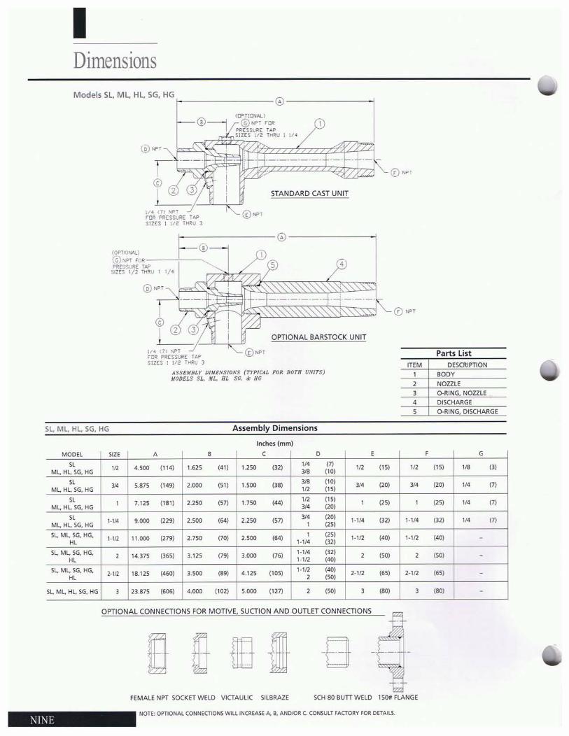
IDimensionsModels SL, ML, Hl, SG, HG.t- @ _
@NPT
I~~©! 2
(OPTm"~L'
@""t FORPRESSLRE TAPSilts 1/2 lliRU 1 1/4
.'
STANDARD CAST UNIT
0 NP1
1/4 0) NPTrOR P!l($SURE TAPSIZES 1 I/~ IHIW 3
0 NP1
Parts listDESCRIPTION
BODY
NOZZLE
ITfM,2
0 NPT
45
OPTIONAL BARSTOCK UNIT
,.__._.~-_._..~._._._.
®...,
F-----@----~-®=JI .
1/4 ell Wi,OR PRESSURC TAPSIIES 1 1/<' THRU J
ASSEMBLY Pl/1lt:NS10.\I$ (TYPICAL I'Of/. BOTH UNITS)MODELS SL••WL, HL $r;, ~ He
(OP11l)N.O,L)
(G) NPT ,ORPF<r'>SVlilE lAl'
SIZES 1/2 THllV 1 II'
@Nl>r
34
5
D-RING, NOZZLE
DISCHARGED·RING, DISCHARGE
5l, Ml, HL, SG, HG Assembly Dimensions
Inches (mm)
MODEL SIZE A • C 0 , , G
" '" 4.500 (114) 1.62$ (41) 1.250 (]21,,,
'" '" (IS) ,n (15) ,. '31ML HL SG. HG '" (TO)
" .. 5.875 {149} 2000 (51) 1.500 (38) '" (lO) YO (20) YO IIO) ,,,'"ML, HL, SG, HG ,n (lS)
" , 7.125 (lSl) 2.250 (57) 1.750 'M',n (TS) , (2S) , (25) '" '"ML HL SG. HG "' (20)
" ,.1/. '.000 (229) 2.500 '64' 2.250 (57) "' (20)1·114 (32) 1·1/4 (32) ,,,
'"ML HL SG, HG , (25)
SL ML, SG, HG.1-1/2 11.000 (279) 2.7S0 (70) 2500 '64'
, (25)1·112 (40) 1·112 (40)
"' 1·1/4 (32) -SL ML SG. HG. , 14.37S (365) 3.125 "" 3.000 (76)
1-1/4 (32)2 (50) 2 (SO)
"' 1_1/2 (40) -SL ML SG. HG.
2·1/2 18.125 (460) 3.500 (89) 4.125 (10S)1_1/2 (40)
2·112 (65) 2·1/2 (65)
"' 2 (50) -
SL ML HL SG. HG 3 23875 (606) '.000 (102) 5000 (127) 2 (50) 3 (80) 3 ''''' -
OPTIONAL CONNECTIONS FOR MOTIVE, SUCTION AND OUTLET CONNECTIONS
if] li1 llfl IlhJ W- ID .
FEMALE NPT SOCKET WELD VICTAULIC SIL8RAZE SCH 80 BUTT WELD 15011 FLANGE
NOTE' OPTIONAL CONN1:CTlONS WILL INCREASE A. 8. AND/OR (. CONSULT FACTORY FOR DETAILS.
NINI·
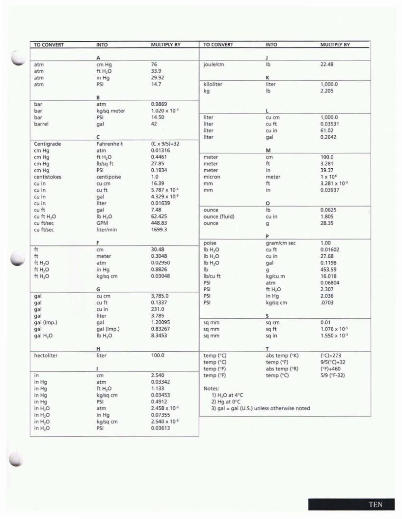
I TOCONVERT INTO MUlTIPLY BY TO CONVERT INTO MUlTIPLY BY
A Jotm emHg 7. joule/em 'b 22.48otm ft H10 33.9otm in Hg 29.92 Kotm PS' 14.7 kiloliter liter 1,000.0kg 'b 2.205
Bbot otm 0.9869..., kglsq meter 1.020 x 10" L..., PS' 14.50 liter eu em 1,000.0barrel g.' 42 litet wn 0.03531
liter co in 61.02C liter g.' 0.2642
Centigrade Fahrenheit (C x 915)+32em Hg otm 0.01316 Mem Hg tt H10 0.4461 meter <m 100.0em Hg Iblsq ft 27.85 meter n 3.281em Hg PS' 0.1934 meter '" 39.37centistokes centipoise 1.0 micron meter 1 x 10'cu in co em 16.39 mm n 3.281)( 10')cu in wn 5.787 x 10" mm '" 0.03937cu in g.' 4.329 x 10·l
cu in liter 0.01639 0<un g.' 7.48 ounce 'b 0.0625cu tt H,O IbH,O 62.425 oun<:e (fluid) cu in 1.805cu ftfse<: GPM 448.83 ounce g 28.35wMe< liter/min 1699.3
PF poise gram/em se<: 1.00
n <m 30.48 IbH20 wn 0.01602n meter 0.3048 IbH20 eu in 27.68tt H,O otm 0.02950 IbHIO g.' 0.1198tt HIO in Hg 0.8826 'b g 453.59tt HIO kglsq em 0.03048 Ibleu ft kg/eu m 16.018
PS' otm 0.06804G PS' ft HIO 2.307
g.' eu em 3,785.0 PS' in Hg 2.036
g.' wn 0.1337 PS' kg/sq em .0703
g.' co in 231.0
g.' liter 3.785 Sgal (Imp.) g.' 1.20095 sq mm sq em 0.01
g.' gal (Imp.) 0.83267 sq mm ,q n 1.076)( 10"gal H,O Ib H2O 8.3453 sq mm sq in 1.550 x 10')
H Thectoliter liter 100.0 temp (OC) abs temp (OK) (°C)+273
temp (oq temp fF) 9JS(eC)+32I temp (OF) i1bs temp (OR) (°F)+460
'" <m 2.540 temp (OF) temp (O() 519 (OF-32)inHg otm 0.03342inHg ft H10 1.133 Notes:inHg kglsq em 0.03453 1) H10 at 4°CinHg PS' 0.4912 2) Hg at O°CinHIO otm 2.458 x 10') 3) gal", gal (U.S.) unless otherwise notedinH,O in Hg 0.07355inH,O kglsq em 2.540 x 10')inH,O PS' 0.03613
TH\

8~.". ""....... " .. ,..
JERGUSON®/JACOBY·TARBOX®
OMstOnS ol The CrarI<'Re!lar>ce Cotporatoon
STRONGSVILLE, OHIO 44136 U.S.A.(216) 572-1500 FAX (216) 238--8828
ISO 9001 CERTIFIED