Embed Size (px)
Citation preview
JET Manual 30Multipurpose Single-Pump
Units, MPS-341, MPF-331, 341
Version 1.0
JET Manual 30 Multipurpose Single-Pump Units MPS-341, MPF-331, 341 InTouch Content ID# 4221768 Version: 1.0 Release Date: Januray 31, 2007 Owner: Well Services Training & Development, IPC
Schlumberger private
Document Control
Revision History
Rev Effective Date Description Prepared by
Copyright © 2007 Schlumberger, Unpublished work. All rights reserved.This work contains the confidential and proprietary trade secrets of Schlumberger and may not be copied or stored in an information retrieval system, transferred, used, distributed, translated, or retransmitted in any form or by any means, electronic or mechanical, in whole or in part, without the express written permission of the copyright owner.
Trademarks & service marks“Schlumberger,” the Schlumberger logotype, and other words or symbols used to identify the products and services described herein are either trademarks, trade names, or service marks of Schlumberger and its licensors, or are the property of their respective owners. These marks may not be copied, imitated or used, in whole or in part, without the express prior written permission of Schlumberger. In addition, covers, page headers, custom graphics, icons, and other design elements may be service marks, trademarks, and/or trade dress of Schlumberger, and may not be copied, imitated, or used, in whole or in part, without the express prior written permission of Schlumberger. A complete list of Schlumberger marks may be viewed at the Schlumberger Oilfield Services Marks page: http://www.hub.slb.com/index.cfm?id=id32083
An asterisk (*) is used throughout this document to designate a mark of Schlumberger.
Other company, product, and service names are the properties of their respective owners.
iiiJET 30 - Multipurpose Single-Pump Units MPS-341, MPF-331, 341 |
TableofContents
1.0 Introduction 71.1 Learning objectives 71.2 Scope of manual 7
2.0 Key Safety and Services Quality Requirements 92.1 Safety 92.2 Service quality 10
3.0 Units Overview 133.1 Equipment coding 143.2 Applications 153.3 Specifications 15
4.0 Major Components 175.0 Skid-Mounted Components MPS-341 19
5.1 MPS-341 engine 215.1.1 Coolingsystem 215.1.2 Airsystem 215.1.3 Electricsystem 225.1.4 Emergencyshutdownsystem 225.1.5 Soundlevels 23
5.2 MPS-341 control console 235.2.1 Mainpowerdisconnectcontrol 235.2.3 Uppercontrolconsole 265.2.4 MPS-341clutchandtransmissioncontrols 275.2.5 Dataacquisitionandmonitoring 28
5.3 MPS-341 process piping 295.3.1 High-pressurelines 295.3.2 Low-pressurelines 29
6.0 Components MPF-331 and MPF-341 316.1 Trailer 326.2 Tractor 32
6.2.1 Engine 336.2.2 Coolingsystem 356.2.3 Airsystem 35
iv | Table of Contents
6.2.4 Electricsystemandstarter 356.2.5 Emergencykillswitch 35
6.3 MPF-331 control console 366.3.1 Upperconsole 376.3.2 Lowerconsole 386.3.3 Clutchandtransmissioncontrols 406.3.4 Dataacquisitionandmonitoring 41
6.4 Process piping (MPF-331) 426.4.1 High-pressurelines 446.4.2 Low-pressurelines 45
6.5 Displacement (tote) tanks 466.6 Acid (cargo) tanks 47
7.0 Major Components Common to all Multipurpose Pump Units 497.1 Transmission and gear selection 497.2 Triplex pump 53
7.2.1 Generalspecifications 547.2.2 Powerendandgearreducer 547.2.3 Fluidends 567.2.4 Fluidendpacking 57
7.3 Centrifugal pumps 627.4 Lubrication system: fluid-end and C-pump 63
8.0 Unit Inspections 658.1 Inspections before leaving the district 658.2 Prejob and postjob inspections (STEM 1) 65
9.0 Arrival on Location 779.1 Positioning equipment on location 779.2 Fluid supply hook-up 779.3 Data acquisition hook-up 789.4 High-pressure discharge hook-up 78
10.0 Starting Up, Priming, and Pressure Testing 7910.1 Starting the engines 7910.2 Priming the unit and testing the overpressure shutdowns 80
10.2.1 PrimingtheMPS-341unit 8010.2.2 PrimingMPF-331andMPF-341units 82
10.3 Pressure and line testing 8511.0 Pumping Operation Procedures 87
11.1 General considerations 8711.2 Pump rate selection 88
vJET 30 - Multipurpose Single-Pump Units MPS-341, MPF-331, 341 |
11.3 Pumping downhole 9011.3.1 Genericprocedures 9011.3.2 Washingupandriggingdowntoleavethelocation 90
11.4 Shutting down and leaving location 9211.5 Cold weather operations 9211.6 Special tasks specific to the MPF-331 and 341 units 93
11.6.1 Mixingandcirculatingthedisplacementtankcontents 9311.6.2 Mixingandcirculatingtheacidtankcontents 94
12.0 Leaving the Location 9513.0 Troubleshooting 9714.0 Maintenance Procedures 9915.0 References 101
15.1 Oilfield Services QHSE standards 10115.2 Well Services safety standards 10115.3 JET manuals 10115.4 Unit manuals 101
16.0 Appendix: Forms 10317.0 Check Your Understanding 111

vi | Table of Contents
This page left intentionally blank
7JET 30 - Multipurpose Single-Pump Units MPS-341, MPF-331, 341 |
1.0 Introduction
This jpb execution training (JET) manual introduces you to a series of multipurpose single pump units for use in operations that require extended pump times at low rates and high pressures. These conditions are typical of coiled tubing (CT) operations. Three pump units are discussed in this manual:
MPS-341 single pump skid unit
MPF-341 single pump float unit with displacement (tote) tanks
MPF-331 single pump float unit with acid and displacement (tote) tanks.
1.1 Learning objectivesUpon completion of this training manual, you will be able to
describe the main features and principles of operation of the MPS-341, MPF-331, and MPF-341
describe the safety and service quality key requirements
explain the steps of the pretrip, posttrip, and job inspections
explain the steps involved with operating the unit (priming, pressure testing, mixing fluids, and pumping).
1.2 Scope of manualThis JET manual provides a basic introduction to the subject matter. Because of the scope of the subject, all aspects of operations and maintenance cannot be addressed. References are given in Section 11; refer to these for any additional information.
•
•
•
•
•
•
•
The information in this manual is current at the time of publication. Some components may be updated or changed before a new version of the manual can be issued.

8 | Introduction
This page left intentionally blank
9JET 30 - Multipurpose Single-Pump Units MPS-341, MPF-331, 341 |
2.0 KeySafetyandServicesQualityRequirements
The MPS-341, MPF-331, and MPF-341 units must be operated according to the relevant safety and service quality requirements. These requirements are described in this section and in Section 15, References.
Note:Anyone who believes that an operation is not safe has the right and the duty to stop the operation. It is the responsibility of the equipment operator to ensure that he or she has the knowledge required to complete the job safely.
2.1 SafetyAll three units must be operated according to all applicable Oilfield Services (OFS) and Well Services (WS) safety standards.
Warning:The MPS-341, MPF-331, and MPF-341 have unique pressure testing requirements. Be sure to follow the procedure described in Section 10.
Personnel must be current on OFS and WS relevant quality, health, safety, and environmental (QHSE) standards. All WS employees must be familiar with the Well Services Field Safety Handbook (InTouch Content ID# 3038407). Refer to Section 15, References, in this JET for a complete list of applicable safety standards.
Personnel must use appropriate, clean, and functional personal protective equipment (PPE) when operating and performing maintenance on the unit. The required PPE is described in Schlumberger OFS QHSE Standard S003: Personal Protective Equipment, InTouch Content ID# 3260259. The following items are required to be worn for all pumping operations:
NOMEX™ coveralls (long sleeves)
hard-toed boots
hard hat
safety glasses (or goggles, as required)
ear protection
gloves (work or rubber, as required)
dust masks and face shields (as required).
Note:Ear plugs are not sufficient hearing protection: ear muffs must be worn when operating a unit. In addition to ear muffs, sound-reducing panels must be in place. With this protection, operators who have not experienced hearing damage are allowed to work 12-hr shifts.
Ensure that all safety devices are in place and operational before performing any operation. The covers and guards installed on this unit should not be removed or modified.
Ensure all nonessential personnel stay away from the unit during operation.
•
•
•
•
•
•
•
10 | Key Safety and Services Quality Requirements
Contain and clean all chemical spills and report them according to local procedures.
Be aware of all moving parts on the unit while it is running, such as the mixer area, engines, and drive shafts. If you must climb onto the unit, be very careful. The exhaust lines, hydraulic lines, and some parts of the engine get very hot during operation and can cause severe burns.
Warning:Do not climb onto the engine while it is running.
The MPS-341 can be used only in safe areas and hazardous areas classified as CSA Class I, Division 2, Group D, T3.
Note:Modifications to the mechanical and electrical systems may void this certification and thus are not allowed without written approval from Wellsite Delivery Department or Equipment Supply Coordination.
2.2 Service qualityJob supervisors and equipment operators must have completed training and be judged competent by the line manager for the operations performed. Certain operational procedures of this unit may differ from those of other pumping units and should be discussed during the training of new operators.
Proper supervision is required during hands-on training. As your supervisor for help if you are unfamiliar or uncomfortable with any operation.
Ensure that the following tasks are done:
Equipment is maintained according to established procedures. It should be current on standard equipment maintenance (STEM I and II) inspections, and equipment must be cleaned and painted to Schlumberger standards.
All treating equipment is inspected and tested according to WS Safety Standard 23: Testing and Inspection of Treating Equipment, InTouch Content ID# 3313701.
The equipment required for the job as designed is available and complies with the relevant QHSE standards.
The equipment is rigged up on location and operated according to the relevant WS standards.
Follow WS Safety Standard 5: Pressure Pumping and Location Safety, InTouch Content ID# 3313681, and the hook-up and operating guidelines for all pumping operations.
Always allow enough time to ensure that the prejob and postjob checks can be done correctly. Items omitted from a check are opportunities for accidents and equipment failures.
Record critical job parameters (rates and pressures), and make sure that the required sample collections are performed during a job.
The job team (operator and crew) should discuss and be familiar with the following topics before beginning a job:
the service quality risk assessment
the job design and procedures
job sheets with relevant well information
contingency planning in case something goes wrong.
•
•
•
•
•
•
•
•
11JET 30 - Multipurpose Single-Pump Units MPS-341, MPF-331, 341 |
Note:Be aware of any other unsafe situations and hazards during operations and routine maintenance. Correct and report unsafe hazards or service quality incidents promptly.

12 | Key Safety and Services Quality Requirements
This page left intentionally blank
13JET 30 - Multipurpose Single-Pump Units MPS-341, MPF-331, 341 |
3.0 UnitsOverview
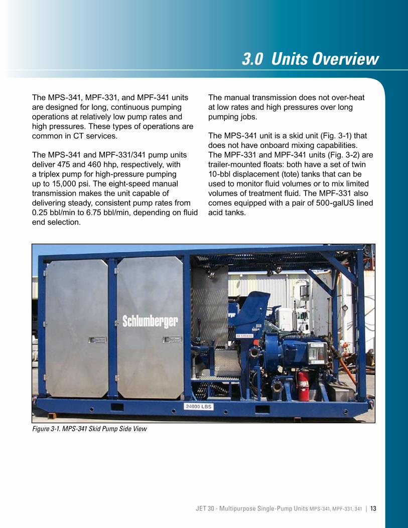
The MPS-341, MPF-331, and MPF-341 units are designed for long, continuous pumping operations at relatively low pump rates and high pressures. These types of operations are common in CT services.
The MPS-341 and MPF-331/341 pump units deliver 475 and 460 hhp, respectively, with a triplex pump for high-pressure pumping up to 15,000 psi. The eight-speed manual transmission makes the unit capable of delivering steady, consistent pump rates from 0.25 bbl/min to 6.75 bbl/min, depending on fluid end selection.
Figure 3-1. MPS-341 Skid Pump Side View
The manual transmission does not over-heat at low rates and high pressures over long pumping jobs.
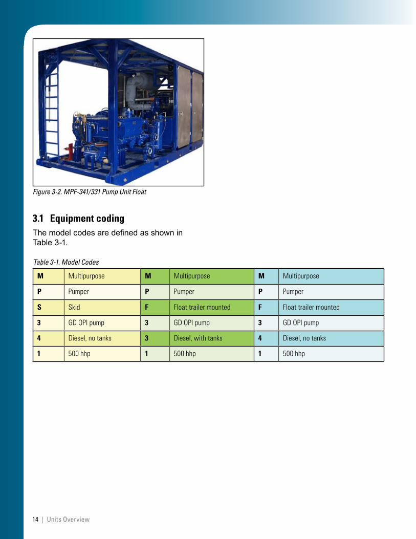
The MPS-341 unit is a skid unit (Fig. 3-1) that does not have onboard mixing capabilities. The MPF-331 and MPF-341 units (Fig. 3-2) are trailer-mounted floats: both have a set of twin 10-bbl displacement (tote) tanks that can be used to monitor fluid volumes or to mix limited volumes of treatment fluid. The MPF-331 also comes equipped with a pair of 500-galUS lined acid tanks.
14 | Units Overview
Figure 3-2. MPF-341/331 Pump Unit Float
3.1 Equipment codingThe model codes are defined as shown in Table 3-1.
M Multipurpose M Multipurpose M Multipurpose
P Pumper P Pumper P Pumper
S Skid F Floattrailermounted F Floattrailermounted
3 GDOPIpump 3 GDOPIpump 3 GDOPIpump
4 Diesel,notanks 3 Diesel,withtanks 4 Diesel,notanks
1 500hhp 1 500hhp 1 500hhp
Table 3-1. Model Codes
15JET 30 - Multipurpose Single-Pump Units MPS-341, MPF-331, 341 |
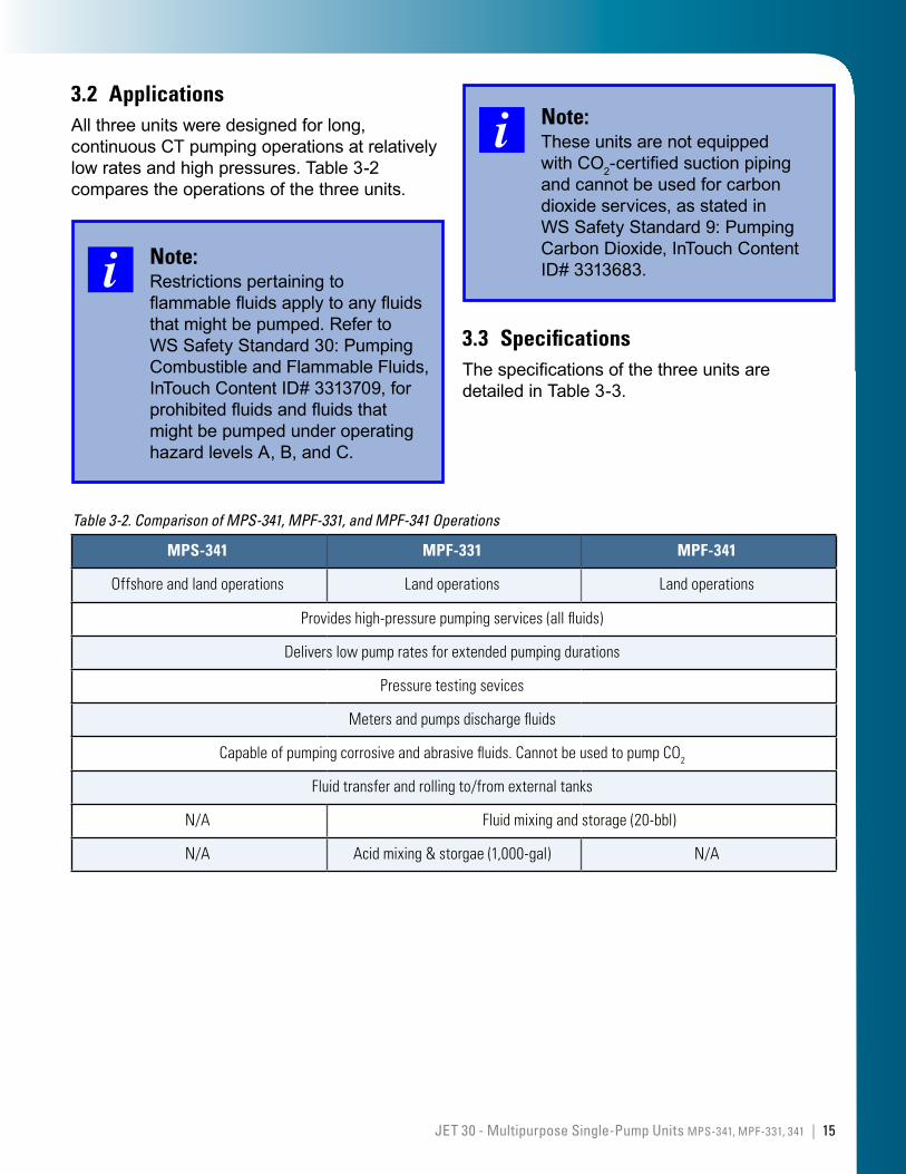
3.2 ApplicationsAll three units were designed for long, continuous CT pumping operations at relatively low rates and high pressures. Table 3-2 compares the operations of the three units.
Note:Restrictions pertaining to flammable fluids apply to any fluids that might be pumped. Refer to WS Safety Standard 30: Pumping Combustible and Flammable Fluids, InTouch Content ID# 3313709, for prohibited fluids and fluids that might be pumped under operating hazard levels A, B, and C.
MPS-341 MPF-331 MPF-341
Offshoreandlandoperations Landoperations Landoperations
Provideshigh-pressurepumpingservices(allfluids)
Deliverslowpumpratesforextendedpumpingdurations
Pressuretestingsevices
Metersandpumpsdischargefluids
Capableofpumpingcorrosiveandabrasivefluids.CannotbeusedtopumpCO2
Fluidtransferandrollingto/fromexternaltanks
N/A Fluidmixingandstorage(20-bbl)
N/A Acidmixing&storgae(1,000-gal) N/A
Table 3-2. Comparison of MPS-341, MPF-331, and MPF-341 Operations
Note:These units are not equipped with CO2-certified suction piping and cannot be used for carbon dioxide services, as stated in WS Safety Standard 9: Pumping Carbon Dioxide, InTouch Content ID# 3313683.
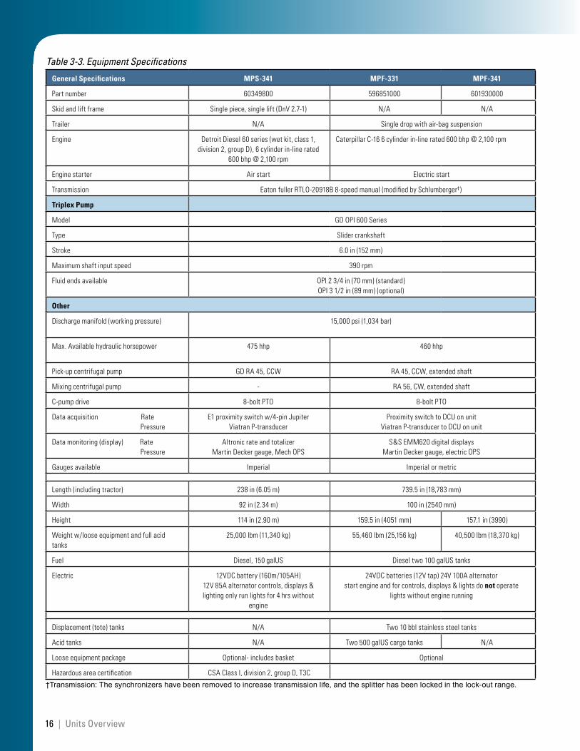
3.3 SpecificationsThe specifications of the three units are detailed in Table 3-3.
16 | Units Overview
General Specifications MPS-341 MPF-331 MPF-341
Partnumber 60349800 596851000 601930000
Skidandliftframe Singlepiece,singlelift(DnV2.7-1) N/A N/A
Trailer N/A Singledropwithair-bagsuspension
Engine DetroitDiesel60series(wetkit,class1,division2,groupD),6cylinderin-linerated
600bhp@2,100rpm
CaterpillarC-166cylinderin-linerated600bhp@2,100rpm
Enginestarter Airstart Electricstart
Transmission EatonfullerRTLO-20918B8-speedmanual(modifiedbySchlumberger†)
Triplex Pump
Model GDOPI600Series
Type Slidercrankshaft
Stroke 6.0in(152mm)
Maximumshaftinputspeed 390rpm
Fluidendsavailable OPI23/4in(70mm)(standard)OPI31/2in(89mm)(optional)
Other
Dischargemanifold(workingpressure) 15,000psi(1,034bar)
Max.Availablehydraulichorsepower 475hhp 460hhp
Pick-upcentrifugalpump GDRA45,CCW RA45,CCW,extendedshaft
Mixingcentrifugalpump - RA56,CW,extendedshaft
C-pumpdrive 8-boltPTO 8-boltPTO
Dataacquisition Rate Pressure
E1proximityswitchw/4-pinJupiterViatranP-transducer
ProximityswitchtoDCUonunitViatranP-transducertoDCUonunit
Datamonitoring(display) Rate Pressure
AltronicrateandtotalizerMartinDeckergauge,MechOPS
S&SEMM620digitaldisplaysMartinDeckergauge,electricOPS
Gaugesavailable Imperial Imperialormetric
Length(includingtractor) 238in(6.05m) 739.5in(18,783mm)
Width 92in(2.34m) 100in(2540mm)
Height 114in(2.90m) 159.5in(4051mm) 157.1in(3990)
Weightw/looseequipmentandfullacidtanks
25,000lbm(11,340kg) 55,460lbm(25,156kg) 40,500lbm(18,370kg)
Fuel Diesel,150galUS Dieseltwo100galUStanks
Electric 12VDCbattery(160m/105AH)12V85Aalternatorcontrols,displays&lightingonlyrunlightsfor4hrswithout
engine
24VDCbatteries(12Vtap)24V100Aalternatorstartengineandforcontrols,displays&lightsdonotoperate
lightswithoutenginerunning
Displacement(tote)tanks N/A Two10bblstainlesssteeltanks
Acidtanks N/A Two500galUScargotanks N/A
Looseequipmentpackage Optional-includesbasket Optional
Hazardousareacertification CSAClassI,division2,groupD,T3C
†Transmission: The synchronizers have been removed to increase transmission life, and the splitter has been locked in the lock-out range.
Table 3-3. Equipment Specifications
17JET 30 - Multipurpose Single-Pump Units MPS-341, MPF-331, 341 |
4.0 MajorComponents
For each unit, an engine provides the power to operate the centrifugal (C-) pumps and the triplex pump.
A clutch in the transmission connects and disconnects the engine from the triplex pump. The clutch also disengages the engine when the gears are being shifted. The gear that is selected determines the pump speed (rate) and pressure.
A C-pump boosts the fluid supply to the triplex pump and can be used to transfer and mix fluids in external tanks and in the displacement and acid tanks on the float units. A second C-pump is used on the float pump units as a make-up pump to take on fluids to the displacement tanks.
The triplex pump converts the rotational power of the engine to the reciprocating motion of the pump plungers and pushes the fluid being pumped. The triplex pump is a positive-displacement, reciprocating pump that can generate very high pressures.
The major components for each unit are described in the following sections of the manual:
Section 5 discusses the MPS-341 skid-mounted unit.
skid
engine and associated systems (cooling, electric, and air)
control console
process piping (high and low pressure).
•
•
•
•
Section 6 discusses the MPF-331 and MPF-341 trailer-mounted units:
trailer
engine and associated systems (cooling, electric, and air)
control console
tanks (displacement and acid tanks)
process piping (high and low pressure).
In Section 7: Components common to all three units
transmission
triplex pump (including power-end and gear reducer)
lubrication systems (pumps and power trains)
C-pumps.
•
•
•
•
•
•
•
•
•

This page left intentionally blank
18 | Major Components
19JET 30 - Multipurpose Single-Pump Units MPS-341, MPF-331, 341 |
5.0 Skid-MountedComponentsMPS-341
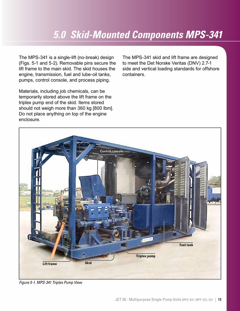
The MPS-341 is a single-lift (no-break) design (Figs. 5-1 and 5-2). Removable pins secure the lift frame to the main skid. The skid houses the engine, transmission, fuel and lube-oil tanks, pumps, control console, and process piping.
Materials, including job chemicals, can be temporarily stored above the lift frame on the triplex pump end of the skid. Items stored should not weigh more than 360 kg [800 lbm]. Do not place anything on top of the engine enclosure.
Figure 5-1. MPS-341 Triplex Pump View
Control console
Lift frame
Triplex pump
Skid
Fuel tank
The MPS-341 skid and lift frame are designed to meet the Det Norske Veritas (DNV) 2.7-1 side and vertical loading standards for offshore containers.
20 | Skid-Mounted Components MPS-341
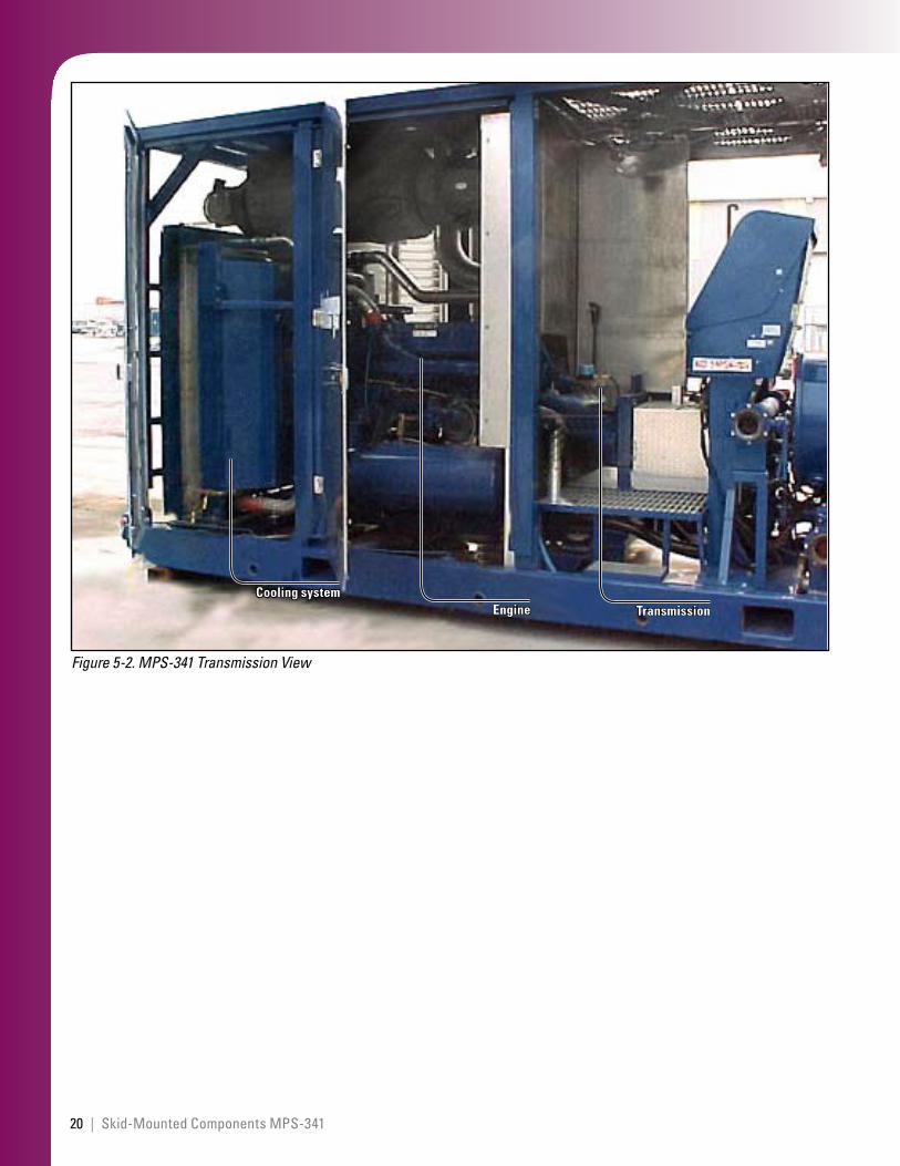
Figure 5-2. MPS-341 Transmission View
TransmissionEngineCooling system
21JET 30 - Multipurpose Single-Pump Units MPS-341, MPF-331, 341 |
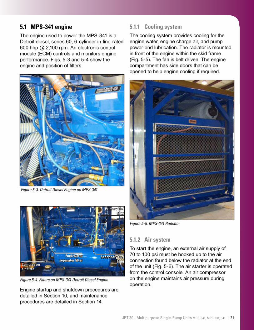
5.1 MPS-341 engineThe engine used to power the MPS-341 is a Detroit diesel, series 60, 6-cylinder in-line-rated 600 hhp @ 2,100 rpm. An electronic control module (ECM) controls and monitors engine performance. Figs. 5-3 and 5-4 show the engine and position of filters.
Figure 5-3. Detroit Diesel Engine on MPS-341
Figure 5-4. Filters on MPS-341 Detroit Diesel Engine
Primary fuel filter
Compressor air filter
Fuel/water separator filter
Secondary fuel filter
Engine startup and shutdown procedures are detailed in Section 10, and maintenance procedures are detailed in Section 14.
5.1.1 Cooling systemThe cooling system provides cooling for the engine water, engine charge air, and pump power-end lubrication. The radiator is mounted in front of the engine within the skid frame (Fig. 5-5). The fan is belt driven. The engine compartment has side doors that can be opened to help engine cooling if required.
Figure 5-5. MPS-341 Radiator
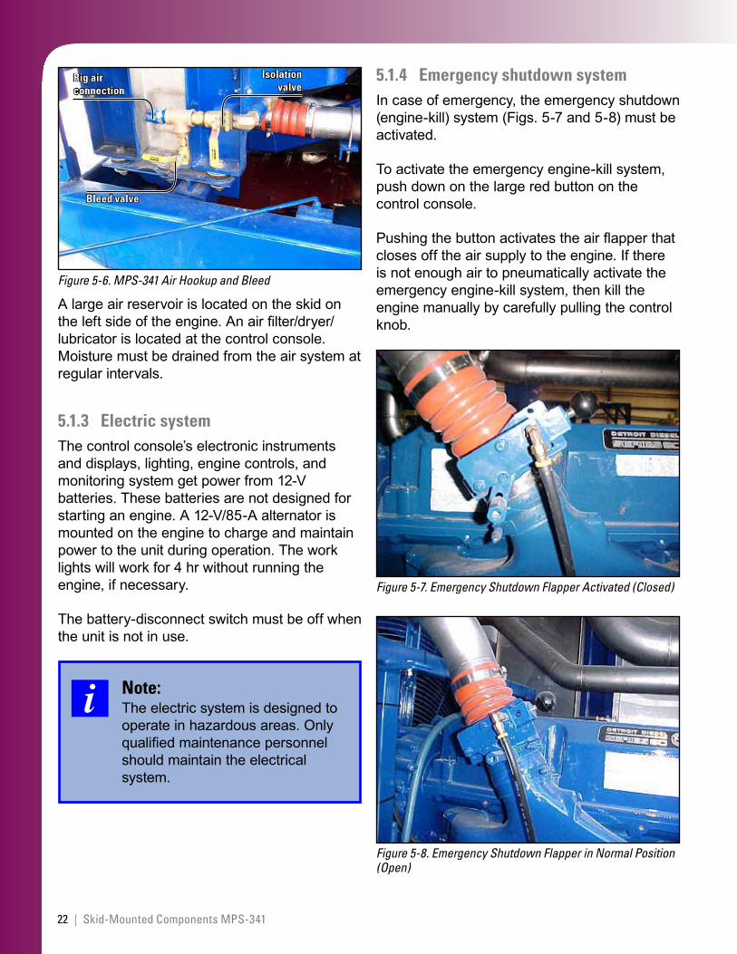
5.1.2 Air systemTo start the engine, an external air supply of 70 to 100 psi must be hooked up to the air connection found below the radiator at the end of the unit (Fig. 5-6). The air starter is operated from the control console. An air compressor on the engine maintains air pressure during operation.
22 | Skid-Mounted Components MPS-341
Figure 5-6. MPS-341 Air Hookup and Bleed
Isolation valve
Bleed valve
Rig air connection
A large air reservoir is located on the skid on the left side of the engine. An air filter/dryer/lubricator is located at the control console. Moisture must be drained from the air system at regular intervals.
5.1.3 Electric systemThe control console’s electronic instruments and displays, lighting, engine controls, and monitoring system get power from 12-V batteries. These batteries are not designed for starting an engine. A 12-V/85-A alternator is mounted on the engine to charge and maintain power to the unit during operation. The work lights will work for 4 hr without running the engine, if necessary.
The battery-disconnect switch must be off when the unit is not in use.
Note:The electric system is designed to operate in hazardous areas. Only qualified maintenance personnel should maintain the electrical system.
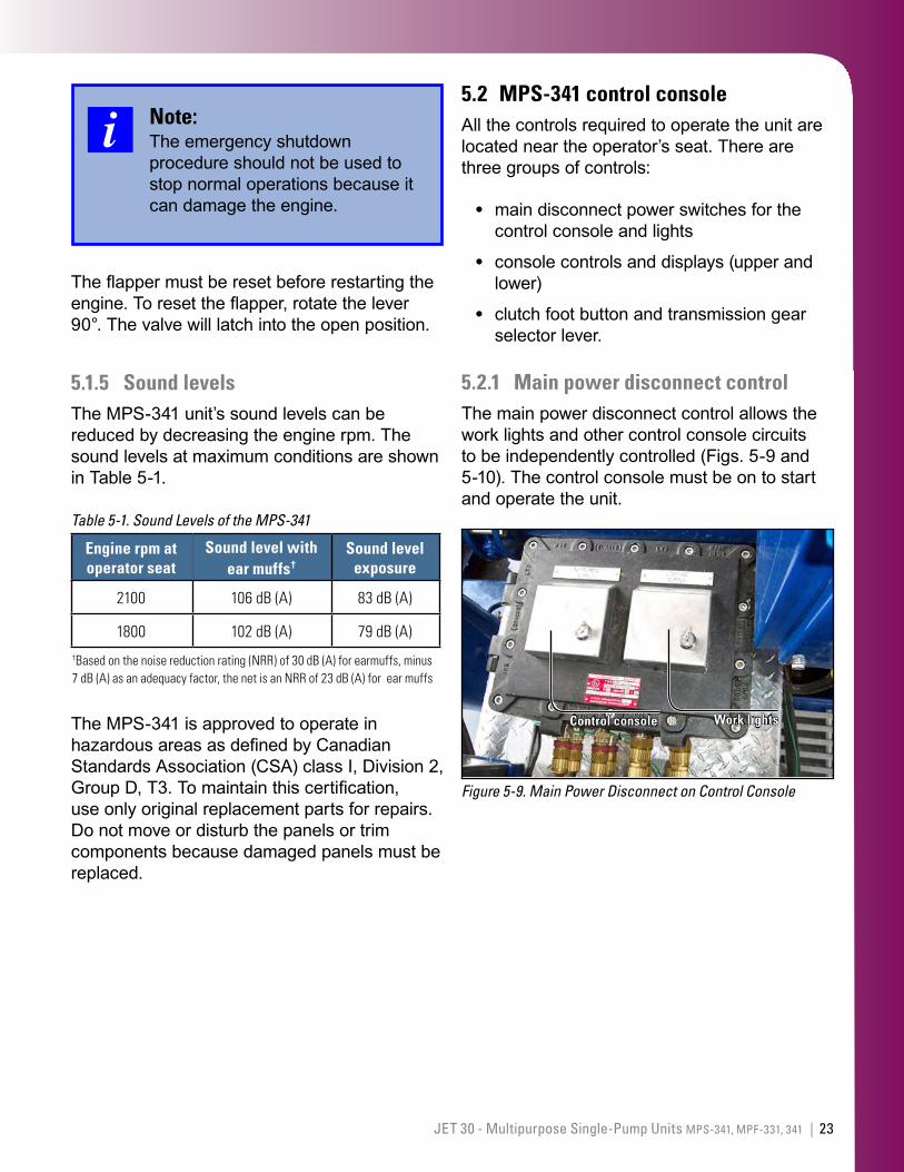
5.1.4 Emergency shutdown systemIn case of emergency, the emergency shutdown (engine-kill) system (Figs. 5-7 and 5-8) must be activated.
To activate the emergency engine-kill system, push down on the large red button on the control console.
Pushing the button activates the air flapper that closes off the air supply to the engine. If there is not enough air to pneumatically activate the emergency engine-kill system, then kill the engine manually by carefully pulling the control knob.
Figure 5-7. Emergency Shutdown Flapper Activated (Closed)
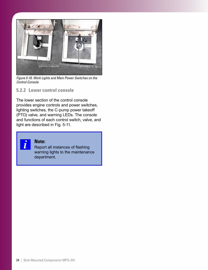
Figure 5-8. Emergency Shutdown Flapper in Normal Position (Open)
23JET 30 - Multipurpose Single-Pump Units MPS-341, MPF-331, 341 |
Note:The emergency shutdown procedure should not be used to stop normal operations because it can damage the engine.
The flapper must be reset before restarting the engine. To reset the flapper, rotate the lever 90°. The valve will latch into the open position.
5.1.5 Sound levelsThe MPS-341 unit’s sound levels can be reduced by decreasing the engine rpm. The sound levels at maximum conditions are shown in Table 5-1.
Table 5-1. Sound Levels of the MPS-341
Engine rpm at operator seat
Sound level with ear muffs†
Sound level exposure
2100 106dB(A) 83dB(A)
1800 102dB(A) 79dB(A)†Basedonthenoisereductionrating(NRR)of30dB(A)forearmuffs,minus7dB(A)asanadequacyfactor,thenetisanNRRof23dB(A)forearmuffs
The MPS-341 is approved to operate in hazardous areas as defined by Canadian Standards Association (CSA) class I, Division 2, Group D, T3. To maintain this certification, use only original replacement parts for repairs. Do not move or disturb the panels or trim components because damaged panels must be replaced.
5.2 MPS-341 control console All the controls required to operate the unit are located near the operator’s seat. There are three groups of controls:
main disconnect power switches for the control console and lights
console controls and displays (upper and lower)
clutch foot button and transmission gear selector lever.
5.2.1 Main power disconnect controlThe main power disconnect control allows the work lights and other control console circuits to be independently controlled (Figs. 5-9 and 5-10). The control console must be on to start and operate the unit.
Figure 5-9. Main Power Disconnect on Control Console
Control console Work lights
•
•
•
24 | Skid-Mounted Components MPS-341
Figure 5-10. Work Lights and Main Power Switches on the Control Console
Control console Work lights
5.2.2 Lower control console
The lower section of the control console provides engine controls and power switches, lighting switches, the C-pump power takeoff (PTO) valve, and warning LEDs. The console and functions of each control switch, valve, and light are described in Fig. 5-11.
Note:Report all instances of flashing warning lights to the maintenance department.
25JET 30 - Multipurpose Single-Pump Units MPS-341, MPF-331, 341 |
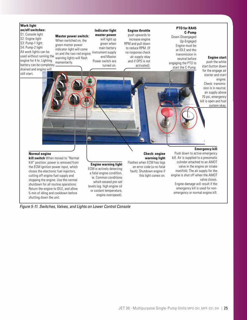
Figure 5-11. Switches, Valves, and Lights on Lower Control Console
Indicator light master power
willlightupgreenwhen
mainbatteryinstrumentsupply
andMasterPowerswitchare
turnedon.
Engine throttle pushupwardstoincreaseengine
RPMandpulldowntoreduceRPM.(Ifnoresponsecheck
airsupplyokayandifOPSisnot
activated).
PTO for RA45 C-Pump
Down-DisengagedUp-Engaged
EnginemustbeatIDLEandthetransmissioninneutralbefore
engagingthePTOtostarttheC-Pump.
Engine start pushthewhite
startbuttondownfortheengageair
starterandstartengine.
Check:transmis-sionisinneutral,airsupplyabove
70psi,emergencykillisopenandfuel
systemokay.
Emergency kill Pushdowntoactiveemergency
kill.AirissuppliedtoapneumaticcylinderattachedtoanAMOT
valveintheengineairintakemanifold.Theairsupplyforthe
engineisshutoffwhentheAMOTvalvecloses.
Enginedamagewillresultiftheemergencykillisusedfornon-
emergencyornormalenginekill.
Master power switch: Whenswitchedon,thegreenmasterpowerindicatorlightwillcomeonandthetworedenginewarninglightswillflashmomentarily.
Normal engine kill switch Whenmovedto“NormalKill”position,powerisremovedfromtheECMignitionpowerinput,whichclosestheelectronicfuelinjectors,cuttingoffenginefuelsupplyandstoppingtheengine.Usethenormalshutdownforallroutineoperations.ReturntheenginetoIDLE,andallow5-minofidlingandcooldownbeforeshuttingdowntheunit.
Engine warning light ECMisactivelydetecting
afatalenginecondition,ie.Commonconditions
whichexceedpre-setlevels(eg.highengineoil
orcoolanttemperature,engineoverspeed).
Check: engine warning light
FlasheswhenECMhaslogsanerrorcode(ano-fatal
fault).Shutdownengineifthislightcomeson.
Work light on/off switches: S1:ConsolelightS2:EnginelightS3:Pump-1lightS4:Pump-2lightAllworklightscanbeusedwithoutrunningtheenginefor4hr.Lightingbatterycanbecompleteydrainedandenginewillstillstart.
26 | Skid-Mounted Components MPS-341
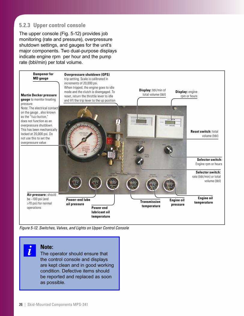
5.2.3 Upper control console The upper console (Fig. 5-12) provides job monitoring (rate and pressure), overpressure shutdown settings, and gauges for the unit’s major components. Two dual-purpose displays indicate engine rpm per hour and the pump rate (bbl/min) per total volume.
Figure 5-12. Switches, Valves, and Lights on Upper Control Console
Selector switch: rate(bbl/min)ortotal
volume(bbl)
Power end lubricant oil temperature
Engine oil pressure
Transmission temperature
Power-end lube oil pressure
Martin Decker pressure gauge tomonitortreatingpressureNote:Theelectricalcontactonthegauge,alsoknownasthe“fuzzbutton,”doesnotfunctionasanoverpressureshutdown.Thishasbeenmechanicallylockedat20,000psi.Donotusethistosettheoverpressurevalue
Dampener for MD gauge
Display: bbl/minoftotalvolume(bbl)
Overpressure shutdown (OPS) tripsetting.Scaleiscalibratedinincrementsof20,000psi.Whentripped,theenginegoestoidlemodeandtheclutchisdisengaged.Toreset,returnthethrottlelevertoidleandliftthetriplevertotheupposition
Display: enginerpmorhours
Reset switch: totalvolume(bbl)
Engine oil temperature
Air pressure:shouldbe~100psi(and>70psi)fornormaloperations
Selector switch: Engine rpmorhours
Note:The operator should ensure that the control console and displays are kept clean and in good working condition. Defective items should be reported and replaced as soon as possible.
27JET 30 - Multipurpose Single-Pump Units MPS-341, MPF-331, 341 |
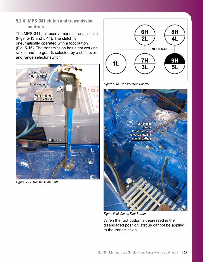
5.2.4 MPS-341 clutch and transmission controls
The MPS-341 unit uses a manual transmission (Figs. 5-13 and 5-14). The clutch is pneumatically operated with a foot button (Fig. 5-15). The transmission has eight working ratios, and the gear is selected by a shift lever and range selector switch.
Figure 5-13. Transmission Shift
Range selector (high position)
Range selector
Range selector (low position)
Shift lever
Figure 5-14. Transmission Control
Figure 5-15. Clutch Foot Button
Clutch foot button
Press button to release clutch to
enable shifting
When the foot button is depressed in the disengaged position, torque cannot be applied to the transmission.
28 | Skid-Mounted Components MPS-341
When the foot button is released to the engaged position, torque is applied by the engine to the transmission via the clutch plate. The pump is connected directly to the transmission and will begin rotating as soon as the clutch is engaged after the transmission is placed in gear.
Note:The transmission must be in neutral to start the engine and to engage a PTO.
Selection and changing of gears are discussed in Section 7.1.1.
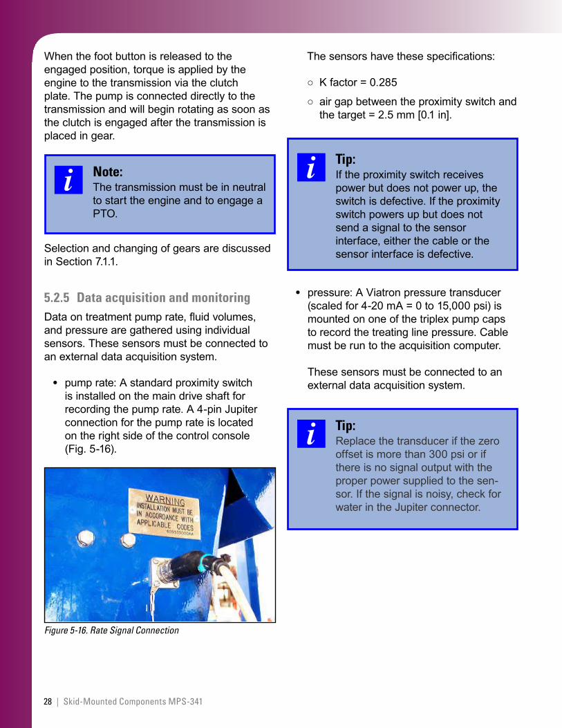
5.2.5 Data acquisition and monitoringData on treatment pump rate, fluid volumes, and pressure are gathered using individual sensors. These sensors must be connected to an external data acquisition system.
pump rate: A standard proximity switch is installed on the main drive shaft for recording the pump rate. A 4-pin Jupiter connection for the pump rate is located on the right side of the control console (Fig. 5-16).
Figure 5-16. Rate Signal Connection
•
The sensors have these specifications:
K factor = 0.285
air gap between the proximity switch and the target = 2.5 mm [0.1 in].
Tip:If the proximity switch receives power but does not power up, the switch is defective. If the proximity switch powers up but does not send a signal to the sensor interface, either the cable or the sensor interface is defective.
pressure: A Viatron pressure transducer (scaled for 4-20 mA = 0 to 15,000 psi) is mounted on one of the triplex pump caps to record the treating line pressure. Cable must be run to the acquisition computer. These sensors must be connected to an external data acquisition system.
Tip:Replace the transducer if the zero offset is more than 300 psi or if there is no signal output with the proper power supplied to the sen-sor. If the signal is noisy, check for water in the Jupiter connector.
○
○
•
29JET 30 - Multipurpose Single-Pump Units MPS-341, MPF-331, 341 |
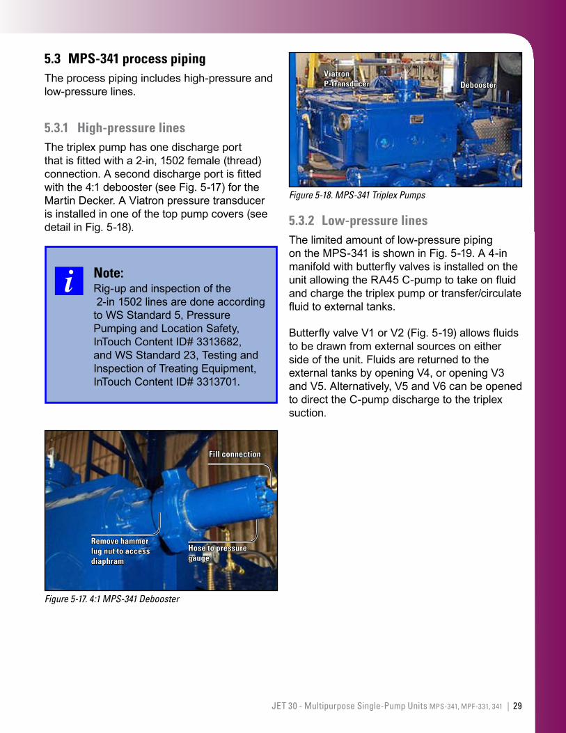
5.3 MPS-341 process pipingThe process piping includes high-pressure and low-pressure lines.
5.3.1 High-pressure linesThe triplex pump has one discharge port that is fitted with a 2-in, 1502 female (thread) connection. A second discharge port is fitted with the 4:1 debooster (see Fig. 5-17) for the Martin Decker. A Viatron pressure transducer is installed in one of the top pump covers (see detail in Fig. 5-18).
Note:Rig-up and inspection of the 2-in 1502 lines are done according to WS Standard 5, Pressure Pumping and Location Safety, InTouch Content ID# 3313682, and WS Standard 23, Testing and Inspection of Treating Equipment, InTouch Content ID# 3313701.
Figure 5-17. 4:1 MPS-341 Debooster
Fill connection
Hose to pressure gauge
Remove hammer lug nut to access diaphram
Figure 5-18. MPS-341 Triplex Pumps
Viatron P-transducer Debooster
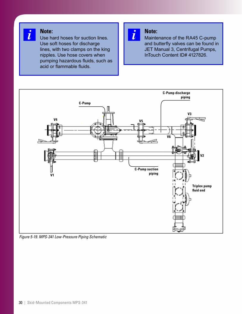
5.3.2 Low-pressure linesThe limited amount of low-pressure piping on the MPS-341 is shown in Fig. 5-19. A 4-in manifold with butterfly valves is installed on the unit allowing the RA45 C-pump to take on fluid and charge the triplex pump or transfer/circulate fluid to external tanks.
Butterfly valve V1 or V2 (Fig. 5-19) allows fluids to be drawn from external sources on either side of the unit. Fluids are returned to the external tanks by opening V4, or opening V3 and V5. Alternatively, V5 and V6 can be opened to direct the C-pump discharge to the triplex suction.
30 | Skid-Mounted Components MPS-341
Note:Use hard hoses for suction lines. Use soft hoses for discharge lines, with two clamps on the king nipples. Use hose covers when pumping hazardous fluids, such as acid or flammable fluids.
Figure 5-19. MPS-341 Low-Pressure Piping Schematic
C-Pump
C-Pump suction piping
Triplex pump fluid end
C-Pump discharge piping
V5
V3
V2
V6
V4
V1
Note:Maintenance of the RA45 C-pump and butterfly valves can be found in JET Manual 3, Centrifugal Pumps, InTouch Content ID# 4127826.
31JET 30 - Multipurpose Single-Pump Units MPS-341, MPF-331, 341 |
6.0 ComponentsMPF-331andMPF-341
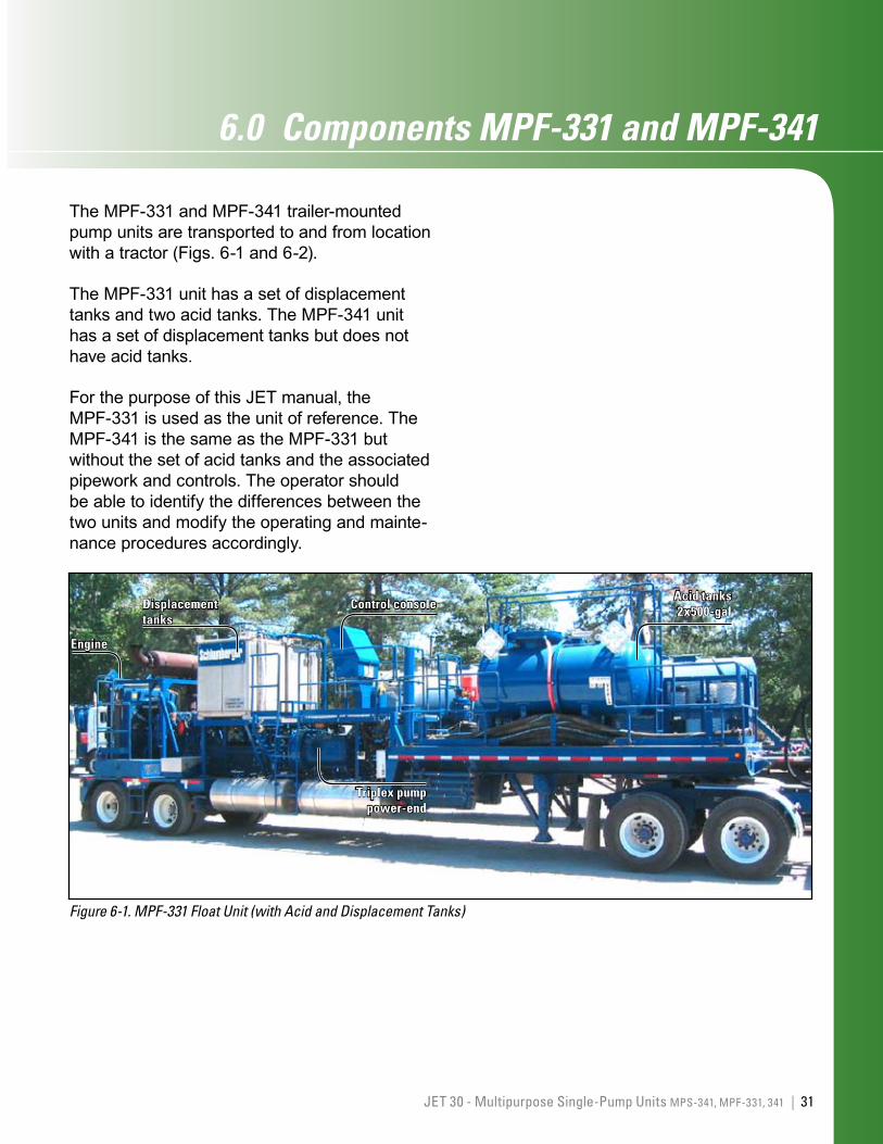
The MPF-331 and MPF-341 trailer-mounted pump units are transported to and from location with a tractor (Figs. 6-1 and 6-2).
The MPF-331 unit has a set of displacement tanks and two acid tanks. The MPF-341 unit has a set of displacement tanks but does not have acid tanks.
For the purpose of this JET manual, the MPF-331 is used as the unit of reference. The MPF-341 is the same as the MPF-331 but without the set of acid tanks and the associated pipework and controls. The operator should be able to identify the differences between the two units and modify the operating and mainte-nance procedures accordingly.
Figure 6-1. MPF-331 Float Unit (with Acid and Displacement Tanks)
Control consoleDisplacement tanks
Triplex pump power-end
Engine
Acid tanks 2x500-gal
32 | Multipurpose Pumper Float (MPF-331 and MPF-341)
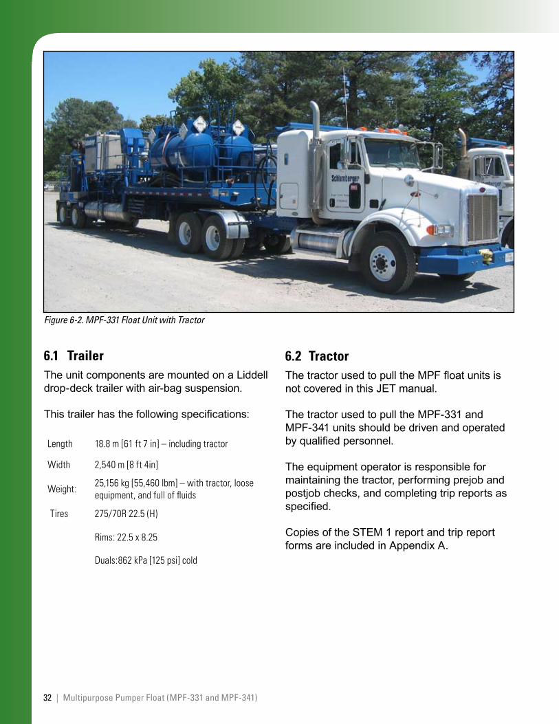
Figure 6-2. MPF-331 Float Unit with Tractor
6.1 TrailerThe unit components are mounted on a Liddell drop-deck trailer with air-bag suspension.
This trailer has the following specifications:
Length 18.8m[61ft7in]–includingtractor
Width 2,540m[8ft4in]
Weight: 25,156kg[55,460lbm]–withtractor,looseequipment,andfulloffluids
Tires 275/70R22.5(H)
Rims:22.5x8.25
Duals:862kPa[125psi]cold
6.2 TractorThe tractor used to pull the MPF float units is not covered in this JET manual.
The tractor used to pull the MPF-331 and MPF-341 units should be driven and operated by qualified personnel.
The equipment operator is responsible for maintaining the tractor, performing prejob and postjob checks, and completing trip reports as specified.
Copies of the STEM 1 report and trip report forms are included in Appendix A.
33JET 30 - Multipurpose Single-Pump Units MPS-341, MPF-331, 341 |
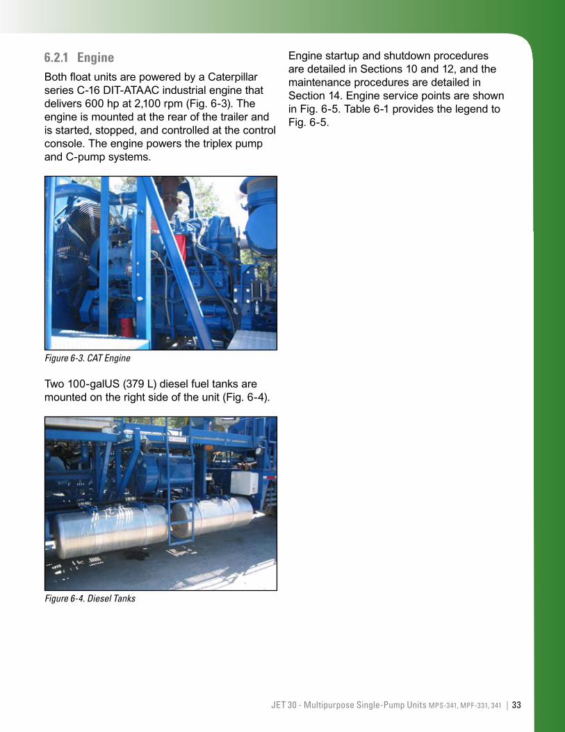
6.2.1 EngineBoth float units are powered by a Caterpillar series C-16 DIT-ATAAC industrial engine that delivers 600 hp at 2,100 rpm (Fig. 6-3). The engine is mounted at the rear of the trailer and is started, stopped, and controlled at the control console. The engine powers the triplex pump and C-pump systems.
Figure 6-3. CAT Engine
Two 100-galUS (379 L) diesel fuel tanks are mounted on the right side of the unit (Fig. 6-4).
Figure 6-4. Diesel Tanks
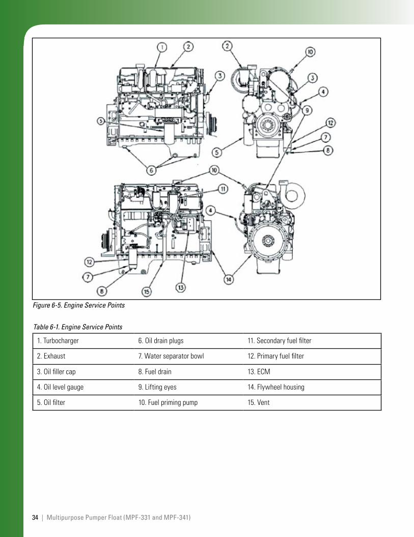
Engine startup and shutdown procedures are detailed in Sections 10 and 12, and the maintenance procedures are detailed in Section 14. Engine service points are shown in Fig. 6-5. Table 6-1 provides the legend to Fig. 6-5.
34 | Multipurpose Pumper Float (MPF-331 and MPF-341)
Figure 6-5. Engine Service Points
1.Turbocharger 6.Oildrainplugs 11.Secondaryfuelfilter
2.Exhaust 7.Waterseparatorbowl 12.Primaryfuelfilter
3.Oilfillercap 8.Fueldrain 13.ECM
4.Oillevelgauge 9.Liftingeyes 14.Flywheelhousing
5.Oilfilter 10.Fuelprimingpump 15.Vent
Table 6-1. Engine Service Points
35JET 30 - Multipurpose Single-Pump Units MPS-341, MPF-331, 341 |
6.2.2 Cooling systemThe cooling system cools the engine water, engine charge air, and pump power-end lubrication. The radiator is mounted at the rear of the trailer chassis. The fan is belt driven.
6.2.3 Air systemA gear-driven air compressor mounted on the engine supplies air to the control console. You can maintain air pressure from the console only by keeping the engine running. Allow a few minutes after normal engine startup for the air pressure to build to 70 to 100 psi.
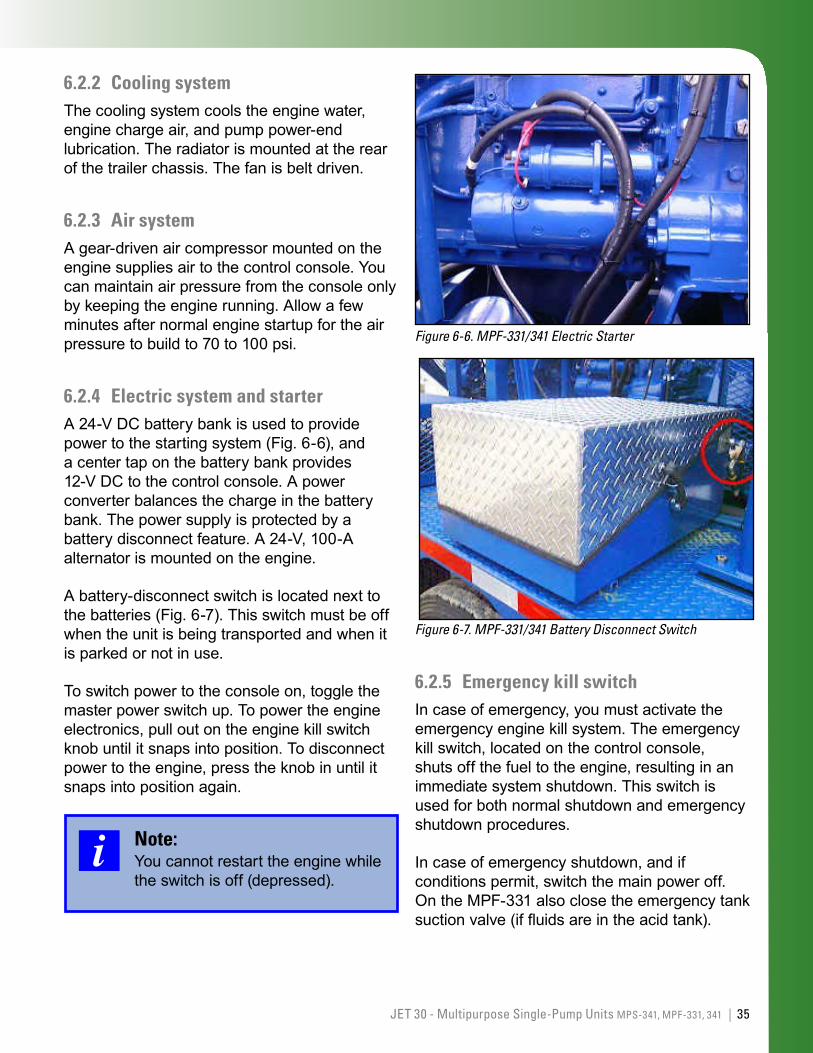
6.2.4 Electric system and starterA 24-V DC battery bank is used to provide power to the starting system (Fig. 6-6), and a center tap on the battery bank provides 12-V DC to the control console. A power converter balances the charge in the battery bank. The power supply is protected by a battery disconnect feature. A 24-V, 100-A alternator is mounted on the engine.
A battery-disconnect switch is located next to the batteries (Fig. 6-7). This switch must be off when the unit is being transported and when it is parked or not in use.
To switch power to the console on, toggle the master power switch up. To power the engine electronics, pull out on the engine kill switch knob until it snaps into position. To disconnect power to the engine, press the knob in until it snaps into position again.
Note:You cannot restart the engine while the switch is off (depressed).
Figure 6-6. MPF-331/341 Electric Starter
Figure 6-7. MPF-331/341 Battery Disconnect Switch
6.2.5 Emergency kill switchIn case of emergency, you must activate the emergency engine kill system. The emergency kill switch, located on the control console, shuts off the fuel to the engine, resulting in an immediate system shutdown. This switch is used for both normal shutdown and emergency shutdown procedures.
In case of emergency shutdown, and if conditions permit, switch the main power off. On the MPF-331 also close the emergency tank suction valve (if fluids are in the acid tank).
36 | Multipurpose Pumper Float (MPF-331 and MPF-341)
You can restart the engine by using the normal engine start procedure.
Note:After the unit has been shut down using the emergency kill switch, always follow the appropriate on-location emergency procedures.
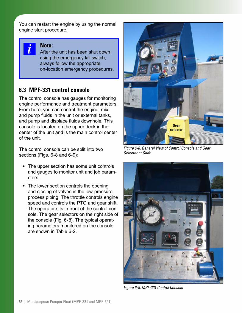
6.3 MPF-331 control console The control console has gauges for monitoring engine performance and treatment parameters. From here, you can control the engine, mix and pump fluids in the unit or external tanks, and pump and displace fluids downhole. This console is located on the upper deck in the center of the unit and is the main control center of the unit.
The control console can be split into two sections (Figs. 6-8 and 6-9):
The upper section has some unit controls and gauges to monitor unit and job param-eters.
The lower section controls the opening and closing of valves in the low-pressure process piping. The throttle controls engine speed and controls the PTO and gear shift. The operator sits in front of the control con-sole. The gear selectors on the right side of the console (Fig. 6-8). The typical operat-ing parameters monitored on the console are shown in Table 6-2.
•
•
Figure 6-8. General View of Control Console and Gear Selector or Shift
Gear selector
Figure 6-9. MPF-331 Control Console
37JET 30 - Multipurpose Single-Pump Units MPS-341, MPF-331, 341 |
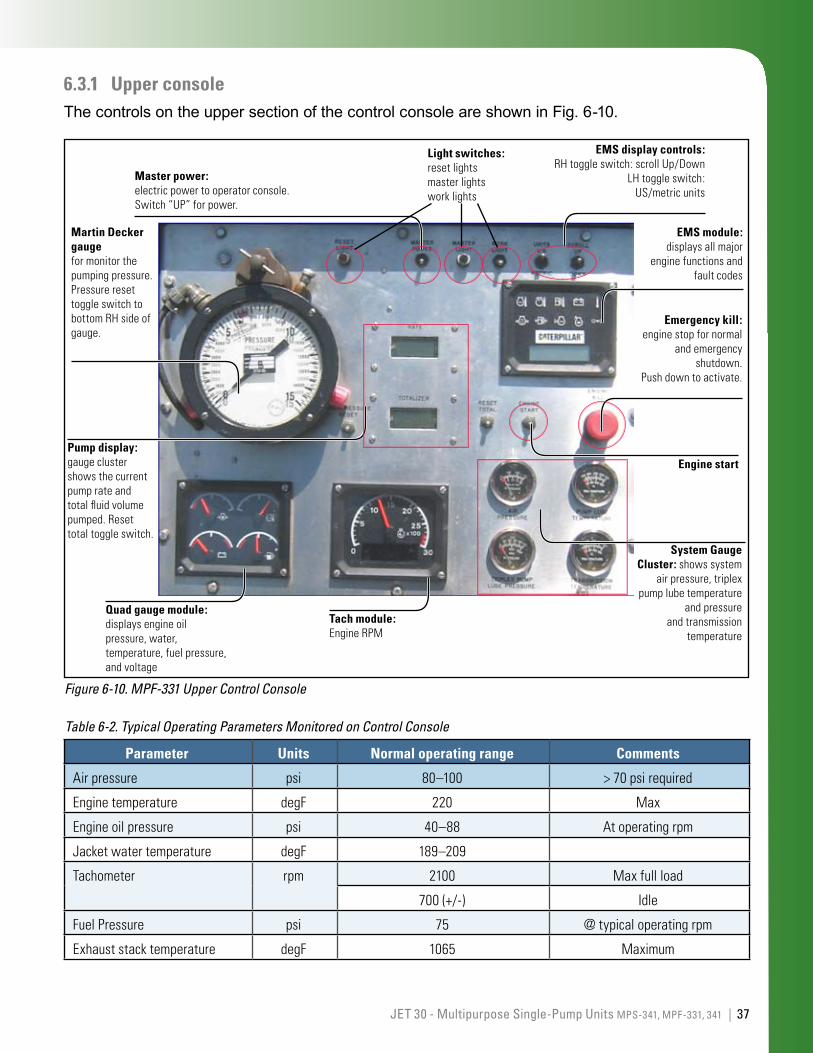
6.3.1 Upper consoleThe controls on the upper section of the control console are shown in Fig. 6-10.
Figure 6-10. MPF-331 Upper Control Console
EMS display controls: RHtoggleswitch:scrollUp/Down
LHtoggleswitch:US/metricunits
Quad gauge module: displaysengineoilpressure,water,temperature,fuelpressure,andvoltage
Master power:electricpowertooperatorconsole.Switch“UP”forpower.
Light switches:resetlightsmasterlightsworklights
EMS module: displaysallmajor
enginefunctionsandfaultcodes
Emergency kill: enginestopfornormal
andemergencyshutdown.
Pushdowntoactivate.
Pump display: gaugeclustershowsthecurrentpumprateandtotalfluidvolumepumped.Resettotaltoggleswitch.
Engine start
System Gauge Cluster:showssystem
airpressure,triplexpumplubetemperature
andpressureandtransmission
temperatureTach module: EngineRPM
Martin Decker gauge formonitorthepumpingpressure.PressureresettoggleswitchtobottomRHsideofgauge.
Parameter Units Normal operating range Comments
Airpressure psi 80–100 >70psirequired
Enginetemperature degF 220 Max
Engineoilpressure psi 40–88 Atoperatingrpm
Jacketwatertemperature degF 189–209
Tachometer rpm 2100 Maxfullload
700(+/-) Idle
FuelPressure psi 75 @typicaloperatingrpm
Exhauststacktemperature degF 1065 Maximum
Table 6-2. Typical Operating Parameters Monitored on Control Console
38 | Multipurpose Pumper Float (MPF-331 and MPF-341)
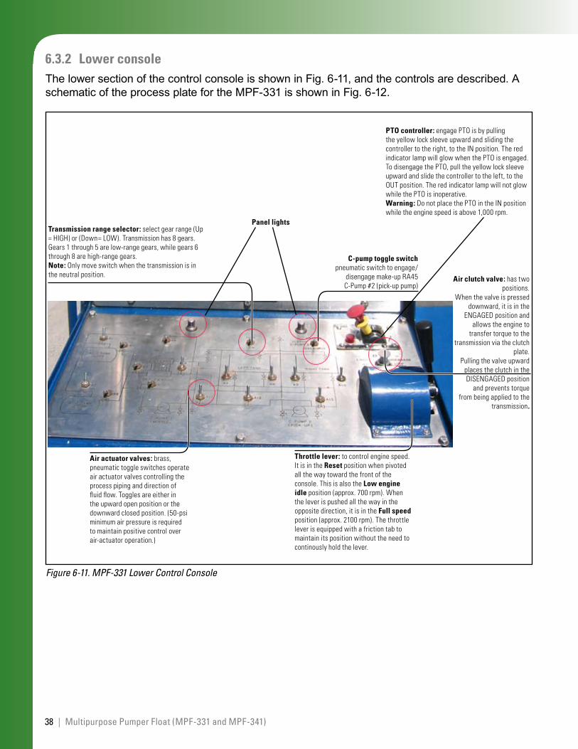
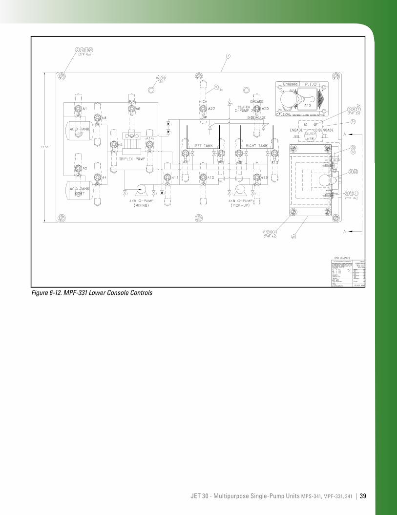
6.3.2 Lower consoleThe lower section of the control console is shown in Fig. 6-11, and the controls are described. A schematic of the process plate for the MPF-331 is shown in Fig. 6-12.
Figure 6-11. MPF-331 Lower Control Console
C-pump toggle switch pneumaticswitchtoengage/
disengagemake-upRA45C-Pump#2(pick-uppump)
Air actuator valves:brass,pneumatictoggleswitchesoperateairactuatorvalvescontrollingtheprocesspipinganddirectionoffluidflow.Togglesareeitherintheupwardopenpositionorthedownwardclosedposition.(50-psiminimumairpressureisrequiredtomaintainpositivecontroloverair-actuatoroperation.)
Transmission range selector:selectgearrange(Up=HIGH)or(Down=LOW).Transmissionhas8gears.Gears1through5arelow-rangegears,whilegears6through8arehigh-rangegears.Note:Onlymoveswitchwhenthetransmissionisintheneutralposition.
Panel lights
Air clutch valve: hastwopositions.
Whenthevalveispresseddownward,itisinthe
ENGAGEDpositionandallowstheengineto
transfertorquetothetransmissionviatheclutch
plate.Pullingthevalveupward
placestheclutchintheDISENGAGEDposition
andpreventstorquefrombeingappliedtothe
transmission.
Throttle lever: tocontrolenginespeed.Itisinthe Reset positionwhenpivotedallthewaytowardthefrontoftheconsole.ThisisalsotheLow engine idle position(approx.700rpm).Whentheleverispushedallthewayintheoppositedirection,itisintheFull speedposition(approx.2100rpm).Thethrottleleverisequippedwithafrictiontabtomaintainitspositionwithouttheneedtocontinouslyholdthelever.
PTO controller: engagePTOisbypullingtheyellowlocksleeveupwardandslidingthecontrollertotheright,totheINposition.TheredindicatorlampwillglowwhenthePTOisengaged.TodisengagethePTO,pulltheyellowlocksleeveupwardandslidethecontrollertotheleft,totheOUTposition.TheredindicatorlampwillnotglowwhilethePTOisinoperative.Warning:DonotplacethePTOintheINpositionwhiletheenginespeedisabove1,000rpm.
39JET 30 - Multipurpose Single-Pump Units MPS-341, MPF-331, 341 |
Figure 6-12. MPF-331 Lower Console Controls
40 | Multipurpose Pumper Float (MPF-331 and MPF-341)
6.3.3 Clutch and transmission controlsLike the MPS-341, the MPF-331 and 341 use a manual transmission. The method of engaging and disengaging the transmission is different, however.
Note:The transmission must be in neutral to start the engine and to engage a PTO.
The clutch is pneumatically operated by using a push/pull button on the lower control console. The transmission has eight working ratios.
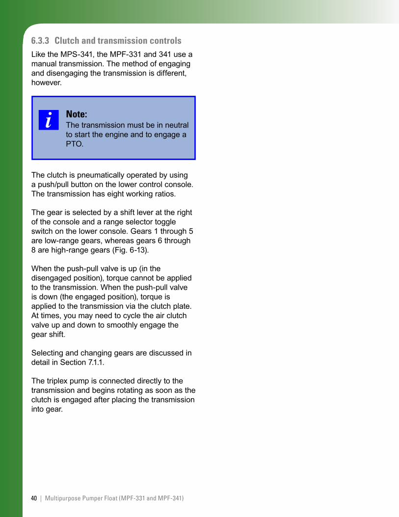
The gear is selected by a shift lever at the right of the console and a range selector toggle switch on the lower console. Gears 1 through 5 are low-range gears, whereas gears 6 through 8 are high-range gears (Fig. 6-13).
When the push-pull valve is up (in the disengaged position), torque cannot be applied to the transmission. When the push-pull valve is down (the engaged position), torque is applied to the transmission via the clutch plate. At times, you may need to cycle the air clutch valve up and down to smoothly engage the gear shift.
Selecting and changing gears are discussed in detail in Section 7.1.1.
The triplex pump is connected directly to the transmission and begins rotating as soon as the clutch is engaged after placing the transmission into gear.
41JET 30 - Multipurpose Single-Pump Units MPS-341, MPF-331, 341 |
Figure 6-13. Transmission Control and Transmission Shift Pattern
6.3.4 Data acquisition and monitoringTreatment pump rate, fluid volumes, and pressure are acquired using individual sensors.
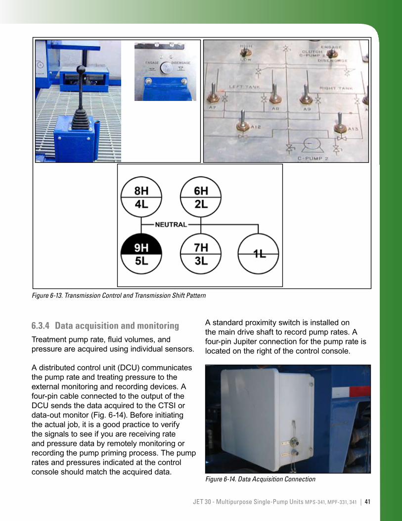
A distributed control unit (DCU) communicates the pump rate and treating pressure to the external monitoring and recording devices. A four-pin cable connected to the output of the DCU sends the data acquired to the CTSI or data-out monitor (Fig. 6-14). Before initiating the actual job, it is a good practice to verify the signals to see if you are receiving rate and pressure data by remotely monitoring or recording the pump priming process. The pump rates and pressures indicated at the control console should match the acquired data.
A standard proximity switch is installed on the main drive shaft to record pump rates. A four-pin Jupiter connection for the pump rate is located on the right of the control console.
Figure 6-14. Data Acquisition Connection
42 | Multipurpose Pumper Float (MPF-331 and MPF-341)
Sensor specifications include the following:
K factor of 0.285
air-gap between the proximity switch and the target of 0.1-in (2.5 mm).
Note:If the proximity switch is receiving power but still does not power up, the switch needs replacing. If the proximity switch powers up but does not send a signal to the sensor interface, either the cable or the sensor interface is defective.
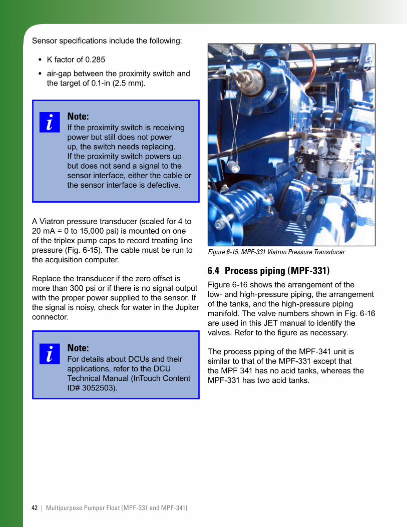
A Viatron pressure transducer (scaled for 4 to 20 mA = 0 to 15,000 psi) is mounted on one of the triplex pump caps to record treating line pressure (Fig. 6-15). The cable must be run to the acquisition computer.
Replace the transducer if the zero offset is more than 300 psi or if there is no signal output with the proper power supplied to the sensor. If the signal is noisy, check for water in the Jupiter connector.
Note:For details about DCUs and their applications, refer to the DCU Technical Manual (InTouch Content ID# 3052503).
•
•
Figure 6-15. MPF-331 Viatron Pressure Transducer
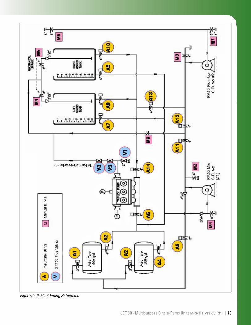
6.4 Process piping (MPF-331) Figure 6-16 shows the arrangement of the low- and high-pressure piping, the arrangement of the tanks, and the high-pressure piping manifold. The valve numbers shown in Fig. 6-16 are used in this JET manual to identify the valves. Refer to the figure as necessary.
The process piping of the MPF-341 unit is similar to that of the MPF-331 except that the MPF 341 has no acid tanks, whereas the MPF-331 has two acid tanks.
43JET 30 - Multipurpose Single-Pump Units MPS-341, MPF-331, 341 |
Figure 6-16. Float Piping Schematic
44 | Multipurpose Pumper Float (MPF-331 and MPF-341)
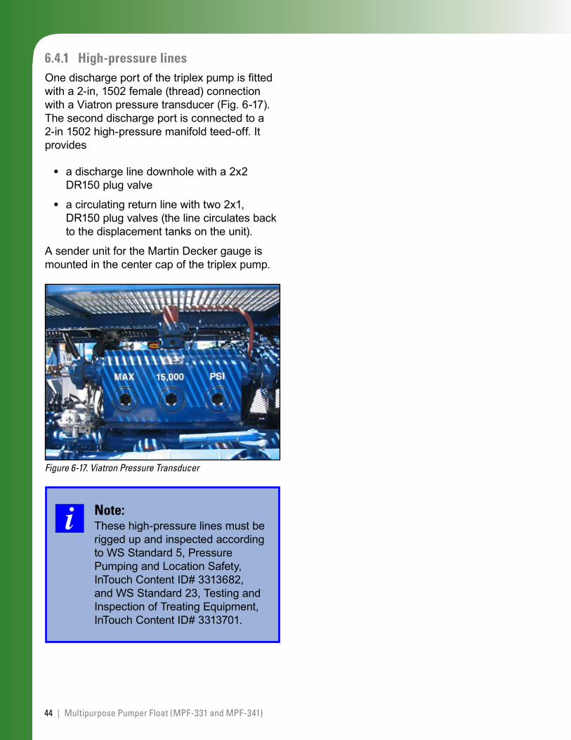
6.4.1 High-pressure linesOne discharge port of the triplex pump is fitted with a 2-in, 1502 female (thread) connection with a Viatron pressure transducer (Fig. 6-17). The second discharge port is connected to a 2-in 1502 high-pressure manifold teed-off. It provides
a discharge line downhole with a 2x2 DR150 plug valve
a circulating return line with two 2x1, DR150 plug valves (the line circulates back to the displacement tanks on the unit).
A sender unit for the Martin Decker gauge is mounted in the center cap of the triplex pump.
Figure 6-17. Viatron Pressure Transducer
Note:These high-pressure lines must be rigged up and inspected according to WS Standard 5, Pressure Pumping and Location Safety, InTouch Content ID# 3313682, and WS Standard 23, Testing and Inspection of Treating Equipment, InTouch Content ID# 3313701.
•
•
45JET 30 - Multipurpose Single-Pump Units MPS-341, MPF-331, 341 |
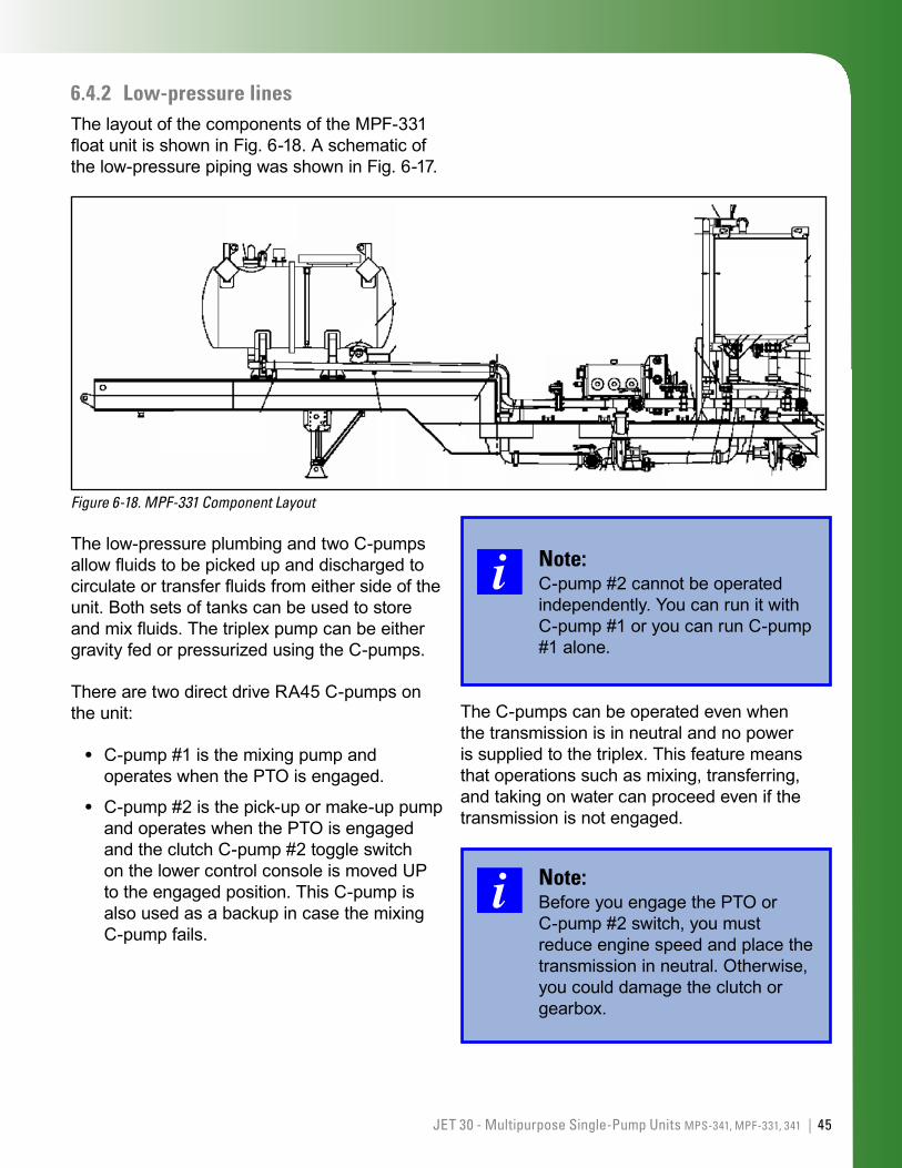
6.4.2 Low-pressure linesThe layout of the components of the MPF-331 float unit is shown in Fig. 6-18. A schematic of the low-pressure piping was shown in Fig. 6-17.
Figure 6-18. MPF-331 Component Layout
The low-pressure plumbing and two C-pumps allow fluids to be picked up and discharged to circulate or transfer fluids from either side of the unit. Both sets of tanks can be used to store and mix fluids. The triplex pump can be either gravity fed or pressurized using the C-pumps.
There are two direct drive RA45 C-pumps on the unit:
C-pump #1 is the mixing pump and operates when the PTO is engaged.
C-pump #2 is the pick-up or make-up pump and operates when the PTO is engaged and the clutch C-pump #2 toggle switch on the lower control console is moved UP to the engaged position. This C-pump is also used as a backup in case the mixing C-pump fails.
•
•
Note:C-pump #2 cannot be operated independently. You can run it with C-pump #1 or you can run C-pump #1 alone.
The C-pumps can be operated even when the transmission is in neutral and no power is supplied to the triplex. This feature means that operations such as mixing, transferring, and taking on water can proceed even if the transmission is not engaged.
Note:Before you engage the PTO or C-pump #2 switch, you must reduce engine speed and place the transmission in neutral. Otherwise, you could damage the clutch or gearbox.
46 | Multipurpose Pumper Float (MPF-331 and MPF-341)
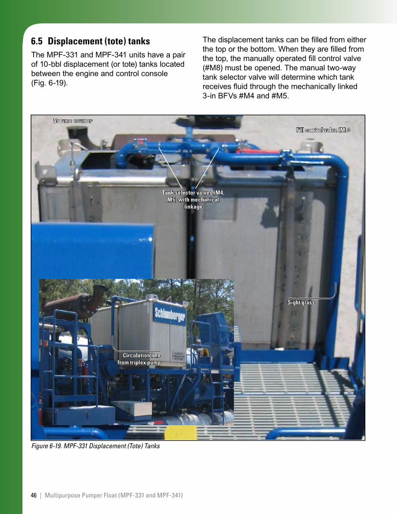
6.5 Displacement (tote) tanksThe MPF-331 and MPF-341 units have a pair of 10-bbl displacement (or tote) tanks located between the engine and control console (Fig. 6-19).
Figure 6-19. MPF-331 Displacement (Tote) Tanks
Circulation line from triplex pump
Sight glass
Tank selector valves (M4, M5) with mechanical
linkage
Fill control valve (M8)
Volume counter
The displacement tanks can be filled from either the top or the bottom. When they are filled from the top, the manually operated fill control valve (#M8) must be opened. The manual two-way tank selector valve will determine which tank receives fluid through the mechanically linked 3-in BFVs #M4 and #M5.
47JET 30 - Multipurpose Single-Pump Units MPS-341, MPF-331, 341 |
Note:When you use the displacement tanks to mix or pump hazardous materials or fluids, make sure you use the proper PPE and review the appropriate MSDS sheets.
Make sure the displacement tanks are clean and free of debris before every job.
The procedures on filling, circulating, mixing, and taking on fluids from the displacement tanks are detailed in Sections 10 and 11.
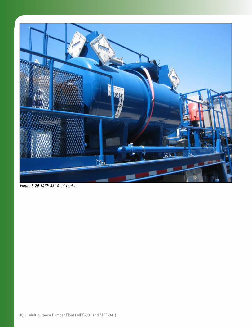
6.6 Acid (cargo) tanksThe MPF-331 has two 500-galUS lined acid (cargo) tanks located at the back of the trailer (Fig. 6-20). These tanks can transport, store, or mix up to 1,000 galUS of acid.
An air actuator for the tank sump valve is located near the acid tanks on the side of the trailer (curbside) to the right of the access ladder. This valve (Fig. 3-1 inset) allows you to manually close the lower access valves to the acid tanks in case of emergency.
The acid tanks can be circulated by using either of the C-pumps. The triplex pump can be either gravity fed from the acid tanks or pressurized using the C-pump.
Any chemical spill must be reported, contained, and cleaned according to local procedures. Please refer to these standards for further information.
WS Safety Standard 17: Storage and Handling of Oxidizers, InTouch Content ID# 3313693.
WS Safety Standard 18: HAZCOM, InTouch Content ID# 3313694.
•
•
Note:Make sure you use the proper PPE and review the appropriate MSDS sheets when you pump acid.
The procedures on filling, circulating, mixing, and taking on fluids from the acid tanks are detailed in Sections 10 and 11.
Note:Clean the acid tanks and piping thoroughly after every job. Do not leave acid in the unit lines or pumps.
48 | Multipurpose Pumper Float (MPF-331 and MPF-341)
Figure 6-20. MPF-331 Acid Tanks
49JET 30 - Multipurpose Single-Pump Units MPS-341, MPF-331, 341 |
7.0 MajorComponentsCommontoallMultipurposePumpUnits
The major components common to all three multipurpose pump units are the transmission, the triplex pump, the C-pumps, and the lubrication system.
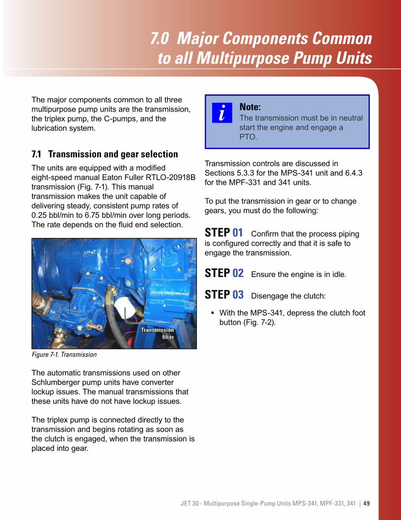
7.1 Transmission and gear selectionThe units are equipped with a modified eight-speed manual Eaton Fuller RTLO-20918B transmission (Fig. 7-1). This manual transmission makes the unit capable of delivering steady, consistent pump rates of 0.25 bbl/min to 6.75 bbl/min over long periods. The rate depends on the fluid end selection.
Figure 7-1. Transmission
Transmission filter
The automatic transmissions used on other Schlumberger pump units have converter lockup issues. The manual transmissions that these units have do not have lockup issues.
The triplex pump is connected directly to the transmission and begins rotating as soon as the clutch is engaged, when the transmission is placed into gear.
Note:The transmission must be in neutral start the engine and engage a PTO.
Transmission controls are discussed in Sections 5.3.3 for the MPS-341 unit and 6.4.3 for the MPF-331 and 341 units.
To put the transmission in gear or to change gears, you must do the following:
STEP 01 Confirm that the process piping is configured correctly and that it is safe to engage the transmission.
STEP 02 Ensure the engine is in idle.
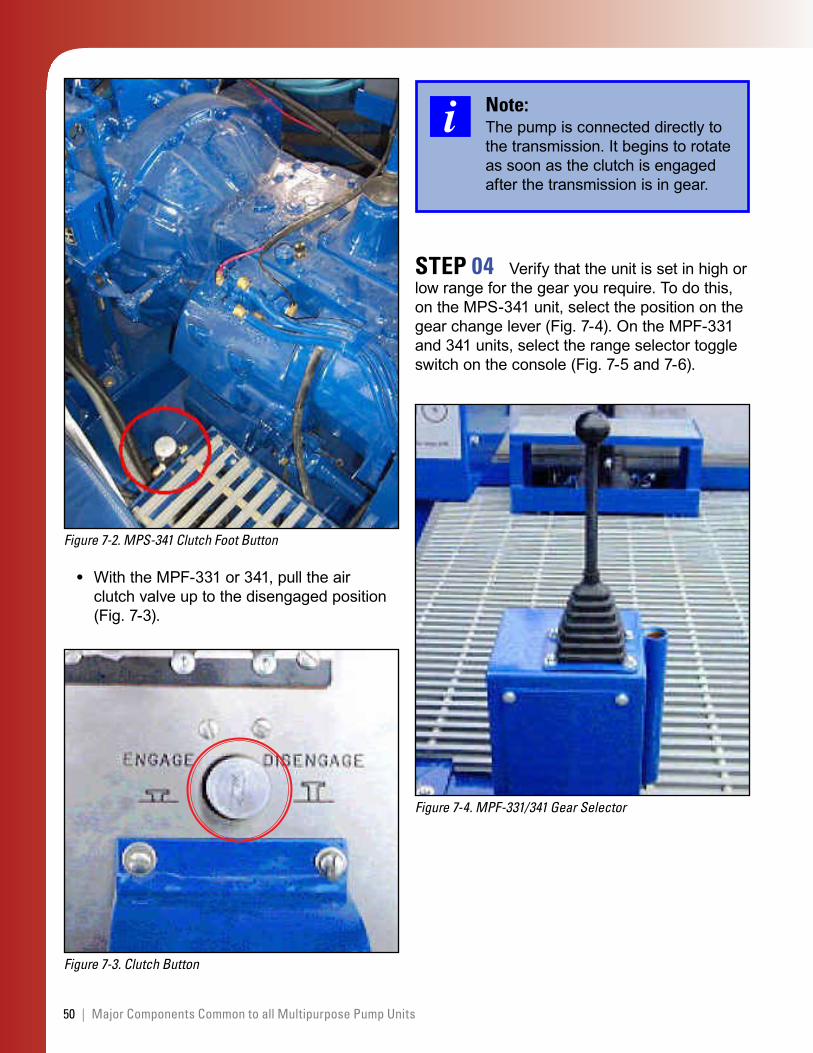
STEP 03 Disengage the clutch:
With the MPS-341, depress the clutch foot button (Fig. 7-2).
•
50 | Major Components Common to all Multipurpose Pump Units
Figure 7-2. MPS-341 Clutch Foot Button
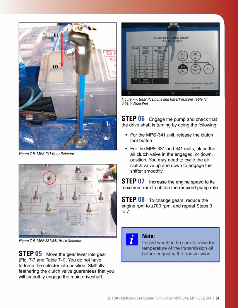
With the MPF-331 or 341, pull the air clutch valve up to the disengaged position (Fig. 7-3).
Figure 7-3. Clutch Button
•
Note:The pump is connected directly to the transmission. It begins to rotate as soon as the clutch is engaged after the transmission is in gear.
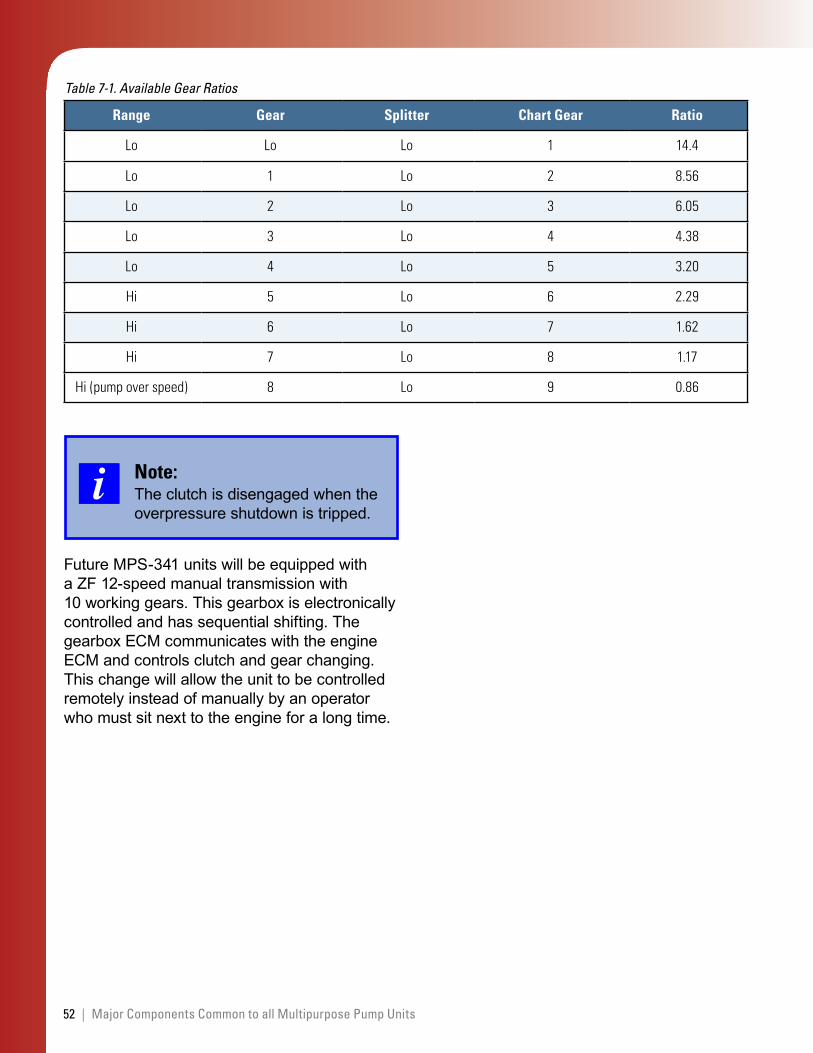
STEP 04 Verify that the unit is set in high or low range for the gear you require. To do this, on the MPS-341 unit, select the position on the gear change lever (Fig. 7-4). On the MPF-331 and 341 units, select the range selector toggle switch on the console (Fig. 7-5 and 7-6).
Figure 7-4. MPF-331/341 Gear Selector
51JET 30 - Multipurpose Single-Pump Units MPS-341, MPF-331, 341 |
Figure 7-5. MPS-341 Gear Selector
HI
LO
Figure 7-6. MPF-331/341 Hi-Lo Selector
STEP 05 Move the gear lever into gear (Fig. 7-7 and Table 7-1). You do not have to force the selector into position. Skillfully feathering the clutch valve guarantees that you will smoothly engage the main driveshaft.
Figure 7-7. Gear Positions and Rate/Pressure Table for 2.75-in Fluid End
STEP 06 Engage the pump and check that the drive shaft is turning by doing the following:
For the MPS-341 unit, release the clutch foot button.
For the MPF-331 and 341 units, place the air clutch valve in the engaged, or down, position. You may need to cycle the air clutch valve up and down to engage the shifter smoothly.
STEP 07 Increase the engine speed to its maximum rpm to obtain the required pump rate.
STEP 08 To change gears, reduce the engine rpm to ±700 rpm, and repeat Steps 3 to 7.
Note:In cold weather, be sure to raise the temperature of the transmission oil before engaging the transmission.
•
•
52 | Major Components Common to all Multipurpose Pump Units
Range Gear Splitter Chart Gear Ratio
Lo Lo Lo 1 14.4
Lo 1 Lo 2 8.56
Lo 2 Lo 3 6.05
Lo 3 Lo 4 4.38
Lo 4 Lo 5 3.20
Hi 5 Lo 6 2.29
Hi 6 Lo 7 1.62
Hi 7 Lo 8 1.17
Hi(pumpoverspeed) 8 Lo 9 0.86
Table 7-1. Available Gear Ratios
Note:The clutch is disengaged when the overpressure shutdown is tripped.
Future MPS-341 units will be equipped with a ZF 12-speed manual transmission with 10 working gears. This gearbox is electronically controlled and has sequential shifting. The gearbox ECM communicates with the engine ECM and controls clutch and gear changing. This change will allow the unit to be controlled remotely instead of manually by an operator who must sit next to the engine for a long time.
53JET 30 - Multipurpose Single-Pump Units MPS-341, MPF-331, 341 |
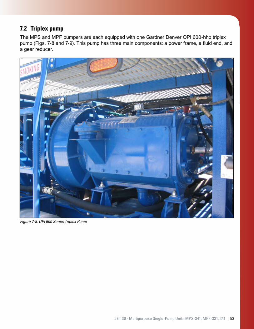
7.2 Triplex pumpThe MPS and MPF pumpers are each equipped with one Gardner Denver OPI 600-hhp triplex pump (Figs. 7-8 and 7-9). This pump has three main components: a power frame, a fluid end, and a gear reducer.
Figure 7-8. OPI 600 Series Triplex Pump
54 | Major Components Common to all Multipurpose Pump Units
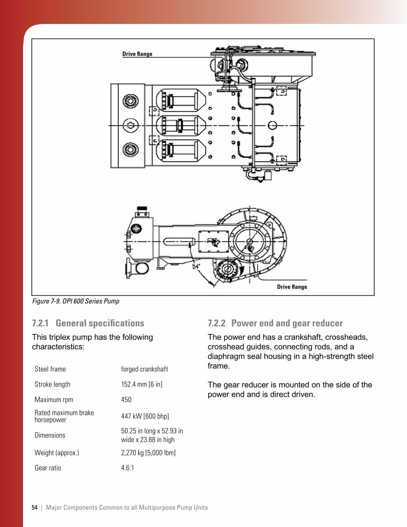
Figure 7-9. OPI 600 Series Pump
Drive flange
Drive flange
7.2.1 General specificationsThis triplex pump has the following characteristics:
Steelframe forgedcrankshaft
Strokelength 152.4mm[6in]
Maximumrpm 450
Ratedmaximumbrakehorsepower 447kW[600bhp]
Dimensions 50.25inlongx52.93inwidex23.88inhigh
Weight(approx.) 2,270kg[5,000lbm]
Gearratio 4.6:1
7.2.2 Power end and gear reducerThe power end has a crankshaft, crossheads, crosshead guides, connecting rods, and a diaphragm seal housing in a high-strength steel frame.
The gear reducer is mounted on the side of the power end and is direct driven.
55JET 30 - Multipurpose Single-Pump Units MPS-341, MPF-331, 341 |
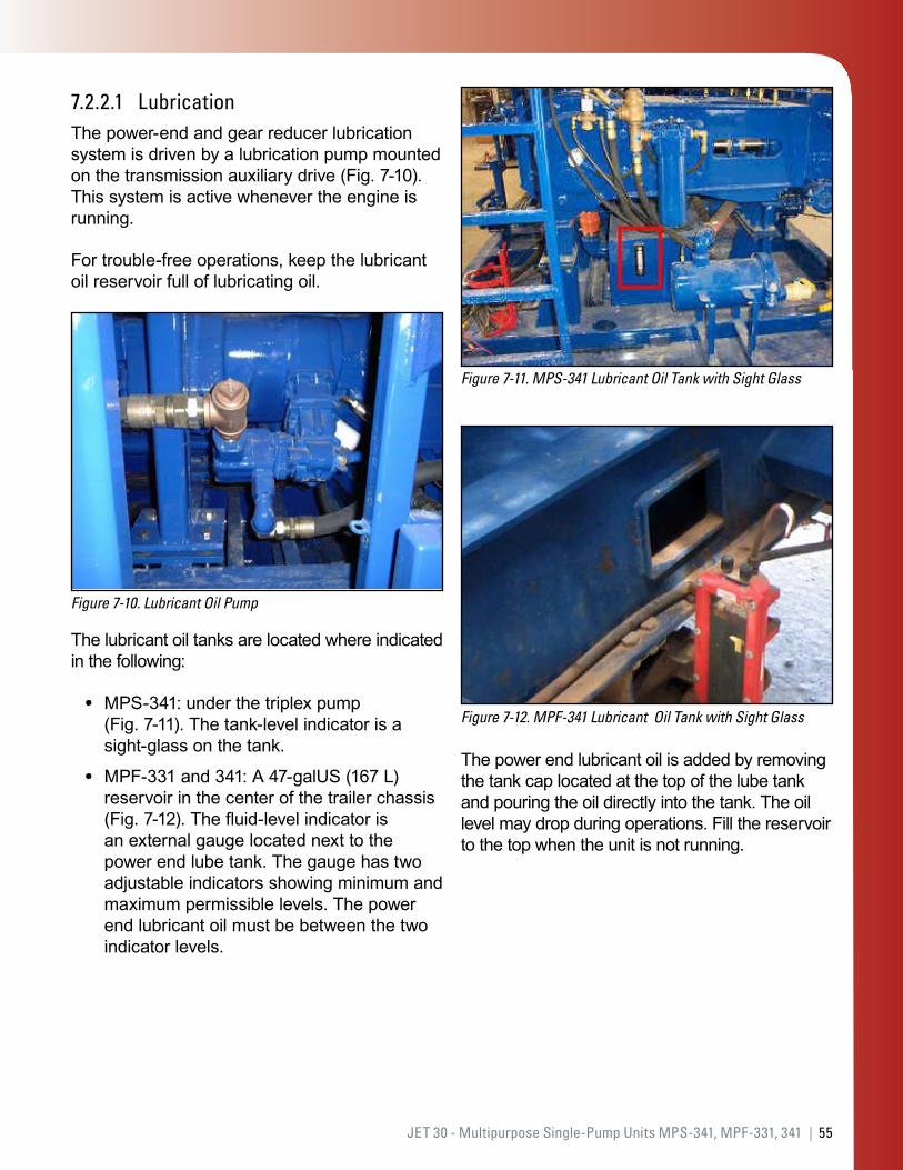
7.2.2.1 LubricationThe power-end and gear reducer lubrication system is driven by a lubrication pump mounted on the transmission auxiliary drive (Fig. 7-10). This system is active whenever the engine is running.
For trouble-free operations, keep the lubricant oil reservoir full of lubricating oil.
Figure 7-10. Lubricant Oil Pump
The lubricant oil tanks are located where indicated in the following:
MPS-341: under the triplex pump (Fig. 7-11). The tank-level indicator is a sight-glass on the tank.
MPF-331 and 341: A 47-galUS (167 L) reservoir in the center of the trailer chassis (Fig. 7-12). The fluid-level indicator is an external gauge located next to the power end lube tank. The gauge has two adjustable indicators showing minimum and maximum permissible levels. The power end lubricant oil must be between the two indicator levels.
•
•
Figure 7-11. MPS-341 Lubricant Oil Tank with Sight Glass
Figure 7-12. MPF-341 Lubricant Oil Tank with Sight Glass
The power end lubricant oil is added by removing the tank cap located at the top of the lube tank and pouring the oil directly into the tank. The oil level may drop during operations. Fill the reservoir to the top when the unit is not running.
56 | Major Components Common to all Multipurpose Pump Units
7.2.3 Fluid endsThe OPI Series 600 fluid end comes in two sizes. The standard size is 2.75 in.
The ratings that apply to the fluid ends are shown in Table 7-2.
Fluid end size (in)
Maximum pressure rating
(psi) [mPa]
ERAD pump K factor (mBBL per
pulse)
2.75 15,000[103] 0.29047
3.50(optional)
10,000[69] 0.4705
Table 7-2. Fluid End Ratings
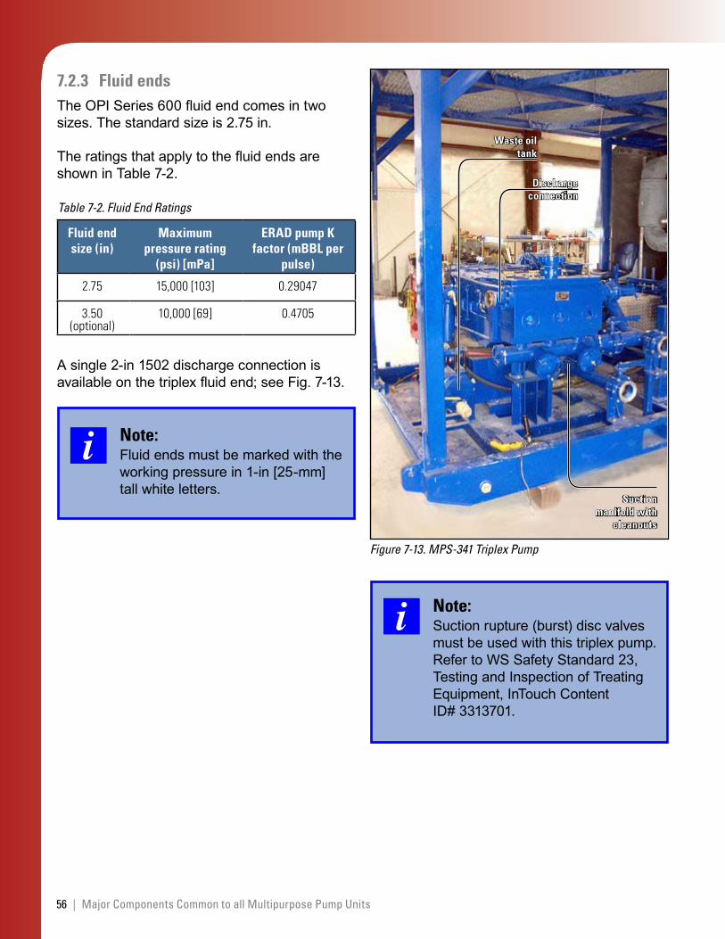
A single 2-in 1502 discharge connection is available on the triplex fluid end; see Fig. 7-13.
Note:Fluid ends must be marked with the working pressure in 1-in [25-mm] tall white letters.
Figure 7-13. MPS-341 Triplex Pump
Waste oil tank
Suction manifold with
cleanouts
Discharge connection
Note:Suction rupture (burst) disc valves must be used with this triplex pump. Refer to WS Safety Standard 23, Testing and Inspection of Treating Equipment, InTouch Content ID# 3313701.
57JET 30 - Multipurpose Single-Pump Units MPS-341, MPF-331, 341 |
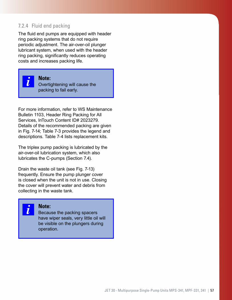
7.2.4 Fluid end packingThe fluid end pumps are equipped with header ring packing systems that do not require periodic adjustment. The air-over-oil plunger lubricant system, when used with the header ring packing, significantly reduces operating costs and increases packing life.
Note:Overtightening will cause the packing to fail early.
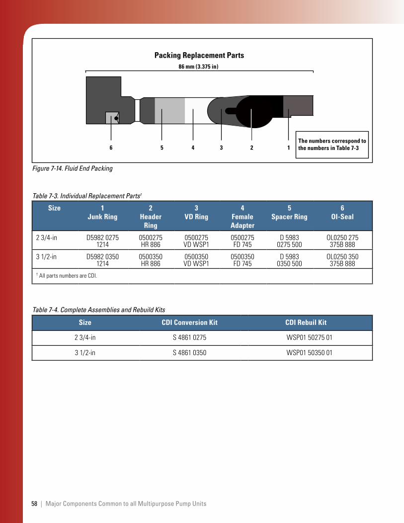
For more information, refer to WS Maintenance Bulletin 1103, Header Ring Packing for All Services, InTouch Content ID# 2023279. Details of the recommended packing are given in Fig. 7-14; Table 7-3 provides the legend and descriptions. Table 7-4 lists replacement kits.
The triplex pump packing is lubricated by the air-over-oil lubrication system, which also lubricates the C-pumps (Section 7.4).
Drain the waste oil tank (see Fig. 7-13) frequently. Ensure the pump plunger cover is closed when the unit is not in use. Closing the cover will prevent water and debris from collecting in the waste tank.
Note:Because the packing spacers have wiper seals, very little oil will be visible on the plungers during operation.
58 | Major Components Common to all Multipurpose Pump Units
Figure 7-14. Fluid End Packing
Packing Replacement Parts
6 5 4 3 2 1The numbers correspond to the numbers in Table 7-3
86 mm (3.375 in)
Size 1 Junk Ring
2 Header
Ring
3 VD Ring
4 Female Adapter
5 Spacer Ring
6 OI-Seal
23/4-in D598202751214
0500275HR886
0500275VDWSP1
0500275FD745
D59830275500
OL0250275375B888
31/2-in D598203501214
0500350HR886
0500350VDWSP1
0500350FD745
D59830350500
OL0250350375B888
†AllpartsnumbersareCDI.
Table 7-3. Individual Replacement Parts†
Size CDI Conversion Kit CDI Rebuil Kit
23/4-in S48610275 WSP015027501
31/2-in S48610350 WSP015035001
Table 7-4. Complete Assemblies and Rebuild Kits
59JET 30 - Multipurpose Single-Pump Units MPS-341, MPF-331, 341 |
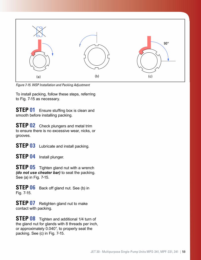
Figure 7-15. WSP Installation and Packing Adjustment
90°
(a) (b) (c)
To install packing, follow these steps, referring to Fig. 7-15 as necessary.
STEP 01 Ensure stuffing box is clean and smooth before installing packing.
STEP 02 Check plungers and metal trim to ensure there is no excessive wear, nicks, or grooves.
STEP 03 Lubricate and install packing.
STEP 04 Install plunger.
STEP 05 Tighten gland nut with a wrench (do not use cheater bar) to seat the packing. See (a) in Fig. 7-15.
STEP 06 Back off gland nut. See (b) in Fig. 7-15.
STEP 07 Retighten gland nut to make contact with packing.
STEP 08 Tighten and additional 1/4 turn of the gland nut for glands with 8 threads per inch, or approximately 0.040°, to properly seat the packing. See (c) in Fig. 7-15.
60 | Major Components Common to all Multipurpose Pump Units
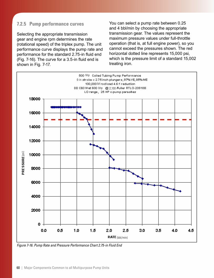
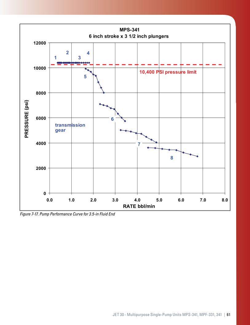
7.2.5 Pump performance curves
Selecting the appropriate transmission gear and engine rpm determines the rate (rotational speed) of the triplex pump. The unit performance curve displays the pump rate and performance for the standard 2.75-in fluid end (Fig. 7-16). The curve for a 3.5-in fluid end is shown in Fig. 7-17.
Figure 7-16. Pump Rate and Pressure Performance Chart 2.75-in Fluid End
hhp
bhp 2,100
(bbl/min)
(psi
)
6-inlbf
You can select a pump rate between 0.25 and 4 bbl/min by choosing the appropriate transmission gear. The values represent the maximum pressure values under full-throttle operation (that is, at full engine power), so you cannot exceed the pressures shown. The red horizontal dotted line represents 15,000 psi, which is the pressure limit of a standard 15,002 treating iron.
61JET 30 - Multipurpose Single-Pump Units MPS-341, MPF-331, 341 |
Figure 7-17. Pump Performance Curve for 3.5-in Fluid End
-341
bbl/min
(psi
)
62 | Major Components Common to all Multipurpose Pump Units
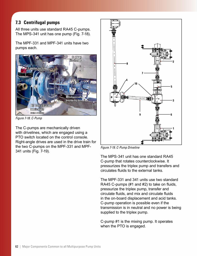
7.3 Centrifugal pumpsAll three units use standard RA45 C-pumps. The MPS-341 unit has one pump (Fig. 7-18).
The MPF-331 and MPF-341 units have two pumps each.
Figure 7-18. C-Pump
C-pump suction
C-pump discharge
Mechanically driven by driveline
Air over oil seal lubrication connection
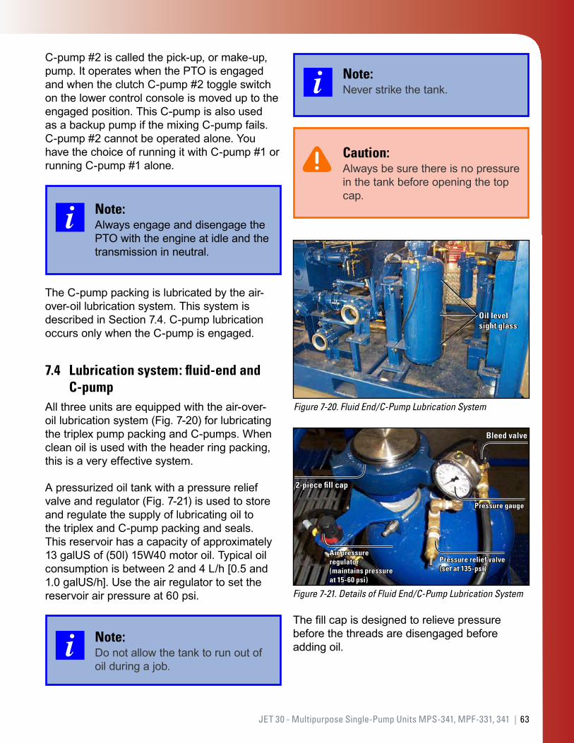
The C-pumps are mechanically driven with drivelines, which are engaged using a PTO switch located on the control console. Right-angle drives are used in the drive train for the two C-pumps on the MPF-331 and MPF-341 units (Fig. 7-19).
Figure 7-19. C-Pump Driveline
8
7
2
5
3
6
1
10
9
4
The MPS-341 unit has one standard RA45 C-pump that rotates counterclockwise. It pressurizes the triplex pump and transfers and circulates fluids to the external tanks.
The MPF-331 and 341 units use two standard RA45 C-pumps (#1 and #2) to take on fluids, pressurize the triplex pump, transfer and circulate fluids, and mix and circulate fluids in the on-board displacement and acid tanks. C-pump operation is possible even if the transmission is in neutral and no power is being supplied to the triplex pump.
C-pump #1 is the mixing pump. It operates when the PTO is engaged.
63JET 30 - Multipurpose Single-Pump Units MPS-341, MPF-331, 341 |
C-pump #2 is called the pick-up, or make-up, pump. It operates when the PTO is engaged and when the clutch C-pump #2 toggle switch on the lower control console is moved up to the engaged position. This C-pump is also used as a backup pump if the mixing C-pump fails. C-pump #2 cannot be operated alone. You have the choice of running it with C-pump #1 or running C-pump #1 alone.
Note:Always engage and disengage the PTO with the engine at idle and the transmission in neutral.
The C-pump packing is lubricated by the air-over-oil lubrication system. This system is described in Section 7.4. C-pump lubrication occurs only when the C-pump is engaged.
7.4 Lubrication system: fluid-end and C-pump
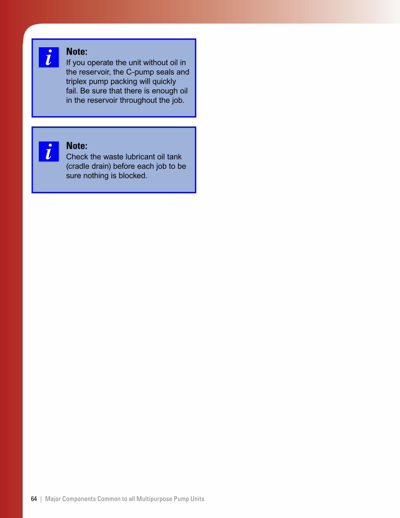
All three units are equipped with the air-over-oil lubrication system (Fig. 7-20) for lubricating the triplex pump packing and C-pumps. When clean oil is used with the header ring packing, this is a very effective system.
A pressurized oil tank with a pressure relief valve and regulator (Fig. 7-21) is used to store and regulate the supply of lubricating oil to the triplex and C-pump packing and seals. This reservoir has a capacity of approximately 13 galUS of (50l) 15W40 motor oil. Typical oil consumption is between 2 and 4 L/h [0.5 and 1.0 galUS/h]. Use the air regulator to set the reservoir air pressure at 60 psi.
Note:Do not allow the tank to run out of oil during a job.
Note:Never strike the tank.
Caution:Always be sure there is no pressure in the tank before opening the top cap.
Figure 7-20. Fluid End/C-Pump Lubrication System
Oil level sight glass
Figure 7-21. Details of Fluid End/C-Pump Lubrication System
Air pressure regulator (maintains pressure at 15-60 psi)
2-piece fill cap
Pressure relief valve (set at 135-psi)
Bleed valve
Pressure gauge
The fill cap is designed to relieve pressure before the threads are disengaged before adding oil.
64 | Major Components Common to all Multipurpose Pump Units
Note:If you operate the unit without oil in the reservoir, the C-pump seals and triplex pump packing will quickly fail. Be sure that there is enough oil in the reservoir throughout the job.
Note:Check the waste lubricant oil tank (cradle drain) before each job to be sure nothing is blocked.
65JET 30 - Multipurpose Single-Pump Units MPS-341, MPF-331, 341 |
8.0 UnitInspections
Several reports are listed below that will help you complete and document the inspections. The required maintenance and safety checks and paperwork are shown in Appendix A and are available in InTouch.
Driver’s Trip Report DS-598-2-A
Auxiliary Equipment Check Sheet DS-587-E
Truck Chassis Check Sheet DS-587-E 7-2
STEM I and STEM II checklists (InTouch Content ID# 4248056)
8.1 Inspections before leaving the district
You must make the following inspections before you leave the district:
Perform a STEM 1 inspection before the trailer leaves the district.
Follow the Schlumberger 15-point check list, as applicable, for the tractor and trailer, OFS QHSE S001: Journey Management and Driving, InTouch Content ID# 3051691.
Follow the four-point brake checklist also found in OFS QHSE S001.
If you add fuel before you leave the district, refer to Safety Standard 30: Pumping Combustible and Flammable Fluids, InTouch Content ID# 3313709.
Review any deficiencies recorded on the unit from the previous job.
Review all appropriate material safety data sheets (MSDSs), and place them in the tractor cab.
•
•
•
•
•
•
•
•
•
•
Properly store or tie down all loose equipment.
Ensure that a first aid kit is available.
Check the capacity and inspection dates of the fire extinguisher.
Check the eye wash bottle. If the level is low, fill it. If it looks unsafe (cloudy or dirty), clean and refill it.
Make sure the unit is clean and painted according to Schlumberger standards.
8.2 Prejob and postjob inspections (STEM 1)
The pump units and tractors that are used to take a unit to location must be inspected according to STEM 1 requirements. These inspections are done to ensure that the equipment is totally functional and to identify and repair any defective components.
Note:Always remember to keep the unit clean and painted and to have an up-to-date, documented maintenance record.
To maintain high service-quality standards, be sure to regularly inspect and proactively maintain engines, transmissions, triplex and C-pumps and their drive chains, process piping and valves, and air, hydraulic, and electrical systems.
•
•
•
•
•
66 | Unit Inspections
Note:You must follow lockout/tagout procedures when you work on equipment.
Do the following checks, where applicable, before you operate the equipment.
STEP 01 Check previous STEM I reports.
Read the most recent two or three STEM I reports. Ensure that all the items noted in those reports have been corrected. Ask these questions:
Is the equipment red or green tagged?
Have problems previously noted been corrected?
Are there recurring problems?
STEP 02 Check the engine oil.
Use SAE15W40 engine oil.
Check the level and condition of the oil in the unit and tractor engines. Add oil as required.
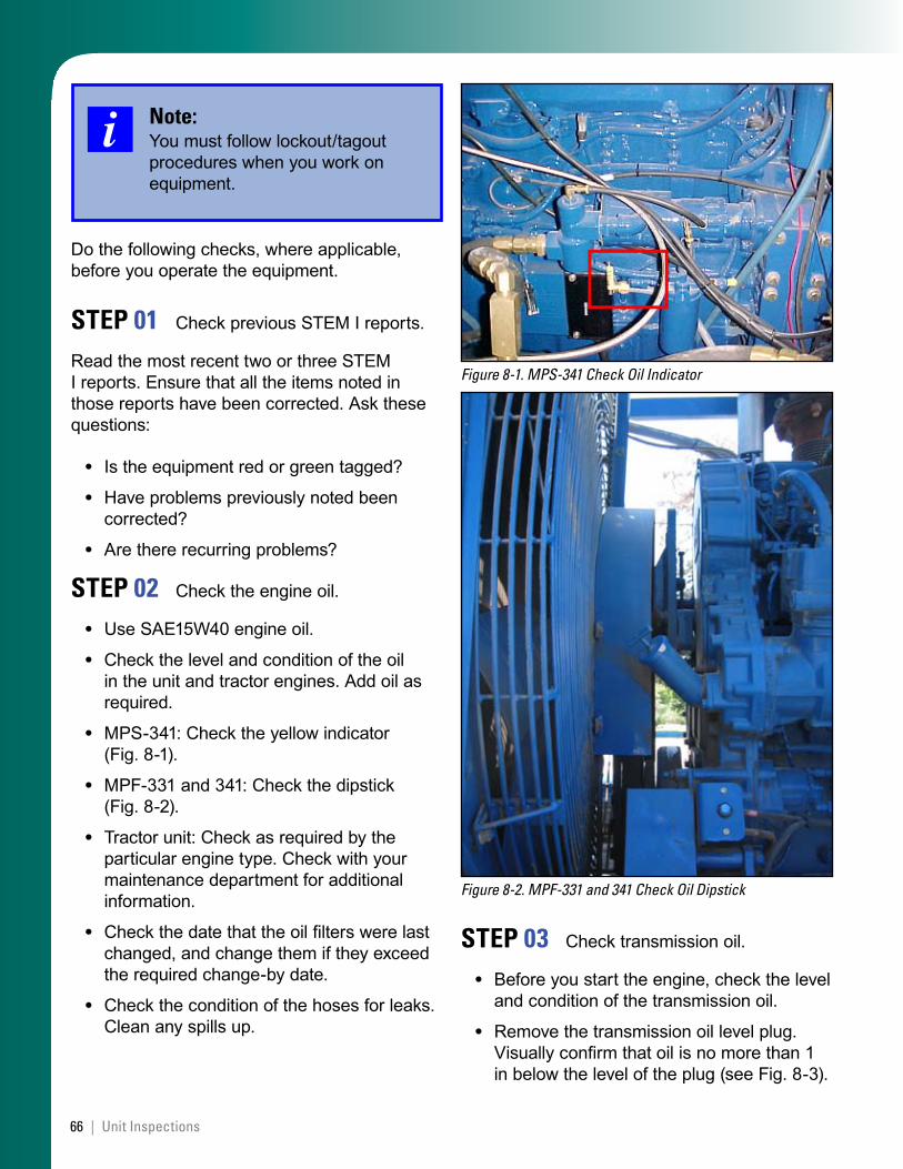
MPS-341: Check the yellow indicator (Fig. 8-1).
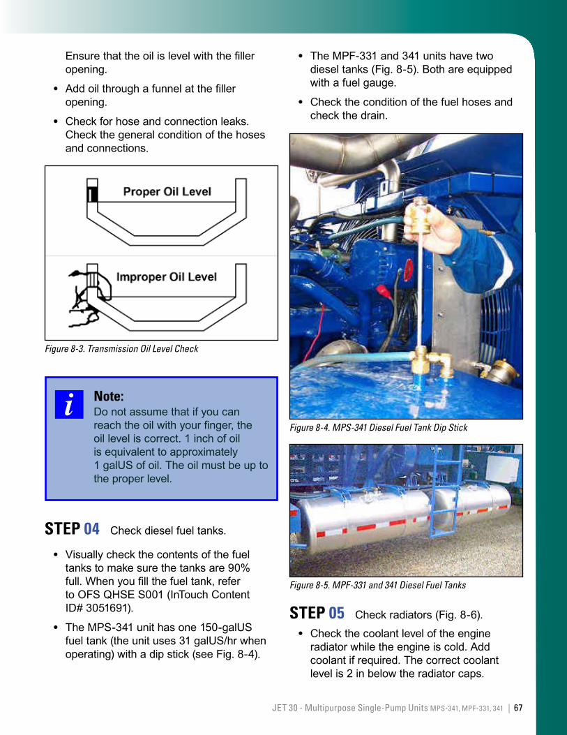
MPF-331 and 341: Check the dipstick (Fig. 8-2).
Tractor unit: Check as required by the particular engine type. Check with your maintenance department for additional information.
Check the date that the oil filters were last changed, and change them if they exceed the required change-by date.
Check the condition of the hoses for leaks. Clean any spills up.
•
•
•
•
•
•
•
•
•
•
Figure 8-1. MPS-341 Check Oil Indicator
Figure 8-2. MPF-331 and 341 Check Oil Dipstick
STEP 03 Check transmission oil.
Before you start the engine, check the level and condition of the transmission oil.
Remove the transmission oil level plug. Visually confirm that oil is no more than 1 in below the level of the plug (see Fig. 8-3).
•
•
67JET 30 - Multipurpose Single-Pump Units MPS-341, MPF-331, 341 |
Ensure that the oil is level with the filler opening.
Add oil through a funnel at the filler opening.
Check for hose and connection leaks. Check the general condition of the hoses and connections.
Figure 8-3. Transmission Oil Level Check
Note:Do not assume that if you can reach the oil with your finger, the oil level is correct. 1 inch of oil is equivalent to approximately 1 galUS of oil. The oil must be up to the proper level.
STEP 04 Check diesel fuel tanks.
Visually check the contents of the fuel tanks to make sure the tanks are 90% full. When you fill the fuel tank, refer to OFS QHSE S001 (InTouch Content ID# 3051691).
The MPS-341 unit has one 150-galUS fuel tank (the unit uses 31 galUS/hr when operating) with a dip stick (see Fig. 8-4).
•
•
•
•
The MPF-331 and 341 units have two diesel tanks (Fig. 8-5). Both are equipped with a fuel gauge.
Check the condition of the fuel hoses and check the drain.
Figure 8-4. MPS-341 Diesel Fuel Tank Dip Stick
Figure 8-5. MPF-331 and 341 Diesel Fuel Tanks
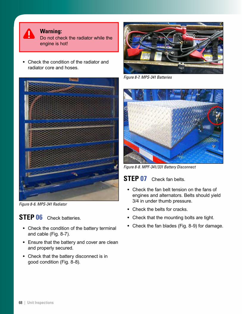
STEP 05 Check radiators (Fig. 8-6).
Check the coolant level of the engine radiator while the engine is cold. Add coolant if required. The correct coolant level is 2 in below the radiator caps.
•
•
•
68 | Unit Inspections
Warning:Do not check the radiator while the engine is hot!
Check the condition of the radiator and radiator core and hoses.
Figure 8-6. MPS-341 Radiator
STEP 06 Check batteries.
Check the condition of the battery terminal and cable (Fig. 8-7).
Ensure that the battery and cover are clean and properly secured.
Check that the battery disconnect is in good condition (Fig. 8-8).
•
•
•
•
Figure 8-7. MPS-341 Batteries
Figure 8-8. MPF-341/331 Battery Disconnect
STEP 07 Check fan belts.
Check the fan belt tension on the fans of engines and alternators. Belts should yield 3/4 in under thumb pressure.
Check the belts for cracks.
Check that the mounting bolts are tight.
Check the fan blades (Fig. 8-9) for damage.
•
•
•
•
69JET 30 - Multipurpose Single-Pump Units MPS-341, MPF-331, 341 |
Figure 8-9. Radiator Fan Belts
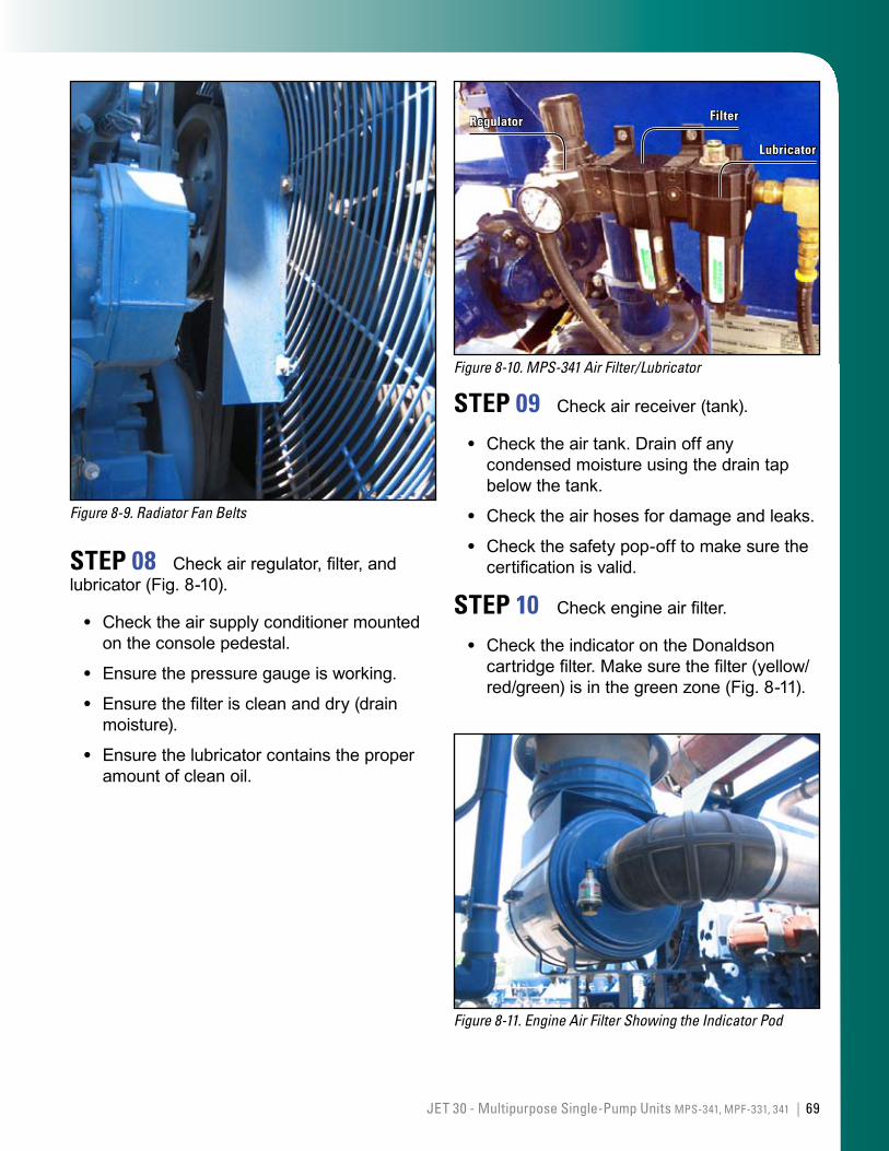
STEP 08 Check air regulator, filter, and lubricator (Fig. 8-10).
Check the air supply conditioner mounted on the console pedestal.
Ensure the pressure gauge is working.
Ensure the filter is clean and dry (drain moisture).
Ensure the lubricator contains the proper amount of clean oil.
•
•
•
•
Figure 8-10. MPS-341 Air Filter/Lubricator
Lubricator
FilterRegulator
STEP 09 Check air receiver (tank).
Check the air tank. Drain off any condensed moisture using the drain tap below the tank.
Check the air hoses for damage and leaks.
Check the safety pop-off to make sure the certification is valid.
STEP 10 Check engine air filter.
Check the indicator on the Donaldson cartridge filter. Make sure the filter (yellow/red/green) is in the green zone (Fig. 8-11).
Figure 8-11. Engine Air Filter Showing the Indicator Pod
•
•
•
•
70 | Unit Inspections
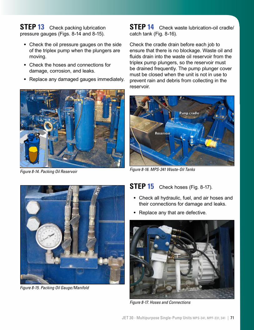
STEP 11 Check power-end/gear reducer oil.
Use SAE 90 gear oil.
Check the level and condition of the oil that lubricates the power-ends, gear reducers, and right-angle drives of the C-pumps.
Check the oil tank level:
MPS-341 unit: Use the sight glass on the tank below the triplex pump (Fig. 8-12). The indicator should read “Full” when the pumps are not working. The level will decrease when the unit is operational.
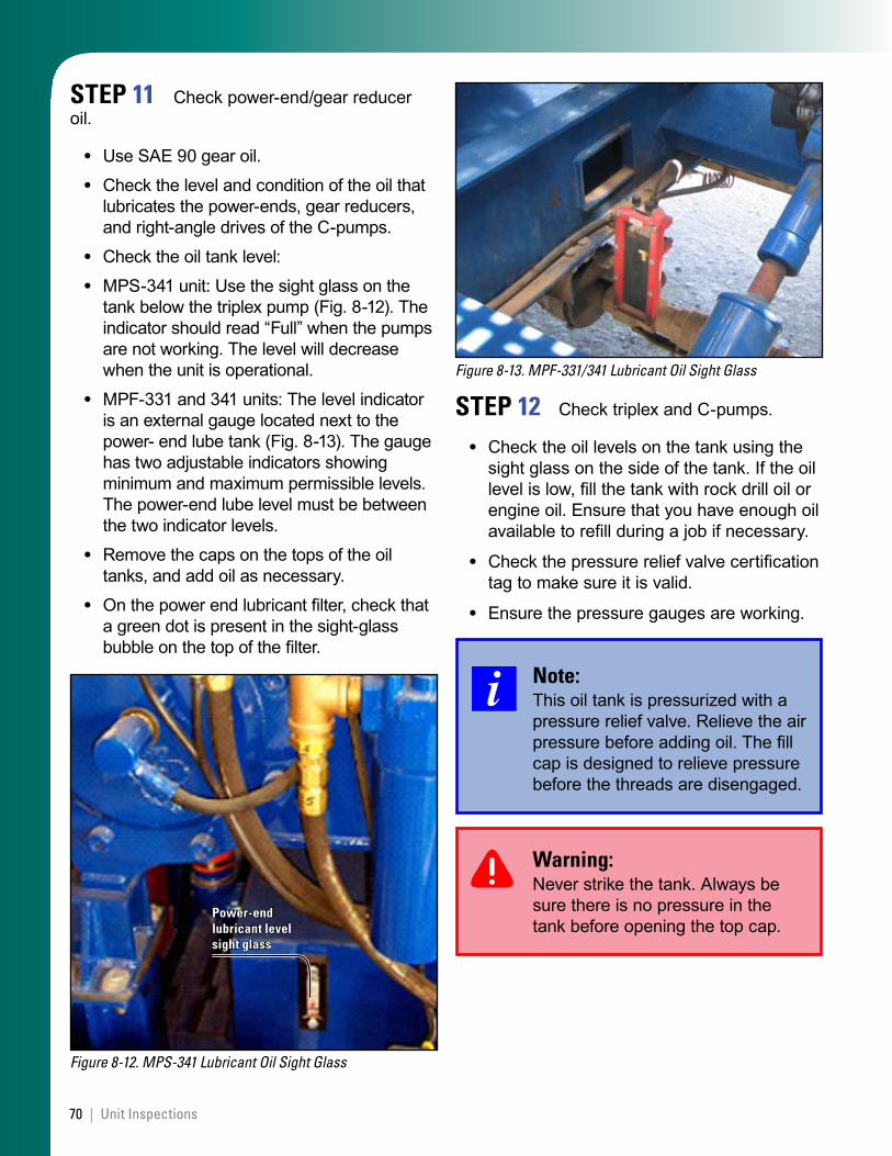
MPF-331 and 341 units: The level indicator is an external gauge located next to the power- end lube tank (Fig. 8-13). The gauge has two adjustable indicators showing minimum and maximum permissible levels. The power-end lube level must be between the two indicator levels.
Remove the caps on the tops of the oil tanks, and add oil as necessary.
On the power end lubricant filter, check that a green dot is present in the sight-glass bubble on the top of the filter.
Figure 8-12. MPS-341 Lubricant Oil Sight Glass
Power-end lubricant level sight glass
••
••
•
•
•
Figure 8-13. MPF-331/341 Lubricant Oil Sight Glass
STEP 12 Check triplex and C-pumps.
Check the oil levels on the tank using the sight glass on the side of the tank. If the oil level is low, fill the tank with rock drill oil or engine oil. Ensure that you have enough oil available to refill during a job if necessary.
Check the pressure relief valve certification tag to make sure it is valid.
Ensure the pressure gauges are working.
Note:This oil tank is pressurized with a pressure relief valve. Relieve the air pressure before adding oil. The fill cap is designed to relieve pressure before the threads are disengaged.
Warning:Never strike the tank. Always be sure there is no pressure in the tank before opening the top cap.
•
•
•
71JET 30 - Multipurpose Single-Pump Units MPS-341, MPF-331, 341 |
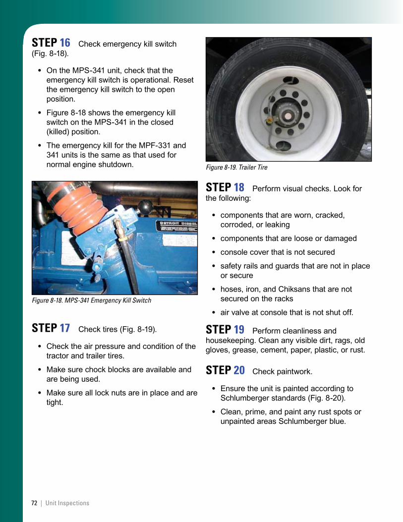
STEP 13 Check packing lubrication pressure gauges (Figs. 8-14 and 8-15).
Check the oil pressure gauges on the side of the triplex pump when the plungers are moving.
Check the hoses and connections for damage, corrosion, and leaks.
Replace any damaged gauges immediately.
Figure 8-14. Packing Oil Reservoir
Figure 8-15. Packing Oil Gauge/Manifold
•
•
•
STEP 14 Check waste lubrication-oil cradle/catch tank (Fig. 8-16).
Check the cradle drain before each job to ensure that there is no blockage. Waste oil and fluids drain into the waste oil reservoir from the triplex pump plungers, so the reservoir must be drained frequently. The pump plunger cover must be closed when the unit is not in use to prevent rain and debris from collecting in the reservoir.
Figure 8-16. MPS-341 Waste-Oil Tanks
Reservoir
Pump cradle
STEP 15 Check hoses (Fig. 8-17).
Check all hydraulic, fuel, and air hoses and their connections for damage and leaks.
Replace any that are defective.
Figure 8-17. Hoses and Connections
•
•
72 | Unit Inspections
STEP 16 Check emergency kill switch (Fig. 8-18).
On the MPS-341 unit, check that the emergency kill switch is operational. Reset the emergency kill switch to the open position.
Figure 8-18 shows the emergency kill switch on the MPS-341 in the closed (killed) position.
The emergency kill for the MPF-331 and 341 units is the same as that used for normal engine shutdown.
Figure 8-18. MPS-341 Emergency Kill Switch
STEP 17 Check tires (Fig. 8-19).
Check the air pressure and condition of the tractor and trailer tires.
Make sure chock blocks are available and are being used.
Make sure all lock nuts are in place and are tight.
•
•
•
•
•
•
Figure 8-19. Trailer Tire
STEP 18 Perform visual checks. Look for the following:
components that are worn, cracked, corroded, or leaking
components that are loose or damaged
console cover that is not secured
safety rails and guards that are not in place or secure
hoses, iron, and Chiksans that are not secured on the racks
air valve at console that is not shut off.
STEP 19 Perform cleanliness and housekeeping. Clean any visible dirt, rags, old gloves, grease, cement, paper, plastic, or rust.
STEP 20 Check paintwork.
Ensure the unit is painted according to Schlumberger standards (Fig. 8-20).
Clean, prime, and paint any rust spots or unpainted areas Schlumberger blue.
•
•
•
•
•
•
•
•
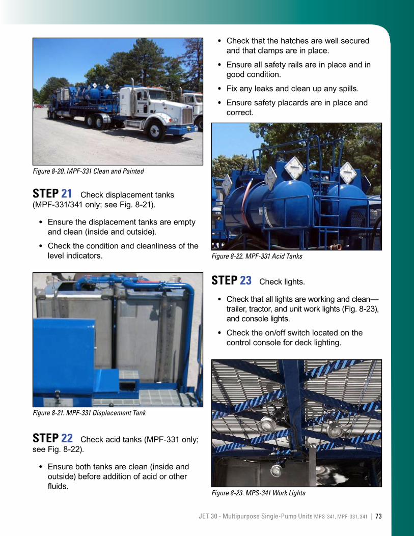
73JET 30 - Multipurpose Single-Pump Units MPS-341, MPF-331, 341 |
Figure 8-20. MPF-331 Clean and Painted
STEP 21 Check displacement tanks (MPF-331/341 only; see Fig. 8-21).
Ensure the displacement tanks are empty and clean (inside and outside).
Check the condition and cleanliness of the level indicators.
Figure 8-21. MPF-331 Displacement Tank
STEP 22 Check acid tanks (MPF-331 only; see Fig. 8-22).
Ensure both tanks are clean (inside and outside) before addition of acid or other fluids.
•
•
•
Check that the hatches are well secured and that clamps are in place.
Ensure all safety rails are in place and in good condition.
Fix any leaks and clean up any spills.
Ensure safety placards are in place and correct.
Figure 8-22. MPF-331 Acid Tanks
STEP 23 Check lights.
Check that all lights are working and clean—trailer, tractor, and unit work lights (Fig. 8-23), and console lights.
Check the on/off switch located on the control console for deck lighting.
Figure 8-23. MPS-341 Work Lights
•
•
•
•
•
•
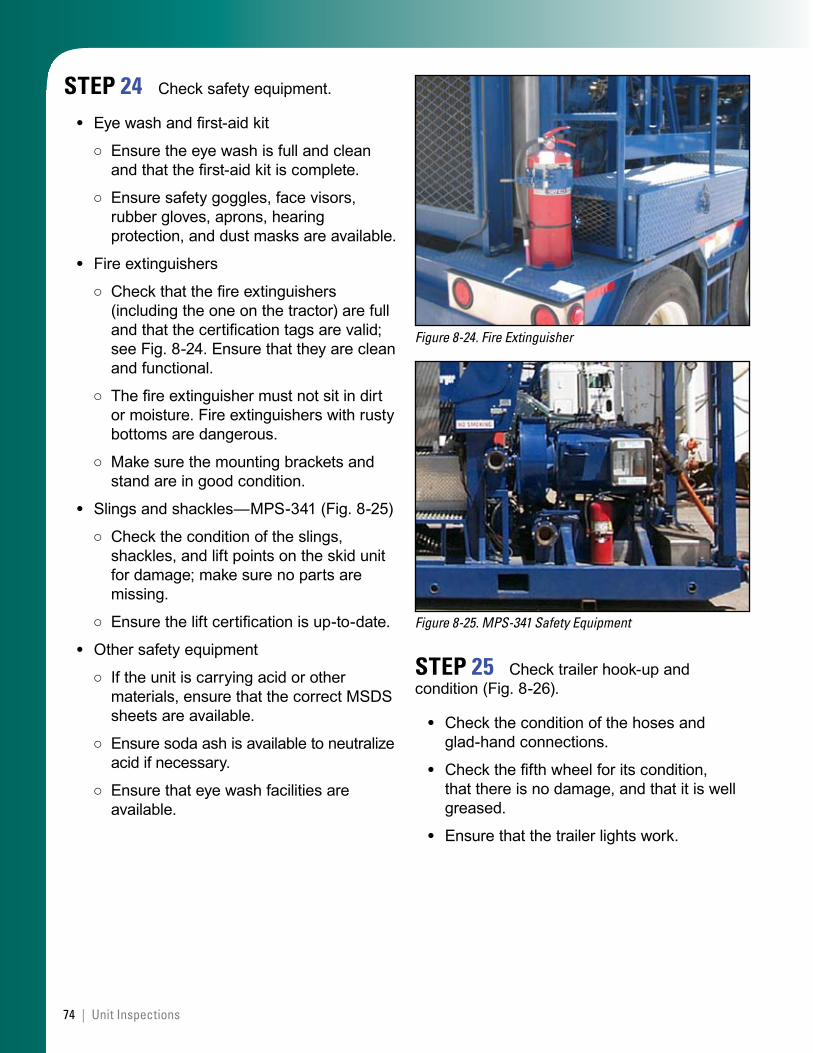
74 | Unit Inspections
STEP 24 Check safety equipment.
Eye wash and first-aid kit
Ensure the eye wash is full and clean and that the first-aid kit is complete.
Ensure safety goggles, face visors, rubber gloves, aprons, hearing protection, and dust masks are available.
Fire extinguishers
Check that the fire extinguishers (including the one on the tractor) are full and that the certification tags are valid; see Fig. 8-24. Ensure that they are clean and functional.
The fire extinguisher must not sit in dirt or moisture. Fire extinguishers with rusty bottoms are dangerous.
Make sure the mounting brackets and stand are in good condition.
Slings and shackles—MPS-341 (Fig. 8-25)
Check the condition of the slings, shackles, and lift points on the skid unit for damage; make sure no parts are missing.
Ensure the lift certification is up-to-date.
Other safety equipment
If the unit is carrying acid or other materials, ensure that the correct MSDS sheets are available.
Ensure soda ash is available to neutralize acid if necessary.
Ensure that eye wash facilities are available.
•
○
○
•
○
○
○
•
○
○
•
○
○
○
Figure 8-24. Fire Extinguisher
Figure 8-25. MPS-341 Safety Equipment
STEP 25 Check trailer hook-up and condition (Fig. 8-26).
Check the condition of the hoses and glad-hand connections.
Check the fifth wheel for its condition, that there is no damage, and that it is well greased.
Ensure that the trailer lights work.
•
•
•
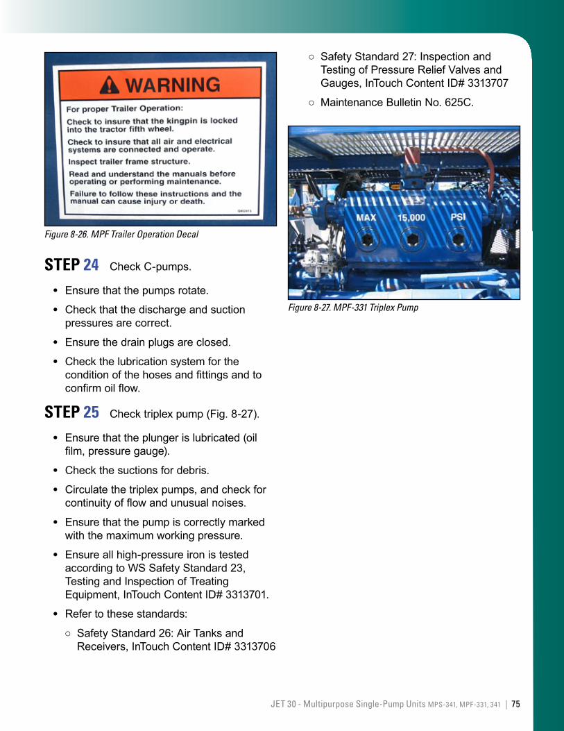
75JET 30 - Multipurpose Single-Pump Units MPS-341, MPF-331, 341 |
Figure 8-26. MPF Trailer Operation Decal
STEP 24 Check C-pumps.
Ensure that the pumps rotate.
Check that the discharge and suction pressures are correct.
Ensure the drain plugs are closed.
Check the lubrication system for the condition of the hoses and fittings and to confirm oil flow.
STEP 25 Check triplex pump (Fig. 8-27).
Ensure that the plunger is lubricated (oil film, pressure gauge).
Check the suctions for debris.
Circulate the triplex pumps, and check for continuity of flow and unusual noises.
Ensure that the pump is correctly marked with the maximum working pressure.
Ensure all high-pressure iron is tested according to WS Safety Standard 23, Testing and Inspection of Treating Equipment, InTouch Content ID# 3313701.
Refer to these standards:
Safety Standard 26: Air Tanks and Receivers, InTouch Content ID# 3313706
•
•
•
•
•
•
•
•
•
•
○
Safety Standard 27: Inspection and Testing of Pressure Relief Valves and Gauges, InTouch Content ID# 3313707
Maintenance Bulletin No. 625C.
Figure 8-27. MPF-331 Triplex Pump
○
○

76 | Unit Inspections
This page left intentionally blank
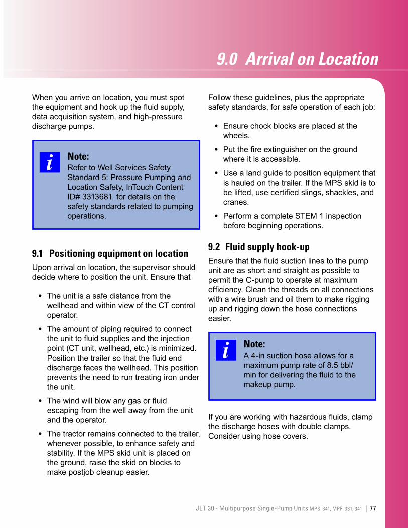
77JET 30 - Multipurpose Single-Pump Units MPS-341, MPF-331, 341 |
9.0 ArrivalonLocation
When you arrive on location, you must spot the equipment and hook up the fluid supply, data acquisition system, and high-pressure discharge pumps.
Note:Refer to Well Services Safety Standard 5: Pressure Pumping and Location Safety, InTouch Content ID# 3313681, for details on the safety standards related to pumping operations.
9.1 Positioning equipment on locationUpon arrival on location, the supervisor should decide where to position the unit. Ensure that
The unit is a safe distance from the wellhead and within view of the CT control operator.
The amount of piping required to connect the unit to fluid supplies and the injection point (CT unit, wellhead, etc.) is minimized. Position the trailer so that the fluid end discharge faces the wellhead. This position prevents the need to run treating iron under the unit.
The wind will blow any gas or fluid escaping from the well away from the unit and the operator.
The tractor remains connected to the trailer, whenever possible, to enhance safety and stability. If the MPS skid unit is placed on the ground, raise the skid on blocks to make postjob cleanup easier.
•
•
•
•
Follow these guidelines, plus the appropriate safety standards, for safe operation of each job:
Ensure chock blocks are placed at the wheels.
Put the fire extinguisher on the ground where it is accessible.
Use a land guide to position equipment that is hauled on the trailer. If the MPS skid is to be lifted, use certified slings, shackles, and cranes.
Perform a complete STEM 1 inspection before beginning operations.
9.2 Fluid supply hook-upEnsure that the fluid suction lines to the pump unit are as short and straight as possible to permit the C-pump to operate at maximum efficiency. Clean the threads on all connections with a wire brush and oil them to make rigging up and rigging down the hose connections easier.
Note:A 4-in suction hose allows for a maximum pump rate of 8.5 bbl/min for delivering the fluid to the makeup pump.
If you are working with hazardous fluids, clamp the discharge hoses with double clamps. Consider using hose covers.
•
•
•
•
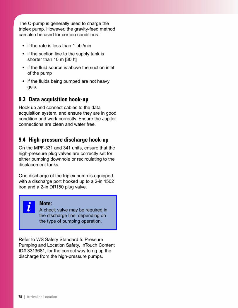
78 | Arrival on Location
The C-pump is generally used to charge the triplex pump. However, the gravity-feed method can also be used for certain conditions:
if the rate is less than 1 bbl/min
if the suction line to the supply tank is shorter than 10 m [30 ft]
if the fluid source is above the suction inlet of the pump
if the fluids being pumped are not heavy gels.
9.3 Data acquisition hook-upHook up and connect cables to the data acquisition system, and ensure they are in good condition and work correctly. Ensure the Jupiter connections are clean and water free.
9.4 High-pressure discharge hook-up On the MPF-331 and 341 units, ensure that the high-pressure plug valves are correctly set for either pumping downhole or recirculating to the displacement tanks.
One discharge of the triplex pump is equipped with a discharge port hooked up to a 2-in 1502 iron and a 2-in DR150 plug valve.
Note:A check valve may be required in the discharge line, depending on the type of pumping operation.
Refer to WS Safety Standard 5: Pressure Pumping and Location Safety, InTouch Content ID# 3313681, for the correct way to rig up the discharge from the high-pressure pumps.
•
•
•
•
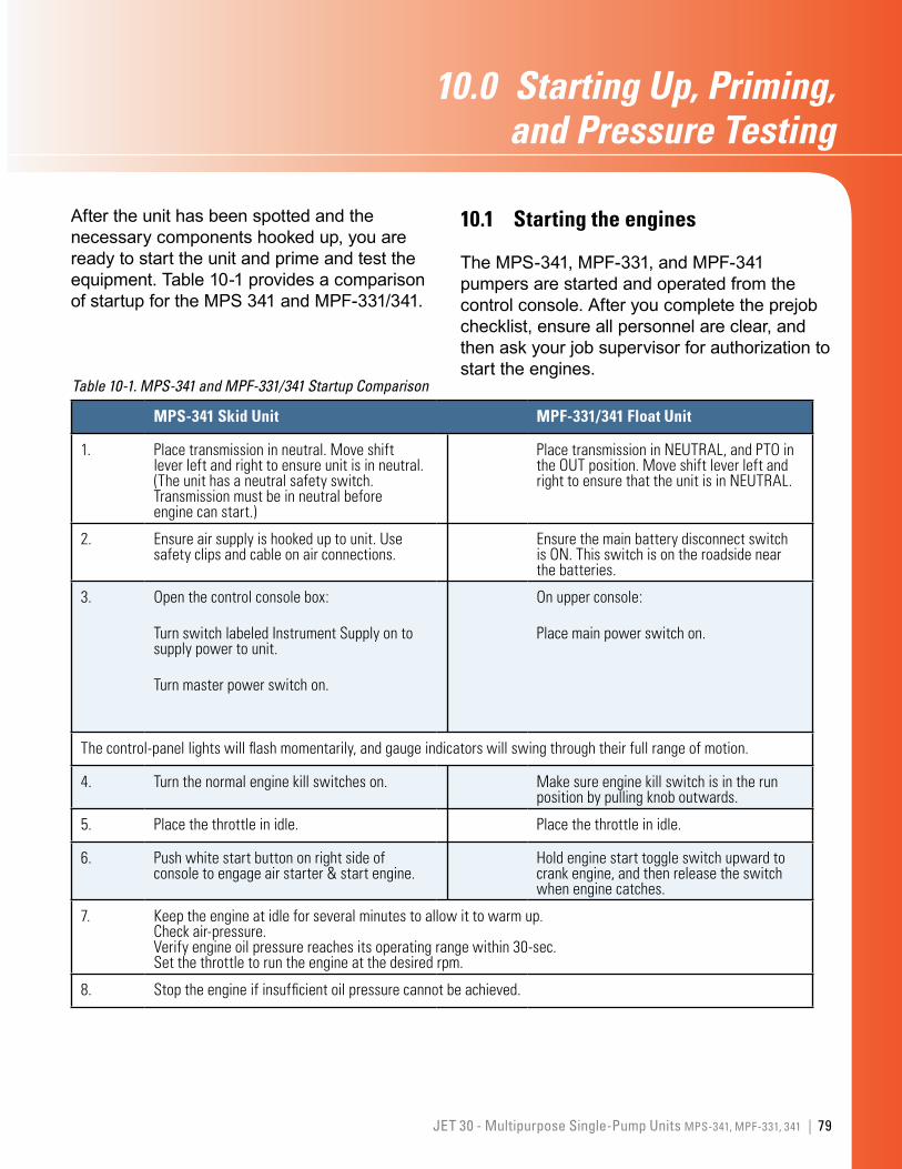
79JET 30 - Multipurpose Single-Pump Units MPS-341, MPF-331, 341 |
10.0 StartingUp,Priming,andPressureTesting
After the unit has been spotted and the necessary components hooked up, you are ready to start the unit and prime and test the equipment. Table 10-1 provides a comparison of startup for the MPS 341 and MPF-331/341.
MPS-341 Skid Unit MPF-331/341 Float Unit
1. Placetransmissioninneutral.Moveshiftleverleftandrighttoensureunitisinneutral.(Theunithasaneutralsafetyswitch.Transmissionmustbeinneutralbeforeenginecanstart.)
PlacetransmissioninNEUTRAL,andPTOintheOUTposition.MoveshiftleverleftandrighttoensurethattheunitisinNEUTRAL.
2. Ensureairsupplyishookeduptounit.Usesafetyclipsandcableonairconnections.
EnsurethemainbatterydisconnectswitchisON.Thisswitchisontheroadsidenearthebatteries.
3. Openthecontrolconsolebox:
TurnswitchlabeledInstrumentSupplyontosupplypowertounit.
Turnmasterpowerswitchon.
Onupperconsole:
Placemainpowerswitchon.
Thecontrol-panellightswillflashmomentarily,andgaugeindicatorswillswingthroughtheirfullrangeofmotion.
4. Turnthenormalenginekillswitcheson. Makesureenginekillswitchisintherunpositionbypullingknoboutwards.
5. Placethethrottleinidle. Placethethrottleinidle.
6. Pushwhitestartbuttononrightsideofconsoletoengageairstarter&startengine.
Holdenginestarttoggleswitchupwardtocrankengine,andthenreleasetheswitchwhenenginecatches.
7. Keeptheengineatidleforseveralminutestoallowittowarmup.Checkair-pressure.Verifyengineoilpressurereachesitsoperatingrangewithin30-sec.Setthethrottletoruntheengineatthedesiredrpm.
8. Stoptheengineifinsufficientoilpressurecannotbeachieved.
Table 10-1. MPS-341 and MPF-331/341 Startup Comparison
10.1 Starting the engines
The MPS-341, MPF-331, and MPF-341 pumpers are started and operated from the control console. After you complete the prejob checklist, ensure all personnel are clear, and then ask your job supervisor for authorization to start the engines.
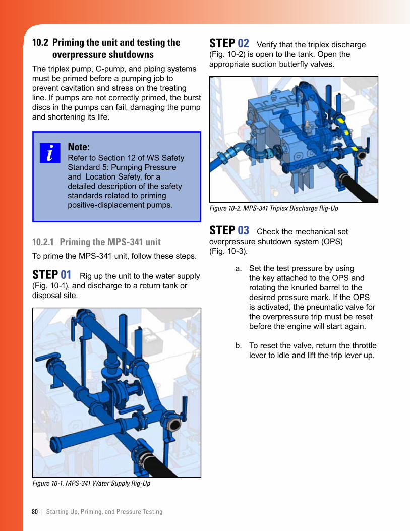
80 | Starting Up, Priming, and Pressure Testing
10.2 Priming the unit and testing the overpressure shutdowns
The triplex pump, C-pump, and piping systems must be primed before a pumping job to prevent cavitation and stress on the treating line. If pumps are not correctly primed, the burst discs in the pumps can fail, damaging the pump and shortening its life.
Note:Refer to Section 12 of WS Safety Standard 5: Pumping Pressure and Location Safety, for a detailed description of the safety standards related to priming positive-displacement pumps.
10.2.1 Priming the MPS-341 unit To prime the MPS-341 unit, follow these steps.
STEP 01 Rig up the unit to the water supply (Fig. 10-1), and discharge to a return tank or disposal site.
Figure 10-1. MPS-341 Water Supply Rig-Up
STEP 02 Verify that the triplex discharge (Fig. 10-2) is open to the tank. Open the appropriate suction butterfly valves.
Figure 10-2. MPS-341 Triplex Discharge Rig-Up
STEP 03 Check the mechanical set overpressure shutdown system (OPS) (Fig. 10-3).
Set the test pressure by using the key attached to the OPS and rotating the knurled barrel to the desired pressure mark. If the OPS is activated, the pneumatic valve for the overpressure trip must be reset before the engine will start again.
To reset the valve, return the throttle lever to idle and lift the trip lever up.
a.
b.
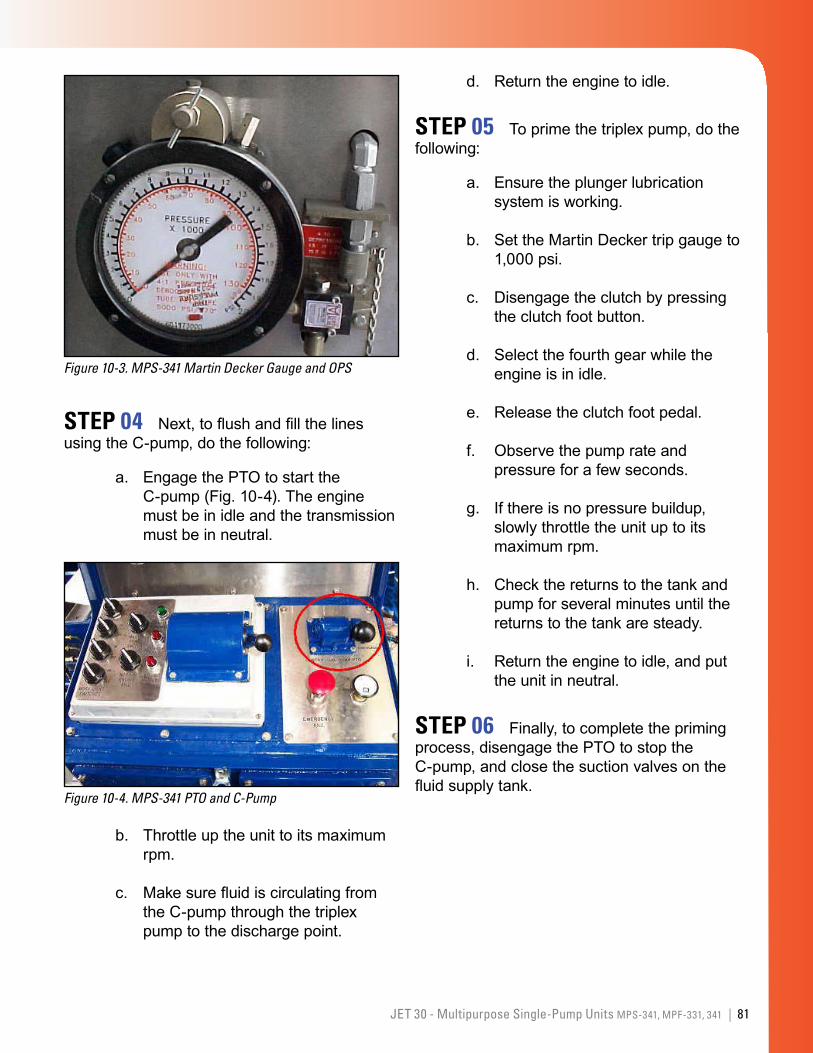
81JET 30 - Multipurpose Single-Pump Units MPS-341, MPF-331, 341 |
Figure 10-3. MPS-341 Martin Decker Gauge and OPS
STEP 04 Next, to flush and fill the lines using the C-pump, do the following:
Engage the PTO to start the C-pump (Fig. 10-4). The engine must be in idle and the transmission must be in neutral.
Figure 10-4. MPS-341 PTO and C-Pump
Throttle up the unit to its maximum rpm.
Make sure fluid is circulating from the C-pump through the triplex pump to the discharge point.
a.
b.
c.
Return the engine to idle.
STEP 05 To prime the triplex pump, do the following:
Ensure the plunger lubrication system is working.
Set the Martin Decker trip gauge to 1,000 psi.
Disengage the clutch by pressing the clutch foot button.
Select the fourth gear while the engine is in idle.
Release the clutch foot pedal.
Observe the pump rate and pressure for a few seconds.
If there is no pressure buildup, slowly throttle the unit up to its maximum rpm.
Check the returns to the tank and pump for several minutes until the returns to the tank are steady.
Return the engine to idle, and put the unit in neutral.
STEP 06 Finally, to complete the priming process, disengage the PTO to stop the C-pump, and close the suction valves on the fluid supply tank.
d.
a.
b.
c.
d.
e.
f.
g.
h.
i.
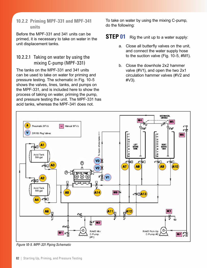
82 | Starting Up, Priming, and Pressure Testing
10.2.2 Priming MPF-331 and MPF-341 units
Before the MPF-331 and 341 units can be primed, it is necessary to take on water in the unit displacement tanks.
10.2.2.1 Taking on water by using the mixing C-pump (MPF-331)
The tanks on the MPF-331 and 341 units can be used to take on water for priming and pressure testing. The schematic in Fig. 10-5 shows the valves, lines, tanks, and pumps on the MPF-331, and is included here to show the process of taking on water, priming the pump, and pressure testing the unit. The MPF-331 has acid tanks, whereas the MPF-341 does not.
Figure 10-5. MPF-331 Piping Schematic
To take on water by using the mixing C-pump, do the following:
STEP 01 Rig the unit up to a water supply:
Close all butterfly valves on the unit, and connect the water supply hose to the suction valve (Fig. 10-5, #M1).
Close the downhole 2x2 hammer valve (#V1), and open the two 2x1 circulation hammer valves (#V2 and #V3).
a.
b.
83JET 30 - Multipurpose Single-Pump Units MPS-341, MPF-331, 341 |
STEP 02 To fill the curbside (left) displacement tank with water, do the following:
Open actuator valves #A12, #A11, #A13, #A14, and #A5.
Also open the displacement tank, fill valve #M8, and the splitter valve #M4 to fill the curbside tank.
Open the water valve at its source, and check for leaks.
Flood the plumbing by opening the suction inlet valve (#M1).
With the transmission still in neutral and engine at idle, engage C-pump #1 (mixing C-pump) by moving the PTO on the lower control console in. There is no need to engage C-pump #2. The C-pump will start turning and fluid will enter the displacement tank. Monitor this filling process by observing the rising float in the sight glass and looking inside the tank.
Increase the throttle to achieve the desired fill rate.
STEP 03 To stop filling the tank, do the following:
Either close valves #A11 or #M8, or slow the engine to idle.
Move the PTO out.
Filling the roadside tank is similar to the above process except that the complementary valves must be lined up to allow the flow of fluid to and from the displacement tanks.
If water is taken on board the unit by using C-pump #2 (the pick-up pump), then you will also need to hook up the water supply to #M7
a.
b.
c.
d.
e.
f.
a.
b.
or #M6, set up the actuator valves and hand valves correctly, and engage the air-clutch valve on the control console for C-pump #2.
10.2.2.2 Priming triplex pumps (MPF units)The triplex pumps can be primed by either the pressurized feed method using the the gravity feed method or C-pump method.
Gravity feed method
To prime the triplex pumps by using the gravity feed method, do the following:
STEP 01 Check and set the OPS (Fig. 10-3):
With the engine in neutral and idling at ±1,000 rpm, test the trip on the Martin Decker gauge by rolling the high alarm setting counterclockwise until it touch-es the indicator needle. The trip light should light up, and the engine speed should drop to low idle.
Reset the trip light by bringing the throttle lever all the way back until the trip light turns off.
STEP 02 Set the Martin Decker trip gauge (Fig. 10-6) to 1,000 psi.
1.
2.
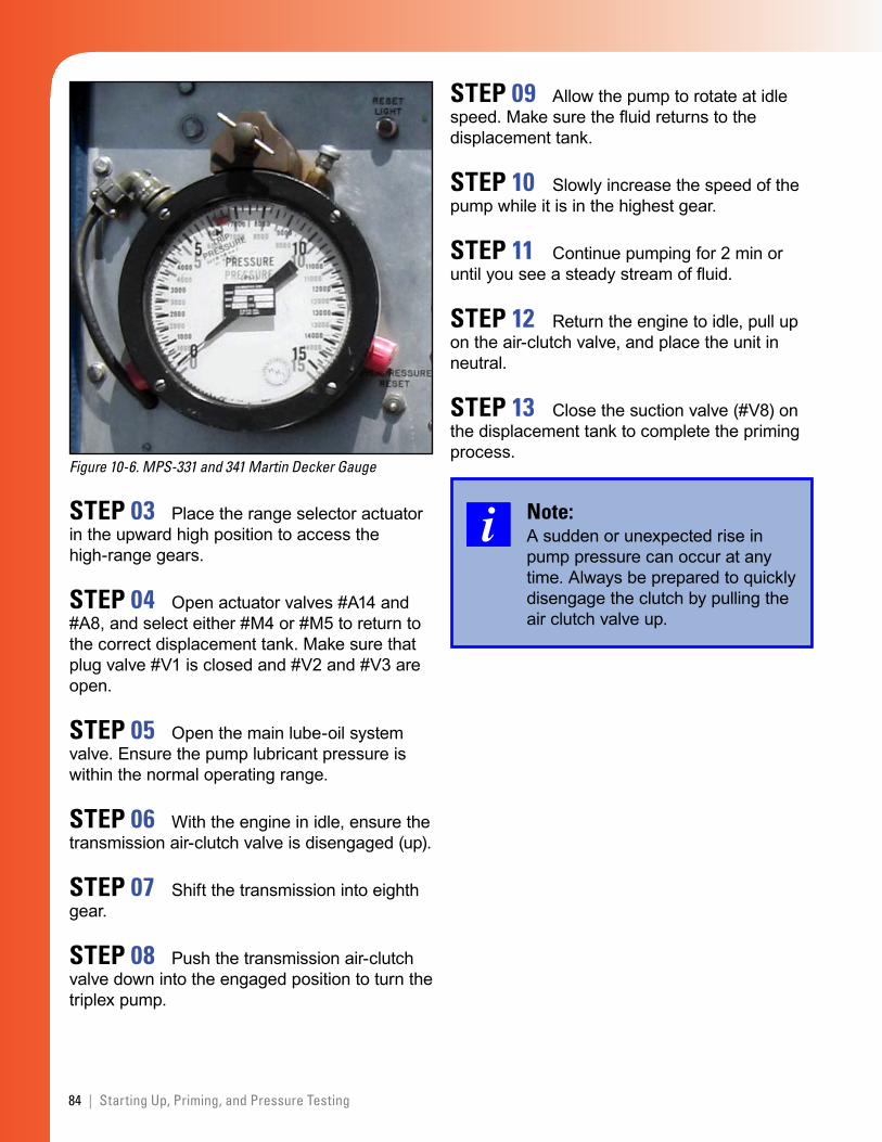
84 | Starting Up, Priming, and Pressure Testing
Figure 10-6. MPS-331 and 341 Martin Decker Gauge
STEP 03 Place the range selector actuator in the upward high position to access the high-range gears.
STEP 04 Open actuator valves #A14 and #A8, and select either #M4 or #M5 to return to the correct displacement tank. Make sure that plug valve #V1 is closed and #V2 and #V3 are open.
STEP 05 Open the main lube-oil system valve. Ensure the pump lubricant pressure is within the normal operating range.
STEP 06 With the engine in idle, ensure the transmission air-clutch valve is disengaged (up).
STEP 07 Shift the transmission into eighth gear.
STEP 08 Push the transmission air-clutch valve down into the engaged position to turn the triplex pump.
STEP 09 Allow the pump to rotate at idle speed. Make sure the fluid returns to the displacement tank.
STEP 10 Slowly increase the speed of the pump while it is in the highest gear.
STEP 11 Continue pumping for 2 min or until you see a steady stream of fluid.
STEP 12 Return the engine to idle, pull up on the air-clutch valve, and place the unit in neutral.
STEP 13 Close the suction valve (#V8) on the displacement tank to complete the priming process.
Note:A sudden or unexpected rise in pump pressure can occur at any time. Always be prepared to quickly disengage the clutch by pulling the air clutch valve up.
85JET 30 - Multipurpose Single-Pump Units MPS-341, MPF-331, 341 |
Pressurized-feed method
To prime the triplex pumps by using the pressurized feed method, do the following:
STEP 01 Check and set the OPS (Fig. 10-3):
With the engine in neutral and idling at ±1,000 rpm, test the trip on the Martin Decker gauge by rolling the high alarm setting counterclockwise until it touches the indicator needle. The trip light should light up, and the engine speed should drop to low idle.
Reset the trip light by bringing the throttle lever all the way back until the trip light turns off.
STEP 02 Set the Martin Decker trip gauge (Fig. 10-6) to 1,000 psi.
STEP 03 Place the range selector actuator in the upward high position to access the high-range gears.
STEP 04 Open valves #A7, #A11, #A12, #A13, and #A14 (Fig. 10-3) to feed the triplex from the mixing C-pump.
STEP 05 Ensure that plug valve #V1 is closed and #V2 and #V3 are open.
STEP 06 Engage the PTO.
STEP 07 Open actuator valves #A14 and #A8, and select either #M4 or #M5 to return to the correct displacement tank. Make sure that plug valve #V1 is closed and #V2 and #V3 are open.
a.
b.
STEP 08 Open the main lube-oil system valve. Ensure the pump lubricant pressure is within the normal operating range.
STEP 09 With the engine in idle, ensure the transmission air-clutch valve is disengaged (up).
STEP 10 Shift the transmission into eighth gear.
STEP 11 Push the transmission air-clutch valve down into the engaged position to turn the triplex pump.
STEP 12 Allow the pump to rotate at idle speed. Make sure the fluid returns to the displacement tank.
STEP 13 Slowly increase the speed of the pump while it is in the highest gear.
STEP 14 Continue pumping for 2 min or until you see a steady stream of fluid.
STEP 15 Return the engine to idle, pull up on the air-clutch valve, and place the unit in neutral.
STEP 16 Close the suction valve (#V8) on the displacement tank to complete the priming process.
Note:A sudden or unexpected rise in pump pressure can occur at any time. Always be prepared to quickly disengage the clutch by pulling the air clutch valve up.
86 | Starting Up, Priming, and Pressure Testing
10.3 Pressure and line testingBefore pressure testing, make sure the unit is primed, all personnel are clear of unit, and the unit has been rigged up according to WS Safety Standard 5: Pressure Pumping and Location Safety.
Warning:This unit produces very high pressures, even when the engine is in idle. Be very careful when you conduct the pressure test.
To check the pressure and test the line, do the following:
STEP 01 Walk the high-pressure discharge line to make sure the valves are open or closed correctly for the pressure test. The lines have been primed (see the section on unit priming above).
STEP 02 Make sure the data acquisition system is on and is working.
Note:All pressure tests must be recorded and documented.
STEP 03 Confirm that the OPSs are set at the correct pressure for testing (see the section on priming units above).
Note:Do not set the trip lever at a pressure that exceeds the maximum test pressure of the treating equipment or customer equipment.
STEP 04 With the engine in idle, put the unit in first gear. Pressure testing in first gear allows greater control of the triplex pump rotation.
Note:Do not engage the pump until the site supervisor or field engineer gives the approval.
STEP 05 Put the pump in first gear to rotate it slightly by quickly engaging and disengaging the clutch:
MPS-341: Depress the clutch foot button, and shift to first gear. Quickly release your foot and then push the foot button back down quickly. The triplex pump will rotate slightly while the transmission is engaging and disengaging.
MPF-331 and 341: Place the transmission in first gear, but do not engage the clutch. To engage the clutch, quickly press the air-clutch valve down and then pull it up immediately. Do not leave the clutch engaged for more than 1 or 2 seconds.
•
•
87JET 30 - Multipurpose Single-Pump Units MPS-341, MPF-331, 341 |
Note:Do not rely on the OPS system to reach the test pressure. The unit tends to overshoot the target pressure by several hundred psi. If the test pressure exceeds the test pressure, the trip lever will activate and disengage the clutch from the engine. If this happens, bleed some pressure and reset the trip lever to build pressure again to the target pressure.
STEP 06 Observe the drive line or plungers to verify that the pump moves. The pressure can increase several hundred psi at a time. Wait for a positive pressure indication on the Martin Decker gauge. A few seconds of delay may occur between the time the clutch is disengaged and the time the pressure is indicated.
STEP 07 Repeat the sequence of stabbing the clutch (pressing the foot pedal quickly for 1 or 2 seconds each time or turning the clutch valve but keeping it in the engaged position), until the desired test pressure is reached.
STEP 08 Place the unit in neutral when the target pressure is reached.
STEP 09 Monitor the pressure for the required duration of the test. Bleed the pressure as directed by the job supervisor before you continue.
STEP 10 Stop the test and pause the data acquisition.

88 | Starting Up, Priming, and Pressure Testing
This page left intentionally blank
89JET 30 - Multipurpose Single-Pump Units MPS-341, MPF-331, 341 |
11.0 PumpingOperationProcedures
The pumping operations performed using the MPS-341, MPF-331, and MPF-341 pump units usually take a long time and have relatively low rates and high pressures. Long pumping operations can become boring, and an operator risks getting tired and losing attention.
11.1 General considerationsIn all pumping operations, especially long pumping jobs, remember to do these things:
Be familiar with the objectives of the treatment and have a copy of the job procedure detailing the steps of the operation. This procedure should also detail the types of fluids to be prepared and pumped, volumes, required rates, expected pressures, and potential hazards. Discuss the capacity and pressure limits of the coiled tubing with the CT supervisor.
For expected treatment pressures and rates, determine the following:
the gear(s) to be selected for treatment (see the section on pump rate selection)
the maximum expected hydraulic horse-power requirements for the job:
hhp = Pressure (psi) x Rate (bbl/min) 40.8
Discuss contingencies before the job so that you know what to do if there is a change in plans or a significant event that affects the treatment occurs.
Put plans in place to prepare additional or new fluids during the pumping operation. Materials must be on hand, clearly marked, and inventoried.
•
•
○
○
•
•
Establish lines of communication and agree on your responsibilities and the job supervisor’s before the job starts.
As the job proceeds, follow the treatment steps and stages.
Do a complete STEM I check before you start the pumping operation.
Ensure diesel fuel for the engines is available and that refueling during a job has been arranged.
Ensure additional lubricant-oil is available for the triplex and C-pumps and that a procedure for adding oil during pumping operations has been arranged.
Observe and monitor the engine, transmission, and pump gauges throughout the pumping operation.
Check the pumps and lines regularly for leaks.
As the operator, you should pay special attention to these things to keep from losing attention:
Ensure plans are in place for a competent person to replace you for regular breaks during the treatment, especially if pump times are to exceed 4 hr.
Ensure you are well rested before the job so that you do not fall asleep during the pumping operation.
Use the operator’s seat provided, but do not sit in it for long periods without moving around.
Use the umbrella provided as protection from the rain or sun.
•
•
•
•
•
•
•
•
•
•
•
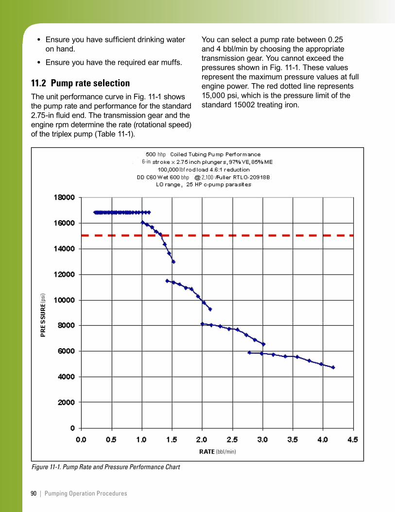
90 | Pumping Operation Procedures
Ensure you have sufficient drinking water on hand.
Ensure you have the required ear muffs.
11.2 Pump rate selectionThe unit performance curve in Fig. 11-1 shows the pump rate and performance for the standard 2.75-in fluid end. The transmission gear and the engine rpm determine the rate (rotational speed) of the triplex pump (Table 11-1).
Figure 11-1. Pump Rate and Pressure Performance Chart
hhp
bhp 2,100
(bbl/min)
(psi
)
6-inlbf
•
•
You can select a pump rate between 0.25 and 4 bbl/min by choosing the appropriate transmission gear. You cannot exceed the pressures shown in Fig. 11-1. These values represent the maximum pressure values at full engine power. The red dotted line represents 15,000 psi, which is the pressure limit of the standard 15002 treating iron.
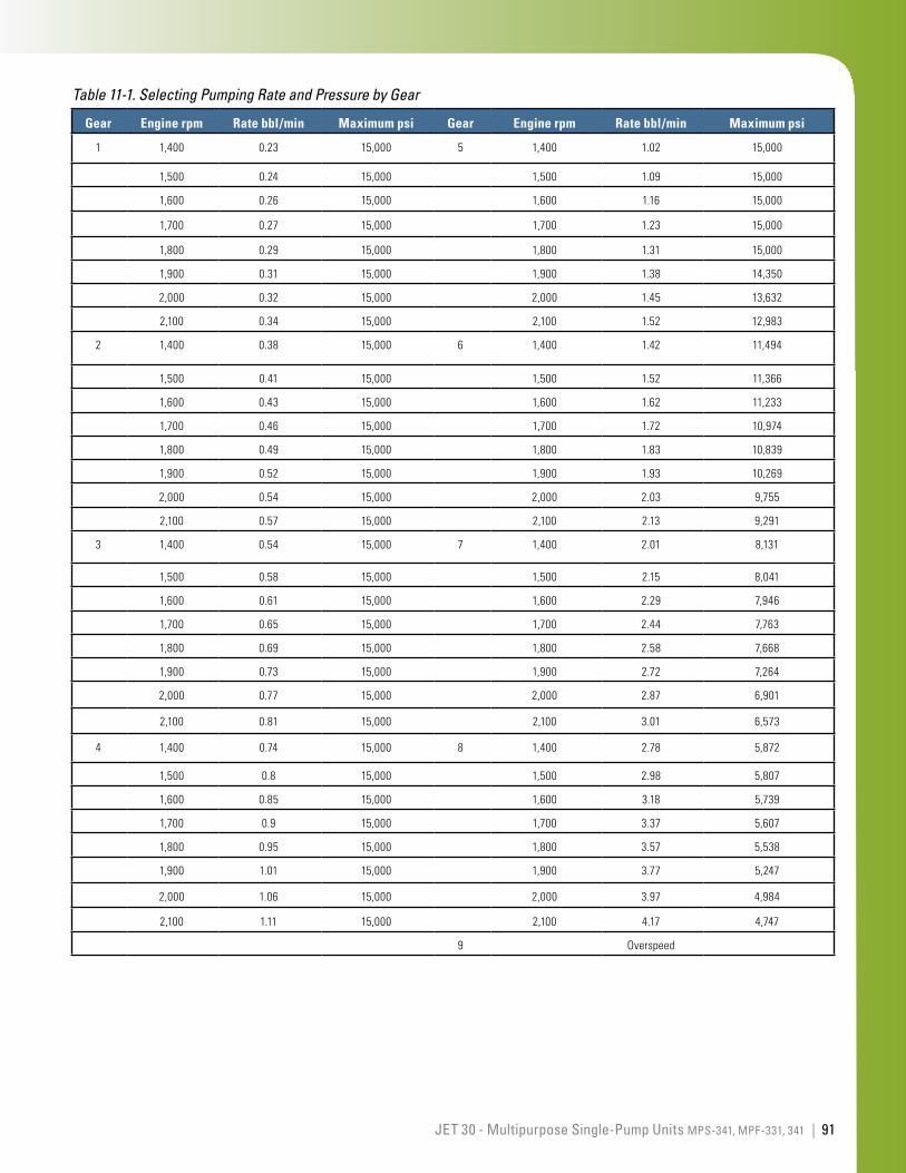
91JET 30 - Multipurpose Single-Pump Units MPS-341, MPF-331, 341 |
Gear Engine rpm Rate bbl/min Maximum psi Gear Engine rpm Rate bbl/min Maximum psi
1 1,400 0.23 15,000 5 1,400 1.02 15,000
1,500 0.24 15,000 1,500 1.09 15,000
1,600 0.26 15,000 1,600 1.16 15,000
1,700 0.27 15,000 1,700 1.23 15,000
1,800 0.29 15,000 1,800 1.31 15,000
1,900 0.31 15,000 1,900 1.38 14,350
2,000 0.32 15,000 2,000 1.45 13,632
2,100 0.34 15,000 2,100 1.52 12,983
2 1,400 0.38 15,000 6 1,400 1.42 11,494
1,500 0.41 15,000 1,500 1.52 11,366
1,600 0.43 15,000 1,600 1.62 11,233
1,700 0.46 15,000 1,700 1.72 10,974
1,800 0.49 15,000 1,800 1.83 10,839
1,900 0.52 15,000 1,900 1.93 10,269
2,000 0.54 15,000 2,000 2.03 9,755
2,100 0.57 15,000 2,100 2.13 9,291
3 1,400 0.54 15,000 7 1,400 2.01 8,131
1,500 0.58 15,000 1,500 2.15 8,041
1,600 0.61 15,000 1,600 2.29 7,946
1,700 0.65 15,000 1,700 2.44 7,763
1,800 0.69 15,000 1,800 2.58 7,668
1,900 0.73 15,000 1,900 2.72 7,264
2,000 0.77 15,000 2,000 2.87 6,901
2,100 0.81 15,000 2,100 3.01 6,573
4 1,400 0.74 15,000 8 1,400 2.78 5,872
1,500 0.8 15,000 1,500 2.98 5,807
1,600 0.85 15,000 1,600 3.18 5,739
1,700 0.9 15,000 1,700 3.37 5,607
1,800 0.95 15,000 1,800 3.57 5,538
1,900 1.01 15,000 1,900 3.77 5,247
2,000 1.06 15,000 2,000 3.97 4,984
2,100 1.11 15,000 2,100 4.17 4,747
9 Overspeed
Table 11-1. Selecting Pumping Rate and Pressure by Gear
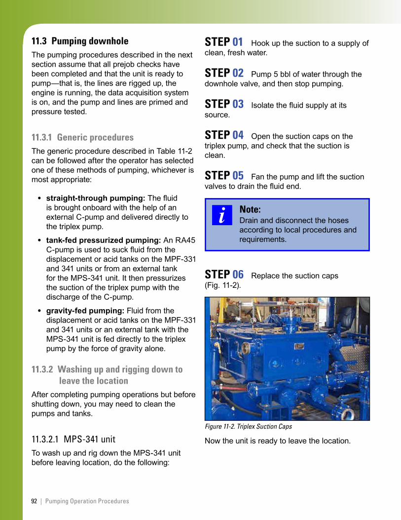
92 | Pumping Operation Procedures
11.3 Pumping downholeThe pumping procedures described in the next section assume that all prejob checks have been completed and that the unit is ready to pump—that is, the lines are rigged up, the engine is running, the data acquisition system is on, and the pump and lines are primed and pressure tested.
11.3.1 Generic proceduresThe generic procedure described in Table 11-2 can be followed after the operator has selected one of these methods of pumping, whichever is most appropriate:
straight-through pumping: The fluid is brought onboard with the help of an external C-pump and delivered directly to the triplex pump.
tank-fed pressurized pumping: An RA45 C-pump is used to suck fluid from the displacement or acid tanks on the MPF-331 and 341 units or from an external tank for the MPS-341 unit. It then pressurizes the suction of the triplex pump with the discharge of the C-pump.
gravity-fed pumping: Fluid from the displacement or acid tanks on the MPF-331 and 341 units or an external tank with the MPS-341 unit is fed directly to the triplex pump by the force of gravity alone.
11.3.2 Washing up and rigging down to leave the location
After completing pumping operations but before shutting down, you may need to clean the pumps and tanks.
11.3.2.1 MPS-341 unitTo wash up and rig down the MPS-341 unit before leaving location, do the following:
•
•
•
STEP 01 Hook up the suction to a supply of clean, fresh water.
STEP 02 Pump 5 bbl of water through the downhole valve, and then stop pumping.
STEP 03 Isolate the fluid supply at its source.
STEP 04 Open the suction caps on the triplex pump, and check that the suction is clean.
STEP 05 Fan the pump and lift the suction valves to drain the fluid end.
Note:Drain and disconnect the hoses according to local procedures and requirements.
STEP 06 Replace the suction caps (Fig. 11-2).
Figure 11-2. Triplex Suction Caps
Now the unit is ready to leave the location.
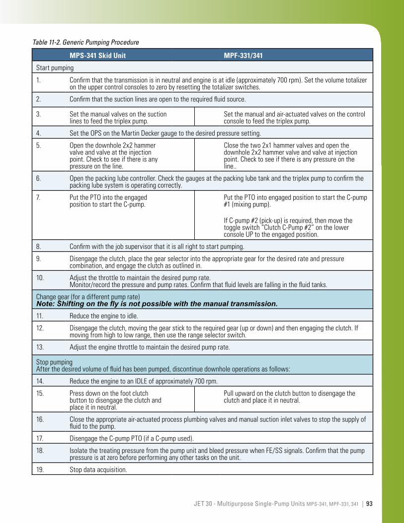
93JET 30 - Multipurpose Single-Pump Units MPS-341, MPF-331, 341 |
MPS-341 Skid Unit MPF-331/341
Startpumping
1. Confirmthatthetransmissionisinneutralandengineisatidle(approximately700rpm).Setthevolumetotalizerontheuppercontrolconsolestozerobyresettingthetotalizerswitches.
2. Confirmthatthesuctionlinesareopentotherequiredfluidsource.
3. Setthemanualvalvesonthesuctionlinestofeedthetriplexpump.
Setthemanualandair-actuatedvalvesonthecontrolconsoletofeedthetriplexpump.
4. SettheOPSontheMartinDeckergaugetothedesiredpressuresetting.
5. Openthedownhole2x2hammervalveandvalveattheinjectionpoint.Checktoseeifthereisanypressureontheline.
Closethetwo2x1hammervalvesandopenthedownhole2x2hammervalveandvalveatinjectionpoint.Checktoseeifthereisanypressureontheline..
6. Openthepackinglubecontroller.Checkthegaugesatthepackinglubetankandthetriplexpumptoconfirmthepackinglubesystemisoperatingcorrectly.
7. PutthePTOintotheengagedpositiontostarttheC-pump.
PutthePTOintoengagedpositiontostarttheC-pump#1(mixingpump).
IfC-pump#2(pick-up)isrequired,thenmovethetoggleswitch“ClutchC-Pump#2”onthelowerconsoleUPtotheengagedposition.
8. Confirmwiththejobsupervisorthatitisallrighttostartpumping.
9. Disengagetheclutch,placethegearselectorintotheappropriategearforthedesiredrateandpressurecombination,andengagetheclutchasoutlinedin.
10. Adjustthethrottletomaintainthedesiredpumprate.Monitor/recordthepressureandpumprates.Confirmthatfluidlevelsarefallinginthefluidtanks.
Changegear(foradifferentpumprate)Note: Shifting on the fly is not possible with the manual transmission.11. Reducetheenginetoidle.
12. Disengagetheclutch,movingthegearsticktotherequiredgear(upordown)andthenengagingtheclutch.Ifmovingfromhightolowrange,thenusetherangeselectorswitch.
13. Adjusttheenginethrottletomaintainthedesiredpumprate.
StoppumpingAfterthedesiredvolumeoffluidhasbeenpumped,discontinuedownholeoperationsasfollows:
14. ReducetheenginetoanIDLEofapproximately700rpm.
15. Pressdownonthefootclutchbuttontodisengagetheclutchandplaceitinneutral.
Pullupwardontheclutchbuttontodisengagetheclutchandplaceitinneutral.
16. Closetheappropriateair-actuatedprocessplumbingvalvesandmanualsuctioninletvalvestostopthesupplyoffluidtothepump.
17. DisengagetheC-pumpPTO(ifaC-pumpused).
18. IsolatethetreatingpressurefromthepumpunitandbleedpressurewhenFE/SSsignals.Confirmthatthepumppressureisatzerobeforeperforminganyothertasksontheunit.
19. Stopdataacquisition.
Table 11-2. Generic Pumping Procedure
94 | Pumping Operation Procedures
11.3.2.2 MPF-331 and 341 unitsTo wash up and rig down the MPF-331 or MPF-341 unit before leaving location, do the following:
STEP 01 Start with at least 10 bbl of clean, fresh water in either displacement tank, in the acid tanks, or in an external tank.
STEP 02 Isolate the fluid supply at its source.
STEP 03 Set the internal manifold to circulation; that is, close the downhole 2x2 valve (#V1; see Fig. 10-5), and OPEN the two circulation 2x1 valves (#V2 and #V3).
STEP 04 Configure the air-actuation valves and manual suction valves to circulate clean water through the previously used process plumbing.
STEP 05 Set the internal manifold to downhole; that is, open the downhole 2x2 valve and close the two circulation 2x1 valves.
STEP 06 Pump 2 to 3 bbl of water through the downhole valve, and then stop pumping.
STEP 07 Open the suction caps on the triplex pump.
STEP 08 Pump the remaining fluid off the unit.
STEP 09 Replace the suction caps.
11.4 Shutting down and leaving locationTo shut the unit down and leave the location, do the following:
STEP 01 Move the air-actuated valves and/or manual valves to the desired position for unit storage or transport. Leave all the hammer valves open.
STEP 02 Turn the packing lube controller to the closed position. Bleed off the pressure in the lubricant-oil tank and refill.
STEP 03 With the engine in idle, allow the engine to cool for 5 min.
STEP 04 Shut down the engine with the STOP control on the control console.
STEP 05 Shut off the work lights.
STEP 06 Turn the main power switch off, and/or turn the main battery disconnect switch off.
STEP 07 Disconnect the sensor cables and replace the end caps. Store the sensor cables safely.
STEP 08 Rig down the treating iron and hoses. Secure the iron, hoses, and other loose items on the trailer or skid.
11.5 Cold weather operationsIn cold environments, take special care to ensure that water is fully drained from the unit to prevent freezing and damage. After the pumping operations but before leaving location, do the following:
STEP 01 Ensure that the emergency tank suction valve is open.
95JET 30 - Multipurpose Single-Pump Units MPS-341, MPF-331, 341 |
STEP 02 Open all air-actuated valves (see Fig. 10-3) before shutting down the unit. An air supply is required to activate the valves.
STEP 03 Open all the manual butterfly inlet valves.
STEP 04 Open the fill control valve.
STEP 05 Open the internal manifold valves, that is, two recirculation 2x1 hammer valves and one downhole 2x2 hammer valve.
STEP 06 Open the drain valves (ball valves) at the base of each C-pump housing.
STEP 07 Remove the suction caps from the triplex.
STEP 08 Drain the suction valves:
Insert a curved rod into the pump un-til it touches the bottom of the suction valves.
Push up on each valve to drain any residual fluid.
STEP 09 Confirm that all fluids have drained from the displacement tanks, the acid tanks, the process piping, and the inside of the triplex pump.
1.
2.
11.6 Special tasks specific to the MPF-331 and 341 units
Two tasks are specific to the displacement and acid tanks found on the MPF-331 and 341 units but not the MPS-341 unit: displacement tank mixing and acid tank mixing.
Note:Personnel operating the pump unit during the mixing and circulating process must wear the appropriate PPE.
11.6.1 Mixing and circulating the displacement tank contents
There are several techniques for mixing and circulating the contents of the displacement tanks. One common technique (assuming that the roadside (left of the driver) displacement tank contents are circulated) uses the C-pump; another uses the triplex pump.
11.6.1.1 Method 1: using C-pump #1To mix and circulate the contents of the roadside displacement tanks using the C-pump, do the following:
STEP 01 Ensure that the tank selector valve is positioned to the left and that the fill control valve is open.
STEP 02 Close actuator valves #A5, #A8, #A9, #A10, #A12, and #A14 (see Fig. 10-3).
STEP 03 Open actuator valves #A7 and #A11.
STEP 04 Engage C-pump #1 by placing the PTO in the in position, as described above.
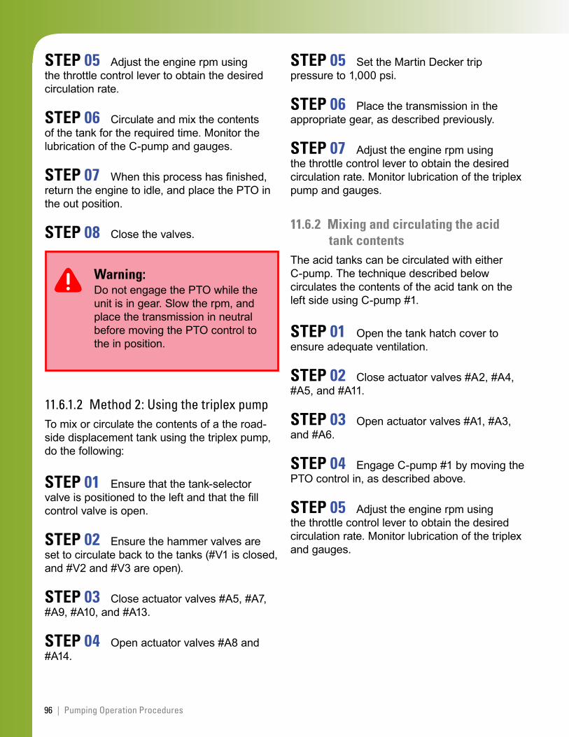
96 | Pumping Operation Procedures
STEP 05 Adjust the engine rpm using the throttle control lever to obtain the desired circulation rate.
STEP 06 Circulate and mix the contents of the tank for the required time. Monitor the lubrication of the C-pump and gauges.
STEP 07 When this process has finished, return the engine to idle, and place the PTO in the out position.
STEP 08 Close the valves.
Warning:Do not engage the PTO while the unit is in gear. Slow the rpm, and place the transmission in neutral before moving the PTO control to the in position.
11.6.1.2 Method 2: Using the triplex pumpTo mix or circulate the contents of a the road-side displacement tank using the triplex pump, do the following:
STEP 01 Ensure that the tank-selector valve is positioned to the left and that the fill control valve is open.
STEP 02 Ensure the hammer valves are set to circulate back to the tanks (#V1 is closed, and #V2 and #V3 are open).
STEP 03 Close actuator valves #A5, #A7, #A9, #A10, and #A13.
STEP 04 Open actuator valves #A8 and #A14.
STEP 05 Set the Martin Decker trip pressure to 1,000 psi.
STEP 06 Place the transmission in the appropriate gear, as described previously.
STEP 07 Adjust the engine rpm using the throttle control lever to obtain the desired circulation rate. Monitor lubrication of the triplex pump and gauges.
11.6.2 Mixing and circulating the acid tank contents
The acid tanks can be circulated with either C-pump. The technique described below circulates the contents of the acid tank on the left side using C-pump #1.
STEP 01 Open the tank hatch cover to ensure adequate ventilation.
STEP 02 Close actuator valves #A2, #A4, #A5, and #A11.
STEP 03 Open actuator valves #A1, #A3, and #A6.
STEP 04 Engage C-pump #1 by moving the PTO control in, as described above.
STEP 05 Adjust the engine rpm using the throttle control lever to obtain the desired circulation rate. Monitor lubrication of the triplex and gauges.
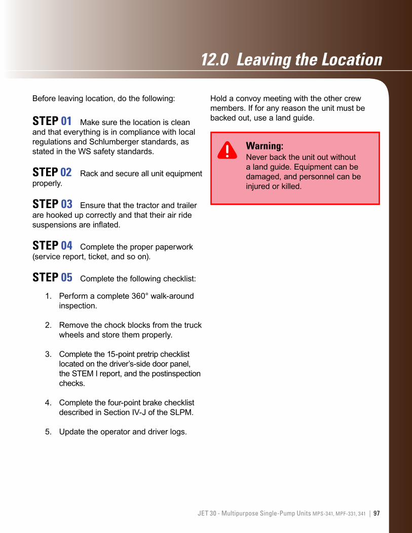
97JET 30 - Multipurpose Single-Pump Units MPS-341, MPF-331, 341 |
12.0 LeavingtheLocation
Before leaving location, do the following:
STEP 01 Make sure the location is clean and that everything is in compliance with local regulations and Schlumberger standards, as stated in the WS safety standards.
STEP 02 Rack and secure all unit equipment properly.
STEP 03 Ensure that the tractor and trailer are hooked up correctly and that their air ride suspensions are inflated.
STEP 04 Complete the proper paperwork (service report, ticket, and so on).
STEP 05 Complete the following checklist:
Perform a complete 360° walk-around inspection.
Remove the chock blocks from the truck wheels and store them properly.
Complete the 15-point pretrip checklist located on the driver’s-side door panel, the STEM I report, and the postinspection checks.
Complete the four-point brake checklist described in Section IV-J of the SLPM.
Update the operator and driver logs.
1.
2.
3.
4.
5.
Hold a convoy meeting with the other crew members. If for any reason the unit must be backed out, use a land guide.
Warning:Never back the unit out without a land guide. Equipment can be damaged, and personnel can be injured or killed.

98 | Leaving the Location
This page left intentionally blank
99JET 30 - Multipurpose Single-Pump Units MPS-341, MPF-331, 341 |
13.0 Troubleshooting
To help eliminate equipment problems that need troubleshooting, perform maintenance, prejob, and postjob STEM checks proactively. Make sure the equipment remains clean and corrosion free, and carefully plan a job before it begins.
Proactive activities include prompt reporting and documenting of potential problems by bringing them to the attention of maintenance personnel and carefully following up to ensure that the necessary spare parts are available and that the repairs have been made.
Troubleshooting guides are available for the MPS-341, MPF-331, and 341 units in the relevant operating and maintenance manuals (see Section 15: References). These manuals cover the following components:
engine
transmission
triplex pumps
C-pumps
electric system
air system
packing lube system.
•
•
•
•
•
•
•

This page left intentionally blank
100 | Troubleshooting
101JET 30 - Multipurpose Single-Pump Units MPS-341, MPF-331, 341 |
14.0 MaintenanceProcedures
The following maintenance procedures are important for the MPS-341, MPF-331, and 341 units:
prejob and postjob inspections detailed in this JET manual
STEM I inspections, required before and after every job; a STEM 1 report form for the MPF-341 provided in Appendix A
STEM II procedures, performed every 150 h or 90 days, whichever comes first; these are detailed in the relevant multipurpose pump maintenance manuals
red tag/green tag system for marking the status of equipment maintenance
required safety PPE and equipment, to be used when maintenance is being done on the unit
use of a lockout tag on the starter when an engine is being worked on while it is shut down, ensuring that no one starts the engine without the operator’s knowledge (WS Safety Standard 15: Lockout - Tagout, InTouch Content ID# 3313691)
Caution:Before starting the engine, ensure that everyone is clear of the engine area.
•
•
•
•
•
•
Note:Equipment modifications are not allowed without the proper approvals.

102 | Maintenance Procedures
This page left intentionally blank
103JET 30 - Multipurpose Single-Pump Units MPS-341, MPF-331, 341 |
15.0 References
All Schlumberger employees must be familiar with the relevant safety standards and precautions because of the many hazards involved in the oilfield industry.
Be sure that you know the Contents of the relevant MSDS regarding required PPE and handling procedures for chemicals.
15.1 Oilfield Services QHSE standardsStandard S001: Journey Management and Driving, InTouch Content ID# 3051691
Standard S002: QHSE Reporting, InTouch Content ID# 3260257
Standard S003: Personal Protective Equipment, InTouch Content ID# 3260259
Standard S004: Emergency Response, InTouch Content ID# 3253244
Standard S013: Mechanical Lifting, InTouch Content ID# 3260276
15.2 Well Services safety standardsSafety Standard 4: Facilities and Workshops, InTouch Content ID# 3313678
Safety Standard 5: Pressure Pumping and Location Safety, InTouch Content ID# 3313681
Safety Standard 11: Pumping Nitrogen, InTouch Content ID# 3313684
Safety Standard 15: Lockout/Tagout, InTouch Content ID# 3313691
Safety Standard 17: Storage and Handling of Oxidizers, InTouch Content ID# 3313693
Safety Standard 18: HAZCOM, InTouch Content ID# 3313694
Safety Standard 22: Coiled Tubing Operations, InTouch Content ID# 3313710
Safety Standard 26: Air Tanks and Receivers, InTouch Content ID# 3313706
Safety Standard 27: Inspection and Testing of Pressure Relief Valves and Gauges, InTouch Content ID# 3313707
Safety Standard 30: Pumping Combustible and Flammable Fluids, InTouch Content ID# 3313709
15.3 JET manualsInTouch JET reference page, InTouch Content ID# 4178854
15.4 Unit manualsA series of manuals, technology-based training manuals, and other information relating to the three multipurpose pump units are available in InTouch as follows:
MPS-341 Multipurpose Pumping Skid Operations Manual, InTouch Content ID# 3759506
MPS-341 Multipurpose Pumping Skid Maintenance Manual, InTouch Content ID# 3759508
104 | References
MPS-341 Multipurpose Pumping Skid Technology-Based Training, InTouch Content ID# 3759509
MPS-341 Vendor Maintenance Manual Volume 1, V 1.1, InTouch Content ID# 3652634 (including Gardner Denver 594PN008 and 594PN027 manuals (operations, service, parts for the triplex OPI pump), 4x5 centrifugal pump manual [maintenance, parts])
MPS-341 Vendor Maintenance Manual Volume 2, V1.1, InTouch Content ID# 3764159 Gardner Denver OPI-600 Triplex Pump, InTouch Content ID# 4183702
MPF-331/341 Operations Manual V 1.0, InTouch Content ID# 3652554
MPF-331/341 Vendor Maintenance Manual, InTouch Content ID# 3553221
MPF-331 Multipurpose Pumping Float Technology-Based Training, InTouch Content ID# 3759509
Gardner Denver OPI-600 Triplex Pump, InTouch Content ID# 4183702
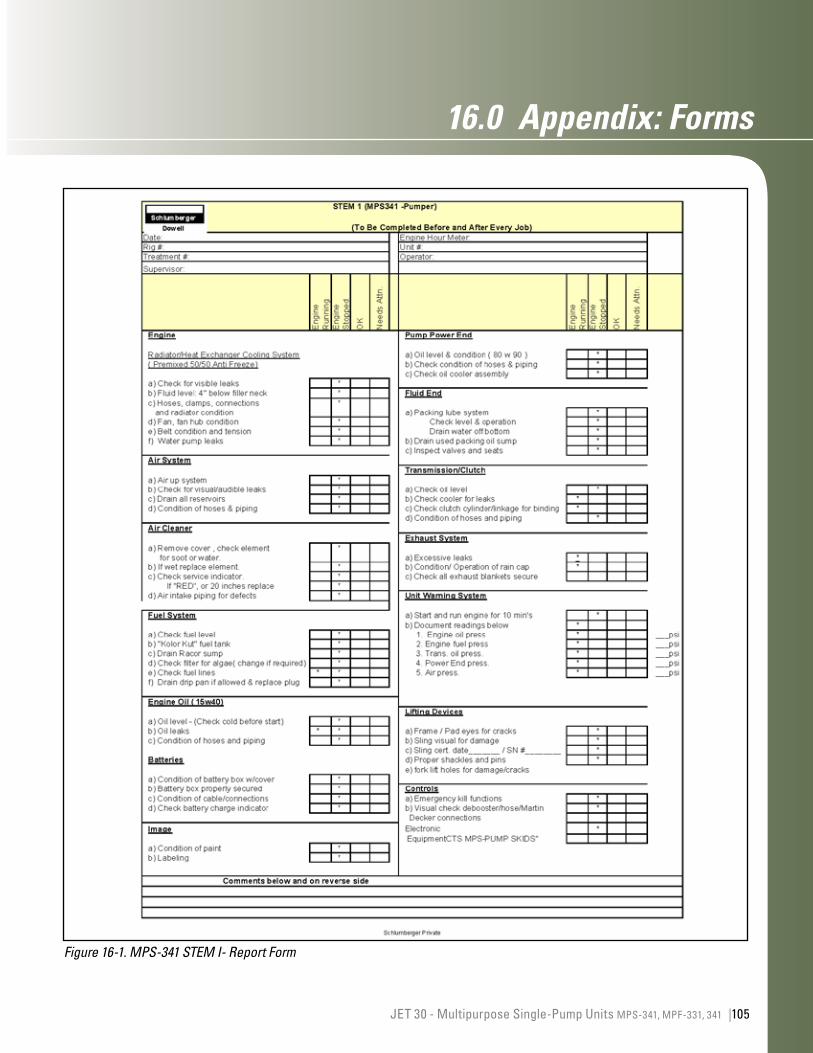
105JET 30 - Multipurpose Single-Pump Units MPS-341, MPF-331, 341 |
16.0 Appendix:Forms
Figure 16-1. MPS-341 STEM I- Report Form
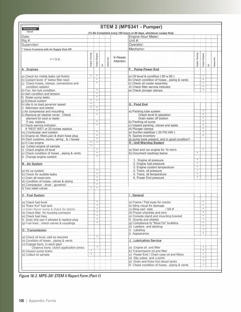
106 | Appendix: Forms
Figure 16-2. MPS-341 STEM II Report Form (Part-1)
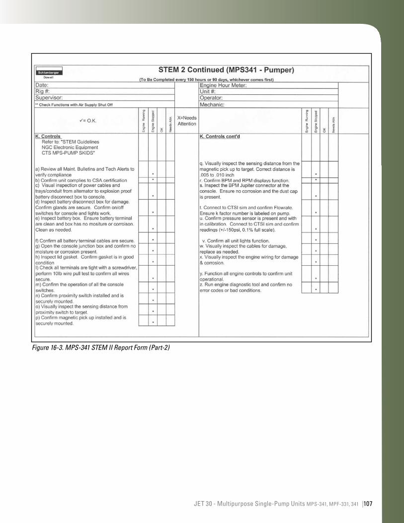
107JET 30 - Multipurpose Single-Pump Units MPS-341, MPF-331, 341 |
Figure 16-3. MPS-341 STEM II Report Form (Part-2)
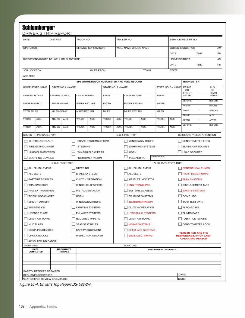
108 | Appendix: Forms
DATE DISTRICT TRUCK NO. TRAILER NO. SERVICE RECEIPT NO.
OPERATOR SERVICE SUPERVISOR WELL NAME OR JOB NAME JOB SCHEDULE FOR AM
DATE TIME PM
DIRECTIONS ROUTE TO WELL OR PLANT SITE LEAVE DISTRICT AM
DATE TIME PM
JOB LOCATION MILES FROM TOWN STATE
ADDRESS
SPEEDOMETER OR HUBOMETER AND FUEL RECORD HOURMETER
HOME STATE NAME STATE NO.1 - NAME STATE NO. 2 - NAME STATE NO. 3 - NAME PRIME AUX OR OR
FRONT REARARRIVE DISTRICT LEAVING GOING LEAVE RETURN LEAVE LEAVE RETURN LEAVE AFTER AFTER
LEAVE DISTRICT ENTER GOING ENTER RETURN ENTER ENTER RETURN ENTER
TOTAL MILES MILES GOING MILES RETURN MILES MILES RETURN MILES
TRUCK AUX. TRUCK AUX. TRUCK AUX. TRUCK AUX. TRUCK AUX. TRUCK AUX.
TRUCK AUX. TRUCK AUX. TRUCK AUX. TRUCK AUX. TRUCK AUX. TRUCK AUX.
CHECK ( ) INDICATES “OK” D.O.T. PRE-TRIP (X) MEANS “NEEDS ATTENTION
BEFORE BEFORE
HOURS HOURS
PUMP STROKE
PRIME AUX.
AFTER AFTER
BEFORE BEFORE
OIL/FUEL/COOLANT
FIRE EXTINGUISHER
LUGS/CLAMPS/TIRES
COUPLING DEVICES
BRAKE SYSTEMS/4 POINT
STEERING
WINGSHIELD WIPERS
INSTRUMENTACION
WINDOWS/MIRRORS
LIGHTNING SYSTEMS
HORN
PLACARDING
DENSITOMETER LOCK
BLINDS/CAPS/DOMES
LOAD SECURED
ALL FLUID LEVELS
ALL BELTS
AIR FILET INDICATOR
ENG./TRANS./PTO
BATTERIES/CABLES
EXHAUST SYSTEMS
INSTRUMENTACION
CLUTCH OPERATION
HYDRAULIC SYSTEMS
DRAIN AIR TANKS
MIXING SYSTEMS
CHEM. ADD SYSTEMS
SUCT./DISC. PIPING
STEERING
BRAKE SYSTEMS
CLUTCH OPERATION
WINDSHIELD WIPERS
INSTRUMENTACION
HORN
WINDOWS/MIRRORS
LIGHTING SYSTEMS
EXHAUST SYSTEMS
REQUIRED PAPERS
SEAT/SEAT BELTS
SAFETY EQUIPMENT
INSPECTION STICKER
ALL FLUID LEVELS
ALL BELTS
BATTERIES/CABLES
TRANSMISSION
FIRE EXTINGUISHER
TIRES/LUGS/CLAMPS
DRIVETRAIN/DIFF.
SUSPENSION
LICENSE PLATE
DRAIN AIR TANKS
MUD FLAPS
COUPLING DEVICES
CHOCK BLOCKS
AIR FILTER INDICATOR
CENTRIFUGAL PUMPS
HIGH PRESS. PUMPS
BULK SYSTEMS
DISPLACEMENT TANK
SAFETY SYSTEMS
DOME LIDS
TANK TEST DATE
PLACARDING
BLINDS/CAPS
RADIATION PAPERS
DENSITOMETER LOCK
ITEMS IN RED ARE THE RESPONSABILITY OF LAST
OPERATING PERSON
DATE COMPLETED
MECHANIC’S INITIALS
DESCRIPTION OF DEFECT
SIGNATURE: SIGNATURE:
SAFETY DEFECTS REPAIRED
MECHANIC SIGNATURE:NEXT DRIVER REVIEW SIGNATURE: DATE:
DATE:
D.O.T. POST-TRIP AUXILIARY POST-TRIP
SIGNATURE:
SchlumbergerDRIVER’S TRIP REPORT
Figure 16-4. Driver’s Trip Report DS-598-2-A
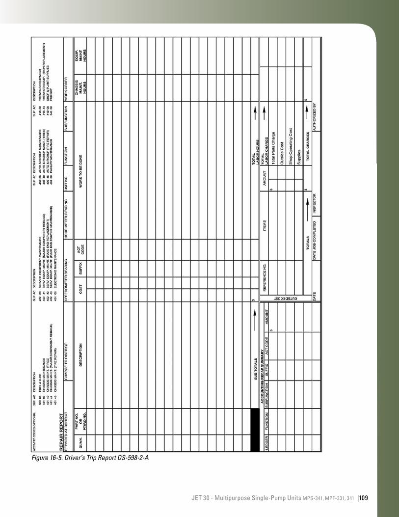
109JET 30 - Multipurpose Single-Pump Units MPS-341, MPF-331, 341 |
Figure 16-5. Driver’s Trip Report DS-598-2-A
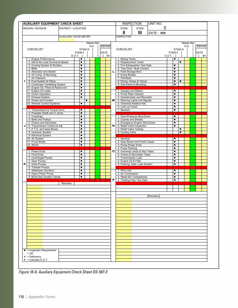
110 | Appendix: Forms
AUXILIARY EQUIPMENT CHECK SHEET INSPECTION UNIT NO.REGION / DIVISION DISTRICT / LOCATION STEM STEM 0
II III DATE : ###AUXILIARY HOUR METER INSPECTOR
Needs Attn. Needs Attn.O.K. | REPAIR O.K. | REPAIR
CHECKLIST STEM III | | CHECKLIST STEM III | |STEM II | | | DATE STEM II | | | DATE
D.O.T. | | | | | BY D.O.T. | | | | | BY 1. Engine Preformance 1. Mixing Tanks 2. Idle & No Load Goverend Speed 2. Displacement Tanks 3. Cooling System & Shutters 3. Fire Extinguisher Test Date 4. Belts 4. Tear Drop - Bulk Cement 5. Alternator and Starter L 5. Field Storage Bins 6. Air Comp. & Mounting 6. Dump Bodies 7. Air Cleaners 7. Flat Beds
I 8. Fuel System & Filters 8. Piping, Hoses & Valves 9. Crankcase Ventilating System 9. Sub-frame & Mounting10. Engine Oil, Filters & Reservoirs11. Engine Oil Leaks 1. Gauges and Meters12. Clutch Operation 2. Pump Rate Indicator13. Exhaust System 3. Densitometer and Recorder14. Hoses and Coolant M 4. Warning Lights and Signals15. Remote Control Systems 5. Chemical Additive Kits
6. Lock-up Clutch 1. Transmission & Torque Conv. 7. Sensors 2. Propeller Shaft and U Joints 3. Couplings 1. Over-Pressure Shut-Down 4. Belts and Pulleys 2. Guards and Shields 5. Chains and Sprockets 3. Emergency Engine Shut-Down
J 6. Transmission Control & Adj. N 4. Relief Valve Inspection 7. P.T.O. and Gear Boxes 5. Relief Valve Testing 8. Hydraulic System 6. Cycling Valve 9. Electrical System10. Air System 1. General11. Pump Brake 2. Gear Boxes and Chain Cases12. Winch 3. Pump Power Ends
4. Pump Packing 1. Power Ends O 5. Universal Joints & Slip Yokes 2. Fluid Ends 6. Chains & Sprockets, Open 3. Centrifugal Pumps 7. Transmission Lube 4. Gear Pumps 8. Engine Oil & Filter
K 5. Vane Pumps 9. Packing, Seal, Lube System 6. Tublular Pumps 7. Stabilizers (Suction) 1. Wire Line 8. Hypro Piston Pump 2. Air Compressor 9. Burst Disc Suction Valves 3. "Must Do" Compliances
P 4. Treating Pipe Test DateRemarks
Remarks
= Inspection Requirement= OK
x = Deficiency= Indicates D.O.T.
Figure 16-6. Auxiliary Equipment Check Sheet DS-587-E
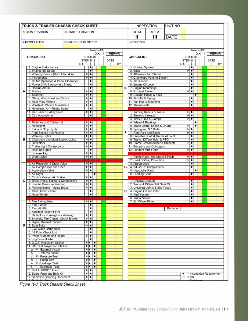
111JET 30 - Multipurpose Single-Pump Units MPS-341, MPF-331, 341 |
TRUCK & TRAILER CHASSIS CHECK SHEET INSPECTION UNIT NO.REGION / DIVISION DISTRICT / LOCATION STEM STEM
II III DATE :HUBODOMETER PRIMARY HOUR METER INSPECTOR
Needs Attn. Needs Attn.O.K. | REPAIR O.K. | REPAIR
CHECKLIST STEM III | | CHECKLIST STEM III | |STEM II | | | DATE STEM II | | | DATE
D.O.T. | | | | | BY D.O.T. | | | | | BY 1. Engine Preformance 1. Cooling System 2. Engine Idle Speed 2. Belts 3. Warning Device (Horn Elec. & Air) 3. Alternator and Starter 4. Instruments 4. Crankcase Venting System 5. Clutch Operation & Pedal Clearance 5. Air Cleaner 6. Power Shift & Automatic Trans. 6. Engine Oil Level 7. Backup Alarm E 7. Engine Mountings
A 8. Brakes 8. Exhaust System 9. Steering 9. Coolant Hoses & Fluid10. Glass, Windshield and Doors 10. Air Inlet & Piping11. Rear View Mirrors 11. Fan Hub & Mounting12. Winshield Wipers & Washers 12. Thermostats13. Headliner, Arm Rests, Seats14. Cab Jack & Saftey Latch 1. Turning Radius & Toe-in15. Cab Accessories 2. Steering Linkage
3. Tires, Rims & Clamps 1. Batteries and Cables (1) 4. Wheel & Bearings 2. Headlights 5. Brake Lining, Shoes & Drums 3. Tail and Stop Lights 6. Spring and "U" Bolts 4. Turn Signals and Flasher F 7. Rear Axle and Bogie 5. Warning Lights 8. Propeller Shaft & Universal Joint
B 6. Clearance and Identification Lights 9. Trans., Differentials, & PTO 7. Reflectors 10. Frame Crossmember & Brackets 8. Trailer Light Connections 11. Bumpers and Outriggers 9. Back-up Lights 12. Fenders Mud Flaps10. License Tag11. Work Lights 1. Pentle Hook, 5th Wheel & Hitch
2. Load Shifting Protection 1. Air Reservoir & Drain Valve 3. Appearance 2. Air Compressor and Filter G 4. "Must Do" Compliances 3. Application Valve 5. Headache Rack 4. Air Dryer 6. Landing Gear 5. Control Valves, Air Brakes
C 6. Brake-Hose, Tubing & Connections 1. Chassis General 7. Low Air Pressure Warning 2. Trans. & Differential Gear Oil 8. Parking Brake - Maxie Brake 3. Universal Joints & Slip Yokes 9. Glad Hand Covers H 4. Engine Oil and Filter10. Hose Tender 5. Fuel System
6. Transmission 1. Fire Extinguisher 7. 5th Wheel Plate 2. Fire Blanket 3. First Aid Kit Remarks 4. Accident Report Form 5. Reflectors - Emergency Warning 6. Shovels, Tire Chains, Chock Blocks 7. Signs, Material Placard
D 8. Seat Belts 9. Eye Wash Bottle Rack10. 14 Point Check List11. Proper Papers and Holder12. Log Book Holder13. D.O.T. Inspection Sticker14. HM Tank Inspection Sticker a. V - External Visual b. I - Internal Visual c. P - Pressure Test d. L - Lining Test e. K - Leakage Test f. T - Thickness Test15. Unit #, USDOT #, etc. 16. Spare Fuse and Bulb Kit = Inspectrion Requirement17. Radiation Shipping Document = OK18. Radiation Manual x = Deficiency
= Indicates D.O.T.
14.a-f Attach HM Tank Inspection Form when inspecting a HM Tank Unit (01 A,B,E;29 C,E,G,H; 30 A; 37 D; 16 A,B,C,D...etc.).Verify DOT stickers during STEM II, replace stickers during STEM III
Figure 16-7. Truck Chassis Check Sheet

112 | Appendix: Forms
This page left intentionally blank
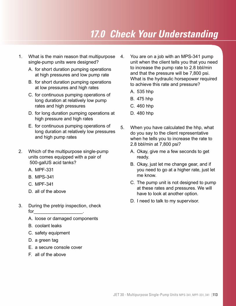
17.0 CheckYourUnderstanding
113JET 30 - Multipurpose Single-Pump Units MPS-341, MPF-331, 341 |
1. What is the main reason that multipurpose single-pump units were designed?A. for short duration pumping operations
at high pressures and low pump rateB. for short duration pumping operations
at low pressures and high ratesC. for continuous pumping operations of
long duration at relatively low pump rates and high pressures
D. for long duration pumping operations at high pressure and high rates
E. for continuous pumping operations of long duration at relatively low pressures and high pump rates
2. Which of the multipurpose single-pump units comes equipped with a pair of 500-galUS acid tanks?A. MPF-331B. MPS-341C. MPF-341D. all of the above
3. During the pretrip inspection, check for___________________. A. loose or damaged componentsB. coolant leaksC. safety equipmentD. a green tagE. a secure console coverF. all of the above
4. You are on a job with an MPS-341 pump unit when the client tells you that you need to increase the pump rate to 2.8 bbl/min and that the pressure will be 7,800 psi. What is the hydraulic horsepower required to achieve this rate and pressure?A. 535 hhpB. 475 hhpC. 460 hhpD. 480 hhp
5. When you have calculated the hhp, what do you say to the client representative when he tells you to increase the rate to 2.8 bbl/min at 7,800 psi? A. Okay, give me a few seconds to get
ready.B. Okay, just let me change gear, and if
you need to go at a higher rate, just let me know.
C. The pump unit is not designed to pump at these rates and pressures. We will have to look at another option.
D. I need to talk to my supervisor.
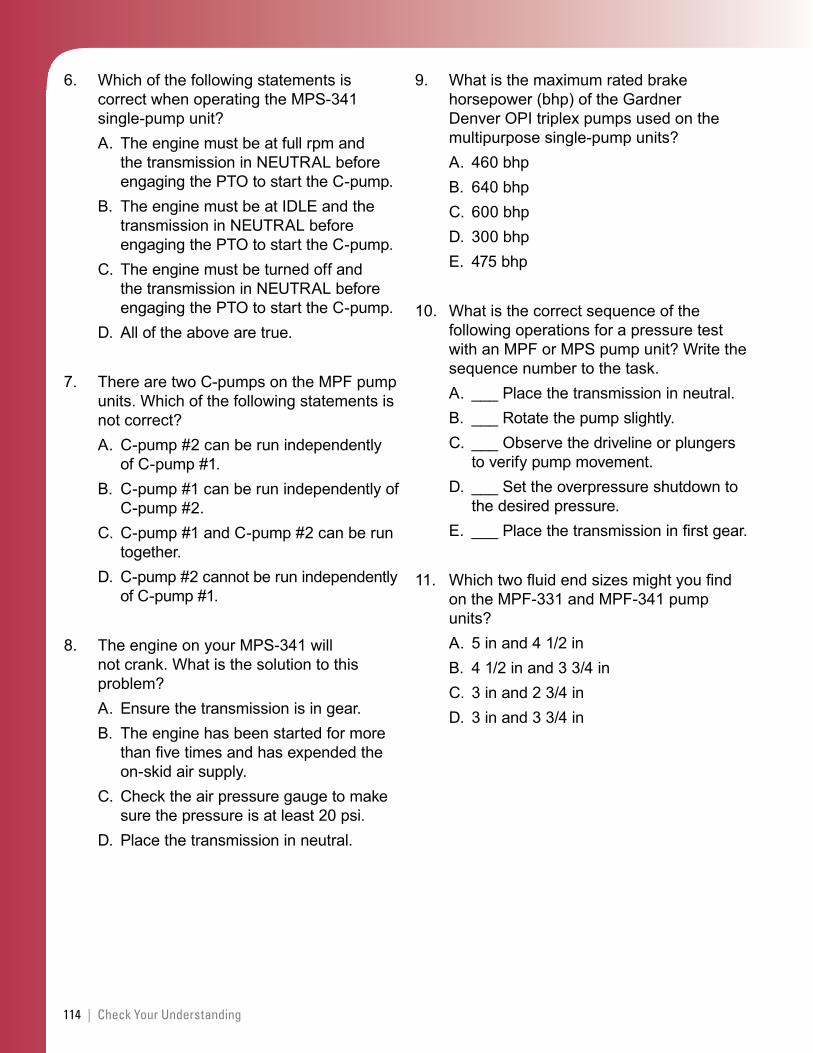
114 | Check Your Understanding
6. Which of the following statements is correct when operating the MPS-341 single-pump unit?A. The engine must be at full rpm and
the transmission in NEUTRAL before engaging the PTO to start the C-pump.
B. The engine must be at IDLE and the transmission in NEUTRAL before engaging the PTO to start the C-pump.
C. The engine must be turned off and the transmission in NEUTRAL before engaging the PTO to start the C-pump.
D. All of the above are true.
7. There are two C-pumps on the MPF pump units. Which of the following statements is not correct?A. C-pump #2 can be run independently
of C-pump #1.B. C-pump #1 can be run independently of
C-pump #2.C. C-pump #1 and C-pump #2 can be run
together.D. C-pump #2 cannot be run independently
of C-pump #1.
8. The engine on your MPS-341 will not crank. What is the solution to this problem?A. Ensure the transmission is in gear.B. The engine has been started for more
than five times and has expended the on-skid air supply.
C. Check the air pressure gauge to make sure the pressure is at least 20 psi.
D. Place the transmission in neutral.
9. What is the maximum rated brake horsepower (bhp) of the Gardner Denver OPI triplex pumps used on the multipurpose single-pump units?A. 460 bhpB. 640 bhpC. 600 bhpD. 300 bhpE. 475 bhp
10. What is the correct sequence of the following operations for a pressure test with an MPF or MPS pump unit? Write the sequence number to the task.A. ___ Place the transmission in neutral.B. ___ Rotate the pump slightly.C. ___ Observe the driveline or plungers
to verify pump movement.D. ___ Set the overpressure shutdown to
the desired pressure.E. ___ Place the transmission in first gear.
11. Which two fluid end sizes might you find on the MPF-331 and MPF-341 pump units?A. 5 in and 4 1/2 inB. 4 1/2 in and 3 3/4 inC. 3 in and 2 3/4 inD. 3 in and 3 3/4 in
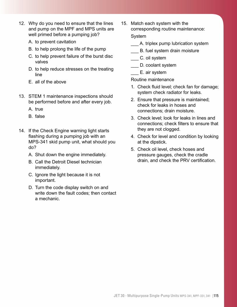
115JET 30 - Multipurpose Single-Pump Units MPS-341, MPF-331, 341 |
12. Why do you need to ensure that the lines and pump on the MPF and MPS units are well primed before a pumping job?A. to prevent cavitationB. to help prolong the life of the pumpC. to help prevent failure of the burst disc
valvesD. to help reduce stresses on the treating
lineE. all of the above
13. STEM 1 maintenance inspections should be performed before and after every job.A. trueB. false
14. If the Check Engine warning light starts flashing during a pumping job with an MPS-341 skid pump unit, what should you do?A. Shut down the engine immediately.B. Call the Detroit Diesel technician
immediately.C. Ignore the light because it is not
important.D. Turn the code display switch on and
write down the fault codes; then contact a mechanic.
15. Match each system with the corresponding routine maintenance:System___ A. triplex pump lubrication system___ B. fuel system drain moisture___ C. oil system___ D. coolant system___ E. air systemRoutine maintenance1. Check fluid level; check fan for damage;
system check radiator for leaks.2. Ensure that pressure is maintained;
check for leaks in hoses and connections; drain moisture.
3. Check level; look for leaks in lines and connections; check filters to ensure that they are not clogged.
4. Check for level and condition by looking at the dipstick.
5. Check oil level, check hoses and pressure gauges, check the cradle drain, and check the PRV certification.

116 | Check Your Understanding
This page left intentionally blank


![slurry jet pump ahmed · 2019-01-02 · al [13].They concluded that, the performance of both solid handling jet pump and water jet pump are effected by nozzle –throat ratio and](https://img.pdfslide.net/doc/110x75/5f0ed4667e708231d4412481/slurry-jet-pump-ahmed-2019-01-02-al-13they-concluded-that-the-performance.jpg)