Embed Size (px)
Citation preview
READ THIS DOCUMENT IN TOTALITY PRIOR TO START THE INSTALLATION.
WWW.BURCAM.COM
2190 Dagenais Blvd. West TEL: 514.337.4415 LAVAL (QUEBEC) FAX: 514.337.4029 CANADA H7L 5X9 [email protected]
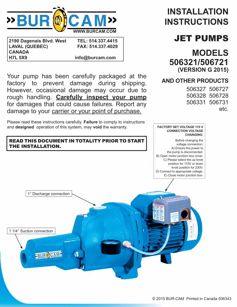
Your pump has been carefully packaged at the factory to prevent damage during shipping. However, occasional damage may occur due to rough handling. Carefully inspect your pump for damages that could cause failures. Report any damage to your carrier or your point of purchase.Please read these instructions carefully. Failure to comply to instructions and designed operation of this system, may void the warranty. FACTORY SET VOLTAGE 115 V
CONNECTION VOLTAGE CHANGING:
Before changing the voltage connection:
A) Ensure the power to the pump is disconnected.
B) Open motor junction box cover.C) Please select the up knob
position for 115V or down knob position for 230V.
D) Connect to appropriate voltage.E) Close motor junction box.
INSTALLATIONINSTRUCTIONS
JET PUMPSMODELS
506321/506721 (VERSION G 2015)
AND OTHER PRODUCTS506327 506727506328 506728506331 506731
etc.
© 2015 BUR-CAM Printed in Canada 506343
1’’ Discharge connection
1 1/4’’ Suction connection
2
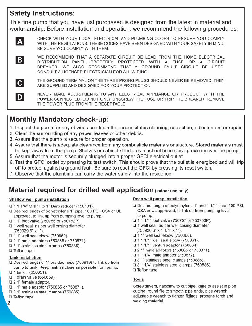
Safety Instructions:This fine pump that you have just purchased is designed from the latest in material and workmanship. Before installation and operation, we recommend the following procedures:
CHECK WITH YOUR LOCAL ELECTRICAL AND PLUMBING CODES TO ENSURE YOU COMPLY WITH THE REGULATIONS. THESE CODES HAVE BEEN DESIGNED WITH YOUR SAFETY IN MIND. BE SURE YOU COMPLY WITH THEM.
WE RECOMMEND THAT A SEPARATE CIRCUIT BE LEAD FROM THE HOME ELECTRICAL DISTRIBUTION PANEL PROPERLY PROTECTED WITH A FUSE OR A CIRCUIT BREAKER. WE ALSO RECOMMEND THAT A GROUND FAULT CIRCUIT BE USED. CONSULT A LICENSED ELECTRICIAN FOR ALL WIRING.
THE GROUND TERMINAL ON THE THREE PRONG PLUGS SHOULD NEVER BE REMOVED. THEY ARE SUPPLIED AND DESIGNED FOR YOUR PROTECTION.
NEVER MAKE ADJUSTMENTS TO ANY ELECTRICAL APPLIANCE OR PRODUCT WITH THE POWER CONNECTED. DO NOT ONLY UNSCREW THE FUSE OR TRIP THE BREAKER, REMOVE THE POWER PLUG FROM THE RECEPTACLE.
A
B
C
D
Material required for drilled well application (indoor use only)
Shallow well pump installation 1 1 1/4’’ MNPT to 1’’ Barb reducer (150181). Desired length of polyethylene 1” pipe, 100 PSI, CSA or UL
approved, to link up from pumping level to pump. 1 1” foot valve (750756 or 750752P). 1 well seal, as per well casing diameter
(750929 6” x 1”). 1 1” well seal elbow (750860). 2 1” male adaptors (750865 or 750871). 8 1” stainless steel clamps (750885). Teflon tape.Tank installation Desired length of 1” braided hose (750919) to link up from
pump to tank. Keep tank as close as possible from pump. 1 tank T (650651). 1 drain valve (650659). 2 1” female adaptor. 1 1” male adaptor (750865 or 750871). 3 1” stainless steel clamps (750885). Teflon tape.
ToolsScrewdrivers, hacksaw to cut pipe, knife to assist in pipe cutting, round file to smooth pipe ends, pipe wrench, adjustable wrench to tighten fittings, propane torch and welding material.
Monthly Mandatory check-up:1. Inspect the pump for any obvious condition that necessitates cleaning, correction, adjustement or repair.2. Clear the surrounding of any paper, leaves or other debris.3. Assure that the pump is secure for proper operation.4. Assure that there is adequate clearance from any combustible materials or stucture. Stored materials must
be kept away from the pump. Shelves or cabinet structures must not be in close proximity over the pump.5. Assure that the motor is securely plugged into a proper GFCI electrical outlet6. Test the GFCI outlet by pressing its test switch. This should prove that the outlet is energized and will trip
off to protect against a ground fault. Be sure to reset the GFCI by pressing its reset switch.7. Observe that the plumbing can carry the water safely into the residence.
Deep well pump installation Desired length of polyethylene 1” and 1 1/4” pipe, 100 PSI,
CSA or UL approved, to link up from pumping level to pump.
1 1 1/4” foot valve (750757 or 750753P). 1 well seal, as per well casing diameter (750926 6” x 1 1/4” x 1”). 1 1” well seal elbow (750860). 1 1 1/4” well seal elbow (750861). 1 1 1/4” venturi adaptor (750864). 2 1” male adaptors (750865 or 750871). 1 1 1/4” male adaptor (750872). 8 1” stainless steel clamps (750885). 8 1 1/4” stainless steel clamps (750886). Teflon tape.
3
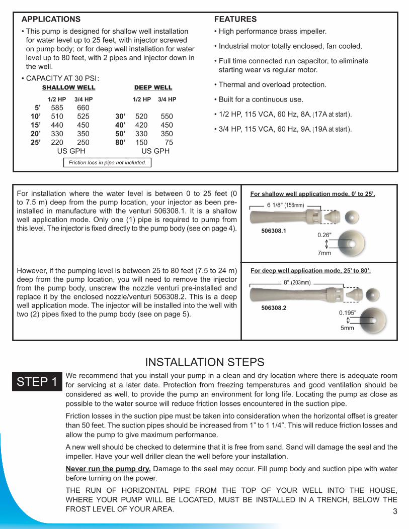
APPLICATIONS• This pump is designed for shallow well installation
for water level up to 25 feet, with injector screwed on pump body; or for deep well installation for water level up to 80 feet, with 2 pipes and injector down in the well.
• CAPACITY AT 30 PSI : SHALLOW WELL DEEP WELL
1/2 HP 3/4 HP 1/2 HP 3/4 HP 5’ 585 660 10’ 510 525 30’ 520 550 15’ 440 450 40’ 420 450 20’ 330 350 50’ 330 350 25’ 220 250 80’ 150 75 US GPH US GPH
FEATURES• High performance brass impeller.
• Industrial motor totally enclosed, fan cooled.
• Full time connected run capacitor, to eliminate starting wear vs regular motor.
• Thermal and overload protection.
• Built for a continuous use.
• 1/2 HP, 115 VCA, 60 Hz, 8A, (17A at start ).
• 3/4 HP, 115 VCA, 60 Hz, 9A, (19A at start ).
Friction loss in pipe not included.
INSTALLATION STEPSWe recommend that you install your pump in a clean and dry location where there is adequate room for servicing at a later date. Protection from freezing temperatures and good ventilation should be considered as well, to provide the pump an environment for long life. Locating the pump as close as possible to the water source will reduce friction losses encountered in the suction pipe.
Friction losses in the suction pipe must be taken into consideration when the horizontal offset is greater than 50 feet. The suction pipes should be increased from 1” to 1 1/4”. This will reduce friction losses and allow the pump to give maximum performance.
A new well should be checked to determine that it is free from sand. Sand will damage the seal and the impeller. Have your well driller clean the well before your installation.
Never run the pump dry. Damage to the seal may occur. Fill pump body and suction pipe with water before turning on the power.
THE RUN OF HORIZONTAL PIPE FROM THE TOP OF YOUR WELL INTO THE HOUSE, WHERE YOUR PUMP WILL BE LOCATED, MUST BE INSTALLED IN A TRENCH, BELOW THE FROST LEVEL OF YOUR AREA.
STEP 1
For installation where the water level is between 0 to 25 feet (0 to 7.5 m) deep from the pump location, your injector as been pre-installed in manufacture with the venturi 506308.1. It is a shallow well application mode. Only one (1) pipe is required to pump from this level. The injector is fixed directly to the pump body (see on page 4).
However, if the pumping level is between 25 to 80 feet (7.5 to 24 m) deep from the pump location, you will need to remove the injector from the pump body, unscrew the nozzle venturi pre-installed and replace it by the enclosed nozzle/venturi 506308.2. This is a deep well application mode. The injector will be installed into the well with two (2) pipes fixed to the pump body (see on page 5).
For deep well application mode, 25’ to 80’.
For shallow well application mode, 0’ to 25’.
506308.1
506308.2
6 1/8" (156mm)
8" (203mm)
0.26"
7mm
0.195"
5mm

4
SHALLOW WELL APPLICATIONSEE DIAGRAM ON PAGE 8
Cut the desired length of poly pipe to run from the top of the well to the pumping level. Smooth the pipe cuttings with your round file. (Check that no cut-out parts are left inside of pipe. This may block pump injector or impeller). Tape male adaptor threads with teflon tape and thread adaptor into the foot valve. Slide 2 stainless steel clamps over one end of pipe and use torch to soften pipe. Insert the male adaptor and foot valve into this pipe end. Tighten clamps with screwdriver when cool. For security against leaks, we suggest to install 2 stainless steel clamps on each adaptor.
Insert the well seal elbow thru the opening of the seal.Slide 2 stainless steel clamps over the free end of the previously cut pipe and soften pipe with your torch. Attach pipe to the well seal elbow (end protruding at bottom of well seal). Tighten clamps with screwdriver when cool.
Install the well seal and piping assembly into your well casing. Tight down the well seal bolts using your adjustable wrench.
Install your pump in the house, on a sound foundation, as close as possible to the basement wall. Locate the suction inlet in the front of the injector. Thread an adaptor into inlet using teflon tape. Do not over tighten.
Cut the desired length of pipe from pump location to the well seal and connect both ends using the previous way, with stainless steel clamps and torch. Do not fill in your trench to the house until you have checked for any leaks in your connections or trouble in your water system.
Sand or well points are limited to areas where water bearing sand or gravel lies below the surface, and where there are no boulders or rocks to interfere with the driving into the ground of the point.The amount of water any “one” well point will supply is usually rather limited. Sometimes, it is necessary to use more than one point to increase the supply of water, entering to the pump’s suction.
THE IMPORTANT INSTALLATION STEP IN USING WELL POINTS IS THAT A CHECK VALVE MUST BE USED IN THE SUCTION PIPE LEADING TO THE SUCTION INLET, AS CLOSE TO THE PUMP AS POSSIBLE, TO KEEP SUCTION LINE AND PUMP WELL PRIMED.
To facilitate servicing at a later date, you may use a pitless adaptor and a sealed well cap instead of an elbow and a well seal as describe in steps 3 and 4.
CONTINUE ON PAGE 6 FOR TANKS AND ON PAGE 7 FOR ELECTRICAL INSTALLATION STEPS.
STEP 2
STEP 3
STEP 4
STEP 5
STEP 6
STEP 7for sandor wellpoints
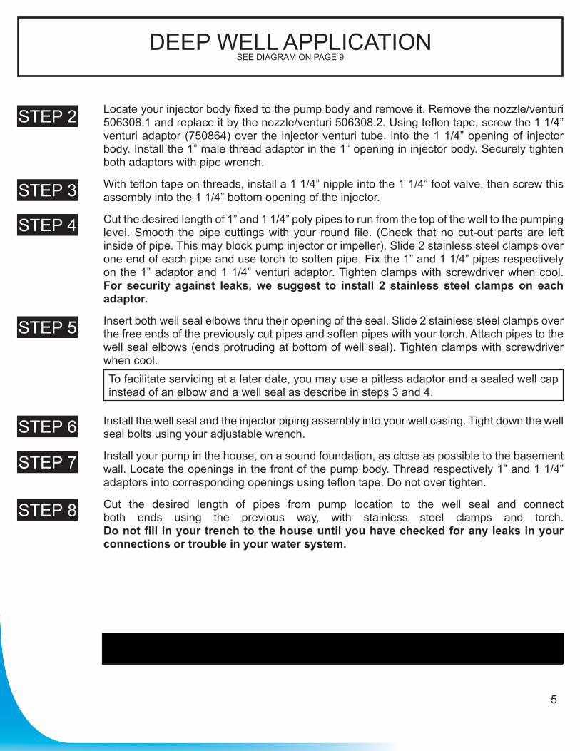
DEEP WELL APPLICATIONSEE DIAGRAM ON PAGE 9
Locate your injector body fixed to the pump body and remove it. Remove the nozzle/venturi 506308.1 and replace it by the nozzle/venturi 506308.2. Using teflon tape, screw the 1 1/4” venturi adaptor (750864) over the injector venturi tube, into the 1 1/4” opening of injector body. Install the 1” male thread adaptor in the 1” opening in injector body. Securely tighten both adaptors with pipe wrench.
With teflon tape on threads, install a 1 1/4” nipple into the 1 1/4” foot valve, then screw this assembly into the 1 1/4” bottom opening of the injector.
Cut the desired length of 1” and 1 1/4” poly pipes to run from the top of the well to the pumping level. Smooth the pipe cuttings with your round file. (Check that no cut-out parts are left inside of pipe. This may block pump injector or impeller). Slide 2 stainless steel clamps over one end of each pipe and use torch to soften pipe. Fix the 1” and 1 1/4” pipes respectively on the 1” adaptor and 1 1/4” venturi adaptor. Tighten clamps with screwdriver when cool. For security against leaks, we suggest to install 2 stainless steel clamps on each adaptor.
Insert both well seal elbows thru their opening of the seal. Slide 2 stainless steel clamps over the free ends of the previously cut pipes and soften pipes with your torch. Attach pipes to the well seal elbows (ends protruding at bottom of well seal). Tighten clamps with screwdriver when cool.
Install the well seal and the injector piping assembly into your well casing. Tight down the well seal bolts using your adjustable wrench.
Install your pump in the house, on a sound foundation, as close as possible to the basement wall. Locate the openings in the front of the pump body. Thread respectively 1” and 1 1/4” adaptors into corresponding openings using teflon tape. Do not over tighten.
Cut the desired length of pipes from pump location to the well seal and connect both ends using the previous way, with stainless steel clamps and torch. Do not fill in your trench to the house until you have checked for any leaks in your connections or trouble in your water system.
To facilitate servicing at a later date, you may use a pitless adaptor and a sealed well cap instead of an elbow and a well seal as describe in steps 3 and 4.
CONTINUE ON PAGE 6 FOR TANKS AND ON PAGE 7 FOR ELECTRICAL INSTALLATION STEPS.
STEP 2
STEP 3
STEP 4
STEP 5
STEP 6
STEP 7
STEP 8
5
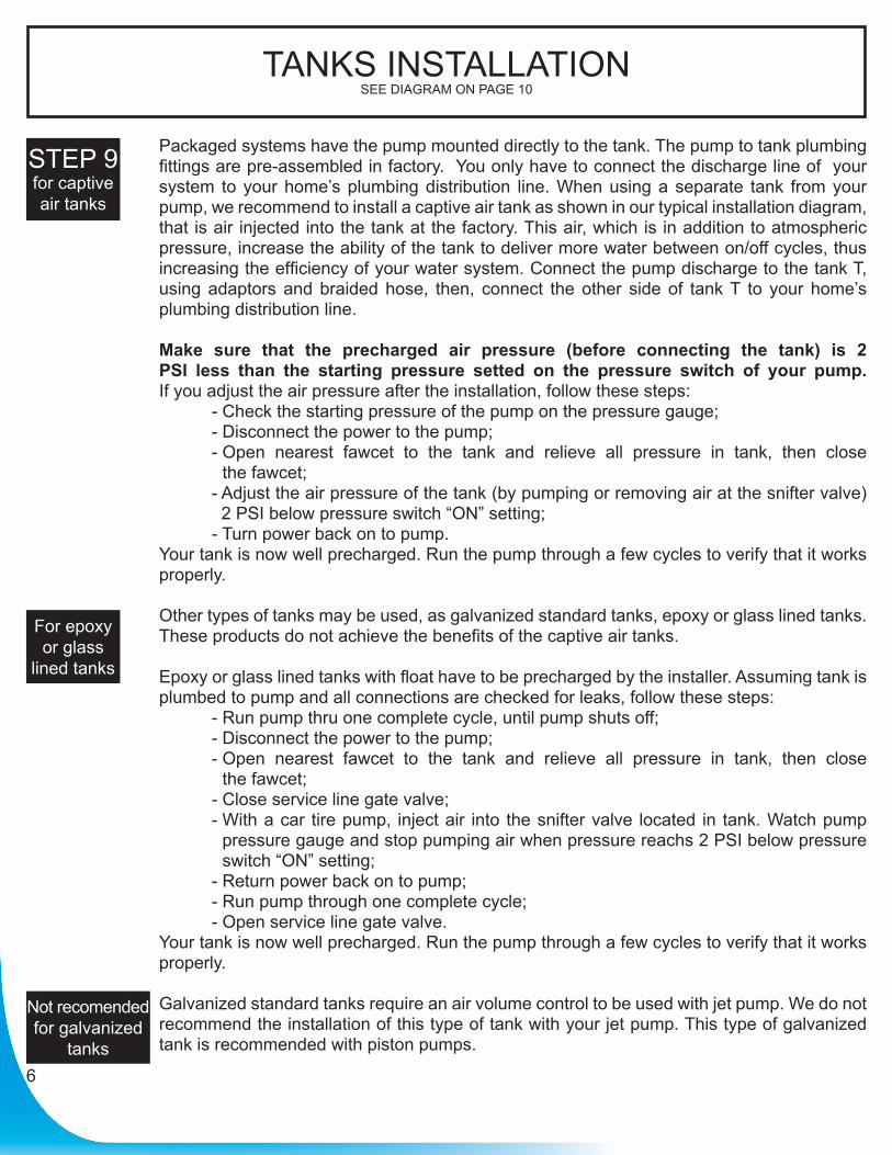
TANKS INSTALLATIONSEE DIAGRAM ON PAGE 10
Packaged systems have the pump mounted directly to the tank. The pump to tank plumbing fittings are pre-assembled in factory. You only have to connect the discharge line of your system to your home’s plumbing distribution line. When using a separate tank from your pump, we recommend to install a captive air tank as shown in our typical installation diagram, that is air injected into the tank at the factory. This air, which is in addition to atmospheric pressure, increase the ability of the tank to deliver more water between on/off cycles, thus increasing the efficiency of your water system. Connect the pump discharge to the tank T, using adaptors and braided hose, then, connect the other side of tank T to your home’s plumbing distribution line.
Make sure that the precharged air pressure (before connecting the tank) is 2 PSI less than the starting pressure setted on the pressure switch of your pump. If you adjust the air pressure after the installation, follow these steps: - Check the starting pressure of the pump on the pressure gauge; - Disconnect the power to the pump; - Open nearest fawcet to the tank and relieve all pressure in tank, then close
the fawcet; - Adjust the air pressure of the tank (by pumping or removing air at the snifter valve)
2 PSI below pressure switch “ON” setting; - Turn power back on to pump.Your tank is now well precharged. Run the pump through a few cycles to verify that it works properly.
Other types of tanks may be used, as galvanized standard tanks, epoxy or glass lined tanks. These products do not achieve the benefits of the captive air tanks.
Epoxy or glass lined tanks with float have to be precharged by the installer. Assuming tank is plumbed to pump and all connections are checked for leaks, follow these steps: - Run pump thru one complete cycle, until pump shuts off; - Disconnect the power to the pump; - Open nearest fawcet to the tank and relieve all pressure in tank, then close
the fawcet; - Close service line gate valve; - With a car tire pump, inject air into the snifter valve located in tank. Watch pump
pressure gauge and stop pumping air when pressure reachs 2 PSI below pressure switch “ON” setting;
- Return power back on to pump; - Run pump through one complete cycle; - Open service line gate valve.Your tank is now well precharged. Run the pump through a few cycles to verify that it works properly.
Galvanized standard tanks require an air volume control to be used with jet pump. We do not recommend the installation of this type of tank with your jet pump. This type of galvanized tank is recommended with piston pumps.
STEP 9for captiveair tanks
For epoxy or glass
lined tanks
Not recomended for galvanized
tanks6
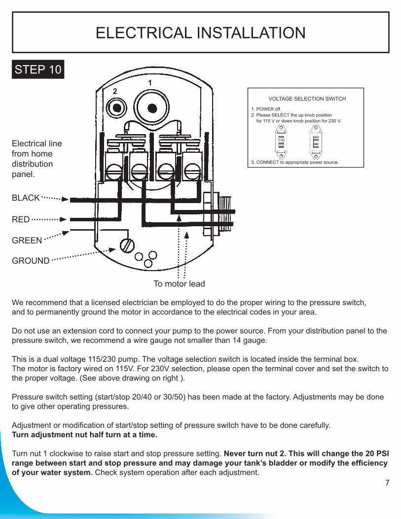
ELECTRICAL INSTALLATION
STEP 10
7
Electrical linefrom home distribution panel.
BLACK
RED
GREEN
GROUND
To motor lead
We recommend that a licensed electrician be employed to do the proper wiring to the pressure switch, and to permanently ground the motor in accordance to the electrical codes in your area.
Do not use an extension cord to connect your pump to the power source. From your distribution panel to the pressure switch, we recommend a wire gauge not smaller than 14 gauge.
This is a dual voltage 115/230 pump. The voltage selection switch is located inside the terminal box. The motor is factory wired on 115V. For 230V selection, please open the terminal cover and set the switch to the proper voltage. (See above drawing on right ).
Pressure switch setting (start/stop 20/40 or 30/50) has been made at the factory. Adjustments may be done to give other operating pressures.
Adjustment or modification of start/stop setting of pressure switch have to be done carefully. Turn adjustment nut half turn at a time.
Turn nut 1 clockwise to raise start and stop pressure setting. Never turn nut 2. This will change the 20 PSI range between start and stop pressure and may damage your tank’s bladder or modify the efficiency of your water system. Check system operation after each adjustment.
12
VOLTAGE SELECTION SWITCH
1. POWER off.2. Please SELECT the up knob position
for 115 V or down knob position for 230 V.
3. CONNECT to appropriate power source.
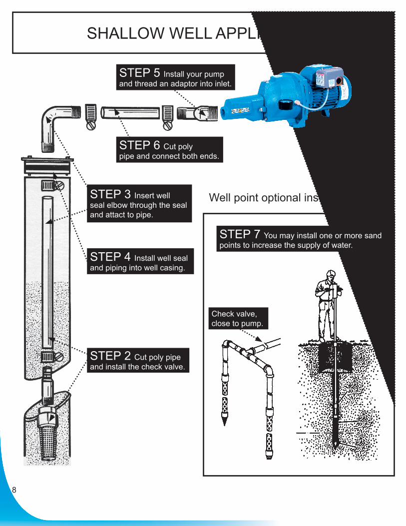
SHALLOW WELL APPLICATION
Well point optional installation
8
STEP 6 Cut polypipe and connect both ends.
STEP 4 Install well sealand piping into well casing.
STEP 2 Cut poly pipeand install the check valve.
Check valve,close to pump.
STEP 3 Insert wellseal elbow through the seal and attact to pipe.
STEP 7 You may install one or more sandpoints to increase the supply of water.
STEP 5 Install your pumpand thread an adaptor into inlet.
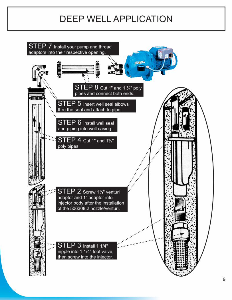
DEEP WELL APPLICATION
9
STEP 3 Install 1 1/4" nipple into 1 1/4" foot valve, then screw into the injector.
STEP 6 Install well seal and piping into well casing.
STEP 8 Cut 1" and 1 ¼" poly pipes and connect both ends.
STEP 2 Screw 1¼" venturi adaptor and 1" adaptor into injector body after the installation of the 506308.2 nozzle/venturi.
STEP 4 Cut 1" and 1¼" poly pipes.
STEP 5 Insert well seal elbows thru the seal and attach to pipe.
STEP 7 Install your pump and thread adaptors into their respective opening.
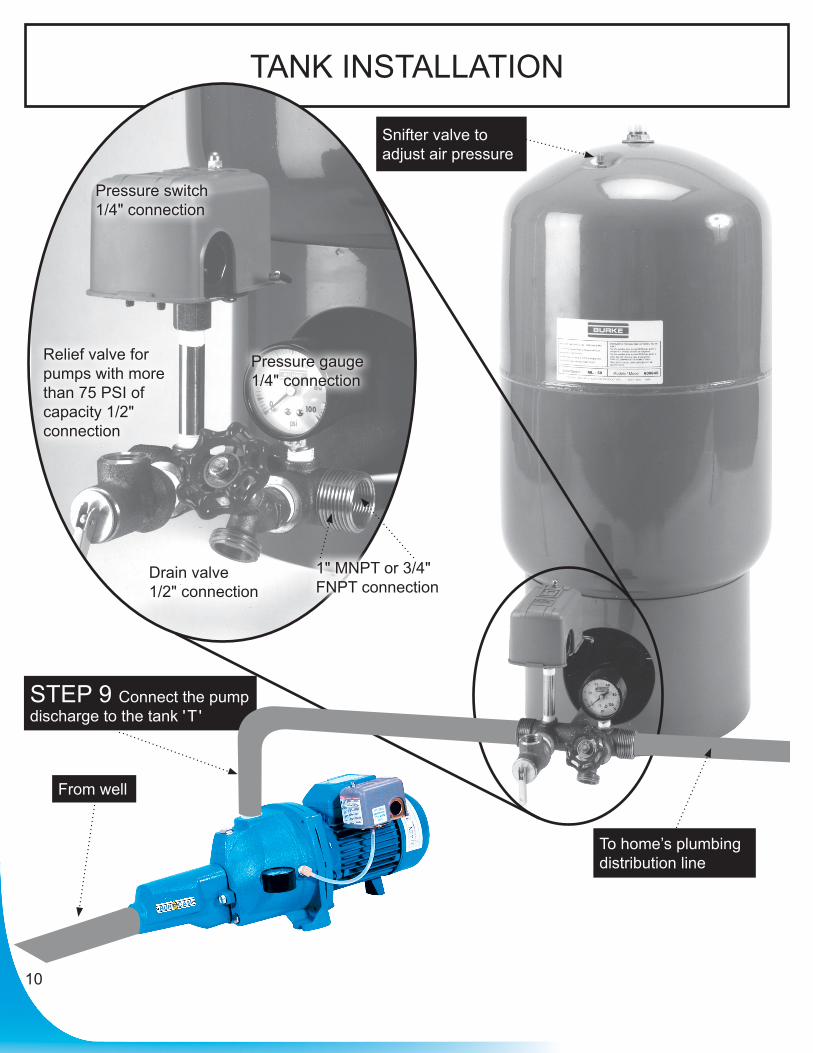
TANK INSTALLATION
10
STEP 9 Connect the pump discharge to the tank ' T '
Snifter valve to adjust air pressure
To home’s plumbing distribution line
Pressure switch1/4" connection
Pressure gauge1/4" connection
Drain valve1/2" connection
1" MNPT or 3/4" FNPT connection
Relief valve for pumps with more than 75 PSI of capacity 1/2" connection
From well

Repair parts may be ordered from your autorized point of sale or from
BUR-CAM PUMPS
11
Ref Pieces Descriptions 1 506014OS Junction cover box 1 506014 Junction cover box 2 506015 Motor capacitor 3 506065OS Capacitor junction box 3 506065 Capacitor junction box 4 506030GP Stator 1/2HP 4 506285 Stator 3/4HP 5 506297 Pump body cap screw 6 506307 Injector gasket 7 506299 Drain plug 8 506315 Drain plug washer 9 506022 Impeller nut10 506294P Impeller 1/2HP10 506292P Impeller 3/4HP11 506411 Seal snap ring12 506026 Sand slinger13 506415 Injector body screws (4)14 506289 Pump bracket15 506287 Seal plate16 506288 Pump body ‘‘O’’ ring17 506309 Mechanical seal
Ref Pieces Descriptions18 506317 Diffuser19 506298 Diffuser ‘‘O’’ ring20 506300 Priming plug21 506400 Priming plug washer22 506286 C.I. pump body23 506308.1 ‘‘O’’ ring, nozzle and venturi for shallow well23 506308.2 ‘‘O’’ ring, nozzle and venturi DW for deep well24 506306.1 Injector body (only)25 506312 Motor foot26 506031 Pump side motor bearing27 506314GP Rotor 1/2HP27 506284 Rotor 3/4HP28 506032 Fan side motor bearing29 506296 Motor end bell30 506017 Motor fan31 506016 Fan cover32 506094 115/230V selector33 506430 Screws (3)34 506318 Impeller shaft key35 506419 Cover bolt
REPAIR PARTS
1
19
7
25
31
4
22
10
28 16
342
20
8
26
14
32
13
5
23
11
29
17
35
3
21
9
27
15
33
6
24
12
30
18
506721G 2015 506321G 2015
12
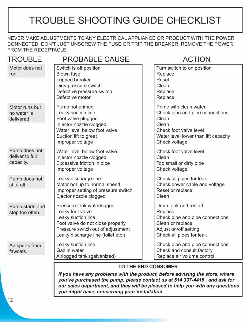
TROUBLE SHOOTING GUIDE CHECKLISTNEVER MAKE ADJUSTMENTS TO ANY ELECTRICAL APPLIANCE OR PRODUCT WITH THE POWER CONNECTED. DON’T JUST UNSCREW THE FUSE OR TRIP THE BREAKER, REMOVE THE POWER FROM THE RECEPTACLE.
TROUBLE PROBABLE CAUSE ACTIONSwitch is off positionBlown fuseTripped breakerDirty pressure switchDefective pressure switchDefective motor
Pump not primedLeaky suction lineFoot valve pluggedInjector nozzle cloggedWater level below foot valveSuction lift to greatImproper voltage
Water level below foot valveInjector nozzle cloggedExcessive friction in pipeImproper voltage
Leaky discharge lineMotor not up to normal speedImproper setting of pressure switchEjector nozzle clogged
Pressure tank waterloggedLeaky foot valveLeaky suction lineFoot valve do not close properlyPressure switch out of adjustmentLeaky discharge line (toilet etc.)
Leaky suction lineGaz in waterAirlogged tank (galvanized)
Turn switch to on positionReplaceResetCleanReplaceReplace
Prime with clean waterCheck pipe and pipe connectionsCleanCleanCheck foot valve levelWater level lower than lift capacityCheck voltage
Check foot valve levelCleanToo small or dirty pipeCheck voltage
Check all pipes for leakCheck power cable and voltageReset or replaceClean
Drain tank and restartReplaceCheck pipe and pipe connectionsClean or replaceAdjust on/off settingCheck all pipes for leak
Check pipe and pipe connectionsCheck and consult factoryReplace air volume control
Motor does not run.
Motor runs but no water is delivered.
Pump does not deliver to full capacity.
Pump does not shut off.
Pump starts and stop too often.
Air spurts from fawcets.
TO THE END CONSUMERIf you have any problems with the product, before advising the store, where you’ve purchased the pump, please contact us at 514 337-4415 , and ask for our sales department, and they will be pleased to help you with any questions you might have, concerning your installation.