Embed Size (px)
Citation preview

ULTRA LX
JET SKI® WatercraftService Manual

is a trademark of Kawasaki Heavy Industries, Ltd. registered in U.S.A., Japan,Austria, Benelux, Sweden, Denmark, Switzerland, France, Canada, Finland, Norway, Greece, Italy,U.K., Portugal, Thailand, and Taiwan.
KAWASAKI JET SKI® is a trademark of Kawasaki Heavy Industries, Ltd. registered in Australia.

This quick reference guide will assistyou in locating a desired topic or pro-cedure.•Bend the pages back to match theblack tab of the desired chapter num-ber with the black tab on the edge ateach table of contents page.•Refer to the sectional table of contentsfor the exact pages to locate the spe-cific topic required.
Quick Reference Guide
General Information 1 jPeriodic Maintenance 2 jFuel System (DFI) 3 jEngine Lubrication System 4 jExhaust System 5 jEngine Top End 6 jEngine Removal/Installation 7 jEngine Bottom End 8 jCooling and Bilge Systems 9 jDrive System 10 jPump and Impeller 11 jSteering 12 jHull/Engine Hood 13 jElectrical System 14 jStorage 15 jAppendix 16 j


ULTRA LX
JET SKI® WatercraftService Manual
All rights reserved. No parts of this publication may be reproduced, stored in a retrieval system, ortransmitted in any form or by any means, electronic mechanical photocopying, recording or otherwise,without the prior written permission of Quality Assurance Division/Consumer Products and MachineryCompany/Kawasaki Heavy Industries, Ltd., Japan.No liability can be accepted for any inaccuracies or omissions in this publication, although every possible
care has been taken to make it as complete and accurate as possible.The right is reserved to make changes at any time without prior notice and without incurring an obligation
to make such changes to products manufactured previously. See your JET SKI® watercraft dealer for thelatest information on product improvements incorporated after this publication.All information contained in this publication is based on the latest product information available at the time
of publication. Illustrations and photographs in this publication are intended for reference use only and maynot depict actual model component parts.
© 2006 Kawasaki Heavy Industries, Ltd. Second Edition (1):Sep. 11, 2007 (K)

LIST OF ABBREVIATIONSA ampere(s) lb pound(s)ABDC after bottom dead center m meter(s)AC alternating current min minute(s)ATDC after top dead center N newton(s)BBDC before bottom dead center Pa pascal(s)BDC bottom dead center PS horsepowerBTDC before top dead center psi pound(s) per square inch°C degree(s) Celsius r revolutionDC direct current rpm revolution(s) perminuteF farad(s) TDC top dead center°F degree(s) Fahrenheit TIR total indicator readingft foot, feet V volt(s)g gram(s) W watt(s)h hour(s) Ω ohm(s)L liter(s)
COUNTRY AND AREA CODESAT Austria DE GermanyCA Canada GB United KingdomCAL California US United StatesCH Switzerland WVTA Whole Vehicle Type Approval

MAINTENANCE AND ADJUSTMENTS
Maintenance, replacement, or repair of the emission control devices and systems maybe performed by any marine Sl engine repair establishment or individual.
EMISSION CONTROL INFORMATION
Fuel InformationTHIS ENGINE IS CERTIFIED TO OPERATE ON UNLEADED REGULARGRADE GASOLINE
ONLY.Aminimum of 87 octane of the antiknock index is recommended. The antiknock index is posted
on service station pumps.
Emission Control InformationTo protect the environment in which we all live, Kawasaki has incorporated an exhaust emis-
sion control system in compliance with applicable regulations of the United States EnvironmentalProtection Agency.
Exhaust Emission Control SystemThis system reduces the amount of pollutants discharged into the atmosphere by the exhaust
of this engine. The fuel, ignition and exhaust systems of this engine have been carefully de-signed and constructed to ensure an efficient engine with low exhaust pollutant levels.
MaintenanceProper maintenance and repair are necessary to ensure that watercraft will continue to have
low emission levels. This Service Manual contains those maintenance and repair recommenda-tions for this engine. Those items identified by the Periodic Maintenance Chart are necessaryto ensure compliance with the applicable standards.
Tampering with Emission Control System ProhibitedFederal law prohibits the following acts or the causing thereof: (1) the removal or rendering
inoperative by any person other than for purposes of maintenance, repair, or replacement, ofany device or element of design incorporated into any new engine for the purposes of emissioncontrol prior to its sale or delivery to the ultimate purchaser or while it is in use, or (2) the useof the engine after such device or element of design has been removed or rendered inoperativeby any person.
Among those acts presumed to constitute tampering are the acts listed below:
Do not tamper with the original emission related parts.* Digital Transistor Ignition System* Fuel Pump* Spark Plugs* Throttle Body and Internal Parts* Fuel Injectors* ECU

Foreword
This manual is designed primarily for use bytrained mechanics in a properly equipped shop.However, it contains enough detail and basic in-formation to make it useful to the owner who de-sires to perform his own basic maintenance andrepair work. A basic knowledge of mechanics,the proper use of tools, and workshop proce-dures must be understood in order to carry outmaintenance and repair satisfactorily. When-ever the owner has insufficient experience ordoubts his ability to do the work, all adjust-ments, maintenance, and repair should be car-ried out only by qualified mechanics.In order to perform the work efficiently and
to avoid costly mistakes, read the text, thor-oughly familiarize yourself with the proceduresbefore starting work, and then do the work care-fully in a clean area. Whenever special tools orequipment are specified, do not use makeshifttools or equipment. Precision measurementscan only be made if the proper instruments areused, and the use of substitute tools may ad-versely affect safe operation.For the duration of the warranty period,
we recommend that all repairs and scheduledmaintenance be performed in accordance withthis service manual. Any owner maintenance orrepair procedure not performed in accordancewith this manual may void the warranty.To get the longest life out of your JET SKI®
watercraft:• Follow the Periodic Maintenance Chart in theService Manual.• Be alert for problems and non-scheduledmaintenance.• Use proper tools and genuine Kawasaki JETSKI® watercraft parts. Special tools, gauges,and testers that are necessary when servic-ing Kawasaki JET SKI® watercraft are intro-duced by the Service Manual. Genuine partsprovided as spare parts are listed in the PartsCatalog.
• Follow the procedures in this manual care-fully. Don’t take shortcuts.•Remember to keep complete records of main-tenance and repair with dates and any newparts installed.
How to Use This ManualIn this manual, the product is divided into
its major systems and these systems make upthe manual’s chapters. The Quick ReferenceGuide shows you all of the product’s systemand assists in locating their chapters. Eachchapter in turn has its own comprehensive Ta-ble of Contents.For example, if you want ignition coil informa-
tion, use the Quick Reference Guide to locatethe Electrical System chapter. Then, use theTable of Contents on the first page of the chap-ter to find the Ignition Coil section.Whenever you see these WARNING and
CAUTION symbols, heed their instructions!Always follow safe operating and maintenancepractices.
WARNINGThis warning symbol identifies specialinstructions or procedures which, if notcorrectly followed, could result in per-sonal injury, or loss of life.
CAUTIONThis caution symbol identifies specialinstructions or procedures which, if notstrictly observed, could result in dam-age to or destruction of equipment.
This manual contains four more symbols (inaddition toWARNING andCAUTION) which willhelp you distinguish different types of informa-tion.

NOTEThis note symbol indicates points of par-ticular interest for more efficient and con-venient operation.
• Indicates a procedural step or work to bedone.Indicates a procedural sub-step or how to dothe work of the procedural step it follows. Italso precedes the text of a NOTE.Indicates a conditional step or what action totake based on the results of the test or inspec-tion in the procedural step or sub-step it fol-lows.
In most chapters an exploded view illustrationof the system components follows the Table ofContents. In these illustrations you will find theinstructions indicating which parts require spec-ified tightening torque, oil, grease or a lockingagent during assembly.
This model, JT1500C, is mounted with a four-stroke engine.When the JET SKI® watercraft is submerged
and swamped, the four-stroke engine needsspecial care and systematic procedure for re-covery compared with the two-stroke engine.Therefore in this manual, such procedures,which are not shown in SMs for two-strokeengines, are explained thoroughly to cope withthe cases.Refer to the section, After submerging in
Chapter 9, Cooling and Bilge Systems for thesummary and detailed procedures.


GENERAL INFORMATION 1-1
1
General InformationTable of Contents
Before Servicing ..................................................................................................................... 1-2Model Identification................................................................................................................. 1-10General Specifications............................................................................................................ 1-11Unit Conversion Table ............................................................................................................ 1-13

1-2 GENERAL INFORMATIONBefore Servicing
Before starting to perform an inspection service or carry out a disassembly and reassembly oper-ation on watercraft, read the precautions given below. To facilitate actual operations, notes, illustra-tions, photographs, cautions, and detailed descriptions have been included in each chapter wherevernecessary. This section explains the items that require particular attention during the removal andreinstallation or disassembly and reassembly of general parts.Especially note the following:
Kawasaki Diagnostic System (KDS) SoftwareKDS software that runs on Windows personal computer (PC) will be available as a diagnostic tool
for watercraft with Kawasaki DFI system.You need the following items to use the KDS.
Item P/No.KDS Software Version 2. (CD-ROM, Updated Version) 57001-1503Signal Converter 57001-1504Communication Cable and Cable Adapter 57001-1470KDS Adapter Cable 57001-1696
The connectors for the communication cable and KDS adapter cable are located in the front.Connect the communication cable to the KDS connector (4-pin) [A] and the KDS adapter cablebetween the ignition switch (immobilizer amplifier) lead connectors (6-pin) [B].
AdjustmentsAdjustments shall be made in accordance with the Periodic Maintenance Chart or whenever trou-
bleshooting or presence of symptoms indicate that adjustments may be required. Whenever runningof the engine is required during maintenance it is best to have the watercraft in water.
CAUTIONDo not run the engine without cooling water supply for more than 15 seconds, especiallyin high revolutionary speed or severe engine and exhaust system damage will occur.
Auxiliary CoolingAn auxiliary cooling supply may be used if the watercraft cannot be operated in water during adjust-
ments. If possible, always operate the watercraft in water rather than use an auxiliary cooling supply.

GENERAL INFORMATION 1-3Before Servicing
•Obtain a standard garden hose [A] and a garden hoseadapter [B] as shown.C: Garden Hose Fitting of AdapterD: Flushing Fitting of AdapterE: Thread: Rp 3/4
Optional part (P/No. 92005-3746) is available as a gardenhose adapter.
•Open the front storage compartment cover.• Remove the flushing cap [A] on the brim of the storagecompartment.
• Screw a garden hose adapter [A] onto the flushing fitting[B].• Attach a garden hose [C] to a garden hose adapter andsecure the hose clamp [D].
• Attach the garden hose to a faucet. Do not turn on the water until the engine is running and turn itoff immediately when the engine stops. The engine requires 2.4 L/min (2.5 qts/min) at 1 800 rpmand 7.0 L/min (7.4 qts/min) at 6 000 rpm.
CAUTIONInsufficient cooling supply will cause the engine and/or exhaust system to overheat andsevere damagewill occur. Excessive cooling supplymay kill the engine and flood the cylin-ders, causing hydraulic lock. Hydraulic lock will cause severe damage to the engine. If theengine dies while using an auxiliary cooling supply, the water must be shut off immediately.
CAUTIONAlways turn the boat on its left side. Rolling to the right side can cause water in the exhaustsystem to run into the engine, with possible engine damage.
1-4 GENERAL INFORMATIONBefore Servicing
CAUTIONTurn the capsized boat clockwise so that the port side always faces downward. Turningcounterclockwise can cause water in the exhaust system to run into the engine, with pos-sible engine damage.
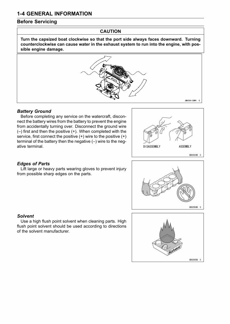
Battery GroundBefore completing any service on the watercraft, discon-
nect the battery wires from the battery to prevent the enginefrom accidentally turning over. Disconnect the ground wire(–) first and then the positive (+). When completed with theservice, first connect the positive (+) wire to the positive (+)terminal of the battery then the negative (–) wire to the neg-ative terminal.
Edges of PartsLift large or heavy parts wearing gloves to prevent injury
from possible sharp edges on the parts.
SolventUse a high flush point solvent when cleaning parts. High
flush point solvent should be used according to directionsof the solvent manufacturer.

GENERAL INFORMATION 1-5Before Servicing
Cleaning Watercraft before DisassemblyClean the watercraft thoroughly before disassembly. Dirt
or other foreign materials entering into sealed areas duringwatercraft disassembly can cause excessive wear and de-crease performance of the watercraft.
Arrangement and Cleaning of Removed PartsDisassembled parts are easy to confuse. Arrange the
parts according to the order the parts were disassembledand clean the parts in order prior to assembly.
Storage of Removed PartsAfter all the parts including subassembly parts have been
cleaned, store the parts in a clean area. Put a clean clothor plastic sheet over the parts to protect from any foreignmaterials that may collect before re-assembly.
InspectionReuse of worn or damaged parts may lead to serious ac-
cident. Visually inspect removed parts for corrosion, discol-oration, or other damage. Refer to the appropriate sectionsof this manual for service limits on individual parts. Replacethe parts if any damage has been found or if the part is be-yond its service limit.
Replacement PartsReplacement Parts must be KAWASAKI genuine or
recommended by KAWASAKI. Gaskets, O-rings, Oil seals,Grease seals, circlips or cotter pins must be replaced withnew ones whenever disassembled.

1-6 GENERAL INFORMATIONBefore Servicing
Assembly OrderIn most cases assembly order is the reverse of disassem-
bly, however, if assembly order is provided in this ServiceManual, follow the procedures given.
Tightening SequenceGenerally, when installing a part with several bolts, nuts,
or screws, start them all in their holes and tighten them toa snug fit. Then tighten them according to the specified se-quence to prevent case warpage or deformation which canlead to malfunction. Conversely when loosening the bolts,nuts, or screws, first loosen all of them by about a quar-ter turn and then remove them. If the specified tighteningsequence is not indicated, tighten the fasteners alternatingdiagonally.
Tightening TorqueIncorrect torque applied to a bolt, nut, or screw may
lead to serious damage. Tighten fasteners to the specifiedtorque using a good quality torque wrench.
ForceUse common sense during disassembly and assembly,
excessive force can cause expensive or hard to repair dam-age. When necessary, remove screws that have a non-permanent locking agent applied using an impact driver.Use a plastic-faced mallet whenever tapping is necessary.
Gasket, O-ringHardening, shrinkage, or damage of both gaskets
and O-rings after disassembly can reduce sealing per-formance. Remove old gaskets and clean the sealingsurfaces thoroughly so that no gasket material or othermaterial remains. Install new gaskets and replace usedO-rings when re-assembling
GENERAL INFORMATION 1-7Before Servicing
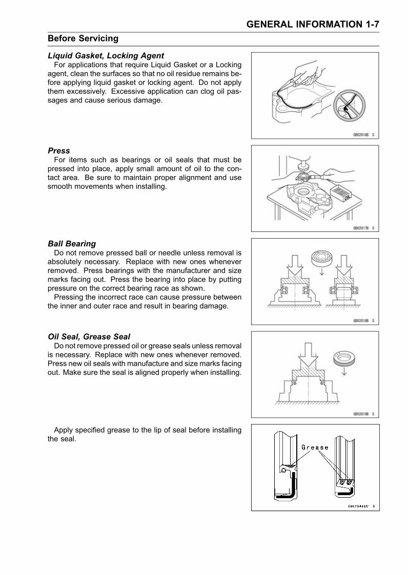
Liquid Gasket, Locking AgentFor applications that require Liquid Gasket or a Locking
agent, clean the surfaces so that no oil residue remains be-fore applying liquid gasket or locking agent. Do not applythem excessively. Excessive application can clog oil pas-sages and cause serious damage.
PressFor items such as bearings or oil seals that must be
pressed into place, apply small amount of oil to the con-tact area. Be sure to maintain proper alignment and usesmooth movements when installing.
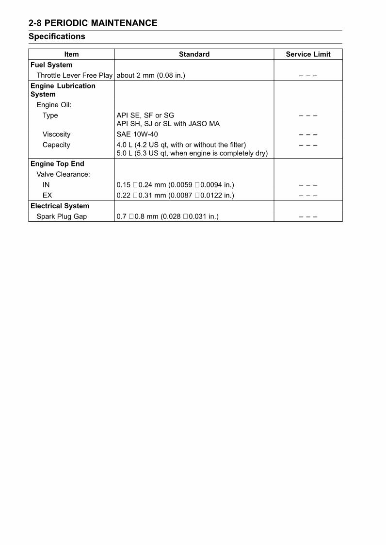
Ball BearingDo not remove pressed ball or needle unless removal is
absolutely necessary. Replace with new ones wheneverremoved. Press bearings with the manufacturer and sizemarks facing out. Press the bearing into place by puttingpressure on the correct bearing race as shown.Pressing the incorrect race can cause pressure between
the inner and outer race and result in bearing damage.
Oil Seal, Grease SealDo not remove pressed oil or grease seals unless removal
is necessary. Replace with new ones whenever removed.Press new oil seals with manufacture and size marks facingout. Make sure the seal is aligned properly when installing.
Apply specified grease to the lip of seal before installingthe seal.

1-8 GENERAL INFORMATIONBefore Servicing
Circlips, Cotter PinsReplace circlips or cotter pins that were removed with new
ones. Take care not to open the clip excessively when in-stalling to prevent deformation.
LubricationIt is important to lubricate rotating or sliding parts during
assembly to minimize wear during initial operation. Lubri-cation points are called out throughout this manual, applythe specific oil or grease as specified.
Direction of Engine RotationWhen rotating the crankshaft, by hand, the free play
amount of rotating direction will affect the adjustment. Ro-tate the crankshaft to positive direction (counter-clockwiseviewed from stern sinde).
Electrical WiresA two-color wire is identified first by the primary color and
then the stripe color. Unless instructed otherwise, electricalwires must be connected to those of the same color.
InstrumentUse a meter that has enough accuracy for an accurate
measurement. Read the manufacture’s instructions thor-oughly before using the meter. Incorrect values may leadto improper adjustments.

GENERAL INFORMATION 1-9Before Servicing
Harness ConnectorApply grease [A] on all connectors of harness [B] for water
resistance. Do not apply grease on the only connector ofinlet air pressure sensor.

1-10 GENERAL INFORMATIONModel Identification
JT1500C7F Left Side View
JT1500C7F Right Side View
Hull Identification Number (HIN) Engine Number

GENERAL INFORMATION 1-11General Specifications
Items JT1500C7F ∼EngineType 4-stroke, DOHC, 4-cylinder, water cooledDisplacement 1 498 cm³ (91.4 cu in.)Bore and Stroke 83 × 69.2 mm (3.27 × 2.72 in.)Compression Ratio 10.6 : 1Maximum Horsepower 118 kW (160 PS) @7 500 r/min (rpm)Maximum Torque 152 N·m (15.5 kgf·m, 112.1 ft·lb) @7 250 r/min (rpm)Ignition System Digital transistorLubrication System Forced lubrication (semi-dry sump)Carburetion System FI (fuel injection) MIKUNI AC 60 × 1Starting System Electric starterCylinder Numbering Method Front (bow) to rear (stern), 1-2-3-4Firing Order 1-2-4-3Valve Timing:Inlet:Open 22.5° BTDCClose 67.5° ABDCDuration 270°
Exhaust:Open 74.5° BBDCClose 9.5° ATDCDuration 264°
Tuning SpecificationsSpark plug:Type NGK CR9EKGap 0.7 ∼ 0.8 mm (0.028 ∼ 0.031 in.)
Ignition Timing 3° ATDC @1 300 r/min ∼ 32° BTDC @3 000 r/min (rpm)Idle Speed 1 300 ±100 r/min (rpm) -in water
1 300 ±100 r/min (rpm) -out of waterCompression Pressure 1 190 ∼ 1 799 kPa (12.1 ∼ 18.3 kgf/cm², 173 ∼ 261 psi) @430
r/min (rpm)Drive SystemCoupling Direct drive from engineJet Pump:Type Axial flow single stageThrust 4 250 N (434 kgf, 955 lb)
Steering Steerable nozzleBraking Water drag
Performance†Minimum Turning Radius 4.0 m (13.1 ft)†Fuel Consumption 43 L/h (11.4 US gal/h) @full throttle†Cruising Range 146 km (90.7 mile) @full throttle 1 hour and 43 minutes (3 person)
DimensionsOverall Length 3 370 mm (132.7 in.)

1-12 GENERAL INFORMATIONGeneral Specifications
Items JT1500C7F ∼Overall Width 1 195 mm (47.0 in.)Overall Height 1 150 mm (45.3 in.)Dry Weight 380 kg (838 lb)Air Draft (1) 849 mm (33.4 in.)Maximum Draft (2) 368 mm (14.5 in.)Fuel Tank Capacity 78 L (20.6 US gal)
Engine OilType API SE, SF or SG
API SH, SJ or SL with JASO MAViscosity SAE 10W-40Capacity 5.0 L (5.3 US qt)
Electrical EquipmentBattery 12 V 18 AhMaximum Generator Output 16 A @14 V†: This information shown here represents results under controlled conditions, and the informationmay not be correct under other conditions.
Specifications subject to change without notice, and may not apply to every country.(1) Vertical distance between the floating plane in the light craft condition and the highest point of
the craft structure, namely the handle top.(2) Draft in the fully loaded craft condition.*The information shown here represents results under controlled conditions, and the information
may not be correct under other condition.

GENERAL INFORMATION 1-13Unit Conversion Table
Prefixes for Units
Prefix Symbol Powermega M × 1 000 000kilo k × 1 000centi c × 0.01milli m × 0.001micro µ × 0.000001
Units of Masskg × 2.205 = lbg × 0.03527 = oz
Units of VolumeL × 0.2642 = gal (US)L × 0.2200 = gal (imp)L × 1.057 = qt (US)L × 0.8799 = qt (imp)L × 2.113 = pint (US)L × 1.816 = pint (imp)mL × 0.03381 = oz (US)mL × 0.02816 = oz (imp)mL × 0.06102 = cu in
Units of ForceN × 0.1020 = kgN × 0.2248 = lbkg × 9.807 = Nkg × 2.205 = lb
Units of Lengthkm × 0.6214 = milem × 3.281 = ftmm × 0.03937 = in.
Units of TorqueN·m × 0.1020 = kgf·mN·m × 0.7376 = ft·lbN·m × 8.851 = in·lbkgf·m × 9.807 = N·mkgf·m × 7.233 = ft·lbkgf·m × 86.80 = in·lb
Units of PressurekPa × 0.01020 = kgf/cm²kPa × 0.1450 = psikPa × 0.7501 = cmHgkgf/cm² × 98.07 = kPakgf/cm² × 14.22 = psicmHg × 1.333 = kPa
Units of Speedkm/h × 0.6214 = mph
Units of PowerkW × 1.360 = PSkW × 1.341 = HPPS × 0.7355 = kWPS × 0.9863 = HP
Units of Temperature


PERIODIC MAINTENANCE 2-1
2
Periodic MaintenanceTable of Contents
Periodic Maintenance Chart ................................................................................................... 2-2Torque and Locking Agent...................................................................................................... 2-3Specifications ......................................................................................................................... 2-8Special Tools and Sealant ...................................................................................................... 2-9Periodic Maintenance Procedures.......................................................................................... 2-10Fuel System......................................................................................................................... 2-10Throttle Control System Inspection................................................................................... 2-10Air Filter Drain Caps Inspection and Cleaning .................................................................. 2-10Air Filter Inspection and Cleaning ..................................................................................... 2-11Fuel Vent Check Valve Inspection .................................................................................... 2-11Fuel Pump Screen Cleaning ............................................................................................. 2-12Throttle Shaft Spring Inspection........................................................................................ 2-12
Engine Lubrication System.................................................................................................. 2-12Engine Oil Change............................................................................................................ 2-12Oil Filter Replacement ...................................................................................................... 2-14
Engine Top End ................................................................................................................... 2-15Air Suction Valve Inspection ............................................................................................. 2-15Valve Clearance Inspection .............................................................................................. 2-15Engine Mounting Bolts Inspection and Tightness ............................................................. 2-20
Engine Bottom End.............................................................................................................. 2-20Coupling Damper Inspection............................................................................................. 2-20
Cooling and Bilge Systems.................................................................................................. 2-20Cooling System Flushing .................................................................................................. 2-20Bilge System Flushing ...................................................................................................... 2-22
Pump and Impeller............................................................................................................... 2-23Impeller Inspection............................................................................................................ 2-23
Steering ............................................................................................................................... 2-23Steering Cable/Shift Cable Inspection .............................................................................. 2-23Handlebar Pivot Lubrication.............................................................................................. 2-23
Hull/Engine Hood................................................................................................................. 2-24Drain Plug Inspection........................................................................................................ 2-24
Electrical System ................................................................................................................. 2-24Battery Charging Condition Inspection ............................................................................. 2-24Battery Terminals Inspection............................................................................................. 2-25Spark Plug Cleaning and Inspection................................................................................. 2-25
Lubrication ........................................................................................................................... 2-26All Hoses, Hose Clamps, Nuts, Bolts and Fasteners Check ............................................... 2-28Nuts, Bolts, and Fasteners Tightness Inspection.............................................................. 2-28Hose and Hose Connect Inspection ................................................................................. 2-28Rubber Strap Inspection ................................................................................................... 2-30

2-2 PERIODIC MAINTENANCEPeriodic Maintenance Chart
The scheduled maintenance must be done in accordance with this chart to keep the watercraft ingood running condition. The initial maintenance is vitally important and must not be neglected.
FrequencyDescription
Initial 10Hours
Every 25Hours
Every 50Hours
Every 100Hours
Refer-ence
Inspect throttle control system (e) • 2-10Inspect/clean air filter drain caps • 2-10
Inspect/clean air filter•
(or everyyear)
2-11
Inspect fuel vent check valve • 2-11Clean fuel pump screen (e) • 2-12Inspect throttle shaft spring (replacethrottle body if necessary) (e) • 2-12
Replace engine oil•
(or everyyear)
2-12
Replace engine oil filter • 2-14Check air suction valve • 2-15Inspect/adjust valve clearance (e) • 2-15
Inspect/tighten engine mounting bolts•
(or everyyear)
2-20
Inspect/replace coupling damper • 2-20Flush cooling system (after each use insalt water) • 2-20
Flush bilge line and filter • 2-22Inspect impeller blades for damage(remove) • 2-23
Inspect steering cable/shift cable • 2-23Lubricate handlebar pivot (disassemble) • 2-23Inspect hull drain screws (replace ifnecessary) • 2-24
Inspect battery charging condition • 2-24Inspect battery terminals • 2-25Clean and gap spark plugs (replace ifnecessary) (e) • 2-25
Lubricate throttle cable fitting at throttlebody • 2-26
Lubricate throttle cable and throttle fittingat throttle case • 2-26
Lubricate steering cable/shift cable balljoints and steering nozzle/reverse bucketpivots
• 2-26
Check all hoses, hose clamps, nuts,bolts, and fasteners • • 2-28
(e): Emission Related Items

PERIODIC MAINTENANCE 2-3Torque and Locking Agent
The following table list the tightening torque for the major fasteners, and the parts requiring use ofa non-permanent locking agent or silicone sealant.
Letters used in the “Remarks” column mean:EO: Apply oil to the threads and seating surface.L: Apply a non-permanent locking agent (Medium Strength: Loctite 242 Equivalent).LN: Apply a non-permanent locking agent (High Strength: Loctite 271 Equivalent).MO: Apply molybdenum disulfide grease oil solution.R: Replacement PartS: Tighten the fasteners following the specified sequence.SS: Apply silicone sealant to the threads.
TorqueFastener
N·m kgf·m ft·lbRemarks
Fuel SystemVehicle-down Sensor Mounting Screws 1.5 0.15 13 in·lbBracket Mounting Bolts 8.8 0.90 78 in·lb LInlet Manifold Mounting Bolts 25 2.5 18 LInlet Manifold Mounting Nuts 20 2.0 14Delivery Pipe Mounting Bolts 7.8 0.80 69 in·lbInlet Air Pressure Sensor Bolts 7.8 0.80 69 in·lbInlet Air Temperature Sensor 20 2.0 14Throttle Body Assy Mounting Bolts 20 2.0 14Inlet Manifold Drain Plug 20 2.0 14Inlet Manifold Plate Bolts 7.8 0.80 69 in·lbCrankshaft Sensor Screws 4.4 0.45 39 in·lb LCamshaft Position Sensor Bolt 7.8 0.80 69 in·lb LWater Temperature Sensor 15 1.5 11 see textOil Temperature Sensor 15 1.5 11 see textECU Mounting Bolts 3.0 0.3 27 in·lb LRelay Bolts 2.5 0.25 22 in·lb LThrottle Sensor Mounting Screws 2.0 0.20 18 in·lbISC Actuator Mounting Bolts 4.9 0.50 43 in·lbFuse Bracket Bolt 2.5 0.25 22 in·lb LFuel Filler Tube Clamp Screws 2.9 0.30 26 in·lbFuel Pump Holder Clamp Screws 2.9 0.30 26 in·lb LAir Filter Mounting Bolts 8.8 0.90 69 in·lb LAir Filter Bracket Mounting Bolts 7.8 0.80 69 in·lb LThrottle Cable Locknut 20 2.0 14 in·lbThrottle Case Mounting Screws 3.9 0.40 34 in·lbHarness Bolts 8.8 0.90 78 in·lb L
Engine Lubrication SystemBreather Plate Bolts 7.8 0.80 69 in·lbOil Filler Cap – – – Hand-tightenOil Passage Plugs 20 2.0 14 LOil Separator Tank Mounting Screws 4.9 0.50 43 in·lb LBreather Case Mounting Bolts 7.8 0.80 69 in·lbBreather Pipe Bolts 8.8 0.90 78 in·lb

2-4 PERIODIC MAINTENANCETorque and Locking Agent
TorqueFastener
N·m kgf·m ft·lbRemarks
Oil Passage Joints 11 1.1 95 in·lb LOil Cooler Assembly Bolts 7.8 0.80 69 in·lbOil Pressure Switch 15 1.5 11 SSOil Passage Bolt 78 8.0 58 SOil Filter 18 1.8 13 EOOil Cooler Positioning Bolt 20 2.0 14 SOil Pan Bolts 7.8 0.80 69 in·lb SDipstick Tube Bolts 7.8 0.80 69 in·lb L, SOil Pump Sprocket Bolt 16 1.6 12 LNOil Pump Cover Bolts 7.8 0.80 69 in·lbOil Pressure Relief Valve 15 1.5 11 LNOil Pipe Bolts 7.8 0.80 69 in·lbOil Pump Chain Guide Bolt 7.8 0.80 69 in·lbChain Guide Spring Plate Bolt 7.8 0.80 69 in·lb LOil Pump Body Plug 20 2.0 14Oil Pump Body Bolts 7.8 0.80 69 in·lbOil Screen Bolts 7.8 0.80 69 in·lb LWater Hose Joints 20 2.0 14
Exhaust SystemExhaust Manifold Mounting Nuts 25 2.5 18 SExhaust Manifold Mounting Bolts 25 2.5 18 L, SBypass Nozzle – – – LNFlushing Hose Joint 11 1.1 95 in·lb LWater Hose Joint 11 1.1 95 in·lb LWater Temperature Sensor 15 1.5 11 see chapter 3Exhaust Pipe Mounting Plate Bolts 29 3.0 22 LExhaust Pipe Mounting Bolts 29 3.0 22
Engine Top EndAir Suction Valve Cover Bolts 9.8 1.0 87 in·lbCylinder Head Cover Bolts 9.8 1.0 87 in·lbCamshaft Cap Bolts 12 1.2 104 in·lb SCylinder Head Bolts (M7) 20 2.0 14 SCylinder Head Bolts (M11) 23 2.3 17 First, MO, SCylinder Head Bolts (M11) 59 6.0 43 Final, MO, SWater Jacket Plugs 20 2.0 14 LCylinder Head Bolts (M6) 12 1.2 104 in·lb SEngine Hook Bolts 20 2.0 14Camshaft Position Sensor Bolt 9.8 1.0 87 in·lb LExhaust Side Camshaft Chain Guide Bolts(Upper) 25 2.5 18
Exhaust Side Camshaft Chain Guide Bolts(Lower) 12 1.2 104 in·lb
Upper Camshaft Chain Guide Bolts 12 1.2 104 in·lb S

PERIODIC MAINTENANCE 2-5Torque and Locking Agent
TorqueFastener
N·m kgf·m ft·lbRemarks
Inlet Side Camshaft Chain Guide Bolt 12 1.2 104 in·lb LCamshaft Chain Tensioner Mounting Bolts 9.8 1.0 87 in·lb LCamshaft Chain Tensioner Cap Bolt 20 2.0 14Camshaft Position Sensor Rotor Bolt 12 1.2 104 in·lb LWater Hose Joint 11 1.1 95 in·lb LOil Passage Joint 11 1.1 95 in·lb L
Engine Removal/InstallationEngine Mounting Bolts 36 3.7 27 LEngine Damper Mounting Bolts 16 1.6 12 L
Engine Bottom EndCrankshaft Sensor Cover Bolts 7.8 0.80 69 in·lbEngine Bracket Mounting Bolts 32 3.3 24 LTiming Rotor Bolt 20 2.0 14 LConnecting Rod Nuts – – – MO, see textOil Passage Plugs 20 2.0 14 LStator Mounting Bolts 12 1.2 104 in·lb LGrommet Cover Bolts 9.8 1.0 87 in·lb LMagneto Cover Bolts 20 2.0 14Output Cover Bolts 7.8 0.80 69 in·lbOutput Shaft 245 25.0 180 MOCoupling 110 11 81Crankcase Bolts (M10) 50 5.0 36 MO, SCrankcase Bolts (M8) 29 3.0 22 MO, SCrankcase Bolts (M8) 29 3.0 22 SCrankcase Bolts (M6) 12 1.2 104 in·lb S
Cooling and Bilge SystemsWater Hose Joint (L Shape Type) 11 1.1 95 in·lb SSWater Hose Joint (Straight Shape Type) 20 2.0 14 SSWater Hose Joint (Straight Shape Type) 11 1.1 95 in·lb SSCooling Hose Clamp Screws 2.5 0.25 22 in·lb
Drive SystemCoupling 39 4.0 29 LDrive Shaft Holder Mounting Bolts 22 2.2 16 LCoupling Cover Bolts 8.8 0.90 78 in·lb L
Pump and ImpellerPump Bracket Mounting Bolts (2) 19 1.9 14 LN, SSPump Bracket Mounting Bolts (4) 9.8 1.0 87 in·lb LPump Mounting Bolts 36 3.7 27 LGrate Mounting Bolts 9.8 1.0 87 in·lb LPump Cover Mounting Bolts 7.8 0.80 69 in·lb LImpeller 98 10 72Pump Cap Bolts 3.9 0.4 35 in·lb LPump Outlet Mounting Bolts 19 1.9 14 L

2-6 PERIODIC MAINTENANCETorque and Locking Agent
TorqueFastener
N·m kgf·m ft·lbRemarks
Steering Nozzle Pivot Bolts 19 1.9 14 LFilter Cover Mounting Bolts 9.8 1.0 87 in·lb LSteering Cable Joint Bolt 9.8 1.0 87 in·lb L
SteeringHandlebar Clamp Bolts 16 1.6 12 LAdjustable Steering Holder Nut 20 2.0 14.5Steering Neck Mounting Bolts 16 1.6 12 LSteering Shaft Locknut 49 ∼ 59 5.0 ∼ 6.0 36 ∼ 43Steering Holder Mounting Nuts 20 2.0 14.5 LThrottle Case Mounting Screws 3.9 0.40 35 in·lbStart/stop Switch Case Mounting Screws 3.9 0.40 35 in·lbShift Cable Nut 39 4.0 29Steering Cable Nut 39 4.0 29Steering Shaft Nut 2.9 0.30 26 in·lb see textSteering Cable Joint Bolt 9.8 1.0 87 in·lb LBall Joint 9.8 1.0 87 in·lb LShift Cable End Nut 9.8 1.0 87 in·lbReverse Bucket Pivot Bolts 19 1.9 14 L
Hull/Engine HoodHandrail Plate Nuts 9.8 1.0 87 in·lb LSide Cover Nuts – – – LFront Duct Bolts – – – LDamper Bracket Bolts – – – LSeat Lock Bolts – – – LFront Storage Compartment Cover Bolts – – – LSteering Cover Bolts – – – LMeter Screen Bolts – – – LNBracket Bolts 8.8 0.90 78 in·lb LReboarding Step Bolts – – – LHinge Shaft Nut 15.7 1.60 11.6Stabilizer Bolts 9.8 1.0 87 in·lb LNFront Bumper Bolts – – – LExhaust Outlet Bolts – – – L
Electrical SystemVehicle-down Sensor Mounting Screws 1.5 0.15 13 in·lbBracket Bolts 8.8 0.90 78 in·lb LStarter Relay Case Bolts 7.8 0.80 69 in·lbWater Temperature Sensor 15 1.5 11 see textStarter Relay Mounting Nuts 3.5 ∼ 4.5 0.35 ∼ 0.45 30 ∼ 40 in·lbStarter Cable Mounting Nuts 3.5 ∼ 4.5 0.35 ∼ 0.45 30 ∼ 40 in·lbOil Temperature Sensor 15 1.5 11 see textCamshaft Position Sensor Bolt 9.8 1.0 87 in·lb LRegulator/Rectifier Bolts 7.8 0.80 69 in·lb

PERIODIC MAINTENANCE 2-7Torque and Locking Agent
TorqueFastener
N·m kgf·m ft·lbRemarks
Relay Bolts 2.5 0.25 22 in·lb LECU Mounting Bolts 3.0 0.30 27 in·lb LFuse Bracket Bolt 2.5 0.25 22 in·lb LMultifunction Meter Mounting Bolts 3.9 0.40 35 in·lbStart/stop Switch Case Mounting Screw 3.9 0.40 35 in·lbSpeed Sensor Mounting Bolts 3.9 0.40 35 in·lb LStarter Motor Through Bolts 6.4 0.65 56 in·lb L, RStarter Motor Mounting Bolts 8.8 0.90 78 in·lb LStarter Motor Ground Bolt 8.8 0.90 78 in·lbStarter Motor Terminal Nut 8.8 0.90 78 in·lbStator Coil Bolts 12 1.2 104 in·lb LGrommet Holder Bolts 8.8 0.90 78 in·lb LIgnition Coil Mounting Bolts 8.8 0.90 78 in·lb LTiming Rotor Bolt 20 2.0 14 LCrankshaft Sensor Screws 4.4 0.45 39 in·lb LRubber Grommet Holder Screws 4.4 0.45 39 in·lb LCrankshaft Sensor Cover Bolts 7.8 0.80 69 in·lbSpark Plugs 13 1.3 113 in·lbThe next table, relating tightening torque to thread diameter, lists the basic torque for the bolts and
nuts. Use this table for only the bolts and nuts which do not require a specific torque value. All of thevalues are for use with dry solvent-cleaned threads.
General Fasteners (stainless bolt and nut)Torque
Threads dia. (mm)N·m kgf·m ft·lb
6 5.9 ∼ 8.8 0.60 ∼ 0.90 52 ∼ 78 in·lb8 16 ∼ 22 1.6 ∼ 2.2 12 ∼ 1610 30 ∼ 41 3.1 ∼ 4.2 22 ∼ 30
2-8 PERIODIC MAINTENANCESpecifications
Item Standard Service LimitFuel SystemThrottle Lever Free Play about 2 mm (0.08 in.) – – –
Engine LubricationSystemEngine Oil:Type API SE, SF or SG
API SH, SJ or SL with JASO MA– – –
Viscosity SAE 10W-40 – – –Capacity 4.0 L (4.2 US qt, with or without the filter)
5.0 L (5.3 US qt, when engine is completely dry)– – –
Engine Top EndValve Clearance:IN 0.15 ∼ 0.24 mm (0.0059 ∼ 0.0094 in.) – – –EX 0.22 ∼ 0.31 mm (0.0087 ∼ 0.0122 in.) – – –
Electrical SystemSpark Plug Gap 0.7 ∼ 0.8 mm (0.028 ∼ 0.031 in.) – – –
PERIODIC MAINTENANCE 2-9Special Tools and Sealant
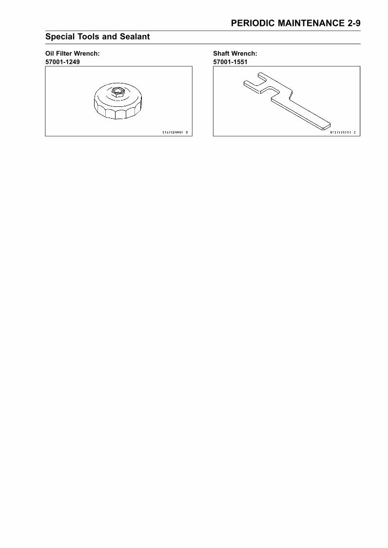
Oil Filter Wrench:57001-1249
Shaft Wrench:57001-1551

2-10 PERIODIC MAINTENANCEPeriodic Maintenance Procedures
Fuel SystemThrottle Control System Inspection• Inspect the throttle lever free play [A].If the free play is incorrect, adjust the throttle cable.
Throttle Lever Free PlayStandard: about 2 mm (0.08 in.)
•Check that the throttle lever moves smoothly from fullopen to close, and the throttle closes quickly and com-pletely in all steering positions by the return spring.If the throttle lever does not return properly, check thethrottle cable routing, cable adjustments, and cable dam-age. Then lubricate the throttle cable.• Run the engine at the idle speed, and turn the handlebarall the way to the right and left to ensure that the idle speeddoes not change.If the idle speed increase, check the throttle cable adjust-ment and the cable routing.
• Remove the seats (see Seat Removal in the Hull/EngineHood chapter).• Check throttle cable adjustment.•With the throttle lever released, the upper stop [A] on thethrottle pivot arm [B] should rest against the stopper [C]on the throttle body, and there should be slight slack inthe throttle cable.•When the throttle lever is fully applied (pulled), the lowerstop [D] on the pivot arm should be all the way up againstthe stopper on the throttle body.
If necessary, adjust the throttle cable.• Loosen and turn the locknuts [A] at the bracket until theupper stop on the pivot arm hits against the stopper onthe throttle body with slight cable slack.• Tighten the locknuts securely.Torque - Throttle Cable Locknuts: 7.8 N·m (0.80 kgf·m, 69
in·lb)
NOTEMake sure that the throttle pivot arm stops against thestopper on the throttle body with the throttle lever re-leased.
Air Filter Drain Caps Inspection and Cleaning•Remove the seats (see Seat Removal in the Hull/EngineHood chapter).• Inspect the air filter [A] for water inside with its drain caps[B].If there is water in the caps, remove both caps and dis-charge the water.
NOTEBe sure to have a rag or cloth underneath for possibleoily water.

PERIODIC MAINTENANCE 2-11Periodic Maintenance Procedures
Air Filter Inspection and Cleaning•Remove:Air Filter (see Air Filter Removal in the Fuel System (DFI)chapter)Flame Arrester [A] (see Air Filter Disassembly in the FuelSystem (DFI) chapter)
• Clean the flame arrester [A].• Visually inspect the flame arrester for damage.If necessary, replace it with a new one.
Fuel Vent Check Valve InspectionThe fuel vent check valve is mounted in the fuel tank vent
hose to prevent fuel from spilling during riding. Air can flowinto the tank to allow fuel to be drawn out by the fuel pump,but fuel cannot flow out the check valve.
• Remove the seats (see Seat Removal in the Hull/EngineHood chapter).• Cut off the bands [A].• Pull out each end of the fuel vent check valve [B] from thevent hoses [C].
• Blow through the fuel vent check valve from each end.If the check valve will allow air to flow as shown, it is OK.If air will flow through the check valve in both direction orin neither direction, the check valve must be replaced.
2-12 PERIODIC MAINTENANCEPeriodic Maintenance Procedures
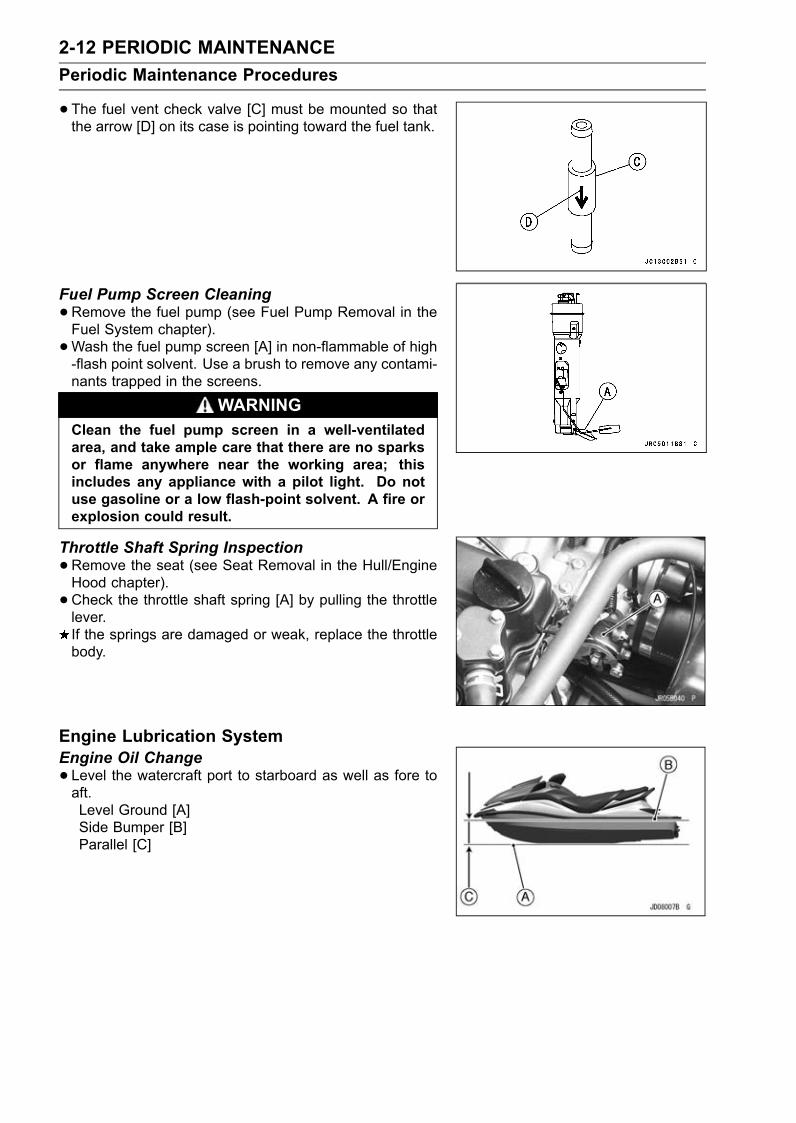
•The fuel vent check valve [C] must be mounted so thatthe arrow [D] on its case is pointing toward the fuel tank.
Fuel Pump Screen Cleaning•Remove the fuel pump (see Fuel Pump Removal in theFuel System chapter).•Wash the fuel pump screen [A] in non-flammable of high-flash point solvent. Use a brush to remove any contami-nants trapped in the screens.
WARNINGClean the fuel pump screen in a well-ventilatedarea, and take ample care that there are no sparksor flame anywhere near the working area; thisincludes any appliance with a pilot light. Do notuse gasoline or a low flash-point solvent. A fire orexplosion could result.
Throttle Shaft Spring Inspection•Remove the seat (see Seat Removal in the Hull/EngineHood chapter).• Check the throttle shaft spring [A] by pulling the throttlelever.If the springs are damaged or weak, replace the throttlebody.
Engine Lubrication SystemEngine Oil Change• Level the watercraft port to starboard as well as fore toaft.Level Ground [A]Side Bumper [B]Parallel [C]

PERIODIC MAINTENANCE 2-13Periodic Maintenance Procedures
• In a well-ventilated area, start the engine while cooling thecooling system.Open the front storage compartment cover (see FrontStorage Compertment Cover Removal in the Hull/EngineHood chapter).Remove the flushing cap (see Cooling System Flushingin the Periodic Maintenance chapter).Screw a garden hose adapter [A] onto the flushing fitting[B].Attach a garden hose [C] to a garden hose adapter andsecure the hose clamp [D].•Warm up the engine and stop it.
CAUTIONThe engine must be running before the water isturned on and the water must be turned off beforethe engine is stopped.Do not run the engine without cooling water flow formore than 15 seconds.
•Remove the seat (see Seat Removal in the Hull/EngineHood chapter).• Remove the oil filler cap [B] and the dipstick [A].
CAUTIONBe careful not to allow any dirt or foreign materialsto enter the engine.
•Drain the oil thorough from the dipstick tube [A] using acommercially-available vacuum pump [B].
WARNINGDo not discard the engine oil as the engine oil istoxic substance and will pollute the environment.Contact your local authority for approved disposalmethods.
•Pour in the specified type and amount of oil through theoil filler opening [A].
Engine OilGrade: API SE, SF or SG
API SH, SJ or SL with JASO MAViscosity: SAE 10W-40Amount: 4.0 L (4.2 US qt, with or without the filter)
5.0 L (5.3 US qt, when engine is completelydry)
2-14 PERIODIC MAINTENANCEPeriodic Maintenance Procedures
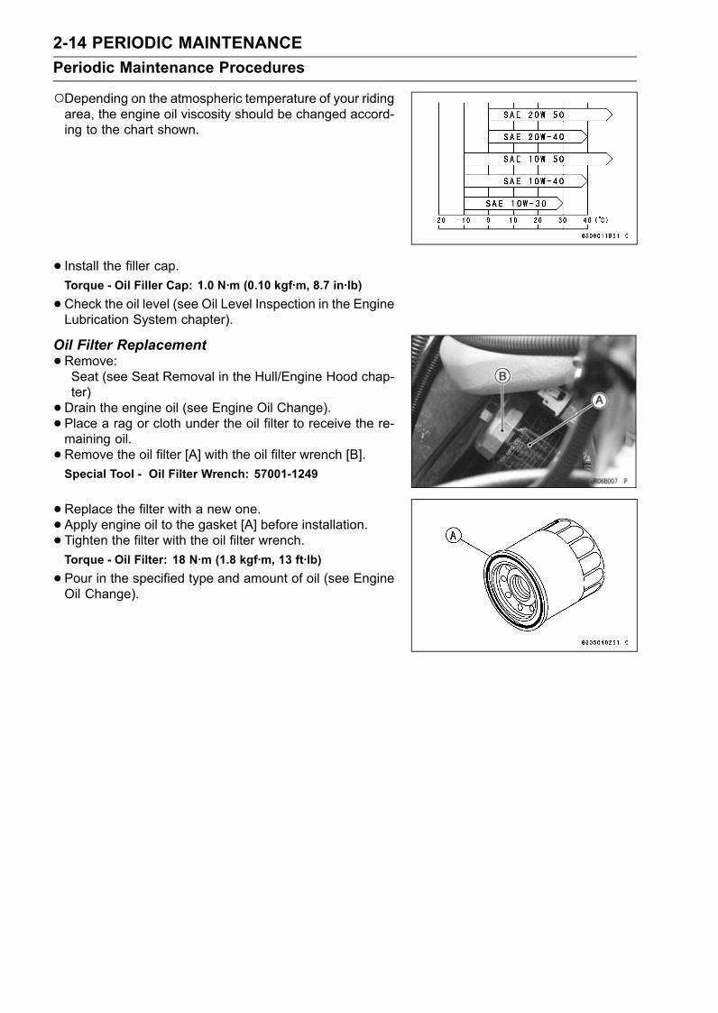
Depending on the atmospheric temperature of your ridingarea, the engine oil viscosity should be changed accord-ing to the chart shown.
• Install the filler cap.Torque - Oil Filler Cap: 1.0 N·m (0.10 kgf·m, 8.7 in·lb)
•Check the oil level (see Oil Level Inspection in the EngineLubrication System chapter).
Oil Filter Replacement•Remove:Seat (see Seat Removal in the Hull/Engine Hood chap-ter)• Drain the engine oil (see Engine Oil Change).• Place a rag or cloth under the oil filter to receive the re-maining oil.• Remove the oil filter [A] with the oil filter wrench [B].Special Tool - Oil Filter Wrench: 57001-1249
•Replace the filter with a new one.• Apply engine oil to the gasket [A] before installation.• Tighten the filter with the oil filter wrench.Torque - Oil Filter: 18 N·m (1.8 kgf·m, 13 ft·lb)
•Pour in the specified type and amount of oil (see EngineOil Change).

PERIODIC MAINTENANCE 2-15Periodic Maintenance Procedures
Engine Top EndAir Suction Valve Inspection•Remove the air suction valve (see Air Suction Valve Re-moval in the Engine Top End chapter).• Visually inspect the reeds [A] for cracks, folds, warps,heat damage, or other damage.If there is any doubt as to the condition of the reed, replacethe air suction valve as an assembly.• Check the reed contact areas [B] of the valve holder forgrooves, scratches, any signs of separation from theholder, or heat damage.If there is any doubt as to the condition of the reed contactareas, replace the air suction valve as an assembly.If any carbon or other foreign particles have accumulatedbetween the reed and the reed contact area, wash thevalve assembly with a high-flash point solvent.
CAUTIONDo not scrape off the deposits with a scraper as thiscould damage the rubber, requiring replacement ofthe suction valve assembly.
Valve Clearance InspectionNOTE
Valve clearance must be checked and adjusted whenthe engine is cold (at room temperature).
•Remove:Seat (see Seat Removal in the Hull/Engine Hood chap-ter)Air Filter (see Air Filter Removal in the Fuel (DFI) Systemchapter)Cylinder Head Cover (see Cylinder Head Cover Re-moval in the Engine Top End chapter)• Position the crankshaft at #1, #4 piston TDC as follows.Using the shaft wrench [A], turn the crankshaft counter-clockwise [B] and set the crankshaft at #1, 4 piston TDC.Special Tool - Shaft Wrench: 57001-1551

2-16 PERIODIC MAINTENANCEPeriodic Maintenance Procedures
The timing marks [A] must be aligned with the cylinderhead upper surface [B] as shown.
•Measure the valve clearance between the cam and thevalve lifter with a thickness gauge [A].
Valve ClearanceStandard:IN 0.15 ∼ 0.24 mm (0.0059 ∼ 0.0094 in.)EX 0.22 ∼ 0.31 mm (0.0087 ∼ 0.0122 in.)
When positioning #1 piston TDC at the end of thecompression stroke:Inlet Valve Clearance of #1 and #3 CylindersExhaust Valve Clearance of #1 and #2 CylindersMeasuring Valve [•]Bow [A]Camshaft Sprocket Position [B]
When positioning #4 piston TDC at the end of thecompression stroke:Inlet Valve Clearance of #2 and #4 CylindersExhaust Valve Clearance of #3 and #4 CylindersMeasuring Valve [•]Bow [A]Camshaft Sprocket Position [B]
If the valve clearance is not within the specified range,first record the clearance, and then adjust it.

PERIODIC MAINTENANCE 2-17Periodic Maintenance Procedures
•To change the valve clearance, remove the camshaftchain tensioner, camshafts and valve lifters. Replace theshim with one of a different thickness.
NOTEMark and record the valve lifter and shim locations sothey can be reinstalled in their original positions.If there is no clearance, select a shim which is severalsizes smaller and then measure the clearance.
•To select a new shim which brings the valve clearancewithin the specified range, refer to the Valve ClearanceAdjustment Charts.
Bisides the standard shims in the valve clearance adjust-ment charts, the following additional shims maybe used.
Adjustment ShimsPart Number Thickness92025-1982 2.425 mm92025-1983 2.475 mm92025-1984 2.525 mm92025-1985 2.575 mm92180-1058 2.375 mm92180-1059 2.625 mm92180-1194 2.675 mm92180-1195 2.725 mm92180-1196 2.775 mm
•Clean the shim to remove any dust or oil.•Measure the thickness of the removed shim [A].

2-18 PERIODIC MAINTENANCEPeriodic Maintenance Procedures
INLET VALVE CLEARANCE ADJUSTMENT CHART
1. Measure the clearance (when engine is cold).2. Check present shim size.3. Match clearance in vertical column with present shimsize in horizontal column.
4. Install the shim specified where the lines intersect.This shim will give the proper clearance.
ExamplePresent shim is 2.60 mm.Measured clearance is 0.35 mm.Replace 2.60 mm shim with 2.75 mm shim.
5. Remeasure the valve clearance and readjust if nec-essary.

PERIODIC MAINTENANCE 2-19Periodic Maintenance Procedures
EXHAUST VALVE CLEARANCE ADJUSTMENT CHART
1. Measure the clearance (when engine is cold).2. Check present shim size.3. Match clearance in vertical column with present shimsize in horizontal column.
4. Install the shim specified where the lines intersect.This shim will give the proper clearance.
ExamplePresent shim is 2.65 mm.Measured clearance is 0.42 mm.Replace 2.65 mm shim with 2.80 mm shim.
5. Remeasure the valve clearance and readjust if nec-essary.

2-20 PERIODIC MAINTENANCEPeriodic Maintenance Procedures
•Apply molybdenum disulfide oil to the valve lifters and ap-ply engine oil to the shims, and install them.• Install the camshafts. Be sure to install the camshaftsproperly (see Camshaft Installation in the Engine Top Endchapter).• Remeasure any valve clearance that was adjusted.• Readjust if necessary.
CAUTIONDo not put shim stock under the shim. This maycause the shim to pop out at high rpm, causing ex-tensive engine damage.Do not grind the shim. This may cause it to fracture,causing extensive engine damage.
Engine Mounting Bolts Inspection and Tightness•Check the tightness of the engine mounting bolts [A].If there are loose bolts, remove the bolts.• Apply a non-permanent locking agent to the enginemounting bolts and tighten them.Torque - EngineMounting Bolts: 36 N·m (3.7 kgf·m, 27 ft·lb)
Engine Bottom EndCoupling Damper Inspection•Remove:Seat (see Seat Removal in the Hull/Engine Hood chap-ter)Engine (see Engine Removal in the Engine Removal/In-stallation chapter)• Remove the coupling damper [A] and inspect it for wear[B] and deterioration.If it is grooved ormisshapen, replace it with a new damper.If there is any doubt as to coupler condition, replace it.
Cooling and Bilge SystemsCooling System FlushingTo prevent sand or salt deposits from accumulating in the
cooling system, it must be flushed occasionally. Flush thesystem according to the Periodic Maintenance Chart, aftereach use in salt water, or whenever there is reduced waterflow from the bypass outlet on the right side of the hull.

PERIODIC MAINTENANCE 2-21Periodic Maintenance Procedures
•Obtain a standard garden hose [A] and a garden hoseadapter [B] as shown.Garden Hose Fitting of Adapter [C]Flushing Fitting of Adapter [D]Thread: Rp 3/4 [E]
NOTEOptional part (P/No. 92005-3746) is available as a gar-den hose adapter.
•Open the front storage compartment cover (see FrontStorage Compartment Cover Removal).• Remove the flushing cap [A] on the brim of the enginecompartment.
• Screw a garden hose adapter [A] onto the flushing fitting[B].• Attach a garden hose [C] to a garden hose adapter andsecure the hose clamp [D].
• Start the engine and allow it to idle before turning on thewater.
CAUTIONThe engine must be running before the water isturned on or water may flow back through theexhaust pipe into the engine, resulting in the pos-sibility of severe internal damage.
• Immediately turn on the water and adjust the flow so thata little trickle of water comes out of the bypass outlet [A]on the right side of the hull.

2-22 PERIODIC MAINTENANCEPeriodic Maintenance Procedures
• Leave the engine idle for several minutes with the waterrunning.• Turn off the water. Leave the engine idling.• Rev the engine a few times to clear the water out of theexhaust system.
CAUTIONDo not run the engine without cooling water supplyfor more than 15 seconds, especially in high revolu-tionary speed or severe engine and exhaust systemdamage will occur.
•Switch off the engine, remove the garden hose and theadapter.• Install the flushing cap securely.Bilge System FlushingTo prevent clogging, the bilge system should be flushed
out according to the Periodic Maintenance Chart, or when-ever you suspect it is blocked.• Disconnect both bilge hoses [A] at the plastic breatherfitting [B].
• Connect the bilge filter hoses (from the hull bottom) to thegarden hoses, turn the water on, and flush it out for abouta minute. During this procedure, water will flow into theengine compartment. Do not allow a large amount of wa-ter to accumulate in the engine compartment. Removethe drain screws in the stern to drain the engine compart-ment.• Connect the other hoses (from the hull bulkhead) to thegarden hose, turn the water on, and flush it out for severalminutes.
• Before reconnecting the hoses to the plastic breather fit-ting make sure the small hole [A], on top of the breatherfitting is clear.• Reconnect the bilge hoses.

PERIODIC MAINTENANCE 2-23Periodic Maintenance Procedures
Pump and ImpellerImpeller Inspection•Examine the impeller. [A]If there is pitting, deep scratches, nicks or other damage,replace the impeller.
NOTEMinor nicks and gouges in the impeller blades can beremoved with abrasive paper or careful filing. Smoothleading edges are especially important to avoid cavita-tion.
SteeringSteering Cable/Shift Cable Inspection•Examine the steering cable or shift cable.If each cable or cable housing is kinked or frayed, replacethe cables.If the each seal [A] at either end of each cable is damagedin any way, replace the cables.
• Be certain that each cable moves freely in both directions.• Disconnect the cable joints at each end of each cable.Take out the cable joint bolt or ball joint and disconnectthe cable joint.
CAUTIONNever lay the watercraft on the right side. Water inthe exhaust system may drain back into the enginecausing serious damage.
Slide the inner cable back [A] and forth [B] in each cablehousings.If each cable does not move freely, replace it.
Handlebar Pivot Lubrication•Check the bushings for damage and wear.If the bushings are damaged or worn, replace them.•Grease:Bushings [A]

2-24 PERIODIC MAINTENANCEPeriodic Maintenance Procedures
Steering Shaft [B]
Hull/Engine HoodDrain Plug Inspection•Check the drain plugs [A] for cracks or damage and makesure the drain plug mounting screws [B] are tightened se-curely.• Check the seals [C] for damage.If necessary, replace the drain plugs or seals.
Electrical SystemBattery Charging Condition InspectionBattery charging condition can be checked by measuring
battery terminal voltage.• Disconnect the battery terminal cables (see Battery Re-moval in the Electrical System chapter).
CAUTIONBe sure to disconnect the negative terminal cablefirst.
•Measure the battery terminal voltage.NOTE
Measure with a digital voltmeter [A] which can be readone decimal place voltage.
If the reading is below the specified, refreshing charge isrequired (see Refreshing Charge in the Electrical Systemchapter).
Battery Terminal VoltageStandard: 12.8 V or more
•Connect the battery cables, positive first.

PERIODIC MAINTENANCE 2-25Periodic Maintenance Procedures
Battery Terminals Inspection•Check the battery terminal screws [A] for tightness andmake sure the terminal covers are in place.
WARNINGLoose battery cables can create sparks which cancause a fire or explosion resulting in injury or death.Make sure the battery terminal screws are tightenedsecurely and the covers are installed over the termi-nals.
•Check that the battery terminals are not corroded.If necessary, remove the battery (see Battery Removalin the Electrical System chapter) and clean the terminalsand cable ends using a solution of baking soda and water.• After attaching both cables, coat the terminals and cableends with grease to prevent corrosion.• Install the battery (see Battery Installation in the ElectricalSystem chapter).
Spark Plug Cleaning and Inspection•Remove:Seat (see Seat Removal in the Hull/Engine Hood chap-ter)Spark Plug Caps•Remove the spark plugs using the 16 mm plug wrench[A].Owner’s Tool - Spark Plug Wrench, 16 mm: 92110-1145
•Clean the spark plug, preferably in a sandblasting device,and then clean off any abrasive particles. The plug mayalso be cleaned using a high-flash point solvent and awirebrush or other tool.If the spark plug center electrode [A] and/or side elec-trode [B] are corroded or damaged, or if the insulator [C]is cracked, replace the plug. Use the standard spark plugor its equivalent.•Measure the gaps [D] with a wire-type thickness gauge.If the gap is incorrect, carefully bend the side electrodewith a tool to obtain the correct gap.Spark Plug Gap: 0.7 ∼ 0.8 mm (0.028 ∼ 0.031 in.)
• Insert the spark plug vertically into the plug hole with thespark plug installed in the plug wrench [A].Owner’s Tool - Spark Plug Wrench, 16 mm: 92110-1145
•Tighten:Torque - Spark Plugs: 13 N·m (1.3 kgf·m, 115 in·lb)

2-26 PERIODIC MAINTENANCEPeriodic Maintenance Procedures
LubricationAs in all marine craft, adequate lubrication and corrosion
protection is an absolute necessity to provide long, reliableservice. Refer to the Periodic Maintenance Chart for thefrequency of the following items:
• Lubricate the following with grease.Pull the throttle lever and hold it.Throttle Cable End [A] at Throttle Lever
Throttle Cable End [A] at Throttle Body
Remove the steering cover (see Steering Cover Removalin the Hull/Engine Hood chapter).Steering Cable Ball Joint [A] at Steering Shaft
Remove the left side cover (see Side Cover Removal inthe Hull/Engine Hood chapter).Shift Cable Ball Joint [A] at Reverse Lever

PERIODIC MAINTENANCE 2-27Periodic Maintenance Procedures
Shift Cable Ball Joint [A] at Reverse Bucket
• Lubricate the following with a penetrating rust inhibitor [B].Throttle Cable [A]
Steering Nozzle Pivots [A]Reverse Bucket Pivots [B]
•With the cable disconnected at both ends, the cableshould move freely [A] within the cable housing.If cable movement is not free after lubricating, if the cableis frayed [B], or if the cable housing is kinked [C], replacethe cable.

2-28 PERIODIC MAINTENANCEPeriodic Maintenance Procedures
All Hoses, Hose Clamps, Nuts, Bolts and Fasteners CheckNuts, Bolts, and Fasteners Tightness Inspection•Check the tightness of the bolts and nuts listed here. Also,check to see that each cotter pin is in place and in goodcondition.
NOTEFor the engine fasteners, check the tightness of themwhen the engine is cold (at room temperature).
If there are loose fasteners, retighten them to the spec-ified torque following the specified tightening sequence.Refer to the appropriate chapter for torque specifications.If torque specifications are not in the appropriate chapter,see the Standard Torque Table. For each fastener, firstloosen it by 1/2 turn, then tighten it.If cotter pins are damaged, replace them with new ones.
Nut, Bolt and Fastener to be checkedEngine:Oil Filter CartridgeEngine Mounting Bolts (and bracket bolts)Engine Damper Mounting BoltsCylinder Head Cover BoltsCylinder Head Bolts
Drive Shaft, Pump, and Impeller:Drive Shaft Holder Mounting BoltsPump Mounting BoltsPump Cover Mounting BoltsPump Grate Mounting BoltsSteering Nozzle Pivot BoltsReverse Bucket Pivot Bolts
Steering:Handlebar Clamp BoltsSteering Neck Mounting BoltsSteering Holder Mounting BoltsSteering Shaft LocknutSteering Cable NutSteering Cable Joint BoltShift (reverse) Cable Nut
Hull and Engine Hood:Stabilizer Mounting BoltsRear Grip Plate Mounting Bolts
Electrical System:Spark PlugsBattery Terminal
Hose and Hose Connect Inspection•Check the following hoses for leakage [A], hardening,cracking [B], checking, cuts, abrasions, breaks andbulges [C]. And make sure the hoses are not kinked orpinched.Fuel Vent HoseOil HosesCooling HosesBilge HosesIf a hose is damaged in any way, replace it immediatelyand check all the others for damage.

PERIODIC MAINTENANCE 2-29Periodic Maintenance Procedures
•Make sure the above hoses are routed properly and se-cured with the clamps away from any moving parts andsharp edged portions.Plastic Clamp [A]Hose [B]Hose Fitting [C]
NOTEThe majority of bilge hoses have no clamps at the hoseends.
Metal Clamp [A]Hose [B]Hose Fitting [C]
NOTECheck the fuel and exhaust tubes for signs of wear, de-terioration, damage or leakage. Replace if necessary.Make sure the above tubes are secured with the metalgear clamps away from any parts.
• If the watercraft is not properly handled, the high pres-sure inside the fuel line can cause fuel to leak [A] or thehose to burst. Remove the seat (see Seat Removal in theHull/Engine Hood chapter) and check the fuel hose.Replace the fuel hose if any fraying, cracks [B] or bulges[C] are noticed.
• Check that the hoses are routed according to Cable, Wire,and Hose Routing section in the Appendix chapter.Replace the hose if it has been sharply bent or kinked.Hose Joints [A]Fuel Hose [B]
• Check that the hose joints are securely connected.Push and pull [A] the hose joint [B] back and forth morethan two times, and make sure it is locked.If it does not locked, reinstall the hose joint.
WARNINGMake sure the hose joint is installed correctly on thedelivery pipe by sliding the joint, or the fuel couldleak.

2-30 PERIODIC MAINTENANCEPeriodic Maintenance Procedures
Rubber Strap Inspection•Check the following rubber straps for any deterioration ordamage. Pull on squeeze the straps and look for cracks.Battery Straps [A]Fuel Tank StrapsWater Box Muffler StrapsIf a strap is damage in any way, replace it.
FUEL SYSTEM (DFI) 3-1
3
Fuel System (DFI)Table of Contents
Fuel System Diagram........................ 3-3Exploded View................................... 3-4Specifications .................................... 3-10Special Tools and Sealant ................. 3-12DFI Parts Location............................. 3-14DFI System........................................ 3-16DFI Servicing Precautions ................. 3-19Self-Diagnosis ................................... 3-21Self-diagnosis Outline..................... 3-21Service Code (Character) Table ..... 3-22
Troubleshooting the DFI System ....... 3-24Throttle Sensor (ServiceCode/Character-11/tPS) ................. 3-26Throttle Sensor Removal/Adjust-ment .......................................... 3-26
Input Voltage Inspection............... 3-27Output Voltage Inspection............ 3-29Resistance Inspection.................. 3-30
Inlet Air Pressure Sensor (ServiceCode/Character-12/bOSt)............... 3-32Inlet Air Pressure SensorRemoval .................................... 3-32
Inlet Air Pressure SensorInstallation ................................. 3-32
Input Voltage Inspection............... 3-32Output Voltage Inspection............ 3-33
Inlet Air Temperature Sensor (ServiceCode/Character-13/AIrt) ................. 3-35Inlet Air TemperatureRemoval/Installation.................. 3-35
Output Voltage Inspection............ 3-35Sensor Resistance Inspection ..... 3-36
Water Temperature Sensor (ServiceCode/Character-14/AqUt) ............... 3-38Water Temperature SensorRemoval/Installation.................. 3-38
Output Voltage Inspection............ 3-38Sensor Resistance Inspection ..... 3-40
Crankshaft Sensor (ServiceCode/Character-21/CrAg)............... 3-41Crankshaft SensorRemoval/Installation.................. 3-41
Crankshaft Sensor Inspection...... 3-41Camshaft Position Sensor (ServiceCode/Character-23/CAA1).............. 3-42Camshaft Position SensorRemoval/Installation.................. 3-42
Camshaft Position SensorInspection.................................. 3-42
Vehicle-down Sensor (ServiceCode/Character-31/dOS)................ 3-43Vehicle-down Sensor Removal .... 3-43Vehicle-down Sensor Installation . 3-43Vehicle-down Sensor Inspection.. 3-44
Immobilizer Amplifier (ServiceCode/Character-35/IdA).................. 3-46Amplifier Input Voltage Inspection 3-46
Key Collation Error (ServiceCode/Character-36/IdEr) ................ 3-47User Key Inspection..................... 3-47
Ignition Coils (ServiceCode/Character-51, 52/COL1,COL2) ............................................. 3-48Ignition Coil Removal/Installation. 3-48Input Voltage Inspection............... 3-48
Engine Overheating (ServiceCode/Character-71/HEAt)............... 3-50
Low Engine Oil Pressure (ServiceCode/Character-72/OILP)............... 3-51
Oil Temperature Sensor (ServiceCode/Character-73/OILt) ................ 3-52Oil Temperature SensorRemoval/Installation.................. 3-52
Output Voltage Inspection............ 3-52Sensor Resistance Inspection ..... 3-53
Main (ECU) Relay and System Relay(Service Code/Character-75/rEL) ... 3-54Relay Assembly Removal ............ 3-54Relay Assembly Inspection.......... 3-54
Engine Oil Overheating (ServiceCode/Character-76/OILH)............... 3-55
Fuel Injectors ..................................... 3-56Fuel Injector Removal .................. 3-56Fuel Injector Installation ............... 3-56Audible Inspection........................ 3-57Injector Signal Test....................... 3-57Injector Resistance Inspection ..... 3-58Injector Unit Test .......................... 3-58Injector Voltage Inspection........... 3-59Injector Fuel Line Inspection ........ 3-60
ECU................................................... 3-62ECU Removal .............................. 3-62ECU Installation ........................... 3-62ECU Power Supply Inspection..... 3-62
DFI Power Source ............................. 3-65Main Fuse Inspection................... 3-65Relay Assembly Removal ............ 3-65Relay Assembly Inspection.......... 3-65
Throttle Lever, Cable and Case......... 3-66

3-2 FUEL SYSTEM (DFI)
Free Play Inspection .................... 3-66Throttle Cable Adjustment ........... 3-66Throttle Case Removal/Disas-sembly....................................... 3-66
Throttle Case Assembly/Installa-tion ............................................ 3-67
Throttle Cable Removal ............... 3-68Throttle Cable Installation ............ 3-69Throttle Case and CableLubrication................................. 3-70
Throttle Cable Inspection ............. 3-70Air Filter ............................................. 3-71
Air Filter Removal ........................ 3-71Air Filter Installation ..................... 3-71Air Filter Disassembly .................. 3-71Air Filter Assembly ....................... 3-72
Throttle Body Assy ............................ 3-73Idle Speed Inspection .................. 3-73High Altitude PerformanceAdjustment ................................ 3-73
Throttle Body Assy Removal........ 3-73Throttle Body Assy Installation..... 3-73Throttle Body Assy Disassembly . 3-73Throttle Bore Cleaning ................. 3-74ISC (Idle Speed Controller)Removal/Installation.................. 3-74
ISC (Idle Speed Controller)Inspection.................................. 3-74
ISC Resistance Inspection........... 3-75Inlet Manifold ..................................... 3-76
Inlet Manifold Removal ................ 3-76Inlet Manifold Installation ............. 3-78
Fuel Line............................................ 3-79Fuel Hose Removal ..................... 3-79Fuel Hose Installation .................. 3-79Fuel Pressure Inspection ............. 3-80Fuel Flow Rate Inspection ........... 3-81
Fuel Vent Check Valve ...................... 3-83Fuel Vent Check Valve Mounting . 3-83Fuel Vent Check Valve Inspection 3-83
Fuel Pump ......................................... 3-84Fuel Pump Removal .................... 3-84Fuel Pump Installation ................. 3-85Power Source Voltage Inspection 3-86Operating Voltage Inspection....... 3-87Fuel Pump Relay Removal .......... 3-88Fuel Pump Relay Inspection ........ 3-88
Fuel Tank........................................... 3-89Fuel Tank Removal ...................... 3-89Fuel Tank Installation ................... 3-90Fuel Tank Cleaning ...................... 3-90Fuel Filler and Tube Removal ...... 3-91Fuel Filler and Tube Installation... 3-92

FUEL SYSTEM (DFI) 3-3Fuel System Diagram
1. Fuel Pump2. Fuel Hose3. Supply Line4. Delivery Pipe5. Fuel Injectors6. Fuel Tank

3-4 FUEL SYSTEM (DFI)Exploded View

FUEL SYSTEM (DFI) 3-5Exploded View
TorqueNo. Fastener
N·m kgf·m ft·lbRemarks
1 Vehicle-down Sensor Mounting Screws 1.5 0.15 13 in·lb2 Bracket Mounting Bolts 8.8 0.90 78 in·lb L3 Inlet Manifold Mounting Bolts 25 2.5 18 L4 Inlet Manifold Mounting Nuts 20 2.0 145 Delivery Pipe Mounting Bolts 7.8 0.80 69 in·lb6 Inlet Air Pressure Sensor Bolts 7.8 0.80 69 in·lb7 Inlet Air Temperature Sensor 20 2.0 148 Throttle Body Assy Mounting Bolts 20 2.0 149 Inlet Manifold Drain Plug 20 2.0 1410 Inlet Manifold Plate Bolts 7.8 0.80 69 in·lb11 Crankshaft Sensor Screws 4.4 0.45 39 in·lb L12 Camshaft Position Sensor Bolt 7.8 0.80 69 in·lb L13 Water Temperature Sensor 15 1.5 11 see text14 Oil Temperature Sensor 15 1.5 11 see text15 ECU Mounting Bolts 3.0 0.3 27 in·lb L16 Relay Bolts 2.5 0.25 22 in·lb L17 Throttle Sensor Mounting Screws 2.0 0.20 18 in·lb18 ISC Actuator Mounting Bolts 4.9 0.50 43 in·lb19 Fuse Bracket Bolt 2.5 0.25 22 in·lb L20 Harness Bolts 8.8 0.90 78 in·lb L21. Ignition Coils22. Fuel InjectorsEO: Fill the hollow with the engine oil (10W-30).G: Apply grease.L: Apply a non-permanent locking agent.R: Replacement PartsSi: Fill the hollow with the specified silicone grease (Kawasaki Bond: 92137-1002).SO: Apply silicone oil to the O-ring.SS: Apply silicone sealant (see text).

3-6 FUEL SYSTEM (DFI)Exploded View

FUEL SYSTEM (DFI) 3-7Exploded View
TorqueNo. Fastener
N·m kgf·m ft·lbRemarks
1 Fuel Filler Tube Clamp Screws 2.9 0.30 26 in·lb2 Fuel Pump Holder Clamp Screws 2.9 0.30 26 in·lb3. Meter Unit4. Buzzer5. Fuel Vent Check Valve6. Fuel Pump

3-8 FUEL SYSTEM (DFI)Exploded View

FUEL SYSTEM (DFI) 3-9Exploded View
TorqueNo. Fastener
N·m kgf·m ft·lbRemarks
1 Air Filter Mounting Bolts 8.8 0.90 69 in·lb L2 Air Filter Bracket Mounting Bolts 7.8 0.80 69 in·lb L3 Throttle Cable Locknut 20 2.0 14 in·lb4 Throttle Case Mounting Screws 3.9 0.40 34 in·lbG: Apply grease.L: Apply a non-permanent locking agent.

3-10 FUEL SYSTEM (DFI)Specifications
Item StandardDigital Fuel Injection SystemIdle Speed 1 300 ±100 r/min (rpm) - both in and out of waterThrottle Assy:Type Single typeBore 60 (2.36 in.)
ECU (Electronic Control Unit):Make Mitsubishi ElectricType Digital memory type, with built in IC igniter, sealed with
resinOperating range Engine speed range 100 ∼ 8 100 r/min (rpm)
Fuel Pressure (High Pressure Line):Engine Idling approx. 294 kPa (3.0 kgf/cm², 43 psi)
Fuel Pump:Type Impeller typeDischarge 83 mL or more for 3 seconds
Throttle Sensor:Input Voltage 4.75 ∼ 5.25 V DC between R and BK/W leadsOutput Voltage 1.08 ∼ 1.18 V DC between G/W and BK/W leads (at idle
throttle opening)Resistance 4 ∼ 6 kΩ
Inlet Air Pressure Sensor:Input Voltage 4.75 ∼ 5.25 V DC between R and BK/W leadsOutput Voltage 3.75 ∼ 4.25 V DC between G/R and BK/W leads at standard
atmospheric pressureInlet Air Temperature Sensor:Output Voltage at ECU about 2.3 ∼ 2.6 V @20°C (68°F)Resistance 5.4 ∼ 6.6 kΩ at 0°C (32°F)
2.26 ∼ 2.86 kΩ at 20°C (68°F)0.29 ∼ 0.39 kΩ at 80°C (176°F)
Water Temperature Sensor:Resistance see Electrical System chapterOutput Voltage at ECU about 3 ∼ 4 V @20°C (68°F)
Vehicle-down Sensor:Detection Method Magnetic flux detection methodDetection Angle more than 110 ∼ 130° for each bank
Output Voltage with sensor tilted 110 ∼ 130° or more: 0.65∼ 1.35 Vwith sensor arrow mark pointed up: 3.55 ∼ 4.45 V
Fuel Injectors:Type INP-281Nozzle Type One spray type with 4 holesResistance about 11.7 ∼ 12.3 Ω at 20°C (68°F)
Oil Temperature Sensor:Resistance same to water temperature sensorOutput Voltage at ECU about 3 ∼ 4 V @20°C (68°F)
FUEL SYSTEM (DFI) 3-11Specifications
Item StandardThrottle Lever and CablesThrottle Lever Free Play about 2 mm (0.08 in.)
3-12 FUEL SYSTEM (DFI)Special Tools and Sealant
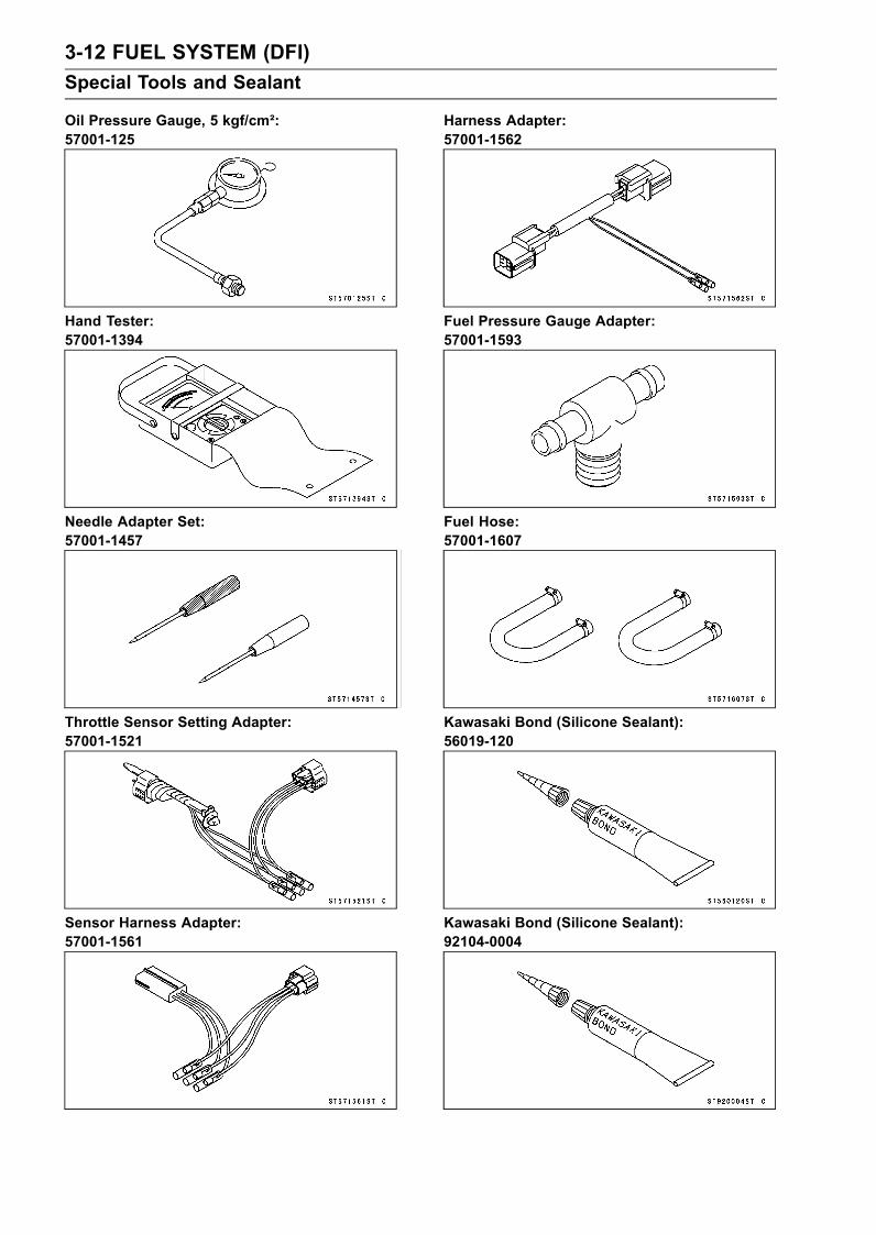
Oil Pressure Gauge, 5 kgf/cm²:57001-125
Hand Tester:57001-1394
Needle Adapter Set:57001-1457
Throttle Sensor Setting Adapter:57001-1521
Sensor Harness Adapter:57001-1561
Harness Adapter:57001-1562
Fuel Pressure Gauge Adapter:57001-1593
Fuel Hose:57001-1607
Kawasaki Bond (Silicone Sealant):56019-120
Kawasaki Bond (Silicone Sealant):92104-0004

FUEL SYSTEM (DFI) 3-13Special Tools and Sealant
Kawasaki Bond (Silicone Grease):92137-1002

3-14 FUEL SYSTEM (DFI)DFI Parts Location
1. Fuel Injector #12. Fuel Injector #23. Fuel Injector #34. Fuel Injector #45. Inlet Air Pressure Sensor6. Inlet Air Temperature Sensor7. Throttle Sensor8. ISC (Idle Speed Controller)9. Camshaft Position Sensor10. Water Temperature Sensor11. Crankshaft Sensor12. Oil Pressure Switch13. Oil Temperature Sensor

FUEL SYSTEM (DFI) 3-15DFI Parts Location
14. Ignition Switch15. Meter Unit16. Buzzer17. Fuel Pump18. Fuel Level Sensor19. Vehicle-down Sensor20. Ignition Coil #1, #421. Ignition Coil #2, #322. Main Fuse 20 A23. ECU (Electronic Control Unit)24. ECU Main Relay25. Fuel Pump Relay26. Battery27. Diagnosis Connector

3-16 FUEL SYSTEM (DFI)DFI System
DFI System Wiring Diagram

FUEL SYSTEM (DFI) 3-17DFI System
1. ECU2. Joint Connector 8 (Vcc)3. Joint Connector 7 (Vcc)4. Joint Connector 6 (Power (5 V) - Sensor)5. Joint Connector 5 (Ground - Sensor)6. Joint Connector 4 (Power (12 V) - Injector)7. Injector #48. Injector #39. Injector #210. Injector #111. Inlet Air Temperature Sensor12. Inlet Air Pressure Sensor13. Crankshaft Sensor14. System Relay15. Fuel Pump Relay16. Main (ECU) Relay17. Joint Connector 3 (Switch (12 V))18. Vehicle-down Sensor19. Fuel Pump20. Joint Connector 221. Joint Connector 122. Ignition Switch (Immobilizer Amplifier)23. Joint Connector 15 (Ground)24. Multifunction Meter25. Engine Stop Switch/Tether26. Engine Start Switch27. Joint Connector 1328. Joint Connector 12 (Ground)29. Joint Connector 11 (Ground)30. Battery31. Main Fuse 20 A32. Spark Plugs33. Ignition Coils34. Joint Connector 10 (Ignition Coil (12 V))35. Plug Nonuse36. Plug Connector for DIAG and key Registration37. Water Temperature Sensor38. Camshaft Position Sensor (Exhaust)39. Throttle Sensor40. Oil Temperature Sensor41. Joint Connector 9 (Ground Control)42. Oil Pressure Switch

3-18 FUEL SYSTEM (DFI)DFI System
Terminal Numbers of ECU Connectors
Terminal Names1. ISC (Idle Speed Controller)2. ISC (Idle Speed Controller)3. Oil Pressure Switch4. Unused5. Crankshaft Sensor (–)6. Unused7. Camshaft Position Sensor8. Unused9. Power Supply to Sensors10. External Communication Line (Immobilizer
System)11. Water Temperature Sensor12. Immobilizer Amplifier13. Oil Temperature Sensor14. External Communication Line (*KDS)15. Ground for Control System16. External Communication Line (to unused
connector)17. Battery (+)18. ISC (Idle Speed Controller)19. ISC (Idle Speed Controller)20. Engine Stop Switch21. Steering Position Sensor22. Crankshaft Sensor (+)23. Inlet Air Pressure Sensor24. Unused25. Unused26. Vehicle-down Sensor
27. Unused28. Inlet Air Temperature Sensor29. Meter (DIAG)30. Throttle Sensor31. Immobilizer Amplifier32. Ground for Sensor33. External Communication Line (to unused
connector)34. Battery Monitor35. Unused36. System Relay (–)37. Unused38. Injector #339. Ground for Power40. Main (ECU) Relay41. Unused42. Injector #143. Ignition Coil #1, #444. Main Switch (To Meter)45. Entry Switch (to Immobilizer Amplifier)46. Start Switch47. Injector #448. Ground for Power49. Fuel Pump Relay50. Ignition Coil #2, #351. Injector #252. unused

FUEL SYSTEM (DFI) 3-19DFI Servicing Precautions
There are a number of important precautions that shouldbe followed servicing the DFI system.
This DFI system is designed to be used with a 12 V sealedbattery as its power source. Do not use any other batteryexcept for a 12 V sealed battery as a power source.Do not reverse the battery cable connections. This willdamage the ECU.To prevent damage to the DFI parts, do not disconnect thebattery cables or any other electrical connections whenthe ignition switch is on, or while the engine is running.Take care not to short the leads that are directly con-nected to the battery positive (+) terminal to the engineground.When charging, remove the battery from the vehicle. Thisis to prevent ECU damage by excessive voltage.Whenever the DFI electrical connections are to be discon-nected, first turn off the ignition switch. Conversely, makesure that all the DFI electrical connections are firmly re-connected before starting the engine.Do not turn the ignition switch ON while any of the DFIelectrical connectors are disconnected. The ECU memo-rizes service codes.If a transceiver is installed on the vehicle, make sure thatthe operation of the DFI system is not influenced by elec-tric wave radiated from the antenna. Check operation ofthe system with the engine at idle. Locate the antenna asfar as possible away from the ECU.When any fuel hose is disconnected, do not turn on theignition switch. Otherwise, the fuel pump will operate andfuel will spout from the fuel hose.Do not operate the fuel pump if the pump is completelydry. This is to prevent pump seizure.Before removing the fuel system parts, blow the outer sur-faces of these parts clean with compressed air.When any fuel hose is disconnected, fuel may spout outby residual pressure in the fuel line. Cover the hose jointwith a piece of clean cloth to prevent fuel spillage.When installing the fuel hoses, avoid sharp bending, kink-ing, flattening or twisting, and route the fuel hoses with aminimum of bending so that the fuel flow will not be ob-structed.Route the hoses according to Cable, Wire, and HoseRouting section in the Appendix chapter.
Install the hose clamps in the position shown, and se-curely tighten the clamp bolts. Check the fuel system forleaks after hose installation.Fuel Hose [A]Clamp [B]Fuel Pipe [C]

3-20 FUEL SYSTEM (DFI)DFI Servicing Precautions
The high pressure inside the fuel line can cause fuel toleak [A] or the hose to burst. Bend and twist the fuel hosewhile examining it.Replace the hose if any cracks [B] or bulges [C] are no-ticed.
When checking the DFI parts, do not run the engine for15 seconds or more without auxiliary cooling (seeGeneralInformation chapter).
CAUTIONIf running the engine without the auxiliary coolingfor 15 seconds ormore (even at idle speed), the rub-ber component relative to the Exhaust System maybe damaged.
Execute the auxiliary cooling securely in case that fre-quent engine running is required.
•When checking the DFI parts, use a digital meter whichcan be read two decimal place voltage or resistance.The DFI part connectors have seals, including the ECU.When measuring the input or output voltage with theconnector joined, use the needle adapter set. Insert theneedle adapter inside the seal until the needle adapterreaches the terminal.Digital Meter [A]Special Tool - Needle Adapter Set: 57001-1457
CAUTIONInsert the needle adapter straight along the terminalin the connector to prevent short-circuit betweenterminals.
After measurement, remove the needle adapters and ap-ply silicone sealant to the seals [A] of the connector [B]for waterproofing.Silicone Sealant (Kawasaki Bond: 56019-120) - Sealsof Connector
•Always check battery condition before replacing the DFIparts. A fully charged battery is a must for conductingaccurate tests of the DFI system.•Do not directly connect a 12 V battery to a fuel injector.Insert a resistor (5 ∼ 7 Ω) or a bulb (12 V, 3 ∼ 3.4 W) inseries between the battery and the injector.

FUEL SYSTEM (DFI) 3-21Self-Diagnosis
Self-diagnosis OutlineThe self-diagnosis system has two modes and can be
switched to another mode.[A] Push the “SET” button with “MODE” button at the
same time for 3 seconds or more.[B] Push either “SET” or “MODE” button for more than
one second or more.
User ModeThis is a standard mode and enters automatically after
ignition switch ON. The ECU notifies the rider of troublesin DFI system and ignition system by going on LED warn-ing light [A] by flashing, the FI indicator [B] and “FI” char-acter [C] when DFI system and ignition system parts arefaulty, and initiates fail-safe function. The buzzer soundgoes on. In case of serious troubles ECU stops the injec-tion/ignition/starter motor operation. The buzzer sound canbe stopped by pushing either “SET” or “MODE” button.
Dealer ModeThe LCD in the meter unit displays service code charac-
ter [A] to show the problem(s) which the DFI system andignition system has at the moment of diagnosis.• To enter the dealer mode push the “SET” button [B] with“MODE” button [C] for 3 seconds or more.• Read the service code character in the LCD display. Re-fer to the “Service Code (Character) Table” in the followingsection.• To return the user mode push either “SET” or “MODE”button for one second or more.• The service code character(s) will not be shown on theLCD in the meter unit after the problems are solved.

3-22 FUEL SYSTEM (DFI)Self-Diagnosis
Service Code (Character) TableServiceCode(used inECU)
Service CodeCharacter
(displayed onMeter Unit)
Possible Problems Fail-Safe Function
11
Throttle sensor malfunction,wiring open or short
The ECU locks ignition timing intothe ignition timing at closed throttleposition and sets the DFI in the D-Jmethod (see Note 1).
12 Inlet air pressure sensormalfunction, wiring open or short
The ECU sets the DFI in the α-Nmethod (see Note 2).
13 Inlet air temperature sensormalfunction, wiring open or short
The ECU sets the inlet air temperatureat 40°C.
14 Water temperature sensormalfunction, wiring open or short
The ECU sets the water temperatureat 70°C.
21 Crankshaft sensor malfunction,wiring open or short –
23 Camshaft position sensormalfunction, wiring open or short
The ECU continues to ignite cylindersin the same sequence following thelast good signal.
31Vehicle-down sensormalfunction, wiring open orshort
The ECU slows down the enginespeed less than 3 000 r/min (rpm) bystopping the ignition.
35 Immobilizer amplifier malfunction –
36 Key collation error –
45 Fuel pump relay malfunction,wiring open –
46 Fuel pump relay malfunction,relay is stuck –
51 Ignition coil #1, #4 malfunction,wiring open or short
The ECU shuts off the injectors #1/#4to stop fuel to the cylinders #1/#4.
52 Ignition coil #2, #3 malfunction,wiring open or short
The ECU shuts off the injectors #2/#3to stop fuel to the cylinders #2/#3.
71 Engine overheatThe ECU slows down the enginespeed less than 3 000 r/min (rpm) bystopping the ignition.
72 Engine oil pressure too lowThe ECU slows down the enginespeed less than 3 000 r/min (rpm) bystopping the ignition.
73
Oil temperature sensormalfunction, wiring open orshort
The ECU sets the oil temperature at60°C.The ECU slows down the enginespeed less than 3 000 r/min (rpm) bystopping the ignition.

FUEL SYSTEM (DFI) 3-23Self-Diagnosis
ServiceCode(used inECU)
Service CodeCharacter
(displayed onMeter Unit)
Possible Problems Fail-Safe Function
75Main (ECU) relay and systemrelay malfunction, wiring is openor relay is stuck
–
76 Engine oil overheatThe ECU slows down the enginespeed less than 3 000 r/min (rpm) bystopping the ignition.
Note:(1) D-J Method: the DFI control method from medium to heavy engine load. When the engine load
is light like at idling or low speed, the ECU determines the injection quantity by calculating fromthe throttle vacuum (vacuum sensor output voltage) and engine speed (crankshaft sensor outputvoltage).
(2) α-N Method: As the engine speed increases, and the engine load turns middle to heavy, the ECUdetermines the injection quantity by calculating from the throttle opening (throttle sensor outputvoltage) and the engine speed.
(3) If both throttle sensor system and inlet air pressure fails, the ECU locks ignition timing into theignition timing at closed throttle position and sets the DFI in the α-N method.
(4) The ECU may be involved in these problems. If all the parts and circuits checked out good, besure to check the ECU for ground and power supply. If the ground and power supply are checkedgood, replace the ECU.
Memory of Service Code (Character)The service codes (characters) in the past are stored in the ECU. However, the characters cannot bedisplayed in the meter. The past service codes can be confirmed by using the Kawasaki DiagnosticSystem (see General Information chapter), and they can be erased.
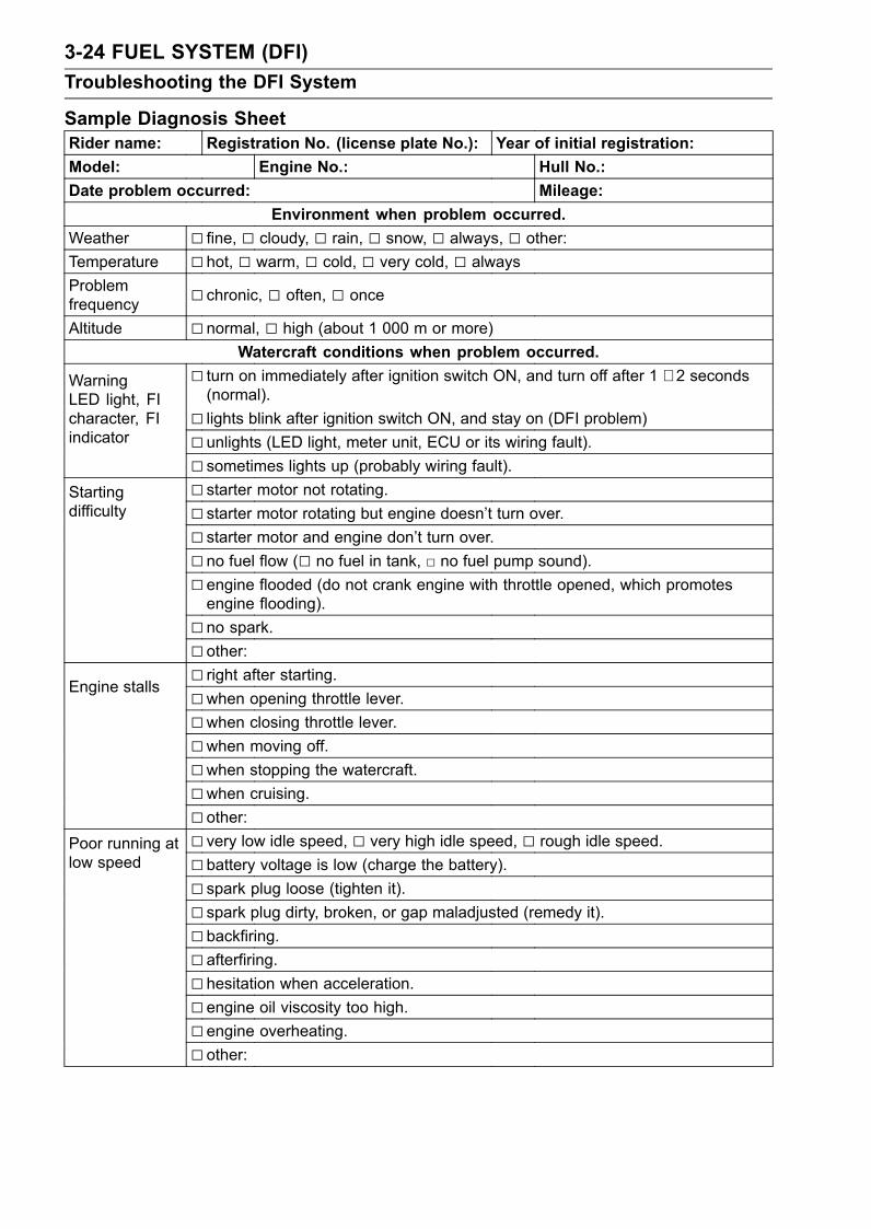
3-24 FUEL SYSTEM (DFI)Troubleshooting the DFI System
Sample Diagnosis SheetRider name: Registration No. (license plate No.): Year of initial registration:Model: Engine No.: Hull No.:Date problem occurred: Mileage:
Environment when problem occurred.Weather fine, cloudy, rain, snow, always, other:Temperature hot, warm, cold, very cold, alwaysProblemfrequency chronic, often, once
Altitude normal, high (about 1 000 m or more)Watercraft conditions when problem occurred.
turn on immediately after ignition switch ON, and turn off after 1 ∼ 2 seconds(normal).
lights blink after ignition switch ON, and stay on (DFI problem)
WarningLED light, FIcharacter, FIindicator unlights (LED light, meter unit, ECU or its wiring fault).
sometimes lights up (probably wiring fault). starter motor not rotating.Starting
difficulty starter motor rotating but engine doesn’t turn over. starter motor and engine don’t turn over. no fuel flow ( no fuel in tank, no fuel pump sound). engine flooded (do not crank engine with throttle opened, which promotesengine flooding).
no spark. other: right after starting.
Engine stalls when opening throttle lever.when closing throttle lever.when moving off.when stopping the watercraft.when cruising. other: very low idle speed, very high idle speed, rough idle speed.Poor running at
low speed battery voltage is low (charge the battery). spark plug loose (tighten it). spark plug dirty, broken, or gap maladjusted (remedy it). backfiring. afterfiring. hesitation when acceleration. engine oil viscosity too high. engine overheating. other:

FUEL SYSTEM (DFI) 3-25Troubleshooting the DFI System
spark plug loose (tighten it). spark plug dirty, broken, or gap maladjusted (remedy it). spark plug incorrect (replace it).
Poor runningor no power athigh speed
knocking (fuel poor quality or incorrect). engine overheating. engine oil level too high. engine oil viscosity too high. other:

3-26 FUEL SYSTEM (DFI)Throttle Sensor (Service Code/Character-11/tPS)
Throttle Sensor Removal/AdjustmentCAUTION
Never drop the throttle sensor [A], especially on ahard surface. Such a shock to the sensor can dam-age it.
•Remove:Seat (see Seat Removal in the Hull/Engine Hood chapter)Air filter (see air Filter Removal)
• Use a Torx wrench [A] (T20, B = 3.86 mm (0.152 in.)) toremove the throttle sensor mounting screws [C].
NOTEIn the engine compartment, there is not enough spacebetween the throttle sensor and hull to remove the Torxscrews. So use an L shape Torx wrench.
•When installing the throttle sensor, note the following (Inthe photo, the throttle sensor has been removed from thethrottle body for clarity).
Align [A] the projections [B] on the throttle sensor with thethrottle shaft [C] as shownwhen putting the throttle sensorto the throttle body.
Turn the throttle sensor counterclockwise [A] a little andtemporarily tighten the throttle sensor mounting screws.

FUEL SYSTEM (DFI) 3-27Throttle Sensor (Service Code/Character-11/tPS)
•Adjust the throttle sensor positioning as follows.Install the air filter temporarily.After warming up the engine, check the idling speed.Idle SpeedStandard: 1 300 ±100 r/min (rpm)
Stop the engine and turn the ignition switch OFF.Disconnect the throttle sensor connector and connect thethrottle sensor setting adapter [A] between the harnessconnector and throttle sensor connector.Connect a digital meter to the sensor setting adapterleads.Special Tool - Throttle Sensor Setting Adapter: 57001
-1521
Throttle Sensor Output VoltageConnections to SensorMeter (+)→ G/W leadMeter (–)→ BK/W lead
Start the engine with idle speed.Turn [A] the throttle sensor and bring the sensor outputvoltage within the standard range.
Output Voltage at SensorStandard: 1.08 ∼ 1.18 V DC (at idle throttle opening)
Tighten the throttle sensor mounting screws.Torque - Throttle Sensor Mounting Screws: 2.0 N·m (0.20
kgf·m, 18 in·lb)Recheck the sensor output voltage is within the standardrange.Stop the engine and turn the ignition switch OFF.Remove the setting adapter and reconnect the throttlesensor connector.
Input Voltage InspectionNOTE
Be sure the battery is fully charged.•Turn the ignition switch OFF.•Remove the ECU (see ECURemoval). Do not disconnectthe ECU connector.
• Connect a digital voltmeter [A] to the connector [B], usingthe needle adapter set.Special Tool - Needle Adapter Set: 57001-1457
Throttle Sensor Input VoltageConnections to ECUMeter (+)→ R lead (terminal 9)Meter (–)→ BK/W lead (terminal 32)

3-28 FUEL SYSTEM (DFI)Throttle Sensor (Service Code/Character-11/tPS)
•Turn the ignition switch ON and push the lanyard key un-der the stop button.• Pushing the start button, run the engine 5 ∼ 6 seconds atidling to measure the sensor input voltage.Wait 15 seconds before using the starter again.Input Voltage at ECUStandard: 4.75 ∼ 5.25 V DC
•Turn the ignition switch OFF.If the reading of input voltage is less than the standard,check the ECU for its ground, power supply and wiringshorted. If the ground, power supply and wiring are good,replace the ECU.If the input voltage is within the standard range, check theinput voltage at the throttle sensor connector.• Remove the air filter temporarily (see Air Filter Removal).• Disconnect the throttle sensor connector and connect thesetting adapter [A] between the harness connector andthrottle sensor connector.• Connect a digital meter to the setting adapter leads.Special Tool - Throttle Sensor Setting Adapter: 57001
-1521
Throttle Sensor Input VoltageConnections to SensorMeter (+)→ R leadMeter (–)→ BK/W lead
• Install the air filter.• Turn the ignition switch ON and push the lanyard key un-der the stop button.• Pushing the start button, run the engine 5 ∼ 6 seconds atidling to measure the sensor input voltage.Wait 15 seconds before using the starter again.Input Voltage at SensorStandard: 4.75 ∼ 5.25 V DC
•Turn the ignition switch OFF.If the reading is out of the range, check the wiring (seewiring diagram in this section).If the reading is good, check the output voltage of thesensor.

FUEL SYSTEM (DFI) 3-29Throttle Sensor (Service Code/Character-11/tPS)
Output Voltage Inspection•Measure the output voltage at the ECU in the same wayas input voltage inspection. Note the following.Digital Voltmeter [A]Connector [B]Special Tool - Needle Adapter Set: 57001-1457
Throttle Sensor Output VoltageConnections to ECUMeter (+) → G/W lead (terminal 30)Meter (–) → BK/W lead (terminal 32)
•Start the engine.• Check idle speed to ensure throttle opening is correct.Idle SpeedStandard: 1 300 ±100 r/min (rpm)
•Measure the sensor output voltage with the idle speed.Output Voltage at ECUStandard: 1.08 ∼ 1.18 V DC (at idle throttle opening)
CAUTIONNever drop the throttle sensor can especially on ahard surface. A shock to the sensor can damage it.
If the output voltage is within the standard range, checkthe ECU for a good ground, and power supply (see ECUPower Supply Inspection). If the ground and power sup-ply are good, replace the ECU.If the output voltage is far out of the standard range (e.g.when the wiring is open, the reading is 0 V), check theoutput voltage at the sensor connector.

3-30 FUEL SYSTEM (DFI)Throttle Sensor (Service Code/Character-11/tPS)
•Disconnect the throttle sensor connector and connect thesetting adapter [A] between the harness connector andthrottle sensor connector.• Connect a digital meter to the setting adapter leads.Special Tool - Throttle Sensor Setting Adapter: 57001
-1521
Throttle Sensor Output VoltageConnections to SensorMeter (+) → G/W leadMeter (–) → BK/W lead
•Measure the sensor output voltage with the idle speed.Output Voltage at SensorStandard: 1.08 ∼ 1.18 V DC (at idle throttle opening)
CAUTIONNever drop the throttle sensor, especially on a hardsurface. A shock to the sensor can damage it.
•After throttle sensor voltage inspection, remove the set-ting adapter.If the reading is out of the standard range, inspect thethrottle sensor resistance.If the output voltage is normal, check the wiring for conti-nuity (see next diagram).
Resistance Inspection•Turn the ignition switch OFF.•Remove:Air Filter (see Air Filter Removal)• Disconnect the throttle sensor connector and connect thesetting adapter [A] to the throttle sensor [B].Special Tool - Throttle Sensor Setting Adapter: 57001
-1521Do not connect the harness connector.• Connect a digital meter [C] to the harness adapter leads.•Measure the throttle sensor resistance.Throttle Sensor ResistanceConnections toHarness Adapter: R lead [D]←→ BK/BL lead [E]Standard: 4 ∼ 6 kΩ
If the reading is out of the range, replace the throttle bodyassy.If the reading is within the range, but the problem stillexists, replace the ECU.
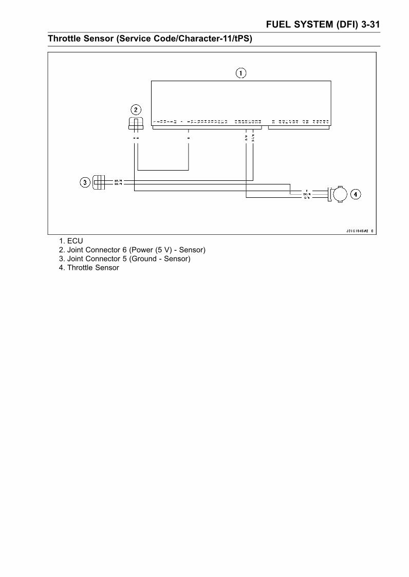
FUEL SYSTEM (DFI) 3-31Throttle Sensor (Service Code/Character-11/tPS)
1. ECU2. Joint Connector 6 (Power (5 V) - Sensor)3. Joint Connector 5 (Ground - Sensor)4. Throttle Sensor
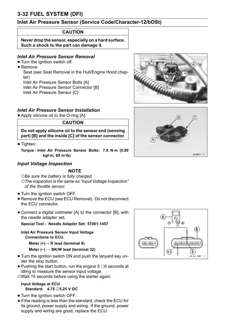
3-32 FUEL SYSTEM (DFI)Inlet Air Pressure Sensor (Service Code/Character-12/bOSt)
CAUTIONNever drop the sensor, especially on a hard surface.Such a shock to the part can damage it.
Inlet Air Pressure Sensor Removal•Turn the ignition switch off.• Remove:Seat (see Seat Removal in the Hull/Engine Hood chap-ter)Inlet Air Pressure Sensor Bolts [A]Inlet Air Pressure Sensor Connector [B]Inlet Air Pressure Sensor [C]
Inlet Air Pressure Sensor Installation•Apply silicone oil to the O-ring [A].
CAUTIONDo not apply silicone oil to the sensor end (sensingpart) [B] and the inside [C] of the sensor connector.
•Tighten:Torque - Inlet Air Pressure Sensor Bolts: 7.8 N·m (0.80
kgf·m, 69 in·lb)
Input Voltage InspectionNOTE
Be sure the battery is fully charged.The inspection is the same as “Input Voltage Inspection”of the throttle sensor.
•Turn the ignition switch OFF.•Remove the ECU (see ECURemoval). Do not disconnectthe ECU connector.
• Connect a digital voltmeter [A] to the connector [B], withthe needle adapter set.Special Tool - Needle Adapter Set: 57001-1457
Inlet Air Pressure Sensor Input VoltageConnections to ECUMeter (+)→ R lead (terminal 9)Meter (–) → BK/W lead (terminal 32)
•Turn the ignition switch ON and push the lanyard key un-der the stop button.• Pushing the start button, run the engine 5 ∼ 6 seconds atidling to measure the sensor input voltage.Wait 15 seconds before using the starter again.Input Voltage at ECUStandard: 4.75 ∼ 5.25 V DC
•Turn the ignition switch OFF.If the reading is less than the standard, check the ECU forits ground, power supply and wiring. If the ground, powersupply and wiring are good, replace the ECU.

FUEL SYSTEM (DFI) 3-33Inlet Air Pressure Sensor (Service Code/Character-12/bOSt)
If the reading is within the standard range, and check theinput voltage at the sensor connector.• Disconnect the inlet air pressure sensor connector andconnect the harness adapter [A] between the harnessconnector and inlet air pressure sensor connector.• Connect a digital meter to the harness adapter leads.[B] Inlet Air Pressure SensorSpecial Tool - Sensor Harness Adapter: 57001-1561
Inlet Air Pressure Sensor Input VoltageConnections to SensorMeter (+) → R lead [C]Meter (–) → BK/W lead [D]
•Turn the ignition switch ON and push the lanyard key un-der the stop button.• Pushing the start button, run the engine 5 ∼ 6 seconds atidling to measure the sensor input voltage.Wait 15 seconds before using the starter again.Input Voltage at Sensor ConnectorStandard: 4.75 ∼ 5.25 V DC
•Turn the ignition switch OFF.If the reading is out of the standard range, check thewiring (see Wiring Diagram in this section).If the reading is good, the input voltage is normal. Checkthe output voltage.
Output Voltage Inspection•Measure the output voltage at the ECU in the same wayas input voltage inspection. Note the following.
Inlet Air Pressure Sensor Output VoltageConnections to ECUMeter (+) → G/R lead (terminal 23)Meter (–) → BK/W lead (terminal 32)
Output Voltage at ECUUsable Range: 3.75 ∼ 4.25 V DC at the standard
atmospheric pressure (101.32 kPa, 76cmHg absolute)
NOTEThe output voltage changes according to the local at-mospheric pressure.The vacuum sensor output voltage is based on a nearlyperfect vacuum in the small chamber of the sensor. So,the sensor indicates absolute vacuum pressure.
If the output voltage is within the usable range, checkthe ECU for its ground, power supply and wiring. If theground, power supply and wiring are good, replace theECU.
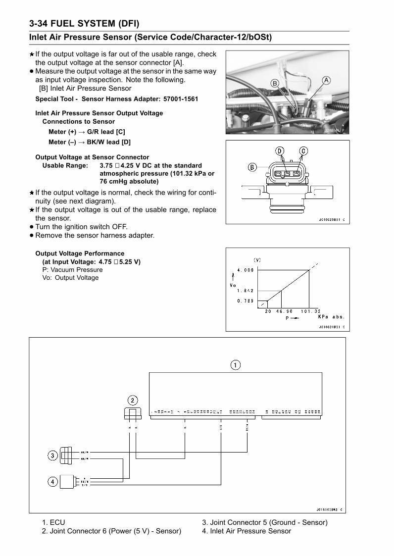
3-34 FUEL SYSTEM (DFI)Inlet Air Pressure Sensor (Service Code/Character-12/bOSt)
If the output voltage is far out of the usable range, checkthe output voltage at the sensor connector [A].•Measure the output voltage at the sensor in the same wayas input voltage inspection. Note the following.[B] Inlet Air Pressure SensorSpecial Tool - Sensor Harness Adapter: 57001-1561
Inlet Air Pressure Sensor Output VoltageConnections to SensorMeter (+) → G/R lead [C]Meter (–) → BK/W lead [D]
Output Voltage at Sensor ConnectorUsable Range: 3.75 ∼ 4.25 V DC at the standard
atmospheric pressure (101.32 kPa or76 cmHg absolute)
If the output voltage is normal, check the wiring for conti-nuity (see next diagram).If the output voltage is out of the usable range, replacethe sensor.• Turn the ignition switch OFF.•Remove the sensor harness adapter.Output Voltage Performance(at Input Voltage: 4.75 ∼ 5.25 V)P: Vacuum PressureVo: Output Voltage
1. ECU2. Joint Connector 6 (Power (5 V) - Sensor)
3. Joint Connector 5 (Ground - Sensor)4. Inlet Air Pressure Sensor

FUEL SYSTEM (DFI) 3-35Inlet Air Temperature Sensor (Service Code/Character-13/AIrt)
Inlet Air Temperature Removal/InstallationCAUTION
Never drop the sensor, especially on a hard surface.Such a shock to the sensor can damage it.
•Remove the air filter (see Air Filter Removal).• Disconnect the connector [A] from the inlet air tempera-ture sensor.• Remove the inlet air temperature sensor [B] and washer.• Install the inlet air temperature sensor and washer [A].• Tighten:Torque - Inlet Air Temperature Sensor: 20 N·m (2.0 kgf·m,
14 ft·lb)
Output Voltage InspectionNOTE
Be sure the battery is fully charged.•Remove the ECU (see ECURemoval). Do not disconnectthe ECU connector.• Connect a digital voltmeter to the ECU connector, usingneedle adapter set.Special Tool - Needle Adapter Set: 57001-1457
Inlet Air Temperature Sensor Output VoltageConnections to ECU ConnectorMeter (+) → R/BL lead (terminal 28)Meter (–) → BK/W lead (terminal 32)
•Turn the ignition switch ON and push the lanyard key un-der the stop button.• Pushing the start button, run the engine 5 ∼ 6 seconds atidling to measure the sensor output voltage.Wait 15 seconds before using the starter again.Output Voltage at ECUStandard: about 2.3 ∼ 2.6 V at inlet air temperature
20°C (68°F)
NOTEThe output voltage changes according to the inlet airtemperature.
•Turn the ignition switch OFF.

3-36 FUEL SYSTEM (DFI)Inlet Air Temperature Sensor (Service Code/Character-13/AIrt)
If the output voltage is out of the specified, check the ECUfor its ground, and power supply (see ECU Power SupplyInspection). If the ground and power supply are good,replace the ECU.If the output voltage is far out of the specified, check thewiring (see next diagram).• Remove the needle adapter set, and apply siliconesealant to the seals of the connector for waterproofing.Silicone Sealant (Kawasaki Bond: 56019-120) -Sealsof ECU Connectors
If the wiring is good, check the sensor resistance.
Sensor Resistance Inspection•Remove the inlet air temperature sensor (see Inlet AirTemperature Sensor Removal).• Suspend the sensor [A] in a container of machine oil sothat the heat-sensitive portion and threaded portion aresubmerged.• Suspend a thermometer [B] with the heat-sensitive por-tion [C] located in almost the same depth with the sensor.
NOTEThe sensor and thermometer must not touch the con-tainer side or bottom.
•Place the container over a source of heat and graduallyraise the temperature of the oil while stirring the oil gentlyfor even temperature.• Using a digital meter, measure the internal resistanceof the sensor across the terminals at the temperaturesshown in the table.
Inlet Air Temperature Sensor ResistanceStandard: 5.4 ∼ 6.6 kΩ at 0°C (32°F)
2.26 ∼ 2.86 kΩ at 20°C (68°F)0.29 ∼ 0.39 kΩ at 80°C (176°F)
If themeasurement is out of the range, replace the sensor.If the measurement is within the specified, replace theECU.

FUEL SYSTEM (DFI) 3-37Inlet Air Temperature Sensor (Service Code/Character-13/AIrt)
1. ECU2. Joint Connector 5 (Ground - Sensor)3. Inlet Air Temperature Sensor

3-38 FUEL SYSTEM (DFI)Water Temperature Sensor (Service Code/Character-14/AqUt)
Water Temperature Sensor Removal/InstallationCAUTION
Never drop the sensor, especially on a hard surface.Such a shock to the sensor can damage it.
•Disconnect the sensor connector [A], and unscrew thewater temperature sensor [B].
•When installing the water temperature sensor, remove theexhaust manifold for the engine oil filling in the hollow ofthe exhaust manifold.
• Fill the hollow of the exhaust manifold [A] with the engineoil (10W-30) [B] as shown, before installing the water tem-perature sensor [C].[D] 5 mm (0.2 in.)• Tighten:Torque - Water Temperature Sensor: 15 N·m (1.5 kgf·m, 11
ft·lb)
Output Voltage InspectionNOTE
Be sure the battery is fully charged.•Remove the ECU (see ECURemoval). Do not disconnectthe connector.

FUEL SYSTEM (DFI) 3-39Water Temperature Sensor (Service Code/Character-14/AqUt)
•Connect a digital voltmeter [A] to the ECU connector [B],with the needle adapter set.Special Tool - Needle Adapter Set: 57001-1457
Water Temperature Sensor Output VoltageConnections to ECUMeter (+) → G/Y lead (terminal 11)Meter (–) → BK/W lead (terminal 32)
•Turn the ignition switch ON and push the lanyard key un-der the stop button.• Pushing the start button, run the engine 5 ∼ 6 seconds atidling to measure the sensor output voltage.Wait 15 seconds before using the starter again.Output Voltage at ECUStandard: about 3 ∼ 4 V at 20°C (68°F)
NOTEThe output voltage changes according to the coolanttemperature in the engine.
•Turn the ignition switch OFF.If the output voltage is out of the specified, check the ECUfor its ground, and power supply (see ECU Power SupplyInspection). If the ground and power supply are good,replace the ECU.If the output voltage is far out of the specified (e.g. whenthe wiring is open, the voltage is about 5 V), check thewiring (see next diagram).If the wiring is good, check the water temperature sensorresistance.• Remove the needle adapter set, and apply siliconesealant to the seals of the connector for waterproofing.Silicone Sealant (Kawasaki Bond: 56019-120) -Sealsof ECU Connectors

3-40 FUEL SYSTEM (DFI)Water Temperature Sensor (Service Code/Character-14/AqUt)
1. ECU2. Joint Connector 5 (Ground - Sensor)3. Water Temperature Sensor
Sensor Resistance Inspection•Remove the water temperature sensor (see Water Tem-perature Sensor Removal/Installation).• Refer to Electrical System chapter for water temperaturesensor inspection.

FUEL SYSTEM (DFI) 3-41Crankshaft Sensor (Service Code/Character-21/CrAg)
Crankshaft Sensor Removal/Installation•See the Ignition System section in Electrical Systemchapter.
Crankshaft Sensor InspectionThe crankshaft have no power source, and when the en-gine stops, the crankshaft generates no signals.• Crank the engine and measure the peak voltage of thecrankshaft sensor (see Ignition System section in theElectrical System chapter) in order to check the sensor.• Check the wiring for continuity, using the following dia-gram.
1. ECU2. Crankshaft Sensor

3-42 FUEL SYSTEM (DFI)Camshaft Position Sensor (Service Code/Character-23/CAA1)
Camshaft Position Sensor Removal/InstallationThe camshaft position sensor detects the position of the
camshaft, and distinguishes the cylinder.• See Ignition System section in Electric System chapter.Camshaft Position Sensor InspectionThe camshaft position sensor have no power source, andwhen the engine stops, the camshaft position sensor gen-erates no signal.• Crank the engine and measure the peak voltage of thecamshaft position sensor (see Ignition System section inthe Electrical System chapter) in order to check the sen-sor.• Check the wiring for continuity, using the following dia-gram.
1. ECU2. Camshaft Position Sensor (Exhaust)3. Joint Connector 9 (Ground Control)

FUEL SYSTEM (DFI) 3-43Vehicle-down Sensor (Service Code/Character-31/dOS)
This sensor has a weight [A] with two magnets inside, andsends a signal to the ECU. But when the watercraft banks110 ∼ 130° or more to either side (in fact falls down), theweight turns and shuts off the signal. The ECU senses thischange, and stops the fuel pump, the fuel injectors, and theignition system.Hall IC [B]
Vehicle-down Sensor Connector [A]Ground Terminal BK/W [B]Output Terminal BL/W [C]Power Source Terminal R/G [D]
Vehicle-down Sensor RemovalCAUTION
Never drop the down-sensor, especially on a hardsurface. Such a shock to the sensor can damage it.
•Remove:Seat (see Hull/Engine Hood chapter)Front Storage Pocket (see Hull/Engine Hood chapter)Bracket Bolts [A] and Washers
•Remove:Vehicle-down Sensor Connector [A]Screws [B]Vehicle-down Sensor [C]
Vehicle-down Sensor Installation•The UP mark [A] of the sensor should face upward.
WARNINGIncorrect installation of the vehicle-down sensorcould cause sudden loss of engine power. Therider could lose balance during certain riding situ-ations, like leaning over in a turn, with the potentialfor an accident resulting in injury or death. Ensurethat the down sensor is held in place by the sensorbrackets.
•Tighten:Torque - Vehicle-down Sensor Mounting Screws: 1.5 N·m
(0.15 kgf·m, 13 in·lb)

3-44 FUEL SYSTEM (DFI)Vehicle-down Sensor (Service Code/Character-31/dOS)
Vehicle-down Sensor InspectionNOTE
Be sure the battery is fully charged.•Remove the seat (see Seat Removal in the Hull/EngineHood chapter).
• Connect a digital volt meter [A] to the connector [B] of thevehicle-down sensor lead with the needle adapter set [C].Special Tool - Needle Adapter Set: 57001-1457
Vehicle-down Sensor Power Source VoltageConnections to SensorMeter (+) → R/G lead [D]Meter (–) → BK/W lead [E]
•Turn the ignition switch ON and push the lanyard key un-der the stop button.• Pushing the start button, run the engine 5 ∼ 6 seconds atidling to measure the sensor power sours voltage.Wait 15 seconds before using the starter again.Power Source Voltage at SensorStandard: 4.75 ∼ 5.25 V
•Turn the ignition switch OFF.If there is no standard voltage, check the following:Battery (see Electrical System chapter)Main Fuse 20 AWiring for Vehicle-down Sensor Power Source (see nextdiagram)If the power source is normal, check the output voltage.
• Turn the ignition switch OFF.•Remove the vehicle-down sensor. Do not disconnect theconnector.• Connect a digital volt meter [A] to the connector, with nee-dle adapter set [B].Special Tool - Needle Adapter Set: 57001-1457
Vehicle-down Sensor Output VoltageConnections to SensorMeter (+) → BL/W lead [D]Meter (–) → BK/W lead [E]
•Hold the sensor vertically.• Turn the ignition switch ON and push the lanyard key un-der the stop button.• Pushing the start button, run the engine 5 ∼ 6 seconds atidling to measure the sensor output voltage.Tilt the sensor 110 ∼ 130° or more [C] right or left, thenhold the sensor and measure the output voltage.Wait 15 seconds before using the starter again.Output Voltage at SensorStandard: with sensor tilted 110 ∼ 130° or more right
or left: 0.65 ∼ 1.35 Vwith sensor arrow mark pointed up: 3.55∼ 4.45 V

FUEL SYSTEM (DFI) 3-45Vehicle-down Sensor (Service Code/Character-31/dOS)
•Turn the ignition switch OFF.•Remove the needle adapter set, and apply siliconesealant to the seals of the connector for waterproofing.Silicone Sealant (Kawasaki Bond: 56019-120) -Seals ofVehicle-down Sensor Connector
If the output voltage is normal, the wiring is suspect.Check the wiring.If the wiring is good, check the ECU for its ground andpower supply (see ECU Power Supply Inspection). If theground and power supply are good, replace the ECU.If the output voltage is out of the specified, replace thevehicle-down sensor.
1. ECU2. Joint Connector 6 (Power (5 V) - Sensor)3. Joint Connector 5 (Ground - Sensor)4. Vehicle Down Sensor

3-46 FUEL SYSTEM (DFI)Immobilizer Amplifier (Service Code/Character-35/IdA)
Amplifier Input Voltage InspectionNOTE
Be sure the battery is fully charged.•Turn the ignition switch OFF.•Remove the front access cover (see Front Access CoverRemoval in the Hull/Engine Hood chapter).
• Connect a digital meter to the ignition switch connector[A], using the needle adapter set.Special Tool - Needle Adapter Set: 57001-1457
Ignition Switch Input VoltageConnections to ConnectorMeter (+) → R leadMeter (–) →BK lead
•Measure the input voltage with the engine stopped, andwith the connector joined.• Turn the ignition switch ON.Input VoltageStandard: Battery Voltage
•Turn the ignition switch OFF.If the reading is out of the range, check the wiring (seewiring diagram in next section).If the reading is good, replace the ignition switch (seeImmobilizer System Parts Replacement in the ElectricalSystem chapter).

FUEL SYSTEM (DFI) 3-47Key Collation Error (Service Code/Character-36/IdEr)
•This code appears in the following conditions.The transponder [A] in the FPO mode and/or SLO modekey is malfunction.When the spare key of unregistration is used.• Therefore, the service code 36 will disappear when theabove issue is solved.
User Key Inspection•Register the user key correctly (see Key Registration inthe Electrical System chapter).If the service code 36 appears again, the transponder inthe key is malfunction, replace it.
Immobilizer System Circuit
1. Ignition Switch (Immobilizer Amplifier)2. Joint Connector 13. Joint Connector 24. System Relay5. Joint Connector 7
6. ECU7. Main Fuse 20 A8. Battery9. Joint Connector 1210. Joint Connector 15
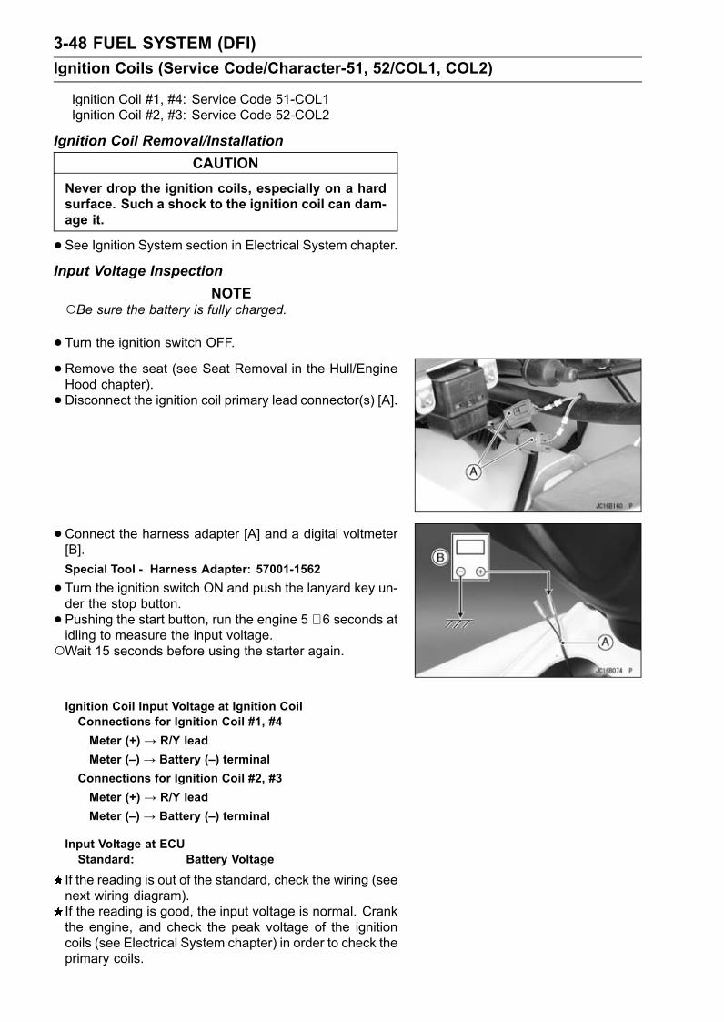
3-48 FUEL SYSTEM (DFI)Ignition Coils (Service Code/Character-51, 52/COL1, COL2)
Ignition Coil #1, #4: Service Code 51-COL1Ignition Coil #2, #3: Service Code 52-COL2
Ignition Coil Removal/InstallationCAUTION
Never drop the ignition coils, especially on a hardsurface. Such a shock to the ignition coil can dam-age it.
•See Ignition System section in Electrical System chapter.Input Voltage Inspection
NOTEBe sure the battery is fully charged.
•Turn the ignition switch OFF.•Remove the seat (see Seat Removal in the Hull/EngineHood chapter).• Disconnect the ignition coil primary lead connector(s) [A].
• Connect the harness adapter [A] and a digital voltmeter[B].Special Tool - Harness Adapter: 57001-1562
•Turn the ignition switch ON and push the lanyard key un-der the stop button.• Pushing the start button, run the engine 5 ∼ 6 seconds atidling to measure the input voltage.Wait 15 seconds before using the starter again.
Ignition Coil Input Voltage at Ignition CoilConnections for Ignition Coil #1, #4Meter (+) → R/Y leadMeter (–) → Battery (–) terminal
Connections for Ignition Coil #2, #3Meter (+) → R/Y leadMeter (–) → Battery (–) terminal
Input Voltage at ECUStandard: Battery Voltage
If the reading is out of the standard, check the wiring (seenext wiring diagram).If the reading is good, the input voltage is normal. Crankthe engine, and check the peak voltage of the ignitioncoils (see Electrical System chapter) in order to check theprimary coils.

FUEL SYSTEM (DFI) 3-49Ignition Coils (Service Code/Character-51, 52/COL1, COL2)
1. ECU2. Joint Connector 8 (Vcc)3. Joint Connector 7 (Vcc)4. System Relay5. Main (ECU) Relay6. Joint Connector 27. Joint Connector 18. Joint Connector 11 (Ground)9. Joint Connector 12 (Ground)10. Battery11. Main Fuse 20 A12. Spark Plugs13. Ignition Coils14. Joint Connector 10 (Ignition Coil (12 V))15. Joint Connector 9 (Ground Control)

3-50 FUEL SYSTEM (DFI)Engine Overheating (Service Code/Character-71/HEAt)
• If the service code is displayed, check the doubtful parts referring to the following table.Possible Causes Action (Chapter)
Water passage clogged, loosened or damaged Inspect (see 9 chapter)Incorrect engine oil level Inspect (see 4 chapter)Engine oil poor quality or incorrect Change (see 4 chapter)Water temperature sensor broken Inspect (see 3 and 14 chapters)Jet pump or impeller damaged Inspect (see 11 chapter)Oil cooler clogged Clean (see 4 chapter)Carbon build-up on combustion chamber Clean (see 6 chapter)

FUEL SYSTEM (DFI) 3-51Low Engine Oil Pressure (Service Code/Character-72/OILP)
• If the service code is displayed, check the doubtful parts referring to the following table.Possible Causes Action (Chapter)
Oil leak Inspect (see 4 chapter)Engine oil level too low Inspect (see 4 chapter)Engine oil viscosity too low Inspect (see 4 chapter)Oil filter clogged Clean (see 4 chapter)Oil pressure switch damaged Inspect (see 3 and 14 chapters)Oil cooler clogged Inspect (see 4 chapter)Camshaft bearing worn Inspect (see 6 chapter)Crankshaft bearing worn Inspect (see 8 chapter)Oil pressure relief valve stuck open Change (see 4 chapter)Oil pump damaged Change (see 4 chapter)Oil screen clogged Clean (see 4 chapter)O-ring at the oil passage in the crankcase damaged Change (see 4 chapter)

3-52 FUEL SYSTEM (DFI)Oil Temperature Sensor (Service Code/Character-73/OILt)
Oil Temperature Sensor Removal/InstallationCAUTION
Never drop the sensor, especially on a hard surface.Such a shock to the sensor can damage it.
•Remove:Seat (see Seat Removal in the Hull/Engine Hood chap-ter)Oil Temperature Sensor [A]
• Fill the hollow of the oil pan [A] with the specified siliconegrease [B] as shown, before installing the oil temperaturesensor [C].[D] 5 mm (0.2 in.)Silicone Grease-Kawasaki Bond: 92137-1002
•Tighten:Torque - Oil Temperature Sensor: 15 N·m (1.5 kgf·m, 11
ft·lb)
Output Voltage InspectionNOTE
Be sure the battery is fully charged.•Remove the ECU (see this chapter). Do not disconnectthe connector.
• Connect a digital voltmeter [A] to the ECU connector [B],with the needle adapter set.Special Tool - Needle Adapter Set: 57001-1457
Water Temperature Sensor Output VoltageConnections to ECUMeter (+) → Y lead (terminal 13)Meter (–) → BK/W lead (terminal 32)
•Turn the ignition switch ON and push the lanyard key un-der the stop button.• Pushing the start button, run the engine 5 ∼ 6 seconds atidling to measure the sensor output voltage.Wait 15 seconds before using the starter again.Output Voltage at ECUStandard: about 3 ∼ 4 V at 20°C (68°F)
NOTEThe output voltage changes according to the oil temper-ature in the engine.

FUEL SYSTEM (DFI) 3-53Oil Temperature Sensor (Service Code/Character-73/OILt)
•Turn the ignition switch OFF.If the output voltage is out of the specified, check the ECUfor its ground, and power supply (see ECU Power SupplyInspection). If the ground and power supply are good,replace the ECU.If the output voltage is far out of the specified (e.g. whenthe wiring is open, the voltage is about 5 V), check thewiring (see next diagram).If the wiring is good, check the oil temperature sensorresistance.• Remove the needle adapter set, and apply siliconesealant to the seals of the connector for waterproofing.Silicone Sealant (Kawasaki Bond: 56019-120) -Sealsof ECU Connectors
1. ECU2. Joint Connector 5 (Ground - Sensor)3. Oil Temperature Sensor
Sensor Resistance Inspection•Remove the oil temperature sensor (see Oil TemperatureSensor Removal/Installation).• Refer to Electrical System chapter for oil temperature sen-sor inspection.
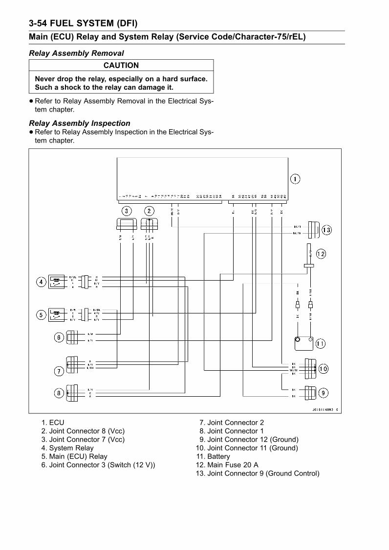
3-54 FUEL SYSTEM (DFI)Main (ECU) Relay and System Relay (Service Code/Character-75/rEL)
Relay Assembly RemovalCAUTION
Never drop the relay, especially on a hard surface.Such a shock to the relay can damage it.
•Refer to Relay Assembly Removal in the Electrical Sys-tem chapter.
Relay Assembly Inspection•Refer to Relay Assembly Inspection in the Electrical Sys-tem chapter.
1. ECU2. Joint Connector 8 (Vcc)3. Joint Connector 7 (Vcc)4. System Relay5. Main (ECU) Relay6. Joint Connector 3 (Switch (12 V))
7. Joint Connector 28. Joint Connector 19. Joint Connector 12 (Ground)10. Joint Connector 11 (Ground)11. Battery12. Main Fuse 20 A13. Joint Connector 9 (Ground Control)

FUEL SYSTEM (DFI) 3-55Engine Oil Overheating (Service Code/Character-76/OILH)
• If the service code is displayed, check the doubtful parts referring to the following table.Possible causes Action (Chapter)
Incorrect engine oil level Inspect (see 4 chapter)Engine oil poor quality or incorrect Change (see 4 chapter)Oil temperature sensor broken Inspect (see 3 and 14 chapters)Oil cooler clogged Clean (see 4 chapter)Oil pump malfunction Inspect (see 4 chapter)Relief valve malfunction Inspect (see 4 chapter)Water passage clogged, loosened or damaged Inspect (see 9 chapter)Weeds or debris in jet pump Inspect (see 11 chapter)

3-56 FUEL SYSTEM (DFI)Fuel Injectors
Fuel Injector RemovalWARNING
Gasoline is extremely flammable and can be ex-plosive under certain conditions. Turn the ignitionswitch OFF. Disconnect the battery (–) cable ter-minal. Do not smoke. Make sure the area iswell-ventilated and free from any source of flameor sparks; this includes any appliance with a pilotlight.Be prepared for fuel spillage: any spilled fuel mustbe completely wiped up immediately.
•Remove:Seat (see Hull/Engine Hood chapter)Fuel Hose (see Fuel Hose Removal)Delivery Pipe Mounting Bolts [A], Collars [B] and Clamps•Remove the delivery pipe assembly from the cylinderhead.
• Push the lock [A] and disconnect the injector connectors.• Remove the fuel injectors [B].CAUTION
Never drop the injector, especially on a hard sur-face. Such a shock to the injector can damage it.
Fuel Injector Installation•Replace the O-rings [A] of the injectors with new ones.• Apply grease to the O-rings.• Insert the injectors into the delivery pipe and confirmwhether they turn smoothly or not.

FUEL SYSTEM (DFI) 3-57Fuel Injectors
•Replace the seals [A] with new ones.• Apply grease to the inside and outside of seals.
• Install:Delivery Pipe AssemblyCollars• Install the clamps [A] as shown.• Tighten:Torque - Delivery PipeMounting Bolts: 7.8 N·m (0.80 kgf·m,
69 in·lb)
• Install the fuel hose (see Fuel Hose Installation).• Route the fuel hose correctly (see Cable, Wire, and HoseRouting section in Appendix chapter).
Audible Inspection•Start the engine.• Apply the tip of a screwdriver [A] to the injector [B]. Putthe grip end onto your ear, and listen whether the injectoris clicking or not.• A sound scope can also be used.• Do the same for the other injector.If all the injectors click at a regular intervals, the injectorsare good.The click interval becomes shorter as the engine speedrises.If either injector doesn’t click, perform the “Injector SignalTest” for injector operation.
Injector Signal Test•Prepare four test lights set with male terminals as shown.Rating of Bulb [A]: 12 V, 3 ∼ 3.4 WTerminal Width [B]: 1.8 mm (0.07 in.)Terminal Thickness [C]: 0.8 mm (0.03 in.)
CAUTIONDo not use larger terminals than specified above. Alarger terminal could damage the injector main har-ness connector (female), leading to harness repairor replacement.

3-58 FUEL SYSTEM (DFI)Fuel Injectors
•Remove connectors for injector [A].• Connect each test light set [B] to the injector harness con-nector [C].• Turn the ignition switch ON.•While cranking the engine with the starter motor, watchthe test lights.If the test lights flicker at regular intervals, the injectorcircuit in the ECU, and the wiring are good. Perform the“Injector Resistance Inspection”.
Injector signals can be also confirmed by connecting thehand tester (× 10 V AC) instead of the test light set tothe injector harness (female) connector. Crank the en-gine with the starter motor, and check to see if the handoscillates at regular intervals.Special Tool - Hand Tester: 57001-1394If the test light doesn’t flicker (or the test hand doesn’toscillates), check the wiring and connectors again. If thewiring is good, check the injector voltage.
Injector Resistance Inspection•Remove the delivery pipe assembly.• Disconnect the connector from the injector [A].•Measure the injector resistance with the hand tester [B].Special Tool - Hand Tester: 57001-1394
Injector ResistanceStandard: about 11.7 ∼ 12.3 Ω @20°C (68°F)
If the reading is out of the range, perform the “Injector UnitTest”.If the reading is normal, perform the “Injector Unit Test”for confirmation.
Injector Unit Test•Use two leads [A] and the same test light set [B] as in“Injector Signal Test”.Rating of Bulb [C]: 12 V, 3 ∼ 3.4 W12 V Battery [D]
CAUTIONBe sure to connect the bulb in series. The bulbworks as a current limiter to protect the solenoidin the injector from excessive current.
•Connect the test light set to the injector [E] as shown.•Open and connect [F] the end of the lead to the battery(–) terminal repeatedly. The injector should click.If the injector does not click, replace the injector.

FUEL SYSTEM (DFI) 3-59Fuel Injectors
Injector Voltage Inspection•Turn the ignition switch OFF.•Connect a digital voltmeter [A] to the connector [B], withthe needle adapter set.Special Tool - Needle Adapter Set: 57001-1457
Injector Power Source VoltageConnector to Injector #1, #2, #3, #4Meter (+) → R/Y leadMeter (–) → Battery (–) Terminal
•Turn the ignition switch ON and push the lanyard key un-der the stop button.• Pushing the start button, run the engine 5 ∼ 6 seconds atidling to measure the injector power source voltage.Wait 15 seconds before using the starter again.Power Source Voltage at Injector ConnectorStandard: Battery Voltage
If the power source voltage is less than standard, checkthe wiring (see Wiring Diagram in this section), relay(Main Relay Inspection) and ECU power source (seeECU Power Supply Inspection).
• Remove the ECU. Do not disconnect the connector.• Connect a digital voltmeter [A] to the connector [B], withthe needle adapter set [C].Special Tool - Needle Adapter Set: 57001-1457
Injector Output VoltageConnections to Injector #1Meter (+) → PU lead (terminal 42)Meter (–) → Battery (–) Terminal
Connections to Injector #2Meter (+) → O lead (terminal 51)Meter (–) → Battery (–) Terminal
Connections to Injector #3Meter (+) → BR lead (terminal 38)Meter (–) → Battery (–) Terminal
Connections to Injector #4Meter (+) → BL/Y lead (terminal 47)Meter (–) → Battery (–) Terminal
•Turn the ignition switch ON and push the lanyard key un-der the stop button.• Pushing the start button, run the engine 5 ∼ 6 seconds atidling to measure the output voltage.Wait 15 seconds before using the starter again.Output Voltage at Injector ConnectorStandard: about 9 V or more
If the output voltage is out of the standard, replace theECU.

3-60 FUEL SYSTEM (DFI)Fuel Injectors
Injector Fuel Line Inspection•Check the injector fuel line for leakage as follows:Connect a commercially available vacuum/pressurepump [A] to the supply joint of the delivery pipe [B] withthe fuel hose [C] (both ends connected with the clamps[D]) as shown.Plug the return joint of the delivery pipe with a rubber plug[E].Tighten the clamp [F].Apply soap and water solution to the areas [G] as shown.Watching the pressure gauge, squeeze the pump lever[H], and build up the pressure until the pressure reachesthe maximum pressure.
Fuel Line Maximum PressureStandard: 300 kPa (3.06 kgf/cm², 44 psi)
CAUTIONDuring pressure testing, do not exceed the maxi-mum pressure for which the system is designed.
Watch the gauge for at least 6 seconds.If the pressure holds steady, the system is good.If the pressure drops at once, or if bubbles are found inthe area, the line is leaking. Replace the delivery pipe,injectors and related parts.• Repeat the leak test, and check the fuel line for no leak-age.• Run the hoses correctly (seeCable, Wire, and HoseRout-ing section in Appendix chapter).
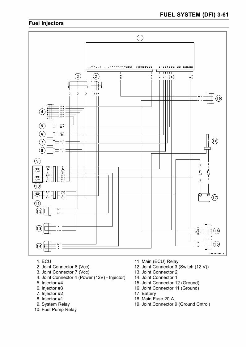
FUEL SYSTEM (DFI) 3-61Fuel Injectors
1. ECU2. Joint Connector 8 (Vcc)3. Joint Connector 7 (Vcc)4. Joint Connector 4 (Power (12V) - Injector)5. Injector #46. Injector #37. Injector #28. Injector #19. System Relay10. Fuel Pump Relay
11. Main (ECU) Relay12. Joint Connector 3 (Switch (12 V))13. Joint Connector 214. Joint Connector 115. Joint Connector 12 (Ground)16. Joint Connector 11 (Ground)17. Battery18. Main Fuse 20 A19. Joint Connector 9 (Ground Cntrol)

3-62 FUEL SYSTEM (DFI)ECU
CAUTIONNever drop the ECU, especially on a hard surface.Such a shock to the ECU can damage it.
ECU Removal•Remove:Seat (see Seat Removal in the Hull/Engine Hood chap-ter)Front Access Cover (see Front Access Cover Re-moval/Installation in the Hull/Engine Hood chapter)ECU Lead ConnectorMounting Bolts [A]ECU [B]
ECU Installation•Connect the ECU connector and install it.• Apply a non-permanent locking agent to the bolts andtighten them.Torque - ECU Mounting Bolts: 8.8 N·m (0.90 kgf·m, 78 in·lb)
ECU Power Supply Inspection•Visually inspect the terminals [A] of the ECU connectors.If the connector is clogged with mud or dust, blow it offwith compressed air.Replace the main harness if the terminals of the main har-ness connector is cracked, bent, or otherwise damaged.Replace the ECU if the terminals of the ECU connector iscracked, bent, or otherwise damaged.
•With the ECU connector [A] connected, check the follow-ing ground lead for continuity with the ignition switch OFF,using a tester and needle adapter set.[B] Battery[C] TesterSpecial Tool - Needle Adapter Set: 57001-1457
ECU Grounding Inspection15 (BK/R), 39, 48 (BK)Terminal
←→ Battery (–) Terminal: 0 Ω
Engine Ground ←→ Battery (–) Terminal: 0 Ω
If no continuity, check the connector, the engine groundlead, or main harness, and repair or replace them if nec-essary.
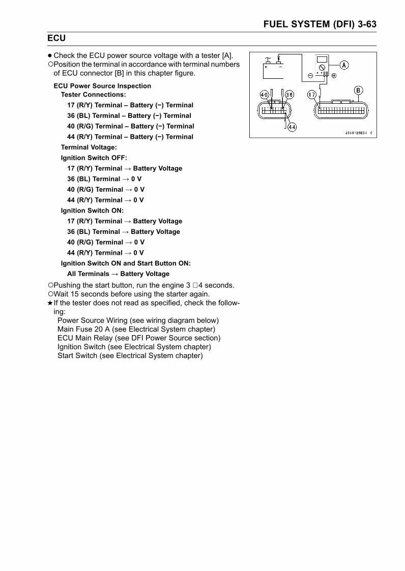
FUEL SYSTEM (DFI) 3-63ECU
•Check the ECU power source voltage with a tester [A].Position the terminal in accordance with terminal numbersof ECU connector [B] in this chapter figure.
ECU Power Source InspectionTester Connections:17 (R/Y) Terminal – Battery (−) Terminal36 (BL) Terminal – Battery (−) Terminal40 (R/G) Terminal – Battery (−) Terminal44 (R/Y) Terminal – Battery (−) Terminal
Terminal Voltage:Ignition Switch OFF:17 (R/Y) Terminal → Battery Voltage36 (BL) Terminal → 0 V40 (R/G) Terminal → 0 V44 (R/Y) Terminal → 0 V
Ignition Switch ON:17 (R/Y) Terminal → Battery Voltage36 (BL) Terminal → Battery Voltage40 (R/G) Terminal → 0 V44 (R/Y) Terminal → 0 V
Ignition Switch ON and Start Button ON:All Terminals → Battery Voltage
Pushing the start button, run the engine 3 ∼ 4 seconds.Wait 15 seconds before using the starter again.If the tester does not read as specified, check the follow-ing:Power Source Wiring (see wiring diagram below)Main Fuse 20 A (see Electrical System chapter)ECU Main Relay (see DFI Power Source section)Ignition Switch (see Electrical System chapter)Start Switch (see Electrical System chapter)

3-64 FUEL SYSTEM (DFI)ECU
ECU Power Source Circuit
1. ECU2. Joint Connector 8 (Vcc)3. Joint Connector 7 (Vcc)4. System Relay5. Main (ECU) Relay6. Joint Connector 3 (Switch (12 V))
7. Joint Connector 28. Joint Connector 19. Joint Connector 12 (Ground)10. Joint Connector 11 (Ground)11. Battery12. Main Fuse 20 A13. Joint Connector 9 (Ground Control)

FUEL SYSTEM (DFI) 3-65DFI Power Source
Main Fuse Inspection•Refer to the Electrical System chapter for the ECU FuseInspection.
Relay Assembly RemovalCAUTION
Never drop the relay, especially on a hard surface.Such a shock to the relay can damage it.
•Refer to the Relay Assembly Removal in the ElectricalSystem chapter.
Relay Assembly Inspection•Refer to the Relay Assembly Inspection in the ElectricalSystem chapter.

3-66 FUEL SYSTEM (DFI)Throttle Lever, Cable and Case
Free Play Inspection•Refer to Throttle Control System Inspection in the Peri-odic Maintenance chapter.
Throttle Cable Adjustment•Refer to Throttle Cable Adjustment in the Periodic Main-tenance chapter.
Throttle Case Removal/Disassembly•Unscrew the mounting screws [A] and remove the han-dlebar pad [B].• Remove the throttle case.Unscrew the throttle case mounting screws [C] separatethe case halves [D].
• Disconnect the throttle cable from the case.Slide the rubber boots [A] and rubber cap [B] out of theplace.Unscrew the throttle cable fitting nut [C].
Use a screw driver [A] to separate the tip [B] of the cableend from the case body.

FUEL SYSTEM (DFI) 3-67Throttle Lever, Cable and Case
•Disassemble the throttle case.Remove the circlip [A], flat washers [B], pin [C], throttlelever [D] and return spring [E] from the case [F].
Throttle Case Assembly/Installation• Insert the end of the return spring [A] in the throttle leverhole [B] and set the spring in the throttle case [C] asshown.• Install the control lever to the case.
• Lubricate the throttle cable before assembly/installation.• Apply water resistant grease to the tips of the throttle ca-ble end.• Pulling the throttle cable [A], position the tips [B] of thecable end as shown.• Tighten the cable fitting nut.
• Be sure the rubber cap [A] is in place on the throttle cablefitting nut end.• Cover the cable fitting nut [B] with the rubber boot [C].

3-68 FUEL SYSTEM (DFI)Throttle Lever, Cable and Case
•Tighten:Torque - Throttle Case Mounting Screws: 3.9 N·m (0.40
kgf·m, 34 in·lb)
•Swing the throttle lever so that the throttle valve is fullyopen.
WARNINGOperation with an improperly assembled throttlecase could result in an unsafe riding condition.
•Adjust the throttle cable (see Throttle Cable Adjustment).Throttle Cable Removal•Remove the engine hood (see Hull/Engine Hood chap-ter).• Remove the band [A] on the delivery pipe [B]
• Disconnect the throttle cable from the body assy.Slide out the rubber cap.Unscrew the adjuster locknut [A] and slide the cable fromthe bracket.
Slide the tip [A] of the cable lower end from the throttlepivot arm.
•Unscrew the mounting screws [A] and remove the han-dlebar pad [B].• Take out the inner pad

FUEL SYSTEM (DFI) 3-69Throttle Lever, Cable and Case
•Remove the throttle case (see Throttle Case Removal).• Slide the rubber boot out of the place.• Unscrew the throttle cable fitting nut.• Remove the upper end of the cable from the case.Use a screw driver [A] to separate the cable tip [B] fromthe throttle lever catch.
• Remove the steering cover (see Steering Removal inSteering chapter).• Unscrew the grommet mounting bolts [A] and pull out theplate [B] and grommet.• Cut off the clamps [C] and remove the protect tube [D].• Take the throttle cable [E] off the grommet.• Pull down the throttle cable.
Throttle Cable Installation• Lubricate the outside of the new cable with a penetratingrust inhibitor to ease cable installation.• Slide the tip [A] of the cable lower end on the throttle pivotarm [B].
• Tighten:Torque - Throttle Case Mounting Screws: 3.9 N·m (0.40
kgf·m, 34 in·lb)
•Route the following correctly (see Cable, Wire, and HoseRouting in Appendix chapter).Throttle CableSteering CableFuel Tank Vent HoseStart/Stop Switch LeadsBuzzer LeadsMultifunction Meter Leads• Adjust the following.Throttle Cable•Check that the throttle lever moves smoothly from fullopen to close, and the throttle closes quickly and com-pletely in all steering positions by return spring.If the throttle lever does not return properly, check thethrottle routing, cable adjustments, and cable damage.Then lubricate the throttle cable.• Run the engine at the idle speed, and turn the handlebarall the way to the right and left to ensure that the idle speeddoes not change.If the idle speed increases, check the throttle cable ad-justment and the cable routing.

3-70 FUEL SYSTEM (DFI)Throttle Lever, Cable and Case
Throttle Case and Cable Lubrication•Refer to the Lubrication in the Periodic Maintenancechapter.
Throttle Cable Inspection•Refer to the Lubrication in the Periodic Maintenancechapter.

FUEL SYSTEM (DFI) 3-71Air Filter
Air Filter Removal•Remove the seat (see Seat Removal in the Hull/EngineHood chapter).• Remove the rear grip plate (see Rear Grip Plate Removalin the Hull/Engine Hood chapter).• Disconnect the following from the air filter [A].Air Suction Valve Hose [B]Oil Separator Tank Hose [C]• Loosen the clamp on the inlet air duct.• Remove the air filter out of the engine compartment.
Air Filter Installation•Tighten:Torque - Air Filter Mounting Bolts: 9.8 N·m (1.0 kgf·m, 87
in·lb)
Air Filter Disassembly•Remove:Air Filter (see Air Filter Removal)Air Filter Bolts [A]
• Remove:Bolts [A]Flame Arrester [B]Hose [C]Duct [D]Air Filter Bracket Mounting Bolts [E]Air Filter Bracket [F]

3-72 FUEL SYSTEM (DFI)Air Filter
•Remove the air screen [A]
Air Filter Assembly•Visually inspect the seal [A] for damage.If necessary, replace it with a new one.• Install the flame arrester [B], hose [C] and duct [D] asshown.
• Install the air screen [A] aligning the marks [B].
• Apply a non-permanent locking agent to the air filterbracket mounting bolts and tighten them.Torque - Air Filter Bracket Mounting Bolts: 7.8 Nm (0.80
kgf·m, 69 in·lb)

FUEL SYSTEM (DFI) 3-73Throttle Body Assy
Idle Speed InspectionThe normal idle speed is controlled by the ECU (Elec-
tronic Control Unit).
Idle SpeedStandard: 1 300 ±100 r/min (rpm) -both in and out of
water
High Altitude Performance AdjustmentHigh altitude adjustment is not required as the ECU con-
trols the air/fuel mixture automatically.
Throttle Body Assy Removal•Remove:Seat (see Seat Removal in the Hull/Engine Hood chap-ter)Air Filter (see Air Filter Removal)Throttle Cable [A] (see Throttle Cable Removal)Air Inlet DuctISC (Idle Speed Controller) Connector [B]Throttle Sensor Connector [C]Throttle Body Assy Mounting Bolts [D]Throttle Body Assy [E]Gasket
Throttle Body Assy Installation• Install a new gasket.• Tighten:Torque - Throttle Body Assy Mounting Bolts: 20 N·m (2.0
kgf·m, 14 ft·lb)
• Install the throttle cable and adjust the free play.• Bind the harness [A] and connector in the band [B].• Route the harness [C] and tighten the band [D] correctly(see Appendix chapter).
Throttle Body Assy DisassemblyCAUTION
Do not disassemble or adjust, the air screw, throt-tle link mechanism and throttle body assy [A], be-cause they are adjusted or set surely at the man-ufacturer. Adjustment of these parts could resultin poor performance, requiring replacement of thethrottle body assy.

3-74 FUEL SYSTEM (DFI)Throttle Body Assy
Throttle Bore Cleaning•Remove the throttle body assy (see Throttle Body AssyRemoval).• Check the throttle bore [A] for carbon deposits by openingthe valve.If any carbon accumulates, wipe the carbon off the throttlebore and throttle valve, using a cotton pad.
CAUTIONDo not rub these surfaces hard and do not use acarburetor cleaning solution.
ISC (Idle Speed Controller) Removal/Installation•RemoveSeat (see Seat Removal in the Hull/Engine Hood chapter)Air Filter (see Air Filter Removal)Band [A]ISC connector [B]Stepping Motor Mounting Screws [C]Stepping Motor [D]ISC Actuator Mounting Bolts [E]ISC Actuator [F]
• Clean themating surface of throttle body and ISC actuator(stepping motor).• Replace the O-ring [A] with a new one.• Install the stepping motor [B] and tighten the screws [C].• Install the ISC actuator [D] and tighten the bolts [E].Torque - ISC Actuator Mounting Bolts: 4.9 N·m (0.50 kgf·m,
43 in·lb)
•Route the harness and tighten the bands correctly (seeAppendix chapter).• After installing the ISC actuator, check the Smart SteeringSystem Operation in the water.
ISC (Idle Speed Controller) Inspection•Check idle speed with a tachometer in the multifunctionmeter.With the engine idling, open and close the throttle lever.Idle SpeedStandard: 1 300 ±100 r/min (rpm) -both in and out of
water
If the idle speed is within the standard, the ISC operatesproperly.If the idle speed is out of the specified range, inspect theaudible operation.

FUEL SYSTEM (DFI) 3-75Throttle Body Assy
•Run the engine and then stop the engine.• Certain buzzing and humming sounds will be emitted fromthe ISC [A] after the engine stop.If the ISC sounds, inspect the ISC resistance.If the ISC does not sound, replace the steeping motor.
ISC Resistance Inspection•Remove:Air Filter (from the throttle body assy)ISC Connector [A] (disconnect)
•Measure the ISC resistance with the hand tester.Special Tool - Kawasaki Hand Tester: 57001-1394ISC [A]Rotor [B]
ISC ResistanceConnection: 1-2, 2-3, 4-5, 5-6 terminalsStandard: about 30 Ω (at 20°C)
Connection: 1-3, 4-6 terminalsStandard: about 60 Ω (at 20°C)
If the reading is out of the specified value, replace thesteeping motor.

3-76 FUEL SYSTEM (DFI)Inlet Manifold
Inlet Manifold Removal•Remove:Spark Plug Leads [A]Supply Fuel Hose [B] at Delivery Pipe (see Fuel HoseRemoval)Delivery Pipe Mounting Bolts, Collars and Clamps•Remove the bands [C] and disconnect the following con-nectors.Camshaft Position Sensor Connector [D]Crankshaft Sensor Connector• Disconnect:Throttle Cable Lower End (see Throttle Cable Removal)Throttle Sensor Connector on Throttle Body AssyISC (Idle Speed Controller) Connector on Throttle BodyAssyInlet Air Pressure Sensor Connector [E] on Inlet ManifoldInlet Air Temperature Sensor Connector on Inlet Mani-fold
•Disconnect the speed sensor connector [A].

FUEL SYSTEM (DFI) 3-77Inlet Manifold
•Disconnect the 3-pin stator coil leads connector [A].
• Pull the delivery pipe assembly [A] with the injectors outof the engine compartment.
• Unscrew the inlet manifold mounting bolts [A] and nuts[B].
• Remove the inlet manifold [A] with the throttle body assy[B].• Remove the throttle body assy from the inlet manifold (seeThrottle Body Assy Removal).
• Unscrew the inlet manifold plate bolts [A] and remove theplate [B] and gasket [C].• Remove:Inlet Air Temperature Sensor [D]Inlet Manifold Drain Plug [E]Inlet Air Pressure Sensor Bolts [F]Inlet Air Pressure Sensor [G]

3-78 FUEL SYSTEM (DFI)Inlet Manifold
Inlet Manifold Installation•Replace the inlet manifold plate gasket with a new one.• Tighten:Torque - Inlet Manifold Plate Bolts: 7.8 N·m (0.80 kgf·m, 69
in·lb)Inlet Manifold Drain Plug: 20 N·m (2.0 kgf·m, 14ft·lb)
Inlet Air Temperature Sensor: 20 N·m (2.0 kgf·m,14 ft·lb)
•Apply silicone oil to the O-ring [A] on the inlet air pressuresensor [B].
NOTEDo not apply silicone oil to the inside of inlet air pressuresensor connector.
• Install the inlet air pressure sensor on the inlet manifold.Torque - Inlet Air Pressure Sensor Bolts: 7.8 N·m (0.80
kgf·m, 69 in·lb)
•Replace the inlet manifold gasket [A] with a new one andinstall it as shown.• Apply a non-permanent locking agent to the inlet manifoldmounting bolts and tighten them.Torque - Inlet Manifold Mounting Bolts: 25 N·m (2.5 kgf·m,
18 ft·lb)Inlet Manifold Mounting Nuts: 20 N·m (2.0 kgf·m,14 ft·lb)
•Apply silicone sealant [A] to the gasket [B].Mating Surface [C] of PlateSealant - Kawasaki Bond (Silicone Sealant): 92104-0004
•Replace the injector seals [A] with new ones.• Apply grease to the inside and outside of seals.• Tighten the delivery pipe mounting bolts [B].Torque - Delivery PipeMounting Bolts: 7.8 N·m (0.80 kgf·m,
69 in·lb)
• Install the fuel hose (see Fuel Hose Installation).• Route the cable, wire and hose correctly (see Cable, Wireand Hose Routing in Appendix chapter).

FUEL SYSTEM (DFI) 3-79Fuel Line
Fuel Hose Removal•Be sure to place a piece of cloth under the fuel supplyhose [A] of the fuel delivery pipe.
WARNINGBe prepared for fuel spillage; any spilled fuel mustbe completely wiped up immediately.When the fuel hose is disconnected, fuel spills outfrom the hose and the pipe because of residualpressure. Cover the hose connection with a pieceof clean cloth to prevent fuel spillage.
•Wipe off the dirt of the surface [A] around the connectionusing a cloth or a soft brush.
•Open and push up [A] the joint lock [B] with your fingersor flat-blade screwdriver [C].
CAUTIONThe joint lock has a retaining edge that locksaround the housing. Do not pry or excessivelywiden the joint lock ends for fuel hose removal, itwill permanently deform the joint lock, resulting ina loose or incomplete lock.
•Remove the fuel hose.• Cover the pipe [A] and the hose joint [B] with the vinylbags [C] to avoid becoming dirty.
NOTEDo not attempt to check the joint lock with fuel hose re-moved from the pipe. It will not lock into position unlessthe hose is attached to the pipe.
Fuel Hose Installation• Insert the hose joint [A] securely onto the pipe [B], andpush down the joint lock [C].

3-80 FUEL SYSTEM (DFI)Fuel Line
•Push and pull [A] the hose joints [B] back and forth morethan two times and make sure they are locked and don’tcome off. When the hose joints are correctly installed,they should slide on the pipe about 1 ∼ 2 mm (0.04 ∼ 0.08in.).
• Check the joint lock for deformation and wear.If the joint lock is deformed [A], replace the fuel hose witha new one.
Fuel Pressure InspectionNOTE
Be sure the battery is fully charged.•Disconnect the fuel hose from the deliver pipe and fuelpump pipe (see Fuel Hose Removal).
•Quickly install the fuel pressure gauge adapter [A] be-tween the fuel supply pipe and the fuel supply hose.• Connect the pressure gauge [B] to the fuel pressuregauge adapter.Special Tools - Oil Pressure Gauge, 5 kgf/cm²: 57001-125
Fuel Pressure Gauge Adapter: 57001-1593Fuel Hose: 57001-1607
WARNINGDo not try to start the engine with the fuel hosesdisconnected.
•Start the engine, and let it idle.NOTE
Start the engine and inspect the fuel line leakage afterinstalling the special tools.
•Measure the fuel pressure with the engine idling.Fuel Pressure (idling)
Standard: approx. 294 kPa (3.0 kgf/cm², 43 psi)

FUEL SYSTEM (DFI) 3-81Fuel Line
NOTEThe gauge needle will fluctuate. Read the pressure atthe average of the maximum and minimum indications.
If the fuel pressure is much higher than the specified,check the following:Fuel Hose from Gauge Adapter to Fuel Pump ReturnPipe for Sharp Bend, Kinking, or CloggingFuel PumpIf the fuel pressure is much lower than specified, checkthe following:Fuel Line LeakageFuel InjectorsFuel PumpAmount of Fuel Flow (see Fuel Flow Rate Inspection)
If the fuel pressure is much lower than specified, and ifinspection above checks out good, replace the fuel filterand measure the fuel pressure again.• Remove the fuel pressure gauge and adapter.• Run the fuel hoses in accordance with the Cable, Wire,and Hose Routing section in the Appendix chapter.
Fuel Flow Rate InspectionNOTE
Be sure the battery is fully charged.WARNING
Gasoline is extremely flammable and can be explo-sive under certain conditions. Make sure the areais well-ventilated and free from any source of flameor sparks; this includes any appliance with a pilotlight. Do not smoke. Turn the ignition switch OFF.Be prepared for fuel spillage; any spilled fuel mustbe completely wiped up immediately.
•Turn the ignition switch OFF.•Wait until the engine cools down.•Open the fuel tank cap [A] to lower the pressure in thetank.

3-82 FUEL SYSTEM (DFI)Fuel Line
•Prepare a measuring cylinder [B].• Disconnect the fuel supply hose from the fuel delivery pipe(see Fuel Hose Removal).• Set the measuring cylinder and fuel supply hose [A] asshown.•Close the fuel tank cap.
WARNINGWipe off spilled out fuel immediately.Be sure to hold the measuring cylinder vertical.
•Turn the ignition switch ON.• Push the start button for 3 seconds.•Measure the discharge for 3 seconds.Amount of Fuel FlowStandard: 83 mL or more for 3 seconds
If the fuel flow is much less than the specified, check thefollowing:Fuel Hose from Fuel Pump Supply Pipe to Fuel Filter forSharp Bend, Kinking, or CloggingFuel PumpOperation (see Fuel PumpOperation Inspec-tion)Fuel Pump Screen (see Fuel Pump Screen Cleaning)If above inspection checks out good, replace the fuelpump, and measure the amount of fuel flow again.• After inspection, connect the fuel hose.• Start the engine and check for fuel leakage.

FUEL SYSTEM (DFI) 3-83Fuel Vent Check Valve
Fuel Vent Check Valve Mounting•Refer to Fuel Vent Check Valve Inspection in the PeriodicMaintenance chapter.
Fuel Vent Check Valve Inspection•Refer to Fuel Vent Check Valve Inspection in the PeriodicMaintenance chapter.
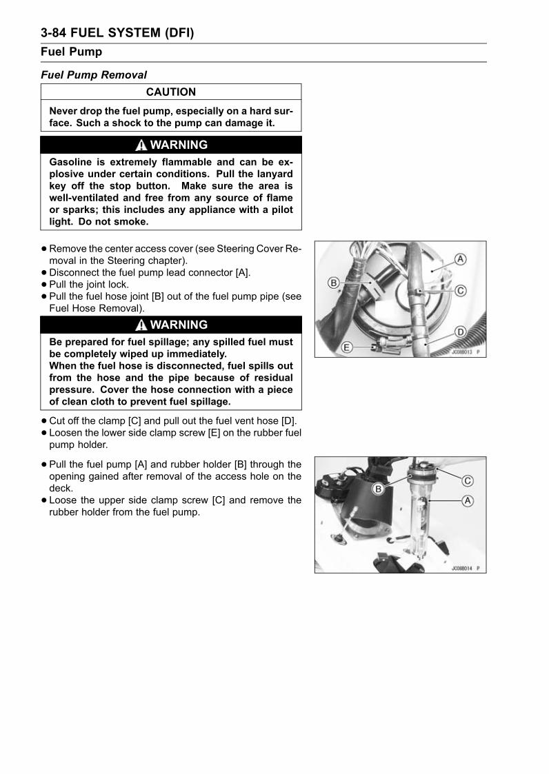
3-84 FUEL SYSTEM (DFI)Fuel Pump
Fuel Pump RemovalCAUTION
Never drop the fuel pump, especially on a hard sur-face. Such a shock to the pump can damage it.
WARNINGGasoline is extremely flammable and can be ex-plosive under certain conditions. Pull the lanyardkey off the stop button. Make sure the area iswell-ventilated and free from any source of flameor sparks; this includes any appliance with a pilotlight. Do not smoke.
•Remove the center access cover (see Steering Cover Re-moval in the Steering chapter).• Disconnect the fuel pump lead connector [A].• Pull the joint lock.• Pull the fuel hose joint [B] out of the fuel pump pipe (seeFuel Hose Removal).
WARNINGBe prepared for fuel spillage; any spilled fuel mustbe completely wiped up immediately.When the fuel hose is disconnected, fuel spills outfrom the hose and the pipe because of residualpressure. Cover the hose connection with a pieceof clean cloth to prevent fuel spillage.
•Cut off the clamp [C] and pull out the fuel vent hose [D].• Loosen the lower side clamp screw [E] on the rubber fuelpump holder.
• Pull the fuel pump [A] and rubber holder [B] through theopening gained after removal of the access hole on thedeck.• Loose the upper side clamp screw [C] and remove therubber holder from the fuel pump.

FUEL SYSTEM (DFI) 3-85Fuel Pump
Fuel Pump Installation•Press down the rubber holder [A] onto the fuel pump [B]so the stepped part [C] of the holder completely contactsthe flanged part [D] of the pump.• Pressing down the rubber holder onto the fuel pump,tighten the small diameter clamp [E].
NOTEInstall the rubber holder onto the fuel pump so the rub-ber holder top surface [F] must be below the top surface[G] of the fuel pump to prevent any water from collect-ing on top of the pump.
• Install the O-ring [A] to the space between fuel pump [B]and rubber holder [C] so it completely contacts the flangedpart [D] of the pump.• Insert the fuel pump with rubber holder and O-ring into thetank so its fuel hose fittings face starboard side (see Ca-ble, Wire, and Hose Routing in Appendix chapter). Andpress down the pump so the O-ring [A] completely con-tacts the top surface of the tank [E].• Tighten the large diameter clamp [F] securely.

3-86 FUEL SYSTEM (DFI)Fuel Pump
• Install the fuel pump [A] in the fuel tank [B].L/H [C]R/H [D]BOW [E]45° [F]
• Install the following to the fuel pump.Fuel Hose (see Fuel Hose Installation)Fuel Tank Vent HoseFuel Pump Lead Connector
Install the return fuel hose so that the large side [A] of thefuel hose fits the joint [B] (JT1500C8F).
NOTEThe main fuel hose is larger than the return fuel hose.
Power Source Voltage InspectionNOTE
Be sure the battery is fully charged.

FUEL SYSTEM (DFI) 3-87Fuel Pump
•Remove the front storage pocket (see Hull/Engine Hoodchapter).• Connect the hand tester (25 V DC) [A] to the fuel pumplead connector [B], using the needle adapter set [C].Special Tools - Hand Tester: 57001-1394
Needle Adapter Set: 57001-1457
•Turn the ignition switch ON and push the lanyard key un-der the stop button.• Pushing the start button, run the engine 5 ∼ 6 seconds atidling to measure the power source voltage.Wait 15 seconds before using the starter again.Pump Power Source VoltageConnectionsTester (+) → W/R lead [D]Tester (–) → Battery (–) Terminal [E]
Power Source Voltage at Pump Lead ConnectorStandard: Battery Voltage
If the reading is good, the power source voltage is normal.Inspect the operating voltage.If there is no battery voltage, check the following:Main Fuse 20 AWiring for Fuel Pump Power Source (see Fuel PumpCircuit in this chapter)
Operating Voltage InspectionNOTE
Be sure the battery is fully charged.
•Remove the front storage pocket (see Hull/Engine Hoodchapter).• Connect the hand tester [A] to the connector [B], usingthe needle adapter set [C].Special Tools - Hand Tester: 57001-1394
Needle Adapter Set: 57001-1457
•Turn the ignition switch ON and push the lanyard key un-der the stop button.• Pushing the start button, run the engine 5 ∼ 6 seconds atidling to measure the operating voltage.Wait 15 seconds before using the starter again.Pump Operating VoltageConnectionsTester (+) → W/R leadTester (–) → BK lead
Operating VoltageStandard: Battery Voltage
If the reading stays on battery voltage but the pumpdoesn’t work, replace the pump.If there is no battery voltage at all, check the ECU forits ground and power supply (see ECU Power Supply In-spection).If the ground and power supply are good, check the fuelpump wiring.

3-88 FUEL SYSTEM (DFI)Fuel Pump
Fuel Pump Relay Removal•Refer to the Relay Assembly Removal in the DFI PowerSource section.
Fuel Pump Relay Inspection•Refer to the Relay Assembly Inspection in the DFI PowerSource section.
1. ECU2. Joint Connector 8 (Vcc)3. Joint Connector 7 (Vcc)4. Joint Connector 4 (Power (12V) - Injector)5. System Relay6. Fuel Pump Relay7. Main (ECU) Relay8. Joint Connector 3 (Switch (12V))9. Fuel Pump
10. Joint Connector 211. Joint Connector 112. Joint Connector 12 (Ground)13. Joint Connector 11 (Ground)14. Battery15. Main Fuse 20A16. Joint Connector 9 (Ground Cntrol)

FUEL SYSTEM (DFI) 3-89Fuel Tank
Fuel Tank Removal•Drain the fuel tank into a suitable container.
WARNINGGasoline is extremely flammable and can be explo-sive under certain conditions. Pull the lanyard keyoff the stop button. Do not smoke. Make sure thearea is well ventilated and free from any source offlame or sparks; this includes any appliance with apilot light.
•Remove the engine (see Engine Removal in the EngineRemoval/Installation chapter).
• Disconnect the following from the main harness.Vehicle-down Sensor Lead Connector [A]Ignition Coil Lead ConnectorsRegulator/rectifier Lead Connector [B]• Remove the bracket [C] out of the engine compartment.
• Remove the fuel filler tube from the fuel tank.• Unhook the fuel tank straps [A].

3-90 FUEL SYSTEM (DFI)Fuel Tank
•Remove the fuel tank [A] out of the hull as shown.Remove the fuel pump [B] (see Fuel Pump Removal)
Fuel Tank Installation•Be sure the float [A] in place before putting the fuel tankinto the hull.• Install the fuel hose (see Fuel Hose Installation).• Route the following correctly (see Cable, Wire, and HoseRouting section in Appendix chapter).Fuel HoseFuel Tank Vent HoseOther Wire and Harness
Fuel Tank Cleaning•Remove the fuel tank (see Fuel Tank Removal).• Drain the tank into a suitable container.
WARNINGGasoline is extremely flammable and can be explo-sive under certain conditions. Pull the lanyard keyoff the stop button. Do not smoke. Make sure thearea is well ventilated and free from any source offlame or spark; this includes any appliance with apilot light.
•Flush the tank repeatedly with high-flash-point solvent un-til it is clean. It may be necessary to put a few marbles orpieces of clean gravel into the tank and shake it, to knockloose any foreign matter in the bottom.
WARNINGClean the tank in a well-ventilated area, and takeample care that there are no sparks or flame any-where near the working area; this includes any ap-pliance with a pilot light. Do not use gasoline or alow-flash point solvent to clean the tank. A fire orexplosion could result.

FUEL SYSTEM (DFI) 3-91Fuel Tank
Fuel Filler and Tube Removal•Remove the front access cover (see Front Access CoverRemoval/Installation in the Hull/Engine Hood chapter).• Loosen the fuel filler tube clamp screws [A] and removethe fuel filler tube [B].
• Remove the left side cover (see Side Cover Removal inthe Hull/Engine Hood chapter).
• Take out the nut [A] in the filler flange and remove the fuelfiller [B].

3-92 FUEL SYSTEM (DFI)Fuel Tank
•Note the following when installing the tube [A].Fit [B] the parting line of tube to mark on the tank.
Install the lower clamp [A] so that its screw head screwpoints straight line [B] or inclined line [C].
Fuel Filler and Tube Installation•Clean the deck and filler on their mating surfaces withgreaseless, high-flash point solvent.
WARNINGClean the parts in a well-ventilated area, and takeample care that there are no sparks or flame any-where near the working area; this includes any ap-pliance with a pilot light. Do not use gasoline or alow-flash point solvent. A fire or explosion couldresult.
•Replace the fuel filler gasket [A] with a new one.• Tighten the fuel filler tube clamp screws.Torque - Fuel Filler Tube Clamp Screws: 2.9 N·m (0.30
kgf·m, 26 in·lb)

ENGINE LUBRICATION SYSTEM 4-1
4
Engine Lubrication SystemTable of Contents
Exploded View........................................................................................................................ 4-2Engine Oil Flow Chart............................................................................................................. 4-4Specifications ......................................................................................................................... 4-7Special Tool and Sealant ........................................................................................................ 4-8Engine Oil and Oil Filter.......................................................................................................... 4-9
Oil Level Inspection........................................................................................................... 4-9Engine Oil Change............................................................................................................ 4-11Oil Filter Replacement ...................................................................................................... 4-11
Oil Cooler................................................................................................................................ 4-12Oil Cooler Removal........................................................................................................... 4-12Oil Cooler Installation........................................................................................................ 4-12Oil Cooler Disassembly..................................................................................................... 4-13Oil Cooler Assembly ......................................................................................................... 4-13Oil Cooler Inspection......................................................................................................... 4-14
Breather Case and Oil Separator Tank................................................................................... 4-15Breather Case Removal.................................................................................................... 4-15Breather Case Installation................................................................................................. 4-15Oil Separator Tank Removal ............................................................................................. 4-15Oil Separator Tank Installation .......................................................................................... 4-16Blowby Gas System Inspection ........................................................................................ 4-16
Oil Pan.................................................................................................................................... 4-17Oil Pan Removal ............................................................................................................... 4-17Oil Pan Installation ............................................................................................................ 4-17
Oil Pump Sprocket, Oil Pump and Oil Pressure Relief Valve ................................................. 4-18Oil Pump Sprocket Removal............................................................................................. 4-18Oil Pump Sprocket Installation.......................................................................................... 4-18Oil Pump Removal ............................................................................................................ 4-19Oil Pump Installation ......................................................................................................... 4-19Oil Pump Inspection.......................................................................................................... 4-20Oil Screen Removal .......................................................................................................... 4-20Oil Screen Installation ....................................................................................................... 4-20Oil Pressure Relief Valve Inspection................................................................................. 4-21Oil Pump Sprocket Chain Removal .................................................................................. 4-21
Oil Pressure Measurement..................................................................................................... 4-22Oil Pressure Measurement ............................................................................................... 4-22
Oil Pressure Switch ................................................................................................................ 4-24Oil Pressure Switch Removal ........................................................................................... 4-24Oil Pressure Switch Installation ........................................................................................ 4-24

4-2 ENGINE LUBRICATION SYSTEMExploded View

ENGINE LUBRICATION SYSTEM 4-3Exploded View
TorqueNo. Fastener
N·m kgf·m ft·lbRemarks
1 Breather Plate Bolts 7.8 0.80 69 in·lb2 Oil Filler Cap – – – Hand-tighten3 Oil Passage Plugs 20 2.0 14 L4 Oil Separator Tank Mounting Screws 4.9 0.50 43 in·lb L5 Breather Case Mounting Bolts 7.8 0.80 69 in·lb6 Breather Pipe Bolts 8.8 0.90 78 in·lb7 Oil Passage Joints 11 1.1 95 in·lb L8 Oil Cooler Assembly Bolts 7.8 0.80 69 in·lb9 Oil Pressure Switch 15 1.5 11 SS10 Oil Passage Bolt 78 8.0 58 S11 Oil Filter 18 1.8 13 EO12 Oil Cooler Positioning Bolt 20 2.0 14 S13 Oil Pan Bolts 7.8 0.80 69 in·lb S14 Dipstick Tube Bolts 7.8 0.80 69 in·lb L, S15 Oil Pump Sprocket Bolt 16 1.6 12 LN16 Oil Pump Cover Bolts 7.8 0.80 69 in·lb17 Oil Pressure Relief Valve 15 1.5 11 LN18 Oil Pipe Bolts 7.8 0.80 69 in·lb19 Oil Pump Chain Guide Bolt 7.8 0.80 69 in·lb20 Chain Guide Spring Plate Bolt 7.8 0.80 69 in·lb21 Oil Pump Body Plug 20 2.0 14 L22 Oil Pump Body Bolts 7.8 0.80 69 in·lb23 Oil Screen Bolts 7.8 0.80 69 in·lb24 Water Hose Joints 20 2.0 14 SSEO: Apply engine oil.G: Apply grease.L: Apply a non-permanent locking agent.LN: Apply a non-permanent locking agent (High Strength: Loctite 271 equivalent).MO: Apply molybdenum disulfide oil solution (mixture of the engine oil and molybdenum disulfide
grease in a weight ratio 10 : 1).S: Follow the specific tightening sequence.SS: Apply silicone sealant (see text).

4-4 ENGINE LUBRICATION SYSTEMEngine Oil Flow Chart

ENGINE LUBRICATION SYSTEM 4-5Engine Oil Flow Chart

4-6 ENGINE LUBRICATION SYSTEMEngine Oil Flow Chart

ENGINE LUBRICATION SYSTEM 4-7Specifications
Item StandardEngine OilGrade API SE, SF, or SG
API SH, SJ or SL with JASO MAViscosity SAE 10W-40Capacity 4.0 L (4.2 US qt, with or without the filter)
5.0 L (5.3 US qt, when engine is completely dry)Level Between upper and lower level lines (see text)
Oil Pressure MeasurementOil pressure @3 000 r/min (rpm),oil temperature 74°C (165°F)
461 kPa (4.7 kgf/cm², 67 psi)
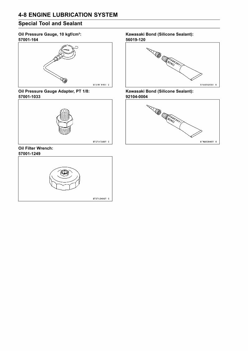
4-8 ENGINE LUBRICATION SYSTEMSpecial Tool and Sealant
Oil Pressure Gauge, 10 kgf/cm²:57001-164
Oil Pressure Gauge Adapter, PT 1/8:57001-1033
Oil Filter Wrench:57001-1249
Kawasaki Bond (Silicone Sealant):56019-120
Kawasaki Bond (Silicone Sealant):92104-0004

ENGINE LUBRICATION SYSTEM 4-9Engine Oil and Oil Filter
WARNINGWatercraft operation with insufficient, deteriorated,or contaminated engine oil will cause acceleratedwear and may result in engine seizure, accident,and injury.
Oil Level InspectionThis watercraft engine is equipped with a semi-dry sump.
In the semi-dry sump engine, the oil level difference is verylarge between the level measured after just stopping andthat after leaving for a long time.It is necessary to check the specified amount of oil is in
the engine before starting the engine every day. At thistime use the cold mark of the level gauge. Then run theengine to lubricate the engine parts sufficiently. After thatit is necessary to check the level by using hot mark of thelevel gauge.
Preliminary Check•Remove the seat (see Hull/Engine Hood chapter).•Whenever checking the engine oil level, keep the water-craft level side to side and fore to aft as much as possible.Level Ground [A]Side Bumper [B]Parallel [C]
• Remove the dipstick [A], wipe it dry and insert it back tothe dipstick tube [B], and then remove it again to checkthe oil level.
• The oil level must be between the High [A] and Low [B]level lines on the dipstick [C] (Use level lines when engineis cold).High Level Line when Cold [A]Low Level Line when Cold [B]Dipstick [C]High Level Line when Hot [D]Low Level Line when Hot [E]

4-10 ENGINE LUBRICATION SYSTEMEngine Oil and Oil Filter
CAUTIONRacing the engine before the oil reaches every partcan cause engine seizure.If the engine oil gets extremely low or if the oil pumpor oil passages clog up or otherwise do not functionproperly, the oil pressure warning light will light. Ifthis light stays onwhen the engine is running aboveidle speed, stop the engine immediately and find thecause.
If the oil level is too high, remove the excess oil using asyring or some other suitable device.If the oil level is too low, add the oil to the low level linethrough the oil filter opening (see Periodic Maintenancechapter). Use the same type and make of oil that is al-ready in the engine.
NOTEIf the engine oil type and make are unknown, use anybrand of the specified oil to top off the level in preferenceto running the engine with the oil level low. Then at yourearliest convenience, change the oil completely.
Ordinary (standard) Check•The preliminary is checked before the ordinary check.• Install the removed parts.• Launch the watercraft.• Start the engine for several minutes.• Ride the watercraft and run the engine at about 5 000 rpmfor 5 minutes.• Stop the engine and let it cool down for 10 minutes.• Steady the watercraft in calm water to prevent movement,or on the ground, keep the watercraft level side to sideand fore to aft as much as possible.
NOTESince the trim and list of the watercraft will significantlyaffect the oil level, be sure that the operator and/orcargo are not aboard the watercraft when measuringthe oil level.Also make the fuel tank [A] full if it is not full as shownto keep the watercraft level.Fuel Tank Filler Neck [B]Fuel Full Level [C]Fuel [D]This measuring procedure with the watercraft afloatshould be followed when the oil level is found low andto be added.

ENGINE LUBRICATION SYSTEM 4-11Engine Oil and Oil Filter
•Remove the seat (see Hull/Engine Hood chapter)• Remove the dipstick [A], wipe it dry and insert it back tothe dipstick tube [B], and then remove it again to checkthe oil level.
• Check the oil level using the hot level mark on the dipstick[A].High Level Line when Hot [B]Low Level Line when Hot [C]
If the oil level is too high, drain the excess oil thoroughlyfrom the dipstick tube [A] using a commercially-availablevacuum pump [B].
If the oil level is too low, add the oil to the high level linethrough the oil filler opening (see Periodic Maintenancechapter). Use the same type and make of oil that is al-ready in the engine.
NOTEIf the engine oil type and make are unknown, use anybrand of the specified oil to top off the level in preferenceto running the engine with the oil level low. Then at yourearliest convenience, change the oil completely.
Engine Oil Change•Refer to Engine Oil Change in the Periodic Maintenancechapter.
Oil Filter Replacement•Refer to Oil Filter Replacement in the Periodic Mainte-nance chapter.

4-12 ENGINE LUBRICATION SYSTEMOil Cooler
Oil Cooler Removal•Remove:Seat (see Hull/Engine Hood chapter)Air Filter with Inlet Duct (see Fuel System (DFI) chapter)Inlet Manifold (see Fuel System (DFI) chapter)• Disconnect the oil pressure switch connector [A].• Loosen the clamp screws [B] and remove the oil coolercooling hoses [C] from the oil cooler.
• Remove the oil filter [A] with the oil filter wrench [B].Place a rag or cloth [C] under the oil filter to receive theremaining oil.Special Tool - Oil Filter Wrench: 57001-1249
•Unscrew the oil cooler positioning bolt [A].• Unscrew the oil passage bolt [B] and remove the oil cooler[C].• Place a rag or cloth [D] under the oil cooler to receive theremaining oil.
Oil Cooler Installation•Replace the O-ring [A] with new one and apply grease tonew O-ring.• Fit the O-ring on the oil cooler [B] securely.
• Install the oil cooler positioning bolt [A] and the oil pas-sage bolt [B] temporarily.Tighten the passage bolt first.Next, tighten the positioning bolt.Torque - Oil Passage Bolt: 78 N·m (8.0 kgf·m, 58 ft·lb)
Oil Cooler Positioning Bolt: 20 N·m (2.0 kgf·m, 14ft·lb)

ENGINE LUBRICATION SYSTEM 4-13Oil Cooler
•Apply engine oil to the thread [A] of the passage bolt andO-ring [B] of the oil filter [C].• Tighten the oil filter (P/No. 16097-1072).Torque - Oil Filter: 18 N·m (1.8 kgf·m, 13 ft·lb)
•Connect the oil pressure switch connector securely.• Install the cooling hoses (see Cable, Wire and Hose Rout-ing in Appendix chapter).• Install the inlet manifold (see Fuel System (DFI) chapter).Oil Cooler Disassembly•Remove:Oil Cooler (see Oil Cooler Removal)Water Hose Joints [A]Oil Pressure Switch [B]Oil Cooler Assembly Bolts [C]
• Remove the O-ring [A].• Turn the oil cooler up side down, and remove the assem-bly bolts [B].
• Separate the oil cooler.Inside Oil Cooler Cover [A]O-rings [B]Oil Cooler [C]Outside Oil Cooler Cover [D]
Oil Cooler Assembly•Apply grease to new O-rings, and fit them on to eachgroove of the coolers securely.• Apply silicon sealant to the joints and tighten them.Sealant - Kawasaki Bond (Silicone Sealant): 56019-120
Torque - Oil Cooler Assembly Bolts: 7.8 N·m (0.80 kgf·m,69 in·lb)
Water Hose Joints: 20 N·m (2.0 kgf·m, 14 ft·lb)
• Install the oil cooler (see Oil Cooler Installation).
4-14 ENGINE LUBRICATION SYSTEMOil Cooler
Oil Cooler Inspection•Start the engine to check for water and oil leaks.If the water and oil leak, replace the O-rings.
WARNINGDo not run the engine in a closed area. Exhaustgases contain carbon monoxide, a colorless, odor-less, poisonous gas which can be lethal.
CAUTIONDo not run the engine without cooling water supplyfor more than 15 seconds, especially in high revolu-tionary speed or severe engine and exhaust systemdamage will occur.
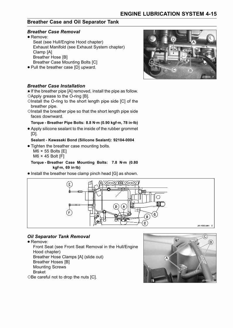
ENGINE LUBRICATION SYSTEM 4-15Breather Case and Oil Separator Tank
Breather Case Removal•Remove:Seat (see Hull/Engine Hood chapter)Exhaust Manifold (see Exhaust System chapter)Clamp [A]Breather Hose [B]Breather Case Mounting Bolts [C]• Pull the breather case [D] upward.
Breather Case InstallationIf the breather pipe [A] removed, install the pipe as follow.Apply grease to the O-ring [B].Install the O-ring to the short length pipe side [C] of thebreather pipe.Install the breather pipe so that the short length pipe sidefaces downward.Torque - Breather Pipe Bolts: 8.8 N·m (0.90 kgf·m, 78 in·lb)
•Apply silicone sealant to the inside of the rubber grommet[D].Sealant - Kawasaki Bond (Silicone Sealant): 92104-0004
•Tighten the breather case mounting bolts.M6 × 55 Bolts [E]M6 × 45 Bolt [F]Torque - Breather Case Mounting Bolts: 7.8 N·m (0.80
kgf·m, 69 in·lb)
• Install the breather hose clamp pinch head [G] as shown.
Oil Separator Tank Removal•Remove:Front Seat (see Front Seat Removal in the Hull/EngineHood chapter)Breather Hose Clamps [A] (slide out)Breather Hoses [B]Mounting ScrewsBraket
Be careful not to drop the nuts [C].

4-16 ENGINE LUBRICATION SYSTEMBreather Case and Oil Separator Tank
•Remove:Breather Hose Clamp [A]Breather Hose [B]Oil Separator Tank [C]
NOTEHold the hose end to the upward. The oil will flow out ifthe hose lies at the bottom.
Oil Separator Tank Installation•When installing the breather hoses, avoid sharp bending,kicking, flattening or twisting, and route the hoses accord-ing to Hose Routing section in Appendix chapter.• Apply a non-permanent locking agent to the oil separatortank mounting screws.• Tighten:Be careful not to drop the nuts.Torque - Oil Separator Tank Mounting Screws: 4.9 N·m
(0.50 kgf·m, 43 in·lb)
Blowby Gas System Inspection•Be certain that all the hoses are routed without being flat-tened or kinked, and are connected correctly.If they are not, correct them.• Inspect the breather hoses [A], breather pipes and theair filter drain caps for damage or signs of deterioration.Squeeze the hoses. These hoses should not be hard andbrittle, nor should be soft or swollen.Replace any damaged hoses.• Check that the hoses and aps are securely connected.The air filter drain caps [A] is provided beneath the air filterare housing catches the water or oil from the bottom ofthe air filter housing. Usually water or oil does not collectat the bottom of the housing. In the event that water isdrawn in through the duct, or if engine oil is blown back,drain the housing.• Pull the air filter drain plugs to drain the water or breatheroil when changing engine oil.

ENGINE LUBRICATION SYSTEM 4-17Oil Pan
Oil Pan Removal•Remove:Engine Oil (drain, see Periodic Maintenance chapter)Engine (see Engine Removal/Installation chapter)• Turn the engine to the side.• Unscrew the dipstick tube bolts [A] and pull out the dip-stick tube [B].
• Unscrew the oil pan bolts [A] and remove the oil pan [B].
Oil Pan Installation•Tighten the oil pan bolts following the tightening sequence[1 ∼ 17].Torque - Oil Pan Bolts: 7.8 N·m (0.80 kgf·m, 69 in·lb)
•Apply grease to the O-ring [A] on the dipstick tube [B].• Apply a non-permanent locking agent to the dipstick tubebolts.• Tighten all the dipstick tube bolts temporary.First, tighten the oil pan side bolt. Next, tighten the cylin-der head side bolts.Torque - Dipstick Tube Bolts: 7.8 N·m (0.80 kgf·m, 69 in·lb)

4-18 ENGINE LUBRICATION SYSTEMOil Pump Sprocket, Oil Pump and Oil Pressure Relief Valve
Oil Pump Sprocket Removal•Drain:Engine Oil (see Periodic Maintenance chapter)• Remove:Engine (see Engine Removal/Installation chapter)Oil Pan (see Oil Pan Removal)Crankshaft Sensor Cover Bolts [A]Crankshaft Sensor Cover [B]
• Unscrew the oil pump chain guide bolt [A],
• Unscrew the spring plate bolt [A] and remove the springplate [B], spring [C] and the oil pump chain guide [D].• Unscrew the oil pump sprocket bolt [E].• Pull out the oil pump sprocket [F] together with the oilpump sprocket chain [G].
Oil Pump Sprocket Installation•Engage the oil pump chain [A] to the oil pump sprocket[B].• Install the sprocket with the chain to the oil pump shaft[C].• Apply a non-permanent locking agent (High Strength:Loctite 271 equivalent) to the sprocket bolt.• Tighten:Torque - Oil Pump Sprocket Bolt: 15 N·m (1.5 kgf·m, 11
ft·lb)
• Install the oil pump chain guide [A] and collar [B] asshown.
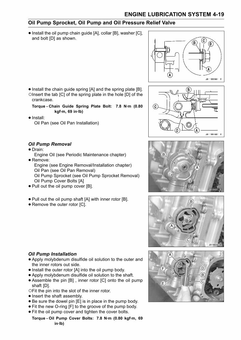
ENGINE LUBRICATION SYSTEM 4-19Oil Pump Sprocket, Oil Pump and Oil Pressure Relief Valve
• Install the oil pump chain guide [A], collar [B], washer [C],and bolt [D] as shown.
• Install the chain guide spring [A] and the spring plate [B].Insert the tab [C] of the spring plate in the hole [D] of thecrankcase.Torque - Chain Guide Spring Plate Bolt: 7.8 N·m (0.80
kgf·m, 69 in·lb)
• Install:Oil Pan (see Oil Pan Installation)
Oil Pump Removal•Drain:Engine Oil (see Periodic Maintenance chapter)• Remove:Engine (see Engine Removal/Installation chapter)Oil Pan (see Oil Pan Removal)Oil Pump Sprocket (see Oil Pump Sprocket Removal)Oil Pump Cover Bolts [A]• Pull out the oil pump cover [B].
• Pull out the oil pump shaft [A] with inner rotor [B].• Remove the outer rotor [C].
Oil Pump Installation•Apply molybdenum disulfide oil solution to the outer andthe inner rotors out side.• Install the outer rotor [A] into the oil pump body.• Apply molybdenum disulfide oil solution to the shaft.• Assemble the pin [B] , inner rotor [C] onto the oil pumpshaft [D].Fit the pin into the slot of the inner rotor.• Insert the shaft assembly.• Be sure the dowel pin [E] is in place in the pump body.• Fit the new O-ring [F] to the groove of the pump body.• Fit the oil pump cover and tighten the cover bolts.Torque - Oil Pump Cover Bolts: 7.8 N·m (0.80 kgf·m, 69
in·lb)

4-20 ENGINE LUBRICATION SYSTEMOil Pump Sprocket, Oil Pump and Oil Pressure Relief Valve
• Install:Oil Pump Sprocket (see Oil Pump Sprocket Installation)Oil Pan (see Oil Pan Installation)
Oil Pump Inspection•Remove the oil pump parts.• Visually inspect the oil pump outer, inner rotors and cover.If there is any damage or uneven wear, replace the rotorsand cover.
Oil Screen Removal•Remove:Engine (see Engine Removal/Installation chapter)Oil Pan (see Oil Pan Removal)Oil Screen Bolts [A]• Pull out the soil screen [B] to the coupling side.
Oil Screen Installation•Clean the oil screen [A] with high-flash point solvent andremove any particles stuck to it.
WARNINGClean the screen in a well-ventilated area, and takecare that there is no spark or flame anywhere nearthe working area. Because of the danger of highlyflammable liquids, do not use gasoline or low-flashpoint solvents.
NOTEWhile cleaning the screen, check for any metal particlesthat might indicate internal engine damage.
•Apply grease to the O-ring [A].• Install the oil screen [B].• Tighten:Torque - Oil Screen Bolts [C]: 7.8 N·m (0.80 kgf·m, 69 in·lb)
• Install:Oil Pan (see Oil Pan Installation)

ENGINE LUBRICATION SYSTEM 4-21Oil Pump Sprocket, Oil Pump and Oil Pressure Relief Valve
Oil Pressure Relief Valve Inspection•Remove:Oil Pan (see Oil Pan Removal)Relief Valve [A]
• Check to see if the valve [A] slides smoothly when push-ing it in with a wooden or other soft rod, and see if it comesback to its seat by spring [B] force.
NOTEInspect the valve in its assembled state. Disassemblyand assembly may change the valve performance.
If any rough spots are found during above inspection,wash the valve clean with a high-flash point solvent andblow out any foreign particles that may be in the valve withcompressed air.
WARNINGClean the relief valve in a well-ventilated area, andtake care that there is no spark or flame anywherenear the working area. Because of the danger ofhighly flammable liquids, do not use gasoline or low-flash point solvent.
If cleaning does not solve the problem, replace the reliefvalve as an assembly. The relief valve is precisely madewith no allowance for replacement of individual parts.• Apply a non-permanent locking agent to the relief valve.• Install the relief valve.Torque - Oil Pressure Relief Valve: 15 N·m (1.5 kgf·m, 11 ft
·lb)
Oil Pump Sprocket Chain Removal•Split the crankcase (see Engine Bottom End chapter).• Remove the camshaft chain [A] and the oil pump sprocketchain [B].

4-22 ENGINE LUBRICATION SYSTEMOil Pressure Measurement
Oil Pressure Measurement•Remove:Seat (see Hull/Engine Hood chapter)Inlet Manifold (see Fuel System (DFI) chapter)Oil Pressure Switch Connector [A] (disconnect)Oil Pressure Switch [B]
• Install the oil pressure gauge adapter [A] to the switchhole.Special Tool - Oil Pressure Gauge Adapter, PT 1/8: 57001
-1033
• Install the oil pressure gauge [A] to the adapter.Special Tool - Oil Pressure Gauge, 10 kgf/cm²: 57001-164
•Out off a rag or cloth.• Install:Inlet Manifold (see Fuel System (DFI) chapter)
• Launch the watercraft.• Start the engine for several minutes.• Run the engine at the specified speed, and read the oilpressure gauge.If the oil pressure is significantly below the specification,inspect the oil pump and relief valve.If the oil pump and relief valve are not at fault, inspect therest of the lubrication system.
Oil PressureStandard: 461 kPa (4.7 kgf/cm², 67 psi) @3 000 r/min
(rpm), oil temperature 74°C (165°F)
•Stop the engine.• Raise the watercraft to the land.• Remove:Inlet ManifoldOil Pressure Gauge and Adapter

ENGINE LUBRICATION SYSTEM 4-23Oil Pressure Measurement
WARNINGTake care against burns from hot engine oil thatwill drain through the oil passage when the gaugeadapter is removed.
• Install:Oil Pressure Switch (see Oil Pressure Switch Installa-tion)Inlet Manifold

4-24 ENGINE LUBRICATION SYSTEMOil Pressure Switch
Oil Pressure Switch Removal•Remove:Seat (see Hull/Engine Hood chapter)Inlet Manifold (see Fuel System (DFI) chapter)• Disconnect:Switch Connector [A]
• Place a rag or cloth under the oil pressure switch [A] andremove the oil pressure switch.Do not damage the connect part [B] of the switch.
Oil Pressure Switch Installation•Apply silicone sealant to the threads of the oil pressureswitch and tighten it.Sealant - Kawasaki Bond (Silicone Sealant): 56019-120
Torque - Oil Pressure Switch: 15 N·m (1.5 kgf·m, 11 ft·lb)
•Connect the switch connector.• Install the removed parts.

EXHAUST SYSTEM 5-1
5
Exhaust SystemTable of Contents
Exploded View........................................................................................................................ 5-2Exhaust Manifold .................................................................................................................... 5-4
Exhaust Manifold Removal ............................................................................................... 5-4Exhaust Manifold Installation ............................................................................................ 5-5Exhaust Manifold Cleaning and Inspection....................................................................... 5-6
Exhaust Pipe .......................................................................................................................... 5-7Exhaust Pipe Removal...................................................................................................... 5-7Exhaust Pipe Installation................................................................................................... 5-7Exhaust Pipe Cleaning and Inspection ............................................................................. 5-8
Water Box Muffler ................................................................................................................... 5-9Water Box Muffler Removal .............................................................................................. 5-9Water Box Muffler Installation ........................................................................................... 5-9Water Box Muffler Inspection ............................................................................................ 5-10

5-2 EXHAUST SYSTEMExploded View

EXHAUST SYSTEM 5-3Exploded View
TorqueNo. Fastener
N·m kgf·m ft·lbRemarks
1 Exhaust Manifold Mounting Nuts 25 2.5 18 S2 Exhaust Manifold Mounting Bolts 25 2.5 18 L, S3 Bypass Nozzle – – – LN4 Flushing Hose Joint 11 1.1 95 in·lb L5 Water Hose Joint 11 1.1 95 in·lb L6 Water Temperature Sensor 15 1.5 11 see chapter 37 Exhaust Pipe Mounting Plate Bolts 29 3.0 22 L8 Exhaust Pipe Mounting Bolts 29 3.0 22EO: Fill the hollow with the engine oil (10W-30).G: Apply grease.L: Apply a non-permanent locking agent.LN: Apply a non-permanent locking agent (High Strength: Loctite 271 equivalent).S: Follow the specific tightening sequence.SY: Apply synthetic rubber adhesive.

5-4 EXHAUST SYSTEMExhaust Manifold
Exhaust Manifold Removal•Remove:Seat (Seat Removal in the Hull/Engine Hood chapter)Rear Grip Plate (Rear Grip Plate Removal in the Hull/En-gine Hood chapter)Oil Separator Tank [A] with the Oil Separator Hoses (seeOil Separator Tank Removal in the Engine LubricationSystem chapter)Air Filter [B] (see Air Filter Removal in the Fuel System(DFI) chapter)• Disconnect:Spark Plug Caps [C]Water Temperature Sensor Connector
• Disconnect:Hoses [A]
• Remove:Bolts [A] and CollarsExhaust Pipe Mounting Plate [B]• Loosen:Joint Tube Clamp Screws [C]
• Remove the exhaust manifold mounting nuts [A] and bolts[B].• Remove the exhaust manifold from the engine.

EXHAUST SYSTEM 5-5Exhaust Manifold
•Disconnect the exhaust pipe [A] from the left water boxmuffler [B] by pulling the exhaust manifold with the ex-haust pipe toward the front [C].
• Take out the exhaust manifold with the exhaust pipe fromthe hull.• Disconnect the hose [A] from the exhaust pipe.
Exhaust Manifold InstallationNOTE
Unhook the rubber strap and remove the front exhausttube from the water box muffler for easier installationof the exhaust manifold, and after connecting the waterbox muffler to the exhaust pipe, hook the rubber strapand install the tube.
•Replace the exhaust manifold gasket [A] with a new one.• Install the exhaust manifold and the washers [B] and col-lars [C] as shown.• Apply a non-permanent locking agent to the exhaust man-ifold mounting bolts.
• Tighten the exhaust manifold mounting nuts and bolts fol-lowing the specified tightening sequence.Torque - Exhaust Manifold Mounting Nuts: 25 N·m (2.5
kgf·m, 18 ft·lb)Exhaust Manifold Mounting Bolts: 25 N·m (2.5kgf·m, 18 ft·lb)
•Apply a non-permanent locking agent to the exhaust pipemounting plate bolts and install the collars.• Tighten:Torque - Exhaust Pipe Mounting Plate Bolts: 30 N·m (3.0
kgf·m, 22 ft·lb)
•Connect the water box muffler to the exhaust pipe afterbinding the two rings with the paper tape (see ExhaustPipe Installation).

5-6 EXHAUST SYSTEMExhaust Manifold
If the water temperature sensor is removed, see watertemperature sensor removal/installation in Fuel Systemchapter.• Check the hose routing and clamp screw position (seeCable, Wire and Hose Routing in Appendix chapter).
Exhaust Manifold Cleaning and Inspection•Remove the exhaust manifold parts.• Clean the carbon deposits out of the exhaust passageswith a blunt, roundedged tool.• Flush foreign matter out of the water passages with freshwater.• Check the insides of the water passages for corrosion.Check the gasket surfaces for nicks or other damage.If there is excessive corrosion or if the gasket surfaces areso badly damaged that they will not seal properly, replacethe part.

EXHAUST SYSTEM 5-7Exhaust Pipe
Exhaust Pipe Removal•Remove:Exhaust Manifold with Exhaust Pipe (see Exhaust Man-ifold Removal)Exhaust Pipe Mounting Bolts [A]Exhaust Pipe [B]
• Remove the joint tube [A] and the two rings.
Exhaust Pipe Installation• Install the two rings [A] in the ring grooves of the exhaustpipe.If the two rings are damaged or warped, replace the rings.
• Bind the two rings [A] securely by putting the paper tape[B] around the rings so that it is easy to insert the waterbox muffler into the exhaust pipe. The paper tape can beburned out soon after firing.• Install the joint tube to the exhaust pipe.
• Replace the exhaust pipe gasket [A] with a new one asshown.• Install the exhaust pipe [B] to the exhaust manifold [C]and tighten the bolts [D].Torque - Exhaust Pipe Mounting Bolts: 30 N·m (3.0 kgf·m,
22 ft·lb)[E] Water Pipe Joint[F] 30°

5-8 EXHAUST SYSTEMExhaust Pipe
Exhaust Pipe Cleaning and Inspection•Remove the exhaust pipe parts.• Clean the carbon deposits out of the exhaust passageswith a blunt, roundedged tool.• Flush foreign matter out of the water passages with freshwater.• Check the insides of the water passage for corrosion.• Check the gasket surface for nicks or other damage.If there is excessive corrosion or if the gasket surfaces areso badly damaged that they will not seal properly, replacethe part.

EXHAUST SYSTEM 5-9Water Box Muffler
Water Box Muffler Removal•Remove:Rear Storage PocketOil Separator Tank with Oil Separator Hoses (see theLubrication System chapter)Air Filter (see the Fuel System chapter)
• Loosen:Joint Tube Clamp Screw (see Exhaust Manifold Re-moval)
• Pull the bilge hoses off the breathers.• Remove the exhaust tubes [A] by loosing the clampscrews [B].• Unhook the rubber straps [C] from the water box muffler.
• Remove:Hoses [A]Exhaust Manifold [B] (see Exhaust Manifold Removal)• Remove the water box mufflers.
Water Box Muffler Installation•Be sure the dampers [A] on the left side water box muffler[B] are in place.
•Make sure the two rings [A] are installed to the correctposition.If the rings are damaged or warped, replace the rings withnew ones.

5-10 EXHAUST SYSTEMWater Box Muffler
•Bind the two rings [A] by putting the paper tape [B] aroundthe rings. The paper tape can be burned out soon afterfiring.
• Install the joint tube to the exhaust pipe.• Install the left water box muffler to the exhaust pipe.• Tighten the clamp securing the front exhaust tube, notingits screw position, and check the hose routing and clampscrew position (see Cable, Wire and Hose Routing in Ap-pendix chapter).
Water Box Muffler Inspection•Remove the left water box muffler.• Empty water out of the water box.• Check the inlet spigot for damage caused by excessiveheat.If there is heat damage to the inlet spigot, check the cool-ing system for blockage (see Cooling System Cleaningand Inspection) and the fuel system for proper adjustment(see Fuel System chapter).

ENGINE TOP END 6-1
6
Engine Top EndTable of Contents
Exploded View........................................................................................................................ 6-2Specifications ......................................................................................................................... 6-6Special Tools and Sealant ...................................................................................................... 6-8Clean Air System.................................................................................................................... 6-11
Air Suction Valve Removal................................................................................................ 6-11Air Suction Valve Installation............................................................................................. 6-11Air Suction Valve Check.................................................................................................... 6-11Clean Air System Hose Inspection ................................................................................... 6-11
Cylinder Head Cover .............................................................................................................. 6-12Cylinder Head Cover Removal ......................................................................................... 6-12Cylinder Head Cover Installation ...................................................................................... 6-12
Camshaft Chain Tensioner ..................................................................................................... 6-13Camshaft Chain Tensioner Removal ................................................................................ 6-13Camshaft Chain Tensioner Installation ............................................................................. 6-13
Camshaft, Camshaft Chain .................................................................................................... 6-15Camshaft Removal ........................................................................................................... 6-15Camshaft Installation ........................................................................................................ 6-16Piston TDC Finding........................................................................................................... 6-17Camshaft, Camshaft Cap Wear ........................................................................................ 6-19Camshaft Runout .............................................................................................................. 6-19Cam Wear......................................................................................................................... 6-19Camshaft Chain Removal ................................................................................................. 6-20
Cylinder Head......................................................................................................................... 6-21Cylinder Compression Measurement................................................................................ 6-21Cylinder Head Removal .................................................................................................... 6-22Cylinder Head Installation ................................................................................................. 6-23Cylinder Head Warp.......................................................................................................... 6-24
Valves ..................................................................................................................................... 6-25Valve Clearance Check..................................................................................................... 6-25Valve Removal .................................................................................................................. 6-25Valve Installation ............................................................................................................... 6-25Valve Guide Removal ....................................................................................................... 6-25Valve Guide Installation .................................................................................................... 6-26Valve-to-Guide Clearance Measurement (Wobble Method) ............................................. 6-26Valve Seat Inspection ....................................................................................................... 6-27Valve Seat Repair ............................................................................................................. 6-27
Cylinder, Pistons..................................................................................................................... 6-32Cylinder Removal.............................................................................................................. 6-32Piston Removal................................................................................................................. 6-32Piston/Cylinder Installation................................................................................................ 6-33Cylinder Wear ................................................................................................................... 6-35Piston Wear ...................................................................................................................... 6-35Piston Ring, Piston Ring Groove Wear............................................................................. 6-35Piston Ring Groove Width................................................................................................. 6-35Piston Ring Thickness ...................................................................................................... 6-36Piston Ring End Gap ........................................................................................................ 6-36

6-2 ENGINE TOP ENDExploded View

ENGINE TOP END 6-3Exploded View
TorqueNo. Fastener
N·m kgf·m ft·lbRemarks
1 Air Suction Valve Cover Bolts 9.8 1.0 87 in·lb2 Cylinder Head Cover Bolts 9.8 1.0 87 in·lb3 Upper Camshaft Chain Guide Bolts 12 1.2 104 in·lb S4 Camshaft Cap Bolts 12 1.2 104 in·lb S5 Cylinder Head Bolts ( 7) 20 2.0 14 S6 Cylinder Head Bolts ( 11) 23 2.3 17 First, MO, S6 Cylinder Head Bolts ( 11) 59 6.0 43 Final, MO, S7 Water Jacket Plugs 20 2.0 14 L8 Cylinder Head Bolts ( 6) 12 1.2 104 in·lb S9 Engine Hook Bolts 20 2.0 1410 Camshaft Position Sensor Bolt 9.8 1.0 87 in·lb LEO: Apply engine oil.G: Apply grease.L: Apply a non-permanent locking agent.
MO: Apply molybdenum disulfide oil solution (mixture of the engine oil and molybdenum disulfidegrease in a weight ratio 10 : 1).
S: Follow the specific tightening sequence.SS: Apply silicone sealant.

6-4 ENGINE TOP ENDExploded View

ENGINE TOP END 6-5Exploded View
TorqueNo. Fastener
N·m kgf·m ft·lbRemarks
1 Exhaust Side Camshaft Chain Guide Bolts (Upper) 25 2.5 182 Exhaust Side Camshaft Chain Guide Bolts (Lower) 12 1.2 104 in·lb3 Upper Camshaft Chain Guide Bolts 12 1.2 104 in·lb S4 Inlet Side Camshaft Chain Guide Bolt 12 1.2 104 in·lb L5 Camshaft Chain Tensioner Mounting Bolts 9.8 1.0 87 in·lb L6 Camshaft Chain Tensioner Cap Bolt 20 2.0 147 Camshaft Position Sensor Rotor Bolt 12 1.2 104 in·lb L8 Water Hose Joint 11 1.1 95 in·lb L9 Oil Passage Joint 11 1.1 95 in·lb L10. Closed coil end faces downward.11. A marking hollow faces exhaust side.EO: Apply engine oil.G: Apply grease.L: Apply a non-permanent locking agent.M: Apply molybdenum disulfide grease.
MO: Apply molybdenum disulfide oil solution (mixture of the engine oil and molybdenum disulfidegrease in a weight ratio 10 : 1).
R: Replacement PartsS: Follow the specific tightening sequence.

6-6 ENGINE TOP ENDSpecifications
Item Standard Service LimitCamshaftsCam Height:Exhaust 36.143 ∼ 36.257 mm (1.4229 ∼ 1.4274 in.) 36.04 mm (1.4189 in.)Inlet 36.440 ∼ 36.554 mm (1.4346 ∼ 1.4391 in.) 36.34 mm (1.431 in.)
Camshaft Journal, CamshaftCap Clearance
0.028 ∼ 0.071 mm (0.0011 ∼ 0.0028 in.) 0.16 mm (0.006 in.)
Camshaft Journal Diameter 23.950 ∼ 23.972 mm (0.9429 ∼ 0.9438 in.) 23.92 mm (0.942 in.)Camshaft Bearing InsideDiameter
24.000 ∼ 24.021 mm (0.9449 ∼ 0.9457 in.) 24.08 mm (0.948 in.)
Camshaft Runout TIR 0.02 mm (0.0008 in.) or less TIR 0.1 mm (0.004 in.)Cylinder HeadCylinder Compression (usable range)
1 185∼ 1 795 kPa (12.1 ∼ 18.3 kgf/cm²,172 ∼ 260 psi) @430 r/min. (rpm)
– – –
Cylinder Head Warp – – – 0.05 mm (0.002 in.)ValvesValve Clearance:Exhaust 0.22 ∼ 0.31 mm (0.0087 ∼ 0.0122 in.) – – –Inlet 0.15 ∼ 0.24 mm (0.0059 ∼ 0.0094 in.) – – –
Valve Head Thickness:Exhaust 0.8 mm (0.03 in.) 0.5 mm (0.02 in.)Inlet 0.5 mm (0.02 in.) 0.25 mm (0.0098 in.)
Valve Stem Bend TIR 0.01 mm (0.0004 in.) or less TIR 0.05 mm (0.002 in.)Valve Stem Diameter:Exhaust 4.955 ∼ 4.970 mm (0.1951 ∼ 0.1957 in.) 4.94 mm (0.194 in.)Inlet 4.975 ∼ 4.990 mm (0.1959 ∼ 0.1965 in.) 4.96 mm (0.195 in.)
Valve Guide Inside Diameter:Exhaust 5.000 ∼ 5.012 mm (0.1969 ∼ 0.1973 in.) 5.07 mm (0.200 in.)Inlet 5.000 ∼ 5.012 mm (0.1969 ∼ 0.1973 in.) 5.07 mm (0.200 in.)
Valve/valve Guide Clearance(Wobble Method):Exhaust 0.09 ∼ 0.17 mm (0.0035 ∼ 0.0067 in.) 0.35 mm (0.014 in.)Inlet 0.03 ∼ 0.11 mm (0.0012 ∼ 0.0043 in.) 0.29 mm (0.011 in.)
Valve Seat Cutting Angle 45°, 32°, 60°, 55° – – –Valve Seating Surface:Outside Diameter:Exhaust 27.6 ∼ 27.8 mm (1.087 ∼ 1.094 in.) – – –Inlet 32.6 ∼ 32.8 mm (1.283 ∼ 1.291 in.) – – –
Width:Exhaust 0.8 ∼ 1.2 mm (0.03 ∼ 0.047 in.) – – –Inlet 0.5 ∼ 1.0 mm (0.02 ∼ 0.039 in.) – – –
Valve Spring Free Length:Exhaust (Inner) 38.08 mm (1.499 in.) 36.7 mm (1.445 in.)Exhaust (Outer) 45.97 mm (1.810 in.) 44.3 mm (1.744 in.)Inlet (Inner) 37.97 mm (1.495 in.) 36.5 mm (1.437 in.)

ENGINE TOP END 6-7Specifications
Item Standard Service LimitInlet (Outer) 45.78 mm (1.802 in.) 44.2 mm (1.740 in.)
Cylinder, PistonCylinder Inside Diameter 82.994 ∼ 83.006 mm (3.2675 ∼ 3.2679 in.) 83.10 mm (3.272 in.)Piston Diameter 82.919 ∼ 82.934 mm (3.2645 ∼ 3.2651 in.) 82.77 mm (3.259 in.)Piston/cylinder Clearance 0.060 ∼ 0.087 mm (0.0024 ∼ 0.0034 in.) – – –Piston Ring/grooveClearance:Top 0.03 ∼ 0.07 mm (0.0012 ∼ 0.0028 in.) 0.17 mm (0.0067 in.)Second 0.02 ∼ 0.06 mm (0.0008 ∼ 0.0024 in.) 0.16 mm (0.0063 in.)
Piston Ring Groove Width:Top 0.92 ∼ 0.94 mm (0.0362 ∼ 0.0370 in.) 1.02 mm (0.0402 in.)Second 1.01 ∼ 1.03 mm (0.0398 ∼ 0.0406 in.) 1.11 mm (0.0437 in.)
Piston Ring Thickness:Top 0.87 ∼ 0.89 mm (0.0343 ∼ 0.0350 in.) 0.80 mm (0.0315 in.)Second 0.97 ∼ 0.99 mm (0.0382 ∼ 0.0390 in.) 0.90 mm (0.0354 in.)
Piston Ring End Gap:Top 0.25 ∼ 0.40 mm (0.0098 ∼ 0.0157 in.) 0.7 mm (0.0276 in.)Second 0.40 ∼ 0.55 mm (0.0157 ∼ 0.0217 in.) 0.8 mm (0.0315 in.)
Valve Head Thickness
Valve Head Thickness [A]Valve Stem Diameter [B]45° [C]
Valve Stem Bend

6-8 ENGINE TOP ENDSpecial Tools and Sealant
Compression Gauge, 20 kgf/cm²:57001-221
Valve Spring Compressor Assembly:57001-241
Top Dead Center Finder:57001-402
Piston Pin Puller Assembly:57001-910
Piston Ring Compressor Grip:57001-1095
Valve Seat Cutter, 45° - 35:57001-1116
Valve Seat Cutter, 32° - 30:57001-1120
Valve Seat Cutter, 32° - 35:57001-1121
Valve Seat Cutter, 60° - 30:57001-1123
Valve Seat Cutter Holder Bar:57001-1128

ENGINE TOP END 6-9Special Tools and Sealant
Valve Seat Cutter, 45° - 30:57001-1187
Valve Spring Compressor Adapter, 22:57001-1202
Valve Guide Arbor, 5:57001-1203
Valve Guide Reamer, 5:57001-1204
Valve Seat Cutter Holder, 5:57001-1208
Valve Seat Cutter, 55° - 35:57001-1247
Compression Gauge Adapter, M10 × 1.0:57001-1317
Piston Ring Compressor Belt, 80 ∼ 91:57001-1320
Shaft Wrench:57001-1551
TDC Measurement Tool:57001-1560

6-10 ENGINE TOP ENDSpecial Tools and Sealant
Piston Base, 8:57001-1604
Kawasaki Bond (Silicone Sealant):56019-120

ENGINE TOP END 6-11Clean Air System
Air Suction Valve Removal•Remove:Seat (see Hull/Engine Hood chapter)Hoses [A]
• Remove:Air Suction Valve Cover Bolts [A]Air Suction Valve Covers [B]Air Suction Valve Assembly [C]
Air Suction Valve Installation• Install the valve assembly [A] so that its reeds [B] sidefaces inside and it’s opening [C] side faces inlet side.• Install the air suction valve covers.Torque - Air Suction Valve Cover Bolts: 9.8 N·m (1.0 kgf·m,
87 in·lb)
Air Suction Valve Check•Refer to Air Suction Valve in the Periodic Maintenancechapter.
Clean Air System Hose Inspection•Be certain that all the hoses are routed without being flat-tened or kinked, and are connected correctly to the airfilter housing, throttle body and air suction valve covers.If they are not, correct them. Replace them if they aredamaged.

6-12 ENGINE TOP ENDCylinder Head Cover
Cylinder Head Cover Removal•Remove:Air Suction Valve Hoses [A]Spark Plug Caps [B]Breather Hoses [C]
• Remove the cylinder head cover bolts [A] and take off thecover [B].
Cylinder Head Cover Installation•Be sure to install the pins [A] and rubber gaskets [B].
• Replace the head cover gasket with a new one if dam-aged.• Apply silicone sealant [A] to the cylinder head cover gas-ket as shown.Sealant - Kawasaki Bond (Silicone Sealant): 56019-120
• Install the washer with the metal side [A] faces upward.• Tighten:Torque - Cylinder Head Cover Bolts [B]: 9.8 N·m (1.0 kgf·m,
87 in·lb)
•Route the hoses correctly (see Appendix chapter).

ENGINE TOP END 6-13Camshaft Chain Tensioner
Camshaft Chain Tensioner RemovalCAUTION
This is a non-return type camshaft chain tensioner[A]. The push rod does not return to its original po-sition once it moves out to take up camshaft chainslack. Observe all the rules listed below:When removing the tensioner, do not take out themounting bolts only halfway. Retightening themounting bolts from this position could damagethe tensioner and the camshaft chain. Once thebolts are loosened, the tensioner must be removedand reset as described in "Camshaft Chain Ten-sioner installation."Do not turn over the crankshaft while the tensioneris removed. This could upset the camshaft chaintiming, and damage the valves.
•Remove the seat (see Seat Removal in the Hull/EngineHood chapter).• Pull off the spark plug caps and place the spark plug leads[A] out of the engine compartment.
• Remove:Cap Bolt [A]Washer [B]Spring [C]Rod [D]• Remove the mounting bolts [E] and take off the camshaftchain tensioner.
Camshaft Chain Tensioner Installation•Apply grease to the O-ring [A].• Release the stopper [B] and push the push rod [C] intothe tensioner body [D] fully.• Install the tensioner body so that the stopper faces down-ward.

6-14 ENGINE TOP ENDCamshaft Chain Tensioner
•Apply a non-permanent locking agent to the tensionermounting bolts [A].• Tighten the tensioner mounting bolts.Torque - Camshaft Chain Tensioner Mounting Bolts: 9.8
N·m (1.0 kgf·m, 87 in·lb)
• Install the spring [B], rod [C] and washer [D].• Tighten the cap bolt.Torque - Camshaft Chain Tensioner Cap Bolt: 20 N·m (2.0
kgf·m, 14 ft·lb)

ENGINE TOP END 6-15Camshaft, Camshaft Chain
Camshaft Removal•Remove:Seat (see Hull/Engine Hood chapter)Spark Plugs (see Periodic Maintenance chapter)Cylinder Head Cover (see Cylinder Head Cover Re-moval)Air Filter (see Fuel System (DFI) chapter)
• Position the crankshaft at #1, #4 piston TDC as follows.Using the shaft wrench [A], turn the crankshaft counter-clockwise [B] and set the crankshaft at #1, 4 piston TDC.Special Tool - Shaft Wrench: 57001-1551
The timing marks [A] must be aligned with the cylinderhead upper surface [B] as shown.
•Remove:Camshaft Chain Tensioner (see Camshaft Chain Ten-sioner Removal)Camshaft Cap Bolts [A]Upper Camshaft Chain Guide [B]Camshaft Cap [C]Camshafts• Stuff a clean cloth into the chain tunnel to keep any partsfrom dropping into the crankcase.
CAUTIONThe crankshaft may be turned while the camshaftsare removed. Always pull the chain taut while turn-ing the crankshaft. This avoids kinking the chainon the lower (crankshaft) sprocket. A kinked chaincould damage both the chain and the sprocket.

6-16 ENGINE TOP ENDCamshaft, Camshaft Chain
Camshaft Installation•Be sure to install the following parts.Pins [A]
• Apply molybdenum disulfide oil solution to all cam partsand journals.
NOTEThe exhaust camshaft has a 320 EX mark [A] and theinlet camshaft has a 320 IN mark [B]. Be careful not tomix up these shafts.
If the camshaft position sensor rotor is removed, install itas follows.Insert the pin [A] into the holes [B] in the camshaft andboss [C].
Fit the projection [A] of the rotor [B] on the camshaft re-cess [C].Apply a non-permanent locking agent to the camshaft po-sition sensor rotor bolt [D], and tighten it.Torque - Camshaft Position Sensor Rotor Bolt: 12 N·m (1.2
kgf·m, 104 in·lb)
•Remove:Coupling Cover Bolts [A]Clamps [B]Coupling Cover [C]

ENGINE TOP END 6-17Camshaft, Camshaft Chain
•Remove the spark plugs.• Using the shaft wrench [A], turn the crankshaft counter-clockwise [B] and set the crankshaft at #1, 4 piston TDC(see Piston TDC Finding).Special Tool - Shaft Wrench: 57001-1551
•Pull the tension side (exhaust side) of the chain taut toinstall the chain.• Engage the camshaft chain with the camshaft sprocketsso that the timing marks on the sprockets are positionedas shown.The timing marks must be aligned with the cylinder headupper surface [A].EX mark [B]#1 Pin [C]#2 Pin [D]IN mark [E]#31 Pin [F]
• Install the camshaft cap [A] and upper camshaft chainguide [B]. While pushing the camshaft chain, tighten allcamshaft bolts and chain guide bolts.Install the longer (white) bolts to the #10 and #14 positionshown by triangle marks.First tighten the all camshaft cap and chain guide boltsevenly to seat the camshaft in place, then tighten all boltsfollowing the specified tightening sequence.Torque - Camshaft Cap Bolts: 12 N·m (1.2 kgf·m, 104 in·lb)
Upper Camshaft Chain Guide Bolts: 12 N·m (1.2kgf·m, 104 in·lb)
•Tighten the camshaft chain tensioner (see CamshaftChain Tensioner installation).Turn the crankshaft counterclockwise two turns.• Install the cylinder head cover (see Cylinder Head Coverinstallation).
Piston TDC FindingThis job can be done when the engine is on the hull and
during camshaft installation.• Prepare a suitable wire for pointer.• Using the coupler cover bolt [A], hold the wire pointer [B].

6-18 ENGINE TOP ENDCamshaft, Camshaft Chain
•Remove:#1 Spark Plug (Front Side)• Install the piston top detector [A] in the hole of the plug.Special Tool - TDC Measurement Tool: 57001-1560
• Insert the gauge extender [B] into the detector.• Using the shaft wrench, turn the crankshaft until thegauge extender reaches its highest point.Special Tool - Shaft Wrench: 57001-1551
•Remove the extender and install it to the gauge.• Install the top dead center finder [A] and the gauge [B]with the extender.Special Tool - Top Dead Center Finder: 57001-402Set the gauge at position that the needle on the gaugerotates a few turns.• Set the gauge to read “0”.
• Turn the crankshaft counterclockwise until the needle willstop fluctuating, then scribe a mark [A] on the coupling atthe tip of the wire pointer.
• Turn the crankshaft clockwise until the needle will stopfluctuating, then describe a mark [A] on the coupling atthe tip of the wire pointer.
• Turn the crankshaft so that the wire pointer is halfway [A]between the two described marks.The crankshaft is now at TDC for #1 and #4 Cylinders.

ENGINE TOP END 6-19Camshaft, Camshaft Chain
Camshaft, Camshaft Cap Wear•Cut strips of plastigage (press gauge) to journal width.Place a strip on each journal parallel to the camshaft in-stalled in the correct position.•Measure each clearance between the camshaft journaland the camshaft cap using plastigage [A].• Tighten:Torque - Camshaft Cap Bolts: 12 N·m (1.2 kgf·m, 104 in·lb)
Upper Camshaft Chain Guide Bolts: 12 N·m (1.2kgf·m, 104 in·lb)
NOTEDo not turn the camshaft when the plastigage is be-tween the journal and camshaft cap.
Camshaft Journal, Camshaft Cap ClearanceStandard: 0.028 ∼ 0.071 mm (0.0011 ∼ 0.0028 in.)Service Limit: 0.16 mm (0.006 in.)
If any clearance exceeds the service limit, measure thediameter of each camshaft journal with a micrometer.
Camshaft Journal DiameterStandard: 23.950 ∼ 23.972 mm (0.9429 ∼ 0.9438 in.)Service Limit: 23.92 mm (0.942 in.)
If the camshaft journal diameter is less than the servicelimit, replace the camshaft with a new one and measurethe clearance againIf the clearance still remains out of the limit, replace thecylinder head with camshaft cap.
Camshaft Runout•Remove the camshaft (see Camshaft Removal).• Set the camshaft on V blocks.•Measure runout with a dial gauge at the specified placeas shown.If the runout exceeds the service limit, replace thecamshaft.
Camshaft RunoutStandard: TIR 0.02 mm (0.0008 in.) or lessService Limit: TIR 0.1 mm (0.004 in.)
Cam Wear•Remove the camshaft (see Camshaft Removal).•Measure the height [A] of each cam with a micrometer.If the cams are worn down past the service limit, replacethe camshaft.
Cam HeightStandard:Exhaust 36.143 ∼ 36.257 mm (1.4229 ∼ 1.4274 in.)Inlet 36.440 ∼ 36.554 mm (1.4346 ∼ 1.4391 in.)
Service Limit:Exhaust 36.04 mm (1.419 in.)Inlet 36.34 mm (1.431 in.)

6-20 ENGINE TOP ENDCamshaft, Camshaft Chain
Camshaft Chain Removal•Split the crankcase (see Engine Bottom End chapter).• Remove the camshaft chain [A] from the crankshaftsprocket.

ENGINE TOP END 6-21Cylinder Head
Cylinder Compression MeasurementNOTE
Use the battery which is fully charged.•Thoroughly warm up the engine, while checking that thereis no compression leakage from around the spark plugsor the cylinder head gasket.
CAUTIONDo not run the engine without cooling water supplyfor more than 15 seconds, especially in high revolu-tionary speed or severe engine and exhaust systemdamaged will occur.
•Stop the engine.• Remove the front storage pocket (see Hull/Engine Hoodchapter).• Disconnect both two connection on the ignition coil pri-mary lead connectors.• Remove:Spark Plugs (see Periodic Maintenance chapter)
• Attach the compression gauge [A] and adapter [B] firmlyinto the spark plug hole.• Using the starter motor, turn the engine with the throttlefully open until the compression gauge stops rising; thecompression is the highest reading obtainable.Special Tools - Compression Gauge, 20 kgf/cm²: 57001-221
Compression Gauge Adapter, M10 × 1.0:57001-1317
Cylinder CompressionUsable Range: 1 185 ∼ 1 795 kPa (12.1 ∼ 18.3 kgf/cm²,
172 ∼ 260 psi) @430 r/min (rpm)
•Repeat the measurement for the other cylinders.• Install the spark plugs (see Periodic Maintenance chap-ter).Torque - Spark Plugs: 13 N·m (1.3 kgf·m, 113 in·lb)
•Reconnect the primary ignition coil lead connectors, not-ing the #1,#4 [A] and the #2, #3 [B] coil connectors. the#1, #4 coil connector has a red/yellow and a green/blueleads from the main harness. The #2, #3 coil connec-tor has a red/yellow and green/black leads from the mainharness.
NOTEThe service codes (COIL1 and COIL2) caused by thisprocedure are stored in the ECU. If necessary, theseservice codes can be erased by using the KawasakiDiagnostic System (KDS).

6-22 ENGINE TOP ENDCylinder Head
The following table should be consulted if the obtainable compression reading is not within the us-able range.
Problem Diagnosis Remedy (Action)Carbon accumulation on piston and incombustion chamber possibly due todamaged valve stem oil seal and/ordamaged piston oil rings (This may beindicated by white exhaust smoke).
Remove the carbon depositsand replace damaged parts ifnecessary.
Cylindercompression ishigher than usablerange
incorrect cylinder head gasket thickness. Replace the gasket with astandard part.
Gas leakage around cylinder head Replace damaged gasket andcheck cylinder head warp.
Bad condition of valve seating Repair if necessary.incorrect valve clearance Adjust the valve clearance.incorrect piston/cylinder clearance Replace the piston and/or cylinderPiston seizure Inspect the cylinder and
replace/repair the cylinderand/or piston as necessary.
Cylindercompression islower than usablerange
Bad condition of piston ring and/or pistonring grooves
Replace the piston and/or thepiston rings.
Cylinder Head Removal•Remove:Engine (see Engine Removal/Installation chapter)Cylinder Head Cover (see Cylinder Head Cover Re-moval)• Unscrew the crankshaft sensor cover bolts [A] and re-move the crankshaft sensor cover [B].Drain the engine oil by one liter.
• Turn the crankshaft clockwise and set the crankshaft at#1, 4 piston TDC.TDC Mark [A] for #1, 4 pistonsTiming Mark [B] (Crankcase halves mating surface)• Remove:Camshaft Chain Tensioner (see Camshaft Chain Ten-sioner Removal)Camshafts (see Camshaft Removal)

ENGINE TOP END 6-23Cylinder Head
•Remove:Engine Hook Bolts [A]Engine Hook [B]Cylinder Head Bolts [C]
• Remove:Upper Dipstick Tube Bolts [A]Upper Exhaust Side Camshaft Chain Guide Bolt [B]M7 Cylinder Head Bolts [C]
• Remove the M11 cylinder head bolts [A] and washers.• Take off the cylinder head.
Cylinder Head InstallationNOTE
The camshaft cap is machined with the cylinder head,so if a new cylinder head is installed, use the cap thatis supplied with the new head.
•Replace that the O-rings [A] of the oil pipe [B] and applymolybdenum disulfide oil solution to them.
• Verify that the oil pipe [A] is installed properly.• Install a new cylinder head gasket [B], and knock pins [C].

6-24 ENGINE TOP ENDCylinder Head
•Apply molybdenum disulfide oil solution [A] to both sidesof the M11 cylinder head bolt washers [B] and the threadof head bolts [C].
• Install the cylinder head.• First, tighten the M11 cylinder head bolts following thetightening sequence [1 ∼ 10].Torque - Cylinder Head Bolts (M11):
First: 23 N·m (2.3 kgf·m, 17 ft·lb)Final: 59 N·m (6.0 kgf·m, 44 ft·lb)
•Next, tighten the M7 cylinder head bolts following thetightening sequence [11 ∼ 12].Torque - Cylinder Head Bolts (M7): 20 N·m (2.0 kgf·m, 14
ft·lb)
• Lastly, tighten the M6 cylinder head bolts following thetightening sequence [13 ∼ 14].Torque - Cylinder Head Bolts (M6): 12 N·m (1.2 kgf·m, 104
in·lb)
•Apply grease to the O-ring [A].• Install:O-ringUpper Exhaust Side Camshaft Chain Guide Bolt [B]• Tighten:Torque - Exhaust Side Camshaft Chain Guide Bolt (Upper):
25 N·m (2.5 kgf·m, 18 ft·lb)
• Install the camshafts (see Camshaft Installation).
Cylinder Head Warp•Remove the cylinder head (see Cylinder Head Removal).• Clean the cylinder head.• Lay a straightedge across the lower surface of the cylinderhead at several positions.•Measure the space between the straightedge [A] and thehead with a thickness gauge [B].
Cylinder Head WarpStandard: – – –Service Limit: 0.05 mm (0.002 in.)
If the cylinder head is warped more than the service limit,replace it.If the cylinder head is warped less than the service limit,repair the head by rubbing the lower surface on emerypaper secured to a surface plate (first No. 200, then No.400).

ENGINE TOP END 6-25Valves
Valve Clearance Check•Refer to Valve Clearance Inspection and Adjustment inthe Periodic Maintenance chapter.
Valve Removal•Remove the cylinder head (see Cylinder Head Removal).• Remove the valve lifter and shim.Mark and record the valve lifter and shim locations so theycan be installed in their original positions.
• Using the valve spring compressor assembly, remove thevalve.Special Tools - Valve Spring Compressor Assembly: 57001
-241 [A]Valve Spring Compressor Adapter, 22:57001-1202 [B]
Valve Installation•Replace the oil seal with a new one.• Apply thin coat of molybdenum disulfide grease to thevalve stem before valve installation.• Install the springs so that the closed coil end faces down-wards.Valve Spring Paint Color: EX-Red
IN-Blue
[A] Valve Stem[B] Oil Seal[C] Spring Seat[D] Closed Coil End[E] Valve Springs (Inner)[F] Valve Springs (Outer)[G] Retainer[H] Split Keepers
Valve Guide Removal•Remove:Valve (see Valve Removal)Oil SealSpring Seat• Heat the area around the valve guide to 120 ∼ 150°C (248
∼ 302°F), and hammer lightly on the valve guide arbor [A]to remove the guide from the top of the head.
CAUTIONDo not heat the cylinder head with a torch. This willwarp the cylinder head. Soak the cylinder head inoil and heat the oil.
Special Tool - Valve Guide Arbor, 5: 57001-1203

6-26 ENGINE TOP ENDValves
Valve Guide Installation•Apply engine oil to the valve guide outer surface beforeinstallation.• Heat the area around the valve guide hole to about 120 ∼150°C (248 ∼ 302°F).• Drive the valve guide in from the top of the head using thevalve guide arbor. The flange stops the guide from goingin too far.Special Tool - Valve Guide Arbor, 5: 57001-1203
•Ream the valve guide with valve guide reamer [A] even ifthe old guide is reused.Special Tool - Valve Guide Reamer, 5: 57001-1204
Valve-to-Guide Clearance Measurement (WobbleMethod)If a small bore gauge is not available, inspect the valve
guide wear by measuring the valve to valve guide clearancewith the wobble method as indicated below.• Insert a new valve [A] into the guide [B] and set a dialgauge against the stem perpendicular to it as close aspossible to the cylinder head mating surface.•Move the stem back and forth [C] to measure valve/valveguide clearance.• Repeat the measurement in a direction at a right angle tothe first.If the reading exceeds the service limit, replace the guide.
NOTEThe reading is not actual valve/valve guide clearancebecause the measuring point is above the guide.
Valve/Valve Guide Clearance (Wobble Method)Standard:Exhaust 0.09 ∼ 0.17 mm (0.0035 ∼ 0.0067 in.)Inlet 0.03 ∼ 0.11 mm (0.0012 ∼ 0.0043 in.)
Service Limit:Exhaust 0.35 mm (0.014 in.)Inlet 0.29 mm (0.011 in.)

ENGINE TOP END 6-27Valves
Valve Seat Inspection•Remove the valve (see Valve Removal).• Check the valve seating surface [A] between the valve [B]and valve seat [C].Measure the outside diameter [D] of the seating patternon the valve seat.If the outside diameter is too large or too small, repair theseat (see Valve Seat Repair).
Valve Seating Surface Outside DiameterStandard:Exhaust 27.6 ∼ 27.8 mm (1.087 ∼ 1.094 in.)Inlet 32.6 ∼ 32.8 mm (1.283 ∼ 1.291 in.)
Measure the seat width [E] of the portion where there isno build-up carbon (white portion) of the valve seat with avernier caliper.Good [F]If the width is too wide [G], too narrow [H] or uneven [J],repair the seat (see Valve Seat Repair).
Valve Seating Surface WidthStandard:Exhaust 0.8 ∼ 1.2 mm (0.03 ∼ 0.047 in.)Inlet 0.5 ∼ 1.0 mm (0.02 ∼ 0.039 in.)
Valve Seat Repair•Repair the valve seat with the valve seat cutters [A].
Special Tools- Valve Seat Cutter Holder, 5:57001-1208 [B]Valve Seat Cutter Holder Bar:57001-1128 [C]
[For Inlet Valve Seat]Valve Seat Cutter, 45° - 35:57001-1116Valve Seat Cutter, 32° - 35:57001-1121Valve Seat Cutter, 55° - 35:57001-1247
[For Exhaust Valve Seat]Valve Seat Cutter, 45° - 30:57001-1187Valve Seat Cutter, 32° - 30:57001-1120Valve Seat Cutter, 60° - 30:57001-1123
If the manufacturer’s instructions are not available, usethe following procedure.
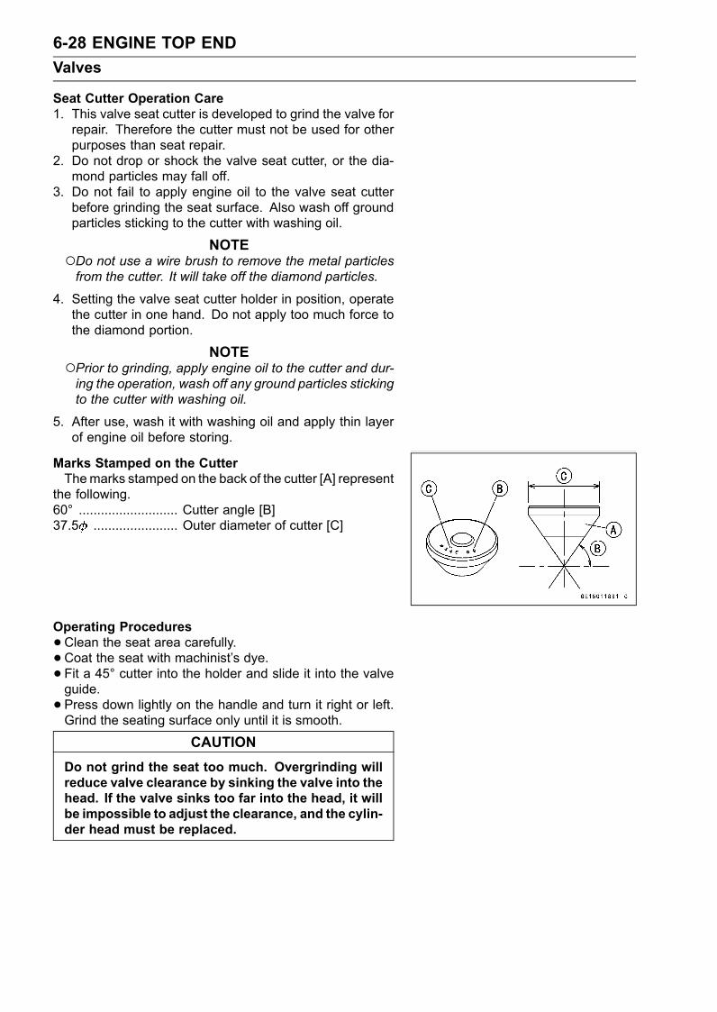
6-28 ENGINE TOP ENDValves
Seat Cutter Operation Care1. This valve seat cutter is developed to grind the valve forrepair. Therefore the cutter must not be used for otherpurposes than seat repair.
2. Do not drop or shock the valve seat cutter, or the dia-mond particles may fall off.
3. Do not fail to apply engine oil to the valve seat cutterbefore grinding the seat surface. Also wash off groundparticles sticking to the cutter with washing oil.
NOTEDo not use a wire brush to remove the metal particlesfrom the cutter. It will take off the diamond particles.
4. Setting the valve seat cutter holder in position, operatethe cutter in one hand. Do not apply too much force tothe diamond portion.
NOTEPrior to grinding, apply engine oil to the cutter and dur-ing the operation, wash off any ground particles stickingto the cutter with washing oil.
5. After use, wash it with washing oil and apply thin layerof engine oil before storing.
Marks Stamped on the CutterThemarks stamped on the back of the cutter [A] represent
the following.60° ........................... Cutter angle [B]37.5 ....................... Outer diameter of cutter [C]
Operating Procedures•Clean the seat area carefully.• Coat the seat with machinist’s dye.• Fit a 45° cutter into the holder and slide it into the valveguide.• Press down lightly on the handle and turn it right or left.Grind the seating surface only until it is smooth.
CAUTIONDo not grind the seat too much. Overgrinding willreduce valve clearance by sinking the valve into thehead. If the valve sinks too far into the head, it willbe impossible to adjust the clearance, and the cylin-der head must be replaced.

ENGINE TOP END 6-29Valves
•Measure the outside diameter of the seating surface witha vernier caliper.If the outside diameter of the seating surface is too small,repeat the 45° grind until the diameter is within the spec-ified range.Widened Width [A] of engagement by machining with45° cutterGround Volume [B] by 32° cutter32° [C]Correct Width [D]Ground Volume [E] by 60° or 55° cutter60° or 55° [F]
•Measure the outside diameter of the seating surface witha vernier caliper.If the outside diameter of the seating surface is too small,repeat the 45° grind [A] until the diameter is within thespecified range.Original Seating Surface [B]
NOTERemove all pittings of flaws from 45° ground surface.After grinding with 45° cutter, apply thin coat of machin-ist’s dye to seating surface. This makes seating surfacedistinct and 32° and 60° grinding operation easier.When the valve guide is replaced, be sure to grind with45° cutter for centering and good contact.
If the outside diameter [A] of the seating surface is toolarge, make the 32° grind described below.If the outside diameter of the seating surface is within thespecified range, measure the seat width as described be-low.•Grind the seat at a 32° angle [B] until the seat O.D. iswithin the specified range.To make the 32° grind, fit a 32° cutter into the holder, andslide it into the valve guide.Turn the holder one turn at a time while pressing downvery lightly. Check the seat after each turn.
CAUTIONThe 32° cutter removes material very quickly.Check the seat outside diameter frequently to pre-vent overgrinding.
After making the 32° grind, return to the seat O.D. mea-surement step above.• To measure the seat width, use a vernier caliper to mea-sure the width of the 45° angle portion of the seat at sev-eral places around the seat.If the seat width is too narrow, repeat the 45° grind untilthe seat is slightly too wide, and then return to the seatO.D. measurement step above.

6-30 ENGINE TOP ENDValves
If the seat width is too wide, make the 60° or 55° [A] grinddescribed below.If the seat width is within the specified range, lap the valveto the seat as described below.•Grind the seat at a 60° or 55° angle until the seat width iswithin the specified range.To make the 60° or 55° grind, fit 60° or 55° cutter into theholder, and slide it into the valve guide.Turn the holder, while pressing down lightly.After making the 60° or 55° grind, return to the seat widthmeasurement step above.Correct Width [B]
• Lap the valve to the seat, once the seat width and O.D.are within the ranges specified above.Put a little coarse grinding compound on the face of thevalve in a number of places around the valve head.Spin the valve against the seat until the grinding com-pound produces a smooth, matched surface on both theseat and the valve.Repeat the process with a fine grinding compound.[A] Lapper[B] Valve Seat[C] Valve• The seating area should be marked about in the middleof the valve face.If the seat area is not in the right place on the valve, checkto be sure the valve is the correct part. If it is, it may havebeen refaced too much; replace it.• Be sure to remove all grinding compound before assem-bly.•When the engine is assembled, be sure to adjust the valveclearance (see Valve Clearance Adjustment section ofPeriodic Maintenance chapter).
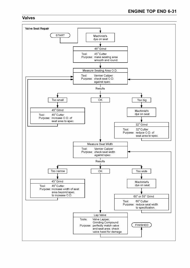
ENGINE TOP END 6-31Valves

6-32 ENGINE TOP ENDCylinder, Pistons
Cylinder Removal•Drain the engine oil (see Periodic Maintenance chapter).• Remove:Engine (see Engine Removal/Installation chapter)Cylinder Head (see Cylinder Head Removal)Dipstick Tube Bolts [A]Dipstick Tube [B]
• Remove:Breather Case Mounting Bolts [A]Clamp [B]Breather Case [C] (with Hose)Oil Hose [D]
• Remove:Camshaft Chain Guide Bolts [A]Camshaft Chain Guide [B]Cylinder [C]
Piston Removal•Remove the cylinder (see Cylinder Removal).• Place a clean cloth under the pistons and remove the pis-ton pin snap ring [A] from the outside of each piston.
CAUTIONDo not reuse the snap rings, as removal weakensand deforms them. They fall out and score the cylin-der wall.
•Remove the piston pins with a piston pin puller [A].Special Tool - Piston Pin Puller Assembly: 57001-910
•Remove the pistons.

ENGINE TOP END 6-33Cylinder, Pistons
•Carefully spread the ring opening with your thumbs andthen push up on the opposite side of the ring [A] to removeit.• Remove the 3-piece oil ring with your thumbs in the samemanner.
Piston/Cylinder InstallationNOTE
If a new cylinder is used, use new piston rings.If new pistons and/or a new cylinder are installed, applythin coat of molybdenum disulfide oil solution to the newpistons and cylinder bores.
• Install the oil ring expander [A] in the bottom piston ringgroove so the ends [B] butt together.• Install the oil ring steel rails, one above the expander andone below it.Spread the rail with your thumbs, but only enough to fitthe rail over the piston.Release the rail into the bottom piston ring groove.
NOTEThe oil ring rails have no “top” or “bottom”.•Do not mix up the top and second ring.• Install the top ring [A] so that the "R" mark [B] faces up.Install the second ring [C] so that the "RN" mark [D] facesup.Apply molybdenum disulfide oil solution to the pistonrings.
NOTEIf a new piston is used, use new piston ring.• Install the piston with its marking hollow facing exhaustside.• Fit a new piston pin snap ring into the side of the pistonso that the ring opening [A] does not coincide with the slit[B] of the piston pin hole.Apply molybdenum disulfide oil solution to the piston pinsand piston journals.When installing the piston pin snap ring, compress it onlyenough to install it and no more.
CAUTIONDo not reuse snap rings, as removal weakens anddeforms them.They could fall out and score the cylinder wall.

6-34 ENGINE TOP ENDCylinder, Pistons
•The piston ring openings must be positioned as shown inthe figure. The openings of the oil ring steel rails must beabout 30 ∼ 40° of angle from the opening of the top ring.[A] Top Ring[B] Second Ring[C] Oil Ring Steel Rails[D] Oil Ring Expander[E] Hollow (Exhaust Side)
• Replace the cylinder gasket with a new one, and installthe pins [A] and new cylinder gasket.Exhaust Side [B]• Apply molybdenum disulfide oil solution to the cylinderbore, external of pistons and piston rings.
• Insert the piston in the cylinder by two methods.With the Hand•Position the crankshaft at #2, #3 piston TDC.• Install the two cylinder head bolts [A] diagonally in thecrankcase.• Install the cylinder block [B].Pistons [C]
First insert the #2, #3 pistons, and then rotate the crank-shaft at 90° angle.Insert the piston rings with your thumbs or the thin (–)screw driver.
With the Special Tools• Install the two cylinder head bolts [A] diagonally in thecrankcase.• Slip the piston bases [B] under the pistons to hold themlevel.• Compress the piston rings using the piston ring compres-sor grips [C] and piston ring compressor belts [D] withchamfered side upward.Special Tools - Piston Base, 8: 57001-1604
Piston Ring Compressor Grip: 57001-1095Piston Ring Compressor Belt, 80 ∼ 91:57001-1320
•Push down vigorously the cylinder aligning the cylinderbores with all the piston heads.• Install the cylinder so that its angle aligns the piston angleafter removing the piston ring compressor belts.• Install the removed parts.

ENGINE TOP END 6-35Cylinder, Pistons
Cylinder Wear•Since there is a difference in cylinder wear in different di-rections, take a side-to-side and a front-to-back measure-ment at each of the two locations (total of four measure-ments) shown in the figure.If any of the cylinder inside diameter measurements ex-ceeds the service limit, replace the cylinder.[A] 10 mm (0.39 in.)[B] 60 mm (2.36 in.)
Cylinder Inside DiameterStandard: 82.994 ∼ 83.006 mm (3.2675 ∼ 3.2679 in.)Service Limit: 83.10 mm (3.272 in.)
Piston Wear•Measure the outside diameter [A] of each piston 18 mm(0.71 in.) [B] up from the bottom of the piston at a rightangle to the direction of the piston pin.If the measurement is less than the service limit, replacethe piston.
Piston DiameterStandard: 82.919 ∼ 82.934 mm (3.2645 ∼ 3.2651 in.)Service Limit: 82.77 mm (3.259 in.)
Piston Ring, Piston Ring Groove Wear•Check for uneven groovewear by inspecting the ring seat-ing.The rings should fit perfectly parallel to groove surfaces.If not, replace the piston and all the piston rings.•With the piston rings in their grooves, make several mea-surements with a thickness gauge [A] to determine pistonring/groove clearance.
Piston Ring/Groove ClearanceStandard:Top 0.03 ∼ 0.07 mm (0.0012 ∼ 0.0028 in.)Second 0.02 ∼ 0.06 mm (0.0008 ∼ 0.0024 in.)
Service Limit:Top 0.17 mm (0.0067 in.)Second 0.16 mm (0.0063 in.)
Piston Ring Groove Width•Measure the piston ring groove width.Use a vernier caliper at several points around the piston.
Standard:Top [A] 0.92 ∼ 0.94 mm (0.0362 ∼ 0.0370 in.)Second [B] 1.01 ∼ 1.03 mm (0.0398 ∼ 0.0406 in.)
Service Limit:Top [A] 1.02 mm (0.0402 in.)Second [B] 1.11 mm (0.0437 in.)
If the width of any of the two grooves is wider than theservice limit at any point, replace the piston.

6-36 ENGINE TOP ENDCylinder, Pistons
Piston Ring Thickness•Measure the piston ring thickness.Use the micrometer to measure at several points aroundthe ring.
Piston Ring ThicknessStandard:Top [A] 0.87 ∼ 0.89 mm (0.0343 ∼ 0.0350 in.)Second [B] 0.97 ∼ 0.99 mm (0.0382 ∼ 0.0390 in.)
Service Limit:Top [A] 0.80 mm (0.0315 in.)Second [B] 0.90 mm (0.0354 in.)
If any of the measurements is less than the service limiton either of the rings, replace all the rings.
NOTEWhen using new rings in a used piston, check for un-even groove wear. The rings should fit perfectly parallelto the groove sides. If not, replace the piston.
Piston Ring End Gap•Place the piston ring [A] inside the cylinder, using the pis-ton to locate the ring squarely in place. Set it close to thebottom of the cylinder, where cylinder wear is low.•Measure the gap between the ends of the ring with a thick-ness gauge [B].
Piston Ring End GapStandard:Top 0.25 ∼ 0.40 mm (0.0098 ∼ 0.0157 in.)Second 0.40 ∼ 0.55 mm (0.0157 ∼ 0.0217 in.)
Service Limit:Top 0.7 mm (0.0276 in.)Second 0.8 mm (0.0315 in.)
If the end gap of either ring is greater than the servicelimit, replace all the rings.

ENGINE REMOVAL/INSTALLATION 7-1
7
Engine Removal/InstallationTable of Contents
Exploded View........................................................................................................................ 7-2Engine Removal/Installation ................................................................................................... 7-4
Engine Removal................................................................................................................ 7-4Engine Damper Removal.................................................................................................. 7-6Engine Damper Installation............................................................................................... 7-6Engine Installation............................................................................................................. 7-6

7-2 ENGINE REMOVAL/INSTALLATIONExploded View

ENGINE REMOVAL/INSTALLATION 7-3Exploded View
TorqueNo Fastener
N·m kgf·m ft·lbRemarks
1 Engine Mounting Bolts 36 3.7 27 L2 Engine Damper Mounting Bolts 16 1.6 12 LL: Apply a non-permanent locking agent.

7-4 ENGINE REMOVAL/INSTALLATIONEngine Removal/Installation
Engine Removal•Remove:Seat (see Seat Removal in the Hull/Engine Hood chap-ter)Rear Grip Plate (see Rear Grip Plate Removal in theHull/Engine Hood chapter)Oil Separator Tank (see Oil Separator Tank Removal inthe Engine Lubrication System chapter)• Plug the hose end [A].If the engine is disassembled, drain the oil (see EngineOil Change in the Periodic Maintenance chapter).• Remove:Air Filter (see Air Filter Removal in the Fuel System (DFI)chapter)Inlet Manifold (see Inlet Manifold Removal in the FuelSystem (DFI) chapter)Exhaust Manifold (see Exhaust Manifold Removal in theExhaust System chapter)
• Remove:Cooling Hoses [A]
The oil hose [B] is not necessary removal.NOTE
If the oil is in the engine and the removed hose liesdown, the oil will flow out from hose end.
•Remove:Coupling Cover Bolts [A]Coupling Cover [B]Cooling Hose [C]
• Remove:Starter Motor Cables [A]Battery (–) Cable [B]Cooling Hoses [C]Oil Pressure Switch Connector [D]

ENGINE REMOVAL/INSTALLATION 7-5Engine Removal/Installation
•Disconnect:Oil Temperature Sensor Connector [A]
• Remove:Engine Mounting Bolts [A]
• Slide the engine toward the front to disengage the cou-pling [A].
• Using the lifter [A], raise the front side of the engine a littleand lift the engine [B] out off the hull [C].
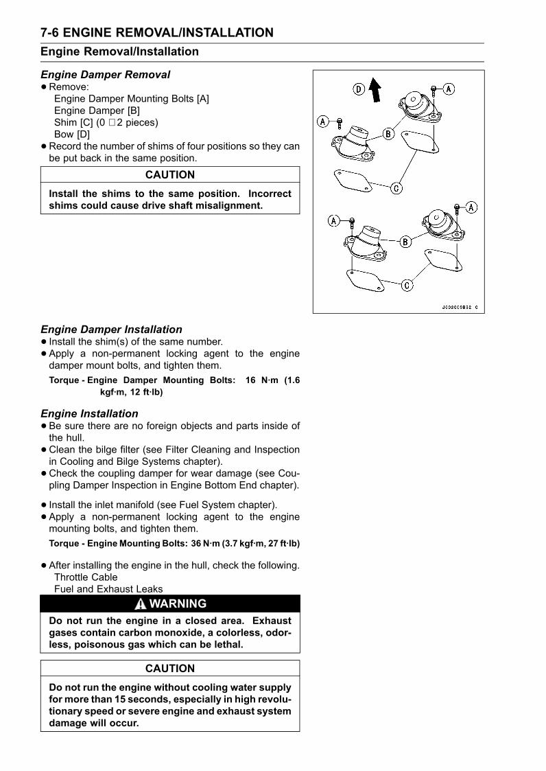
7-6 ENGINE REMOVAL/INSTALLATIONEngine Removal/Installation
Engine Damper Removal•Remove:Engine Damper Mounting Bolts [A]Engine Damper [B]Shim [C] (0 ∼ 2 pieces)Bow [D]•Record the number of shims of four positions so they canbe put back in the same position.
CAUTIONInstall the shims to the same position. Incorrectshims could cause drive shaft misalignment.
Engine Damper Installation• Install the shim(s) of the same number.• Apply a non-permanent locking agent to the enginedamper mount bolts, and tighten them.Torque - Engine Damper Mounting Bolts: 16 N·m (1.6
kgf·m, 12 ft·lb)
Engine Installation•Be sure there are no foreign objects and parts inside ofthe hull.• Clean the bilge filter (see Filter Cleaning and Inspectionin Cooling and Bilge Systems chapter).• Check the coupling damper for wear damage (see Cou-pling Damper Inspection in Engine Bottom End chapter).
• Install the inlet manifold (see Fuel System chapter).• Apply a non-permanent locking agent to the enginemounting bolts, and tighten them.Torque - EngineMounting Bolts: 36 N·m (3.7 kgf·m, 27 ft·lb)
•After installing the engine in the hull, check the following.Throttle CableFuel and Exhaust Leaks
WARNINGDo not run the engine in a closed area. Exhaustgases contain carbon monoxide, a colorless, odor-less, poisonous gas which can be lethal.
CAUTIONDo not run the engine without cooling water supplyfor more than 15 seconds, especially in high revolu-tionary speed or severe engine and exhaust systemdamage will occur.
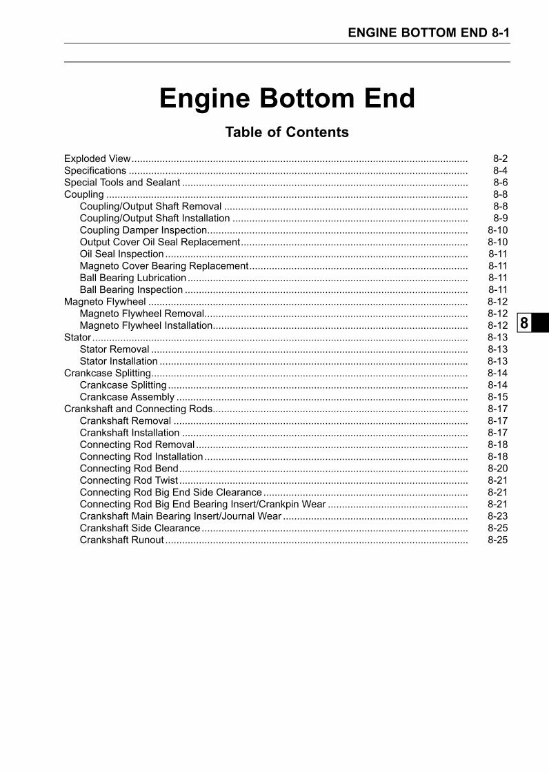
ENGINE BOTTOM END 8-1
8
Engine Bottom EndTable of Contents
Exploded View........................................................................................................................ 8-2Specifications ......................................................................................................................... 8-4Special Tools and Sealant ...................................................................................................... 8-6Coupling ................................................................................................................................. 8-8
Coupling/Output Shaft Removal ....................................................................................... 8-8Coupling/Output Shaft Installation .................................................................................... 8-9Coupling Damper Inspection............................................................................................. 8-10Output Cover Oil Seal Replacement................................................................................. 8-10Oil Seal Inspection ............................................................................................................ 8-11Magneto Cover Bearing Replacement.............................................................................. 8-11Ball Bearing Lubrication .................................................................................................... 8-11Ball Bearing Inspection ..................................................................................................... 8-11
Magneto Flywheel .................................................................................................................. 8-12Magneto Flywheel Removal.............................................................................................. 8-12Magneto Flywheel Installation........................................................................................... 8-12
Stator ...................................................................................................................................... 8-13Stator Removal ................................................................................................................. 8-13Stator Installation .............................................................................................................. 8-13
Crankcase Splitting................................................................................................................. 8-14Crankcase Splitting ........................................................................................................... 8-14Crankcase Assembly ........................................................................................................ 8-15
Crankshaft and Connecting Rods........................................................................................... 8-17Crankshaft Removal ......................................................................................................... 8-17Crankshaft Installation ...................................................................................................... 8-17Connecting Rod Removal ................................................................................................. 8-18Connecting Rod Installation .............................................................................................. 8-18Connecting Rod Bend....................................................................................................... 8-20Connecting Rod Twist ....................................................................................................... 8-21Connecting Rod Big End Side Clearance ......................................................................... 8-21Connecting Rod Big End Bearing Insert/Crankpin Wear .................................................. 8-21Crankshaft Main Bearing Insert/Journal Wear .................................................................. 8-23Crankshaft Side Clearance............................................................................................... 8-25Crankshaft Runout ............................................................................................................ 8-25

8-2 ENGINE BOTTOM ENDExploded View

ENGINE BOTTOM END 8-3Exploded View
TorqueNo. Fastener
N·m kgf·m ft·lbRemarks
1 Crankshaft Sensor Cover Bolts 7.8 0.80 69 in·lb2 Engine Bracket Mounting Bolts 32 3.3 24 L3 Timing Rotor Bolt 20 2.0 14 L4 Connecting Rod Nuts – – – MO, see text5 Oil Passage Plugs 20 2.0 14 L6 Stator Mounting Bolts 12 1.2 104 in·lb L7 Grommet Cover Bolts 9.8 1.0 87 in·lb L8 Magneto Cover Bolts 20 2.0 149 Output Cover Bolts 7.8 0.80 69 in·lb10 Output Shaft 245 25.0 180 MO11 Coupling 110 11 8112 Crankcase Bolts (M10) 50 5.0 36 MO, S13 Crankcase Bolts (M8) 29 3.0 22 MO, S14 Crankcase Bolts (M8) 29 3.0 22 S15 Crankcase Bolts (M6) 12 1.2 104 in·lb SD: Do not apply any grease or oil.G: Apply grease.L: Apply a non-permanent locking agent.
LG: Apply liquid gasket (Kawasaki Bond: 92104-1062).M: Apply molybdenum disulfide grease.
MO: Apply molybdenum disulfide oil solution (mixture of the engine oil and molybdenum disulfidegrease in a weight ratio 10 : 1).
R: Replacement Parts.S: Follow the specific tightening sequence.SS: Apply silicone sealant.WG: Apply water resistant grease.

8-4 ENGINE BOTTOM ENDSpecifications
Item Standard Service LimitCrankshaft, Connecting RodsConnecting Rod Bend – – – 0.2/100 mm
(0.008/3.94 in.)Connecting Rod Twist – – – 0.2/100 mm
(0.008/3.94 in.)Connecting Rod Big End Side Clearance 0.13 ∼ 0.38 mm
(0.0051 ∼ 0.0150 in.)0.58 mm(0.023 in.)
Connecting Rod Big end BearingInsert/crankpin Clearance
0.041 ∼ 0.071 mm(0.0016 ∼ 0.0028 in.)
0.11 mm(0.0043 in.)
Crankpin Diameter: 38.984 ∼ 39.000 mm(1.5348 ∼ 1.5354 in.)
38.97 mm(1.534 in.)
Marking:None 38.984 ∼ 38.992 mm
(1.5348 ∼ 1.5351 in.)– – –
38.993 ∼ 39.000 mm(1.5352 ∼ 1.5354 in.)
– – –
Connecting Rod Big End Bore Diameter: 42.000 ∼ 42.016 mm(1.6535 ∼ 1.6542 in.)
– – –
MarkingNone 42.000 ∼ 42.008 mm
(1.6535 ∼ 1.65386 in.)– – –
42.009 ∼ 42.016 mm(1.65389 ∼ 1.6542 in.)
– – –
Connecting Rod Big End Bearing InsertThickness:Brown 1.475 ∼ 1.480 mm
(0.05807 ∼ 0.05827 in.)– – –
Black 1.480 ∼ 1.485 mm(0.05827 ∼ 0.05846 in.)
– – –
Blue 1.485 ∼ 1.490 mm(0.05846 ∼ 0.05866 in.)
– – –
Connecting Rod Big End Bearing Insert Selection
Bearing InsertCon-rod BigEnd BoreDiameterMarking
CrankpinDiameterMarking Size Color Part Number
None Brown 92139-3710None None Black 92139-3709
None Blue 92139-3708
Crankshaft Side Clearance 0.05 ∼ 0.24 mm(0.0020 ∼ 0.0094 in.)
0.44 mm(0.017 in.)
Crankshaft Runout TIR 0.03 mm (0.0012 in.) or less TIR 0.07 mm(0.0028 in.)
Crankshaft Main Bearing Insert/journalClearance
0.030 ∼ 0.054 mm(0.0012 ∼ 0.0021 in.)
0.08 mm(0.0032 in.)

ENGINE BOTTOM END 8-5Specifications
Item Standard Service LimitCrankshaft Main Journal Diameter: 40.984 ∼ 41.000 mm
(1.6135 ∼ 1.6142 in.)40.96 mm(1.613 in.)
MarkingNone 40.984 ∼ 40.992 mm
(1.6135 ∼ 1.61385 in.)– – –
1 40.993 ∼ 41.000 mm(1.61389 ∼ 1.6142 in.)
– – –
Crankcase Main Bearing Bore Diameter: 44.000 ∼ 44.016 mm(1.7323 ∼ 1.7329 in.)
– – –
Marking 44.000 ∼ 44.008 mm
(1.7323 ∼ 1.73259 in.)– – –
None 44.009 ∼ 44.016 mm(1.73263 ∼ 1.7329 in.)
– – –
Crankshaft Main Bearing Insert Thickness:Brown 1.490 ∼ 1.494 mm
(0.05866 ∼ 0.05882 in.)– – –
Black 1.494 ∼ 1.498 mm(0.05882 ∼ 0.05898 in.)
– – –
Blue1.498 ∼ 1.502 mm(0.05898 ∼ 0.05913 in.)
– – –
Crankshaft Main Bearing Insert Selection
Bearing Insert*CrankcaseMain BearingBore DiameterMarking
CrankshaftMain JournalDiameterMarking
Size Color Part Number Journal Nos.
92139-3704 1, 592139-3713 3 1 Brown92139-3707 2, 4
None 92139-3703 1, 592139-3712 3
None 1Black
92139-3706 2, 492139-3702 1, 592139-3711 3None None Blue92139-3705 2, 4
*The bearing inserts for Nos. 2 and 4 journals have an oil groove, respectively.
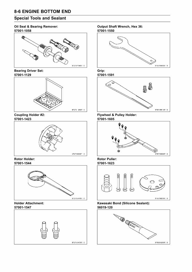
8-6 ENGINE BOTTOM ENDSpecial Tools and Sealant
Oil Seal & Bearing Remover:57001-1058
Bearing Driver Set:57001-1129
Coupling Holder #2:57001-1423
Rotor Holder:57001-1544
Holder Attachment:57001-1547
Output Shaft Wrench, Hex 36:57001-1550
Grip:57001-1591
Flywheel & Pulley Holder:57001-1605
Rotor Puller:57001-1623
Kawasaki Bond (Silicone Sealant):56019-120

ENGINE BOTTOM END 8-7Special Tools and Sealant
Kawasaki Bond (Liquid Gasket - Black):92104-1062

8-8 ENGINE BOTTOM ENDCoupling
Coupling/Output Shaft Removal•Remove:Engine (see Engine Removal/Installation chapter)Crankshaft Sensor Cover (see Electrical System chap-ter)• Holding the timing rotor, unscrew the coupling.Special Tools - Flywheel & Pulley Holder: 57001-1605 [A]
Holder Attachment: 57001-1547 [B]Coupling Holder #2: 57001-1423 [C]
If the coupling [A] and output shaft [B] removed together,holding the coupling, unscrew the output shaft with theoutput shaft wrench [C].Collar [D]Special Tool - Output Shaft Wrench, Hex 36: 57001-1550
•Remove:Output Cover Bolts [A]Output Cover [B]
• Remove:Magneto Cover Bolts [C]Magneto Cover

ENGINE BOTTOM END 8-9Coupling
•Using the rotor holder [A], remove the output shaft [B].Special Tool - Rotor Holder: 57001-1544
Coupling/Output Shaft Installation•Applymolybdenum disulfide oil solution to the seating sur-face of the output shaft.• Using the rotor holder [A], install the output shaft [B].Special Tool - Rotor Holder: 57001-1544
Torque - Output Shaft: 245 N·m (25.0 kgf·m, 180 ft·lb)
•Apply silicone sealant [A] to the crankcase halves matingsurfaces on the magneto cover.• Be sure to install the dowel pins [B].
• Apply grease to the O-ring [A], and fit the O-ring onto thegroove of the magneto cover [B].• Install the magneto cover.Be sure to install the washer [C] and the spring [D] intothe hole [E] of the bushing.Torque - Magneto Cover Bolts: 20 N·m (2.0 kgf·m, 14 ft·lb)
•Apply grease to the O-ring [A] and collar inside.• Install the collar [B] so that the chamfer side [C] facesinward.

8-10 ENGINE BOTTOM ENDCoupling
• Install:Pins [A]Gasket [B]• Position the magnet lead [C] as shown.
• Apply grease to the oil seal lip.• Install the output cover.Run the magneto lead [A] between the magneto cover [B]and the output cover [C] as shown.Torque - Output Cover Bolts: 7.8 N·m (0.80 kgf·m, 69 in·lb)
• Install the coupling by using the old timing rotor as a hold-ing tool.Special Tools - Flywheel & Pulley Holder: 57001-1605
Holder Attachment: 57001-1547Coupling Holder #2: 57001-1423
Torque - Coupling: 110 N·m (11 kgf·m, 81 ft·lb)
•Then remove the timing rotor. This removed rotorshould be stored as a special tool by grinding theprojection or marking an adequate mark for verifying.• Then install one new timing rotor [A]. Use the following asa new part.
Model Name Part No.JT1500C7F 21007-3744
Coupling Damper Inspection•Refer to Coupling Damper Inspection in the PeriodicMaintenance chapter.
Output Cover Oil Seal Replacement•Remove:Output Cover (see Coupling/Output Shaft Removal)• Using the bearing driver [A], remove the oil seals as a set.Special Tool - Bearing Driver Set: 57001-1129

ENGINE BOTTOM END 8-11Coupling
•Replace the oil seals with new ones.• Apply thin coat grease to the oil seal lips [A].• Pack grease [B] between the oil seal lip and housing ofthe oil seal (flywheel side oil seal [C]).• Press in the oil seals until they are bottomed.Install the coupling oil seal [D] so that the manufacturer’smarks [E] face coupling side.Install the flywheel side oil seal so that the dust seal [F]side face out.
Oil Seal Inspection• Inspect the oil seal.Replace it if the lips are misshapen, discolored (indicatingthat the rubber has deteriorated), hardened or otherwisedamaged.
Magneto Cover Bearing ReplacementCAUTION
Do not remove the ball bearing unless it is neces-sary. Removal may damage it.
•Remove:Magneto Cover (see Coupling/Output Shaft Removal)• Using the oil seal and bearing remover [A], remove theball bearing from the magneto cover [B].When removing the ball bearing, hold the magneto cover.Special Tool - Oil Seal and Bearing Remover: 57001-1058
•Using a press and the bearing driver set [A], install thenew bearing until it stops at the bottom of its housing.Special Tool - Bearing Driver Set: 57001-1129
Ball Bearing LubricationNOTE
Since the bearings are packed with grease and sealedon both sides, lubrication is not required.
Ball Bearing InspectionNOTE
It is not necessary to remove the bearings for inspec-tion. If the bearing is removed, it will need to be re-placed with a new one.
•Spin [A] it by hand to check its condition.If it is noisy, does not spin smoothly, or has any roughspots, it must be replaced.• Examine the bearing seal [B] for tears or leakage.If the seal is torn or is leaking, replace the bearing.

8-12 ENGINE BOTTOM ENDMagneto Flywheel
Magneto Flywheel Removal•Remove:Engine (see Engine Removal/Installation chapter)Crankshaft Sensor Cover (see Electrical System chap-ter)Coupling (see Coupling/Output Shaft Removal)Magneto Cover (see Coupling/Output Shaft Removal)
Using the rotor puller [A], pull off the flywheel [B].Special Tool - Rotor Puller: 57001-1623
Grip: 57001-1591 [C]
CAUTIONDo not hit the head of the rotor puller. A loss in rotormagnetism may be caused.
Magneto Flywheel Installation•Using a high-flash points solvents, clean off any oil or dirtthat may be on the crankshaft taper, and in the taperedhole in the magneto flywheel.• Install the O-ring [A] directly as shown.This face [C] is magneto flywheel side.If the reduction gear [D] is removed, apply a molybdenumdisulfide grease to both ends of its shaft.• Install the reduction gear and the washer [E].
• Apply grease to the boss outside [A] of the magneto fly-wheel [B].10 mm (0.39 in.) [C]• Install the magneto flywheel.
NOTEConfirm the magneto flywheel fit or not to the crankshaftbefore tightening it with specified torque.
Install the output shaft and tighten it with 70 N·m (7.0kgf·m, 52 ft·lb) of torque.Remove the output shaft.Check the tightening torque with rotor puller.Special Tool - Rotor Puller: 57001-1623
Grip: 57001-1591If the magneto flywheel is not pulled out with 20 N·m (2.0kgf·m, 52 ft·lb) of drawing torque, it is installed correctly.If the magneto flywheel is pulled out with under 20 N·m(2.0 kgf·m, 52 ft·lb) of drawing torque, clean off any oil dirtor flaw of the crankshaft and magneto flywheel taperedportion, and dry them with a clean cloth. Then, confirmthat it is not pulled out with above torque.• Tighten the output shaft while holding the magneto fly-wheel steady with the rotor holder.Special Tool - Rotor Holder: 57001-1544
Torque - Output Shaft: 245 N·m (25 kgf·m, 180 ft·lb)
• Install:Magneto Cover (see Coupling/Output Shaft Installation)

ENGINE BOTTOM END 8-13Stator
Stator Removal•Remove:Engine (see Engine Removal/Installation chapter)Magneto Cover (see Coupling/Output Shaft Removal)Grommet Cover Mounting Bolts [A]Grommet Cover [B]Stator Mounting Bolts [C] with WashersStator Assembly [D]
Stator Installation•Apply water resistant grease to the outside of the grom-met.• Apply a non-permanent locking agent to the grommetcover bolts.• Tighten:Torque - Grommet Cover Bolts: 9.8 N·m (1.0 kgf·m, 87 in·lb)
•Apply a non-permanent locking agent to the stator mount-ing bolts and put the washers.• Tighten:Torque - Stator Mounting Bolts: 12 N·m (1.2 kgf·m, 104
in·lb)
When installing the stator, fix the stator lead to the grooveof the magneto cover.Be sure to the stator lead have no slack and bite.
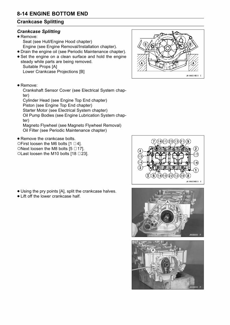
8-14 ENGINE BOTTOM ENDCrankcase Splitting
Crankcase Splitting•Remove:Seat (see Hull/Engine Hood chapter)Engine (see Engine Removal/Installation chapter).• Drain the engine oil (see Periodic Maintenance chapter).• Set the engine on a clean surface and hold the enginesteady while parts are being removed.Suitable Props [A]Lower Crankcase Projections [B]
• Remove:Crankshaft Sensor Cover (see Electrical System chap-ter)Cylinder Head (see Engine Top End chapter)Piston (see Engine Top End chapter)Starter Motor (see Electrical System chapter)Oil Pump Bodies (see Engine Lubrication System chap-ter)Magneto Flywheel (see Magneto Flywheel Removal)Oil Filter (see Periodic Maintenance chapter)
• Remove the crankcase bolts.First loosen the M6 bolts [1 ∼ 4].Next loosen the M8 bolts [5 ∼ 17].Last loosen the M10 bolts [18 ∼ 23].
• Using the pry points [A], split the crankcase halves.• Lift off the lower crankcase half.

ENGINE BOTTOM END 8-15Crankcase Splitting
Crankcase AssemblyCAUTION
The upper and lower crankcase halves are ma-chined at the factory in the assembled state, so thecrankcase halves must be replaced as a set.
•With high-flash point solvent, clean off the mating sur-faces of the crankcases halves and wipe dry.• Using compressed air, blow out the oil passages in thecrankcase halves.
• Install:Crankshaft [A] and Connecting Rods (see CrankshaftInstallation)Camshaft Chain [B]Oil Pump Sprocket Chain [C]Dowel Pins [D]Oil Passage Pipe [E] with O-ringOil Seal [F]
• Before fitting the lower case on the upper case, check thefollowing.Be sure to hang the camshaft and oil pump sprocket chainon the crankshaft.Check to see that the oil seal [A] is in the groove [B] of thecrankcase.
• Apply liquid gasket [A] to the mating surface of the lowercrankcase half.
NOTEMake the application finish within 30 minutes whenthe liquid gasket to the mating surface of the lowercrankcase half is applied.Moreover fit the case and tighten the case bolts justafter finishing the application of the liquid gasket.
Sealant - Kawasaki Bond: 92104-1062
CAUTIONDo not apply liquid gasket around the crankshaftmain bearing inserts [B], and oil passage hole [C].

8-16 ENGINE BOTTOM ENDCrankcase Splitting
• Install the oil pump sprocket chain [A] on the chain guide[B] of the lower crankcase [C].
• Apply molybdenum disulfide oil solution to the bolt seatingsurfaces [A] on the lower crankcase for the M10 bolts [B]and M8 [7 ∼ 10] bolts [C].
• Tighten the crankcase bolts.Following the sequence numbers on the lower crankcasehalf, tighten the M10 bolts [1 ∼ 6].Torque - Crankcase Bolts (M10): 50 N·m (5.0 kgf·m, 36 ft·lb)Following the sequence numbers, tighten the M8 bolts [7
∼ 10].Torque - Crankcase Bolts (M8): 29 N·m (3.0 kgf·m, 22 ft·lb)Following the sequence numbers, tighten the M8 bolts [11
∼ 19].Torque - Crankcase Bolts (M8): 29 N·m (3.0 kgf·m, 22 ft·lb)Following the sequence numbers, tighten theM7 bolts [20
∼ 23].Torque - Crankcase Bolts (M6): 12 N·m (1.2 kgf·m, 104 in·lb)
•After tightening all crankcase bolts, check the followingitem.Crankshaft turn freely.

ENGINE BOTTOM END 8-17Crankshaft and Connecting Rods
Crankshaft Removal•Split the crankcase (see Crankcase Splitting).• Remove:Camshaft Chain [A]Oil Pump Sprocket Chain [B]• Remove the crankshaft [C] with the oil seal [D].
Crankshaft InstallationCAUTION
If the crankshaft, bearing inserts, or crankcasehalves are replaced with new ones, select the bear-ing inserts and check clearance with a plastigagebefore assembling engine to be sure the correctbearing inserts are installed.
•Fit the crankshaft main bearing inserts on the upper [A]and lower [B] crankcase halves.#1, 5 Bearing Inserts (no Groove, same)#2, 4 Bearing Inserts (Groove, same)#3 Bearing Insert (no Groove)
NOTEBe sure the bearing inserts are seated in the saddles,and the tangs in the bearing inserts are aligned with thenotches in the saddles.
•Apply molybdenum disulfide oil solution to the crankshaftmain bearing inserts.
• Fit the thrust washers [A] to both sides of the uppercrankcase #3 main bearing [B].Install the thrust washer so that the oil grooves [C] faceoutward.

8-18 ENGINE BOTTOM ENDCrankshaft and Connecting Rods
• Install the crankshaft with the oil pump sprocket chain [A]and camshaft chain [B] hanging on them.
• Fit the oil seal [A] into the groove [B] of the crankcase.• Assemble the crankcase (see Crankcase Assembly).
Connecting Rod Removal•Split the crankcase (see Crankcase Splitting).• Remove the connecting rod nuts [A].• Remove the crankshaft.
NOTEMark and record the locations of the connecting rodsand their big end caps so that they can be reassembledin their original positions.
•Remove the connecting rods from the crankshaft.
Connecting Rod InstallationWARNING
Clean the crankshaft, bolts, nuts, and connectingrods in a well-ventilated area, and take care thatthere is no spark or flame anywhere near the work-ing area. This includes any appliance with a pilotlight. Because of the danger of highly flammableliquids, do not use gasoline or low-flash point sol-vents to clean them.
•After removing the connecting rods from the crankshaft,clean them with high-flash point solvent.• Blow the crankshaft oil passages with compressed air toremove any foreign particles or residue that may haveaccumulated in the passages.

ENGINE BOTTOM END 8-19Crankshaft and Connecting Rods
CAUTIONTo minimize vibration, the connecting rods shouldhave the same weight mark.
Big End Cap [A]Connecting Rod [B]Weight Mark, Alphabet [C]Diameter Mark [D]If the connecting rods, big end bearing inserts, or crank-shaft are replaced with new ones, select the bearing insertand check clearance with a plastigage before assemblingengine to be sure the correct bearing inserts are installed.
CAUTIONThe connecting rod bolts are designed to stretchwhen tightened. Never reuse them. See the tablebelow for correct bolt and nut usage.
•Apply grease and oil to the following portions.Apply molybdenum disulfide grease [A].Do not apply grease and oil [B].Apply molybdenum disulfide oil solution [C].
CAUTIONDo not apply grease to the inner surface of the lowerbig end cap or to the outer surface of the lower bear-ing insert.
• Install the bearing insert as shown to prevent its outersurface from scratch damage with connecting rod edge.Connecting Rod Side Bearing Insert [A]Dowel Pin [B]Claw Side [C]Cap Side Bearing Insert [D]Connecting Rod Cap [E]
• Replace the connecting rod big end bolts and nuts withnew ones.• Be sure to clean the bolts, nuts, and connecting rodsthoroughly with high-flash point solvent, because the newconnecting rods, bolts, and nuts are treated with anti-rustsolution.
CAUTIONImmediately dry the bolts and nuts with com-pressed air after cleaning.Clean and dry the bolts and nuts completely.

8-20 ENGINE BOTTOM ENDCrankshaft and Connecting Rods
•Apply small amount of molybdenum disulfide oil solutionto the threads [A] and seating surfaces [B] of the connect-ing rod nuts.
• First, tighten the nuts to the specified torque. See thetable below.•Next, tighten the nuts by 120° more.Mark [A] the connecting rod big end caps and nuts so thatnuts can be turned 120° [B] properly.Tighten the hexagon nut by 2 corners.ConnectingRod Assy Bolt, Nut Torque + Angle N·m
(kgf·m, ft·lb)New Use the bolts and nuts
attached to new con-rod.Another new bolts andnuts.
21.6 (2.2, 16) + 120°
Used Replace the bolts andnuts with new ones
21.6 (2.2, 16) + 120°
CAUTIONBe careful not to overtighten the nuts.
Connecting Rod Bend•Remove the connecting rod big end bearing inserts, andreinstall the connecting rod big end caps.• Select an arbor [A] of the same diameter as the connect-ing rod big end, and insert the arbor through the connect-ing rod big end.• Select an arbor of the same diameter as the piston pinat least 100 mm (3.94 in.) long, and insert the arbor [B]through the connecting rod small end.•On a surface plate, set the big-end arbor on V blocks [C].•Measure the difference in the heights of the arbor abovethe surface plate over a 100 mm (3.94 in.) distance-onthe arbor to determine the amount of connecting rod bendwith the connecting rod held vertically, and using a heightgauge.If connecting rod bend exceeds the service limit, the con-necting rod must be replaced.
Connecting Rod BendService Limit: 0.2/100 mm (0.008/3.94 in.)

ENGINE BOTTOM END 8-21Crankshaft and Connecting Rods
Connecting Rod Twist•On surface plate, set the big-end arbor [A] on V block [C].•Measure the difference in the heights of the arbor [B]above the surface plate over a 100 mm (3.94 in.) dis-tance-on the arbor to determine the amount of connect-ing rod twist with the connecting rod held horizontally, andusing a height gauge.If connecting rod twist exceeds the service limit, the con-necting rod must be replaced.
Connecting Rod TwistService Limit: 0.2/100 mm (0.008/3.94 in.)
Connecting Rod Big End Side Clearance•Measure connecting rod big end side clearance [A].Insert a thickness gauge [B] between the big end and ei-ther crank web to determine clearance.
Connecting Rod Big End Side ClearanceStandard: 0.13 ∼ 0.38 mm (0.0051 ∼ 0.0150 in.)Service Limit: 0.58 mm (0.023 in.)
If the clearance exceeds the service limit, replace the con-necting rod with a new one and then check clearanceagain. If clearance is too large after connecting rod re-placement, the crankshaft also must be replaced.
Connecting Rod Big End Bearing Insert/CrankpinWear•Measure the bearing insert/crankpin [B] clearance with aplastigage [A].
NOTETighten the connecting rod big end nuts to the specifiedtorque (see Connecting Rod Installation).Do not move the connecting rod and crankshaft duringclearance measurement.
Connecting Rod Big End Bearing Insert/CrankpinClearanceStandard: 0.041 ∼ 0.071 mm (0.0016 ∼ 0.00280 in.)Service Limit: 0.11 mm (0.0043 in.)
If clearance is within the standard, no bearing replace-ment is required.If clearance is between 0.072 mm (0.00284 in.) andthe service limit (0.11 mm, 0.0043 in.), replace thebearing inserts [A] with inserts painted blue [B]. Checkinsert/crankpin clearance with the plastigage. The clear-ance may exceed the standard slightly, but it must not beless than the minimum in order to avoid bearing seizure.If the clearance exceeds the service limit, measure thediameter of the crankpins.
Crankpin DiameterStandard: 38.984 ∼ 39.000 mm (1.5348 ∼ 1.5354 in.)Service Limit: 38.97 mm (1.534 in.)

8-22 ENGINE BOTTOM ENDCrankshaft and Connecting Rods
If any crankpin has worn past the service limit, replace thecrankshaft with a new one.If the measured crankpin diameters are not less than theservice limit, but do not coincide with the original diametermarkings on the crankshaft, make new marks on it.
Crankpin Diameter MarksNone 38.984 ∼ 38.992 mm (1.5348 ∼ 1.5351 in.)
38.993 ∼ 39.000 mm (1.5352 ∼ 1.5354 in.)
∆: Crankpin Diameter Marks, “” mark or no mark.
•Measure the connecting rod big end bore diameter, andmark each connecting rod big end in accordance with thebore diameter.Big End Cap [A]Connecting Rod [B]Weight Mark [C]: A letter of the alphabetBore Diameter Mark (Around Weight Mark) [D]: “” orno mark.
NOTETighten the connecting rod big end nuts to the specifiedtorque (see Connecting Rod Installation).Themark already on the big end should almost coincidewith the measurement.
Connecting Rod Big End Bore Diameter MarksNone 42.000 mm ∼ 42.008 mm (1.6535 ∼ 1.65386 in.)
42.009 ∼ 42.016 mm (1.65389 ∼ 1.6542 in.)
•Select the proper bearing insert in accordance with thecombination coding of the connecting rod and crankshaft.• Install the new inserts in the connecting rod and checkinsert/crankpin clearance with the plastigage.
Bearing InsertCon-rod Big EndBore Diameter
Marking
CrankpinDiameterMarking Size Color Part Number
None Brown 92139-3710None None
Black 92139-3709
None Blue 92139-3708

ENGINE BOTTOM END 8-23Crankshaft and Connecting Rods
Crankshaft Main Bearing Insert/Journal Wear•Measure the bearing insert/journal [B] clearance with aplastigage [A].
NOTETighten the crankcase bolts to the specified torque (seeCrankcase Assembly).Do not turn the crankshaft during clearance measure-ment.Journal clearance less than 0.025 mm (0.0010 in.) cannot bemeasured by plastigage, however, using genuineparts maintains the minimum standard clearance.
Crankshaft Main Bearing Insert/Journal ClearanceStandard: 0.030 ∼ 0.054 mm (0.0012 ∼ 0.0021 in.)Service Limit: 0.08 mm (0.0032 in.)
If clearance is within the standard, no bearing replace-ment is required.If clearance is between 0.055 mm (0.022 in.) and the ser-vice limit (0.08 mm, 0.0032 in.), replace the bearing in-serts [A] with inserts painted blue [B]. Check insert/journalclearance with the plastigage. The clearancemay exceedthe standard slightly, but it must not be less than the min-imum in order to avoid bearing seizure.If clearance exceeds the service limit, measure the diam-eter of the crankshaft main journal.
Crankshaft Main Journal DiameterStandard: 40.984 ∼ 41.000 mm (1.6135 ∼ 1.6142 in.)Service Limit: 40.96 mm (1.613 in.)
If any journal has worn past the service limit, replace thecrankshaft with a new one.If the measured journal diameters are not less than theservice limit, but do not coincide with the original diametermarkings on the crankshaft, make new marks on it.
Crankshaft Main Journal Diameter MarksNone 40.984 ∼ 40.992 mm (1.6135 ∼ 1.61385 in.)1 40.993 ∼ 41.000 mm (1.61389 ∼ 1.6142 in.)
: Crankshaft Main Journal Diameter Marks, "1" mark orno mark.
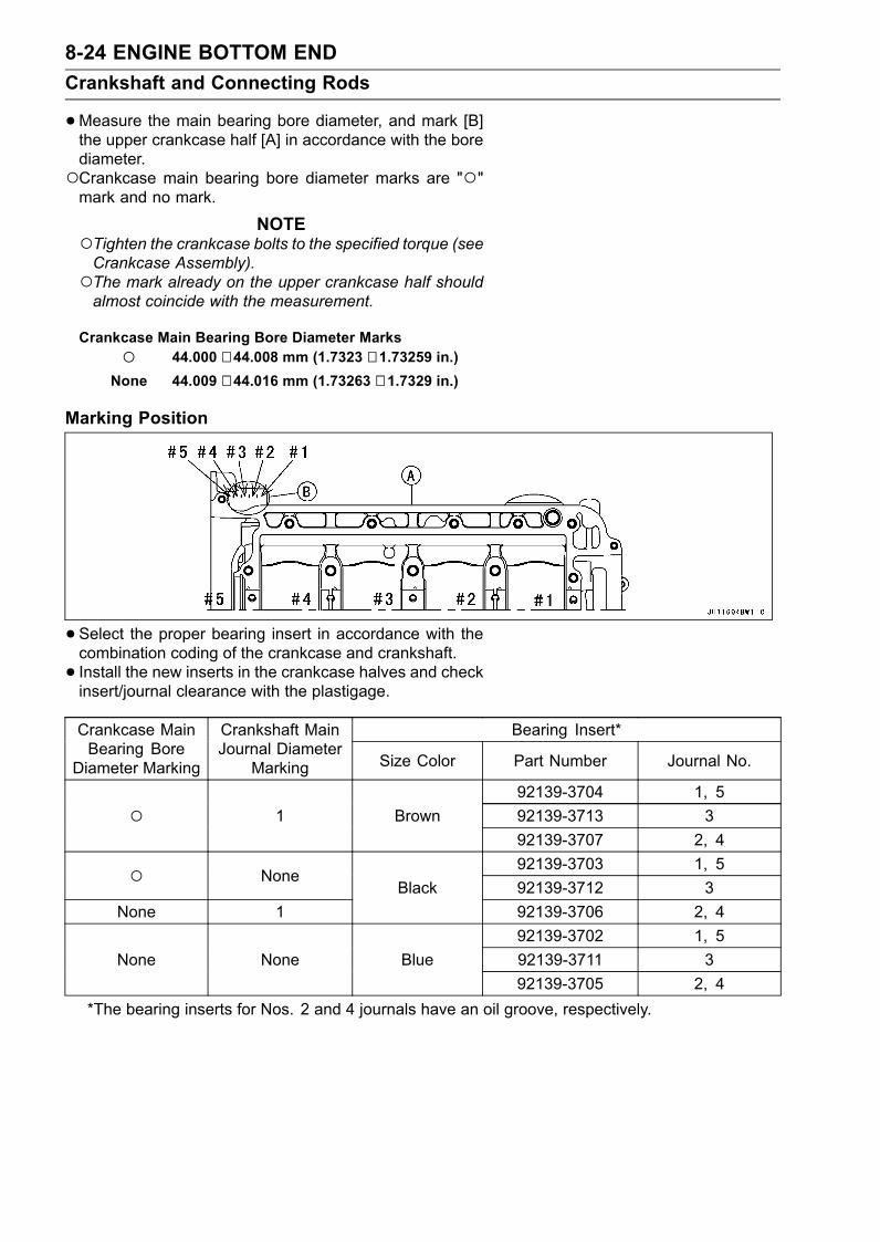
8-24 ENGINE BOTTOM ENDCrankshaft and Connecting Rods
•Measure the main bearing bore diameter, and mark [B]the upper crankcase half [A] in accordance with the borediameter.Crankcase main bearing bore diameter marks are ""mark and no mark.
NOTETighten the crankcase bolts to the specified torque (seeCrankcase Assembly).The mark already on the upper crankcase half shouldalmost coincide with the measurement.
Crankcase Main Bearing Bore Diameter Marks 44.000 ∼ 44.008 mm (1.7323 ∼ 1.73259 in.)None 44.009 ∼ 44.016 mm (1.73263 ∼ 1.7329 in.)
Marking Position
•Select the proper bearing insert in accordance with thecombination coding of the crankcase and crankshaft.• Install the new inserts in the crankcase halves and checkinsert/journal clearance with the plastigage.
Bearing Insert*Crankcase MainBearing Bore
Diameter Marking
Crankshaft MainJournal Diameter
Marking Size Color Part Number Journal No.
92139-3704 1, 592139-3713 3 1 Brown92139-3707 2, 492139-3703 1, 5 None92139-3712 3
None 1Black
92139-3706 2, 492139-3702 1, 592139-3711 3None None Blue92139-3705 2, 4
*The bearing inserts for Nos. 2 and 4 journals have an oil groove, respectively.

ENGINE BOTTOM END 8-25Crankshaft and Connecting Rods
Crankshaft Side Clearance• Insert a thickness gauge [A] between the thrust washer[B] and the crank web [C] at the No. 3 main journal todetermine clearance.If the clearance exceeds the service limit, replace thethrust washer as a set and check the width of the crank-shaft #3 main journal.
Crankshaft Side ClearanceStandard: 0.05 ∼ 0.24 mm (0.0020 ∼ 0.0094 in.)Service Limit: 0.44 mm (0.017 in.)
•Measure the crankshaft #3 main journal width [A].If the measurement exceeds the standard, replace thecrankshaft [B].
Crankshaft #3 Main Journal WidthStandard: 27.45 ∼ 27.55 mm (1.0807 ∼ 1.0846 in.)
Crankshaft Runout•Measure the crankshaft runout.If the measurement exceeds the service limit, replace thecrankshaft.
Crankshaft RunoutStandard: TIR 0.03 mm (0.0012 in.) or lessService Limit: TIR 0.07 mm (0.0028 in.)


COOLING AND BILGE SYSTEMS 9-1
9
Cooling and Bilge SystemsTable of Contents
Exploded View........................................................................................................................ 9-2Bilge System........................................................................................................................... 9-4
Breather Removal ............................................................................................................. 9-4Breather Installation .......................................................................................................... 9-4Breather Cleaning and Inspection..................................................................................... 9-4Filter Removal................................................................................................................... 9-4Filter Installation................................................................................................................ 9-5Filter Cleaning and Inspection .......................................................................................... 9-5
Cooling and Bilge System Hoses ........................................................................................... 9-6Hose Removal .................................................................................................................. 9-6Hose Installation ............................................................................................................... 9-6Hose Inspection ................................................................................................................ 9-6
Cooling and Bilge System Flushing........................................................................................ 9-7Cooling System Flushing .................................................................................................. 9-7Bilge System Flushing ...................................................................................................... 9-7
Cooling and Bilge System Flow Diagram ............................................................................... 9-8Water Pipe.............................................................................................................................. 9-9
Water Pipe Removal ......................................................................................................... 9-9Water Pipe Installation ...................................................................................................... 9-9
After Submerging.................................................................................................................... 9-10Summary Procedures after Submerging........................................................................... 9-10Detailed Procedures after Submerging............................................................................. 9-12

9-2 COOLING AND BILGE SYSTEMSExploded View

COOLING AND BILGE SYSTEMS 9-3Exploded View
TorqueNo. Fastener
N·m kgf·m ft·lbRemarks
1 Water Hose Joint (L Shape Type) 11 1.1 95 in·lb SS2 Water Hose Joint (Straight Shape Type) 20 2.0 14 SS3 Water Hose Joint (Straight Shape Type) 11 1.1 95 in·lb SS4 Cooling Hose Clamp Screws 2.5 0.25 22 in·lb5. Cylinder Head6. Water Pipe7. Cylinder Head Gasket8. Cylinder9. Oil Cooler10. Output Cover11. Exhaust Pipe12. Exhaust Pipe Gasket13. Exhaust Manifold14. Exhaust Manifold Gasket15. Bypass Outlet Nozzle16. Plastic Clamp17. Flushing Fitting18. Flushing Cap19. Detent20. Bypass Outlet21. Left Water Box Muffler22. Right Water Box Muffler23. Tail Pipe24. Cooling Water Filter Cover25. Cooling Water Filter26. Pump27. Bilge Breather28. Bilge Filter29. Pump Outlet30. Protective Tube31. Meter ClampCY: Apply cyanoacrylate cement.G: Apply grease.HG: Apply high-grade water-resistance grease (Chevron: Black Pearl Grease EP NLG12 or equiv-
alent).L: Apply a non-permanent locking agent.

9-4 COOLING AND BILGE SYSTEMSBilge System
Breather Removal•Remove:Seat (see Hull/Engine Hood chapter)Rear Storage Pocket• Pull the hoses [A] off the breather.• Unscrew the mounting bolts [B], and remove thebreathers [C].
Breather Installation•Be sure the small hole [A] in the breather is open beforeinstalling it.• Apply a non-permanent locking agent to the breathermounting bolts and tighten them.
Breather Cleaning and Inspection•Check that the small hole in the top of the breather is openby blowing in one end of the breather and plugging theother.If the hole is plugged, clean it with compressed air. Donot open it with a pointed object (like a needle or a pieceof wire), because the hole may be enlarged. If the hole istoo large, the bilge system may not suck water out of thehull as it should.
Filter RemovalFollow the next procedures to remove the filter [A].• Remove the engine (see Engine Removal/Installationchapter).• Pull the hose [B] off the filter.• Unscrew the mounting screw [C] and remove the filter.

COOLING AND BILGE SYSTEMS 9-5Bilge System
Filter Installation•Align the projections [A] on the filters [B] with the holes[C] on the brackets [D].
Filter Cleaning and Inspection•Flush the filter thoroughly with fresh water and shake itdry.•Water must flow freely through the filter, but large debrismust not.If the filter cannot be cleaned, or if it is broken and allowsdebris to pass through, replace it.

9-6 COOLING AND BILGE SYSTEMSCooling and Bilge System Hoses
Hose Removal•The majority of bilge hoses have no clamps at the hoseends. The majority of bilge system hoses may be simplypulled off their fittings.
NOTESome of the bilge system hoses have plastic clamps athose ends.
•All the cooling system hoses are clamped at both ends.Loosen the clamps and pull the hoses off.
Hose Installation•To install the bilge filter hose, push the hose over the endof the filter.
NOTESome of the bilge system hoses have plastic clamps athose ends.
•When installing the cooling system hoses, be sure touse the same kind of clamp as the original. Some of theclamps are metal for tighter clamping ability (requiredwhen smooth fittings are used). Plastic clamps are usedwhere tight clamping is not required.
Hose Inspection•Refer to Hose and Hose Connect Inspection in the Peri-odic Maintenance chapter.

COOLING AND BILGE SYSTEMS 9-7Cooling and Bilge System Flushing
Cooling System Flushing•Refer to Cooling System Flushing in the Periodic Mainte-nance chapter.
Bilge System Flushing•Refer to Bilge System Flushing in the Periodic Mainte-nance chapter.

9-8 COOLING AND BILGE SYSTEMSCooling and Bilge System Flow Diagram

COOLING AND BILGE SYSTEMS 9-9Water Pipe
Water Pipe Removal•Remove the inlet manifold (see Fuel System).• Disconnect the cooling hose [A] onto the water pipe fitting.• Unscrew the mounting bolts [B] and remove the waterpipe [C] from the cylinder head [D].
Water Pipe Installation•Apply grease to the O-rings [A] and install the water pipewith the mounting bolts.• Install cooling hose [B] (cylinder head ∼ water box muffler)to the water pipe fitting and secure the hose clamp [C].
9-10 COOLING AND BILGE SYSTEMSAfter Submerging
CAUTIONDo not operate the watercraft with water in the en-gine.Do not try to start the engine until it is completelyempty of water; internal engine parts could be se-verely and immediately damaged. If water gets intothe engine, follow this procedure immediately! Ifwater is left in the engine more than a few hours,it will destroy the crankshaft bearings and damageother internal engine parts.
If the watercraft becomes swamped, water may enter theengine through the throttle body. Water may also enter thefuel tank.The following procedures explain the necessary steps
you must provide.Read the summary of the procedure first and then their
detailed procedures carefully.
Summary Procedures after Submerging

COOLING AND BILGE SYSTEMS 9-11After Submerging

9-12 COOLING AND BILGE SYSTEMSAfter Submerging
Detailed Procedures after Submerging1. Remove the seat (see Hull/Engine Hood chapter).2. Remove the drain screws in the stern to drain waterout of the engine compartment.
3. Remove the front storage pocket (see Hull/EngineHood chapter).
4. Disconnect both two connectors [A] on the primaryignition leads located near the ignition coil.
5. Pull and remove all the spark plug caps.6. Remove all spark plugs. (see Spark Plug Cleaningand Inspection in Periodic Maintenance chapter)
7. Turn the ignition switch on, push the lanyard key un-der the stop button, and push the start button.
8. If there is any water in the engine, it will be pumpedout of the spark plug holes [A]. Do not operate thestarter for longer than 5 seconds. Wait 15 secondsbefore using it again. Be sure that all the water is outof the engine.
WARNINGDo not lean over the engine when performing thisprocedure. A water and gasoline mixture will beforcibly ejected from the spark plug holes and couldget into your eyes. If you do get some in your eyes,wash your eyes immediately with liberal amounts ofclean, fresh water. Consult a physician as soon aspossible.
9. Remove the rear storage pocket, and check the airfilter [A] for water inside with its drain caps [B].
10. If you see water in the caps, remove both caps anddischarge the water. Be sure to have a rag or clothunderneath for possible oily water. And proceed tothe next procedure (No.11).
NOTEIf you see water in the caps, there is a great possibilitythat water has entered the inlet manifold. If there is nowater in the caps, then proceed to No.12.
11. Remove the drain plug [A] of the inlet manifold [B] anddischarge water, if any, into a rag or cloth. (If you donot see water in the caps for the air filter mentionedabove, omit this procedure and proceed to the nextprocedure, No.12).
12. Spray the spark plugs clean and install them with theirplug caps.

COOLING AND BILGE SYSTEMS 9-13After Submerging
13. Reconnect the primary ignition coil lead connectors,noting the #1,#4 [A] and the #2, #3 [B] coil connec-tors. The #1, #4 coil connector has a red/yellow anda green/blue leads from the main harness. The #2,#3 coil connector has a red/yellow and green/blackleads from the main harness.
NOTEThe service codes (COIL1 and COIL2) caused by thisprocedure are stored in the ECU. If necessary, theseservice codes can be erased by using the KawasakiDiagnostic System (KDS).
14. Start the engine by pressing the start button and runless than 15 seconds.
CAUTIONDo not run the engine with the watercraft out of thewater for more than 15 seconds at a time. Overheat-ing will cause severe engine and exhaust systemdamage.Never operate the engine at maximum speed out ofthe water. Severe engine damage may occur.
15. Remove the dipstick [A] and check for the water pres-ence in the engine oil. (If there is water in it, oil looksmilky.)
16. If the oil looks milky, then change the oil and repeatprocedures 14 and 15 until the oil does not turn milkyany more.
17. If the engine does not start, there may be water in thefuel system.

9-14 COOLING AND BILGE SYSTEMSAfter Submerging
18. If the fuel tank has water in it, it must be emptied bypump or siphon. Refill the tank with fresh fuel. Do notdump contaminated fuel in places not designated forthat purpose.
WARNINGGasoline is extremely flammable and can be explo-sive under certain conditions. Pull the lanyard keyoff the stop button. Do not smoke. Make sure thearea is well ventilated and free from any source offlame or sparks; this includes any appliance with apilot light.
WARNINGGasoline is toxic substance. Dispose of gasolineproperly. Contact your local authorities for ap-proved disposal methods.
19. Continued troublemay require cleaning of the fuel lineto drain water.
20. Try to start the engine (procedure No.14) and proceedto the procedures No.15 and 16.
21. Reinstall the seat and secure it.22. Reinstall the drain screws in the stern.23. Finally, run the watercraft IN WATER for at least 10
minutes to dry any remaining water and blow any for-eign matter (like salt) out through the exhaust.

DRIVE SYSTEM 10-1
10
Drive SystemTable of Contents
Exploded View........................................................................................................................ 10-2Specification ........................................................................................................................... 10-4Special Tools and Sealant ...................................................................................................... 10-5Drive Shaft/Drive Shaft Holder ............................................................................................... 10-6
Drive Shaft Removal/Installation....................................................................................... 10-6Drive Shaft Holder Removal/Disassembly ........................................................................ 10-6Drive Shaft Holder Assembly/Installation.......................................................................... 10-7Drive Shaft Runout............................................................................................................ 10-8

10-2 DRIVE SYSTEMExploded View
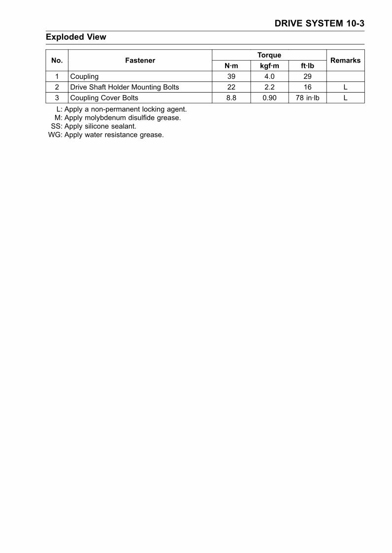
DRIVE SYSTEM 10-3Exploded View
TorqueNo. Fastener
N·m kgf·m ft·lbRemarks
1 Coupling 39 4.0 292 Drive Shaft Holder Mounting Bolts 22 2.2 16 L3 Coupling Cover Bolts 8.8 0.90 78 in·lb LL: Apply a non-permanent locking agent.M: Apply molybdenum disulfide grease.SS: Apply silicone sealant.WG: Apply water resistance grease.
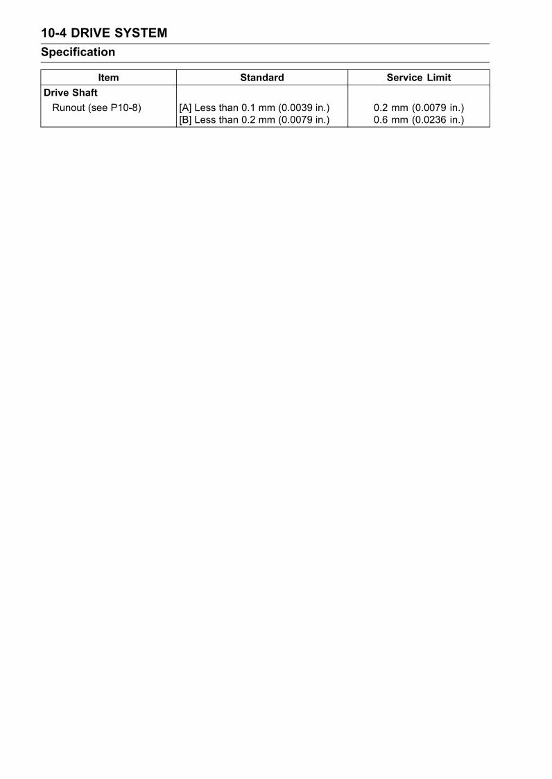
10-4 DRIVE SYSTEMSpecification
Item Standard Service LimitDrive ShaftRunout (see P10-8) [A] Less than 0.1 mm (0.0039 in.)
[B] Less than 0.2 mm (0.0079 in.)0.2 mm (0.0079 in.)0.6 mm (0.0236 in.)

DRIVE SYSTEM 10-5Special Tools and Sealant
Bearing Driver Set:57001-1129
Coupling Holder #2:57001-1423
Kawasaki Bond (Silicone Sealant):56019-120

10-6 DRIVE SYSTEMDrive Shaft/Drive Shaft Holder
Drive Shaft Removal/Installation•Remove the engine (see Engine Removal/Installationchapter).• Pull the drive shaft [A] out of the hull.
• Hold the drive shaft in a vice, and unscrew the coupling.Special Tool - Coupling Holder: 57001-1423 [A]
•When installing the drive shaft, be careful of the followingitems.Apply a non-permanent locking agent to the couplingthreads and tighten it.Torque - Coupling: 39 N·m (4.0 kgf·m, 29 ft·lb)Apply grease to the grease seal lips and the drive shaftspline.
Drive Shaft Holder Removal/Disassembly•Remove the drive shaft.• Unscrew the mounting bolts [A] and remove the driveshaft holder [B] from the bulkhead.
• Disassemble the drive shaft holder.Remove the circlip [A].

DRIVE SYSTEM 10-7Drive Shaft/Drive Shaft Holder
Press the small grease seal, and the large grease seals,bearing, and small grease seals come out of the holder.[A] Sleeve[B] Blocks[C] Press
Drive Shaft Holder Assembly/Installation•Replace the grease seals with new ones.• Press the bearing and grease seals into the drive shaftholder, noting the following.Install the parts in this order.Two Small Grease Seals [A]One Bearing [B]Two Large Grease Seals [C]Front [D]Special Tool - Bearing Driver Set: 57001-1129Install the seals so that the sides with the spring face out-ward.Fill the gaps between the seals with water resistancegrease [E].• Install the circlip.• Apply water resistance grease to the bearing inner sur-face and grease seal lips.
• Install the drive shaft holder on the bulkhead so that thecirclip side face toward the front.• Apply a non-permanent locking agent to the drive shaftholder mounting bolts, tighten them loosely.• Install the drive shaft.• After installing the engine, tighten the drive shaft holdermounting bolts to the specified torque to give proper cou-pling alignment.Torque - Drive Shaft Holder Mounting Bolts: 22 N·m (2.2
kgf·m, 16 ft·lb)
•Make sure the clearance [A] between the engine coupling[B] and the drive shaft coupling [C] is 3 ∼ 5 mm (0.12 ∼0.20 in.).

10-8 DRIVE SYSTEMDrive Shaft/Drive Shaft Holder
Drive Shaft Runout•Measure drive shaft runout by supporting the shaft on Vblocks and setting a dial gauge against the shaft at eachpoint shown.• Turn the drive shaft slowly. The difference between thehighest and lowest dial gauge reading is the runout.If any measurement exceeds the service limit, replace theshaft.
Drive Shaft RunoutStandard: Less than 0.1 mm (0.0039 in.) [A]
Less than 0.2 mm (0.0079 in.) [B]Service Limit: 0.2 mm (0.0079 in.) [A]
0.6 mm (0.0236 in.) [B]
PUMP AND IMPELLER 11-1
11
Pump and ImpellerTable of Contents
Exploded View........................................................................................................................ 11-2Specifications ......................................................................................................................... 11-4Special Tools and Sealant ...................................................................................................... 11-5Pump and Impeller ................................................................................................................. 11-6
Pump Removal ................................................................................................................. 11-6Pump Installation .............................................................................................................. 11-7Pump Disassembly ........................................................................................................... 11-8Pump Assembly ................................................................................................................ 11-10Impeller Inspection............................................................................................................ 11-12Impeller Outside Diameter Measurement ......................................................................... 11-13Pump Inspection ............................................................................................................... 11-13Impeller Clearance............................................................................................................ 11-13Water Filter Cover Removal/Installation ........................................................................... 11-13
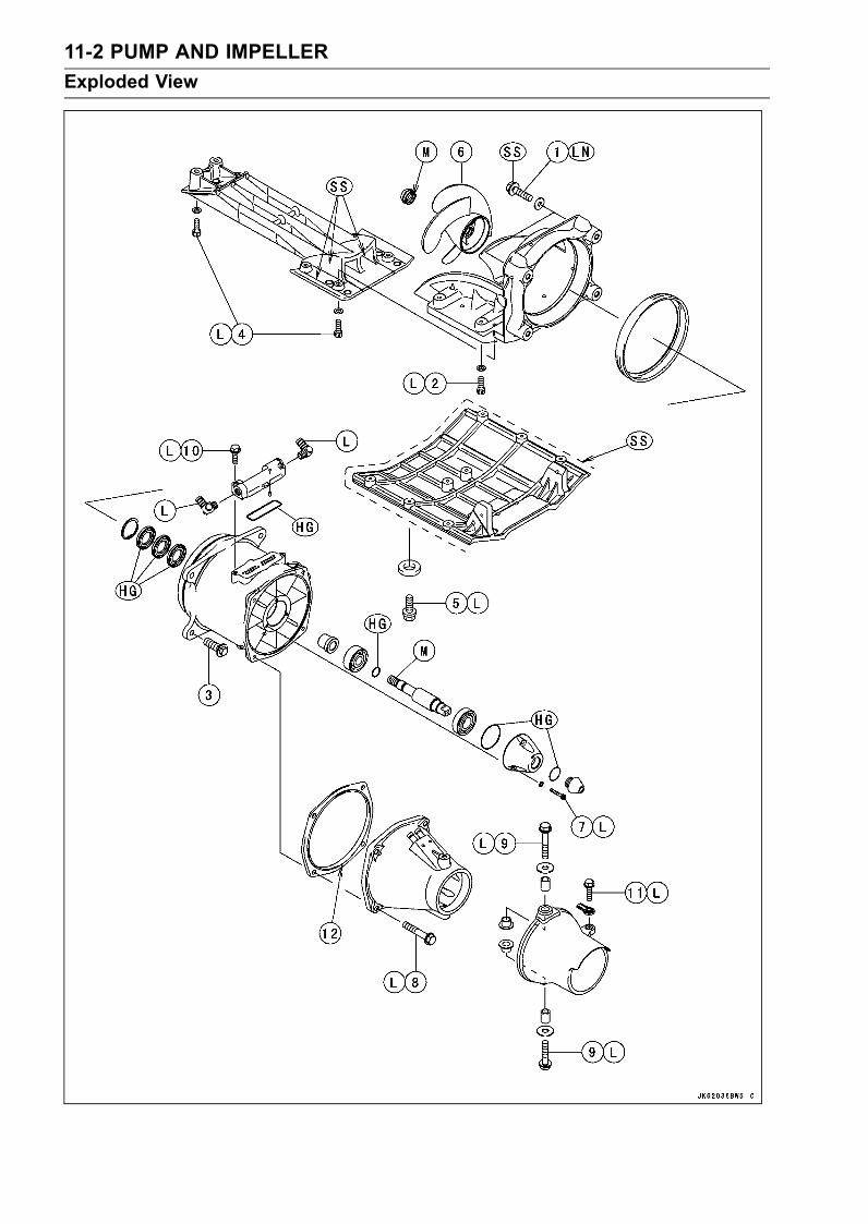
11-2 PUMP AND IMPELLERExploded View

PUMP AND IMPELLER 11-3Exploded View
TorqueNo. Fastener
N·m kgf·m ft·lbRemarks
1 Pump Bracket Mounting Bolts (2) 19 1.9 14 LN, SS2 Pump Bracket Mounting Bolts (4) 9.8 1.0 87 in·lb L3 Pump Mounting Bolts 36 3.7 27 L4 Grate Mounting Bolts 9.8 1.0 87 in·lb L5 Pump Cover Mounting Bolts 7.8 0.80 69 in·lb L6 Impeller 98 10 727 Pump Cap Bolts 3.9 0.4 35 in·lb L8 Pump Outlet Mounting Bolts 19 1.9 14 L9 Steering Nozzle Pivot Bolts 19 1.9 14 L10 Filter Cover Mounting Bolts 9.8 1.0 87 in·lb L11 Steering Cable Joint Bolt 9.8 1.0 87 in·lb L12. Install the spacer so that its mark "JT1500C DOWN" (Thicker Side) faces downwards.HG: Apply high grade water resistance grease (Chevron: Black Pearl Grease EP NLGI 2 or equiva-
lent).L: Apply a non-permanent locking agent.LN: Apply a non-permanent locking agent (High Strength: Loctite 271 equivalent).M: Apply molybdenum disulfide grease.SS: Apply silicone sealant.

11-4 PUMP AND IMPELLERSpecifications
Item Standard Service LimitJet PumpImpeller Outside Diameter 154.5 ∼ 154.7 mm (6.0827 ∼ 6.0905 in.) 153.5 mm (6.0433 in.)Pump Case Inside Diameter 155.0 ∼ 155.1 mm (6.1024 ∼ 6.1063 in.) 156.1 mm (6.1457 in.)Impeller Clearance 0.15 ∼ 0.3 mm (0.0059 ∼ 0.0118 in.) 0.6 mm (0.0236 in.)
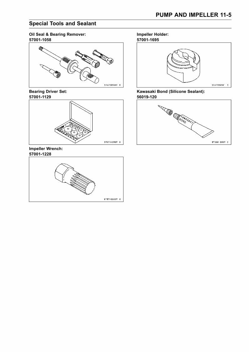
PUMP AND IMPELLER 11-5Special Tools and Sealant
Oil Seal & Bearing Remover:57001-1058
Bearing Driver Set:57001-1129
Impeller Wrench:57001-1228
Impeller Holder:57001-1695
Kawasaki Bond (Silicone Sealant):56019-120

11-6 PUMP AND IMPELLERPump and Impeller
Pump Removal•Turn the craft on its left side.• Disconnect the reverse cable ball joint at the rear end.• Unscrew the pump cover mounting bolts [A], and removethe pump cover [B] with the reverse bracket [C].• Unscrew the grate mounting bolts [D] and remove thegrate [E].
NOTECut the sealant at the indicated area [F] in the figure.
•Remove the joint bolts [A] and take off the steering cablejoint.• Loosen the clamps [B] on the inlet cooling hose, and pulloff the hoses [C].
• Unscrew the pump mounting bolts [A].• Slide the pump [B] to the rear to disengage the drive shaft,and remove it from the hull.
• To remove the pump bracket, perform the following pro-cedures.Take out the pump bracket mounting bolts [A] and washerin the hull.
Take out the pump bracket mounting bolts [A].

PUMP AND IMPELLER 11-7Pump and Impeller
Cut the sealant at the indicated area [A] in the figure andremove the pump bracket [B].
Pump Installation•Strip off all the old sealant around the pump intake.• Liberally coat the outside edge of the pump bracket withsilicon sealant [A] to form a seal between the bracket andthe hull.Sealant - Kawasaki Bond (Silicone Sealant): 56019-120
• Install the pump bracket [A] to the hull.Apply a non-permanent locking agent (High Strength:Loctite 271 equivalent) to the pump bracket mountingbolts (2) and torque them.Torque - Pump Bracket Mounting Bolts (2) [B]: 19 N·m (1.9
kgf·m, 14 ft·lb)Apply a non-permanent locking agent to the pump bracketmounting bolts (4) and torque them.Torque - Pump Bracket Mounting Bolts (4) [C]: 9.8 N·m (1.0
kgf·m, 87 in·lb)As for the pump bracket mounting bolts (2) in the hull, thebolt heads should be wrapped in silicone sealant.
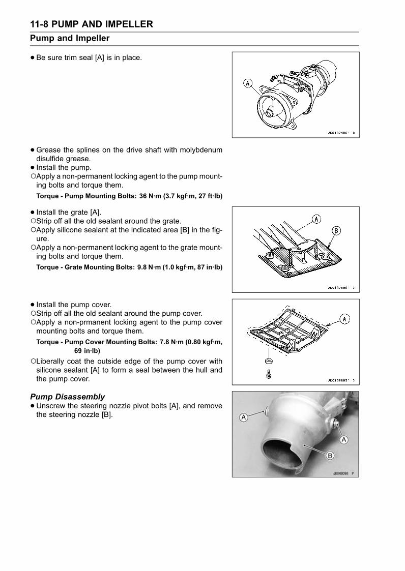
11-8 PUMP AND IMPELLERPump and Impeller
•Be sure trim seal [A] is in place.
•Grease the splines on the drive shaft with molybdenumdisulfide grease.• Install the pump.Apply a non-permanent locking agent to the pump mount-ing bolts and torque them.Torque - Pump Mounting Bolts: 36 N·m (3.7 kgf·m, 27 ft·lb)
• Install the grate [A].Strip off all the old sealant around the grate.Apply silicone sealant at the indicated area [B] in the fig-ure.Apply a non-permanent locking agent to the grate mount-ing bolts and torque them.Torque - Grate Mounting Bolts: 9.8 N·m (1.0 kgf·m, 87 in·lb)
• Install the pump cover.Strip off all the old sealant around the pump cover.Apply a non-prmanent locking agent to the pump covermounting bolts and torque them.Torque - Pump Cover Mounting Bolts: 7.8 N·m (0.80 kgf·m,
69 in·lb)Liberally coat the outside edge of the pump cover withsilicone sealant [A] to form a seal between the hull andthe pump cover.
Pump Disassembly•Unscrew the steering nozzle pivot bolts [A], and removethe steering nozzle [B].

PUMP AND IMPELLER 11-9Pump and Impeller
•Unscrew the pump outlet mounting bolts [A], and removethe pump outlet [B].
• Unscrew the pump cap bolts [A], and remove the pumpcap [B].
• Pull out the impeller seal on the impeller.• Hold the shaft in the impeller holder, taking care not todamage it. Remove the impeller from the pump shaft andthen pull out the pump shaft.Special Tools - Impeller Holder: 57001-1695 [A]
Impeller Wrench: 57001-1228 [B]
•Pull the pump shaft [A] with the bearing [B] out of thepump case.

11-10 PUMP AND IMPELLERPump and Impeller
•Remove the bearing [C] from the pump shaft [B] with apress [A].
• Press [A] the bussing [B] and the ball bearing [C]. Theycome out of the pump case.
• Remove the circlip.• Remove the grease seals.Special Tool - Oil Seal & Bearing Remover: 57001-1058 [A]
Pump Assembly•Before installing the pump bearing, blow any dirt or for-eign particles out of the pump case with compressed air.• Before installing the pump bearing, remove the filter cover[C], and check the filter inside or outside [A] on the pumpcase [B] if the foreign particles do not cling to the filter.Apply high grade water resistant grease to the O-ring [D].Apply a non-permanent locking agent to the filter covermounting bolts and torque them.Torque - Filter Cover Mounting Bolts: 9.8 N·m (1.0 kgf·m,
87 in·lb)

PUMP AND IMPELLER 11-11Pump and Impeller
•Replace the grease seals with new ones, if necessary,and install them.Special Tool - Bearing Driver Set: 57001-1129Press each seal [A] into the pump case [B] so that the sidewith the spring faces outward.Fill the gap between the grease seals [A] with high gradewater resistance grease and apply it each grease seal lip[C].• Install the circlip [D].• Install the bushing [E] into the pump case.Fill with high grade water resistance grease (4g) [F].
• Install a new bearing into the pump case [A] as far as itwill go.Special Tool - Bearing Driver Set: 57001-1129 [B]
•Visually inspect the pump shaft O-rings [A], and replaceif necessary.• Install the O-ring over the pump shaft [B].Grease the O-ring with high grade water resistancegrease.• Press the pump shaft into the bearing as far as it will go.
• Apply molybdenum disulfide grease [A] to the thread ofthe pump shaft• Push the pump shaft [B] into the pump case.

11-12 PUMP AND IMPELLERPump and Impeller
•Screw on the impeller and torque.Special Tools - Impeller Holder: 57001-1695
Impeller Wrench: 57001-1228
Torque - Impeller: 98 N·m (10 kgf·m, 72 ft·lb)
•Visually inspect impeller seal [A], and replace it if neces-sary.• Install the seal on the impeller.
• Be sure the O-rings [A] are in place on the pump cap [B]and plug [C].Apply high grade water resistance grease to the O-rings.
• Install the following.Pump CapPump Cap PlugSpacerPump OutletSteering Nozzle
Install the spacer [A] so that its mark "JT1500C DOWN"(Thicker Side) [B] faces downwards.Apply a non-permanent locking agent to the thread of thefollowing.Pump Cap BoltsPump Outlet Mounting BoltsSteering Nozzle Pivot BoltsTorque - Pump Cap Bolts: 3.9 N·m (0.40 kgf·m, 35 in·lb)
Pump Outlet Mounting Bolts: 19 N·m (1.9 kgf·m,14 ft·lb)
Steering Nozzle Pivot Bolts: 19 N·m (1.9 kgf·m, 14ft·lb)
•Be sure the pump seal [A] is in place on the pump case.
Impeller Inspection•Refer to Impeller Inspection in the Periodic Maintenancechapter.

PUMP AND IMPELLER 11-13Pump and Impeller
Impeller Outside Diameter Measurement•Measure the impeller outside diameter.If the impeller is worn smaller than the service limit, re-place it.
Impeller Outside DiameterStandard: 154.5 ∼ 154.7 mm (6.0827 ∼ 6.0905 in.)Service Limit: 153.5 mm (6.0433 in.)
Pump Inspection•Examine the pump case [A].If there are deep scratches inside the pump case, replaceit.
Measure the inside diameter of the pump case.If the pump case is worn beyond the service limit, replaceit.
Pump Case Inside Diameter
Standard: 155.0 ∼ 155.1 mm (6.1024 ∼ 6.1063 n.)
Service Limit: 156.1 mm (6.1457 in.)
Impeller Clearance• Impeller clearance is critical to proper performance. If thepump case and impeller are not visibly damaged, poorperformance may be caused by too much impeller clear-ance.• To check impeller clearance, remove the grate and inserta feeler gauge [A] between the tip of the impeller blade[B] and the pump case [C].
Impeller ClearanceStandard: 0.15 ∼ 0.3 mm (0.0059 ∼ 0.0118 in.)Service Limit: 0.6 mm (0.0236 in.)
If impeller clearance is incorrect, determine if it is due towear or damage (see Pump and Impeller Inspection).
Water Filter Cover Removal/Installation• Loosen the clamps [A] and pull off the hoses [B].• Remove the filter cover mounting bolts [C].• Take out the filter cover [D].• Replace the gasket with a new one.• Installation is the reverse order of removal.• Apply a non-permanent locking agent to the filter covermounting bolts and torque them.Torque - Filter Cover Mounting Bolts: 9.8 N·m (1.0 kgf·m,
87 in·lb)


STEERING 12-1
12
SteeringTable of Contents
Exploded View........................................................................................................................ 12-2Special Tools .......................................................................................................................... 12-4Steering Cable........................................................................................................................ 12-5
Steering Cable Adjustment ............................................................................................... 12-5Steering Cable Removal ................................................................................................... 12-5Steering Cable Installation ................................................................................................ 12-7Steering Cable Inspection................................................................................................. 12-7Steering Cable Lubrication................................................................................................ 12-7
Handlebar ............................................................................................................................... 12-8Handlebar Removal .......................................................................................................... 12-8Handlebar Installation ...................................................................................................... 12-8
Steering .................................................................................................................................. 12-10Steering Removal ............................................................................................................. 12-10Steering Installation ......................................................................................................... 12-13Adjustable Steering Holder Disassembly.......................................................................... 12-16Adjustable Steering Holder Assembly............................................................................... 12-16
Reverse System ..................................................................................................................... 12-18Shift Cable Adjustment ..................................................................................................... 12-18Shift Cable Removal ......................................................................................................... 12-18Shift Cable Installation ..................................................................................................... 12-20Shift Cable Inspection ....................................................................................................... 12-20Shift Cable Lubrication...................................................................................................... 12-20Reverse Bucket Removal/Installation ............................................................................... 12-20Shift Lever Shaft Removal/Installation .............................................................................. 12-20

12-2 STEERINGExploded View

STEERING 12-3Exploded View
TorqueNo. Fastener
N·m kgf·m ft·lbRemarks
1 Handlebar Clamp Bolts 16 1.6 12 L2 Adjustable Steering Holder Nut 20 2.0 14.53 Steering Neck Mounting Bolts 16 1.6 12 L4 Steering Shaft Locknut 49 ∼ 59 5.0 ∼ 6.0 36 ∼ 435 Steering Holder Mounting Nuts 20 2.0 14.5 L6 Throttle Case Mounting Screws 3.9 0.40 35 in·lb7 Start/stop Switch Case Mounting Screws 3.9 0.40 35 in·lb8 Shift Cable Nut 39 4.0 299 Steering Cable Nut 39 4.0 2910 Steering Shaft Nut 2.9 0.30 26 in·lb see text11 Steering Cable Joint Bolt 9.8 1.0 87 in·lb L12 Ball Joint 9.8 1.0 87 in·lb L13 Shift Cable End Nut 9.8 1.0 87 in·lb14 Reverse Bucket Pivot Bolts 19 1.9 14 L15. Buzzer16. Steering Position Sensor17. Magnet18. Red Mark19. White Mark20. Red MarkA: JT1500C8FB: JT1500C7FG: Apply grease.L: Apply a non-permanent locking agent.LN: Apply a non-permanent locking agent (High Strength: Loctite 271 equivalent).

12-4 STEERINGSpecial Tools
Box Wrench (27 mm):57001-1451
Nut Tightening Plate:57001-1698

STEERING 12-5Steering Cable
Steering Cable Adjustment•Check the steering cable adjustment.Center the handlebar in the straight-ahead position.
• Check that the steering nozzle [A] is centered in the pumpcavity.The same distance [B].
• If necessary, adjust the steering cable.Loosen the locknut [A] on the end of the steering cablelocated to the right of the steering nozzle.Take out the cable joint bolt [B] and disconnect the cablejoint [C] from the steering nozzle.Center the handlebar in a straight ahead steering position.Turn the joint on the cable to adjust the steering. Thesteering cable rod end must be inserted to the joint a min-imum of 5 mm (0.2 in.).Temporarily tighten the cable joint bolt, and connect thejoint with the nozzle and check cable adjustment again.When adjustment is correct, unscrew the cable joint boltand apply a non-permanent locking agent to it. Andtighten the cable joint bolt and the steering cable locknutsecurely.Torque - Cable Joint Bolt: 9.8 N·m (1.0 kgf·m, 87 in·lb)As an additional check, turn the handlebar all the way tothe left and right, and measure the distance between thenozzle and the edge of the pump cavity. It should be equalat both extremes.
Steering Cable Removal•Remove the steering cover (see Steering Removal).• Pull out the center access cover [A].

12-6 STEERINGSteering Cable
•Slide back the outer sleeve of the ball joint and take offthe ball joint.• Remove the cable bracket mounting bolts [A].
• Loosen the locknut [A] at the front end of the steeringcable and take off the ball joint [B], and remove the locknutfrom the cable front end.• Pull the holder [C] off the cable bracket [D].• Slide the steering cable [E] off the cable bracket.
• Turn the watercraft on its left side and remove the pumpcover (see Pump Removal in Pump/Impeller chapter).
CAUTIONNever lay the watercraft on the right side. Water inthe exhaust systemmay drain back into the engine,causing serious damage.
• Loosen the locknut [A] at the rear end of the steering ca-ble, and remove the joint bolt [B].• Remove the joint [C] and locknut from the cable end.• Unscrew the large nut (steering cable nut) in the hull witha wrench.Special tool, box wrench [A] is useful to remove the largenut (steering cable nut).Special Tool - Box Wrench: 57001-1451
•Slide off the snap ring [A], washer [B] and O-ring [C].• Pull out the steering cable toward the rear.

STEERING 12-7Steering Cable
Steering Cable Installation•Slide a short piece of rubber or plastic tubing over the frontcable end to guide the cable through the hull.• Lubricate the outside of the new cable to ease cable in-stallation.• Torque:Torque - Steering Cable Nut: 39 N·m (4.0 kgf·m, 29 ft·lb)
•Align the groove [A] on the steering cable with the openingportion [B] on the cable bracket as shown.• Install the steering cable both end to the joints. The steer-ing cable rod ends must be inserted to the joints a mini-mum of 5 mm (0.2 in.).• Apply a non-permanent locking agent to the cable jointbolt and the steering cable bracket mounting bolts.Torque - Cable Joint Bolt: 9.8 N·m (1.0 kgf·m, 87 in·lb)
•Apply a water resistant grease to the joint ball.• Adjust the steering cable (see Steering Cable Adjust-ment).
Steering Cable Inspection•Refer to Steering Cable/Shift Cable Inspection in the Pe-riodic Maintenance chapter (see Steering Cable/Shift Ca-ble Inspection in the Periodic Maintenance chapter).
Steering Cable LubricationNOTE
The steering cable is sealed at each end and do notrequire lubrication. If the seal is damaged, the cablemust be replaced.

12-8 STEERINGHandlebar
Handlebar Removal•Unscrew the mounting screws [A] and remove the han-dlebar pad [B].
• Remove the inner pad [A] and the buzzer [B].
• Unscrew the bolts [A] and remove the pad holder [B].
• Take out the throttle case clamp screws and remove thethrottle case [A].• Take out the switch case clamp screws and remove theswitch case [B].• Cut off the clamps [C] holding the switch leads and throttlecable.• Unscrew the handlebar clamp bolts [D] and remove thehandlebar clamps [E] and handlebar [F].
Handlebar Installation• Install the pad holder.Apply a non-permanent locking agent to the pad holderbolts.• Install the handlebar on the holder of the steering neck.Apply a non-permanent locking agent to the handlebarclamp bolts.
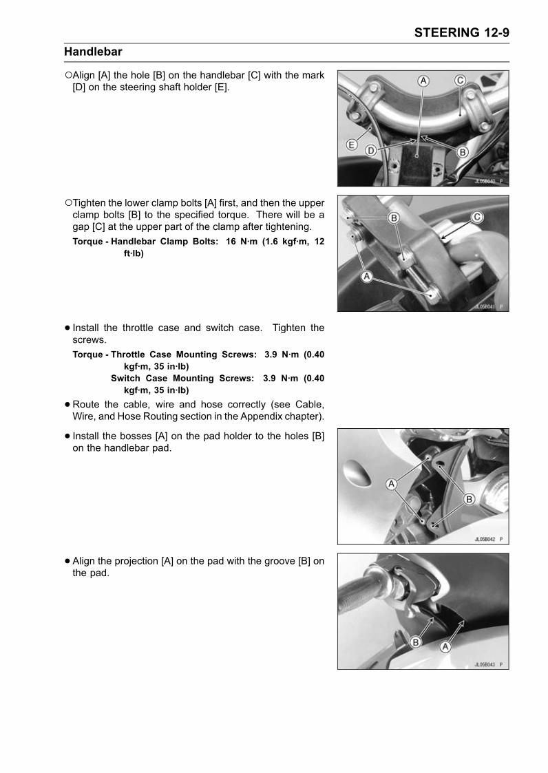
STEERING 12-9Handlebar
Align [A] the hole [B] on the handlebar [C] with the mark[D] on the steering shaft holder [E].
Tighten the lower clamp bolts [A] first, and then the upperclamp bolts [B] to the specified torque. There will be agap [C] at the upper part of the clamp after tightening.Torque - Handlebar Clamp Bolts: 16 N·m (1.6 kgf·m, 12
ft·lb)
• Install the throttle case and switch case. Tighten thescrews.Torque - Throttle Case Mounting Screws: 3.9 N·m (0.40
kgf·m, 35 in·lb)Switch Case Mounting Screws: 3.9 N·m (0.40kgf·m, 35 in·lb)
•Route the cable, wire and hose correctly (see Cable,Wire, and Hose Routing section in the Appendix chapter).
• Install the bosses [A] on the pad holder to the holes [B]on the handlebar pad.
• Align the projection [A] on the pad with the groove [B] onthe pad.

12-10 STEERINGSteering
Steering Removal•Remove the center storage compartment lid (seeRight/Left Cover Removal in the Hull/Engine Hoodchapter).• Remove the right/left cover (see Right/Left Cover Re-moval in the Hull/Engine Hood chapter).• Remove the handlebar and pad holder (see HandlebarRemoval).• Disconnect the shif cable ball joint [A] at the upper end.• Unscrew the immobilizer switch mounting bolts [B] andwashers.
• Unscrew the meter mounting bolts [A].
• Unscrew the steering cover mounting nuts [A] and wash-ers and lift up the steering cover [B].
• Disconnect the fuel vent hose [A].• Unscrew the meter mounting bolts [B] and washers andremove the meter unit [C] with the leads.• Remove the steering cover [D].
• Take out the rivets [A] and remove the steering pad [B].

STEERING 12-11Steering
•Remove the cotter pin [A].• Unscrew the nut [B] and bolt [C], and take off the washers[D].
• Pull out the shaft [A], and remove the bushings [B] andadjustable steering holder [C].
• Unscrew the steering neck mounting bolts [A] and removethe steering neck.
• Remove:Cotter Pin [A]Steering Shaft Locknut [B]WasherHolder [C]
• Remove:Lock Plate Mounting Bolts [A]Lock Plate [B]Steering Shaft Nut [C]Steering Shaft [D]

12-12 STEERINGSteering
•Unscrew the grommet mounting plate bolts [A] and re-move the grommet mounting plate [B].• Pull up the grommet [C].
• Disconnect:Steering Position Sensor Lead ConnectorBuzzer ConnectorMultifunction Meter Lead ConnectorsSteering Cable Ball Joint at Upper EndSwitch Case Lead ConnectorThrottle Cable Upper End at Throttle Case
•Pull up:Multifunction Meter Leads [A]Buzzer Leads [B]Switch Case Leads [C]• Pull down:Fuel Vent Hose [D]Throttle Cable [E]
• Unscrew the steering holder mounting nuts [A], washers[B] and bracket [C], and take off the steering holder [D].• Remove the bushings [E].

STEERING 12-13Steering
Steering Installation•Replace the gasket [A] on the steering holder [B] with anew one.• Check the bushings for damage and wear before in-stalling the steering holder.If the bushings are damaged or worn, replace them.•Grease:Bushings [C]• Put the washer [D] on the steering holder.
•Grease:Steering Shaft [A]
• Install the steering shaft.• Tighten the steering shaft nut [A] by hand and then looseone time.

12-14 STEERINGSteering
•Put the nut tightening plate [A] on the steering shaft nut[B].• Install the tightening plate with two bolts [C].Special Tool - Nut Tightening Plate: 57001-1698
• Insert the square projection of the torque wrench to thesquare hole [D] of the plate.• Tighten the plate together with steering shaft nut.Torque - Steering Shaft Nut: 2.9 N·m (0.30 kgf·m, 26 in·lb)
•Remove the bolts and tightening plate (special tool).• Loosen the steering shaft nut so that threads [A] of steer-ing shaft nut are aligned with the holes [B] of plate [C]within second chance.• Tighten the bolts [D] and check steering shaft turns freelywith no play.
• Torque the steering shaft locknut [A].Torque - Steering Shaft Locknut: 49 ∼ 59 N·m (5.0 ∼ 6.0
kgf·m, 36 ∼ 44 ft·lb)

STEERING 12-15Steering
•Turning the steering shaft fully in left and right direction,check whether the steering position sensor comes in con-tact with the magnet.• Check the clearance [A] between the steering positionsensor [B] and the magnet [C] with feeler gauge.
Steering Position Sensor ClearanceStandard: 0.5 ∼ 1.5 mm (0.02 ∼ 0.06 in.)
If necessary, adjust the clearance by turning the steeringshaft nut.
• Replace the cotter pin [A] with a new one.NOTE
When inserting the cotter pin, if the slots in the locknutdo not align with the cotter pin hole in the steering shaft,tighten the locknut clockwise [B] up to next alignment.It should be within 30 degree.Loosen once and tighten again when the slot goes pastthe nearest hole.
•Bend the cotter pin over the nut.• Install the steering holder.Torque - Steering HolderMountingNuts: 20 N·m (2.0 kgf·m,
15 ft·lb)
• Install the steering neck [A] so that its wide side [B] facesthe front [D] as shown.Narrow Side [C]•Grease [E] the upper part of the steering neck and thelower part of the adjustable rod.• Apply a non-permanent locking agent to the steering neckmounting bolts.Torque - Steering Neck Mounting Bolts: 16 N·m (1.6 kgf·m,
12 ft·lb)
•Apply a non-permanent locking agent to the grommetmounting plate.Torque - Adjustable Steering Holder Nut [A]: 16 N·m (1.6
kgf·m, 12 ft·lb)
•Apply a water resistant grease to the joint balls of the shiftcable and shift link rod.• Adjust the steering cable.

12-16 STEERINGSteering
•Replace the cotter pin [A] with a new one.NOTE
When inserting the cotter pin, if the slots in the locknutdo not align with the cotter pin hole in the steering shaft,tighten the locknut clockwise [B] up to next alignment.It should be within 30 degree.Loosen once and tighten again when the slot goes pastthe nearest hole.
•Bend the cotter pin over the nut.Adjustable Steering Holder Disassembly•Remove the adjustable steering holder (see Steering Re-moval).• Remove the following from the adjustable steering holder[A].Rivets [B]Shaft [C]Tilt Lever [D]Springs [E]Rod [F]
Adjustable Steering Holder Assembly• Insert the rod [B] into the adjustable steering holder [A].Align [C] the projections on the rod with the grooves onthe holder.
• Be sure that the springs [A] are in place

STEERING 12-17Steering
• Install the tilt lever [A] on the adjustable steering holder.Align [B] the projection on the rod with the hole on the tiltlever.

12-18 STEERINGReverse System
Shift Cable Adjustment•Check the shift cable adjustment.•When the shift lever is in the “F” position, the lower edge[A] of the bucket should be held above the top [B] of thesteering nozzle with slight play so it doesn’t interfere withthe water flow from the jet pump.•When the shift lever is in the “R” position, the lower stop-per [C] on the bucket should rest against the bottom [D]of the pump cover.
If either position is incorrect, adjust the shift cable.• Put the shift lever in the “R” position.• Loosen the locknut [A] at the end of the shift cable.• Slide back the outer sleeve and take the ball joint [B] offthe ball.• Turn the ball joint on the cable to adjust the shift cable.• Connect the ball joint and check the cable adjustmentagain.•When adjustment is correct, tighten the shift cable lock-nut.
Shift Cable Removal• Lift up the steering cover [A] (see Steering Removal).
• Remove:Plate Bolts [A]Plate [B]

STEERING 12-19Reverse System
• Loosen the locknut [A] at the front end of the shift cableand take off the ball joint [B], and remove the locknut fromthe cable front end.• Pull the holder [C] off the cable bracket [D].• Remove the cable bracket mounting bolts [E].• Slide the shift cable [F] off the cable bracket.
• Turn the water craft on its left side and remove the pumpcover (see Pump Removal in the Pump/Impeller chapter).
CAUTIONNever lay the watercraft on the right side. Water inthe exhaust systemmay drain back into the engine,causing serious damage.
• Loosen the locknut [A] at the rear end of the shift cable,and remove the ball joint [B] from the reverse bucket [C],
• Disconnect the shift cable from the fitting at the middle ofthe hull.Unscrew the large nut (shift cable nut) in the hull with awrench.Special tool, box wrench [A] is useful to remove the largenut (shift cable nut).Special Tool - Box Wrench: 57001-1451
•Slide off the snap ring [A], washer [B] and O-ring [C].• Pull out the shift cable toward the rear.

12-20 STEERINGReverse System
Shift Cable Installation•Slide a short piece of rubber or plastic tubing over the frontcable end to guide the cable through the hull.• Lubricate the outside of the new cable to ease cable in-stallation.• Torque the shift cable nut.Torque - Shift Cable Nut: 39 N·m (4.0 kgf·m, 29 ft·lb)
•Align the groove [A] on the steering cable with the openingportion [B] on the cable bracket as shown.• Apply a non-permanent locking agent (High Strength:Loctite 271 equivalent) to the cable bracket mountingbolt.• Apply a water resistant grease to the joint ball at each endof shift cable.• Adjust the shift cable (see Shift Cable Adjustment).Shift Cable Inspection•Refer to Steering Cable/Shift Cable Inspection in the Pe-riodic Maintenance chapter (see Steering Cable/Shift Ca-ble Inspection in the Periodic Maintenance chapter).
Shift Cable LubricationNOTE
The shift cable is sealed at each end and do not requirelubrication. If the seal is damaged, the cable must bereplaced.
Reverse Bucket Removal/Installation•Disconnect the ball joint at rear end of the shift cable.• Remove the pump cover (see Pump Removal in thePump/Impeller chapter).• Unscrew the pivot bolts [A] and remove the reversebucket [B].• Installation is the reverse of removal. Note the following.Apply a non-permanent locking agent (High Strength:Loctite 271 equivalent) to the reverse bucket pivot bolts,and torque them.Torque - Reverse Bucket Pivot Bolts: 19 N·m (1.9 kgf·m, 14
ft·lb)After installation, check the shift cable adjustment.Shift Lever Shaft Removal/Installation•Remove the right/left cover (see Right/Left Cover Re-moval in the Hull/Engine Hood chapter).• Disconnect the shift cable ball joint [A] at upper end.• Unscrew the shift lever bolt [B] and remove the shift lever[C].

STEERING 12-21Reverse System
•Unscrew the steering cover bolts (see Steering Removal).• Remove:Shift Lever Holder Bolts [A]Washer (JT1500C8F) [B]Collars [C]Shift Lever Holder [D]Shift Lever Bracket [E]Shift Lever Shaft [F]
Lift up the steering cover [G] (see Steering Removal).
• Assemble the shift lever holder, noting the following.Apply a non permanent locking agent (Hight Strength:Loctite 271 equivalent) to the shift lever holder bolts.Align the slot [A] on the shift lever shaft with the projection[B] on the shift lever.Before connecting the shift cable, apply a water resistantgrease to its joint ball.
• Inspect the reverse lever [A] is properly locked [B] to for-ward.Adjust the position if necessary.


HULL/ENGINE HOOD 13-1
13
Hull/Engine HoodTable of Contents
Exploded View........................................................................................................................ 13-2Fittings .................................................................................................................................... 13-6
Seat Removal ................................................................................................................... 13-6Seat Installation ................................................................................................................ 13-6Front Storage Compartment Cover Removal ................................................................... 13-7Front Storage Compartment Cover Disassembly ............................................................. 13-7Front Storage Compartment Cover Assembly .................................................................. 13-8Center Storage Lid Removal/Installation .......................................................................... 13-10Side Cover Removal ......................................................................................................... 13-10Side Cover Installation ...................................................................................................... 13-11Front Access Cover Removal/Installation ......................................................................... 13-11Center Access Cover Removal/Insatallation..................................................................... 13-12Mirror Removal/Installation ............................................................................................... 13-12Handrail Plate Removal .................................................................................................... 13-12Handrail Plate Installation ................................................................................................. 13-12Handrail Removal/Installation ........................................................................................... 13-13Drain Plug Housing Removal............................................................................................ 13-13Drain Plug Housing Installation......................................................................................... 13-13Exhaust Outlet Removal ................................................................................................... 13-13Exhaust Outlet Installation ................................................................................................ 13-13Stabilizer Removal ............................................................................................................ 13-14Stabilizer Installation ......................................................................................................... 13-14Reboarding Step Removal................................................................................................ 13-14Reboarding Step Installation............................................................................................. 13-14
Hull Replacement ................................................................................................................... 13-15Rubber Parts .......................................................................................................................... 13-16
Rubber Parts Location ...................................................................................................... 13-16Rivet Removal................................................................................................................... 13-17Rivet Installation................................................................................................................ 13-18Front Bumper Removal..................................................................................................... 13-18Front Bumper Installation.................................................................................................. 13-18Rear Bumper Removal ..................................................................................................... 13-18Rear Bumper Installation .................................................................................................. 13-18Side Bumper Removal ...................................................................................................... 13-18Side Bumper Installation ................................................................................................... 13-19Air Duct Removal .............................................................................................................. 13-19Air Duct Installation ........................................................................................................... 13-20

13-2 HULL/ENGINE HOODExploded View

HULL/ENGINE HOOD 13-3Exploded View
TorqueNo. Fastener
N·m kgf·m ft·lbRemarks
1 Stabilizer Bolts 9.8 1.0 87 in·lb LN2 Front Bumper Bolts – – – L3 Exhaust Outlet Bolts – – – LA: JT1500C8FL: Apply a non-permanent locking agent.LN: Apply a non-permanent locking agent (High Strength: Loctite 271 equivalent).SS: Apply silicone sealant.SY: Apply synthetic rubber adhesive.
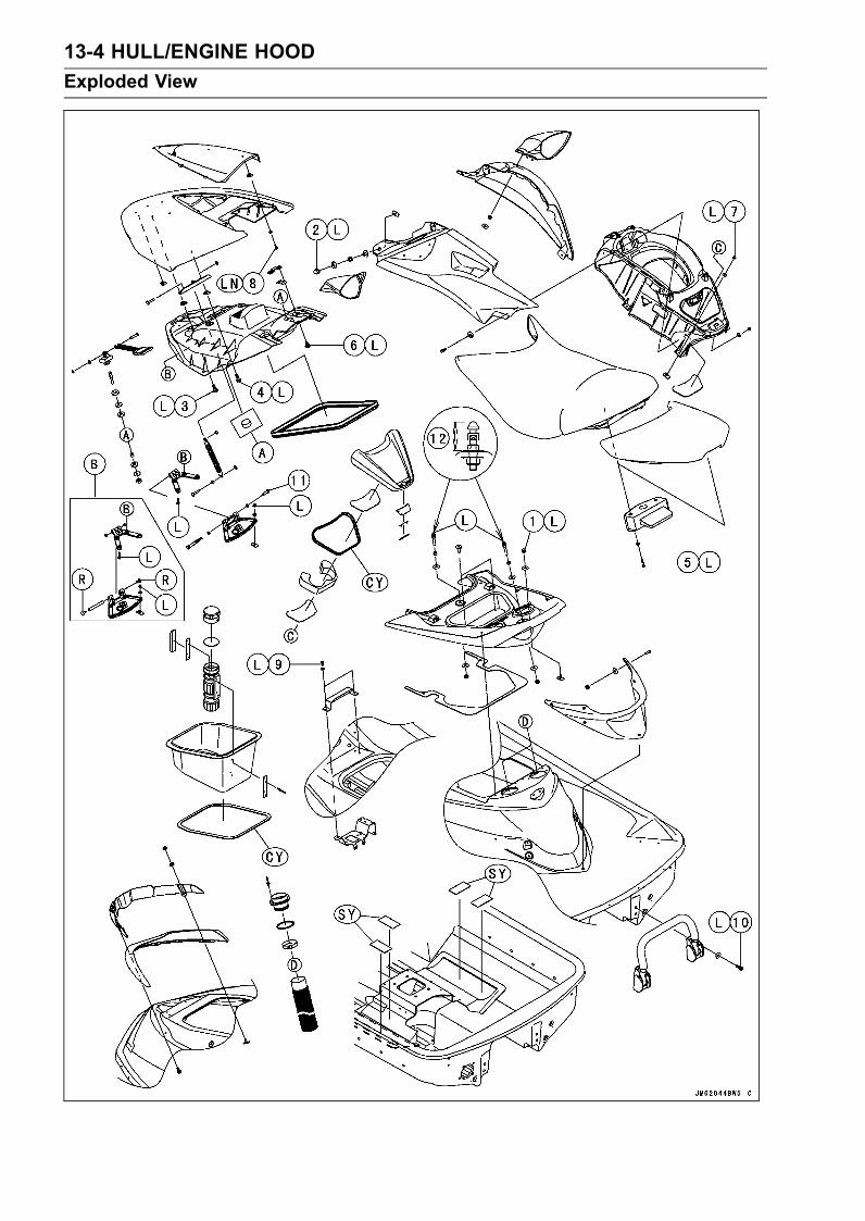
13-4 HULL/ENGINE HOODExploded View
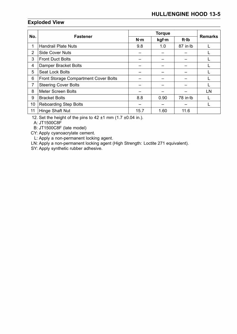
HULL/ENGINE HOOD 13-5Exploded View
TorqueNo. Fastener
N·m kgf·m ft·lbRemarks
1 Handrail Plate Nuts 9.8 1.0 87 in·lb L2 Side Cover Nuts – – – L3 Front Duct Bolts – – – L4 Damper Bracket Bolts – – – L5 Seat Lock Bolts – – – L6 Front Storage Compartment Cover Bolts – – – L7 Steering Cover Bolts – – – L8 Meter Screen Bolts – – – LN9 Bracket Bolts 8.8 0.90 78 in·lb L10 Reboarding Step Bolts – – – L11 Hinge Shaft Nut 15.7 1.60 11.612. Set the height of the pins to 42 ±1 mm (1.7 ±0.04 in.).A: JT1500C8FB: JT1500C8F (late model)CY: Apply cyanoacrylate cement.L: Apply a non-permanent locking agent.LN: Apply a non-permanent locking agent (High Strength: Loctite 271 equivalent).SY: Apply synthetic rubber adhesive.

13-6 HULL/ENGINE HOODFittings
Seat Removal•Pull up [A] the latch handle [B].
• Remove the rear seat up [A] and to the rear [B].
• Pull up [A] the latch handle [B].
• Remove the front seat up [A] and to the rear [B].
Seat Installation• Insert the seat hook [A] into the bracket [B] on the deckand slide it all the way forward by pushing the rear of theseat.• Push down on the rear of the seat to lock it.

HULL/ENGINE HOOD 13-7Fittings
• Insert the seat hook [A] into the brackets [B] on thehandrail plate and slide it all the way forward by pushingthe rear of the seat.• Push down on the rear of the seat to lock it.
Front Storage Compartment Cover Removal•Pull [A] the latch handle [B].•Open [C] the front storage compartment cover [D].
• Remove:Hinge Bracket Nuts [A] and WashersFront Storage Compartment Cover Assembly [B]
Front Storage Compartment Cover Disassembly•Remove:Hinge Bolts [A]Front Duct Bolts [B]Damper Washer [C]Damper Pin [D]Hinge [E]Front Duct [F]

13-8 HULL/ENGINE HOODFittings
•Remove:Lock Assembly Nut [A]Lock Assembly Bolts [B]BracketLock Assembly [C]
• Remove:Screen Bolts [A]Screen [B]
Front Storage Compartment Cover Assembly•When installing the screen [A] on the front storage com-partment cover, insert its projection [B] into the recess [C]on the front storage compartment cover.• Apply a non-permanent locking agent to the screen boltsand the damper bracket bolts, and tighten them securely.
• Align the projections [A] on the lock assembly with theholes [B] on the duct.• Apply a non-permanent locking agent to lock assemblybolts and tighten them securely.

HULL/ENGINE HOOD 13-9Fittings
• Insert the front duct portions [A] indicated in the figure intothe ribs [B] of the front storage cover.• Apply a non-permanent locking agent to the front ductbolts and hinge bolts, and tighten them securely.
• If the hinge bracket [A] is disassembled, apply a water-resistant grease [B] to the following.Bushings [C]Shaft [D]Hinge Shaft Nut [E]Torque - Hinge Shaft Nut: 15.7 N·m (1.60 kgf·m, 11.6 ft·lb)
• JT1500C8F (late model)If the hinge bracket [A] is disassembled, apply a water-resistant grease [B] to the following.Bushings [C]Shaft [D]
Replace the rivets [E] with new ones.

13-10 HULL/ENGINE HOODFittings
Center Storage Lid Removal/Installation•Open the middle storage lid [A].• Pull up [B] the lid.• Installation is the reverse of removal.
• To remove the lock [A] from the center storage lid, turnand pull out the shaft [B] (both side).•When installing the shafts, push the shaft end [C] (bothside) into the hollow [D] on the lock.
Side Cover Removal•To remove the right side cover, remove the following.Center storage Lid (see Center Storage Lid Removal/In-stallation)Side Cover Nuts [A] and Washers
•Disconnect the rear end [A] of the flushing line.
• To remove the left side cover, remove the following.• Remove the fuel filler cap [A].

HULL/ENGINE HOOD 13-11Fittings
•Pull up the tilt lever [A].• Take out the side cover nuts [B] and washers, remove theleft side cover [C].
Side Cover Installation• Installation is the reverse of removal, noting the following.Be sure that the rear end of flushing line is connected withits fitting surely.
Front Access Cover Removal/Installation•Open the front storage compartment cover.• Remove the front storage case.• Push in the pins [A] and remove the front access cover[B].
• To install the front access cover, pull up the pin head [A]as shown and install the rivet [B].
• Push in [A] the pin.

13-12 HULL/ENGINE HOODFittings
Center Access Cover Removal/Insatallation•Remove the steering cover (see Steering Removal).• Pull out the center access cover [A].
Mirror Removal/Installation•Remove the side cover (see Side Cover Removal).• Unscrew the nuts [A] and washers [B] and remove themirrors [C] (both sides).• Installation is the reverse of removal.
Handrail Plate Removal•Remove the rear and front seats (see Seat Removal).• Take out the handrail plate nuts [A] and washers [B], andremove the handrail plate [C].
Handrail Plate Installation•Be sure that the plugs [A] and the damper [B] are in posi-tion.

HULL/ENGINE HOOD 13-13Fittings
Handrail Removal/Installation•Remove the rear and front seats (see Seat Removal).• Disconnect the bilge hoses from the breather fitting.• Remove the rear air ducts (see Air Duct Removal).• Take out the nuts [A] and washers [B], remove thehandrail [C].
Drain Plug Housing Removal•Unscrew the screws [A] and remove the drain plug hous-ing [B].
Drain Plug Housing Installation•Check the seal [A] for damage.If necessary, replace new ones.Install the new gasket [B] so that its “OUT” mark [C] facesoutwards.
Exhaust Outlet Removal•Unscrew the mounting bolts [A] and remove the holder [B]and exhaust outlet [C].
Exhaust Outlet Installation•Apply a non-permanent locking agent to the mountingbolts and tighten them securely.

13-14 HULL/ENGINE HOODFittings
Stabilizer Removal•Unscrew the stabilizer bolts [A] and remove the stabilizer[B].
Stabilizer Installation•Apply a non-permanent locking agent (High Strength:Loctite 271 equivalent) to the stabilizer bolt and torquethem.Torque - Stabilizer Bolts: 9.8 N·m (1.0 kgf·m, 87 in·lb)
Reboarding Step Removal•Unscrew the reboarding step bolts [A] and remove thereboarding step [B].
Reboarding Step Installation•Apply a non-permanent locking agent to the reboardingstep bolts and tighten them securely.

HULL/ENGINE HOOD 13-15Hull Replacement
To replace the hull, remove the various parts in the follow-ing suggested order.Battery and PadExhaust PipeInlet ManifoldEngine and MountsAir FilterWater Box MufflerDrive Shaft and Shaft HolderPump and HosesSteering CoverHandlebar and SteeringSteering CableReverse CableFuel Tank and FillerBilge and Cooling System HoseBypass Hose and OutletBumpersEngine Hood LatchFront Storage Compartment Cover and BracketsAir DuctsHandrail
The following parts cannot be removed from the hull andmust be replaced.DecalsLabelsMatsRegistration Number (if any)
If the new hull is to be painted, do that first. Then installremoved parts in the reverse order of their removal. Finally,install the labels, decals, mats and the registration numbers.

13-16 HULL/ENGINE HOODRubber Parts
NOTEThe rubber parts on the watercraft are fastened in placewith various adhesives. To replace a rubber part, use acement in the following table, or an equivalent.
WARNINGRead all warnings and cautions on any solventsand adhesives used. Many of these products areflammable, may be harmful to the skin and eyes,and may give off harmful vapors. Use these sol-vents and adhesives only in a well-ventilated areaand never near an open flame.
For this Application TypeMats Synthetic RubberFront and Rear Seats Gasket AdhesiveFront Storage Compartment Cover (P/N: 92104-3701)GasketDetents Cyanoacrylate CementHandlebar Grips
CAUTIONBe very careful that the part is positioned correctlywhen you apply the cement. It may be impossibleto reposition the part.
WARNINGDo not get any cyanoacrylate cement in your eyesor on your skin. If you do get some in your eyes,do not try to wash it out. Contact a physician im-mediately! If you do get some on your fingers, donot touch any other part of your body; your fingerswill stick to anything they touch. Allow the cementto cure and it will eventually wear off.
Rubber Parts LocationFront Seat Gasket [A]

HULL/ENGINE HOOD 13-17Rubber Parts
Rear Seat Gasket [A]
Front Storage Compartment Gasket [A]
Center Storage Compartment Gasket [A]
Mats [A]
Rivet Removal•Drill out the rivet with a drill bit [A] of the correct size.Rivet Removal Drill Bit Size5.0 mm (0.2 in.)
NOTEStop drilling when the rivet head [B] starts to turn withdrill bit.Tap the rivet out with a suitable punch and hammer.
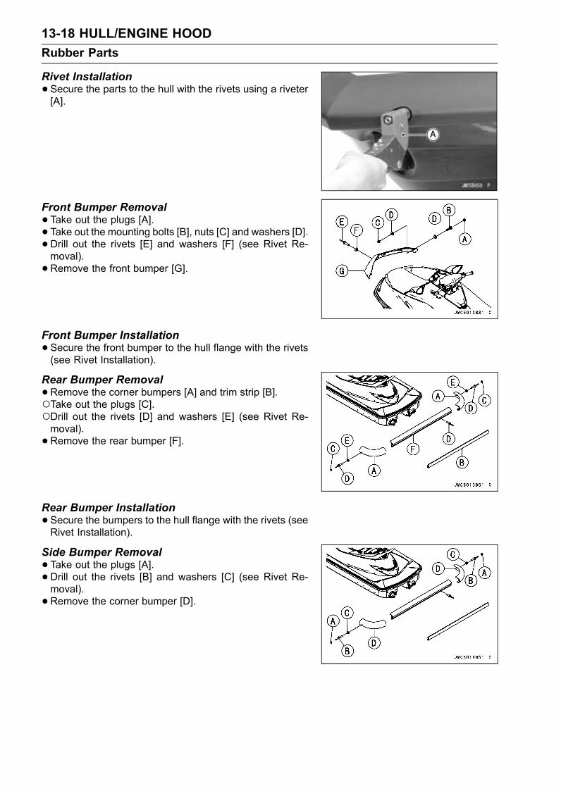
13-18 HULL/ENGINE HOODRubber Parts
Rivet Installation•Secure the parts to the hull with the rivets using a riveter[A].
Front Bumper Removal•Take out the plugs [A].• Take out the mounting bolts [B], nuts [C] and washers [D].• Drill out the rivets [E] and washers [F] (see Rivet Re-moval).• Remove the front bumper [G].
Front Bumper Installation•Secure the front bumper to the hull flange with the rivets(see Rivet Installation).
Rear Bumper Removal•Remove the corner bumpers [A] and trim strip [B].Take out the plugs [C].Drill out the rivets [D] and washers [E] (see Rivet Re-moval).• Remove the rear bumper [F].
Rear Bumper Installation•Secure the bumpers to the hull flange with the rivets (seeRivet Installation).
Side Bumper Removal•Take out the plugs [A].• Drill out the rivets [B] and washers [C] (see Rivet Re-moval).• Remove the corner bumper [D].

HULL/ENGINE HOOD 13-19Rubber Parts
•Remove the trim strip [A] from the side bumper [B].
• Drill out the rivets [A] (see Rivet Removal).
Side Bumper Installation•Secure the side bumpers to the hull flange with the rivets(see Rivet Installation).• Install the trim strip.
Air Duct Removal•To remove the front air ducts from the deck, remove thesteering cover (see Steering Removal in the Steeringchapter).• Drill out the rivets [A] (see Rivet Removal).• Remove:Clamp [B]Front Air Duct [C]Damper [D]Duct [E]

13-20 HULL/ENGINE HOODRubber Parts
•To remove the rear air ducts from the deck, remove thehandrail plate (see Handrail Plate Removal).• Drill out the rivets [A] (see Rivet Removal).• Remove:Clamp [B]Rear Air Duct [C]Damper [D]Duct [E]
Air Duct Installation•Secure the air duct to the deck with the rivets (see RivetInstallation).
ELECTRICAL SYSTEM 14-1
14
Electrical SystemTable of Contents
Parts Location......................................................................................................................... 14-3Exploded View........................................................................................................................ 14-6Wiring Diagram....................................................................................................................... 14-12Specifications ......................................................................................................................... 14-14Special Tools and Sealant ...................................................................................................... 14-15Precautions............................................................................................................................. 14-16Electrical Wiring...................................................................................................................... 14-17
Wiring Inspection .............................................................................................................. 14-17Battery .................................................................................................................................... 14-18
Battery Cover Removal/Installation................................................................................... 14-18Battery Removal ............................................................................................................... 14-18Battery Installation ............................................................................................................ 14-19Electrolyte Filling............................................................................................................... 14-19Initial Charge..................................................................................................................... 14-21Precautions ....................................................................................................................... 14-21Interchange....................................................................................................................... 14-22Charging Condition Inspection.......................................................................................... 14-22Refreshing Charge............................................................................................................ 14-22
Electric Starter System........................................................................................................... 14-24Starter Relay Removal...................................................................................................... 14-24Starter Relay Installation................................................................................................... 14-24Starter Relay Inspection.................................................................................................... 14-24Starter Motor Removal...................................................................................................... 14-25Starter Motor Installation................................................................................................... 14-25Starter Motor Disassembly................................................................................................ 14-26Starter Motor Assembly .................................................................................................... 14-26Brush Inspection ............................................................................................................... 14-27Commutator Cleaning and Inspection............................................................................... 14-27Armature Inspection.......................................................................................................... 14-28Brush Lead Inspection ...................................................................................................... 14-28Brush Plate and Terminal Bolt Inspection ......................................................................... 14-28Reduction Gear Removal/Installation ............................................................................... 14-29Reduction Gear Inspection ............................................................................................... 14-29
Charging System.................................................................................................................... 14-31Magneto Output Voltage ................................................................................................... 14-31Regulator/Rectifier Removal/Installation........................................................................... 14-31Regulator/Rectifier Inspection........................................................................................... 14-32Regulator Inspection ......................................................................................................... 14-32
Ignition System....................................................................................................................... 14-35Crankshaft Sensor Removal ............................................................................................. 14-35Crankshaft Sensor Installation .......................................................................................... 14-35Timing Rotor Removal ...................................................................................................... 14-36Timing Rotor Installation ................................................................................................... 14-36Crankshaft Sensor Inspection........................................................................................... 14-36Ignition Coil Removal ........................................................................................................ 14-37Ignition Coil Installation .................................................................................................... 14-38Ignition Coil Inspection...................................................................................................... 14-39Camshaft Position Sensor Removal ................................................................................. 14-40Camshaft Position Sensor Installation .............................................................................. 14-40Camshaft Position Sensor Inspection ............................................................................... 14-41

14-2 ELECTRICAL SYSTEM
Igniter Removal/Installation............................................................................................... 14-41Igniter Inspection............................................................................................................... 14-41Spark Plug Removal ......................................................................................................... 14-44Spark Plug Installation ...................................................................................................... 14-44Spark Plug Inspection ....................................................................................................... 14-44Spark Plug Adjustment ..................................................................................................... 14-44Spark Plug Cleaning ......................................................................................................... 14-44
Kawasaki Smart Steering System .......................................................................................... 14-47Steering Position Sensor and Magnet Removal ............................................................... 14-47Steering Position Sensor and Magnet Installation ............................................................ 14-47Inspection of Kawasaki Smart Steering System ............................................................... 14-48Steering Position Sensor Clearance................................................................................. 14-48Steering Position Sensor Input Voltage Inspection ........................................................... 14-49Steering Position Sensor Output Voltage Inspection ........................................................ 14-50
Sensors .................................................................................................................................. 14-52Speed Sensor Removal/Installation.................................................................................. 14-52Speed Sensor Inspection.................................................................................................. 14-53Fuel Level Sensor Inspection............................................................................................ 14-53Throttle Sensor Removal/Installation ................................................................................ 14-54Throttle Sensor Inspection ................................................................................................ 14-54Water Temperature Sensor Inspection ............................................................................. 14-55Inlet Air Temperature Sensor Inspection........................................................................... 14-55Oil Temperature Sensor Inspection................................................................................... 14-55
Multifunction Meter ................................................................................................................. 14-56Meter Unit Inspection ........................................................................................................ 14-56
Immobilizer System ................................................................................................................ 14-66Operational Cautions ........................................................................................................ 14-66Key Registration................................................................................................................ 14-66Immobilizer System Parts Replacement ........................................................................... 14-77Immobilizer System Inspection ......................................................................................... 14-78
Relay Assembly...................................................................................................................... 14-79Relay Assembly Removal ................................................................................................. 14-79Relay Assembly Installation .............................................................................................. 14-79Relay Assembly Inspection............................................................................................... 14-79
Switches ................................................................................................................................. 14-81Switch Inspection .............................................................................................................. 14-81
Fuse........................................................................................................................................ 14-82Inspection.......................................................................................................................... 14-82

ELECTRICAL SYSTEM 14-3Parts Location
1. Bow2. Ignition Coil #2, #33. Ignition Coil #1, #44. Crankshaft Sensor5. Magneto6. Starter Motor7. Fuse Case8. Regulator/Rectifier9. ECU (Electronic Control Unit)10. ECU Main Relay11. Fuel Pump Relay

14-4 ELECTRICAL SYSTEMParts Location
13. Water Temperature Sensor14. Camshaft Position Sensor15. Oil Temperature Sensor16. Oil Pressure Switch17. Speed Sensor

ELECTRICAL SYSTEM 14-5Parts Location
18. Fuel Level Sensor19. Steering Position Sensor20. Buzzer21. Multifunction Meter22. Starter Switch23. Engine Stop Switch24. Lanyard Key (Tether Code)25. Ignition Switch26. Starter Relay27. Battery

14-6 ELECTRICAL SYSTEMExploded View

ELECTRICAL SYSTEM 14-7Exploded View
TorqueNo. Fastener
N·m kgf·m ft·lbRemarks
1 Vehicle-down Sensor Mounting Screws 1.5 0.15 13 in·lb2 Bracket Bolts 8.8 0.90 78 in·lb L3 Starter Relay Case Bolts 7.8 0.80 69 in·lb4 Water Temperature Sensor 15 1.5 11 see text5 Starter Relay Mounting Nuts 3.5 ∼ 4.5 0.35 ∼ 0.45 30 ∼ 40 in·lb6 Starter Cable Mounting Nuts 3.5 ∼ 4.5 0.35 ∼ 0.45 30 ∼ 40 in·lb7 Oil Temperature Sensor 15 1.5 11 see text8 Camshaft Position Sensor Bolt 9.8 1.0 87 in·lb L9 Regulator/Rectifier Bolts 7.8 0.80 69 in·lb10 Relay Bolts 2.5 0.25 22 in·lb L11 ECU Mounting Bolts 3.0 0.3 27 in·lb L12 Fuse Bracket Bolt 2.5 0.25 22 in·lb LEO: Fill the hollow of the exhaust manifold with engine oil (10W-30).G: Apply grease.L: Apply a non-permanent locking agent.Si: Fill the hollow of the oil pan with the specified silicone grease (Kawasaki Bond: 92137-1002).

14-8 ELECTRICAL SYSTEMExploded View

ELECTRICAL SYSTEM 14-9Exploded View
TorqueNo. Fastener
N·m kgf·m ft·lbRemarks
1 Multifunction Meter Mounting Bolts 3.9 0.40 35 in·lb2 Start/stop Switch Case Mounting Screw 3.9 0.40 35 in·lb3 Speed Sensor Mounting Bolts 3.9 0.40 35 in·lb L4. Multifunction Meter5. Battery6. BuzzerG: Apply grease.

14-10 ELECTRICAL SYSTEMExploded View

ELECTRICAL SYSTEM 14-11Exploded View
TorqueNo. Fastener
N·m kgf·m ft·lbRemarks
1 Starter Motor Through Bolts 6.4 0.65 56 in·lb L, R2 Starter Motor Mounting Bolts 8.8 0.90 78 in·lb L3 Starter Motor Ground Bolt 8.8 0.90 78 in·lb4 Starter Motor Terminal Nut 8.8 0.90 78 in·lb5 Stator Coil Bolts 12 1.2 104 in·lb L6 Grommet Holder Bolts 8.8 0.90 78 in·lb L7 Ignition Coil Mounting Bolts 8.8 0.90 78 in·lb L8 Timing Rotor Bolt 20 2.0 14 L9 Crankshaft Sensor Screws 4.4 0.45 39 in·lb L10 Rubber Grommet Holder Screws 4.4 0.45 39 in·lb L11 Crankshaft Sensor Cover Bolts 7.8 0.80 69 in·lb12 Spark Plugs 13 1.3 113 in·lbG: Apply grease.L: Apply a non-permanent locking agent.M: Apply molybdenum disulfide grease.R: Replacement parts.
WG: Apply water resistant grease.

14-12 ELECTRICAL SYSTEMWiring Diagram

ELECTRICAL SYSTEM 14-13Wiring Diagram

14-14 ELECTRICAL SYSTEMSpecifications
Item Standard Service LimitBatteryType 12 V 18 Ah – – –
Electric Starter SystemStarter Motor:Brush Length 12 mm (0.4724 in.) 6.5 mm (0.2559 in.)Commutator Diameter 28 mm (1.1024 in.) 27 mm (1.063 in.)
Charging SystemRegulator/rectifier Output Voltage Battery Voltage 14 ∼ 15 V – – –Alternator Output Voltage 48 ∼ 72 V – – –Stator Coil Resistance 0.432 ∼ 0.648 Ω – – –
Ignition SystemIgnition Coil:Primary Winding Resistance 1.53 ∼ 2.07 Ω – – –Secondary Winding Resistance 12.50 ∼ 16.91 kΩ – – –
Spark Plug:Type NGK CR9EK – – –Gap 0.7 ∼ 0.8 mm (0.028 ∼ 0.031 in.) – – –
Crankshaft Sensor Resistance 408 ∼ 612 Ω – – –

ELECTRICAL SYSTEM 14-15Special Tools and Sealant
Hand Tester:57001-1394
Peak Voltage Adapter:57001-1415
Needle Adapter Set:57001-1457
Holder Attachment:57001-1547
Harness Adapter:57001-1562
Key Registration Unit:57001-1582
Flywheel & Pulley Holder:57001-1605
Kawasaki Bond (Silicone Sealant):56019-120
Kawasaki Bond (Silicone Grease):92137-1002

14-16 ELECTRICAL SYSTEMPrecautions
There are a number of important precautions that shouldbe followed servicing electrical systems.Do not reverse the battery cable connections. This willburn out the diodes on the electrical parts.Always check battery condition before condemning otherparts of an electrical system. A fully charged battery is amust for conducting accurate electrical system tests.The electrical parts should never be struck sharply, aswith a hammer, or allowed to fall on a hard surface. Sucha shock to the parts can damage them.To prevent damage to electrical parts, do not disconnectthe battery cables or any other electrical connectionswhen the ignition switch is on, or while the engine isrunning.Because of the large amount of current, never keep thestarter button pushed when the starter motor will not turnover, or the current may burn out the starter motor wind-ings.Do not use a meter illumination bulb rated for other thanvoltage or wattage specified in the wiring diagram, as themeter or gauge panel could be warped by excessive heatradiated from the bulb.Take care not to short the leads that are directly con-nected to the battery positive (+) terminal to the chassisground.Troubles may involve one or in some cases all items.Never replace a defective part without determining whatCAUSED the failure. If the failure was caused by someother item or items, they must be repaired or replaced, orthe new replacement will soon fail againMake sure all connectors in the circuit are clean and tight,and examine leads for signs of burning, fraying, etc. Poorleads and bad connections will affect electrical systemoperation.Measure coil and winding resistance when the part is cold(at room temperature).
Color CodesBK: BlackBL: BlueBR: BrownCH: ChocolateDG: Dark GreenG: GreenGY: GrayLB: Light Blue
LG: Light GreenO: OrangeP: PinkPU: PurpleR: RedW: WhiteY: Yellow
Connect the connectors with the same colored [A] and thesame number of pins [B] connectors.

ELECTRICAL SYSTEM 14-17Electrical Wiring
Wiring Inspection•Visually inspect the wiring for signs of burning, fraying,etc.If any wiring is poor, replace the damaged wiring.• Pull each connector [A] apart and inspect it for corrosion,dirt, and damage.If the connector is corroded or dirty, clean it carefully. If itis damaged, replace it.• Check the wiring for continuity.Use the wiring diagram to find the ends of the lead whichis suspected of being a problem.Connect the hand tester between the ends of the leads.Special Tool - Hand Tester: 57001-1394Set the tester to the × 1 Ω range, and read the tester.If the tester does not read 0 Ω, the lead is defective. Re-place the lead or the wiring harness [B] if necessary.
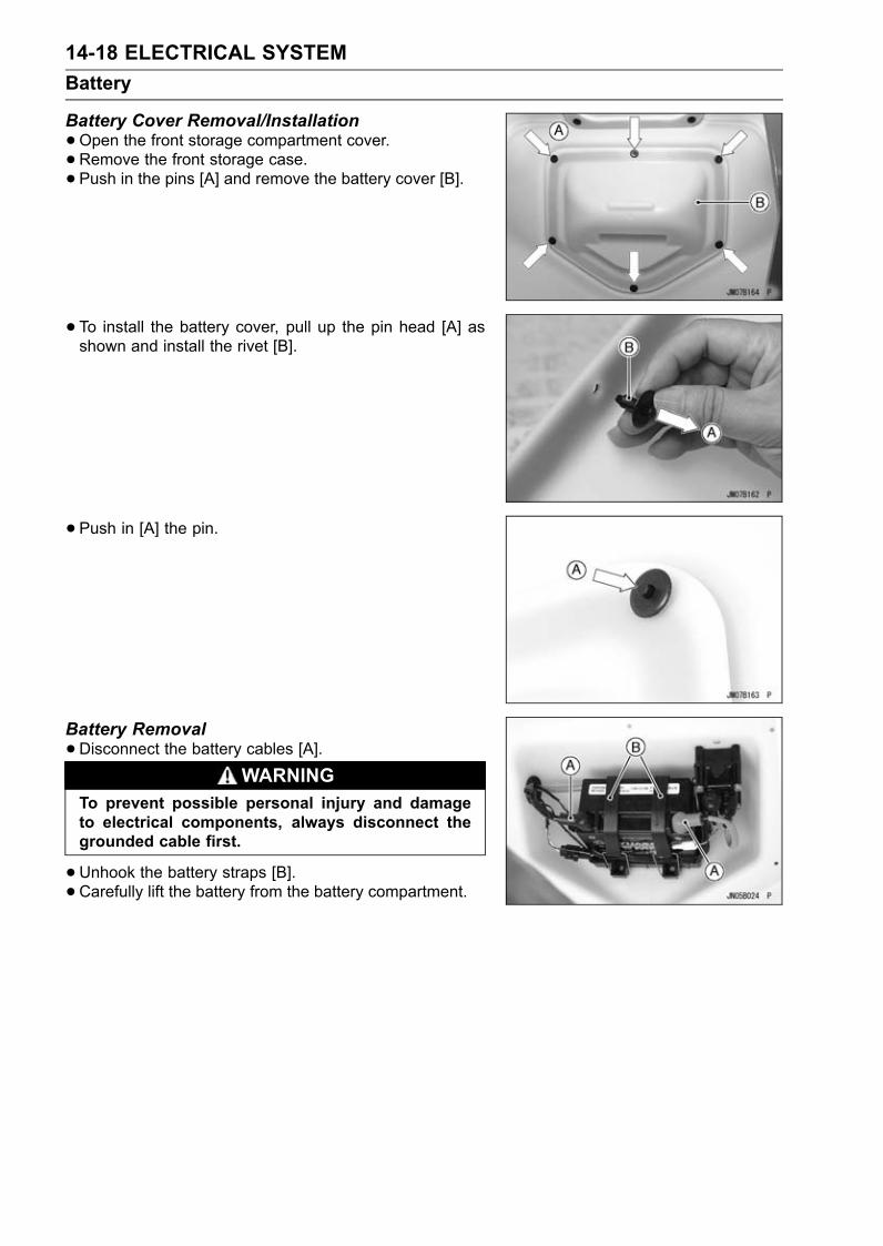
14-18 ELECTRICAL SYSTEMBattery
Battery Cover Removal/Installation•Open the front storage compartment cover.• Remove the front storage case.• Push in the pins [A] and remove the battery cover [B].
• To install the battery cover, pull up the pin head [A] asshown and install the rivet [B].
• Push in [A] the pin.
Battery Removal•Disconnect the battery cables [A].
WARNINGTo prevent possible personal injury and damageto electrical components, always disconnect thegrounded cable first.
•Unhook the battery straps [B].• Carefully lift the battery from the battery compartment.
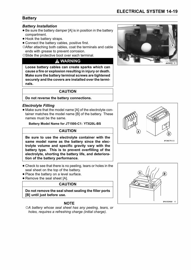
ELECTRICAL SYSTEM 14-19Battery
Battery Installation•Be sure the battery damper [A] is in position in the batterycompartment.• Hook the battery straps.• Connect the battery cables, positive first.After attaching both cables, coat the terminals and cableends with grease to prevent corrosion.Slide the protective boot over each terminal.
WARNINGLoose battery cables can create sparks which cancause a fire or explosion resulting in injury or death.Make sure the battery terminal screws are tightenedsecurely and the covers are installed over the termi-nals.
CAUTIONDo not reverse the battery connections.
Electrolyte Filling•Make sure that the model name [A] of the electrolyte con-tainer matches the model name [B] of the battery. Thesenames must be the same.Battery Model Name for JT1500-C1: YTX20L-BS
CAUTIONBe sure to use the electrolyte container with thesame model name as the battery since the elec-trolyte volume and specific gravity vary with thebattery type. This is to prevent overfilling of theelectrolyte, shorting the battery life, and deteriora-tion of the battery performance.
•Check to see that there is no peeling, tears or holes in theseal sheet on the top of the battery.• Place the battery on a level surface.• Remove the seal sheet [A].
CAUTIONDo not remove the seal sheet sealing the filler ports[B] until just before use.
NOTEA battery whose seal sheet has any peeling, tears, orholes, requires a refreshing charge (initial charge).

14-20 ELECTRICAL SYSTEMBattery
•Take the electrolyte container out of the vinyl bag.• Detach the strip of cap [A] from the container.
NOTEDo not discard the strip of cap because it is used as thebattery plugs later.Do not peel back or pierce the seals [B] on the container.
•Place the electrolyte container upside down aligning thesix seals with the six battery filler ports.• Push the container down strongly enough to break theseals. Now the electrolyte should start to flow into thebattery.
NOTEDo not tilt the container as the electrolyte flow may beinterrupted.
•Check the electrolyte flow.If no air bubbles [A] are coming up from the filler ports, orif the container cells have not emptied completely, tap thecontainer [B] a few times.• Keep the container in place for 20minutes or more. Don’tremove the container from the battery until it’s empty, thebattery requires all the electrolyte from the container forproper operation.
CAUTIONRemoval of the container before it is completelyempty can shorten the service life of the battery. Donot remove the electrolyte container until it is com-pletely empty and 20 minutes have elapsed.
•Gently remove the container from the battery.• Let the battery sit for 60minutes prior to charging to allowthe electrolyte to permeate into the plates for optimumperformance.
NOTECharging the battery immediately after filling canshorten service life. Let the battery sit for at least 60minutes after filling.

ELECTRICAL SYSTEM 14-21Battery
Initial Charge•Place the strip [A] of caps loosely over the filler ports.• Newly activated sealed batteries require an initial charge.
Standard Charge 1.8 A × 5 ∼ 10 hours
If using a recommended battery charger, follow thecharger’s instructions for newly activated sealed battery.
Kawasaki-recommended chargersOptimate IIIYuasa 1.5 Amp Automatic ChargerBattery Mate 150-9
If the above chargers are not available, use equivalentone.
NOTECharging rates will vary depending on how long thebattery has been stored, temperature, and the type ofcharger used. Let battery sit 30 minutes after initialcharge, then check voltage using a voltmeter. If it isnot at least 12.6 volts, repeat charging cycle.
•After charging is completed, press down firmly with bothhands to seat the strip of caps [A] into the battery (don’tpound or hammer). When properly installed, the strip ofthe caps will be level with the top of the battery.
CAUTIONOnce the strip of the caps [A] is installed onto thebattery, never remove the caps, nor add water orelectrolyte to the battery.
NOTETo ensure maximum battery life and customer satisfac-tion, it is recommended the battery be load tested atthree times its amp-hour rating for 15 seconds.Re-check voltage and if less than 12.6 volts repeat thecharging cycle and load test. If still below 12.6 volts thebattery is defective.
Precautions1) No need of topping-upNo topping-up is necessary in this battery until it ends its life under normal use. Forcibly prying off theseal cap to add water is very dangerous. Never do that.2) Refreshing charge
If an engine will not start, it indicates the battery has been discharged. Give refresh charge for5 to 10 hours with charge current shown in the specification (see this chapter).When a fast charge is inevitably required, do it following precisely the maximum charge current
and time conditions indicated on the battery.
CAUTIONThis battery is designed to sustain no unusual deterioration if refresh-charged accordingto the method specified above. However, the battery’s performance may be reduced no-ticeably if charged under conditions other than given above. Never remove the seal capduring refresh charge.If by chance an excessive amount of gas is generated due to overcharging, the relief valvereleases the gas to keep the battery normal.

14-22 ELECTRICAL SYSTEMBattery
3) When you do not use the watercraft for months:Give a refresh charge before you store the watercraft and store it with the negative lead re-
moved. Give a refresh charge once a month during storage.4) Battery life:
If the battery will not start the engine even after several refresh charges, the battery has ex-ceeded its useful life. Replace it (Provided, however, the watercraft’s starting system has noproblem).
WARNINGKeep the battery away from sparks and open flames during charging, since the batterygives off an explosive gas mixture of hydrogen and oxygen. When using a battery charger,connect the battery to the charger before turning on the charger.This procedure prevents sparks at the battery terminals which could ignite any batterygases.No fire should be drawn near the battery, or no terminals should have the tightening loos-ened.The electrolyte contains sulfuric acid. Be careful not to have it touch your skin or eyes. Iftouched, wash it off with liberal amount of water. Get medial attention if severe.
InterchangeA sealed battery can fully display its performance only when combined with a proper watercraft
electric system. Therefore, replace a sealed battery only on watercraft which was originally equippedwith a sealed battery.Be careful, if a sealed battery is installed on watercraft which had an ordinary battery as original
equipment, the sealed battery’s life will be shortened.
Charging Condition Inspection•Refer to Battery Charging Condition Inspection in the Pe-riodic Maintenance chapter.
Refreshing Charge•Remove the battery [A] (see Battery Removal).• Refresh-charge by following method according to the bat-tery terminal voltage.
WARNINGThis battery is sealed type. Never remove thestrip of cap [B] even at charging. Never add water.Charge with current and time as stated below.
Terminal Voltage: 11.5 ∼ less than 12.6 VStandard Charge: 1.8 A × 5 ∼ 10 h (see following chart)Quick Charge: 9.0 A × 1.0 h
CAUTIONIf possible, do not quick charge. If the quick chargeis done due to unavoidable circumstances, do stan-dard charge later on.
Terminal Voltage: less than 11.5 VCharging Method: 1.8 A × 20 h

ELECTRICAL SYSTEM 14-23Battery
NOTEIncrease the charging voltage to a maximum voltage of25 V if the battery will not accept current initially. Chargefor no more than five minutes at the increased voltagethen check if the battery is drawing current.If the battery will accept current, decrease the voltageand charge by the standard charging method describedon the battery case. If the battery will not accept currentafter 5 minutes, replace the battery.
Battery [A]Battery Charger [B]Standard Value [C]
• Determine battery condition after refreshing charge.Determine the condition of the battery 30 minutes aftercompletion of the charge by measuring the terminal volt-age according to the table below.
Criteria Judgement12.6 V or more Good12.0 ∼ less than 12.6 V Charge insufficient → Rechargeless than 12.0 V Unserviceable → Replace

14-24 ELECTRICAL SYSTEMElectric Starter System
Starter Relay Removal•Remove:Battery Cover (see Battery Cover Removal/Installationin the Hull/Engine Hood chapter)Battery (see this chapter)• Disconnect the negative battery cable from the batteryterminal. (see Battery Removal).• Disconnect the starter relay lead connector [A].• Slide out the rubber caps [B].• Remove the nuts [C] from the battery and starter terminalson the start relay switch.• Remove the starter relay case bolts [D] and slide thestarter relay switch from the relay case [E], being care-ful not to lose any of the insulating washers or grommets.
Starter Relay Installation•Mount the starter relay switch [A] in the relay case [B].Coat the insulating washers [C] and grommets [D] withwater resistant grease.Be certain all insulating washers and grommets are in po-sition.Tighten the relay mounting nuts [E] securely.Torque - Starter Relay Mounting Nuts: 4 N·m (0.40 kgf·m,
35 in·lb)
•Replace the gasket [A] with a new one.• Be sure the dowel pins [B] are in position.• Be sure the grommet [C] is installed on the relay case [D].• Be sure the battery cable is connected to the battery ter-minal having red mark.Torque - Starter Relay Case Bolts: 7.8 N·m (0.80 kgf·m, 69
in·lb)Starter Cable Mounting Nuts: 4 N·m (0.40 kgf·m,35 in·lb)
Starter Relay Inspection•Remove the starter relay (see Starter Relay Removal).• Set hand tester to R × 1 Ω range.• Connect meter leads to starter relay as shown.If resistance is less than infinite, the starter relay switch isnot returning and must be replaced.Special Tool - Hand Tester: 57001-1394

ELECTRICAL SYSTEM 14-25Electric Starter System
•Set ohmmeter to R × 1 Ω range.• Connect meter leads to starter relay as shown.• Activate starter relay switch by connecting a 12 V batteryas shown.If the starter relay switch clicks and the ohmmeter indi-cates zero resistance, the starter relay switch is good.If the meter indicates high or infinite (∞) resistance, thestarter relay switch is defective and must be replaced.
Starter Motor Removal•Remove:Seat (see Seat Removal in the Hull/Engine Hood chap-ter)Inlet Manifold (see Inlet Manifold Removal in the FuelSystem chapter)• Side out the rubber caps [A] and remove the terminal nuts.
• Remove the mounting bolts [A].• Pull out the starter motor [B].
Starter Motor InstallationCAUTION
Do not tap the starter motor shaft or body. Tappingthe shaft or body could damage the motor.
•When installing the starter motor, clean the starter mo-tor legs [A] and crankcase [B] where the starter motor isgrounded.
• Apply grease to the O-rings [A].• Install the starter motor and tighten the mounting bolts.Torque - Starter Motor Mounting Bolts: 8.8 N·m (0.90 kgf·m,
78 in·lb)

14-26 ELECTRICAL SYSTEMElectric Starter System
Starter Motor Disassembly•Remove the starter motor (see Starter Motor Removal).• Take off the starter motor through bolts [A] and removeboth end covers [B] and pull the armature out of the yoke[C].
• Remove the terminal locknut [A] and terminal bolt [B], andthen remove the brush with the brush plate [C] from theyoke.
Starter Motor Assembly•Apply a thin coat of grease to the oil seal [A].• Fit the toothed washer [B] into the end cover.
• Install the plate cover [A] and the positive brush assembly[B] in the yoke [C].• Tighten the terminal nut [D] securely.
• Holding the spring ends [A] with suitable plates [B], putthe armature among the brushes.

ELECTRICAL SYSTEM 14-27Electric Starter System
• Install the O-rings [A] and the washers [B] as shown.
• Fit the tongue [A] on the brush plate into the end covergroove [B].
• Align the lines [A] on the yoke with the lines [B] on theboth end covers.• Replace the starter motor through bolts [C] with new ones.• Tighten:Torque - Starter Motor Through Bolts: 6.4 N·m (0.65 kgf·m,
56 in·lb)
Brush Inspection•Measure the length [A] of each brush.If any is worn down to the service limit, replace the nega-tive brush assembly [B] and the positive brush assembly[C].
Starter Motor Brush LengthStandard: 12 mm (0.4724 in.)Service Limit: 6.5 mm (0.2559 in.)
Commutator Cleaning and Inspection•Smooth the commutator surface [A] if necessary with fineemery cloth [B], and clean out the grooves.

14-28 ELECTRICAL SYSTEMElectric Starter System
•Measure the diameter [A] of the commutator [B].Replace the starter motor with a new one if the commu-tator diameter is less than the service limit.
Commutator DiameterStandard: 28 mm (1.1024 in.)Service Limit: 27 mm (1.063 in.)
Armature Inspection•Using the × 1 Ω hand tester range, measure the resis-tance between any two commutator segments [A].Special Tool - Hand Tester: 57001-1394If there is a high resistance or no reading (∞) between anytwo segments, a winding is open and the starter motormust be replaced.• Using the highest hand tester range, measure the resis-tance between the segments and the shaft [B].If there is any reading at all, the armature has a short andthe starter motor must be replaced.
NOTEEven if the foregoing checks show the armature to begood, it may be defective in some manner not readilydetectable within the hand tester. If all other starter mo-tor and starter motor circuit components check good,but the starter motor still does not turn over or only turnsover weakly, replace the starter motor with a new one.
Brush Lead Inspection•Using the × 1 Ω hand tester range, measure the resis-tance as shown.[A] Terminal and Positive Brush[B] Brush Plate and Negative BrushSpecial Tool - Hand Tester: 57001-1394If there is not close to zero ohms, the brush lead has anopen. Replace the positive brush assembly and/or thenegative brush assembly.
Brush Plate and Terminal Bolt Inspection•Using the highest hand tester range, measure the resis-tance as shown.[A] Terminal Bolt and Brush Plate[B] Terminal Bolt and YokeIf there is any reading, the negative brush assemblyand/or positive brush assembly have a short. Replacethe negative and positive brush assemblies.

ELECTRICAL SYSTEM 14-29Electric Starter System
Reduction Gear Removal/Installation•Before removing the reduction gear, remove the magnetoflywheel (see Magneto Flywheel Removal in the EngineBottom End chapter).•When installing the reduction gear, apply a molybdenumdisulfide grease [A] to both ends of its shaft.
Reduction Gear Inspection•Rotate the pinion gear [A] counterclockwise. The gearmust be rotated freely [B].
• Rotate the pinion gear clockwise all the way. The piniongear will be advanced along the reduction gear shaft, andstopped against the stopper [A].• Release the pinion gear. The pinion gear must return tothe initial position rapidly.If the pinion gear does not function properly, replace it.

14-30 ELECTRICAL SYSTEMElectric Starter System
Electric Starter Circuit
1. ECU2. Joint Connector 8 (Vcc)3. Joint Connector 7 (Vcc)4. System Relay5. Main (ECU) Relay6. Joint Connector 3 (Switch (12V))7. Joint Connector 28. Joint Connector 19. Engine Stop Switch/Tether10. Engine Start Switch11. Joint Connector 1312. Joint Connector 12 (Ground)13. Starter Relay14. Starter Motor15. Battery16. Main Fuse 20A

ELECTRICAL SYSTEM 14-31Charging System
Magneto Output Voltage•Remove:Seat (see Seat Removal in the Hull/Engine Hood chap-ter)Air Filter with Duct (see Air Filter Removal in the FuelSystem chapter)• Disconnect the 3-pin stator coil leads connector [A].
•With the hand tester [A] check the magneto output (incircuit) according to the following table with the enginerunning at approximately 3 000 rpm.
WARNINGTo avoid electrical shock, do not perform this testwith the watercraft in the water.
CAUTIONDo not run the engine over 15 secondswithout cool-ing water.
Magneto Output VoltageConnections
Meter SettingMeter (+) to Meter (–) to
Standard Value
250 V AC White lead White lead 48 ∼ 72 V
If the magneto output voltage is correct, check the regu-lator according to the regulator test procedure.If the magneto output voltage is low, check the stator coilresistance with a multimeter according to the followingtable.
Stator Coil Resistance TestConnections
Meter SettingMeter (+) to Meter (–) to
Standard Value
R × 1 Ω White lead White lead 0.432 ∼ 0.648 Ω
If the coil has normal resistance, but the voltage checkshows the charging system to be defective, then thepermanent magnets in the flywheel have probably weak-ened, necessitation flywheel replacement.
Regulator/Rectifier Removal/Installation•Remove the seat (see Hull/Engine Hood chapter).• Disconnect the connector [A].• Unscrew the mounting bolts [B] and remove the regula-tor/rectifier [C].
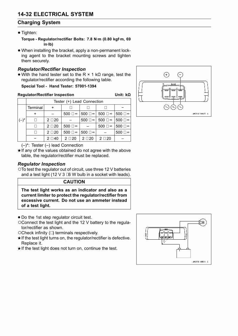
14-32 ELECTRICAL SYSTEMCharging System
•Tighten:Torque - Regulator/rectifier Bolts: 7.8 N·m (0.80 kgf·m, 69
in·lb)
•When installing the bracket, apply a non-permanent lock-ing agent to the bracket mounting screws and tightenthem securely.
Regulator/Rectifier Inspection•With the hand tester set to the R × 1 kΩ range, test theregulator/rectifier according the following table.Special Tool - Hand Tester: 57001-1394
Regulator/Rectifier Inspection Unit: kΩTester (+) Lead Connection
Terminal + ∼ ∼ ∼ −+ – 500 ∼ ∞ 500 ∼ ∞ 500 ∼ ∞ 500 ∼ ∞
(–)* ∼ 2 ∼ 20 – 500 ∼ ∞ 500 ∼ ∞ 500 ∼ ∞∼ 2 ∼ 20 500 ∼ ∞ – 500 ∼ ∞ 500 ∼ ∞∼ 2 ∼ 20 500 ∼ ∞ 500 ∼ ∞ – 500 ∼ ∞− 2 ∼ 40 2 ∼ 20 2 ∼ 20 2 ∼ 20 –
(–)*: Tester (–) lead ConnectionIf any of the values obtained do not agree with the abovetable, the regulator/rectifier must be replaced.
Regulator InspectionTo test the regulator out of circuit, use three 12 V batteriesand a test light (12 V 3 ∼ 6 W bulb in a socket with leads).
CAUTIONThe test light works as an indicator and also as acurrent limiter to protect the regulator/rectifier fromexcessive current. Do not use an ammeter insteadof a test light.
•Do the 1st step regulator circuit test.Connect the test light and the 12 V battery to the regula-tor/rectifier as shown.Check infinity (∼ ) terminals respectively.If the test light turns on, the regulator/rectifier is defective.Replace it.If the test light does not turn on, continue the test.

ELECTRICAL SYSTEM 14-33Charging System
•Do the 2nd step regulator circuit test.Connect the test light and the 12 V battery in the samemanner as specified in the “1st step regulator circuit test”.Apply 12 V to the positive (+) terminal.Check infinity (∼ ) terminals respectively.If the test light turns on, the regulator/rectifier is defective.Replace it.If the test light does not turn on, continue the test.
• Do the 3rd step regulator circuit test.Connect the test light and the 12 V battery in the samemanner as specified in the “1st step regulator circuit test”.Momentarily apply 24 V to the positive (+) terminal byadding a 12 V battery.Check infinity (∼ ) terminals respectively.
CAUTIONDo not apply more than 24 volts. If more than 24volts is applied, the regulator/rectifier may be dam-aged. Do not apply 24 V more than a few seconds.If 24 volts is applied for more than a few seconds,the regulator/rectifier may be damaged.
If the test light does not light when 24 V is applied momen-tarily to the positive (+) terminal, the regulator/rectifier isdefective. Replace it.If the regulator/rectifier passes all the tests described, itmay still be defective. If the charging system still doesnot work properly after checking all the components andthe battery, test the regulator/rectifier by replacing it witha known good unit.• Repeat the test for another regulator/rectifier.
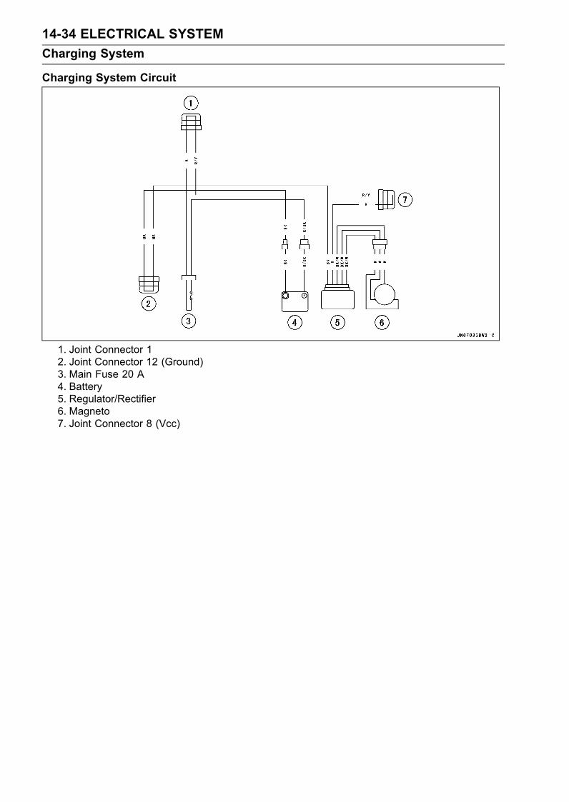
14-34 ELECTRICAL SYSTEMCharging System
Charging System Circuit
1. Joint Connector 12. Joint Connector 12 (Ground)3. Main Fuse 20 A4. Battery5. Regulator/Rectifier6. Magneto7. Joint Connector 8 (Vcc)

ELECTRICAL SYSTEM 14-35Ignition System
WARNINGThe ignition system produces extremely high volt-age. Do not touch the spark plugs, ignition coils, orspark plug leads while the engine is running, or youcould receive a severe electrical shock.
CAUTIONDo not disconnect the battery cables or any otherelectrical connections when the ignition switch ison, or while the engine is running. This is to preventECU (Electronic Control Unit) damage.Do not install the battery backwards. The negativeside is grounded. This is to prevent damage to thediodes and ECU.
Crankshaft Sensor Removal•Remove:Engine (see Engine Removal in the Engine Removal/In-stallation chapter)Crankshaft Sensor Cover Bolts [A]Crankshaft Cover [B]
• Unscrew:Rubber Grommet Holder Screws [A]Crankshaft Sensor Screws [B]• Push out the rubber grommet [C] with the Holder [D].• Remove the crankshaft sensor [E].
Crankshaft Sensor Installation•Run the sensor lead through the cover hole.• Install the crankshaft sensor [A].Apply a non-permanent locking agent to the sensorscrews.Torque - Crankshaft Sensor Screws: 4.4 N·m (0.45 kgf·m,
39 in·lb)
• Install the rubber grommet [B] in the sensor cover hole.Apply water resistant grease to the grommet outside.Apply a non-permanent locking agent to the grommetholder screws.Run the sensor lead [C] as shown.Torque - Rubber Grommet Holder Screws: 4.4 N·m (0.45
kgf·m, 39 in·lb)

14-36 ELECTRICAL SYSTEMIgnition System
•Apply grease to the O-ring and fit it in the groove of thesensor cover.• Apply silicone sealant [A] to the crankcase halves matingsurface on the right and left sides of the crankshaft sensormount.Sealant - Kawasaki Bond (Silicone Sealant): 56019-120
• Install the crankshaft sensor cover.Torque - Crankshaft Sensor Cover Bolts: 7.8 N·m (0.80
kgf·m, 69 in·lb)
• Install the Engine (see Engine Removal/Installation chap-ter).
Timing Rotor Removal•Remove the engine (see Engine Removal in the EngineRemoval/Installation chapter).• Remove the crankshaft sensor cover (see CrankshaftSensor Removal).• Remove the timing rotor [A].Holding the timing rotor with the flywheel and pulley holder[B] and unscrew the bolt [C].Special Tools - Flywheel & Pulley Holder: 57001-1605
Flywheel and Pulley Holder Adapter: 57001-1547 [D]
Timing Rotor Installation•Fit the rotor to the crankshaft.• Apply a non-permanent locking agent to the rotor bolt.• Tighten the rotor bolt.Torque - Timing Rotor Bolt: 20 N·m (2.0 kgf·m, 14 ft·lb)
• Install the crankshaft sensor cover (see Crankshaft Sen-sor Cover Installation).
Crankshaft Sensor Inspection•Remove:Seat (see Seat Removal in the Hull/Engine Hood chap-ter)• Disconnect the 2-pin crankshaft sensor leads connector(Blue) [A].
• Set the hand tester to the × 100 Ω range, zero it, andconnect it to the crankshaft sensor lead terminals (G andBL) in the connector.If there is more resistance than the specified value, thesensor has an open lead and must be replaced. Muchless than this resistancemeans the sensor is shorted, andmust be replaced.
Crankshaft Sensor ResistanceStandard: 408 ∼ 612 Ω

ELECTRICAL SYSTEM 14-37Ignition System
Ignition Coil Removal•Remove:Seat (see Seat Removal in the Hull/Engine Hood chap-ter)• Disconnect the ignition coil primary lead connectors [A].
• Remove the bracket bolts [A].
• Disconnect the regulator/rectifier lead connector [A] andvehicle-down sensor lead connector [B].
• Pull up the bracket [A] together with the ignition coils[B], vehicle-down sensor [C], and regulator/rectifier [D]installed.• Unscrew the nuts [E] and remove the bolts, collars [F] andignition coils.
• Pull out the spark plug lead [B] from the ignition coil [A].Lubricate the leads with penetrating rust inhibitor.

14-38 ELECTRICAL SYSTEMIgnition System
Ignition Coil Installation•Connect the spark plug lead to each ignition coil as fol-lows.#1 Spark Plug Lead Length 340 mm (13.4 in.) [A]#2 Spark Plug Lead Length 450 mm (17.7 in.) [B]#3 Spark Plug Lead Length 540 mm (21.3 in.) [C]#4 Spark Plug Lead Length 600 mm (23.6 in.) [D]
Marked [E] is a number of each lead• Apply a non-permanent locking agent to the ignition coilmounting bolts.• Install the #1, 4 ignition coil [F] and #2, 3 ignition coil [G]to the bracket [H].Torque - Ignition Coil Mounting Bolts: 7.8 N·m (0.80 kgf·m,
69 in·lb)Apply a non-permanent locking agent to the bracket bolts.
• Install the removal parts.

ELECTRICAL SYSTEM 14-39Ignition System
Ignition Coil InspectionMeasuring arcing distanceThe most accurate test for determining the condition of
the ignition coil is made by measuring arcing distance.• Remove the ignition coil (see Ignition Coil Removal).• Connect the ignition coil [A] (with the spark plug cap leftinstalled on the spark plug lead) to the tester [B], andmea-sure the arcing distance.Auxiliary Wires [C]
WARNINGTo avoid extremely high voltage shocks, do nottouch the coil or lead.If the distance reading is less than the specified value, theignition coil or spark plug cap is defective.
3 Needle Arcing DistanceStandard: 7 mm (0.28 in.) or more
•To determine which part is defective, measure the arcingdistance again with the spark plug leads removed fromthe ignition coil (see Ignition Coil Removal).If the arcing distance is subnormal as before, the troubleis with the ignition coil itself. If the arcing distance is nownormal, the trouble is with the spark plug lead.
Measuring coil resistanceIf the Coil Tester is not available, the coil can be checked
for a broken or badly shorted winding with a hand tester.However, a hand tester can not detect layer shorts andshorts resulting from insulation breakdown under high volt-age.• Disconnect the primary leads from the coil terminals.•Measure the primary winding resistance as follows [A].Connect the tester between the coil terminals.Set the tester to the × 1 Ω range, and read the tester.•Measure the secondary winding resistance as follows [B].Remove the spark plug leads (see Ignition Coil Removal).Connect the tester between the secondary lead terminals.Set the tester to the × 1 kΩ, and read the tester.If the hand tester does not read as specified, replace thecoil.
Winding ResistanceStandard: Primary windings 1.53 ∼ 2.07 Ω
Secondary windings 12.50 ∼ 16.91 kΩ
If the tester reads are as specified, the ignition coil wind-ings are probably good. However, if the ignition systemstill does not perform as it should after all other compo-nents have been checked, test replace the coil with oneknown to be good.

14-40 ELECTRICAL SYSTEMIgnition System
Measuring spark plug lead resistance•Check the spark plug lead [A] for visible damage.If the spark plug lead is damaged, replace the spark pluglead.•Measure the lead resistance with the hand tester [B].Spark Plug Lead ResistanceStandard: 3.75 ∼ 6.25 kΩ
If the hand tester does not read as specified, replace thelead
Camshaft Position Sensor Removal•Remove:Seat (see Seat Removal in the Hull/Engine Hood chap-ter)• Cut off the clamp [A].• Disconnect the camshaft position sensor lead connector[B].
• Remove:Camshaft Position Sensor Bolt [A]Camshaft Position Sensor [B]
Camshaft Position Sensor Installation•Apply grease or engine oil to the O-ring on the camshaftposition sensor.• Tighten:Torque - Camshaft Position Sensor Bolt: 9.8 N·m (1.0
kgf·m, 87 in·lb)

ELECTRICAL SYSTEM 14-41Ignition System
Camshaft Position Sensor Inspection•Remove:Seat (see Seat Removal in the Hull/Engine Hood chap-ter)Camshaft Position Sensor Lead Connector [A] (discon-nect)• Set the hand tester [B] to the × 10 Ω range and connect itto the yellow and black leads in the connector.Special Tool - Hand Tester: 57001-1394If there is more resistance than the specified value, thesensor coil has an open lead andmust be replaced. Muchless than this resistance means the sensor coil is shorted,and must be replaced.Camshaft Position Sensor Resistance: 400 ∼ 460 Ω
•Using the highest resistance range of the tester, mea-sure the resistance between the camshaft position sensorleads and chassis ground.Any tester reading less than infinity (∞) indicates a short,necessitating replacement of the camshaft position sen-sor.
Igniter Removal/Installation•Refer to ECU Removal in the Fuel System (DFI) chapter.Igniter InspectionThe igniter is built in the ECU (Electronic Control Unit).
CAUTIONDo not disconnect the battery leads or any otherelectrical connections when the ignition switch ison, or while the engine is running. This is to preventigniter in the ECU damage.
Ignition Coil Primary Peak Voltage CheckNOTE
Be sure the battery is fully charged.•Remove:Seat (see Seat Removal in the Hull/Engine Hood chap-ter)
• Pull all the spark plug caps from the spark plugs.• Install the new spark plugs [A] into each plug caps [B],and ground them onto the engine.
NOTEMaintain the correct value of compression pressure forthe cylinder (Be sure to measure the voltage with thespark plug installed to the cylinder head).

14-42 ELECTRICAL SYSTEMIgnition System
•Remove:Front Storage Pocket (see Hull/Engine Hood chapter)• Install the peak voltage adapter [A] into the hand tester[B].
• Connect the peak voltage adapter [A] to the ignition coilprimary lead connector [D], using the harness adapter [C].Hand Tester [B]Ignition Coil [E]Spark Plugs [F]Special Tools - Hand Tester: 57001-1394
Harness Adapter: 57001-1562Peak Voltage Adapter: 57001-1415Type: KEK-54-9-B
Hand Tester Range: × DC 1 000 V
Primary Lead ConnectionsAdapter Adapter(R, +) (BK, –)
#1, 4 Ignition Coil: R ←→ BK/W (Ground)#2, 3 Ignition Coil: R ←→ BK/W (Ground)
WARNINGTo avoid extremely high voltage shocks, do nottouch the spark plugs or tester connections.
•Turn the ignition switch on and push the lanyard key underthe stop button.• Pushing the starter button, crank the engine 4 ∼ 5 secondsto measure the primary peak voltage.Do not operate the starter for longer than 5 seconds. Wait15 seconds before using it again.• Repeat themeasurements 5 ormore times for one ignitioncoil.
Ignition Coil Primary Peak VoltageStandard: 250 V or more
•Repeat the test for the other ignition coil.If the reading is less than the specified value, see “Igni-tion System Troubleshooting” table to determine whetherigniter is good or no good.

ELECTRICAL SYSTEM 14-43Ignition System
Crankshaft Sensor Peak Voltage CheckNOTE
Be sure the battery is fully charged.•Connect the peak voltage adapter [A] to the hand tester[B].Special Tool - Peak Voltage Adapter: 57001-1415
Type: KEK-54-9-B
•Connect the adapter the crankshaft sensor lead connec-tor [C], using the needle adapter set [D].Special Tools - Hand Tester: 57001-1394
Needle Adapter Set: 57001-1457
ConnectionsAdapter Adapter(R, +) (BK, –)
Crankshaft Sensor: G ←→ BL
Hand Tester Range: × DC 10 V
•Turn the ignition switch on and push the lanyard key underthe stop button.• Pushing the starter button, crank the engine 4 ∼ 5 secondsto measure the crankshaft sensor peak voltage.Do not operate the starter for longer than 5 seconds. Wait15 seconds before using it again.• Repeat the measurements 5 or more times.Crankshaft Sensor Peak VoltageStandard: 2.5 V or more
If the reading is less than the specified value, check thecrankshaft sensor (see Crankshaft Sensor Inspection).
Camshaft Position Sensor Peak Voltage Inspection•Remove:Seat (see Hull/Engine Hood chapter)
• Set the digital meter [B] to the 10 V DC range.• Connect the peak voltage adapter [C] to the digital meter.Special Tool - Peak Voltage Adapter: 57001-1415
Type: KEK-54-9-B
•Connect the peak voltage adapter to the camshaft sensorlead connector [D], using the needle adapter set [A].Special Tool - Needle Adapter Set: 57001-1457
ConnectionsCamshaft Sensor Lead Adapter Hand Tester
Black ← Red → (+)Yellow ← Black → (−)
•Turn the ignition switch and engine stop switch on.• Pushing the starter button, turn the engine 4 ∼ 5 secondsto measure the camshaft position sensor peak voltage.• Repeat the measurement 5 or more times.Camshaft Position Sensor Peak VoltageStandard: 0.4 V or more
If the peak voltage is lower than the standard, inspect thecamshaft position sensor.

14-44 ELECTRICAL SYSTEMIgnition System
Spark Plug Removal•Refer to Spark Plug Inspection in the Periodic Mainte-nance chapter.
Spark Plug Installation•Refer to Spark Plug Inspection in the Periodic Mainte-nance chapter.
Spark Plug Inspection•Refer to Spark Plug Inspection in the Periodic Mainte-nance chapter.
Spark Plug Adjustment•Refer to Spark Plug Adjustment in the Periodic Mainte-nance chapter.
Spark Plug Cleaning•Refer to Spark Plug Cleaning in the Periodic Maintenancechapter.

ELECTRICAL SYSTEM 14-45Ignition System
Ignition System Circuit
1. ECU2. Joint Connector 8 (Vcc)3. Joint Connector 7 (Vcc)4. System Relay5. Main (ECU) Relay6. Joint Connector 3 (Switch(12 V))
7. Joint Connector 28. Joint Connector 1
9. Ignition Switch (Immobi-lizer Amplifier)
10. Joint Connector 15(Ground)
11. Engine StopSwitch/Tether
12. Engine Start Switch13. Joint Connector 13
14. Joint Connector 12(Ground)
15. Ignition Coils16. Spark Plugs17. Joint Connector 10 (Igni-
tion Coil (12 V))18. Battery19. Main Fuse 20 A

14-46 ELECTRICAL SYSTEMIgnition System

ELECTRICAL SYSTEM 14-47Kawasaki Smart Steering System
Steering Position Sensor and Magnet Removal•Remove the steering holder (see Steering Removal inSteering chapter).• Remove or disconnect:Steering Position Sensor Lead Connector [A]Leads Clamp on Steering HolderSteering Position Sensor Mounting Screws [B]Steering Position Sensor [C]
• Unscrew the mounting screw [A] and remove the magnet[B].
Steering Position Sensor and Magnet Installation•Moving the steering shaft in the direction [A] and [B],check the steering shaft for excessive play.If necessary, adjust the steering shaft nut or replace thebushings.
• Apply a non-permanent locking agent to the steeringposition sensor mounting screws and magnet mountingscrew.• Install the steering position sensor [A] to the steeringholder and align the projection [B] on the magnet with thehole [C] on the steering shaft plate.

14-48 ELECTRICAL SYSTEMKawasaki Smart Steering System
•Turning the steering shaft fully in left and right direction,check whether the steering position sensor comes in con-tact with the magnet.• Check the clearance [A] between the steering positionsensor [B] and the magnet [C] with feeler gauge.
Steering Position Sensor ClearanceStandard: 0.5 ∼ 1.5 mm (0.02 ∼ 0.06 in.)
If necessary, adjust the steering shaft nut.• Check the operation of Kawasaki Smart Steering system.Inspection of Kawasaki Smart Steering System• Inspect the smart steering system with the watercraft inthe water.• Center the handlebar in the straight-ahead position .• Squeeze the throttle lever and allow it to approx. 4 000rpm or above for 4 seconds or more.• Release the throttle lever.•Within 1 second, turn the handlebar all the way to the leftor right and check the engine speed increases to approx.2 800 rpm.•Center the handlebar in the straight-ahead position, andcheck the engine speed decreases to an idle speed.If the Kawasaki Smart Steering system does not operatenormally, check the steering position sensor clearance.
Steering Position Sensor Clearance•Check the clearance [A] between the steering positionsensor [B] and the magnet [C] with feeler gauge.
Steering Position Sensor ClearanceStandard: 0.5 ∼ 1.5 mm (0.02 ∼ 0.06 in.)
If the clearance is the specified value, inspect steeringposition sensor input voltage.If necessary, adjust the steering shaft nut.

ELECTRICAL SYSTEM 14-49Kawasaki Smart Steering System
Steering Position Sensor Input Voltage Inspection•Measure the input voltage to the steering position sensor.
NOTEBe sure the battery is fully charged.Connect a digital voltmeter [A] to the lead connector [B]of the steering position sensor using the needle adapterset [C].Special Tool - Needle Adapter Set: 57001-1457
Connections to Steering Position Sensor ConnectorMeter (+)→ R/W TerminalMeter (–)→ BK Terminal
Turn the ignition switch ON.Center the handlebar in the straight-ahead position.Measure the input voltage.Steering Position Sensor Input VoltageStandard: Battery Voltage
Turn the ignition switch OFF.If the reading is good, inspect steering position sensoroutput voltage.If the reading is out of the standard, check the following.Battery Voltage20 A Main FusePower Source Wiring (see Steering Position Sensor Cir-cuit)
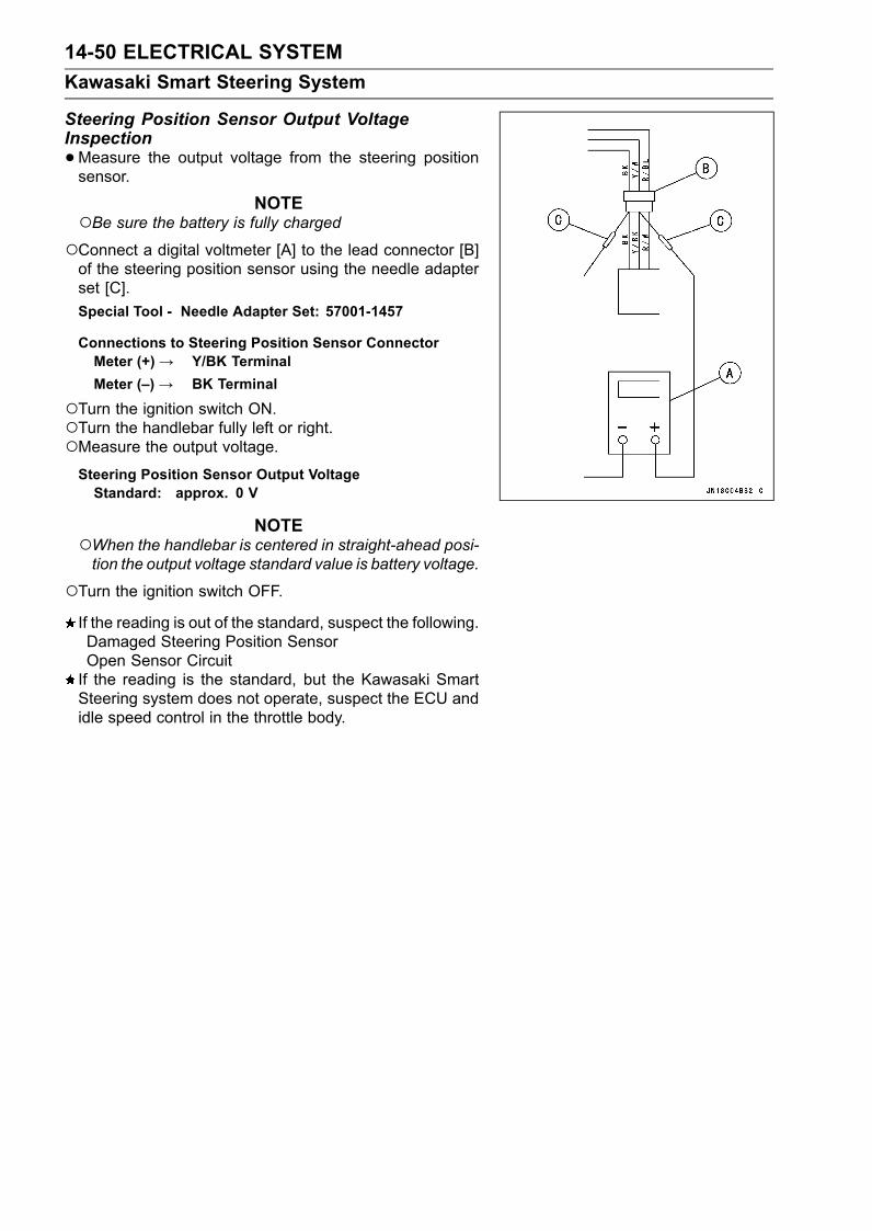
14-50 ELECTRICAL SYSTEMKawasaki Smart Steering System
Steering Position Sensor Output VoltageInspection•Measure the output voltage from the steering positionsensor.
NOTEBe sure the battery is fully chargedConnect a digital voltmeter [A] to the lead connector [B]of the steering position sensor using the needle adapterset [C].Special Tool - Needle Adapter Set: 57001-1457
Connections to Steering Position Sensor ConnectorMeter (+)→ Y/BK TerminalMeter (–)→ BK Terminal
Turn the ignition switch ON.Turn the handlebar fully left or right.Measure the output voltage.Steering Position Sensor Output VoltageStandard: approx. 0 V
NOTEWhen the handlebar is centered in straight-ahead posi-tion the output voltage standard value is battery voltage.
Turn the ignition switch OFF.If the reading is out of the standard, suspect the following.Damaged Steering Position SensorOpen Sensor CircuitIf the reading is the standard, but the Kawasaki SmartSteering system does not operate, suspect the ECU andidle speed control in the throttle body.

ELECTRICAL SYSTEM 14-51Kawasaki Smart Steering System
Steering Position Sensor Circuit
1. ECU2. Joint Connector 8 (Vcc)3. Joint Connector 7 (Vcc)4. System Relay5. Main (ECU) Relay6. Joint Connector 3 (Switch (12 V))7. Joint Connector 28. Joint Connector 19. Joint Connector 15 (Ground)10. Multifunction Meter11. Steering Position Sensor12. Joint Connector 1413. Joint Connector 1314. Battery15. Main Fuse 20 A

14-52 ELECTRICAL SYSTEMSensors
Speed Sensor Removal/Installation•Disconnect the speed sensor connector [A].
• Unscrew the mounting bolts [A] and remove the speedsensor assembly [B].
• Unscrew the cap [A].• Pull out the speed sensor connector and disconnect it.
•When installing the speed sensor assembly, note the fol-lowing.Apply silicone sealant around the grommet [A] and leadwires.
Install the speed sensor [A] as shown.Hull Bottom Line [B]5 mm (0.1969 in.) [C]

ELECTRICAL SYSTEM 14-53Sensors
Speed Sensor Inspection•Remove the speed sensor.• Connect the battery and tester leads to the sensor asshown.
•Rotate the waterwheel by hand slowly.•Measure the output voltage of the speed sensor.G/R (+), BK/W (–)→ 0 ∼ battery voltage; twice a rotation
(Rotate it slowly.)
If the voltage does not rise from zero to battery voltagetwice a rotation, replace the sensor.
•Measure the output voltage of the sensor at higherspeeds.Rotate the waterwheel in a fair speed by air.
G/R (+), BK/W (–) → approx. 5 V
If the sensor voltage does not reach 5 volts when spunwith compressed air, replace the sensor.
Fuel Level Sensor Inspection•Remove the fuel pump [A] (see Fuel Pump Removal inthe Fuel System (DFI) chapter).
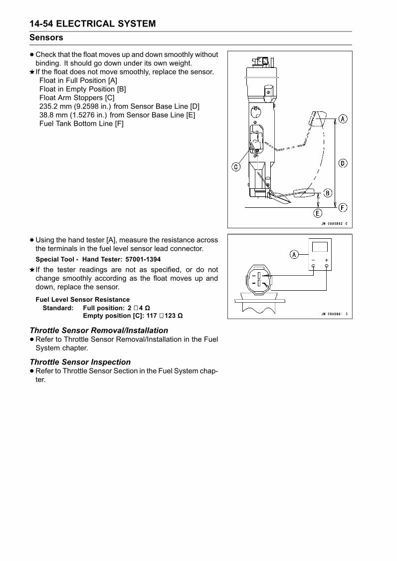
14-54 ELECTRICAL SYSTEMSensors
•Check that the float moves up and down smoothly withoutbinding. It should go down under its own weight.If the float does not move smoothly, replace the sensor.Float in Full Position [A]Float in Empty Position [B]Float Arm Stoppers [C]235.2 mm (9.2598 in.) from Sensor Base Line [D]38.8 mm (1.5276 in.) from Sensor Base Line [E]Fuel Tank Bottom Line [F]
• Using the hand tester [A], measure the resistance acrossthe terminals in the fuel level sensor lead connector.Special Tool - Hand Tester: 57001-1394If the tester readings are not as specified, or do notchange smoothly according as the float moves up anddown, replace the sensor.
Fuel Level Sensor ResistanceStandard: Full position: 2 ∼ 4 Ω
Empty position [C]: 117 ∼ 123 Ω
Throttle Sensor Removal/Installation•Refer to Throttle Sensor Removal/Installation in the FuelSystem chapter.
Throttle Sensor Inspection•Refer to Throttle Sensor Section in the Fuel System chap-ter.

ELECTRICAL SYSTEM 14-55Sensors
Water Temperature Sensor Inspection•Remove the water temperature sensor (see Fuel (DFI)System chapter).• Suspend the sensor [A] in a container of water so that thetemperature-sensing projection is submerged.• Suspend an accurate thermometer [B] in the water.
NOTEThe sensor and thermometer must not touch the con-tainer side or bottom.
•Place the container over a source of heat and graduallyraise the temperature of the water while stirring the watergently.• Using the hand tester, measure the internal resistance ofthe sensor at the temperatures shown in the table.If the hand tester does not show the specified values, re-place the sensor.
Water Temperature Sensor ResistanceWater Temperature Sensor Resistance
20°C (68°F) approx. 293 kΩ50°C (122°F) approx. 78.5 kΩ90°C (194°F) approx. 18.1 kΩ100°C (212°F) approx. 13.2 kΩ
Inlet Air Temperature Sensor Inspection•Refer to Inlet Air Temperature Sensor Section in the FuelSystem chapter.
Oil Temperature Sensor Inspection•Remove the oil temperature sensor (see Feul (DFI) Sys-tem chapter).• Suspend the sensor [A] in a container of water so that thetemperature-sensing projection is submerged.• Suspend an accurate thermometer [B] in the water.
NOTEThe sensor and thermometer must not touch the con-tainer side or bottom.
•Place the container over a source of heat and graduallyraise the temperature of the water while stirring the watergently.• Using the hand tester, measure the internal resistance ofthe sensor at the temperatures shown in the table.If the hand tester does not show the specified values, re-place the sensor.
Oil Temperature Sensor ResistanceOil Temperature Sensor Resistance20°C (68°F) approx. 293 kΩ50°C (122°F) approx. 78.5 kΩ90°C (194°F) approx. 18.1 kΩ100°C (212°F) approx. 13.2 kΩ

14-56 ELECTRICAL SYSTEMMultifunction Meter
Meter Unit Inspection•Remove the meter unit (see Steering Removal in theSteering chapter) [A].[1] Battery (+): R[2] Ground (–):BK[3] Ignition Switch (+): R/W[4] Speed Sensor (+):R/BL[5] Buzzer (–): BK/W[6] Buzzer (+): R/BK[7] Fuel Level Sensor: W/R[8] ECU Communication Signal: BL/BK[9] Speed Sensor Signal: G/R[10] UnusedBattery Voltage Range: DC 10 ∼ 16 V
CAUTIONDo not drop the meter unit. Place the meter unit sothat it faces upward. If the meter unit is left up sidedown or side ways for a long time or dropped, it willmalfunction. Do not short each terminals.
Display Function Inspection[1] MODE Button[2] SET Button[3] Multifunction Display[4] Engine Cooling Water Temperature Indicator[5] Engine Oil Pressure Indicator[6] Immobilizer Indicator[7] FI Indicator[8] Low Battery Voltage Indicator[9] Fuel Level Gauge[10] Speedometer[11] “LED” Warning Light[12] Tachometer (Analogue)
CAUTIONIf the multifunction meter displays incorrectly whileengine is running, first disconnect the battery neg-ative (–) terminal cable and reconnect it again to re-cover the meter display.Then check to see that the standard plugs and/orplug caps are installed. Install only the standardplugs and/or plug caps. The resistors are embed-ded in both parts.

ELECTRICAL SYSTEM 14-57Multifunction Meter
•Using the auxiliary wires, connect the 12 V battery [A] tothe meter unit connector as follows.Connect the battery positive terminal to the terminal [1].Connect the battery negative terminal to the terminal [2].
• Connect the terminal [3] to the terminal [1].
•When the terminal are connected, confirm whether thedisplay function operates as follows.The fuel level gauge [A] momentary points to the lastreading, and then return to the 0 position.The other LCD segments [B] appear for several seconds.The LED warning light [C] is lit.If the display function does not operate, replace the meterunit.• Check that when the terminal [3] is disconnected, all theLCD segments and LED warning light disappear.If the LCD segments and LED warning light do not disap-pear, replace the meter unit.
• Connect the terminal [3] to the terminal [1] again.• About 10 seconds after, check that the Err character [A]and FI indictor [B] appear in the display.The Err character and FI indicator are flashing.If the Err character and FI indicator do not appear, replacethe meter unit.
NOTEThis meter unit has a failure detection function of theECU communication. When the ECU communicationerror was detected, the meter unit alert the rider by theErr character and FI indicator appear in the display.When the failure detection function operates with themeter unit installed on the watercraft, check the ECUand wiring.

14-58 ELECTRICAL SYSTEMMultifunction Meter
Tachometer (Analogue) Inspection•Connect the 12 V battery and terminals in the same man-ner as specified in the “Display Function Inspection”.When the terminals are connected, the tachometer nee-dle momentary points to the last reading, and then returnto the 0 position.If the needle function does not work, replace the meterunit.
Fuel Level Warning Inspection•Connect the 12 V battery and terminals in the same man-ner as specified in the “Display Function Inspection”.•When the terminals are connected, check that the FUELcharacter [A] appear in the display.The FUEL character is flashing.
NOTEWhen the Err character and FI indicator appear in thedisplay, FUEL character do not appear.
If the display function does not work, replace the meterunit.
• Connect the variable resistor [A] to the terminal [7] asshown.• Adjust the resistance value to the approximately 60 Ω.
• About 10 seconds after, check that the one segment [A]in the fuel level gauge appear.The one segment in the fuel level gauge is flashing.If the display function does not work, replace the meterunit.
Fuel Level Gauge Inspection•Connect the 12 V battery, terminals and variable resistorin the same manner as specified in the “Fuel Level Warn-ing Inspection”.• Check that the number of character matches the resis-tance value of the variable rheostat in the table below.When the terminal is connected, one segment in the fuellevel gauge should appear about every 10 seconds.
Variable RheostatResistance (Ω) Display Segments [A]
80 Ω 05 Ω 8
If the display function does not work, replace the meterunit.

ELECTRICAL SYSTEM 14-59Multifunction Meter
Low Battery Voltage Warning Inspection•Connect the 12 V battery and terminals in the same man-ner as specified in the “Display Function Inspection”.•When the input voltage to the terminal [1] is lowered to11.5 V or less, check that the bAt character [A] and lowbattery voltage indictor [B] appear in the display.The bAt character and low battery voltage indictor areflashing.The FUEL character and bAt character appear alternatelyin the multifunction display.
NOTEWhen the Err character and FI indicator appear in thedisplay, bAt character and low battery voltage indictordo not appear.
If the display function does not work, replace the meterunit.
•When the input voltage to the terminal [1] is raised to 11.8V or more, check that the bAt character and low batteryvoltage indictor do not appear in the display.If the display function does not work, replace the meterunit.
MODE AND SET Button Operation Check•Connect the 12 V battery and terminals in the same man-ner as specified in the “Display Function Check”.When the Err character [A] and FI indicator [B] appearin the display, push and hold the MODE button or SETbutton for more than one second. The Err character dis-appear and then normal display appear.

14-60 ELECTRICAL SYSTEMMultifunction Meter
•By pushing the MODE button each time, check that themultifunction display change to the clock, time, trip, hour,engine rpm and maximum speed/engine rpm.The "rpm" display in the maximum speed/engine rpmmode is flashing.When the MODE button is pushed and held continuously,the display rotates through the six modes.If the display function does not work, replace the meterunit.
• Indicate the clock mode.• Check that when the SET button in clock mode is pushedfor more than two seconds, the display turns to HOURsetting mode.The hour display starts flashing.Press the MODE button to set the hour.
• In the HOUR setting mode, press the SET button againto effect the MINUTE setting mode.The minute display starts flashing.• Press the MODE button to set the minute.
• In the MINUTE setting mode, press the SET button tocomplete the time setting process.If the display function does not work, replace the meterunit.

ELECTRICAL SYSTEM 14-61Multifunction Meter
• Indicate the hour meter mode.• Check that the display [A] change to the Km/h or Mile/hdisplay each time by pushing the SET button for morethan three seconds.The Km/h or Mile/h display starts flashing and the hourmeter display disappear.If the display function does not work, replace the meterunit.
Speedometer Inspection•Connect the 12 V battery and terminals in the same man-ner as specified in the “Display Function Inspection”.• The speed equivalent to the input frequency is indicated inthe oscillator [A], if the square wave (illustrated as shown)would be input into the terminal [9].Indicates approximately 64 km/h in case the input fre-quency would be approximately 182 Hz.Indicates approximately 40 mile/h in case the input fre-quency would be approximately 182 Hz.If the speedometer does not work, replace the meter unit.
If the oscillator is not available, the speedometer can bechecked as follows.Install the meter unit.Turn on the ignition switch.Rotate the waterwheel by hand.Check that the speedometer shows the speed.If the speedometer does not work, check the following.Speed Sensor Electric Source Voltage (see Speed Sen-sor Power Supply Inspection)Speed Sensor (see Speed Sensor Inspection)Wiring (see wiring diagram in this section)If the speed sensor power supply, speed sensor andwiring are good, replace the meter unit.
Speed Sensor Power Supply Inspection•Connect the 12 V battery and terminals in the same man-ner as specified in the “Display Function Inspection”.• Set the hand tester to the DC 25 V range and connect itin the meter unit as follows.Special Tool - Hand Tester: 57001-1394
Connections:Hand Tester (+) → Terminal [4]Hand Tester (–) → Terminal [2]
If the voltage is less than the 7 V, replace the meter unit.

14-62 ELECTRICAL SYSTEMMultifunction Meter
Trip Meter Inspection•Check the trip meter with the speedometer in the sameway.• Indicated the trip meter.If the value indicated in the trip meter is not added, replacethe meter unit.• Check that when the SET button is pushed for more thantwo seconds, the figure display turns to “000.0”.The trip meter display starts flashing.If the display function does not work, replace the meterunit.
Maximum Speed/Engine rpm display Inspection•Check the maximum speed/engine rpm display with thespeedometer in the same way.• Indicate the maximum speed/engine rpm mode.The display shows the 0 km/h or 0 mile/h and 0 rpm.
•Disconnect the terminal [3] temporary and connect again.when oscillator input frequency is approximately 182 Hz,the display [A] shows the approximately 64 km/h or ap-proximately 40 mile/h.If the display function does not work, replace the meterunit.When the Err character [B] and FI symbol [C] appear inthe display, push and hold the MODE button for morethan one second. The Err character disappear and thennormal display appear.
• Check that when the SET button is pushed for more thantwo seconds, the figure display turns to 0 km/h or 0 mile/h.All the LCD segments [A] start flashing for several sec-onds.If the display function does not work, replace the meterunit.
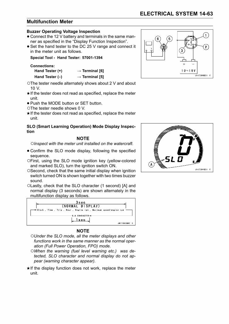
ELECTRICAL SYSTEM 14-63Multifunction Meter
Buzzer Operating Voltage Inspection•Connect the 12 V battery and terminals in the same man-ner as specified in the “Display Function Inspection”.• Set the hand tester to the DC 25 V range and connect itin the meter unit as follows.Special Tool - Hand Tester: 57001-1394
Connections:Hand Tester (+) → Terminal [6]Hand Tester (–) → Terminal [5]
The tester needle alternately shows about 2 V and about10 V.If the tester does not read as specified, replace the meterunit.• Push the MODE button or SET button.The tester needle shows 0 V.If the tester does not read as specified, replace the meterunit.
SLO (Smart Learning Operation) Mode Display Inspec-tion
NOTEInspect with the meter unit installed on the watercraft.•Confirm the SLO mode display, following the specifiedsequence.First, using the SLO mode ignition key (yellow-coloredand marked SLO), turn the ignition switch ON.Second, check that the same initial display when ignitionswitch turned ON is shown together with two times buzzersound.Lastly, check that the SLO character (1 second) [A] andnormal display (3 seconds) are shown alternately in themultifunction display as follows.
NOTEUnder the SLO mode, all the meter displays and otherfunctions work in the same manner as the normal oper-ation (Full Power Operation, FPO) mode.When the warning (fuel level warning etc.) was de-tected, SLO character and normal display do not ap-pear (warning character appear).
If the display function does not work, replace the meterunit.

14-64 ELECTRICAL SYSTEMMultifunction Meter
FPO (Full Power Operation) Mode Display InspectionNOTE
Inspect with the meter unit installed on the watercraft.•Confirm the FPO mode display, following the specifiedsequence.First, using the FPO mode ignition key (orange-colored),turn the ignition switch ON.Second, check that the same initial display when ignitionswitch turned ON is shown together with two times buzzersound.Third, check that the FPO character [A] appear in the mul-tifunction display.Lastly, check that the FPO character disappear and thennormal display appear.
NOTEThe FPO character is shown only once.When the warning (fuel level warning etc.) was de-tected, normal display does not appear (warning char-acter appear).
If the display function does not work, replace the meterunit.

ELECTRICAL SYSTEM 14-65Multifunction Meter
Multifunction Meter Circuit
1. ECU2. Joint Connector 8 (Vcc)3. Joint Connector 7 (Vcc)4. System Relay5. Main (ECU) Relay6. Joint Connector 3 (Switch (12 V))7. Fuel Pump8. Joint Connector 29. Joint Connector 110. Joint Connector 15 (Ground)11. Buzzer12. Multifunction Meter13. Steering Position Sensor14. Joint Connector 1415. Joint Connector 12 (Ground)16. Speed Sensor17. Battery18. Main Fuse 20A

14-66 ELECTRICAL SYSTEMImmobilizer System
This watercraft is equipped with an immobilizer system to protect the watercraft from theft. Thissystem provides a theft proof device by means of matching a code between the inbuilt key transponderand ECU (Electronic Control Unit). If the code does not match, ignition system, injectors and fuel pumpwill not operate and the engine will not start.Abstract• If the LED warning light, immobilizer indicator and the following character blink, and the buzzersound goes off after the key is pressed, this shows a fault in the immobilizer system.Err-Immobilizer Communication TroubleIdA-Immobilizer Amplifier Failure (Service Code: 35)IdEr-Not Matching Key Code (Service Code: 36)
Refer to the service code or character to identity the faulty component.• If all coded keys (FPO key-full power operation mode: orange-colored and SLO key-smart learningoperation mode: yellow-colored and marked SLO) are lost the ECU and ignition switch will have tobe replaced.• The immobilizer system can not function until the user key code is registered in the ECU.• A total of six keys can be registered in the ECU at any one time .Operational Cautions1. Do not expose the keys to excessively high temperature.2. Do not place keys close to magnets.3. Do not place a heavy item on any keys.4. Do not damage the plastic covers.5. Do not give shocks to the keys.6. One registered key is needed to have a new key registered to ECU.7. If both registered keys have been lost, renew the ECU.
NOTESince the immobilizer system uses the electric wave for communication, key identification errormay occur where other electric waves abound.
Key RegistrationCase 1: When the user key has been lost or additionalspare user key is required.•Prepare a new spare user key.•Open the front storage lid and remove the front storagecase.• Disconnect the connector for DIAG and key registration[A].
• Connect the key registration unit [A].Special Tool - Key Registration Unit: 57001-1582

ELECTRICAL SYSTEM 14-67Immobilizer System
Pre-registration of User Key 1• Insert the registered key (user key 1) to the ignition switchand press key [A] during short time (within 2 seconds).
Verified•The ECU confirms the following.Receiving signals from immobilizer amplifier are correct.The user key 1 is registered.• All user key codes in ECU are eliminated.
• The user key 1 is successfully pre-registered in the ECU.The LED warning light [A] blinks 1 time and stops for1 second and then repeats this cycle. Also the buzzersound [B] goes off 1 time.
NOTEOnly the first one cycle, the buzzer sound goes off syn-chronizing with the blink of LED warning light.
Not VerifiedThe LED warning light, immobilizer indicator and char-acter [A] blink to display the collation error. The buzzersound goes off [B]. (refer to the following failure illustra-tions).Immobilizer Amplifier Failure (Service Code/Character-35/Id A)
Key Collation Error (Service Code/Character-36/IdEr)
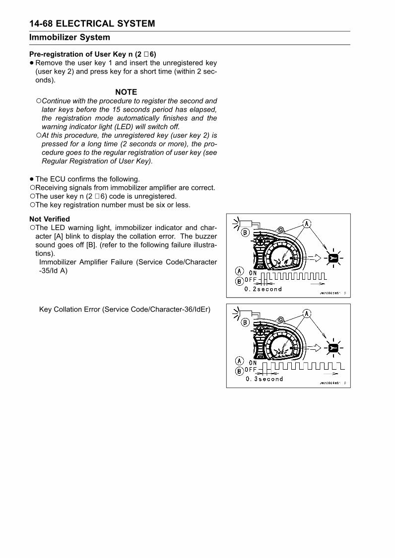
14-68 ELECTRICAL SYSTEMImmobilizer System
Pre-registration of User Key n (2 ∼ 6)•Remove the user key 1 and insert the unregistered key(user key 2) and press key for a short time (within 2 sec-onds).
NOTEContinue with the procedure to register the second andlater keys before the 15 seconds period has elapsed,the registration mode automatically finishes and thewarning indicator light (LED) will switch off.At this procedure, the unregistered key (user key 2) ispressed for a long time (2 seconds or more), the pro-cedure goes to the regular registration of user key (seeRegular Registration of User Key).
•The ECU confirms the following.Receiving signals from immobilizer amplifier are correct.The user key n (2 ∼ 6) code is unregistered.The key registration number must be six or less.Not VerifiedThe LED warning light, immobilizer indicator and char-acter [A] blink to display the collation error. The buzzersound goes off [B]. (refer to the following failure illustra-tions).Immobilizer Amplifier Failure (Service Code/Character-35/Id A)
Key Collation Error (Service Code/Character-36/IdEr)

ELECTRICAL SYSTEM 14-69Immobilizer System
•The user key 2 is successfully pre-registered in the ECU.The LED warning light [A] blinks 2 times and stops for 1second and then repeats this cycle. Also the buzzer [B]sound goes off 2 times.
NOTEOnly the first one cycle, the buzzer sounds goes off syn-chronizing with the blink of LED warning light.
•Continue the procedures to register additional 4 userkeys.
NOTEThe ECU can store up the six key codes (FPO key × nand SLO key × n).
Warning Light Flash and Buzzer Sound
LED WarningLight Blinks andBuzzer Sound
LED WarningLight Blinks andBuzzer Sound
Stop
Remarks
User Key 3 3 times 1 second RepeatUser Key 4 4 times 1 second RepeatUser Key 5 5 times 1 second RepeatUser Key 6 6 times 1 second Repeat
NOTEOnly the first cycle, the buzzer sound goes off synchro-nizing with the blink of LED warning light.
Regular Registration of User Key• Leave the user key (1 ∼ 6) in the ignition switch.• Press key for a long time (2 seconds or more).• The ECU confirms the following.Receiving signals from immobilizer amplifier are correct.The user key is the same as the key pre-registered at theend.
NOTEWhen the user key is not the same with the key pre-registered at the end, registration mode will end instan-taneously. Start the procedure, pre-registration of userkey 1.
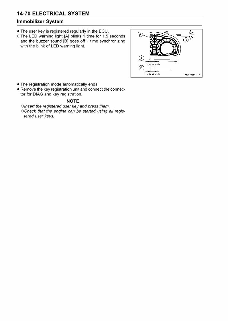
14-70 ELECTRICAL SYSTEMImmobilizer System
•The user key is registered regularly in the ECU.The LED warning light [A] blinks 1 time for 1.5 secondsand the buzzer sound [B] goes off 1 time synchronizingwith the blink of LED warning light.
• The registration mode automatically ends.• Remove the key registration unit and connect the connec-tor for DIAG and key registration.
NOTEInsert the registered user key and press them.Check that the engine can be started using all regis-tered user keys.

ELECTRICAL SYSTEM 14-71Immobilizer System
Spare User Key Registration Flow Chart
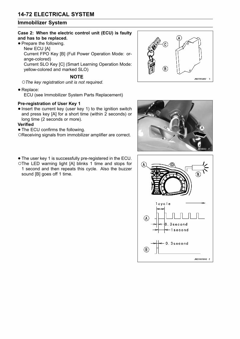
14-72 ELECTRICAL SYSTEMImmobilizer System
Case 2: When the electric control unit (ECU) is faultyand has to be replaced.•Prepare the following.New ECU [A]Current FPO Key [B] (Full Power Operation Mode: or-ange-colored)Current SLO Key [C] (Smart Learning Operation Mode:yellow-colored and marked SLO)
NOTEThe key registration unit is not required.•Replace:ECU (see Immobilizer System Parts Replacement)
Pre-registration of User Key 1• Insert the current key (user key 1) to the ignition switchand press key [A] for a short time (within 2 seconds) orlong time (2 seconds or more).
Verified•The ECU confirms the following.Receiving signals from immobilizer amplifier are correct.
• The user key 1 is successfully pre-registered in the ECU.The LED warning light [A] blinks 1 time and stops for1 second and then repeats this cycle. Also the buzzersound [B] goes off 1 time.

ELECTRICAL SYSTEM 14-73Immobilizer System
Not VerifiedThe LED warning light, immobilizer indicator and char-acter [A] blink to display the collation error. The buzzersound goes off [B]. (refer to the following failure illustra-tions).Immobilizer Amplifier Failure (Service Code/Character-35/Id A)
Key Collation Error (Service Code/Character-36/IdEr)
Pre-registration of User Key 2•Remove the user key 1 and insert the user key 2 andpress key for a short time (within 2 seconds) or long time(2 seconds or more).
NOTEContinue with the procedure to register the first and sec-ond keys before the 15 seconds period has elapsed theregistration mode automatically finishes and the warn-ing indicator light (LED) will switch off.
•The ECU confirms the following.Receiving signals from immobilizer amplifier are correct.Not VerifiedThe LED warning light, immobilizer indicator and charac-ter [A] blinks to display the collation error. The buzzersound goes off [B]. (refer to the following failure illustra-tions).Immobilizer Amplifier Failure (Service Code/Character-35/Id A)

14-74 ELECTRICAL SYSTEMImmobilizer System
Key Collation Error (Service Code/Character-36/IdEr)
• The user key 2 is successfully pre-registered in the ECU.The LED warning light [A] blinks 2 times and stops for 1second and then repeats this cycle. Also the buzzer [B]sound goes off 2 times.
NOTEOnly the first one cycle, the buzzer sounds goes off syn-chronizing with the blink of LED warning light.
Regular Registration of User Key• Leave the user key 2 in the ignition switch.• Press key for a long time (2 seconds or more).• The ECU confirms the following.Receiving signals from immobilizer amplifier are correct.The user key is the same with the user key 2.
NOTEWhen the user key is not the same as the user key 2,registration mode will be end instantaneously. Start theprocedure, pre-registration of user key 1.
•The user key is registered regularly in the ECU.The LED warning light [A] blinks 1 time for 1.5 secondsand the buzzer sound [B] goes off 1 time synchronizingwith the blink of LED warning light.

ELECTRICAL SYSTEM 14-75Immobilizer System
•The registration mode automatically ends.NOTE
Insert the registered user keys and press them.Check that the engine can be started using all regis-tered user keys.
Case 3: When the following both keys are faulty or lost.FPO Key (Full Power Operation Mode: orange-colored)SLO Key (Smart Learning Operation Mode: yel-low-colored and marked SLO)If they are required, the following are necessary.
NOTEThe ECUmust be replaced with a new one because theregistration mode can not start in the state with no key.
•Prepare a new ECU [A], new FPO key [B] and new SLOkeys [C].
NOTEThe key registration unit is not required.The key registration process is same as the electric con-trol unit replacement.
Case 4: When replacing the immobilizer amplifier (igni-tion switch).•Prepare a new immobilizer amplifier (ignition switch).• Refer to the Immobilizer System Parts Replacement.
NOTENo key registration is required.

14-76 ELECTRICAL SYSTEMImmobilizer System
All Keys Initial Registration Flow Chart
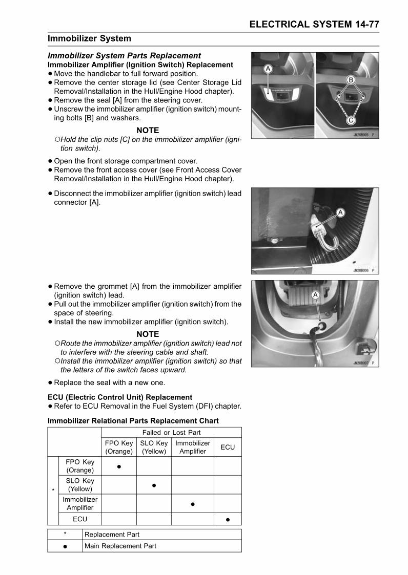
ELECTRICAL SYSTEM 14-77Immobilizer System
Immobilizer System Parts ReplacementImmobilizer Amplifier (Ignition Switch) Replacement•Move the handlebar to full forward position.• Remove the center storage lid (see Center Storage LidRemoval/Installation in the Hull/Engine Hood chapter).• Remove the seal [A] from the steering cover.• Unscrew the immobilizer amplifier (ignition switch) mount-ing bolts [B] and washers.
NOTEHold the clip nuts [C] on the immobilizer amplifier (igni-tion switch).
•Open the front storage compartment cover.• Remove the front access cover (see Front Access CoverRemoval/Installation in the Hull/Engine Hood chapter).
• Disconnect the immobilizer amplifier (ignition switch) leadconnector [A].
• Remove the grommet [A] from the immobilizer amplifier(ignition switch) lead.• Pull out the immobilizer amplifier (ignition switch) from thespace of steering.• Install the new immobilizer amplifier (ignition switch).
NOTERoute the immobilizer amplifier (ignition switch) lead notto interfere with the steering cable and shaft.Install the immobilizer amplifier (ignition switch) so thatthe letters of the switch faces upward.
•Replace the seal with a new one.ECU (Electric Control Unit) Replacement•Refer to ECU Removal in the Fuel System (DFI) chapter.Immobilizer Relational Parts Replacement Chart
Failed or Lost PartFPO Key(Orange)
SLO Key(Yellow)
ImmobilizerAmplifier ECU
FPO Key(Orange) •SLO Key(Yellow) •
ImmobilizerAmplifier •
*
ECU •* Replacement Part
• Main Replacement Part

14-78 ELECTRICAL SYSTEMImmobilizer System
Immobilizer System Inspection•Refer to the Immobilizer Amplifier and Key Collation Er-ror section in Fuel System (DFI) chapter (see ImmobilizerAmplifier and Key Collation Error section in Fuel System(DFI) chapter).
Immobilizer System Circuit
1. ECU2. Joint Connector 8 (Vcc)3. System Relay4. Joint Connector 25. Joint Connector 16. Ignition Switch (Immobilizer Amplifier)7. Joint Connector 15 (Ground)8. Multifunction Meter9. Battery10. Joint Connector 12 (Ground)11. Main Fuse 20 A

ELECTRICAL SYSTEM 14-79Relay Assembly
Relay Assembly Removal•Remove the seat (see Seat Removal in the Hull/EngineHood chapter).• Remove the front access cover (see Front Access CoverRemoval/Installation in the Hull/Engine Hood chapter).• Push in the pins [A] and remove the bracket.• Remove:Relay Assembly Connectors [B]Bolt [C]Main (ECU) Relay [D]Fuel Pump System Relay [E]
Relay Assembly Installation•Apply a non-permanent locking agent to the relay assem-bly mounting bolts and tighten it securely.• Install the bracket with the rivets (see Front Access CoverRemoval/Installation in the Hull/Engine Hood chapter).• Route the relay assembly leads correctly (seeCable, Wireand Harness Routing in Appendix chapter).
Relay Assembly Inspection•Remove the relay assembly.• Check conductivity of the following numbered terminalsby connecting the hand tester and one 12 V battery to therelay assembly as shown.If the tester does not read as specified, replace the relayassembly.

14-80 ELECTRICAL SYSTEMRelay Assembly
Relay Assembly Circuit Inspection (with the battery disconnected)Tester Connection Tester Reading (Ω)
3-4 ∞Main ECU Relay [A]Fuel Pump Relay [A] 1-2 Not ∞*
7-8 ∞System Relay [B]
5-6 Not ∞*(*): The actual reading varies with the hand tester used.
Relay Assembly Circuit Inspection (with the battery connected)Battery Connection
(+) (–)Tester Connection Tester Reading (Ω)
Main (ECU) Relay [A]Fuel Pump Relay [A] 1-2 3-4 0
System Relay [B] 5-6 7-8 0(+): Apply positive lead.(–): Apply negative lead.

ELECTRICAL SYSTEM 14-81Switches
Switch Inspection•Using a hand tester, check to see that only the con-nections shown in the table have continuity (about zeroohms).For the switch housing and the ignition switch, refer to thetables in the Wiring Diagram.If the switch has an open or short, repair it or replace itwith a new one.Special Tool - Hand Tester: 57001-1394
Start Switch
Stop Switch
Tether Switch
Engine Oil Pressure Switch Connections*
*: Engine lubrication system is in good condition
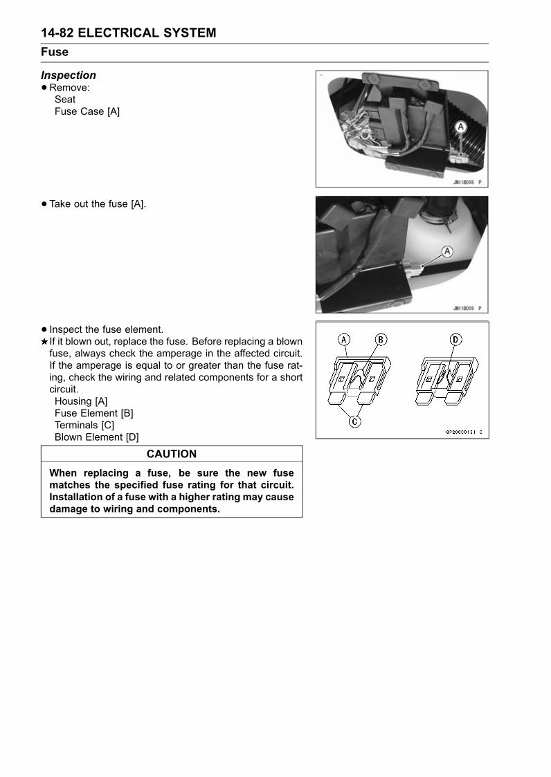
14-82 ELECTRICAL SYSTEMFuse
Inspection•Remove:SeatFuse Case [A]
• Take out the fuse [A].
• Inspect the fuse element.If it blown out, replace the fuse. Before replacing a blownfuse, always check the amperage in the affected circuit.If the amperage is equal to or greater than the fuse rat-ing, check the wiring and related components for a shortcircuit.Housing [A]Fuse Element [B]Terminals [C]Blown Element [D]
CAUTIONWhen replacing a fuse, be sure the new fusematches the specified fuse rating for that circuit.Installation of a fuse with a higher rating may causedamage to wiring and components.

STORAGE 15-1
15
StorageTable of Contents
Preparation for Storage .......................................................................................................... 15-2Cooling System................................................................................................................. 15-2Discharging water in the exhaust system ......................................................................... 15-2Bilge System..................................................................................................................... 15-3Engine Oil ......................................................................................................................... 15-3Fuel System...................................................................................................................... 15-3Engine............................................................................................................................... 15-4Air Filter............................................................................................................................. 15-4Battery............................................................................................................................... 15-5Engine Mounting Bolts ...................................................................................................... 15-5Lubrication ........................................................................................................................ 15-5General ............................................................................................................................. 15-5
Removal from Storage............................................................................................................ 15-6Lubrication ........................................................................................................................ 15-6General Inspection............................................................................................................ 15-6Fuel System...................................................................................................................... 15-6Test Run............................................................................................................................ 15-7

15-2 STORAGEPreparation for Storage
During the winter, or whenever the watercraft will not bein use for a long period of time, proper storage is essential.It consists of checking and replacing missing or worn parts;lubricating parts to ensure that they do not become rusted;and, in general, preparing the watercraft so that when thetime comes to use it again, it will be in top condition.
NOTEPersonal watercraft is not meant to be left in the waterfor extended periods. Continuous exposure to waterover a long period of time will cause the hull paint tobubble and peel. It also causes electrolytic erosion ofthe metal parts of the pump, decreasing its service life.Larger boats which are left in the water must be hauledout periodically, so the bottom of the hull can be scrapedand repainted with anti-fouling paint. They also usuallyhave a sacrificial anode to reduce electrolytic erosion ofmetal parts in contact with the water.
Cooling System•Clean the cooling system (see Cooling System Flushingin the Periodic Maintenance chapter).•When storing the watercraft in an area where the temper-ature drops below freezing, perform the following.
Discharging water in the exhaust systemCAUTION
Discharge water from the exhaust system afterflushing the cooling system.Water remaining in the exhaust system during coldweather could freeze and damage the exhaust pipe.
•After flushing, remove the cooling water hose [C] fromthe fitting [B] on the engine output cover [A] at the rearof the engine. Lead the hose to the lowest level in theengine room so that water remaining in the exhaust pipe[D] drains out.Air Filter Box [E]• Connect the hose to fitting on the output cover and tightenthe clamp securely.
CAUTIONConnect the hose securely to the fitting.If the hose comes off during operation, cooling wa-ter could swamp the boat.If you are not confident you can perform storageprocedures, ask your Kawasaki JET SKI watercraftdealer for this service.

STORAGE 15-3Preparation for Storage
Bilge System•Clean the bilge system (see the Periodic Maintenancechapter). Before reconnecting the hoses to the plasticbreather fitting, blow air through both hoses [A] to forceall water out of the bilge system.
Engine Oil•Change the engine oil (see Engine Lubrication System inPeriodic Maintenance chapter).
Fuel SystemWARNING
Gasoline is extremely flammable and can be explo-sive under certain conditions. Pull the lanyard keyoff the stop button. Do not smoke. Make sure thearea is well ventilated and free from any source offlame or sparks; this includes any appliance with apilot light.
•Drain the fuel tank. This should be done with a siphon orpump.[A] Siphon Hose
NOTELift the stern upward a little so that fuel and water in thebottom of the fuel tank may flow toward the fuel filter tocompletely drain the fuel tank.
•Remove the fuel pump (see the Fuel System chapter).• Clean the fuel pump screen [A] (see Fuel System in Pe-riodic Maintenance chapter).• Refill the fuel tank with fresh fuel approximately 10 L (2.6gal U.S.).• Turn the ignition switch on.• Push the lanyard key under the stop button, and start theengine and run it in 15 second periods until all fuel in thefuel system is with fresh fuel. Wait 5 minutes between 15seconds running periods.
CAUTIONDo not run the engine without cooling water supplyfor more than 15 seconds at a time or severe engineand exhaust system damage will occur.
•Pull the lanyard key off the stop button and turn the igni-tion switch off.• Drain the fuel tank.• Leave the fuel filler cap loose to prevent condensation inthe tank.

15-4 STORAGEPreparation for Storage
Engine•Remove the front storage pocket (see Hull/Engine Hoodchapter).• Disconnect both two connection on the ignition coil pri-mary lead connectors [A].• Remove the spark plugs (see Electrical System in Peri-odic Maintenance chapter).• Spray fogging oil directly into each cylinder.• Turn the ignition switch on.• Push the lanyard key under the stop button. Turn theengine over several times with the start button to coat thecylinder walls with oil.
WARNINGDo not lean over the engine when performing thisprocedure. An air/oil mist may be forcibly ejectedfrom the spark plug holes and could get into youreyes. If you do get some in your eyes, wash youreyes immediately with liberal amounts of clean,fresh water. Consult a physician as soon as pos-sible.
•Pull the lanyard key off the stop button and turn the igni-tion switch off.• Spray the spark plugs with fogging oil, and reinstall thespark plugs and caps (see Electrical System in PeriodicMaintenance chapter).
• Reconnect the primary ignition coil lead connectors, not-ing the #1,#4 [A] and the #2, #3 [B] coil connectors. The#1, #4 coil connector has a red/yellow and a green/blueleads from the main harness. The #2, #3 coil connec-tor has a red/yellow and green/black leads from the mainharness.
NOTEThe service codes (COIL1 and COIL2) caused by thisprocedure are stored in the ECU. If necessary, theseservice codes can be erased by using the KawasakiDiagnostic System (KDS).
Air Filter•Remove the air filter (see Fuel (DFI) System chapter).• Disassemble the air filter (see Fuel (DFI) System chap-ter).•Wash and dry the flame arrester [A].• Assemble and install the air filter (see Fuel (DFI) Systemchapter).

STORAGE 15-5Preparation for Storage
Battery•Give a refresh charge before you store the watercraft andstore it with the negative lead removed. Give a refreshcharge once a month during storage.• Remove the battery (see Electrical System in PeriodicMaintenance chapter).• Clean the exterior with a solution of baking soda and wa-ter (one heaping tablespoon of baking soda in one cup ofwater). Rinse thoroughly with water.
CAUTIONDo not allow any soda solution to enter the battery.
•Coat both battery terminals with grease.• Store the battery in a cool, dry place. Do not expose it tofreezing temperatures.
Engine Mounting Bolts•Torque all engine mounting bolts (see Engine Re-moval/Installation chapter).Torque - EngineMounting Bolts: 36 N·m (3.7 kgf·m, 27 ft·lb)
Lubrication•Carry out all recommended lubrication procedures (seeLubrication in Periodic Maintenance chapter).
General•Wash the engine compartment with fresh water and re-move the drain screw in the stern to drain the water. Wipeup any water left in the compartment.
CAUTIONUse only a mild detergent in water to wash the hull.Harsh solvents may attack the surface or smear thecolors.
•Apply a good grade of wax to all exterior hull surfaces.• Lightly spray all exposed metal parts with a penetratingrust inhibitor.• Remove the seat, or block the seat up with 10 mm (0.39in.) spacers to insure adequate ventilation, and preventcorrosion.• Cover the watercraft and store it in a clean, dry place.
15-6 STORAGERemoval from Storage
Lubrication•Carry out all recommended lubrication procedures (seethe Periodic Maintenance chapter).
General Inspection•Check for binding or sticking throttle, steering or shiftmechanism. The throttle lever must return fully whenreleased.• Clean and gap spark plugs (see Electrical System in Pe-riodic Maintenance chapter).• Check all rubber hoses for weathering a cracking, orlooseness.• Check that the drain screw in the stern is securely tight-ened.• Check the fire extinguisher for a full charge.• Check the battery, charge if necessary, and clean the ter-minals. Install the battery (see Battery Installation in Elec-trical System chapter).
Fuel System•Check and clean or replace the fuel pump screens as nec-essary (see Fuel System in Periodic Maintenance chap-ter).
WARNINGGasoline is extremely flammable and can be explo-sive under certain conditions. Pull the lanyard keyoff the stop button. Do not smoke. Make sure thearea is well ventilated and free from source of flameor spark; this includes any appliance with a pilotlight.
•After refueling and before starting the engine, tilt the seatto the rear for several minutes to ventilate the engine com-partment.
WARNINGA concentration of gasoline fumes in the enginecompartment can cause a fire or explosion.
•Check for fuel leaks. Repair if necessary.• Check the engine oil level. Fill the oil with the specifiedoil.

STORAGE 15-7Removal from Storage
Test RunWARNING
Do not run the engine in a closed area. Exhaustgases contain carbon monoxide, a colorless, odor-less, poisonous gas. Breathing exhaust gas leadsto carbon monoxide poisoning, asphyxiation, anddeath.
•Start the engine and run it only for 15 seconds. Check forfuel, oil and exhaust leaks. Any leaks must be repaired.
CAUTIONDo not run the engine without cooling water supplyfor more than 15 seconds at a time or severe engineand exhaust system damage will occur.
• Install the seat making sure it is locked.


APPENDIX 16-1
16
AppendixTable of Contents
Cable, Wire and Hose Routing............................................................................................... 16-2Troubleshooting Guide ........................................................................................................... 16-28

16-2 APPENDIXCable, Wire and Hose Routing

APPENDIX 16-3Cable, Wire and Hose Routing
1. Flushing Cap2. Cylinder Head Cover3. Throttle Cable4. Delivery Pipe5. Fix the throttle cable to the delivery pipe with the band.6. Inlet Manifold7. Horizontal Plane8. Position the clamp pinch head below the horizontal plane.9. Throttle Body Assy10. Air Filter11. Clamp12. Cooling Hose (Cylinder ∼ Left Water Box Muffler)13. Oil Pan14. Position the clamp pinch head as shown.15. Oil Separator Tank Hose (Tank ∼ Oil Pan)16. Cooling Hose (Pump ∼ Output Cover)17. Output Cover18. Exhaust Pipe19. Cooling Hose (Output Cover ∼ Exhaust Pipe)20. Band21. Oil Separator Tank22. Cooling Hose (Left Water Box Muffler ∼ Cylinder)23. Return Oil Hose (Cylinder ∼ Oil Pan)24. Air Filter Drain Cap25. White Mark26. Oil Separator Tank Hose (Tank ∼ Air Filter)27. Deck (Port Side)28. Oil Separator Tank Hose (Cylinder Head Cover ∼ Tank)29. Plate30. Air Suction Valve Hose31. Exhaust Manifold32. Flushing Hose33. Bypass Outlet Hose34. Breather Hose (Cylinder Head ∼ Breather Case)35. Run the hose to front of fuel pump (JT1500C8F).

16-4 APPENDIXCable, Wire and Hose Routing

APPENDIX 16-5Cable, Wire and Hose Routing
1. Oil Cooler2. Cylinder Head3. Water Pipe4. Cylinder5. Oil Filter6. Oil Pan7. Battery (−) Cable8. Starter Motor9. Starter Motor Cable10. Cooling Hose (Cylinder Head ∼ Left Water Box Muffler)11. Band12. Output Cover13. Water Hose Joint (Inlet)14. Water Hose joint (Outlet)15. Return Oil Hose (Cylinder ∼ Oil Pan)16. Protective Tube

16-6 APPENDIXCable, Wire and Hose Routing

APPENDIX 16-7Cable, Wire and Hose Routing
1. Clamp2. Breather Hose (Cylinder Head ∼ Breather Case)3. Clamp Detail4. Position the clamp pinch heads as shown.5. Air Suction Valve6. Air Suction Valve Hose7. Inlet Water Pipe Joint on the Cylinder (Cooling Water from Left Water Box Muffler)8. Cylinder9. Cylinder Head Cover10. Output Cover11. Protective Tube12. Return Oil Hose (Cylinder ∼ Oil Pan)13. Breather Hose (Cylinder ∼ Breather Case)14. Breather Case15. Oil Pan16. Front Pinch Head17. Rear Pinch Head18. Position the clamp so that its pinch heads do not touch the oil separator tank hose.

16-8 APPENDIXCable, Wire and Hose Routing
APPENDIX 16-9Cable, Wire and Hose Routing
Refer to the Exploded View and Flow Diagram in the Cooling and Bilge Systems chapter.Install the clamp as shown, noting its screw head direction.1. Bypass Outlet2. Clamp3. Holder4. Bypass Outlet Hose5. Cooling Hose6. Cooling Hose (Pump ∼ Oil Cooler)7. Oil Cooler8. Water Pipe on the Cylinder Head9. Position the clamp screw head as shown.10. Cooling Hose (Cylinder Head ∼ Water Pipe Joint under the Left Water Box Muffler)11. Protective Tube12. Cooling Hose (Output Cover ∼ Exhaust Pipe)13. Output Cover14. Cooling Hose (Pump ∼ Output Cover)15. Oil Pan16. Band17. Position the clamp so that its screw head faces downward and outside.18. Pump19. Drain20. Cooling Hose (Pump ∼ Output Cover)21. Left Water Box Muffler22. Cooling Hose (Left Water Box Muffler ∼ Hull)23. Fix the No.24 and No.25 cooling hoses with the band.24. Cooling Hose (Output Cover ∼ Exhaust Pipe)25. Cooling hose (left water box muffler ∼ cylinder): Run the No.25 cooling hose under the No.24
cooling hose as shown.26. Exhaust Pipe27. Position the clamp so that its screw head faces inside.28. Exhaust Manifold29. Cooling Hose (Oil Cooler ∼ Exhaust Manifold)30. Steering Cable31. Fix the No. 6 cooling hose and the steering cable with the band.32. Run the hose to front of fuel pump.33. JT1500C8F

16-10 APPENDIXCable, Wire and Hose Routing

APPENDIX 16-11Cable, Wire and Hose Routing
1. Flushing Cap2. Clamp3. Right Side Cover4. Flushing Line

16-12 APPENDIXCable, Wire and Hose Routing

APPENDIX 16-13Cable, Wire and Hose Routing
1. Exhaust Manifold2. Exhaust Pipe3. Water Hose Point (Cooling Hose from the Output Cover)4. 30°5. Water Hose Joint (Cooling Hose from the Oil Cooler)6. Upper Water Hose Joint7. Cooling Hose Fitting (Left Water Box Muffler ∼ Cylinder)8. Cooling Hose Fitting (Left Water Box Muffler ∼ Drain)9. Lower Water Hose Joint10. 45°11. Dampers12. Left Water Box Muffler13. Position the clamp so that their screw heads face forward.14. To Tail Pipe15. Arrow Marks16. Exhaust Tubes17. Right Water Box Muffler18. 30°19. JT1500C8F

16-14 APPENDIXCable, Wire and Hose Routing

APPENDIX 16-15Cable, Wire and Hose Routing
1. Right Rear Duct2. Right Bilge Hose3. Left Bilge Hose4. Left Rear Duct5. Left Water Box Muffler6. Right Water Box Muffler7. Right Bilge Breather8. Left Bilge Breather9. Left Bilge Filter10. Right Bilge Filter11. Left Front Duct12. Right Front Duct13. Band14. 150 mm (5.91 in.)
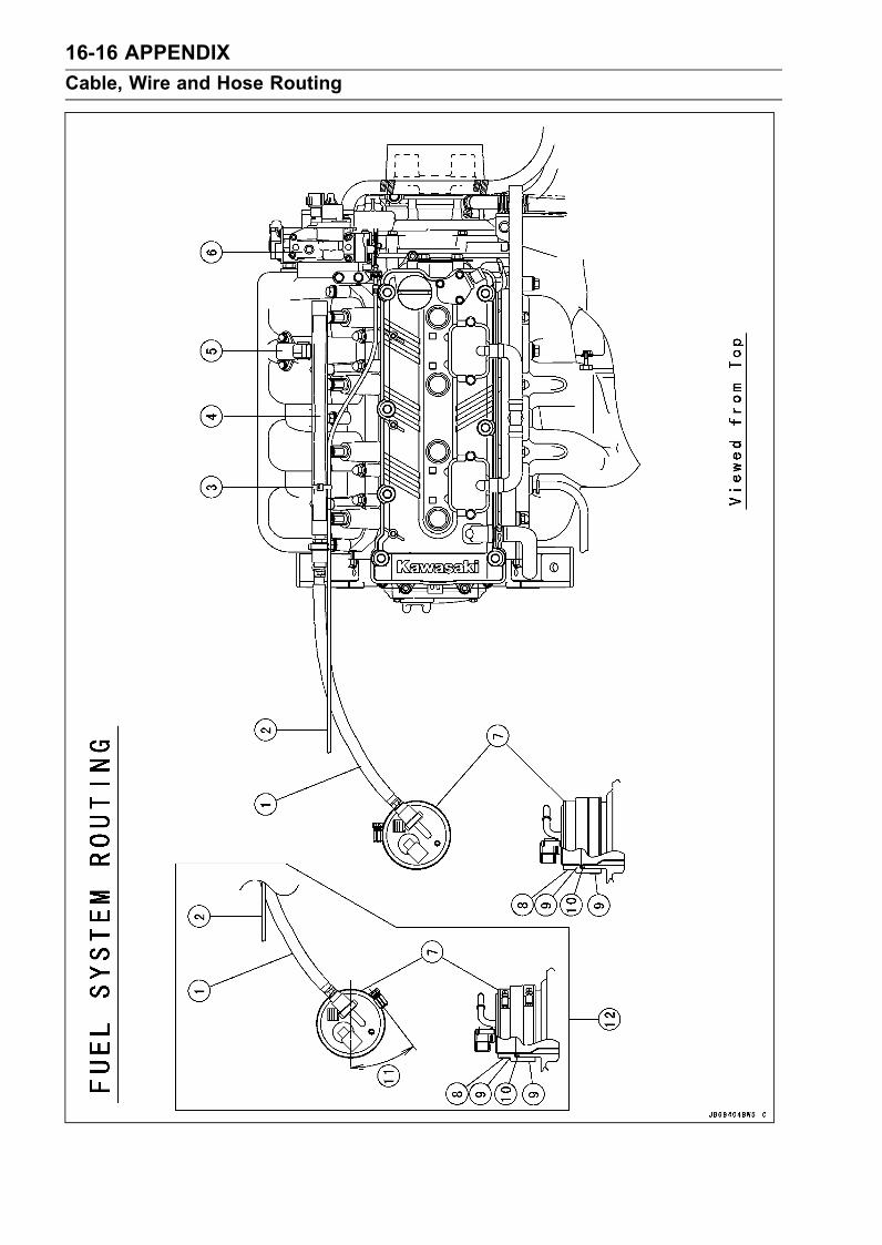
16-16 APPENDIXCable, Wire and Hose Routing
APPENDIX 16-17Cable, Wire and Hose Routing
1. Fuel Hose2. Throttle Cable3. Clamp4. Delivery Pipe5. Inlet Air Pressure Sensor6. Throttle Body7. Fuel Pump8. Clamp9. Holder10. O-ring11. 40°12. JT1500C8F
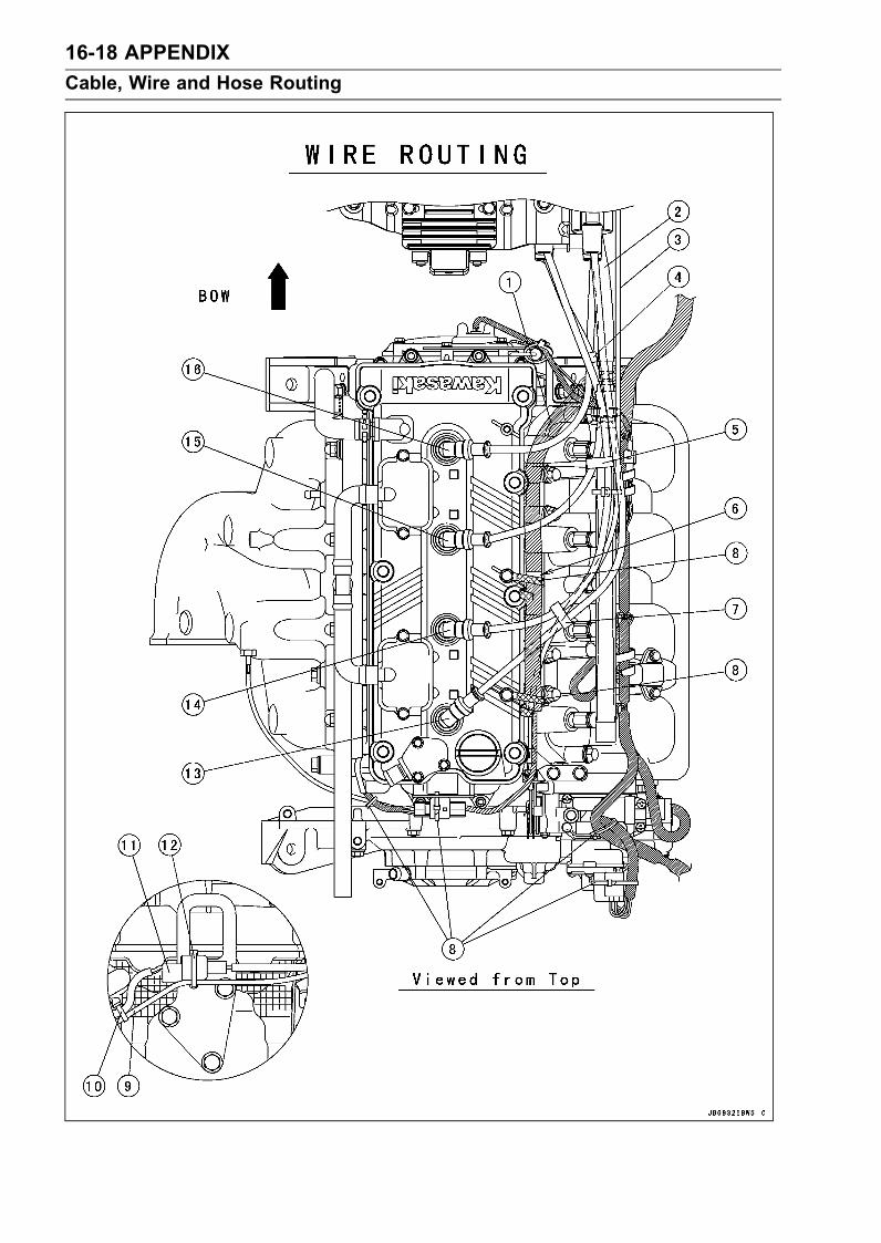
16-18 APPENDIXCable, Wire and Hose Routing
APPENDIX 16-19Cable, Wire and Hose Routing
1. Run the harness under the throttle cable and the fuel hose.2. Fuel Hose3. Throttle Cable4. Fix the #1 and #2 spark plug leads with the clamp.5. Fix the #2 and #3 spark plug leads with the clamp.6. Position the white tape with the boss.7. Fix the #3 and #4 spark plug leads with the clamp.8. Clamps9. Water Temperature Sensor Leads10. Clamp the water temperature sensor and camshaft position sensor leads.11. Camshaft Position Sensor Connector12. Fix the camshaft position sensor connector and water temperature sensor leads with the band.13. #4 Spark Plug Lead14. #3 Spark Plug Lead15. #2 Spark Plug Lead16. #1 Spark Plug Lead

16-20 APPENDIXCable, Wire and Hose Routing

APPENDIX 16-21Cable, Wire and Hose Routing
1. Crankshaft Sensor Leads2. Grommet3. Crankshaft Sensor Cover (Reverse Side)4. Crankshaft Sensor5. Magneto Cover (Reverse Side)6. Magneto Leads7. Plate for fixing the magneto leads: Do not place the leads between the plate and magneto cover.8. Run the magneto leads along the hollow of the magneto cover.9. Crankcase10. Coupling11. Output Cover12. Run the magneto leads between the magneto cover and output cover. Do not pinch the leads.

16-22 APPENDIXCable, Wire and Hose Routing
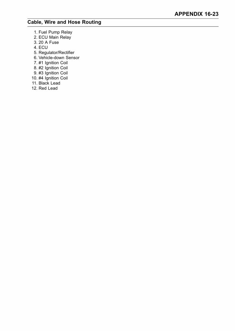
APPENDIX 16-23Cable, Wire and Hose Routing
1. Fuel Pump Relay2. ECU Main Relay3. 20 A Fuse4. ECU5. Regulator/Rectifier6. Vehicle-down Sensor7. #1 Ignition Coil8. #2 Ignition Coil9. #3 Ignition Coil10. #4 Ignition Coil11. Black Lead12. Red Lead

16-24 APPENDIXCable, Wire and Hose Routing

APPENDIX 16-25Cable, Wire and Hose Routing
1. Battery (–) Cable2. Baatery (–) Lead3. Connector for DIAG and Key Resistration4. Starter Relay5. Red Mark6. battery (+) Cable7. To Starter Motor8. Starter Relay Leads9. Battery (+) Lead10. Battery

16-26 APPENDIXCable, Wire and Hose Routing

APPENDIX 16-27Cable, Wire and Hose Routing
1. Fuel Vent Hose2. Start/Stop Switch Leads3. multifunction Leads4. Grommet5. Throttle Cable6. Buzzer Leads7. Clamp8. Protect Tube9. Handlebar Pad10. Buzzer Leads11. Steering Shaft12. Steering Position Sensor

16-28 APPENDIXTroubleshooting Guide
NOTEThis is not an exhaustive list, giving every possible cause for each problem listed. It is meantsimply as a rough guide to assist the troubleshooting for some of the more common difficulties.
Engine Doesn’t Start, Starting DifficultyStarter motor not rotatingStarter motor trouble (brushes worn)Battery voltage lowStarter relay not contacting or operatingStart button not contactingWiring open or shortedIgnition switch troubleEngine stop switch troubleFuse blownImmobilizer system trouble
Starter motor rotating but engine doesn’t turn overReduction gear troubleVehicle-down sensor (DFI) coming off
Engine won’t turn overValve seizureValve lifter seizureCylinder, piston seizureCrankshaft seizureConnecting rod small end seizureConnecting rod big end seizureCamshaft seizure
No fuel flowNo fuel in tankFuel tank air vent obstructedFuel pump screen and/or fuel filter cloggedFuel injector troubleFuel line clogged
Engine floodedClean spark plug and adjust plug gapStarting technique faulty (When flooded, do not crank the engine with the throttle fully opened.This promotes engine flood because more fuel is supplied automatically by DFI.)
No spark; spark weakIgnition coil faultyVehicle-down sensor (DFI) coming offVehicle-down sensor troubleIgnition switch turned OFF and/or lanyard key not pushed under stop buttonBattery voltage lowSpark plug dirty, broken, or gap maladjustedIgnition coil shorted or not in good contactIgnition coil troubleSpark plug incorrectSpark plug cap troubleSpark plug cap shorted or not in good contactIC igniter in ECU troubleCamshaft position sensor troubleCrankshaft sensor troubleWiring shorted or openFuse blown
Fuel/air mixture incorrectAir passage cloggedAir filter poorly sealedFuel injector trouble

APPENDIX 16-29Troubleshooting Guide
Water or foreign matter in fuelThrottle sensor troubleFuel pressure may be lowFuel pump troubleInlet air pressure sensor troubleInlet air temperature sensor troubleWater temperature sensor troubleCrankshaft sensor trouble
Compression LowSpark plug looseCylinder head not sufficiently tightened downNo valve clearanceCylinder, piston wornPiston ring bad (worn, weak, broken, or sticking)Piston ring/groove clearance excessiveCylinder head gasket damagedCylinder head warpedValve spring broken or weakValve not seating properly (valve bent, worn, or carbon accumulation on the seating surface)
Poor Running at Low SpeedSpark weakBattery voltage lowSpark plug dirty, broken, or maladjustedIgnition coil shorted or not in good contactIgnition coil troubleSpark plug incorrectSpark plug cap troubleSpark plug cap shorted or not in good contactIC igniter in ECU troubleCamshaft position sensor troubleCrankshaft sensor trouble
Fuel/air mixture incorrectAir passage cloggedAir filter poorly sealedFuel tank air vent obstructedFuel pump troubleInlet air duct looseFuel pump screen and/or fuel filter cloggedThrottle body assy looseThrottle body assy gasket damageFuel line cloggedInlet air pressure sensor troubleInlet air temperature sensor trouble
Engine stalls easilyFuel pump troubleFuel injector troubleThrottle sensor troubleCamshaft position sensor troubleFuel pressure too low or too highInlet air pressure sensor troubleWater temperature sensor troubleInlet air temperature sensor troubleFuel line cloggedCrankshaft sensor troubleIgnition coil trouble
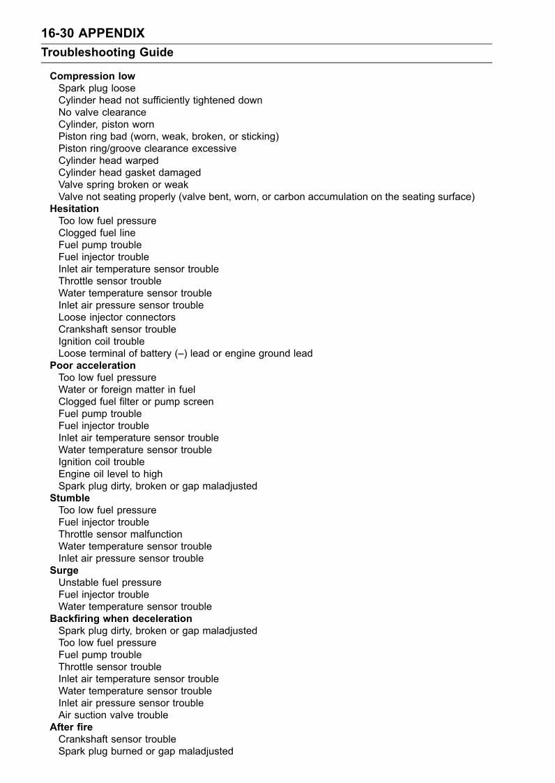
16-30 APPENDIXTroubleshooting Guide
Compression lowSpark plug looseCylinder head not sufficiently tightened downNo valve clearanceCylinder, piston wornPiston ring bad (worn, weak, broken, or sticking)Piston ring/groove clearance excessiveCylinder head warpedCylinder head gasket damagedValve spring broken or weakValve not seating properly (valve bent, worn, or carbon accumulation on the seating surface)
HesitationToo low fuel pressureClogged fuel lineFuel pump troubleFuel injector troubleInlet air temperature sensor troubleThrottle sensor troubleWater temperature sensor troubleInlet air pressure sensor troubleLoose injector connectorsCrankshaft sensor troubleIgnition coil troubleLoose terminal of battery (–) lead or engine ground lead
Poor accelerationToo low fuel pressureWater or foreign matter in fuelClogged fuel filter or pump screenFuel pump troubleFuel injector troubleInlet air temperature sensor troubleWater temperature sensor troubleIgnition coil troubleEngine oil level to highSpark plug dirty, broken or gap maladjusted
StumbleToo low fuel pressureFuel injector troubleThrottle sensor malfunctionWater temperature sensor troubleInlet air pressure sensor trouble
SurgeUnstable fuel pressureFuel injector troubleWater temperature sensor trouble
Backfiring when decelerationSpark plug dirty, broken or gap maladjustedToo low fuel pressureFuel pump troubleThrottle sensor troubleInlet air temperature sensor troubleWater temperature sensor troubleInlet air pressure sensor troubleAir suction valve trouble
After fireCrankshaft sensor troubleSpark plug burned or gap maladjusted
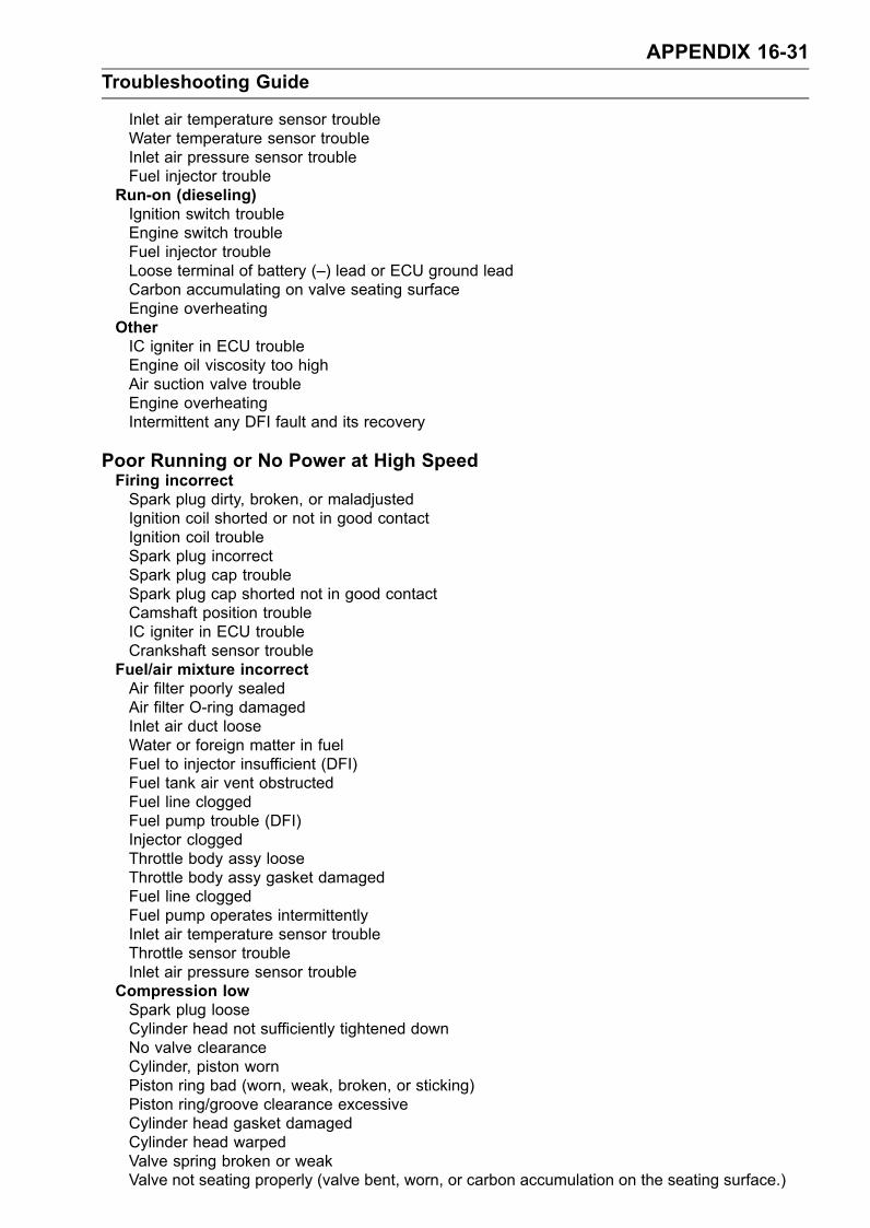
APPENDIX 16-31Troubleshooting Guide
Inlet air temperature sensor troubleWater temperature sensor troubleInlet air pressure sensor troubleFuel injector trouble
Run-on (dieseling)Ignition switch troubleEngine switch troubleFuel injector troubleLoose terminal of battery (–) lead or ECU ground leadCarbon accumulating on valve seating surfaceEngine overheating
OtherIC igniter in ECU troubleEngine oil viscosity too highAir suction valve troubleEngine overheatingIntermittent any DFI fault and its recovery
Poor Running or No Power at High SpeedFiring incorrectSpark plug dirty, broken, or maladjustedIgnition coil shorted or not in good contactIgnition coil troubleSpark plug incorrectSpark plug cap troubleSpark plug cap shorted not in good contactCamshaft position troubleIC igniter in ECU troubleCrankshaft sensor trouble
Fuel/air mixture incorrectAir filter poorly sealedAir filter O-ring damagedInlet air duct looseWater or foreign matter in fuelFuel to injector insufficient (DFI)Fuel tank air vent obstructedFuel line cloggedFuel pump trouble (DFI)Injector cloggedThrottle body assy looseThrottle body assy gasket damagedFuel line cloggedFuel pump operates intermittentlyInlet air temperature sensor troubleThrottle sensor troubleInlet air pressure sensor trouble
Compression lowSpark plug looseCylinder head not sufficiently tightened downNo valve clearanceCylinder, piston wornPiston ring bad (worn, weak, broken, or sticking)Piston ring/groove clearance excessiveCylinder head gasket damagedCylinder head warpedValve spring broken or weakValve not seating properly (valve bent, worn, or carbon accumulation on the seating surface.)

16-32 APPENDIXTroubleshooting Guide
KnockingCarbon built up in combustion chamberFuel poor quality or incorrectSpark plug incorrectIC igniter in ECU troubleCamshaft position sensor troubleCrankshaft sensor troubleIgnition coil troubleInlet air temperature sensor trouble
MiscellaneousThrottle valve won’t fully openEngine overheatingEngine oil level too highEngine oil viscosity too highAir suction valve troubleCamshaft cam worn
OverheatingFiring incorrectSpark plug dirty, broken, or maladjustedSpark plug incorrectIC igniter in ECU trouble
Fuel/air mixture incorrectInlet air duct looseAir filter poorly sealedAir filter O-ring damaged
Compression highCarbon built up in combustion chamber
Engine load faultyEngine oil level too highEngine oil viscosity too high
Lubrication inadequateEngine oil level too lowEngine oil poor quality or incorrect
Oil cooler incorrectOil cooler clogged
Sensor incorrectWater temperature sensor broken
Over CoolingSensor incorrectWater temperature sensor broken
Abnormal Engine NoiseKnockingIC igniter in ECU troubleCarbon built up in combustion chamberFuel poor quality or incorrectSpark plug incorrectOverheating
Piston slapCylinder/piston clearance excessiveCylinder, piston wornConnecting rod bentPiston pin, piston pin hole worn

APPENDIX 16-33Troubleshooting Guide
Valve noiseValve clearance incorrectValve spring broken or weakCamshaft bearing wornValve lifter worn
Other noiseConnecting rod small end clearance excessiveConnecting rod big end clearance excessivePiston ring/groove clearance excessivePiston ring worn, broken, or stuckPiston ring groove wornPiston seizure, damageCylinder head gasket leakingCrankshaft runout excessiveEngine mount looseCrankshaft bearing wornCamshaft chain tensioner troubleCamshaft chain, sprocket, guide wornAir suction valve damagedMagneto flywheel loose
Oil Pressure Warning Light Goes OnOil pump damagedOil screen cloggedOil filter cloggedEngine oil level too lowEngine oil viscosity too lowCamshaft bearing wornCrankshaft bearing wornOil pressure switch damagedWiring faultyO-ring at the oil passage in the crankcase damaged
Battery TroubleBattery dischargedCharge insufficientBattery faulty (too low terminal voltage)Battery lead making poor contactMagneto troubleWiring faultyRegulator/rectifier trouble
Battery overchargedMagneto troubleRegulator/rectifier troubleBattery faulty
Poor Performance through Engine Runs ProperlyJet pumpIntake area obstructedImpeller or pump case damagedExcessive clearance between impeller and pump case
Poor Steering Control (Since faulty steering is dangerous, this problem shouldbe examined by an authorized Jet Ski dealer)Handlebar hard to turnSteering maladjusted

16-34 APPENDIXTroubleshooting Guide
Bushing damaged or crackedSteering shaft bentNo lubricant on steering pivotSteering cable damaged or improperly routed
Engine Activates Slow Down ModeCooling water temperature gets highWeeds or debris in jet pumpCooling water line clogged
Low oil pressureLow oil levelImproper engine oil quality
Water temperature sensors malfunction, wiring open or shortVehicle-down sensor malfunction, wiring open or shortOil temperature sensor gets highLow oil levelOil pump malfunctionRelief valve malfunctionWeeds or debris in jet pumpCooling water line clogged
Oil temperature sensor malfunction, wiring open or short

MODEL APPLICATIONYear Model Beginning Hull No.2007 JT1500C7F US-KAW400016072008 JT1500C8F US-KAW50001708
:This digit in the hull number changes from one machine to another.
Part No.99924-1376-02 Printed in Japan