Embed Size (px)
Citation preview
MULTI-SHOT PNEUMATIC AIR RIFLE
Jäger evo
OPERATION MANUAL
Attention! For your own and other people’s safety you should carefully study this operation manual
(hereinafter OM) before beginning of operation. Depending on its version, the rifle Jäger (Jaeger) in compliance with the
air weapons classification as per GOST R 51612-2000 is referred to: 1. Cal.5.5 SPR – to items structurally similar to air weapons of 5.5 mm
caliber with a muzzle energy from 0.5 to 3 J. 2. Cal.5.5 XPR – to hunting air weapons of 5.5 mm caliber with a muz-
zle energy from 7.5 to 25 J. 3. Cal.4.5 МPR – to air weapons for hobby and sport of 4.5 mm caliber
with a muzzle energy up to 7.5 J. 4. Cal.4.5 МP – to air weapons for hobby and sport of 4.5 mm caliber
with a muzzle energy up to 7.5 J. 5. Cal.5.5 SP - to items structurally similar to air weapons of 5.5 mm
caliber with a muzzle energy from 0.5 to 3 J. 6. Cal.5.5 XP - to hunting air weapons of 5.5 mm caliber with a muzzle
energy from 7.5 to 25 J. 7. Cal.6.35 SPR - to items structurally similar to air weapons of 6.35
mm caliber with a muzzle energy from 0.5 to 3 J. 8. Cal.6.35 XPR - to hunting air weapons of 6.35 mm caliber with a
muzzle energy from 7.5 to 25 J. 9. Cal.6.35 SP - to items structurally similar to air weapons of 6.35 mm
caliber with a muzzle energy from 0.5 to 3 J. 10. Cal.6.35 XP - to hunting air weapons of 6.35 mm caliber with a muz-
zle energy from 7.5 to 25 J. 11. Cal. .30 XP - to hunting air weapons of 7.62 mm caliber with a muz-
zle energy from 7.5 to 25 J. 12. Cal. .30 XPR - to hunting air weapons of 7.62 mm caliber with a
muzzle energy from 7.5 to 25 J. 13. Cal. .35 XP - to hunting air weapons of 7.62 mm caliber with a muz-
zle energy from 7.5 to 25 J. 14. Cal. .35 XPR - to hunting air weapons of 7.62 mm caliber with a
muzzle energy from 7.5 to 25 J.
2
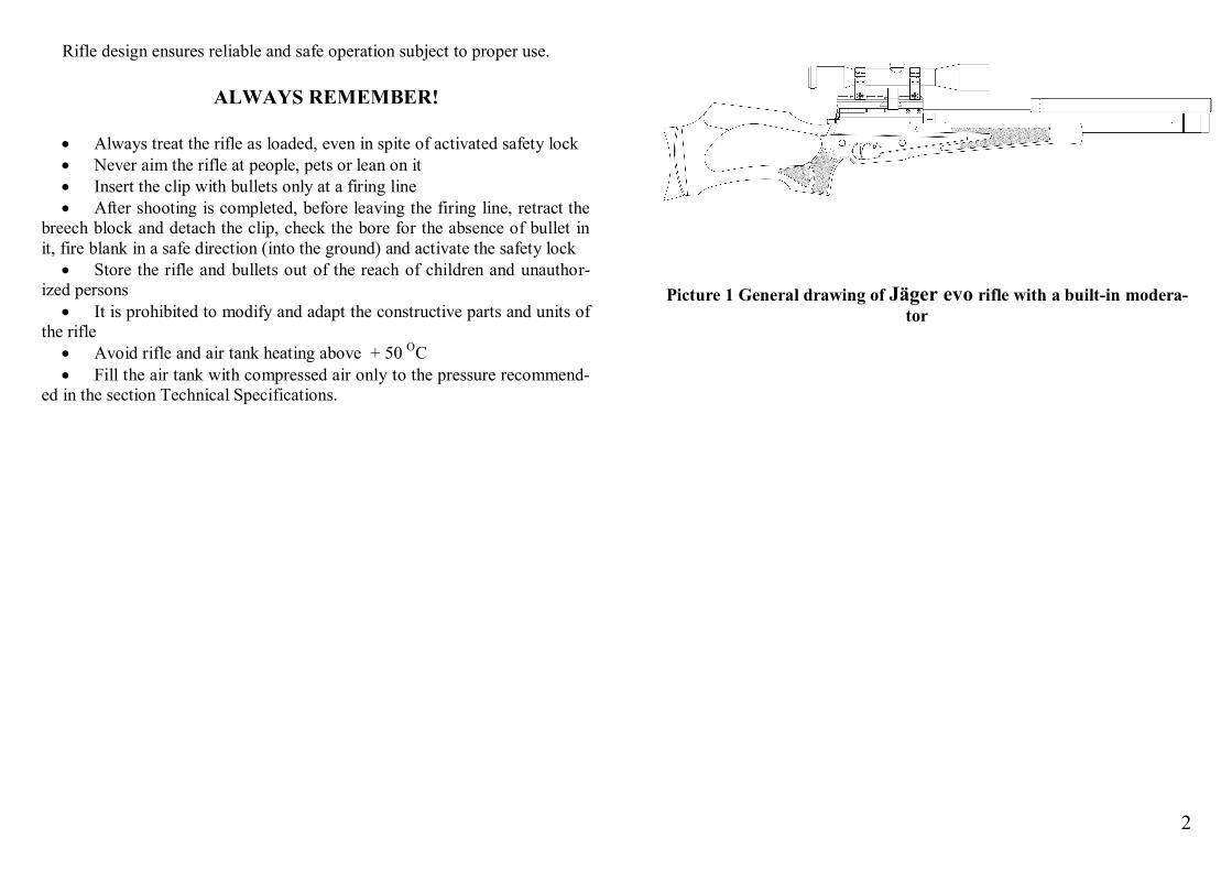
Rifle design ensures reliable and safe operation subject to proper use.
ALWAYS REMEMBER! Always treat the rifle as loaded, even in spite of activated safety lock Never aim the rifle at people, pets or lean on it Insert the clip with bullets only at a firing line After shooting is completed, before leaving the firing line, retract the
breech block and detach the clip, check the bore for the absence of bullet in it, fire blank in a safe direction (into the ground) and activate the safety lock
Store the rifle and bullets out of the reach of children and unauthor-ized persons
It is prohibited to modify and adapt the constructive parts and units of the rifle
Avoid rifle and air tank heating above + 50 С Fill the air tank with compressed air only to the pressure recommend-
ed in the section Technical Specifications.
Picture 1 General drawing of Jäger evo rifle with a built-in modera-
tor
3
GENERAL INFORMATION ON VERSIONS
Versions of the Jäger evo rifle are designated with two- and three-letter abbreviations in Roman characters and short caliber designation, namely: Cal.5.5 – designation of caliber in mm ХP – eXtra Power, for rifles with a muzzle energy from 7.5 to 25 J. It is
intended for hunting small animals and poultry МP – Medium Power, for rifles with a muzzle energy from 3 to 7.5 J. It is
intended for training and entertainment SP – Soft Power, for rifles with a muzzle energy from 0.5 to 3 J. It is in-
tended for getting elemental skills of air weapons handling, training and entertainment
R – availability of reducer (pressure regulator) Example:
Cal.6.35 XPR – sample designation of a hunting rifle of 6.35 mm caliber with a muzzle energy to 25 J, and available reducer.
Cal.5.5 SP – sample designation of a training and hobby rifle of 5.5 mm caliber with a muzzle energy to 3 J, without reducer
TECHNICAL SPECIFICATIONS
The rifle is designed for shooting at an ambient air temperature range from +500С to -100С.
The rifle top plate contains: rifle name, manufacturing company trade-mark, country of origin, bore diameter in mm (inches), abbreviation standing for a version, maximum operating pressure of compressed air in a tank, rifle serial number, conformity marking, in case of mandatory certification.
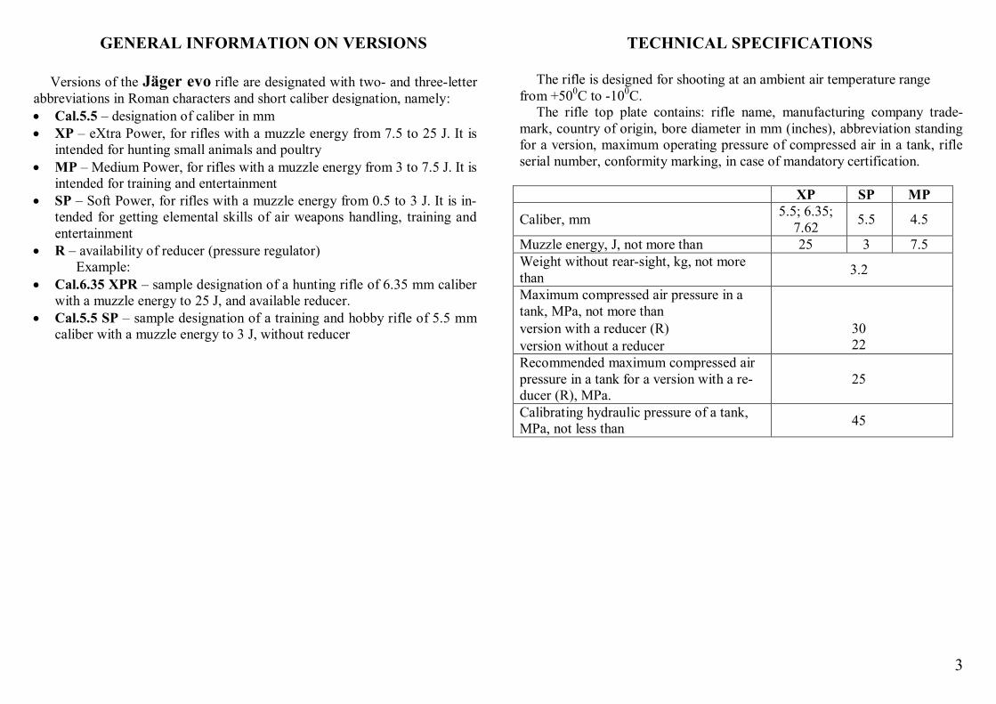
XP SP MP
Caliber, mm 5.5; 6.35; 7.62 5.5 4.5
Muzzle energy, J, not more than 25 3 7.5 Weight without rear-sight, kg, not more than 3.2
Maximum compressed air pressure in a tank, MPa, not more than
version with a reducer (R) version without a reducer
30 22
Recommended maximum compressed air pressure in a tank for a version with a re-ducer (R), MPa.
25
Calibrating hydraulic pressure of a tank, MPa, not less than 45

4
MECHANISM AND PRINCIPLE OF OPERATION
The rifle consists of a top plate with a barrel and a muzzle assembly (without a muzzle assembly), a short gun receiver, a trigger assembly, a crank breechblock, a stock, a magazine (without a magazine), and a tank. (See Annex А)
Rifle breechblock is detachable to provide for easy barrel maintenance from the breech end.
Muzzle assembly serves to shut the compressed air flow following the bullet, and improves the parameters of bullets dispersion.
In the upper part of the top plate, there is a «Weawer»-type base for rearsight mounting and attachment. To enable the magazine usage, the rear-sight rings shall have a height of not less than 22 mm from the plate top, to the bottom surface of the rear-sight tube.
Size-conscious stock back plate is vertically adjusted (in some versions). With turning a breechblock lever by a handle backwards, the firing lock
spring is armed, the trigger assembly is armed, the hammer is set live, and the magazine carrier is rotated to serve the bullet to the ramming line (in case the magazine is available)
With the lever locking (by means of turning towards the barrel), the rammer moving forward towards the barrel rams the bullet from the magazine chamber (carrier) into the barrel
With the lever locking, the slider spring is compressed, and the lever passing beyond the «deadlock» safely locks the bore
By pressing the trigger, the hammer and the hammer catch disengage. The hammer moved by the firing lock spring strikes the valve rod. The valve leaving the seat opens the transfer port to the bore. The rifle fires.
Picture 2. Breechblock 1 – Rammer body. 2 – Rammer. 3 – Lever. 4 – Crank. 5 – Cock. 6 – Lever bushing. 7 – Pin DIN6325 4х6. 8 – Roller. Crank breechblock (picture 2) safely locks the bore due to lever and
crank turning beyond the «deadlock». The rifle top plate containing the breechblock can be of a right-handed and left-handed version. Lever fixing in an open position is provided for by a spring ball in the top plate.
5
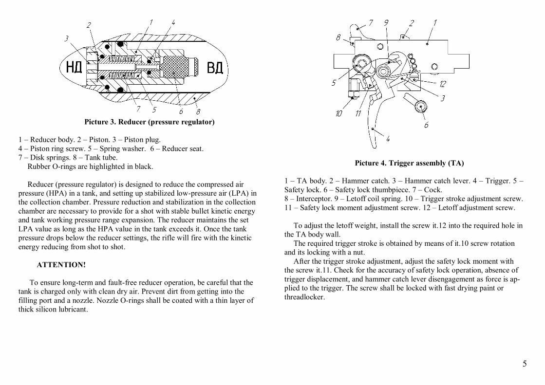
Picture 3. Reducer (pressure regulator)
1 – Reducer body. 2 – Piston. 3 – Piston plug. 4 – Piston ring screw. 5 – Spring washer. 6 – Reducer seat. 7 – Disk springs. 8 – Tank tube.
Rubber O-rings are highlighted in black. Reducer (pressure regulator) is designed to reduce the compressed air
pressure (HPA) in a tank, and setting up stabilized low-pressure air (LPA) in the collection chamber. Pressure reduction and stabilization in the collection chamber are necessary to provide for a shot with stable bullet kinetic energy and tank working pressure range expansion. The reducer maintains the set LPA value as long as the HPA value in the tank exceeds it. Once the tank pressure drops below the reducer settings, the rifle will fire with the kinetic energy reducing from shot to shot.
ATTENTION!
To ensure long-term and fault-free reducer operation, be careful that the
tank is charged only with clean dry air. Prevent dirt from getting into the filling port and a nozzle. Nozzle O-rings shall be coated with a thin layer of thick silicon lubricant.
Picture 4. Trigger assembly (TA)
1 – TA body. 2 – Hammer catch. 3 – Hammer catch lever. 4 – Trigger. 5 – Safety lock. 6 – Safety lock thumbpiece. 7 – Cock. 8 – Interceptor. 9 – Letoff coil spring. 10 – Trigger stroke adjustment screw. 11 – Safety lock moment adjustment screw. 12 – Letoff adjustment screw.
To adjust the letoff weight, install the screw it.12 into the required hole in
the TA body wall. The required trigger stroke is obtained by means of it.10 screw rotation
and its locking with a nut. After the trigger stroke adjustment, adjust the safety lock moment with
the screw it.11. Check for the accuracy of safety lock operation, absence of trigger displacement, and hammer catch lever disengagement as force is ap-plied to the trigger. The screw shall be locked with fast drying paint or threadlocker.
6
SHOOTING OPERATION PROCEDURE
Tank filling with compressed air
Picture 5. HPA charging
If necessary, remove the muzzle assembly Remove the protective cap from the tank Check the nozzle for absence of dirt and damage Attach the filling station to the compressed air source Insert the nozzle into the tank hole as far as it will go Fill in the compressed air Release the pressure in the filling station and remove the nozzle
ATTENTION! Be careful while handling the high-pressure air (HPA) Do not fill in the rifle in the presence of children Always before filling with air take care that the nozzle and the
holes in a tank are clean Nozzle rings shall be coated with thick silicon lubricant or
CIATIM-type grease Fill in the HPA to the pressure specified in section TECHNICAL
SPECIFICATIONS for your rifle version
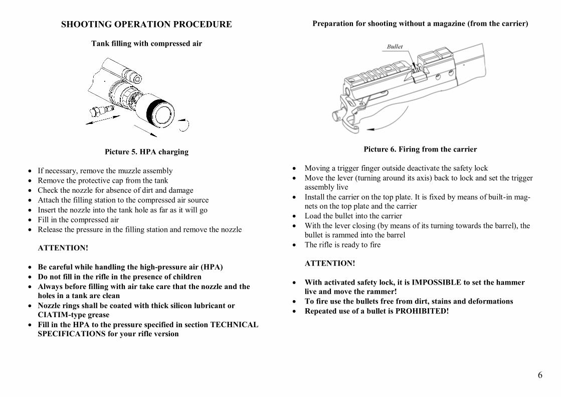
Preparation for shooting without a magazine (from the carrier)
Picture 6. Firing from the carrier
Moving a trigger finger outside deactivate the safety lock Move the lever (turning around its axis) back to lock and set the trigger
assembly live Install the carrier on the top plate. It is fixed by means of built-in mag-
nets on the top plate and the carrier Load the bullet into the carrier With the lever closing (by means of its turning towards the barrel), the
bullet is rammed into the barrel The rifle is ready to fire
ATTENTION!
With activated safety lock, it is IMPOSSIBLE to set the hammer
live and move the rammer! To fire use the bullets free from dirt, stains and deformations Repeated use of a bullet is PROHIBITED!
7
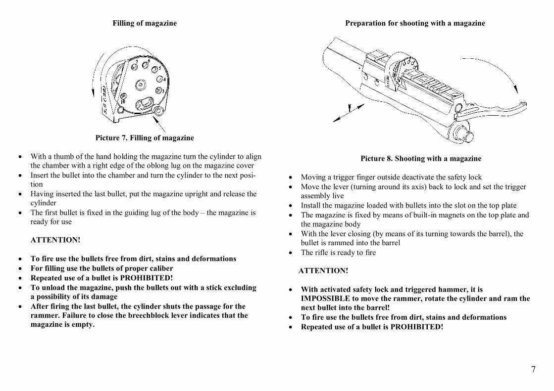
Filling of magazine
Picture 7. Filling of magazine
With a thumb of the hand holding the magazine turn the cylinder to align
the chamber with a right edge of the oblong lug on the magazine cover Insert the bullet into the chamber and turn the cylinder to the next posi-
tion Having inserted the last bullet, put the magazine upright and release the
cylinder The first bullet is fixed in the guiding lug of the body – the magazine is
ready for use ATTENTION!
To fire use the bullets free from dirt, stains and deformations For filling use the bullets of proper caliber Repeated use of a bullet is PROHIBITED! To unload the magazine, push the bullets out with a stick excluding
a possibility of its damage After firing the last bullet, the cylinder shuts the passage for the
rammer. Failure to close the breechblock lever indicates that the magazine is empty.
Preparation for shooting with a magazine
Picture 8. Shooting with a magazine
Moving a trigger finger outside deactivate the safety lock Move the lever (turning around its axis) back to lock and set the trigger
assembly live Install the magazine loaded with bullets into the slot on the top plate The magazine is fixed by means of built-in magnets on the top plate and
the magazine body With the lever closing (by means of its turning towards the barrel), the
bullet is rammed into the barrel The rifle is ready to fire
ATTENTION!
With activated safety lock and triggered hammer, it is IMPOSSIBLE to move the rammer, rotate the cylinder and ram the next bullet into the barrel!
To fire use the bullets free from dirt, stains and deformations Repeated use of a bullet is PROHIBITED!
8
MAINTENANCE AND SERVICE
Barrel cleaning before shooting
The rifle, depending on its version, can be fitted with a tapered barrel (choke), and untapered by Lothar Walther production (Germany). Pro-file and pitch is customized and optimized for each rifle version
The screws fixing the barrel shall be even-tight Before shooting, the bore shall be cleaned with a cleaning rod from the
breech end using BALLISTOL oil (Germany) Cotton wool or wipe cotton cloth (wipe materials) shall be pushed
through the bore with a significant effort providing for grooves filling Cleaning with BALLISTOL oil shall be performed during 3-5 minutes
(5-10 changes of wipe materials) till there are no dirt and lead traces Following BALLISTOL oil, the bore shall be wiped dry with wipe mate-
rials (3-5 changes of wipe materials) till there are no dirt and oil traces Dry wipe material shall be pushed with a significant effort for 10-30
times along the bore Thoroughly wipe the muzzle chamfer
ATTENTION!
Poor (dispersion) results indicate the necessity of bore cleaning Test running takes the first 1000 shots Cleaning frequency increase with rounds Always avoid damage and take care of the muzzle chamfer condi-
tion Use the protective muzzle attachment, unless the moderator is
used
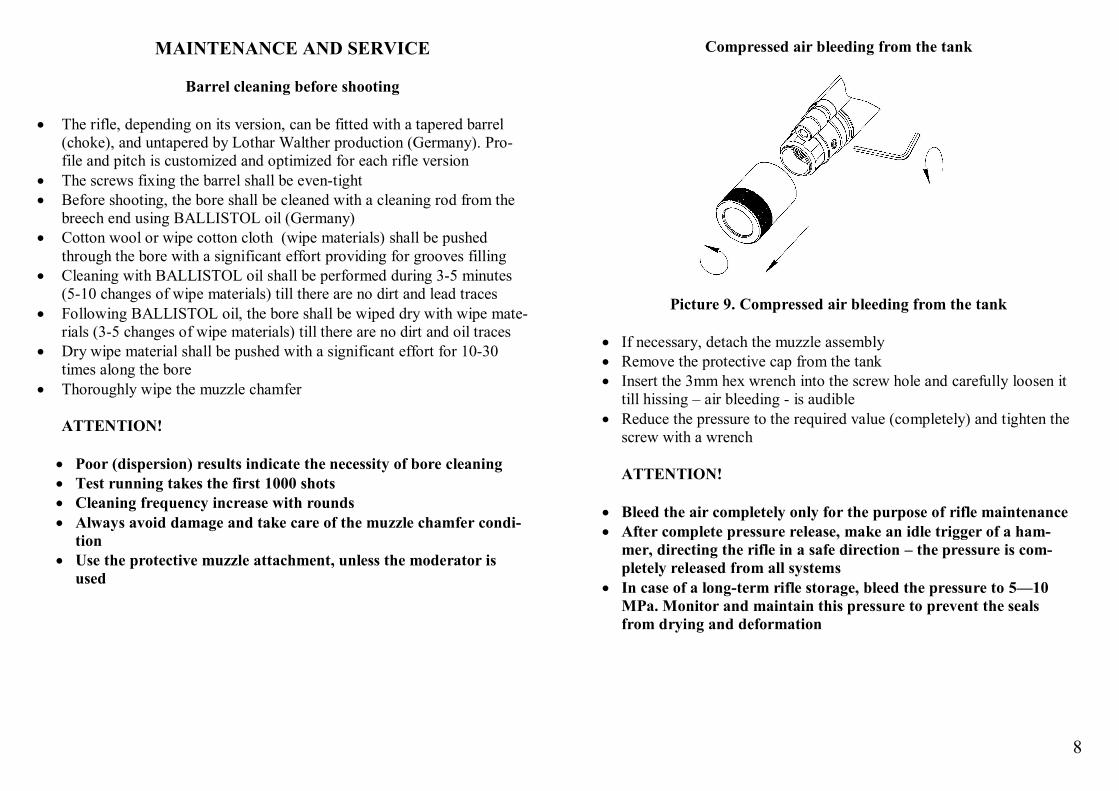
Compressed air bleeding from the tank
Picture 9. Compressed air bleeding from the tank
If necessary, detach the muzzle assembly Remove the protective cap from the tank Insert the 3mm hex wrench into the screw hole and carefully loosen it
till hissing – air bleeding - is audible Reduce the pressure to the required value (completely) and tighten the
screw with a wrench
ATTENTION! Bleed the air completely only for the purpose of rifle maintenance After complete pressure release, make an idle trigger of a ham-
mer, directing the rifle in a safe direction – the pressure is com-pletely released from all systems
In case of a long-term rifle storage, bleed the pressure to 5—10 MPa. Monitor and maintain this pressure to prevent the seals from drying and deformation
9
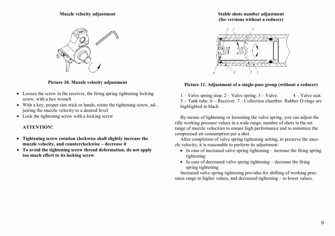
Muzzle velocity adjustment
Picture 10. Muzzle velocity adjustment Loosen the screw in the receiver, the firing spring tightening locking
screw, with a hex wrench With a key, proper size stick or hands, rotate the tightening screw, ad-
justing the muzzle velocity to a desired level Lock the tightening screw with a locking screw
ATTENTION! Tightening screw rotation clockwise shall slightly increase the
muzzle velocity, and counterclockwise – decrease it To avoid the tightening screw thread deformation, do not apply
too much effort to its locking screw
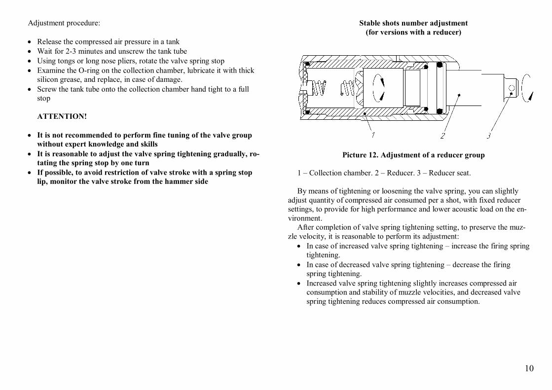
Stable shots number adjustment (for versions without a reducer)
Picture 11. Adjustment of a single-pass group (without a reducer)
1 – Valve spring stop. 2 – Valve spring. 3 – Valve. 4 – Valve seat. 5 – Tank tube. 6 – Receiver. 7 - Collection chamber. Rubber O-rings are highlighted in black By means of tightening or loosening the valve spring, you can adjust the
rifle working pressure values in a wide range, number of shots in the set range of muzzle velocities to ensure high performance and to minimize the compressed air consumption per a shot.
After completion of valve spring tightening setting, to preserve the muz-zle velocity, it is reasonable to perform its adjustment:
In case of increased valve spring tightening – increase the firing spring tightening
In case of decreased valve spring tightening – decrease the firing spring tightening
Increased valve spring tightening provides for shifting of working pres-sures range to higher values, and decreased tightening – to lower values.
10
Adjustment procedure: Release the compressed air pressure in a tank Wait for 2-3 minutes and unscrew the tank tube Using tongs or long nose pliers, rotate the valve spring stop Examine the O-ring on the collection chamber, lubricate it with thick
silicon grease, and replace, in case of damage. Screw the tank tube onto the collection chamber hand tight to a full
stop
ATTENTION! It is not recommended to perform fine tuning of the valve group
without expert knowledge and skills It is reasonable to adjust the valve spring tightening gradually, ro-
tating the spring stop by one turn If possible, to avoid restriction of valve stroke with a spring stop
lip, monitor the valve stroke from the hammer side
Stable shots number adjustment (for versions with a reducer)
Picture 12. Adjustment of a reducer group
1 – Collection chamber. 2 – Reducer. 3 – Reducer seat. By means of tightening or loosening the valve spring, you can slightly
adjust quantity of compressed air consumed per a shot, with fixed reducer settings, to provide for high performance and lower acoustic load on the en-vironment.
After completion of valve spring tightening setting, to preserve the muz-zle velocity, it is reasonable to perform its adjustment:
In case of increased valve spring tightening – increase the firing spring tightening.
In case of decreased valve spring tightening – decrease the firing spring tightening.
Increased valve spring tightening slightly increases compressed air consumption and stability of muzzle velocities, and decreased valve spring tightening reduces compressed air consumption.
11
Adjustment procedure: Release the compressed air pressure in a tank Wait for 2-3 minutes and unscrew the tank tube With a wrench, unscrew the reducer counterclockwise Using tongs or long nose pliers, rotate the valve spring stop Examine the O-rings, lubricate them with thick silicon grease, and re-
place, in case of damage. Screw the reducer into the collection chamber with a wrench hand
tight Screw the tank tube onto the collection chamber hand tight to a full
stop
ATTENTION! It is not recommended to perform fine tuning of the valve group
without expert knowledge and skills It is reasonable to adjust the valve spring tightening gradually, ro-
tating the spring stop by one turn If possible, to avoid restriction of valve stroke with a spring stop
lip, monitor the valve stroke from the hammer side During maintenance, monitor the reducer seat position. Change of
the reducer seat position results in change of reducer working pressure settings, and its possible failure. Reducer seat screwing clockwise by 90 ̊ results in pressure decrease by 15-17 atm.
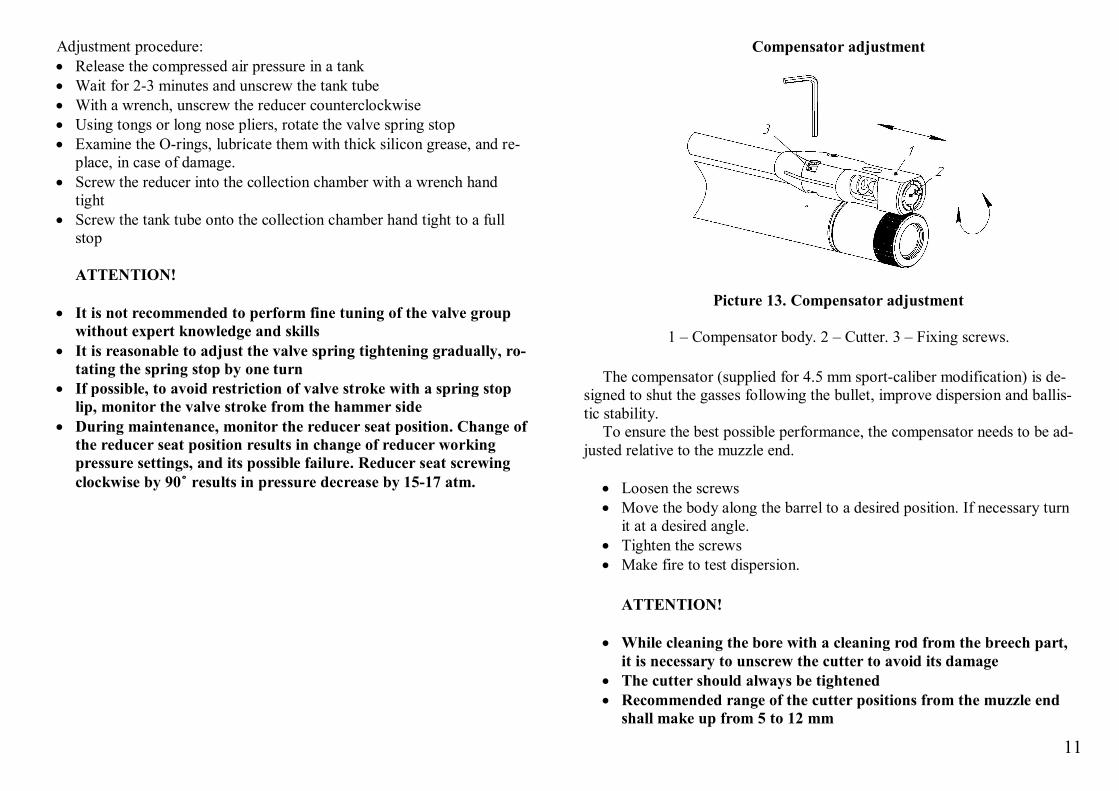
Compensator adjustment
Picture 13. Compensator adjustment
1 – Compensator body. 2 – Cutter. 3 – Fixing screws.
The compensator (supplied for 4.5 mm sport-caliber modification) is de-signed to shut the gasses following the bullet, improve dispersion and ballis-tic stability.
To ensure the best possible performance, the compensator needs to be ad-justed relative to the muzzle end.
Loosen the screws Move the body along the barrel to a desired position. If necessary turn
it at a desired angle. Tighten the screws Make fire to test dispersion.
ATTENTION!
While cleaning the bore with a cleaning rod from the breech part,
it is necessary to unscrew the cutter to avoid its damage The cutter should always be tightened Recommended range of the cutter positions from the muzzle end
shall make up from 5 to 12 mm
12
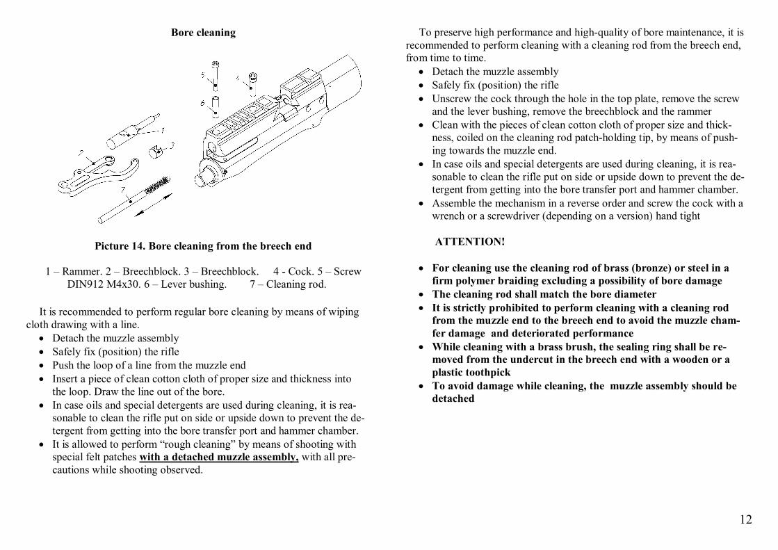
Bore cleaning
Picture 14. Bore cleaning from the breech end
1 – Rammer. 2 – Breechblock. 3 – Breechblock. 4 - Cock. 5 – Screw DIN912 М4х30. 6 – Lever bushing. 7 – Cleaning rod.
It is recommended to perform regular bore cleaning by means of wiping
cloth drawing with a line. Detach the muzzle assembly Safely fix (position) the rifle Push the loop of a line from the muzzle end Insert a piece of clean cotton cloth of proper size and thickness into
the loop. Draw the line out of the bore. In case oils and special detergents are used during cleaning, it is rea-
sonable to clean the rifle put on side or upside down to prevent the de-tergent from getting into the bore transfer port and hammer chamber.
It is allowed to perform “rough cleaning” by means of shooting with special felt patches with a detached muzzle assembly, with all pre-cautions while shooting observed.
To preserve high performance and high-quality of bore maintenance, it is recommended to perform cleaning with a cleaning rod from the breech end, from time to time.
Detach the muzzle assembly Safely fix (position) the rifle Unscrew the cock through the hole in the top plate, remove the screw
and the lever bushing, remove the breechblock and the rammer Clean with the pieces of clean cotton cloth of proper size and thick-
ness, coiled on the cleaning rod patch-holding tip, by means of push-ing towards the muzzle end.
In case oils and special detergents are used during cleaning, it is rea-sonable to clean the rifle put on side or upside down to prevent the de-tergent from getting into the bore transfer port and hammer chamber.
Assemble the mechanism in a reverse order and screw the cock with a wrench or a screwdriver (depending on a version) hand tight
ATTENTION!
For cleaning use the cleaning rod of brass (bronze) or steel in a
firm polymer braiding excluding a possibility of bore damage The cleaning rod shall match the bore diameter It is strictly prohibited to perform cleaning with a cleaning rod
from the muzzle end to the breech end to avoid the muzzle cham-fer damage and deteriorated performance
While cleaning with a brass brush, the sealing ring shall be re-moved from the undercut in the breech end with a wooden or a plastic toothpick
To avoid damage while cleaning, the muzzle assembly should be detached
13
MARKING The rifle top plate contains: rifle name, manufacturing company trade-
mark, country of origin, bullet diameter in mm, abbreviation standing for a rifle version, rifle serial number, conformity marking, in case of mandatory certification. Marking shall be applied in the Russian, German and English languages on different plate sides, correspondingly.
GENERAL INSTRUCTIONS
Before operation, it is necessary to carefully study the Operation Manual
and the rifle mechanism. It is prohibited to modify or introduce changes into the design of rifle
parts and units. Traces of unauthorized intervention, modifications intro-duced into the design of parts and mechanisms shall serve as a ground for refusal in guarantee maintenance of the rifle. It is allowed to adjust on your own only those rifle mechanisms that are described in the Operation Manu-al.
Lead pneumatic bullets of the caliber corresponding to the marking on the rifle body are used for shooting.
To ensure high performance it is recommended to use: Bullets JSB Exact, JSB Express, JSB Heavy, JSB Exact King, JSB
.30, JSB .35 - Czech Republic Bullets H&N Baracuda – Germany Bullets 6,35 SB и 6,35 HP, of varying weight by CJSC Klimovsk
Specialized Ammunition Plant production High-quality bullets by national manufacturers To preserve high performance and reliable mechanisms operation, it is
necessary to protect the bore and the magazines with bullets from dirt and foreign matter.
STORAGE To preserve the rifle in a good working order, it should always be clean. Take care that it has no excess lubricants in the hammer chamber – it af-
fects the dispersion of muzzle velocities. In case of putting for a long-term storage, the rifle shall be thoroughly
cleaned and lubricated. The lubricant layer shall be as thin as possible, the parts shall have no drops and stains on the surface.
The rifle shall be stored in a dry room, without wide temperature fluctua-tions, far from heating appliances, with no aggressive admixtures in the am-bient air.
In order to avoid residual deformation of firing spring in case of a long-term storage, the hammer shall be triggered from the cocked posi-tion.
TRANSPORTATION
The rifle can be transported by all means of transport in covered
transport. Before a flight by plane, use a screw to release the pressure in the tank, as regulations of many air companies prohibit transportation of pres-sure vessels.
The rifle shall be transported in a cover in a special case, protected from blows and falling.
WARRANTIES
The manufacturer guarantees good operation of rifle mechanisms during 3 years from the date of sale or within the rounds of not more than 100 000 shots.
Allowed compressed air leak of not more than 1 MPa a week. The rifle tank shall be inspected at the manufacturing plant every 5 years. Every 10 years, the tank tube shall be replaced with a new one.
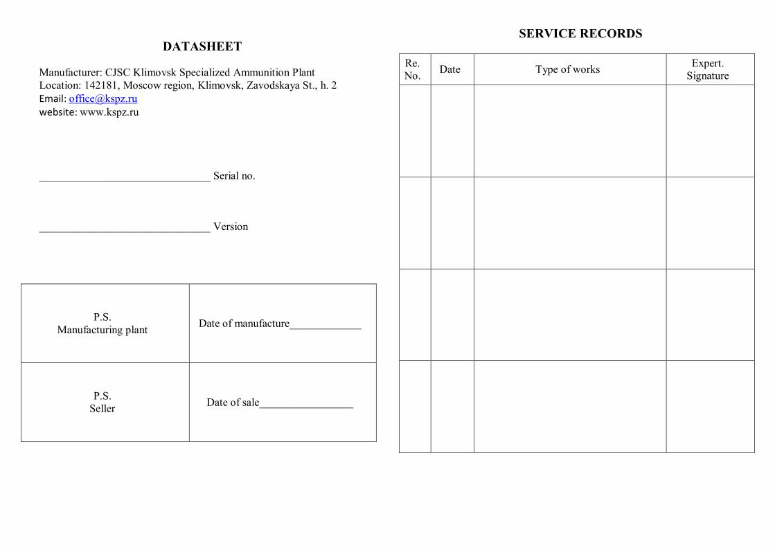
DATASHEET
Manufacturer: CJSC Klimovsk Specialized Ammunition Plant Location: 142181, Moscow region, Klimovsk, Zavodskaya St., h. 2 Email: [email protected] website: www.kspz.ru _______________________________ Serial no. _______________________________ Version
P.S. Manufacturing plant Date of manufacture_____________
P.S. Seller Date of sale_________________
SERVICE RECORDS
Re. No. Date Type of works Expert.
Signature