Embed Size (px)
Citation preview
Extended Target Correction
Coincidence Timing for Transversity
Jin HuangM.I.T.
Hall A Analysis WorkshopDec 14, 2009 @ JLab
&
Jin Huang <[email protected]> 2
Extended Target Correction
• Origin of the Correction• Raster Correction• New Raster Cable Map
Coincidence TOF Calibration for E06010
• Introduction• LHRS Timing• BigBite Timing• Coincidence Timing
Hall A Analysis Workshop
Content
Jin Huang <[email protected]> 3
Extended Target Correction
Origin of the CorrectionRaster CorrectionNew Raster Cable Map
Hall A Analysis Workshop
Jin Huang <[email protected]> 4
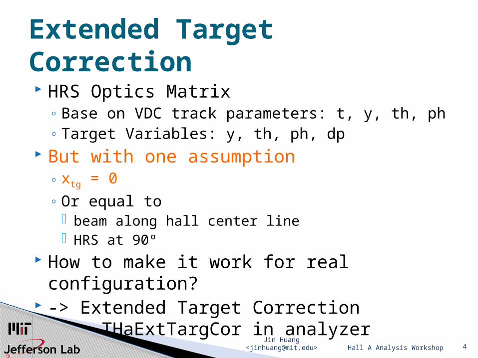
HRS Optics Matrix◦ Base on VDC track parameters: t, y, th, ph◦ Target Variables: y, th, ph, dp
But with one assumption◦ xtg = 0◦ Or equal to
beam along hall center line HRS at 90º
How to make it work for real configuration? -> Extended Target Correction
THaExtTargCor in analyzer
Hall A Analysis Workshop
Extended Target Correction
Jin Huang <[email protected]> 5
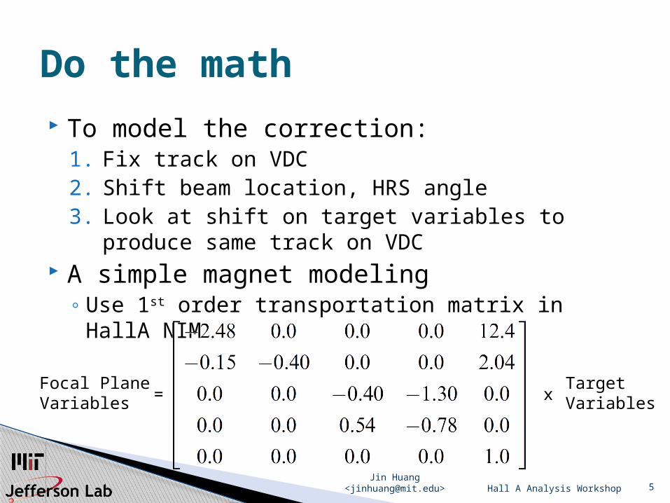
To model the correction:1. Fix track on VDC2. Shift beam location, HRS angle3. Look at shift on target variables to produce
same track on VDC A simple magnet modeling
◦ Use 1st order transportation matrix in HallA NIM
Hall A Analysis Workshop
Do the math
Focal Plane Variables =
TargetVariables x
Jin Huang <[email protected]> 6
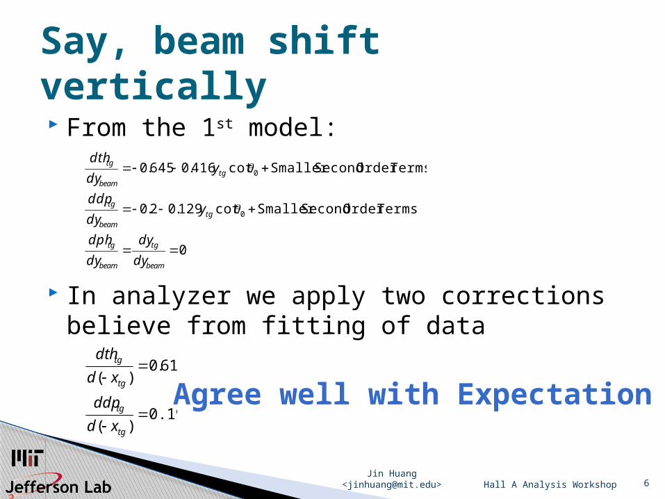
From the 1st model:
In analyzer we apply two correctionsbelieve from fitting of data
Hall A Analysis Workshop
Say, beam shift vertically
0
TermsOrder SecondSmaller cot129.02.0
TermsOrder SecondSmaller cot416.0645.0
0
0
beam
tg
beam
tg
tgbeam
tg
tgbeam
tg
dy
dy
dy
dph
ydy
ddp
ydy
dth
0.19)(
61.0)(
tg
tg
tg
tg
xd
ddp
xd
dth
Agree well with Expectation
Jin Huang <[email protected]> 7
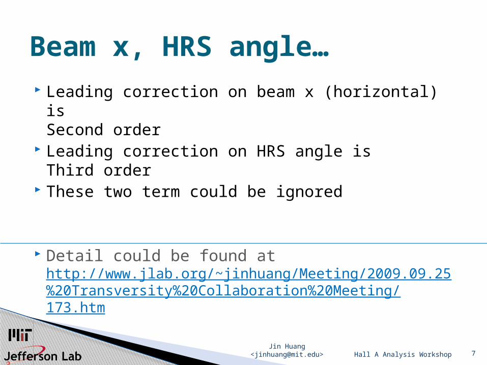
Leading correction on beam x (horizontal) isSecond order
Leading correction on HRS angle isThird order
These two term could be ignored
Detail could be found at http://www.jlab.org/~jinhuang/Meeting/2009.09.25%20Transversity%20Collaboration%20Meeting/173.htm
Hall A Analysis Workshop
Beam x, HRS angle…
Jin Huang <[email protected]> 8
Raster determine beam position Two independent raster: x, y Two raster cable found swapped long before
Transversity◦ New raster cable map ◦ Patch on Analyzer (Sept 09, 2009 -> CVS)
Suggested check for your experiment
Hall A Analysis Workshop
Therefore Raster is important
Jin Huang <[email protected]> 9Hall A Analysis Workshop
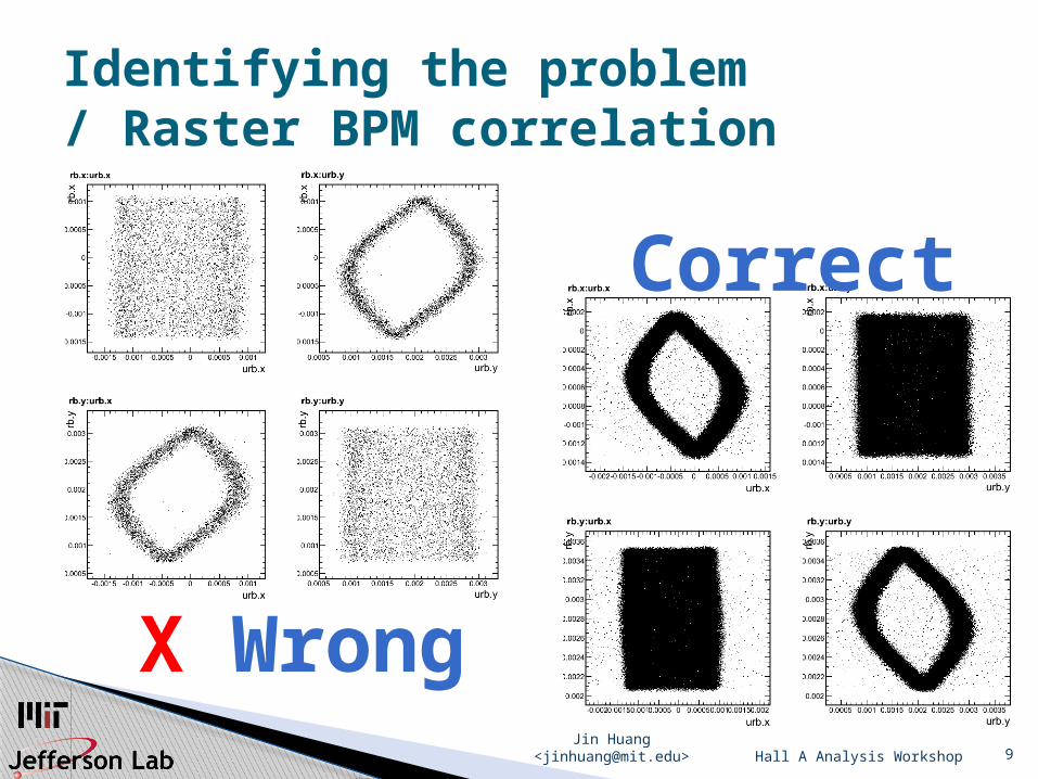
Identifying the problem / Raster BPM correlation
Correct
X Wrong
Jin Huang <[email protected]> 10
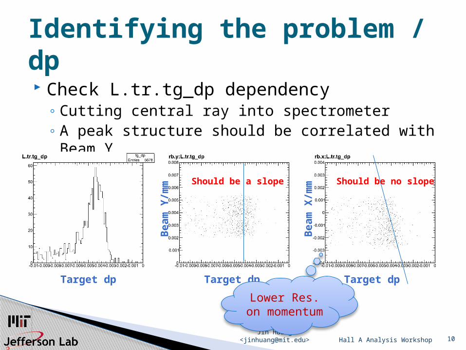
Check L.tr.tg_dp dependency◦ Cutting central ray into spectrometer◦ A peak structure should be correlated with Beam
Y
Hall A Analysis Workshop
Identifying the problem / dp
Beam
Y/m
m
Target dp Target dp Target dp
Beam
X/m
m Should be no slopeShould be a slope
Lower Res. on
momentum
Jin Huang <[email protected]> 11
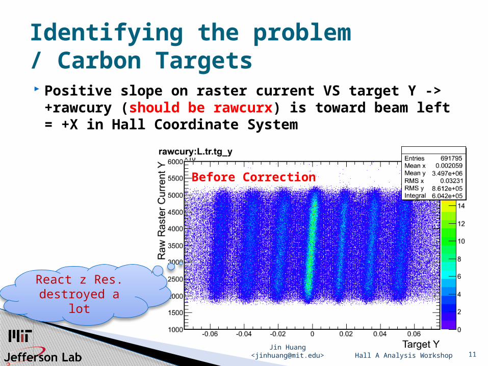
Positive slope on raster current VS target Y ->+rawcury (should be rawcurx) is toward beam left = +X in Hall Coordinate System
Hall A Analysis Workshop
Identifying the problem / Carbon Targets
Before Correction
React z Res.destroyed a lot
Jin Huang <[email protected]> 12Hall A Analysis Workshop
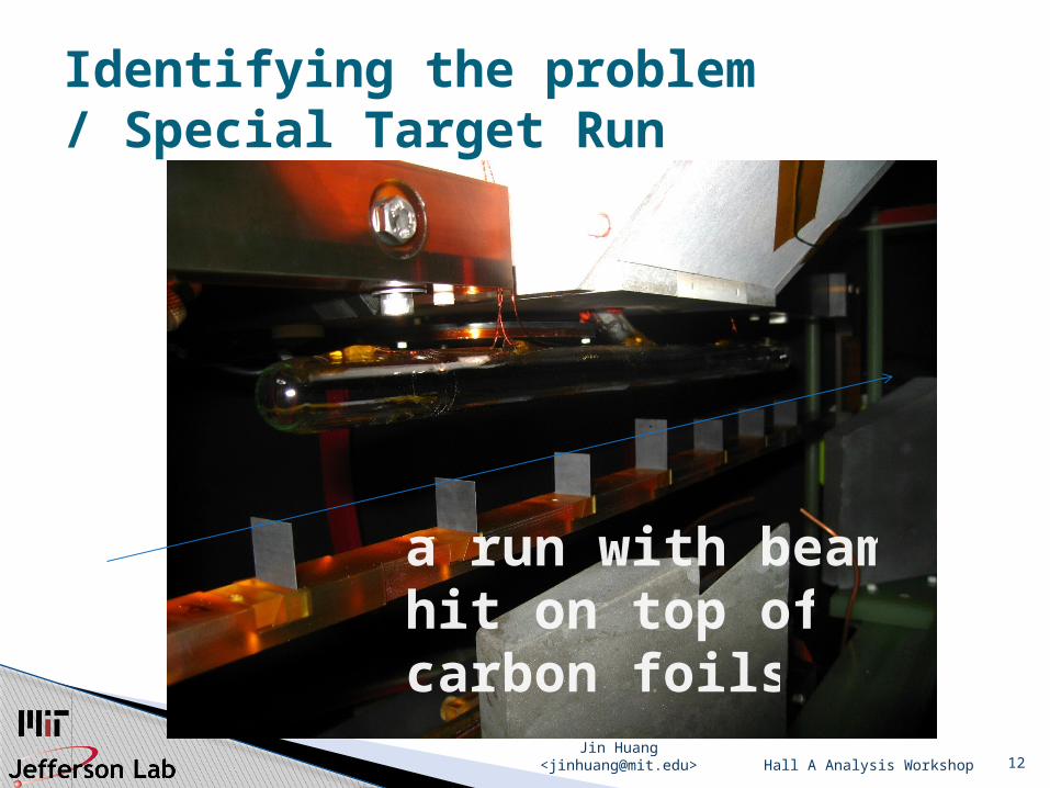
Identifying the problem / Special Target Run
a run with beam hit on top ofcarbon foils
Jin Huang <[email protected]> 13
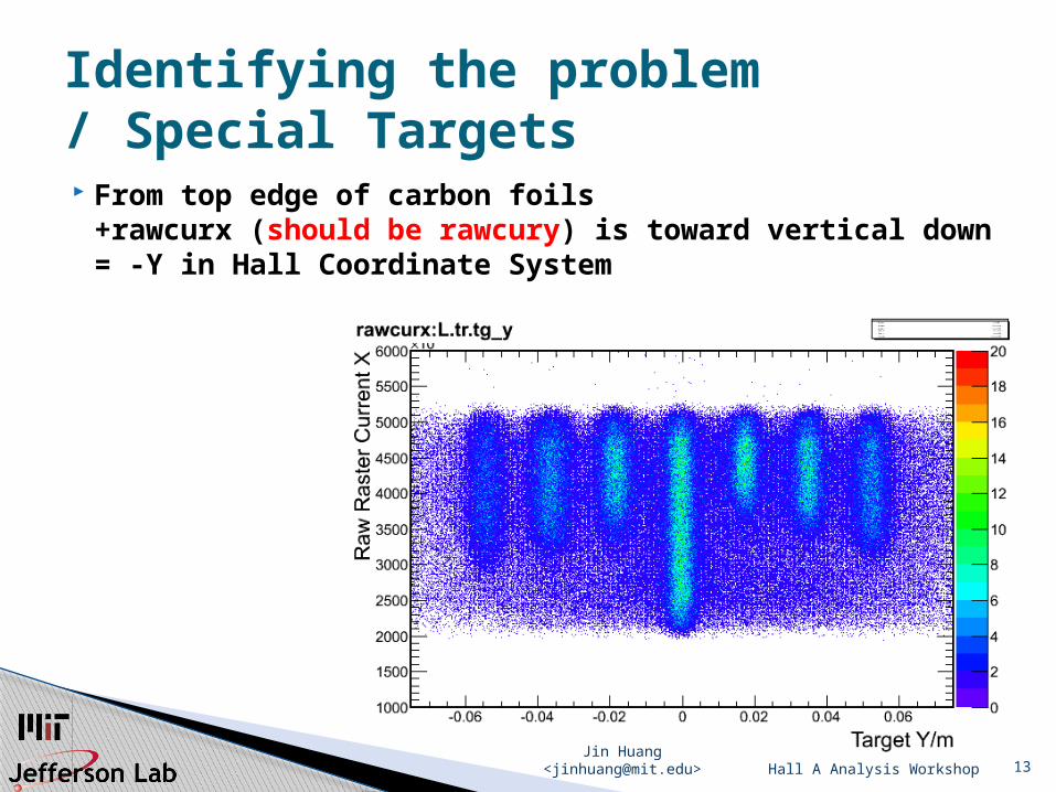
From top edge of carbon foils+rawcurx (should be rawcury) is toward vertical down= -Y in Hall Coordinate System
Hall A Analysis Workshop
Identifying the problem / Special Targets
Jin Huang <[email protected]> 14
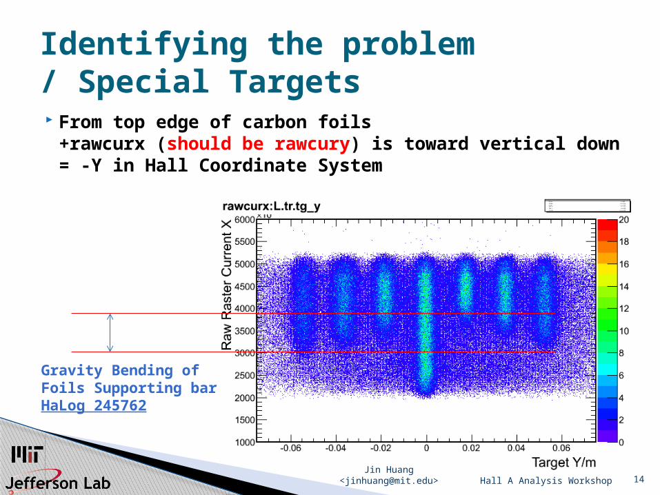
From top edge of carbon foils+rawcurx (should be rawcury) is toward vertical down= -Y in Hall Coordinate System
Hall A Analysis Workshop
Identifying the problem / Special Targets
Gravity Bending of Foils Supporting barHaLog 245762
Jin Huang <[email protected]> 15
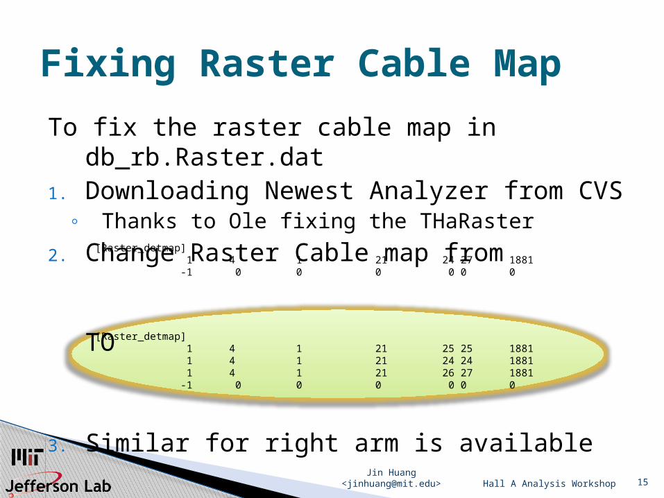
To fix the raster cable map in db_rb.Raster.dat
1. Downloading Newest Analyzer from CVS◦ Thanks to Ole fixing the THaRaster
2. Change Raster Cable map from
TO
3. Similar for right arm is availableHall A Analysis Workshop
Fixing Raster Cable Map
[Raster_detmap] 1 4 1 21 24 27 1881 -1 0 0 0 0 0 0
[Raster_detmap] 1 4 1 21 25 25 1881 1 4 1 21 24 24 1881 1 4 1 21 26 27 1881 -1 0 0 0 0 0 0
Jin Huang <[email protected]> 16
Coincidence TOF Calibration for E06010
IntroductionLHRS TimingBigBite TimingCoincidence Timing
Hall A Analysis Workshop
Jin Huang <[email protected]> 17
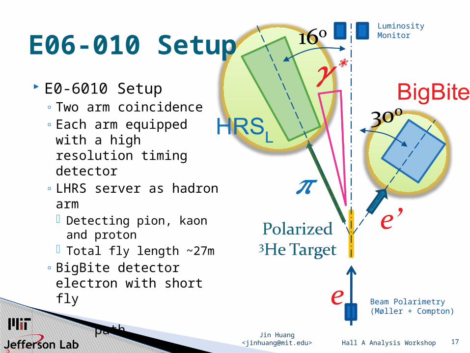
E0-6010 Setup◦ Two arm coincidence◦ Each arm equipped
with a high resolution timing detector
◦ LHRS server as hadron arm Detecting pion, kaon
and proton Total fly length ~27m
◦ BigBite detector electron with short fly path
Hall A Analysis Workshop
E06-010 Setup
Beam Polarimetry(Møller + Compton)
LuminosityMonitor
Jin Huang <[email protected]> 18
coincidence time (CT) between this two spectrometers are defined as the time difference between when two particles are created in the reaction◦ Sharp peak @ 0ns for perfect system◦ Multiple peaks for multi-final state
Useful for◦ Reducing random coincidence background ◦ Help hadron arm PID
Hall A Analysis Workshop
The idea
Jin Huang <[email protected]> 19
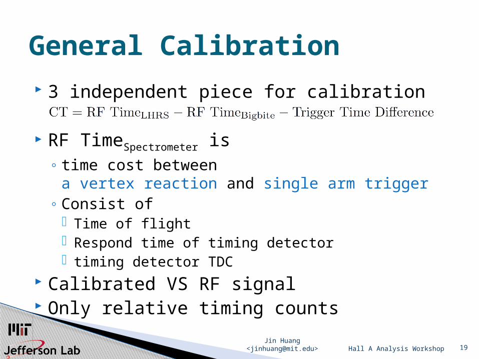
3 independent piece for calibration
RF TimeSpectrometer is◦ time cost between
a vertex reaction and single arm trigger◦ Consist of
Time of flight Respond time of timing detector timing detector TDC
Calibrated VS RF signal Only relative timing counts
Hall A Analysis Workshop
General Calibration
Jin Huang <[email protected]> 20
Timing detector : s2m Optimal Calibration Order
1. Rough offset alignment by looking into two-bar-hit events, with tight ADC cut
To precision below 1ns, so possible for next step2. Fit for matrix elements for fly path length using
RF structure, with tight ADC cut fly path length matrix is similar as optics matrix but
independent Up to 2nd order of xpf and thpf is fine for us
3. Fine bar offset and time walk correction using RF structure
Hall A Analysis Workshop
LHRS Timingby Chiranjib Dutta
Jin Huang <[email protected]> 21
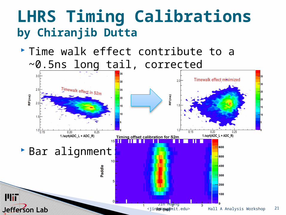
Time walk effect contribute to a ~0.5ns long tail, corrected
Bar alignment:
Hall A Analysis Workshop
LHRS Timing Calibrationsby Chiranjib Dutta
Jin Huang <[email protected]> 22
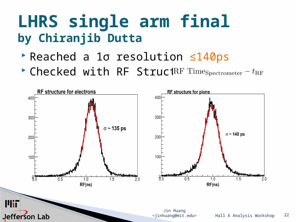
Reached a 1σ resolution ≤140ps Checked with RF Structure
Hall A Analysis Workshop
LHRS single arm finalby Chiranjib Dutta
Jin Huang <[email protected]> 23
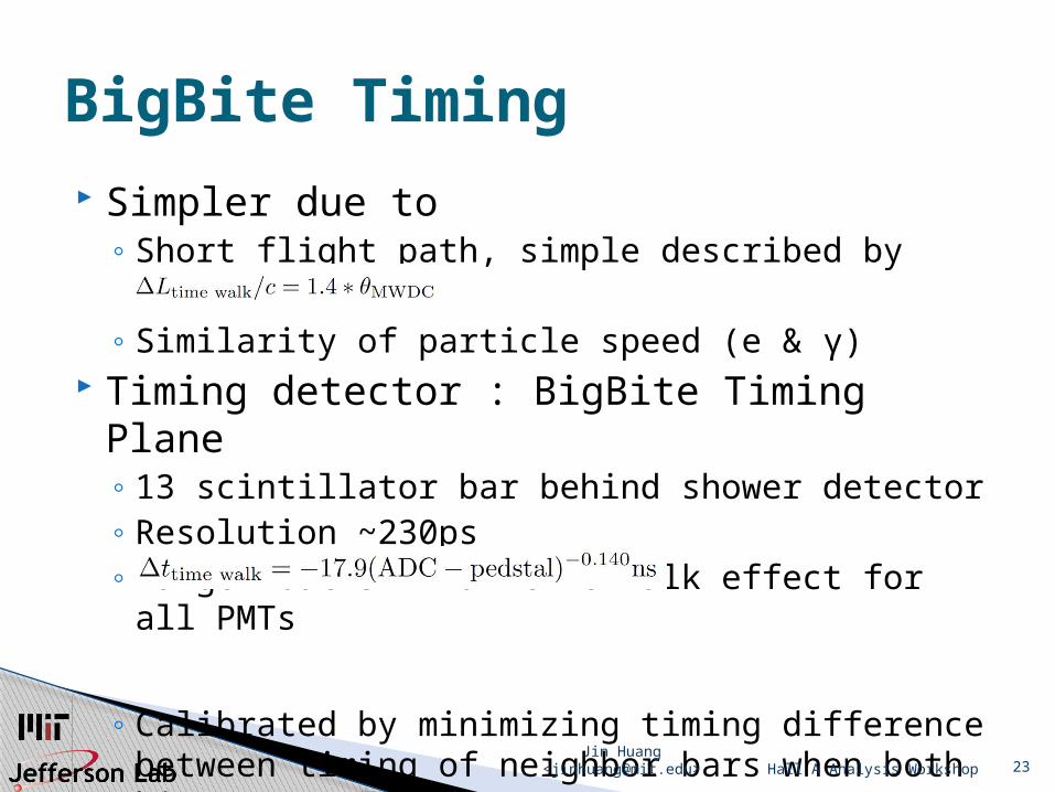
Simpler due to◦ Short flight path, simple described by
◦ Similarity of particle speed (e & γ) Timing detector : BigBite Timing Plane
◦ 13 scintillator bar behind shower detector◦ Resolution ~230ps◦ Larger but similar time walk effect for all PMTs
◦ Calibrated by minimizing timing difference between timing of neighbor bars when both hit
Hall A Analysis Workshop
BigBite Timing
Jin Huang <[email protected]> 24
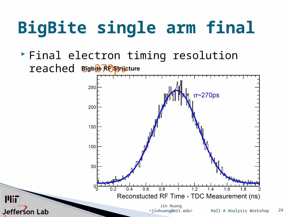
Final electron timing resolution reached σ~270ps
Hall A Analysis Workshop
BigBite single arm final
Jin Huang <[email protected]> 25
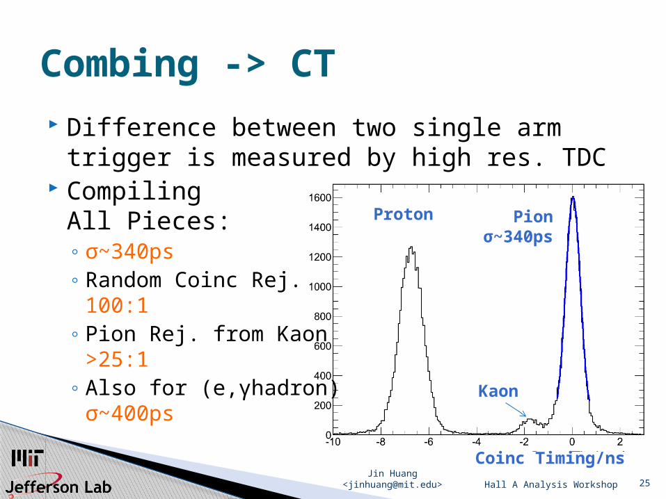
Difference between two single arm trigger is measured by high res. TDC
CompilingAll Pieces:◦ σ~340ps◦ Random Coinc Rej.
100:1◦ Pion Rej. from Kaon
>25:1◦ Also for (e,γhadron)
σ~400ps
Hall A Analysis Workshop
Combing -> CT
Coinc Timing/ns
Proton
Kaon
Pionσ~340ps
Jin Huang <[email protected]> 26Hall A Analysis Workshop
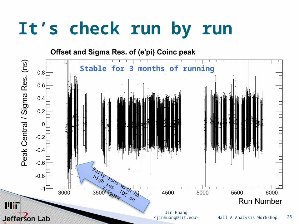
It’s check run by run
Early runs with no
high res. TDC on Trigger
Stable for 3 months of running
Jin Huang <[email protected]> 27
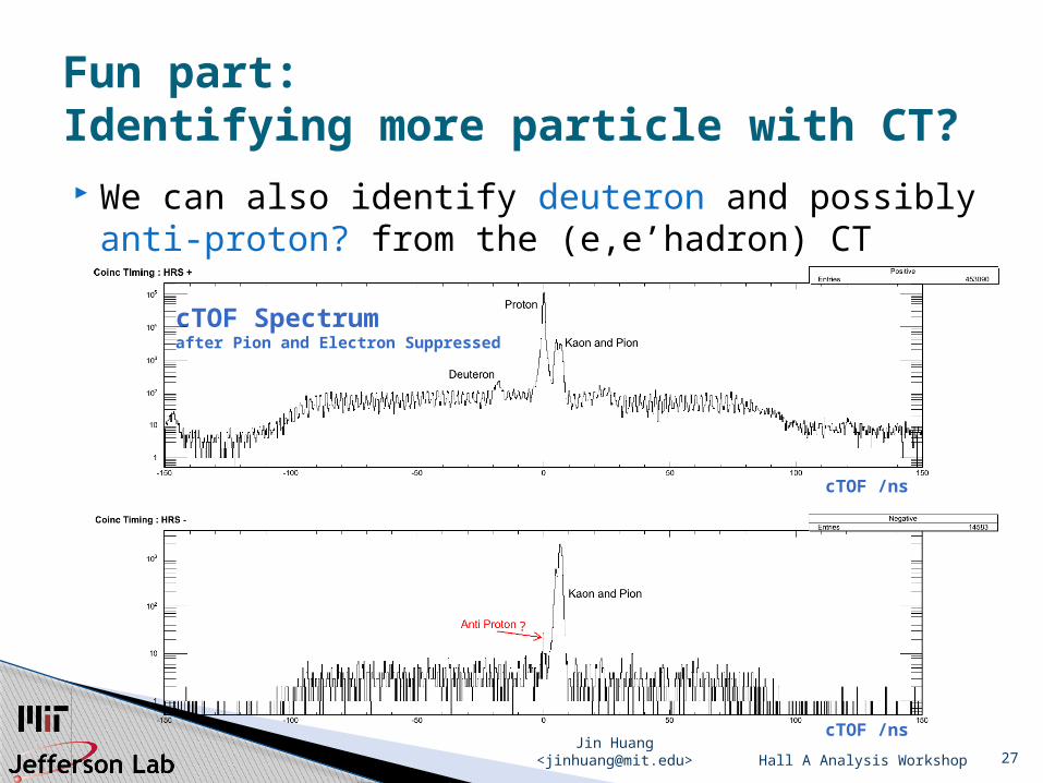
We can also identify deuteron and possibly anti‑proton? from the (e,e’hadron) CT
Hall A Analysis Workshop
Fun part:Identifying more particle with CT?
cTOF /ns
cTOF /ns
cTOF Spectrum after Pion and Electron Suppressed
?

Jin Huang <[email protected]> 28Hall A Analysis Workshop
THE ENDQUESTIONS?
Special Thanks to contributors to this talk • Chiranjib Dutta• Kalyan Allada • Yi Qiang, Vincent Sulkosky, Ole Hansen,
et al,