Embed Size (px)
DESCRIPTION
ISO 13856-1 : 2001
Citation preview

≠ EDICT OF GOVERNMENT ±
JAPAN
In order to promote public education and public safety, equal justice for all, a better informed citizenry, the rule of law, world trade and world peace, this legal document is hereby made available on a noncommercial basis, as it is the right of all humans to know and speak the laws that govern them.
The citizens of a nation must honor the laws of the land.
Fukuzawa Yukichi
JIS B 9717-1 (2011) (English): Safety ofmachinery -- Pressure-sensitive protectivedevices -- Part 1: General principles for designand testing of pressure-sensitive mats andpressure-sensitive floors


JAPANESE INDUSTRIAL STANDARD
Translated and Published by Japanese Standards Association
JIS B 9717-1 :2011
(ISO 13856-1 : 2001)
(JMF)
Safety of machineryPressure-sensitive protective devices- Part 1: General principles for design and testing of pressure-sensitive mats and pressure-sensitive floors
ICS 13.110
Reference number: JIS B 9717·1 : 2011 (E)
PROTECTED BY COPYRIGHT 26 S

B 9717-1: 2011 (ISO 13856-1: 2001)
Date of Establishment: 2011-02-25
Date of Public Notice in Official Gazette: 2011-02-25
Investigated by: Japanese Industrial Standards Committee
Standards Board
Technical Committee on Industrial Machinery
JIS B 9717-1: 2011, First English edition published in 2011-06
Translated and published by: Japanese Standards Association 4-1-24, Akasaka, l'v'Iinato-ku, Tokyo, 107-8440 JAPAN
In the event of any doubts arising as to the contents, the original JIS is to be the £inal authority.
reserved, Unless otherwise specified, no part of this publication tnCly be reproduced or in any form or by any means, electronic or mechanical, including photocopying and
microfilm, without permJssion in writing from the publisher.
Printed in Japan AT
PROTECTED BY COPYRIGHT
B 9717-1 : 2011 (ISO 13856-1 : 2001)
Contents
Page
Introduction ......................................................................................................................... 1
1 ...................................................................... ···· .. ············· .. ··········· .. · .. ····· .. ····· .. ·1
2 Normative references .............................................................................................. 1
3 l'erms and definitions ............................................................................................. 3
4 Requirements .......................................................... ··················· .. ·· .. ······· .. ···············6
4.1 General········· .. ···· .. ·· .. ··· .... ······ .. ············· .. · .. ········ .. ······ .. ··· ...................................... ·· .. ·6 4.2 Actllati11g force ........................................................................................... ······· .. ·····6
4.3 Respollse time ................................................................... ·· .... ······ .... ··· .. ··················7 4.4 Static loading .................................................................. ········· .. ··· .. ·· .. · .. · .. ·· ...... ·· .. ···8 4.5 N ulnber of operatio11s .................................................................................... ·· .. ·····8 4.6 The output state of the sensor .............................................................................. 8
4.7 Response of output signal switching device(s) to the actuating force .... · .. · .... ·8 4.8 Access for maintenance ...................................... " .............................. ·· .... · ........ ·····9
4.9 AdjustlTI.ents· .. ·· .. · .. · ............ ············· .. · .. · .... ·· .. · .... · .. · ........ ·· .... ·· .. · .. ········ .. ········ .. ····· .. ···9 4.10 ConnectiollS ........................................................................ · .... · .. · .. · .. ·········· .. ····· .. ·····9 4.11 Environmental condition,s ............................................................................ ··· .. ···10 4.12 Po\ver supply ........................................................................ · .... ·· ...... · .. · .... · .. · .... · .. ··10 4.13 Electrical equipnle11t ............................................................................................. 11 4.14 E'nclosure ...................................................................... ··· .. ······ .. · ........ ·· .......... ··· .. ···11
4.15 for safety-related parts of control systems in accordance vvith JIS B 9705-1: 2000 ............................................................ ····· .. ··· .. ·· .. ·· .. · ...... 12
4.16 Sensor fixings ........................................................................... ···· .. ········· .. ········ .... ·12 4.17 TrippiIlg .................................................................................................................. 12
4.18 Slipperiness and softness of the sensor top surfaces ....................................... 13 4.19 Additional coverings of surfaces of sensor(s) · .. · .. ··· .............. · .. · .......... · .... · .. ·13 4.20 Failure due to blocking or wedging .................................................................... 13
5 Marking .... · .......................... · .................................... ··· ........ ··· .. · .. ··· ............ ··· .. · .... ···13 5.1 General .. · .. ···· .. ··· .. ··· .. · .. ···· .. ·· .................................................................................... 13 5.2 Marking of the control unit ................................................................................. 13 5.3 Marking of tIle sensor ............................................................................. · .. ···········13
5.4 Marking of other components .. · .......... · ........ · .......... · .. · .... · .. ·· .. · ............ · .. · .... · .. · .. · .. 14
6 Inforlnation for u.se ................................................................................. ·· .. ·· .... ····14
6.1 General······ .. ·· .. ······· .. ··· .... ···· .. ··· .. ··· .... ·· .... ······ .. ··· .. ·· .. ·· .. · ...... · .. · .... ··· .. · .... ··· .. ···· ...... ···14 6.2 Instructions for use .............................................................................................. 14
7 17
7.1 General········· .. ···· .......... ·· ..... ···· .......... ············ .. ·· .. · .. ·· .. ·· .. · ...... · .. · .. ·· ........ ·· .. ····· .... ··· .. 17
PROTECTED BY COPYRIGHT

B 9717-1 : 2011 (ISO 13856-1 : 2001)
7,2 Sensor test sam pie .. , ............................................................................................. 17 7.3 Test pieces for load tests ...................................................................... ·· .. ····· .. ·····17 7.4 Test No. 1-Actuating force .................................................................... ·· ...... ···· .. 18 7.5 Test No.2 - Response tilne .......................................................... · .. ···· .. ···· .. ···· .. ····21
7.6 Test No. 3 - Static loading········ ......... , .................. ····· .. · .... ··· .. ······················· .. ······22 7.7 Test No.4-Number of operations .... ··· .... ·· ...... ·· .. · .. ······· .... ·· ........ ············ .. · .. ······23 7.8 Test No.5-Output state of the sensor .............................................................. 27
7.9 Test No.6 - Response of output signal switching device to the actuating force ................................................................ ······ .. · ...... ······ .. ········ .. ····· .. ·· .. ·············28
7.10 Test No.7-Access for maintenance ...... ·· .. · .. · .. · .... · .. ·· .. · .... ······ .... ······ .... · .. ·· ...... ···28 7.11 Test No. 8-Adjustments ................................................................. ·· .. ·· .. ··· .. ········28 7.12 Test No. 9-Connections ....................................................................... ···· .... ·· ...... 28
7.13 Test No. 10-Environmental conditions .... · .......... · .......... · .... ··· .... · ...... · ........ ·· .... ·28 7.14 Test No. II-Electrical power supply···· ........ ·· .. · .... · .. ··· .... · .. ·· .. ····· ...... · .. ···· ........ ·30 7.15 Test No. 12 - Electrical equipm.ent ................................................................... ···30 7.16 Test No. 13 Enclosllre .................................................................... ···· .. ·· .. ···· .. ·· .. ·30
7.17 Test No. 14-Categodes for safety-related parts of control systems in accordance with JIS B 9705-1: 2000 .... · .. · ...... · .. · .. ····· ...... ·· .... ···· .... · ...... ··· .. · .. · .. · .. ·30
7.18 Test No. 15 - Slipperiness and softness of the sensor top surfaces ...... ··· .. · .. ·30 7.19 Test No. 16 - Additional coverings of top surfaces of sensor(s) .... · ...... · ...... · .. ·30 7.20 Test No. 17-FaHure due to blocking or wedging .. · .. ·· ........ ·· .... · .. · .. · .. · .. · .... · ...... 30
Annex A (normative) Timing diagrams for devices with and without reset ··· .. · .. ·:31
Annex B (informative) Application notes .................................................................... 34
Annex C (informative) Design notes ............................................................................ 38
Annex D (informative) Installation, commissioning and test ······· .... · .. · .. ·· .. ····· .... · .. ·43
Bibliography .................................................................... ······ .... ··· .... ···· .. ·· .. · .. · .. ····· .... ·· ...... 45
(ii)
PROTECTED BY COPYRIGHT
B 9717-1 : 2011 (ISO 13856-1 : 2001)
Forewor d
This translation has been made based OIl the original Japanese Industrial Standard established by the Minister of Health, Labour and Welfare and the 1viinister of EconOlny, Trade and Industry through deliberations at the Japanese Industrial Standards Committee to the proposal for establishment of Japanese Industrial Standard submitted by the Japan lVlachinery Federation (.JIVIF) with the draft being attached, based on the provision of Article 12 Clause 1 of the Industrial Standardization Law.
This JIS document is protected by the Copyright Law.
Attention is drawn to the possibility that some parts of this Standard Inay conflict with a patent right, application for a patent after opening to the public, utility nlodel right or application for registration of utility model after opening to the public which have technical properties. The relevant Ministers and the Japanese Industrial Standards Committee are not responsible for identifying the patent right, application for a patent after opening to the public, utility model right or application for registration of utility Inodel after opening to the public which have the said technical properties.
(iii)
PROTECTED BY COPYRIGHT

~JAPANESE IKDUSTRIAL STANDARD JIS B 9717-1 : 2011 (ISO 13856-1 : 2001)
Safety machinery-Pressure ... sensitive protective devices-Part 1: General principles design and testing of
pressure .. sensitive mats and pressure .. sensitive floors
Introduction
This Japanese Industrial Standard has been prepared based on the first edition of ISO 13856-1 published in 2001 without modifying the technkal contents.
The portions underlined with dots are the matters not stated in the original International Standard.
1 Scope
This Standard specifies requirelnents for pressure-sensitive mats and floors nonnally actuated by the for use as safety devices to protect persons from dangerous machinery. The minimum requirements for the performance, marking and docurnentation are
It covers pressure-sensitive Inats and floors, regardless of type of energy used, e.g. electrical, hydraulic, pneumatic or mechanical.
This Standard covers Inats and floors designed to detect:
a) persons weighing more than 35
b) and persons (e.g. children) weighing m.ore than 20
The detection of persons weighing 20 kg or less is not covered by this Standard.
This Standard does not specify the dimensions or the configuration of the effective sensing area of pressure-sensitive mates) or floor(s) in relation to any particular application.
NOTE: The International Standard corresponding to this Standard and the symbol of degree of correspondence are as follows:
ISO 13856-1: 2001 Saf'ety of' machinery-Pressure-sensitive protective devices-Part 1: General prin~ciples for design and testing of' pressuresensitive mats and pressure-sensitive floors (IDT)
The synlbols which denote the of correspondence in the contents between the relevant International Standard and JIS are IDT (identical), lVIOD (modified), and NEQ (not equivalent) according to ISO/lEe Guide 21-1.
2 Normative references
'rhe following standards contain provisions which, through reference in this text, constitute provisions of this Standard. standards with the year indication, only the editions of the indicated year sha11 be applied and any revisions (including amendments) made thereafter shall not be applied. For those without the indication of the year, the most recent edition (including amendments) shall be applied.
PROTECTED BY COPYRIGHT

2 B 9717-1 : 2011 13856-1 : 2001)
JIS B 9700-1:2004 of lnachiner;y--Basic general principles for 1: Basic tenninologYJ rnethodology
NOTE: Corresponding International Standard: ISO 12100-1: 2003 Safety rrwchinery-Basic general principles for 1: Basic terminology, methodology (lDT)
tJIS B 9700-2: 2004 Safety of concepts, principles for design-Part 2: Technical principles
NOTE: Corresponding International Standard: ISO 12100-2: 2003 Safety of rrtachinery-Basic concepts, principles for 2: Tech-nical prirtciples (lDT)
tJIS B 9705-1: 2000 Safety of machinery-Safety-related parts of control ."tV.">I .. V;fl'i,,'>--'
Part 1: General principles for '-"'"'''' .... '''
NOTE: International Standard: ISO 13849-1: 1999 Safety m.achinery-Safety-related parts of control 1: General prin-ciples for nDT)
JIS B 9706-2: 2001 Safety of machinery-Indication, and actuation-Part 2: for lnarking
NOTE: Corresponding International Standard: lEC 61310-2: 1995 Safety of rrrachinery-Indication, and actuation-Part 2: Requirements j()r marking (IDT)
.JIS B 9715 :2006 Safety of machinery--Positioning of protective equiplnent with respect to the approach of parts of the human body
NOTE: International Standard: ISO 13855: 2002 Safety of lnachinery-Positioning oj' protective UJith respect to the ap-proach of parts of the hUl11an (JDT)
tJIS B 9960-1: 1999 Safety of tnachinery-Electrical equipment ofntachines-Part 1: General requirements
NOTE: Corresponding International Standard: IEC 60204-1: 2000 Safety o{ machinery-Electrical of machines-Part 1: General require-ments (MOD)
JIS C 0025: 1988 Basic environrnental testing procedures Part 2: Tests Test N: Change of temperature
NOTE: vut-rV.L.L\A.Ll.LF, International Standard: lEC 60068-2-14: 1984 Environ-lnental testing-Part 2: Tests. Test lV: '4c/If,'''''VC~C of tenlperature (MOD)
JIS C 0920 of protection provided by enclosures (IP Code)
NOTE: Corresponding International Standard: 60529 Degrees of protection prouided by enclosures (IP code) (lDT)
JIS C 60068-2-3: 1987 Basic environmental testing Part 2: Tests, Test heat, steady state
NOTE: Corresponding International Standard: IEC 60068-2-3: 1969 Basic environnwntal testing procedures-Part 2: Tests-Test Ca: Damp heat, steady state (IDT)
PROTECTED BY COPYRIGHT
3 B 9717-1 : 2011 (ISO 13856-1 : 2001)
JIS C 60068-2-6:1999 Environlnental testing--Part 2: Tests-Test Fc: Vibration (sinusoidal)
NOTE: Corresponding International Standard: IEC 60068-2-6: 1995 Environmental testing-Part 2: Tests-Test Fc: Vibration (sinusoidal) (IDT)
tJIS C 61000-4-2 Electrornagnetic c01npatibility (Ei\1C)-Part 4: Testing and measurement techniques-Sectiort 2: Electrostatic discharge imrnunity test
NOTE: Corresponding International Standard: IEC 61000-4-2 Electrornagnetic compatibility (EMC)-Part 4-2: Testing and measurelnent techniquesElectrostatic discharge immunity test (IDT)
tJIS C 61000-4-3 Electrolnagnetic c01npatibility (EMC)-Part 4-3: Testing and measurement techniques-Radiated, radio-frequency, electromagnetic field imrnunity test
NOTE: Corresponding International Standard: IEC 61000-4-3 Electrolnagnetic compatibility (E.i\1C)-Part 4-3: Testing and m.easurelnent techniquesRadiated, radio-frequency, electrornagnetic field imnlunity test (IDT)
JIS C 61000-4-4 Electr01nagnetic con~patibility (Elv/C)-Part 4-4: Testing and 111eaSUreJnent techniques-Electrical fast transient I burst irnm,unity test
NOTE: Corresponding International Standard: IEC 61000-4-4 ElectrOlnagnetic compatibility (Ei\1C)-Part 4-4: Testing and measurement techniquesElectrical fast transient I burst immunity test (IDT)
JIS C 61000-4-5 Electrornagnetic compatibility (EM C)-Part 4-5: Testing and measurelnent techniques-Surge irnmunity test
NOTE: Corresponding International Standard: lEC 61000-4-5 Electromagnetic compatibility (EMC)-Part 4-5: Testing and measurelnent techniquesSurge immunity test (lDT)
JIS C 61000-6-2: 1992 Electromagnetic c01npatibility (ENlC)-Part 6-2: Generic standards-bnmunity for industrial enuironments
NOTE: Corresponding International Standard: IEC 61000-6-2 Electromagnetic compatibility (EMC)-Part 6-2: Generic standards-Immunity for industrial environments (1VIOD)
ISO 6431: 1992 Pneumatic fluid power-Single rod cylinders, 1 000 kPa (10 baJ~) series, with detachable rnountings, bores frOln 32 nun to 320 mln.. "!vfounting din'tensions
IEC 60439-1: 1999 Low-voltage switchgear and controlgear assemblies-Part 1: T.ype-tested and partially type-tested assemblies
61000-6-3 Electr07nagnetic cornpatibility (EMC)-Part 6-3: Generic standardsEn~ission standard for residential, com~mercial a,nd light-industrial environments
3 Terms and definitions
For the purposes of this Standard, the terms and definitions given in JIS B 9700-1 : 2004 and the following apply.
PROTECTED BY COPYRIGHT
4 B 9717-1 : 2011 (ISO 13856-1 : 2001)
3.1 mat
safety device that detects a person standing on it or who steps on to it comprising a 8e1180r(8) that responds to the application of pressure, a control unit and one or more output signal switching device(s)
See figure 1 and 3.26.5 of JIS B 9700~ 1: 2004.
NOTE: In a pressure-sensitive mat the effective sensing area is deformed locally when the sensor(s) is actuated.
3.2 pressure-sensitive floor
safety device that detects a person standing on it or who on to it comprising a 8ensor(s) that responds to the application of pressure, a control unit and one or 11101'e output signal switching device(s)
See 1 and 3.26.5 of JIS B 9700·1: 2004.
NOTE: In pressure-sensitive floor the effective sensing area is moved as a whole when the sensor(s) is actuated.
3.3 sensor
that part of the pressure-sensitive mat or pressure-sensitive floor that contains an effective sensing area on which the application of an actuating force causes the signal from the sensor to the control unit to change state
3.4 effective sensing area
that part of the top surface area of the sensor or a combination of sensors of the pressure-sensitive mat or pressure-sensitive floor within which a response to an actuating force will take place
3.5 control unit
device that responds to the condition of the 8ensor(s) and controls the state of the output switching device
NOTE: It may also monitor the integrity of the pressure-sensitive lTIat or pressure-sensitive floor (see reference to categories in JIS B 9705-1: 2000) and it may contain facilities to process a reset signal. The control unit Inay be integrated with the machine control system.
3.6 output signal switching device
that part of the pressure-sensitive mat or pressure-sensitive Hoor that, when the sensor or monitoring function means is actuated, responds by producing an OFF state
NOTE: The output signal switching device Inay be integrated with the machine control system.
3.7 actuating force
any force that produces pressure on the effective sensing area to create an OFF state in the output signal switching device
PROTECTED BY COPYRIGHT
5 B 9717-1 : 2011 (ISO 13856-1 : 2001)
3.8 reset
function which permits an ON state in the output signal certain conditions be met
3.9 ON state of output "" ... fiiOA .......... switching
devices, provided
state in which the output circuit(s) is complete and the flow of current or f1uid is possible
3.10 OFF state of output signal switching device(s)
state in which circuit(s) is broken and the flow of current or fluid is interrupted
3.11 response time
time between the start of the application of a force to the effective sensing area and the start of the OFF state of the output switch device (see 4.3)
3.12 dead zone
that part of the top surface area of the sensor outside the effective sensing area
g c
f
e
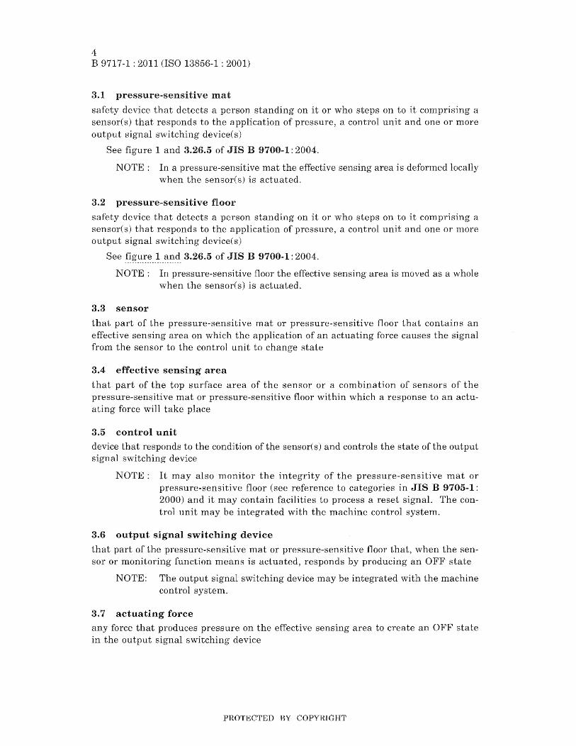
1 Pressure-sensitive mat or floor output signal processing
2 Sensors
3 Control unit-may be integrated with the machine control system
a
4 Output signal switching device(s)-may be integrated with the machine control system
5 Part of the machine control system for pressure sensitive mat/pressure sensitive floor output processing
a Actuating fOl·ce
b Sensor output
c ON state/OFF state
d Manual reset signal (where appropriate alternative to g)
e Reset signal from machine control system (where appropriate)
f Monitoring signals (optional)
g Manual reset signal to the machine control system (where appropriate alternative to d)
h Machine control system(s)
Figure 1 Pressureqsensitive mat or pressure-sensitive floor interfaced with a machine
PROTECTED BY COPYRIGHT

6 B 9717-1 : 2011 (ISO 13856-1 : 2001)
4 Requirements
4.1 General
Pressure-sensitive mats and pressure-sensitive floors shall be able to detect a person who is standing on, or who steps on to the effective area.
4.2 Actuating force
4.2.1 Single sensor (see 7.4.1 and 7.4.2 for test method)
The pressure-sensitive mat or pressure-sensitive floor shall respond to the actuating forces stated in table 1 when the test piece figure 2) is applied over the effective sensing area at a maxiInum speed of 2 mmls within the operating temperature range.
Test pieces 1, 2 and 3 app]y to pressure-sensitive lnats and pressure-sensitive floors designed to detect persons weighing more than 35 Test piece 4 shall additionally be applied to pressure-sensitive mats and pressure-sensitive floors designed to detect persons children) weighing n10re than 20 kg.
Table 1 Actuating force
Application I Test piece Actuating force
I Number d
mm N
For pressure-sensitive mats and 1)1 .:. I 1 11 300 i .vt:
floors rl. '" ...l to detect persons _1. '" more
I I '" 2 80 300 than 35 kg
I 3 200 600
Additional test for pressure-sensitive mats and
I 40 150
pressure-sensitive floors designed to detect persons (e.g. children) weighing more than 20 kg I
I I
4.2.2 Combinations of sensors (see 7.4.3 and 7.4.4 for test methods)
Where an effective sensing area is built up of more than one sensor~ joints and junctions shall fulfil the requirements of 4.2.1 except that only test piece 2 in table 1 applies to pressure-sensitive mats and pressure-sensitive floors designed to detect persons weighing more than 35 kg.
vVhere pressure-sensitive mats and pressure-sensitive floors are designed to detect persons (e.g. children) weighing 20 kg or more only test pieces 2 and 4 shall apply.
For other parts of the effective sensing area, 4.2.1 shall apply (see table 1),
PROTECTED BY COPYRIGHT
7 B 9717-1 : 2011 (ISO 13856-1 : 2001)
If)
o +1 o ('<"\.
'" cb40±O.S
RO.S±O.l
Test piece 1
a
<n o +1 o l()
----------r-----
_l~
cb 80±O.2
Test piece 5
l()
o -H o ~
N o +1 <n
Rl±O.l
If)
o +1 o ~
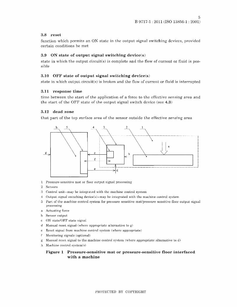
1 Rubber "shoe", 60 Shore A ± 5 Shore A, fixed with adhesive
2 Steel
a Mounting proposal only
For d see table 1.
a
I
Tests pieces 2, 3 and 4
cb8S±O.S
¢ 80±O.2
Test piece 6
Fig-ure 2 Test pieces
4.3 Response time (see 7.5 for test method)
Unit: mm
or. o +1 o ('<"\
3.2
The response time shall be stated by the manufacturer and shall not exceed 200 ms over the operation temperature range. The response time is the time between a) and b) where:
a) .is when a test piece vertically touches the effective sensing area at a velocity of 0.25111/S;
b) is the start of the OFF state of the output signal switching device (see figures A.l, A.2 and A.3).
PROTECTED BY COPYRIGHT
8 B 9717-1 : 2011 (ISO 13856-1 : 2001)
NOTE: The 200 ms limit is specified to prevent the safety device from being defeated by the application of short stepping impulses.
4.4 Static loading (see 7.S for test 111ethod)
4.4.1 After the application of a static force of 2000 N 50 N within the effective sensing area through test piece 2 figure 2), for a period of 8 the output signal switching device shall change state within 2 min of the removal of the force and the deformation shall be no 1110re than 2 rum depth at the lowest part of the top surface after 1 h.
4.4.2 After the application of a static force of 750 N ± 20 N "within the effective sensing area of another location to that used in 4.4.1 through test 1 figure for a period of 8 h, the deformation shall be no more than 2lnm at the lowest part of the top s urfaee after 1 h.
4.5 Number of operations (see 7.7 for test luethod)
4.5.1 A pressure-sensitive mat or pressure-sensitive floor shall perform its function for the typical expected nUlllber of operations.
4.5.1.1 The expected number of operations for the pressure-sensitive mat or pressuresensitive floor is 100000 operations in each of five locations (500000 operations in total), If the effective sensing area consists of a combination of sensors, this requirement shall apply to combination of sensors.
4.5.1.2 In addition, the expected number of operations for the sensor alone is a further one million operations in one other location.
4.5.2 When the requirements of 4.4 and 4.5.1 have been met, the pressure-sensitive mat or pressure-sensitive floor shall still meet the requirements of 4.2 and 4.3.
4.6 The output state of the sensor 7.8 for test method)
The sensor output signal shall change to a value or state which causes the output switching device(s) to change to the OFF state when any actuating force is applied
to the effective sensing area. This value or state shall maintain the output signal switching device(s) in the OFF state until the actuating force is renlOved (see figures A.I, A.2 and A.3).
4.7 Response of output signal s,vitching device(s) to the actuating force (see 7.9 for test method)
4.7.1 General
\Vhen any actuating force is applied to the effective sensing area, the output nal switching device(s) shall change from an ON state to an OFF state. The output signal switching device shall remain in the OFF' state for at least as long as the actuating force is applied.
PROTECTED BY COPYRIGHT

4.7.2 Device with reset
9 B 9717-1: 2011 (ISO 13856-1 : 2001)
For a pressure-sensitive mat or pressure-sensitive floor with the reset nal shaH be manually applied either directly to the control unit of the safety device or alternatively via the Inachine control (see 1).
The reset shall perforn1 the following two functions.
a) Start inhibit interlock At power ON the output switching device(s) shall remain in the OFF state until the reset signal is applied.
b) Re-start inhibit interlock After the actuating force has been removed, the out-put of the output signal switching device(s) shall only to an ON state after the application of a reset .::>.l>; ... uc,.1..
If the reset signal is applied continuously before or whilst the actuating force is applied, the output of the output signal switching device(s) shall not change to an ON state when the actuating force is relnoved (see A.I and A.2).
The reset signal shall control either the output of the sensor and the output signal switching deviceCs) (see A.I) or it shall control the output of the output signal switching device(s) only figure A.2).
4.7.3 Device without reset
For a pressure-sensitive nlat or pressure-sensitive floor without the output signal of the output signal switching device(s) shall change to an ON state at power ON after the actuating force has been removed (see figure
NOTE: If a device without reset is used, then the reset function should be provided in the machine control system (see 5.4 of JIS B 9705-1 : 2000).
4.8 Access for maintenance 7.10 for test Inethod)
'Vhere access is required to the interior of any part of the pressure-sensitive mat or pressure-sensitive floor, it shall be possible only by means of a key or tool. Any means of securing an enclosure shall be captive.
4.9 Adjustments (see 7.11 for test method)
There shall be no method of adjustrnent by the user to actuating force and response time.
Where the supplier states that sub~assemblies of the pressure~sensitive mat or pressure-sensitive floor can be individually replaced, this shall be possible without reducing the overall performance of the pressure-sensitive mat or pressure-sensitive floor and without the need for adjustment.
4.10 Connections (see 7.12 for test method)
The correct alignment of plugs/sockets shall be Inade clear by either type, shape, marking or designation (or a combination of these).
'Vhere components of different configurations within the pressure-sensitive mat or pressure-sensitive floor are interchangeable, incorrect placement or exchange of these components shall not cause a failure to danger.
PROTEc'rED BY COPYRIGHT

10 B 9717-1 : 2011 (ISO 13856-1 : 2001)
a sensor or subsystem is connected by a plug and socket, relnoval or disconnection of the sensor or subsystenl at the plug and socket from or within the control unit shall cause the output signal switching device(s) to go to an OFF state.
4.11 Environmental conditions 7.13 for test method)
The pressure-sensitive mat or pressure-sensitive floor shall continue to operate in the environmental conditions given below or in any wider range stated by the m.anufacturers.
4.11.1 Temperature range
The pressure-sensitive mat or floor shall comply with require-lnents of 4.2.1 and 4.3 over a telnperature range of +5 °C to +40 cC.
NOTE: Extended environmental ten1perature ranges can be -25°C to +40 °e and +5 to +70 °e.
4.11.2 Humidity
The requirements for humidity shall be in accordance with test Ca of ~ns C 60068· 2-3: 1987, for a period of four days.
4.11.3 Electromagnetic compatibility
rrhe pressure-sensitive mat or pressure-sensitive floor shall continue in nonnal operation when subjected to level/class 3 in accordance with table 4 (see 7.13.4).
4.11.4 Vibration
The requirelnel1ts for vibration shall apply to the control unit and the output signal switching device(s) only and shall be in accordance with JIS C 60068-2-6: 1999:
a) frequency range 10 Hz to 55 Hz;
b) displacement 0.15 m.m;
c) 10 cycles per axis;
d) sweep rate one octave per lninute.
NOTE: Special requirements for the sensor are not practicable because of the variation in sizes and shapes of sensors. Sensors are normally fixed to the ground in which case vibration is not normally critical. '¥here a sensor is fixed to a part of a n18chine, the effects of vibration should be considered. See Annex B.
4.12 Power supply
4.12.1 Electrical power supply (see 7.14 for test method)
The pressure-sensitive mat or pressure-sensitive floor shall meet the requirements of 4.3 of JIS B 9960-1: 1999.
4.12.2 Non-electrical power supply
For non-electrical power supplies, the manufacturer shall state the nominal supply level and the permissible range of tolerance within which normal operation will be maintained.
PROTECTED BY COPYRIGHT
11 B 9717-1 : 2011 (ISO 13856-1 : 2001)
Where over-pressure protective devices are not provided, over-pressure variations outside the nominal range shall not result in a failure to danger.
Variations below the operating range shall not result in a failure to danger also EN 982: 1996 and EN 983: 1996).
NOTE: No m.ethods of test have been established for such equipment.
4.13 Electrical equipment 7.15 for test 111ethod)
4.13.1 General
The electrical equipment (cOlllponents) of the pressure-sensitive device shall:
a) conform to JIS and/or International Standards where they exist;
b) be suitable for the intended use;
c) be operated within their specified ratings.
4.13.2 Protection against electric shock
Protection electric shock shall be in accordance with 6.1, 6.2 and 6.3 of JIS B 9960-1: 1999.
4.13.3 Protection against overcurrent
Overcurrent protection shall be provided in accordance with 7.2.1,7.2.3,7.2.7,7.2.8 and 7.2.9 of JIS B 9960-1: 1999.
NOTE: Information may need to be given to the user of the pressure-sensitive device as to the maximum rating of or setting of an overcurrent protective device for the circuit(s) connected to the output connection points of the output switching device(s).
4.13.4 Pollution degree
The electrical equipment shall be suitable for pollution degree 2 in accordance with 6.1.2.3 of IEC 60439-1.
4.13.5 Clearance, creepage distances and isolating distances
The electrical equipment shall be designed and constructed in accordance with 7.1.2 of IEC 60439-1.
4.13.6 Wiring
The electrical equipment shall be wired in accordance with 7.8.3 of IEC 60439-1.
4.14 Enclosure 7.16 for test method)
4.14.1 Sensor
The sensor enclosure shall meet a minimum standard of IP54 (in accordance with JIS C 0920).
When the manufacturer that the sensor can be immersed in water, mlnl-mum enclosure level of the sensor shall be IP67 (in accordance with JIS C 0920).
PROTECTED BY COPYRIGHT
12 B 9717-1 : 2011 (ISO 13856-1 : 2001)
4.14.2 Control unit and output signal switching device enclosure
The control unit enclosure shall meet a minimurn standard of IP54 (in accordance with JIS C 0920). 'Vhere the control unit is designed for mounting in another control equipn1ent enclosure and the enclosure is to a minimum IP54 (in accordance with JIS C 0920), the control unit shall be to a minimum of IP2X (in accordance with JIS C 0920). The enclosure containing the output signal switch deviceCs) shall also meet these requirements.
4.15 Categories for safety~related parts of control systems in accordance with ~JIS B 9705-1 :2000 (see 7.17 for test method).
4.15.1 Pressure-sensitive mats and pressure-sensitive floors shall meet the requirements of the category for which they are specified and marked. These categories are defined in JIS B 9705·1: 2000.
4.15.2 The sensor, control unit and output signal switching device shall meet the requirements of category 1 as a minimum. To meet category 1, the system shall, as a minimunl, meet the requirements of this Standard and the relevant requirements of JIS B 9705-1: 2000.
4.15.3 Electronic control units shall meet the requirements of category 2 as a mininlunl.
NOTE 1 The sensor, control unit and output signal switching device may each have different categories.
NOTE 2 The fault conditions of the sensor and its connections that can be monitored should be taken into account when evaluating the category of the control unit.
NOTE 3 It is not possible at the time of writing this Standard for the majority of sensors to meet all the requirements specified in the categories 2, 3 and 4, in particular when considering mechanical damage and long-term deterioration.
4.16 Sensor fixings (see 7.1.2 for test method)
The sensor shall be provided with a means for fixed pernlanent location.
4.17 Tripping (see 7.1.2 for test method)
When there is a danger that a person can trip on the outside edge(s) of a sensor or sensor covering, a suitable ramp shall be provided. The slope of the ramp shall not exceed 20° from the horizontal. Its existence shall be identified by contrasting colours or lnarking. The ramp shall not create a physical obstruction or other hazard.
\Vhere there is a cOlnbination of sensors andlor additional coverings, provision shall be made to minimize the tripping hazard at joints and junctions between the sensors.
NOTE: There is at present no standard covering this subject, but JIS B 9713-2 can be taken into account when the test method is agreed.
PROTECTED BY COPYRIGHT
13 B 9717-1 : 2011 (ISO 13856-1 : 2001)
4.18 Slipperiness and softness of the sensor top surfaces (see 7.18 for test method)
Provision shall be made on the top surface of the sensor to minimize slipping under the expected operating conditions.
NOTE: There is at present no standard covering this subject, but JIS B 9713-2 can be taken into account when the test Inethod is agreed.
4.19 Additional coverings of top surfaces of sensor(s) (see 7.19 for test method)
The overall requirements of this Standard shall apply to sensor(s) which are fitted with additional or alternative coverings, e.g. protective sheets Annex C).
4.20 Failure due to blocking or wedging (see 7.20 for test nlethod)
There shall be no risk of failure due to build-up of dirt or swarf under the sensor or combination of sensors or their associated connecting parts.
5 Marking (see 7.1.2 for test method)
5.1 General
The pressure-sensitive nlat or pressure-sensitive floor shall be marked in accordance with 6.4 of JIS B 9700·2: 2004 and 18.1 of JIS B 9960-1: 1999.
All labels and marking shall be securely fixed and durable for the expected lifetime of the of the pressure-sensitive m.at or pressure-sensitive floor to which it is at-tached (see JIS B 9706-2).
5.2 Marking of the control unit
The control unit labe1(s) shall also contain the following information, or indicate where this infornlation can be found:
a) the category according to JIS B 9705-1: 2000, speci(ying whether it applies to the control unit only or to the system as a whole;
b) the response time;
c) with or without reset;
d) part number.
5.3 Marking of the sensor
The sensor label shall also contain the following information or indicate where this information can be found:
a) the category according to JIS B 9705-1: 2000;
b) if suitable for detecting persons (e.g. children) weighing lTIOre than 20 kg;
c) the response time;
d) the part number.
PROTECTED BY COPYRIGHT
14 B 9717-1 : 2011 (ISO 13856-1 : 2001)
5.4 of other components
Component parts of the pressure-sensitive mat or pressure-sensitive floor that can be replaced in accordance with the infonnation for use shall be identifiable.
6 for use
6.1 General
Information to be supplied to the user and the way it is presented shall comply with clause 6 of JIS B 9700d 2: 2004.
6.2 Instructions for use 7.1.2 for test method>
6.2.1 General
The instructions for use (e.g. handbook) shall include all the information necessary for safe installation, use and maintenance of the device as listed in 6.2.2 to 6.2.6. See Annexes Band D. The instructions for use shall include the following.
6.2.2 Application
6.2.2.1 Detailed description of the device(s) and a "n:H:.".,..""'"
"Categories in accordance with JIS B 9705-1: 2000 for pressure-sensitive mats and pressure-sensitive floors on machines are stated in type C standards."
Where no type C standard exists, a risk assessment shall be carried out, following the guidelines described in 5.3 of JIS B 9700-1: 2004 and in JIS B 9702 which show the importance of selecting the safety device with appropriate category in accordance \vith Annex B of JIS B 9705-1: 2000.
6.2.2.2 Device features
The category(ies) in accordance with JIS B 9705-1: 2000;
1) the limits of size and shape for individual sensors including effective sensing area;
2) the limits of combination of numbers and sizes of sensor which can be used with one control unit;
3) connections between components.
b) The limits of connection between individual components of the pressure-sensitive mat or pressure-sensitive floor and types of connections.
e.g. cable specification and plugs and sockets;
1) the fitting arrangements - how sensors can be cOlnbined;
2) the fixing arrangements of the sensor and control unit;
3) the mass of the sensor per square meter, and the Inass of the control
4) the sensor additional covering details (where applicable);
5) the response time;
PROTECTED BY COPYRIGHT

6) the power supply requirements;
15 B 9717-1: 2011 (ISO 13856-1 : 2001)
7) the control unit enclosure specifications in accordance with JIS C 0920;
8) the switching capability of the output signal switching device(s);
9) the configuration(s) of the output signal switching device(s);
10) the suitability for detecting walking aids e.g. walking sticks and walking frames.
c) The formula for calculating the required effective sensing area in relation to the hazard location shall be provided. Typical examples of the application of the for-mula shall be given A.5.2 JIS B 9715: 2006).
The range of applications and conditions for which the device(s) is/are intended or approved including category it complies with. Examples of unsuitable applications should also be given;
1) schenlatic representation of the safety functions and exanlples of nlachine control interface circuit diagrams;
2) the rating, characteristics and location of all input/output ternlinals;
3) guidance regarding chemical, physical and environmental resistance (e.g. resistance to solvents, permissible weight loading, operation tenlperature range, pernlissible power supply variation etc.);
4) guidance regarding suitability for wheeled vehicles which may be starting, brakor turning on the surface of the sensor;
5) whether the deviceCs) is/are designed with or without reset in accordance with 4.7.
NOTE: If a device without reset is used, then the reset function should be provided in the machine control system (see 5.4 of JIS B 9705-1 : 2000).
6.2.3 Packaging, transportation, handling and storage
a) description of packaging and methods of unpacking to prevent damage to the device(s);
b) transportation and handling methods to prevent damage or personal injury;
c) storage requirements lay flat, temperature range etc.).
6.2.4 Installation and commissioning
a) instruction that the instruction handbook should be read in full before any installation work is attempted;
b) requirements regarding the surface on which the sensor is to be mounted;
c) installation method including tooling required (see Annex B for guidance);
d) design features of the effective sensing area and the dead zones and how they should be optimized during installation Cincluding drawings where appropriate);
PROTECTED BY COPYRIGHT
16 B 9717-1 : 2011 (ISO 13856-1: 2001)
e) schedule of tests to enable comnlissioning to be carried out after installation in order to establish that the device(s) islare functioning;
f) warning that the overall safety of the Jnachine and its safety deviceCs) depends on the integrity of the interface between them;
g) instruction to check that the category(ies) of the device according to JIS B 9705-1: 2000 is/are appropriate.
6.2.5 Operating instructions
a) purpose and Inethod of operation of actuatorCs) and indicators e.g. starting and restarting;
b) information regarding liInits of use;
c) instructions for fault identification.
6.2.6 Maintenance
a) warning that the maintenance section of the handbook should be read in full before any maintenance is attempted;
b) tasks which require a definite technical knowledge or particular skills and hence should be carried out exclusively by suitably trained, skilled persons;
c) specification of type and frequency of inspection and maintenance;
d) instructions for cleaning;
e) information, e.g. drawings and diagrams enabling trained personnel to carry out fault finding, servicing and repair;
f) details of tests required after replacement of pal-ts to establish that the device(s) fllnction( s) as designed;
g) warning that all covers, clips, edging strips and fastenings removed during maintenance shall be refitted after maintenance and that if such parts are not correctly refitted, the requirements for the device(s) may not be met;
h) list of user replaceable parts specified in sufficient detail to maintain a system which complies with this Standard;
i) warning that only those pal'ts approved by the manufacturer J11ay be replaced by the user and that if non-approved spares are used or non-approved modifications are made, the device(s) may not function to the designed requirements;
j) name and address of manufacturer and com.petent service organization.
6.2.7 Training requirements
Recommendations for the minimunl training requirements of user's personnel including installers, operators and maintenance/inspection staff to ensure that the device(s) is/are installed, used and maintained to comply with this Standard.
PROTECTED BY COPYRIGHT
7 Testing
7.1 General
17 B 9717-1: 2011 (ISO 13856-1 : 2001)
7.1.1 The type tests 1 to 17, described in 7.4 to 7.20, shall determine whether pressure-sensitive mats or pressure-sensitive floors meet the requirements of this Standard. The tests shall be carried out on a ready-to-use pressure-sensitive mat or pressure-sensitive floor. Unless otherwise specified, these tests shall be carried out at 23°C 5°e.
The following are some of the factors which can affect the performance:
a) size of the sensor surface area;
b) top or additional covering Inaterial of the effective o:::>vJ.H:>J.Uf:', area;
c) cOInbination of sensors;
d) length of the interconnecting cables or tubes.
The tests described in 7.4 to 7.20 shall be carried out with the least favourable com.bination of factors for each test.
7.1.2 Where no special test methods are specified, verification shall be by inspection.
7.2 Sensor test sample
The sample(s) shall have a sensor(s) with dimensions of at least 1000 lnm x 500 mm.
If the pressure-sensitive mat or pressure-sensitive floor has only one sensor, two sensors will be required for the tests. One sensor is used to verify the requirements of 4.2, 4.3, 4.4 and 4.5.1.1 (100 000 operations at each of five locations giving 500 000 operations in total), The other sensor is used to verify the requirements of 4.5.1.2 (one million operations at one location) and 4.10.
If the pressure-sensitive mat or pressure-sensitive floor is designed with an effective sensing area built up from a combination of sensors, then a number of sensors for connection with one control unit are required. The combination of sensors will be used to verify the requirements of 4.2 and 4.3. The sensor that is selected for the locations 1 to 16 nlarked on figure 3 is used for verification of the requirement 4.4 and, together with one other sensor, the requirement of 4.5.2. One of the renlaining sensors is used to verify the requirements 4.5.1.2 (one million operations at one location) and 4.10.
7.3 Test pieces for load tests
These tests shall be carried out with the test pieces as shown in figure 2. The test pieces shall be manufactured from aluminium alloy except as specified in figure 2.
PROTECTED BY COPYRIGHT
18 B 9717-1 : 2011 (ISO 13856-1 : 2001)
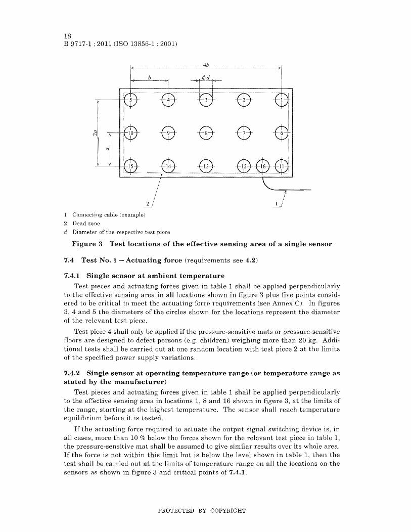
1 Connecting cable
2 Dead zone
cl Diameter of the respective test piece
4b
Figure 3 Test locations of the effective sensing area of a single sensor
7.4 Test No.1 - Actuating force (requirements see 4.2)
7.4.1 Single sensor at ambient temperature
Test pieces and actuating forces given in table 1 shall be applied perpendicularly to the effective sensing area in all locations shown in figure 3 plus five points considered to be critical to Illeet the actuating force requireInents (see Annex C). In figures 3, 4 and 5 the diameters of the circles shown for the locations represent the diameter of the relevant test piece.
Test piece 4 shall only be applied if the pressure-sensitive mats or pressure-sensitive noors are designed to defect persons (e.g. children) weighing more than 20 kg. Additional tests shall be carried out at one random location with test piece 2 at the limits of the specified power supply variations.
7.4.2 Single sensor at operating temperature range (or temperature range as stated by the mallufacturer)
Test pieces and actuating forces given in table 1 shall be applied perpendicularly to the effective sensing area in locations 1, 8 and 16 shown in figure 3, at the limits of the range, starting at the highest telnperature. The sensor shall reach temperature equilibrium before it is tested.
If the actuating force required to actuate the output signal switching device is, in all cases, more than 10 (k, below the forces shown for the relevant test piece in table 1, the pressure-sensitive mat shall be assumed to similar results over its whole area. If the force is not within this limit but is below the level shown in table 1~ then the test shall be carried out at the limits of temperature range on all the locations on the sensors as shown in figure 3 and critical points of 7.4.1.
PROTECTED BY COPYRIGHT

19 B 9717-1 : 2011 (ISO 13856-1 : 2001)
7.4.3 Combination of sensors at ambient temperature
7.4.3.1 \Vhere two or more sensors are combined to constitute one effective C'o.''''''''TntT
area, the same tests as in 7.4.1 shall be carried out on one sensor at the ambient tem-perature. In the following test pieces shall be applied to the effective area at locations on joints as shown in 4 or at locations on a joint and a junction as shown in figure 5.
7.4.3.2 For pressure-sensitive mats and persons weighing more than 35 kg, use test table 1.
floors designed to detect
7.4.3.3 For pressure-sensitive mats and floors designed to detect persons (e.g. children) more than 20 kg, use test pieces 2 and 4 and actuating forces as given in table 1.
Connecting cable (example)
2 Joint line
3 Dead zone
Figure 4 Test locations on the joints between sensors
PROTECTED BY COPYRIGHT

20 B 9717-1 : 2011 (ISO 13856-1 : 2001)
3
1 Connecting cable
2 Joint line
3 Dead zone
Figure 5 Test locations on the joints and on a junction between sensors
7.4.4 Combinations of sensors at operating temperature range (or temperature range as stated by the manufacturer)
7.4.4.1 Where two or more sensors are combined to constitute one effective sensing area, the same tests as in 7.4.2 shall be carried out on one sensor at the limits of the ten1perature range.
In addition, the following test pieces shall be applied perpendicular to the effective sensing area at locations 17, 19 and 21, as shown in figure 4, at the temperature limits or at locations 17, 19, 27 and 28 only, as shown in figure 5, at the telnperature limits. The sensors shan reach temperature equilibrium before are tested.
7.4.4.2 For pressure-sensitive mats and pressure-sensitive floors designed to detect persons weighing more 35 kg, use test piece 2 and actuating force as given in table 1.
7.4.4.3 For pressure-sensitive mats and pressure-sensitive floors designed to detect persons children) weighing more than 20 use test pieces 2 and 4 and actuat-ing forces as in table 1.
PROTECTED BY COPYRIGH'r

21 B 9717-1 : 2011 (ISO 13856-1 : 2001)
7.5 Test No.2 - Response time (requirements see
For this test the sensor configuration which is expected to give the longest response time shall be used.
The response tillle is measured with test 7 figure 6) of (30+8,5) mass and dianleter d of test piece 2 of table 1. If the pressure-sensitive l11at or pressuresensitive floor is designed to detect persons (e.g. children) weighing more than 20 kg, the test is carried out with test piece 8 (see 6) of 05'18,5) kg mass and a diallleter d of test piece 4 of table 1.
The test pieces figure 6) are constructed so that when the lower part of the test touches the effective sensing area with a force than 10 N, an electrical
nal is produced. The test pieces shall be applied to the effective sensing area perpendicularly at a velocity of (0.25_8.03) m/s. The time between the initiation of the electrical signal from the test piece and the start of the OFF state of the output signal switch-
device shall be measured. The tests shall be carried out at locations 1, 4, 8 and 16 shown in figure 3) and at a random location which is expected to give the long-est response time.
vVhen the conlbination of sensors is arranged according to figure 4, the tests shall be carried out on the sensor at locations 1, 8 and 16 (as shown in figure 3), which is expected to give the longest response time because of its location within the combination and at locations 17 and 19 (as shown in figure
When the combination of sensors is arranged as shown in figure 5, the tests shall be carried out on the sensor at locations 1, 4, 8 and 16 (as shown in figure which is expected to give the longest response time because of its location within the combination and at locations 17, 19, 22, 27 and 28 (as shown in figure 5).
The tests shall be carried out at all the above indicated locations at 23°C ± 5°C. At the limits of the specitled temperature range, the tests shall be carried out only at locations 1 and 16 shown in figure 3) and 17 (as shown in figure or 17, 22 and 27 (as shown in figure 5).
PROTECTED BY COPYRIGHT

22 B 9717-1 : 2011 (ISO 13856-1 : 2001)
Connecting eable
2 Insulation
a Mounting proposal only
b Conducting
d Diameter
Unit: mm
Figure 6 Test pieces 7 and 8 to measure the response time
7.6 Test No.3 - Static loading (requirements see 4.4)
NOTE: It is possible that pressure-sensitive floors are designed to be integrated with a machine. In this case it is not possible to carry out the tests required for pressure-sensitive mats.
7.6.1 A static force of 2000 N 50 N shall be applied perpendicular to the effective sensing area through test piece 2 shown in figure 2) for 8 h on a sensor at a random location within 120 mnl of the edges of the effective sensing area.
The output signal switching device shall change to an ON state 2 min after the force has been removed (if the systenl has a reset, it has to be actuated), The deformation of the effective sensing area surface through the test piece shall be measured one hour after removing the force. The depth of the deformation shall not exceed 2 mm measured frOIn the lowest part of the top surface.
7.6.2 A static force of 750 N ± 20 N shall be applied perpendicular to the effective sensing area through test piece 1 (as shown in figure 2) for 8 h at another location within 120 mm of the edges of the effective sensing area.
The output signal switching device shall change to an ON state 2 min after the force has been removed (if the system has a reset, it has to be actuated). The deformation of the effective sensing area surface through the test piece shall be measured one hour after removing the force. The depth of the deformation shall not exceed 2 111m measured from the lowest part of the top surface.
PROTECTED BY COPYRIGHT
23 B 9717-1 : 2011 (ISO 13856-1 : 2001)
7.6.3 \Vithin 30 min of measuring the deformation in 7.6.1 and 7.6.2, the actuating force and response time shall be checked at the location where the test has been performed. For testing the actuating force and the response time, test piece 2 table 1) shall be applied. Test piece 4 shall also be applied when the pressure-sensitive mats and pressure-sensitive floors are desig'ned to detect persons children) weighing more than 20 kg.
7.7 Test No.4 - Number of operations (requirenlents see 4.5)
7.7.1 The tests of requirement 4.5.1.1 (100000 operations at each of five locations) shall be carried out as shown on figures 7 and 8 using test piece 6 (see figure 2). The actuation shall be achieved by supplying a working pressure of 0.38 MPa±0.02 MPa to the pneumatic cylinder in accordance with ISO 6431: 1992 with a 50 mm diameter and a 125 m.m stroke. This working pressure shall also exist at the valve intake (cylinder control) at the moment when the test piece impacts the effective sensing area.
This can be achieved a valve with 6 mm nominal diameter that is direct1y con-nected to the pneumatic cyUnder or through a short air line. This line shall have a nominal diameter;;;; 10 mIn and a length < 200 m.m. A flow control valve shall be installed in the downstream side to achieve an irnpact velocity of (0.55+8.05) mls of the test piece.
Where the effective sensing area consists of a combination of sensors, test piece 6 shaH be applied at location 8~ 16, 23, 24 and 26 as shown on figures 9 and 10. One of these locations has to coincide with the location where the test 7.6.1 has been performed.
For this test, the operations through the test piece 6 (see figure 2) at the effective sensing area shall be in the two directions shown on figure 7 to 10. In each direction~ 50 000 operations shall be performed at each location (giving 100 000 operations in total). During this test, test piece 6 shall be applied 20 tinles to each location consecutively until a total of 50 000 operations has been completed at each 1ocation and in each direction.
During this test, the output signal switching device is connected to the sensor(s) and the pressure-sensitive Inat or pressure-sensitive floor has to be operating. The sensor(s) shall be fixed with fastening elements specified by the manufacturer in the manual.
7.7.2 The test of requirement 4.5.1.2 (one million operations in one location) shall be carried out on a single sensor with the output switching device disconnected, by applying test piece 5 with a mass of 75 kg 1 kg (see figure 2) at a vertical impact velocity of (0.55+g·05 ) nlis. The test piece shall be applied one minion times at a random location on a line 120 mn1 inside the edges of the effective-sensing area.
The test equiplnent surface which supports the sensor shall not move more than 1 mm in a vertical direction while the test is in progress.
During this test, the time of one interval of an actuation shall be (4.0+6"°) s. During each interval, test piece 5 shall touch the effective sensing area for 0.8 s 0.2 s.
PROTECTED BY COPYRIGHT

24 B 9717-1 : 2011 (ISO 13856-1: 2001)
Unit: mm
1 cable (example)
2 Test piece 6 (see 2)
a Dead zone
b Inside diameter of the pneumatic cylinder 50 mm, stroke 125 mm in accordance with ISO 6431: 1992
c Random location
Length of sensor
h Width of sensor
Figure 7 Arrangement of the pneumatic cylinder and locations for the test "Number of operations'\ applied to a single sensor (horizontal component of the force acting parallel to the longest edge of the sensor)
PROTECTED BY COPYRIGHT
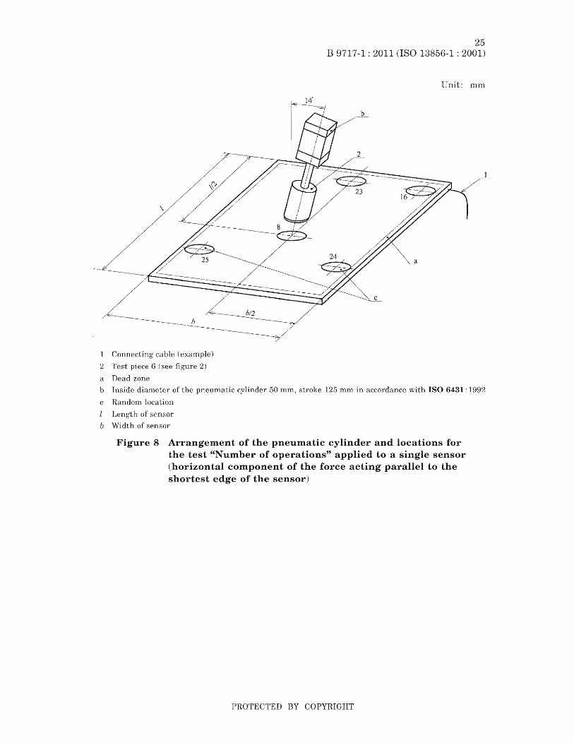
Connecting cable (example)
2 Test piece 6 (see figure 2)
a Dead zone
B 9717-1 : 2011 25
13856-1 : 2001)
Unit: mm
b Inside diameter of the pneumatic cylinder 50 mm, stroke 125 mm in accordance with ISO 6431 : 1992
c Random location
I Length of sensor
b Width of sensor
Figure 8 Arrangement of the pneumatic cylinder and locations for the test "Number of operations" applied to a single sensor (horizontal component of the force acting parallel to the shortest edge of the sensor)
PROTECTED BY COPYRIGHT
26 B 9717-1: 2011 (ISO 13856-1: 2001)
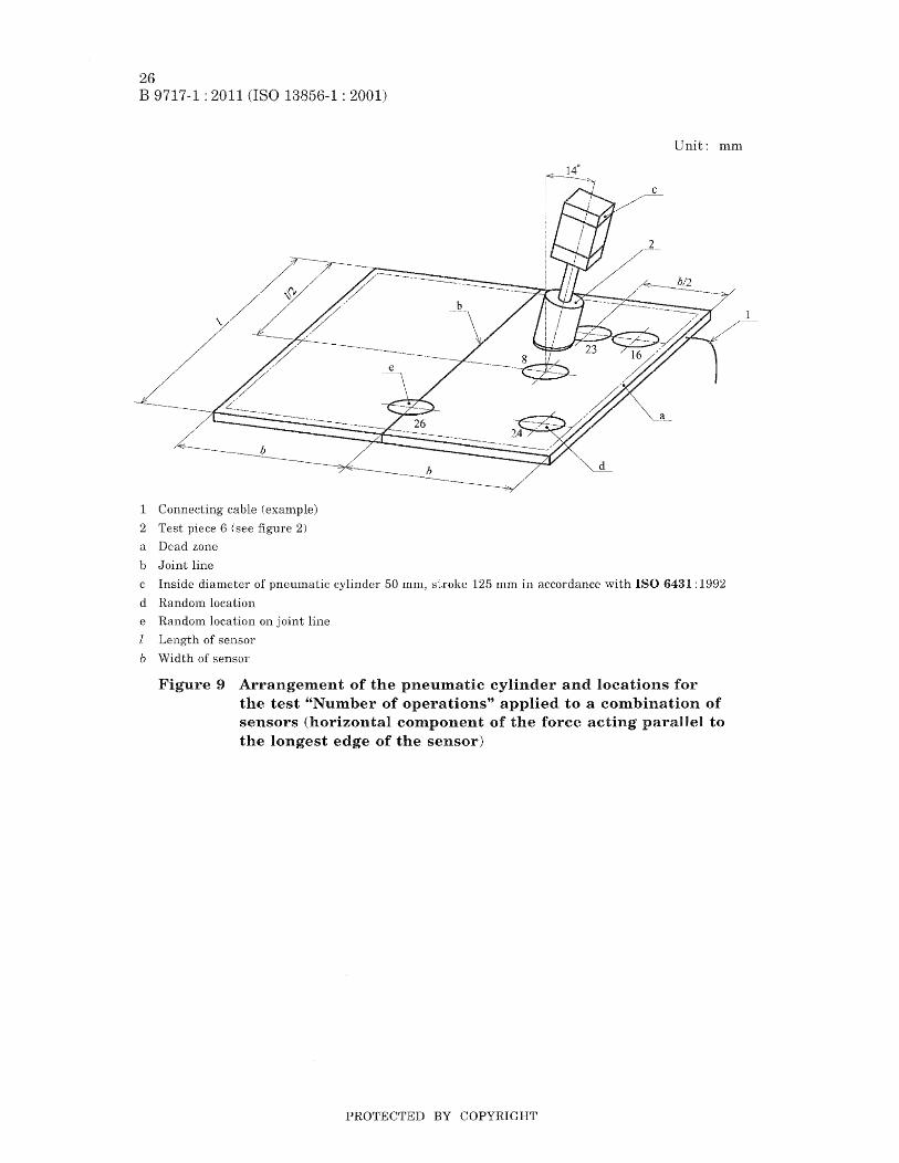
1 co:tln(~ctlmg cable (example)
2 Test piece 6 (see figure 2)
a Dead zone
b Joint line
Unit: mm
c Inside diameter of pneumatic cylinder 50 mll1, stroke 125 mm in accordance with ISO 6431: 1992
d Random location
e Random location on joint line
Length of sensor
b Width of sensor
9 Arrangement of the pneumatic cylinder and locations for the test "Number of operations" applied to a combination of sensors (horizontal component of the force acting parallel to the longest edge of the c£Io ..... nro' .....
PROTECTED BY COPYRIGHT

Connecting cable (example)
2 Test piece 6 (see 2)
a Dead zone
b ,Joint line
27 B 9717-1 : 2011 (ISO 13856-1 : 2001)
Unit: mm
c Inside diameter of pneumatic cylinder 50 mm, stroke 125 mm in accordance with ISO 6431: 1992
d Random location
e Random location on joint line
l Length of sensor
b Width of sensor
Figure 10 Arrangement of the pneumatic cylinder and locations for the test "Number of operations", applied to a combination of sensors (horizontal component of the force acting parallel to the shortest edge of the sensor)
7.7.3 The function of the pressure-sensitive mat or pressure-sensitive floor shall be checked by testing the actuating force using test piece 2 figure 2) and the response time using test piece 7 (see figure 6) at the locations where the tests of 7.7.1 and 7.7.2 have been performed.
If the pressure-sensitive mat or pressure-sensitive floor is designed to detect persons (e.g. children) weighing nlore than 20 kg, additional tests for the actuating force using test piece 4 (see figure 2 and table 1) and for the response tirne using test piece 8
figure 6) shall be applied to the same locations as the previous tests.
7.8 Test No.5 - Output state of the sensor (requirements see 4.6)
Test piece 2 (see figure 2) applying the actuating force as given in table 1 shall be applied perpendicular to the effective sensing area in one random location for a minimum time of 8 h. The output state of the sensor shall change state when this
PROTECTED BY COPYRIGHT

28 B 9717-1 : 2011 (ISO 13856-1 : 2001)
actuating force is applied to it and remain in that state until the actuating force is removed as shown in figures A.l, A.2 and
During this test, the output level of the sensor shall not change to a level which allows the output signal switching device to revert to an ON state.
7.9 Test No.6 - Response of output signal switching device to the actuating force (requirements see
The interaction of separate functions as shown in figures A.1, A.2 and A.3 shall be tested test piece 2 figure 2) and the actuating force as given in table 1 applied perpendicular to the effective area in one random location at room temperature.
7.10 Test No.7 - Access for maintenance (requirements see 4.8)
Testing shall be by inspection.
7.11 Test No.8 - Adjustments (requiren1ents see 4.9)
Testing shall be by inspection and by replacing the sub-assemblies which are authorized by the manufacturer.
7.12 Test No.9 - Connections (req1,1irements see 4.10)
All dissimilar plug-in components that are interchangeable within the pressuresensitive mat or pressure-sensitive floor shall be interchanged one at a time and each plug-in component shall be disconnected with power ON.
7.13 Test No. 10 - Environmental conditions (requirements see 4.11)
7.13.1 Functional test
At the beginning and at the end of the following tests, the function of the pressuresensitive mat and pressure-sensitive floor shaH be verified using test piece 2 (see figure 2) and the actuating force as given in table 1, applied perpendicularly at a speed of 100 mmls ± 5 mmls to the effective sensing area in one randoul location at room. temperature. During this procedure the output signal switching device shall change from an ON state to an OFF state.
7.13.2 Test No. 10.1 - Temperature range (requirements see 4.11.1)
The test, in accordance with table 2, shall be carried out over the temperature range stated by the manufacturer.
Table 2 Temperature range
For heating and cooling, the rate of change of temperature shall be 0.8 °C ± 0.3 °C per min over the whole temperature range. During the test, in accordance with JIS C 0025, the functional test according to 7.13.1 shall be carried out at 1 min intervals. This test can be carried out using a sensor with a smaller effective sensing area than
PROTECTED BY COPYRIGHT

29 B 9717-1: 2011 (ISO 13856-1 : 2001)
that indicated in 7.2. The dinlensions of the effective sensing area shall, however, not be less than 400 mnl x 200 mIn.
7.13.3 Test No. 10.2 -- Humidity (requirement see 4.11.2)
'rhe requirements concerning the resistance to humidity shall be verified in accordance with table 3 for a period of four days.
Table 3 Humidity
After the test of the resistance to humidity, the insulation resistance in accordance with 8.2.2.6 or lEe 60439-1: 1999 has to be verified.
7.13.4 Test No. 10.3 - Electromagnetic compatibility (immunity) (requirements see 4.11.3)
Safety-related requirements shall be verified by reference to lEe 61000-6·3 and lEe 61000-6-2 only. Imrnunity shall be verified for the following three switching states according to the test procedures given in table 4 and with the indicated characteristic values given in the specifications in 7.13.1:
pressure-sensitive mat or pressure-sensitive floor with supply energy;
pressure-sensitive mat or pressure-sensitive floor with supply energy with applied actuating force;
pressure-sensitive mat or pressure-sensitive floor with supply energy, after removal of the actuating force and prior to execution of the reset.
Table 4 Electromagnetic compatibility
Kind Lng and characteristic values Test procedures
Surge installation class 3 JIS C 61000-4-5 power, earth and input/output lines
Electrical fast transients (burst)~ JIS C 61000-4-4 Level 3 duration of test: 2 min.
power, earth and input/output lines
Electrostatic -I: _1- JIS C 61000-4·2
Level 3
Radiated, radio-frequency electromagnetic field, .JIS C 61000-4-3 Level 3
7.13.5 Test No. 10.4 - Vibration (requirements see 4.11.4)
The requirements concerning vibration at the control unit and the output signal switching device only shall be verified in accordance with table 5. At 10 s intervals during this test, there will be a function test in accordance with, 7.13.1 as at the beginning and end of the test.
PROTECTED BY COPYRIGHT

30 B 9717-1 : 2011 (ISO 13856-1 : 2001)
Table 5 Vibration
7.14 Test No. 11- Electrical power supply (requirements see 4.12.1)
The requirelnents of 4.12.1 shall be verified in accordance with the requirements of clause 4 of JIS B 9960-1: 1999
7.15 Test No. 12 - Electrical equipment (requirelnents see
It shall be verified that the electrical equipment meets the requirements listed in 4.13.
7.16 Test No. 13 - Enclosure (requirements see 4.14)
All enclosures shall be tested in accordance with the requirements of JIS C 0920.
7.17 Test No. 14 - Categories for safety-related parts of control systems in accordance with JIS B 9705-1 :2000 (requirenlents see 4.15)
An assessment shall be carried out to confinn that the category clainled for the equipment is in accordance with JIS B 9701-1: 2000.
7.18 Test No. 15 - Slipperiness and softness of the sensor top surfaces (requirements see 4.18)
This requirement shall be tested by inspection until special tests are available, but JIS B 9713·2 can be taken into account when test method is agreed.
7.19 Test No. 16 - Additional coverings of top surfaces of sensor(s) (requirements see 4.19)
This test shall be carried out by selecting the least favourable combination of factors for each test in accordance with 7.1 to 7.18.
7.20 Test No. 17 - Failure due to blocking or wedging (requirements see 4.20)
This requirement shall be verified by inspection and if in doubt by a specific test.
PROTECTED BY COPYRIGHT
Annex
31 B 9717-1 : 2011 (ISO 13856-1 : 2001)
(normative)
Timing diagrams for devices with and without reset
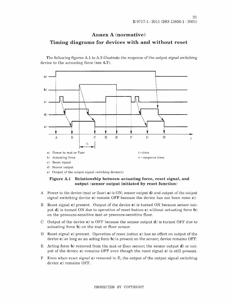
The following A.l to A.3 illustrate the response of the output switching device to the actuating force (see 4.7).
a)
h)
c)
d)
e)
A B C D E F G H
a) Power to mat or floor t =time
b) Actuating force tr = response time c) Reset
d) Sensor output
e) Output of the output signal switching device{ s)
Figure A.I Relationship between actuating force, reset and output (sensor output initiated by reset function)
A Power to the device (mat or floor) a) is ON; sensor d) and output of the output switching device remain OFF because the device has not been reset c).
B Reset signal c) present. Output of the device e) is turned ON because sensor out-put d) is turned ON due to of reset button c) without actuating force b) on the pressure-sensitive mat or pressure-sensitive floor.
C Output of the device e) is OFF because the sensor output d) is turned OFF' due to actuating force b) on the mat or fioor sensor.
D Reset signal c) present. Operation of reset button c) has no effect on output of the device e) as long as an acting force b) is on the sensor; device remains OFF.
E Acting force b) removed from the mat or floor sensor; the sensor output d) or output of the device e) remains OFF even though the reset signal c) is still
F Even when reset rern.oved in E, the output of the output signal device e) remains OFF.
PROTECTED BY COPYRIGHT

32 B 9717~1 : 2011 (ISO 13856-1 : 2001)
G Reset signal c) present. Output of the device is turned ON because sensor output d) is turned ON due to operation of reset button c) without actuating force b) on mat or floor sensor.
H Power to the device (mat or floor) e) are turned OFF.
a)
b)-......... ----~
c) --+-..11
d)
e) - ........ ----11
A B c D
a) Power to mat or floor
b) Actuating force
c) Reset signal
d) Sensor output
is OFF; sensor output d) and device output
E F G H
t time
tr = response time
e) Output of the output signal switching device(s)
Figure A.2 Relationship between actuating force, reset signal and output (sensor output independent of reset function)
A Power to the device (mat or floor) is ON; output of the device e) remains OFF because the device has not been reset c). Sensor output d) is turned ON when the power is turned ON.
B Reset signal c) present without acting force b) on mat or floor sensor. Output of the device e) is turned ON due to the operation of reset button c) as long as the sensor output d) is turned ON.
e Actuating force b) on the mat or floor sensor. The sensor output d) is turned OFF which also turns output of the device e) OFF.
D Reset c) present. Operation of reset button c) has no effect on output of the device as long as an acting force b) is present on the mat or floor sensor; output of the device e) remains OFF.
E Actuating force b) removed from the mat or floor sensor; the sensor output d) is turned ON but the output of the device e) remains OFF even though the reset signal c) is still present.
PROTECTED BY COPYRIGHT
a3 B 9717-1 : 2011 (ISO 13856-1 :
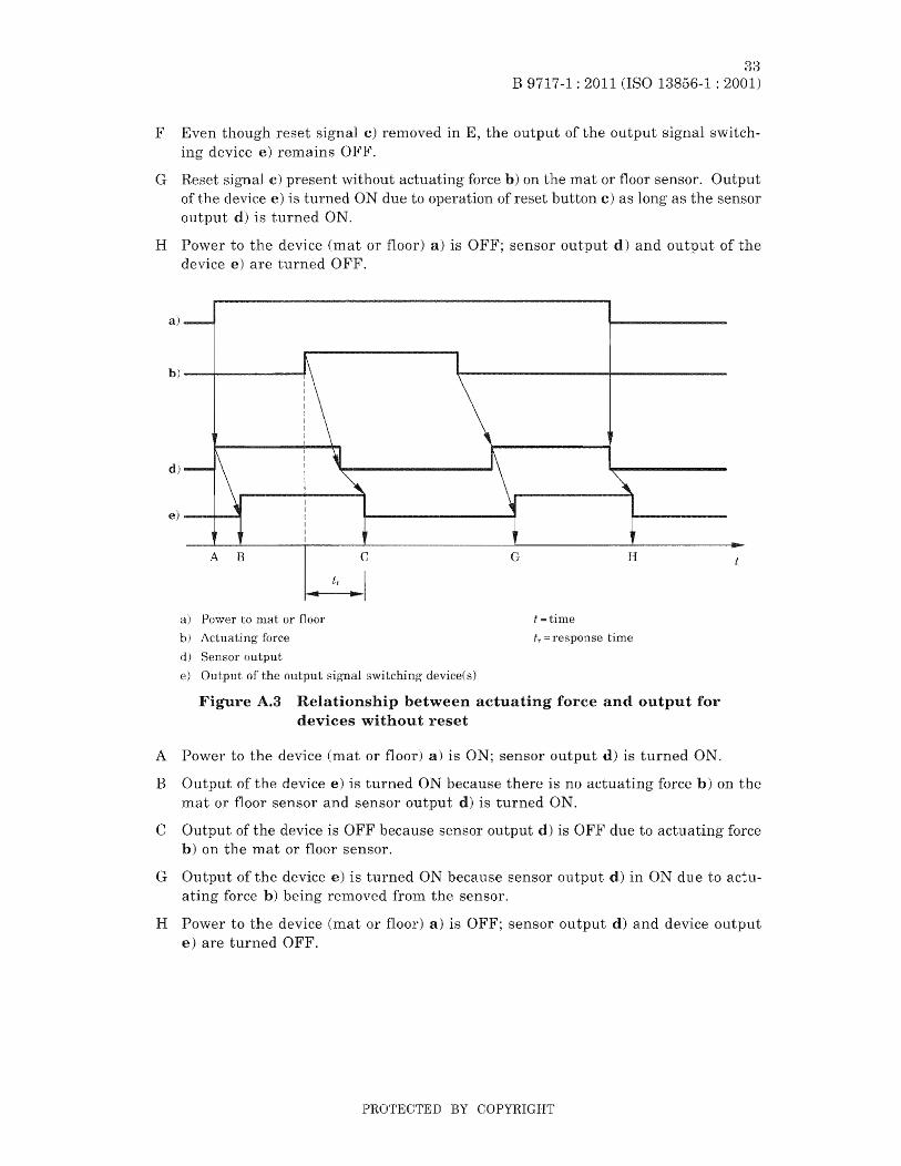
F Even though reset signal c) renloved in device e) remains OFF.
the output of the output signal switch-
G Reset c) present without actuating force b) on the mat or floor sensor. Output of the device e) is turned ON due to operation of reset button c) as long as the sensor output d) is turned ON.
H Power to the device (]nat or floor) a) is OFF; sensor output d) and output of the device e) are turned OFF.
a)
b)-......,..----~
A B
a) Power to mat or floor
b) Actuating force
d) Sensor output
C
e) of the output sig'nal switching' device(s)
G H
t =time
t1':::: response time
A.3 Relationship between actuating force and output for devices without reset
A Power to the device (mat or floor) a) is ON; sensor output d) is turned ON.
B Output of the device e) is turned ON because there is no mat or floor sensor and sensor output d) is turned ON.
force b) on the
e Output of the device is because sensor output d) is OFF due to actuating force b) on the m.at or floor sensor.
G Output of the device e) is turned ON because sensor output d) in ON due to actuforce b) being removed from the sensor.
H Power to the device (mat or floor) a) is OFF; sensor output d) and device output e) are turned 0 FF.
PROTECTED BY COPYRIGHT
34 B 9717-1 : 2011 (ISO 13856-1 : 2001)
B.I General
Annex B (informative)
Application notes
These notes should be regarded as recommendations to manufacturers for inclusjon in the instruction handbook. When selecting pressure-sensitive mats or pressuresensitive floors, a plan should be prepared which contains, amongst other information, the following recommendations.
B.2 Mounting surface (location)
The surface quality should meet the requirements stated by the ll1anufacturer, e.g. irregularities may impair the function of the sensor pressure-sensitive mats and pressure-sensitive floors and therefore should be reduced to an acceptable minimum.
Cable entry points to sensors should be considered in order to ellsure:
that controls are situated in appropriate positions;
b) that no tripping hazards are created due to connecting cables;
c) that no dead zones are created in areas to be protected, e.g. sensors may have a dead zone adjacent to the entry point of connecting cables.
B.3 Size of the sensor
\\Then considering the sensor diInensions, the IninimUln distance to the hazard should be taken into account according to the requirelnents of JIS B 9715: 2006.
B.4 Selection criteria
The following list contains smne features which should be considered when selectthe system:
use as a single device, or in combination with other devices;
b) ability to c01nbine sensors;
c) avoidance of dead zones;
d) frequency of operating cycles and lifetime of the system;
e) output signal switching device switching capacity;
f) static loading, such as parts of machinery resting on the surface;
loading by wheeled traffic, e.g. driving, braking and turning;
h) temperature and humidity;
i) rapid variations in temperature and humidity;
j) effects of chemicals such as oils, solvents, cutting fluids and cOInbinations of these fluids;
effects of flooding, e.g. when cleaning and in case of ,-V,-<-L'L'''''F,'''''''',
PROTECTED BY COPYRIGHT

1) effect of bodies such as
In) additional covering for the sensor;
n) stress due to vibration, cuJ. ... Jv.£,,"'.
35 B 9717-1: 2011 (ISO 13856-1 : 2001)
dust and sand;
0) electro-magnetic such as can be found on certain types of weld-equipment and radio UJ.c;u .. u,;,,,,v
supply voltage fluctuations outside the specification in accordance with JIS B 9960-1, which may be caused by he switching of loads;
q) sensitivity levels which can differ from the requirements of this
r) the need for reset and the location of the reset button;
~·t:H~Q,.n'O._Ql::.n'nT'nTO Inat or pressure-sensitive floor in s) required control category of accordance with JIS B 9705-1 : 2000;
t) need for special wording, signs and marking;
u) sensor fixing.
PROTECTED BY COPYRIGHT
36 B 9717-1 : 2011 (ISO 13856-1 : 2001)
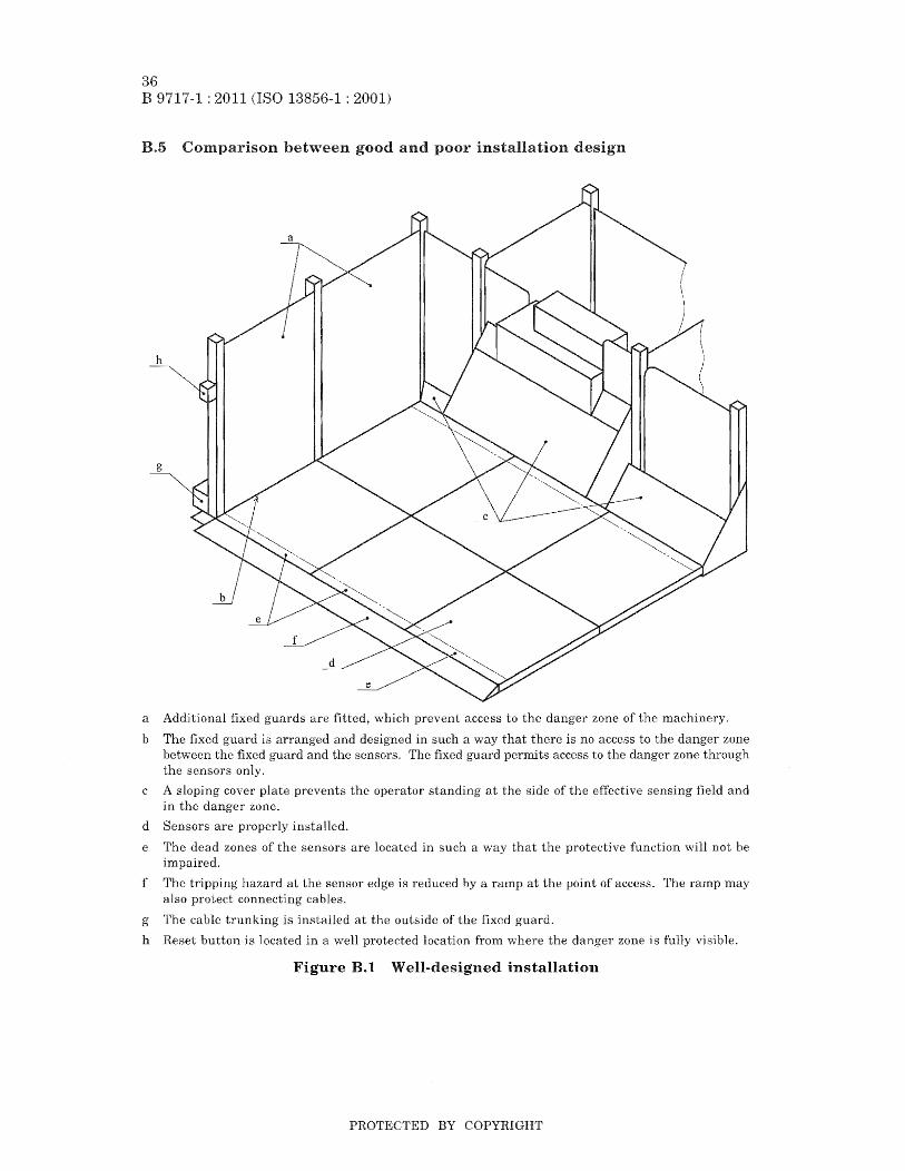
B.5 between good and poor installation design
h
g
a Additional fixed guards are fitted, which prevent access to the danger zone of the machinery.
b The fixed is arranged and designed in such a way that there is no access to the danger zone between the fixed guard and the sensors. The fixed guard permits access to the danger zone through the sensors only.
c A sloping cover plate prevents the operator standing at the side of the effective sensing field and in the zone.
d Sensors are properly installed.
e The dead zones of the sensors are located in such a way that the protective function will not be impaired.
f The tripping hazard at the sensor edge is reduced by a ramp at the point of access. The ramp may also protect connecting cables.
g The cable trunking is installed at the outside of the fixed guard.
h Reset button is located in a well protected location from where the zone is fully visible.
Figure B.1 Well-designed installation
PROTECTED BY COPYRIGHT

a Fixed to the danger zone are not sufficient.
37 B 9717-1 : 2011 (ISO 13856-1 : 2001)
b The danger zone is not protected from the rear and is accessible by reaching over and under the fixed which too smal1.
c The operator can stand on the machinery baseplate in the danger zone.
d The sensors are not property fixed.
e The dead zones of the sensors are located in such a way that the operator can reach the zone.
f Tripping hazards presented by of sensors and trailing cables: trailing cables are not protected against mechanical uU .• HUh'"'
g CabJe trunking is installed on the inside of the fixed and can be misused to provide access to the danger zone.
h The control unit is installed in a vulnerable posiiion and can be to mechanical damage from passing traffic.
Sensors should not be installed on traffic routes.
A service pipe installed above the sensors may be misused and f"H·"''''''rll1''' .... 1-lu swung over the sen-sors into the zone.
k The function and expe(~teCi service life of the sensors will be reduced due to
Access to the zone is rVY',rH711/"1to,/"1 by the baseplates of the fixed guard.
III Sensor not fastened down and a tripping hazard
Figure B.2 Poorly-designed installation
PROTECTED BY COPYRIGHT
38 B 9717-1 : 2011 (ISO 13856-1 : 2001)
Annex
C.l
(informative)
notes
These notes should be to manufacturers, users and testing ~11,rrn'<:>Qr1f\""'" in these design notes does not necessarily
mean that a product is unsafe. It is possible, e.g., that a particular design problem been overcome in an alternative way.
C.2 Conditions
C.2.1 Frequent actuation
When designing mats and pressure-sensitive floors, consideration should be given to the fact that they are also used in applications where they are frequently actuated. In the case of use on production machinery, e.g. when loading a device, more than 3 million operations in the same place can be expected in one year. In the case of pressure-sensitive ID.ats, this can result in a change in sensitivity at the point where the foot is applied.
C.2.2 Infrequent actuation
'\Then designing pressure-sensitive mats and pressure-sensitive floors, consideration should be given to the fact that they are also used in applications where they are only actuated occasionally! at which time they should reliable operation.
C.2.3 Sensor cables
Where two wires in and two wires out are used to detect cable damage, the wires should be connected at opposite ends of the contact element to ensure integrity through the contact element. If wires are connected close together and there is an open circuit joint on to the contact element, an unsafe situation can arise.
C.2.4 Exceptionally heavy loads
In some situations, heavy loads (such as fork lift trucks) can be applied to the sensor during servicing or tool changing. If this is required, the user should clearly identify the need to the manufacturer/supplier.
C.3 Pressure-sensitive mats
C.3.1 General
The sensor of a pressure-sensitive lnat is normally in the form of a sandwich consisting a top surface, a sensing element and a base.
C.3.2 Sensor surface
The sensor top surface should be of a material which will withstand the operating duty to be expected. In addition, applied forces should not lead to permanent deformation that can form "bridges" over part of the effective sensing field.
PROTECTED BY COPYRIGHT
B 9717-1: 2011
The sensor surface should be of a lifetinle non-slip design.
39 13856-1 : 2001)
Consideration should be given to the effects of liquids which can be "'<""",,,",,"l'"r.rt
encountered in the appJication. E.g. some liquids can cause long-term or swelling which \\rill rise to an unsafe condition.
C.3.3 Sensor performance
Sensors can have certain areas which are less sensitive than others and also areas which are more prone to dalnage than others. Sensitivity is often reduced around the edges of a sensor, near the connection with incoming tubes, fibres or leads and at V\I'here sensing plates are held apart. The specified forces should be taken into account.
Life test should be carried out in areas which are more susceptible to damage and early failure. These include cable entries, between the incoming cable and the sensor, and soldered or other connections within the sensor.
C.3.4 Internal air gap
Any gap within the sensor of the pressure-sensitive mat should be kept to a minim.um. Ingress of material, either as small or large particles, or vermin or fluid which may be present in the area where the mat is to be used, can cause the sensor to corrode or to lose its sensitivity.
It is not always possible to detect a very small hole in the surface of the pressuresensitive mat during regular maintenance. However, it nlay be sufficiently large to allow foreign bodies or fluid into the interior of the pressure-sensitive mat. The larger the air gap, the more foreign bodies, fluid or dirt is likely to enter the gap and form a barrier which the sensor being actuated.
C.3.5 Pressure-sensitive nlats with electric sensors
On some designs, electric contact plates are used. The plates are normally separated by an air gap which is closed when a force is applied to the surface. Springs, insulating pads or a foam separate the so that the air gap is created. Consideration should be to the effects of failure of the springs, pads, the resilient foaln and the contact plates. Sensor connections should also be considered.
On other types of electric sensor design, the sensor output will vary in a linear manner dependent on applied force. This can be in the form of a variable resistance, capacitanee or other effeet.
Consideration should be given to the long term stability of variable parts under operating conditions and the effects of of water or other chemicals.
C.3.6 Pressure-sensitive mats with pneumatic sensors
If a force is applied on the effective sensing field of a pneumatic sensor it creates a pressure change as a The time between the application of the force and the
output depends on the location of the applied force. The longest time should be considered.
PROTECTED BY COPYRIGHT
40 B 9717-1: 2011 (ISO 13856-1: 2001)
C.3.7 Pressure-sensitive mats with fibre optic sensors
\Vhen a force is to the effective sensing field of a fibre-optic sensor there is a change in the light passing through an optical fibre. Consideration should be given to the long-tenn changes that can occur in the light en1itters and detectors and in the fibre.
At the design stage, care should be taken that no light be able to go directly fronl the emitter to the detector without going through the fibre.
C.3.8 Connecting cables
In practice, it is foreseeable that sensors may be dragged around by their connecting cables. Consequently, the joint between the connecting cable and the sensor is important. It should withstand both sharp and steady pulls and continuous flexing. Alternatively, a simple nleal1S by which the cable becOInes disconnected without damage and leaves a safe situation, can be used.
C.3.9 Tripping hazard
A tripping hazard exists when the different in height of adjacent horizontal surfaces amounts to 4 mm or more. Measures should he taken that eliIninate the tripping hazard at the surrounding sensor edge. A suitable solution is a ground-flush installation of the sensor, or a fa111p with a 20° slope. Sensors that can be combined should be in such a way that they do not create a tripping hazard in the cOlnbined condition. Lifetime deterioration in hostHe conditions should be considered.
C.4 Pl"essure-sensitive floors
CA.l General
Pressure-sensitive floors have a sensor with a rigid, effective sensing field such as fabricated steel plates.
CA.2 Sensor surface
The sensor top surface should be of a material which will withstand the operating duty to be expected. In addition, applied forces shall not lead to permanent deform.ation that may form "bridges" over part of the effective sensing area.
The sensor top surface should be of a lifetim.e non-slip design.
Consideration should be given to the effects of liquids which can be expected to be encountered in the application. E.g., SOll1e liquids can cause long term degradatjon or swelling into an unsafe condition.
C.4.3 Blocking of the contact travel of sensor surface
It could be possible that the movement of the rigid sensor surface can be blocked due to the following reasons:
a) wedging of sensor surface;
b) build-up of foreign bodies such as e.g. swarf, dust and sand under the sensor surface;
c) warping of sensor surface;
PROTECTED BY COPYRIGHT
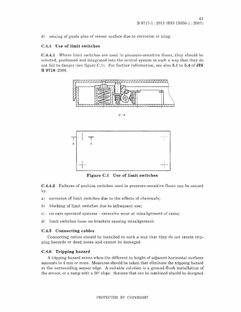
B 9717-1 : 2011
d) "''-',L'''U,~J'';;;' of guide of sensor surface due to corrosion or
C.4.4 Use of limit switches
41 13856-1 : 2001)
C.4.4.1 Where limit switches are llsed in pressure-sensitive floors, they should be selected, positioned and integrated into the control system in such a way that they do not fail to (see C.l). For further infonnation, see also 5.1 to 5.4 of JIS B 9710: 2006.
A-A
A A
Figure C.l Use of limit switches
CAA.2 Failures of position switches used in pressure-sensitive floors can be caused by:
a) corrosion of limit switches due to the effects of chemicals;
b) blocking of limit switches due to infrequent use;
c) on cam operated systems - excessive wear or misalignn1ent of carns;
d) limit switches loose on brackets causing misalignment.
CA.5 Connecting cables
Connecting cables should be installed in such a way that ping hazards or dead zones and cannot be damaged.
CA.6 Tripping hazard
do not create trip*
A tripping hazard exists when the different in height of adjacent horizontal surfaces amounts to 4 mm or more. Measures should be that eliminate the tripping hazard at the surrounding sensor edge. A suitable solution is a ground-flush installation of the sensor, or a ramp with a 20° slope. Sensors that can be combined should be designed
PROTECTED BY COPYRIGHT

42 B 9717-1 : 2011 (ISO 13856-1 : 2001)
in such a way that they do not create a tripping hazard in the cOlllbined condition. Lifetinle deterioration should be considered in hostile conditions. The Inovement of the sensor surface should not be so large as to cause a hazard between it and the surrounding fixed surfaces (see
1 1 Sensor surface
2 Adjacent horizontal surface
Figure C.2 Tripping
CA.7 Removal of sensor surface
The pressure-sensitive floor should be designed in such a way that it does not fail to danger when the sensor surface is renloved.
PROTECTED BY COPYRIGHT

43 B 9717-1: 2011 (ISO 13856-1: 2001)
Annex D (informative)
Installation, commissioning and
D.I General
These notes should be regarded as recolllmendations to nlanufacturers and users concerning installation, commissioning, after installation and regular tests.
AH information for installation, maintenance and of pressure-sensitive mats and floors should be supplied to the user. Recomnlendations should be given including lubl'ication, regular tests and replacement of mechanical and electrical parts. Users should also be provided with appropriate test procedures or systerns to check that the pressure-sensitive mat or floor is operat-
within its specification.
D.2 Installation
D.2.1 For correct installation, information about nlechanical and electrical requirements for the application and, where necessary, installation drawings should be provided.
D.2.2 The manufacturer should state what technical knowledge and particular skills are required to install the pressure-sensitive mat or pressure-sensitive floor.
D.2.3 :Methods of ""'iJV~J.J''''' and inspection for tests carried out after installation should be described.
D.3 Commissioning
D.3.1 Comnlissioning should include examination and tests carried out by trained and competent persons.
D.3.2 The results of the examination and tests should be recorded, and copies of this record should be kept by the user.
D.3.3 comJnissioning, the points should be considered.
a) Check that the mounting surface and environrnental conditions are suitable for the device( s) in use.
b) Check the minimum distance in accordance with the requirements of JIB B 9715:2000
c) Check that the sensor is fastened securely in hazard.
and does not provide a trip
d) Ensure that any "dead zones" do not provide an access path to the hazard.
e) Check that the removal of power supply from the pressure-sensitive nlat or pressure-sensitive floor prevents further operation of the m.achine. The machine shou1d not be capable of being reactivated until power has been restored and the reset operated.
PROTECTED BY COPYRIGHT

44 B 9717-1 : 2011 (ISO 13856-1 : 2001)
f) Check that a hazardous movement is prevented while an actuating force is applied to the effective area.
g) Ensure that additional have provided, where necessary, to pre-vent access to the dangerous parts of machinery from any direction not protected by the pressure-sensitive mat or pressure-sensitive floor.
h) Check that the presence of a person between the danger zone and the sensor is prevented. If this is not possible, check that further safety nleasures are taken.
i) Check that all indicator lamps are functioning correctly.
j) Check the sensitivity of the pressure-sensitive nlat or pressure-sensitive floor over the whole effective sensing area.
k) The adequate safety required for a machine depends on the integrity of the interface between the machine and its protective device(s). Where a category is stated in accordance with JIS B 9705-1: 2000 by a type C standard or a risk assessment, the checks should ensure the machine control circuits and the connections to the safety device(s) are in accordance with the interface connections agreed between the Ina chine control manufacturer and the safety protective device manufacturer.
1) Where muting is provided, ensure that muting occurs only during the intended part of the machine's operation, e.g. during the cycle where no hazard exists (see JIS B 9705-1),
D.4 Regular inspection and tests
D.4.1 It is recommended that regular examination> inspection and test procedures be carried out by qualified and C0111petent persons.
D.4.2 The examination set out in D.3.3 should be repeated.
D.4.3 During regular inspections check that no modifications have been made to the system and no changes (such as wear to brake pads) have occurred that effect the overall safety of the systen1.
D.4.4 Check that all control unit enclosures are closed and in good condition and can only be opened by a key or tool. Check that key(s) are removed for retention by designated personnel.
If the equipment fails any of the above tests, it should be isolated and the condition reported and recorded. The equipment should only be fe-commissioned after all faults have been rectified.
D.5 Tests after maintenance
After maintenance has been undertaken, a full check of the system as defined in D.4 should be carried out. Special attention should be given to the function of those parts replaced or repaired.
PROTECTED BY COPYRIGHT
1 .118
45 B 9717-1 : 2011 (ISO 13856-1 : 2001)
Bibliography
[1] JIS B 9702: 2000 Safety of machinery-Principles of risk assessrnent
:NOTE: Corresponding International Standard: ISO 14121: 1999 Safety of lnachinery-Principles of risk assessrnent (IDT)
[2J ~JIS B 9704-1: 2000 Safety of lnachiner;y-Electro sensitive protective equipmentPart 1: General requiremelLts and tests
NOTE: Corresponding International Standard: IEC 61496-1: 1H97 Safety of machinery-Electrosensitive protective equipment-Part 1: General requirenwnts and tests (MOD)
[3] JIS B 9706-1: 2001 Safety of "~achinery-Indication, rrtarfdng and actuationPart 1: Requirements for visual, auditory and tactile signals
NOTE: Corresponding International Standard: lEC 61310-1: 1995 Safety of machinery-Indication, marking and actuation-Part .1: Requirelnents for visual, auditory and tactile signals (IDT)
[4] JIS B 9707: 2002 Safety of machinery-Safety distances to preuent danger zones being reached by the upper limbs
NOTE: Corresponding International Standard: ISO 13852: 1996 Safety of lnachinery-Safety distances to prevent danger zones being reached by the upper lilnbs (IDT)
[5] JIS B 9710: 2006 Safety of lnachinery-Interlocking devices associated with guards-Principles for design and selection
NOTE; Corresponding Int.ernational Standard: ISO 14119: 1998 Safety of lnachinery-Interloching devices associated wl:th guards-Principles for design and selection (IDT)
[6] JIS B 9711: 2002 Safety of machinery-1\;finimunt gaps to avoid crushing of parts of the human body
NOTE: Corresponding International Standard: ISO 13854: 1996 Safety of machinery-Minim,um gaps to avoid crushing of parts of the human body (IDT)
[7] JIS B 9713-2: 2004 Safety of machinery-Pennanent Ineans of access to machin-2: Working platforms and l,valkways
NOTE: Corresponding International Standard: ISO 14122-2: 2001 Safety ofntachinery-Pernlanent Ineans of access to machinery-Part 2: ltVorking platforms and walkways (IDT)
2 International standards
[1] ISO 7250: 1996 Basic human body measurements for technological design
[2] ISO 11429 Ergonornics~-System of auditory and visual danger and infonnation signals
PROTECTED BY COPYRIGHT
46. B 9717-1 : 2011 13856-1 : 2001)
ISO 14120 Salety of lnachinery-Guards--General reqltiren~ents for the and construction of fixed and movable guards
[4] lEG 60073 Basic and safety principles for man-machine interface, marhing and identification-Coding principles for indicators and actuators
3 Standards
[1] EN 982: 1996 Safety of machinery-Safety requirements for fluid pOUJer systems and their components-Hydraulics
[2] EN 983: 1996 Safety ol rnachinery-Safety requirements for fluid power systerns and their components-Pneumatics
EN 1088: 1995 Safety ofrnachinery---Interlocking devices associated with guardsPrinciples for design and selection
PROTECTED BY COPYRIGHT

Errata for JIS (English edition) are printed in Standardiz;diol1 and Quality (:ont1'o1, published monthly by the Japanese Standards Association, and also provided to subscribers of JIS (English edition) in il1.ontil~y Informatioll.
Errata will be provided upon request, please contact: Standards Publishing Department, Japanese Standards Association 4-1-24, Akasaka, Minato-ku, Tokyo, 107-8440 JAPAN TEL. 03-358:3-8002 F A.X. 03-3583-0462
PROTECTED BY COPYRIGHT