Embed Size (px)
Citation preview


JIT Cylinders MH/ML Series Catalog
Table of Contents Introduction to Excellence
Introduction Page 1Model Code 2Cylinder Options 3No Mounts 4Clevis Mounts 5Sperical Mounts 6Front Flange Mounts 7Rear Flange Mounts 8Side Lug Mounts 9Trunnion Mounts 10
Standard Cylinder Accessories 11
Standard Cylinder Accessories 12
Standard Cylinder Accessories 13Standard Cylinder Accessories 14Replacement Seal Kits 15Warranty 16Pressure Ratings and Output Forces 17Manufacturing Excellence 18
Company Profile 19 Product Training
Engineered products and applications expertise with the assurance that interchangeable parts are available worldwide and backed by expert service. JIT (Just-In-Time) Cylinders designs, manufactures and markets hydraulic, electro-hydraulic, pneumatic and electro-pneumatic components which provide force and motion control for industrial applications. Our components have superior adaptability allowing our engineers to present responsive solutions to maximize performance levels for all unique types of industrial equipment.
JIT Cylinders has many cylinder application engineers that cross the globe everyday trouble shooting harsh and critial cylinder applications. Coupled with JIT's extensive Fluid Power Repair divisions, we take pride in designing cylinders to your exact application requirements. No other cylinder company has the capabilties to provide the timely and cost effective cylinder solutions that JIT daily provides.
Designed per Application
Performance you expect:
* Longer lifetime of service* Minimal downtime
* Fast and easy installation
* Simple and affordable repairs* No special tools required to make repairs.* Lower operating cost* More options available* Expedited deliveries with no extra charges
* Dedicated service professionals on call
JIT Cylinders have been extensively designed to produce the following competitive advantages:
Training is provided to help ensure your systems are working at maximum efficiency via new technologies and best practices.
Large Enough to Make a Difference; Small Enough to Know the DifferenceWe at JIT Cylinders supply solutions to problems rather than just product configurations. Each day we strive to
improve our product performances by developing intelligent actuation capability.
Just In Time Stocking LevelsOur proactive inventory strategy with reactive responses help maintain product levels that keep your equipment productive with the fastest deliveries of stocked products. Our broad and responsive inventory system has been designed with the end user in mind, not outside shareholders.
(Why pay more for their inefficiencies?)
Development of the MH/ML Series
"By You, For You"
Each JIT product has been designed by the industry specifically for industry. We don't tell you what you want, we have asked what you want. Product design input has been and still is actively collected from engineers, maintenance professionals and even operators to ensure maximum cylinder effectiveness. Through this on going effort, customers now have access to a product that has been designed:

MODEL CODE MH/ML Series
1 Model Series 8 Port Styles
MH High Pressure Hydraulic (2500 - 5000 psi)* S SAE
ML Low Pressure Hydraulic (250 - 1500 psi)* N NPT
*Dependant on Mounting Style F Code 62
2 Mounting Style (Pages 9-15) M Metric
MX0 No Mount
MP1 Fixed Cap Clevis *Specify BSPP, BSPT
MPU3 Self Aligning Eye 9 Seals
MF1 Rect Head Flange P Polyurethane
MF2 Rect Cap Flange B Nitrile
MS2 Side Lugs V Viton
MT4 Inter.Fixed Trunnion L Low Friction/High Load
* Other NFPA Mounts are available H Water Glycol Application
BE S P S 1 " 2" 10" 1 4MH MP1 2 3 4 5 6 7 8 9 10
3 Bore Size (2.5" - 16") C Cast Iron
4 Stroke (.001" - 360") 10 Specials
Air Bleeds
5 Rod Diameter (.625" - 10") Chromed Bore
Controlled Piston Purge
6 Rod Threads Electroless Nickel Plated Cylinders
1 Small Male Special Paint
2 Oversized Male Gland Drain
3 Standard Female Linear Transducer
4 Safety Coupler Metallic Rod Scrapers
5 Special Mixed Mounting Styles
Proximity Switches
7 Rod Boot
NC Non Cushion Special, Rotated, or Oversize Ports
RE Rod End Stainless Steel Construction
CE Cap Ends Stop Tube (Indicate Total Gross)
BE Both Ends Water Jacket
Cushions

Cylinder Options
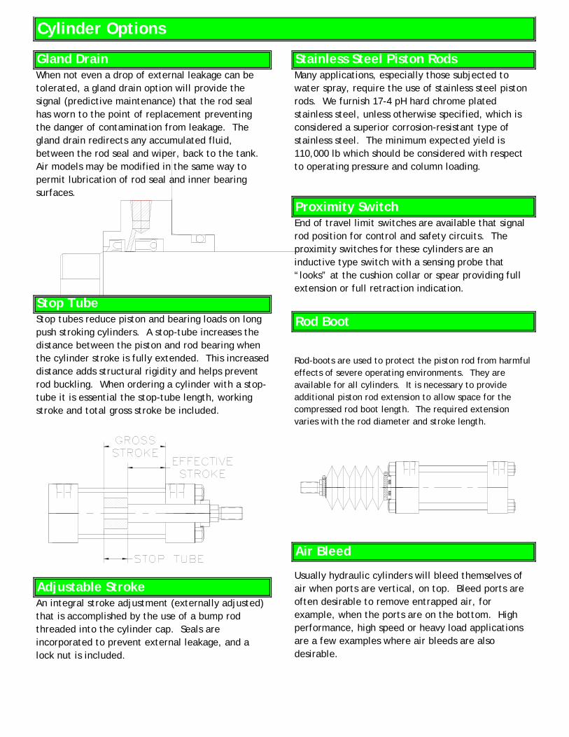
Stop TubeStop tubes reduce piston and bearing loads on long push stroking cylinders. A stop-tube increases the distance between the piston and rod bearing when
Gland DrainWhen not even a drop of external leakage can be tolerated, a gland drain option will provide the signal (predictive maintenance) that the rod seal has worn to the point of replacement preventing the danger of contamination from leakage. The gland drain redirects any accumulated fluid, between the rod seal and wiper, back to the tank. Air models may be modified in the same way to permit lubrication of rod seal and inner bearing surfaces.
Stainless Steel Piston RodsMany applications, especially those subjected to water spray, require the use of stainless steel piston rods. We furnish 17-4 pH hard chrome plated stainless steel, unless otherwise specified, which is considered a superior corrosion-resistant type of stainless steel. The minimum expected yield is 110,000 lb which should be considered with respect to operating pressure and column loading.
Proximity SwitchEnd of travel limit switches are available that signal rod position for control and safety circuits. The proximity switches for these cylinders are an inductive type switch with a sensing probe that “looks” at the cushion collar or spear providing full extension or full retraction indication.
Rod Boot
Air Bleed
Adjustable Stroke
distance between the piston and rod bearing when the cylinder stroke is fully extended. This increased distance adds structural rigidity and helps prevent rod buckling. When ordering a cylinder with a stop-tube it is essential the stop-tube length, working stroke and total gross stroke be included.
Usually hydraulic cylinders will bleed themselves of air when ports are vertical, on top. Bleed ports are often desirable to remove entrapped air, for example, when the ports are on the bottom. High performance, high speed or heavy load applications are a few examples where air bleeds are also desirable.
An integral stroke adjustment (externally adjusted) that is accomplished by the use of a bump rod threaded into the cylinder cap. Seals are incorporated to prevent external leakage, and a lock nut is included.
Rod-boots are used to protect the piston rod from harmful effects of severe operating environments. They are available for all cylinders. It is necessary to provide additional piston rod extension to allow space for the compressed rod boot length. The required extension varies with the rod diameter and stroke length.
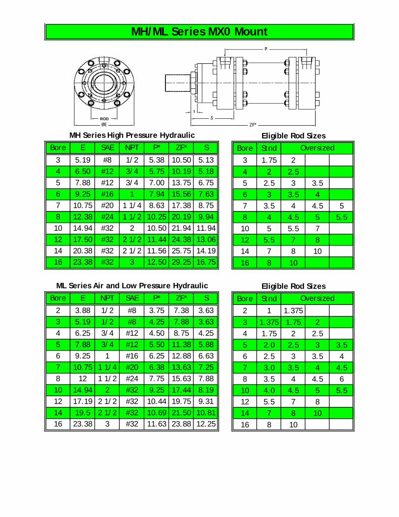
Bore E SAE NPT P* ZF* S Bore Stnd
3 5.19 #8 1/2 5.38 10.50 5.13 3 1.75 24 6.50 #12 3/4 5.75 10.19 5.18 4 2 2.55 7.88 #12 3/4 7.00 13.75 6.75 5 2.5 3 3.56 9.25 #16 1 7.94 15.56 7.63 6 3 3.5 47 10.75 #20 1 1/4 8.63 17.38 8.75 7 3.5 4 4.5 58 12.38 #24 1 1/2 10.25 20.19 9.94 8 4 4.5 5 5.510 14.94 #32 2 10.50 21.94 11.94 10 5 5.5 712 17.50 #32 2 1/2 11.44 24.38 13.06 12 5 5 7 8
MH/ML Series MX0 Mount
MH Series High Pressure Hydraulic Eligible Rod SizesOversized
ROD
12 17.50 #32 2 1/2 11.44 24.38 13.06 12 5.5 7 814 20.38 #32 2 1/2 11.56 25.75 14.19 14 7 8 1016 23.38 #32 3 12.50 29.25 16.75 16 8 10
Bore E NPT SAE P* ZF* S Bore Stnd
2 3.88 1/2 #8 3.75 7.38 3.63 2 1 1.3753 5.19 1/2 #8 4.25 7.88 3.63 3 1.375 1.75 24 6.25 3/4 #12 4.50 8.75 4.25 4 1.75 2 2.55 7.88 3/4 #12 5.50 11.38 5.88 5 2.0 2.5 3 3.56 9.25 1 #16 6.25 12.88 6.63 6 2.5 3 3.5 47 10.75 1 1/4 #20 6.38 13.63 7.25 7 3.0 3.5 4 4.58 12 1 1/2 #24 7.75 15.63 7.88 8 3.5 4 4.5 610 14.94 2 #32 9.25 17.44 8.19 10 4.0 4.5 5 5.512 17.19 2 1/2 #32 10.44 19.75 9.31 12 5.5 7 814 19.5 2 1/2 #32 10.69 21.50 10.81 14 7 8 1016 23.38 3 #32 11.63 23.88 12.25 16 8 10
Oversized
ML Series Air and Low Pressure Hydraulic Eligible Rod Sizes

Bore E SAE NPT P* XC* S M CD L CW CB Bore Stnd
3 5.19 #8 1/2 5.38 12.00 5.13 1.00 1.00 1.50 0.75 1.50 3 1.75 24 6.50 #12 3/4 5.75 13.06 5.19 1.38 1.38 2.13 1.00 2.00 4 2 2.55 7.88 #12 3/4 7.00 16.00 6.75 1.75 1.75 2.25 1.25 2.50 5 2.5 3 3.56 9.25 #16 1 7.94 18.06 7.63 2.00 2.00 2.50 1.25 2.50 6 3 3.5 47 10.75 #20 1 1/4 8.63 20.38 8.75 2.50 2.50 3.00 1.50 3.00 7 3.5 4 4.5 58 12.38 #24 1 1/2 10.25 23.44 9.94 3.00 3.00 3.25 1.50 3.00 8 4 4.5 5 5.510 14.94 #32 2 10.50 26.44 11.94 3.50 3.50 4.00 2.00 4.00 10 5 5.5 712 17.50 #32 2 1/2 11.31 28.88 13.06 4.00 4.00 4.50 2.25 4.50 12 5.5 7 814 20.38 #32 2 1/2 11.56 31.50 14.19 5.00 5.00 5.75 3.00 6.00 14 7 8 10
MH/ML Series MP1 Mount
MH Series High Pressure Hydraulic Eligible Rod SizesOversized
16 23.38 #32 3 12.50 36.25 16.75 6.00 6.00 7.00 3.50 7.00 16 8 10
Bore E NPT SAE P* XC* S M CD L CW CB Bore Stnd
2 3.88 1/2 #8 3.75 8.63 3.63 0.75 0.75 1.25 0.63 1.25 2 1 1.383 5.19 1/2 #8 4.25 9.38 3.63 1.00 1.00 1.50 0.75 1.50 3 1.375 1.75 24 6.25 3/4 #12 4.50 10.88 4.25 1.38 1.38 2.12 1.00 2.00 4 1.75 2 2.55 7.88 3/4 #12 5.50 13.63 5.88 1.75 1.75 2.25 1.25 2.50 5 2.0 2.5 3 3.56 9.25 1 #16 6.25 15.38 6.63 2.00 2.00 2.50 1.25 2.50 6 2.5 3 3.5 47 10.75 1 1/4 #20 6.38 16.63 7.25 2.50 2.50 3.00 1.50 3.00 7 3.0 3.5 4 4.58 12 1 1/2 #24 7.75 18.88 7.88 3.00 3.00 3.25 1.50 3.00 8 3.5 4 4.5 610 14.94 2 #32 9.25 21.44 8.19 3.50 3.50 4.00 2.00 4.00 10 4.0 4.5 5 5.512 17.19 2 1/2 #32 10.44 24.25 9.31 4.00 4.00 4.50 2.25 4.50 12 5.5 7 814 19.5 2 1/2 #32 10.69 27.25 10.81 5.00 5.00 5.75 3.00 6.00 14 7 8 1016 23.38 3 #32 11.63 30.88 12.25 6.00 6.00 7.00 3.50 7.00 16 8 10
Oversized
ML Series Air and Low Pressure Hydraulic Eligible Rod Sizes

Bore E SAE NPT P* XC* S M CD L CK Bore Stnd
3 5.19 #8 1/2 5.38 12.00 5.13 1.63 1.00 1.50 1.00 3 1.75 24 6.50 #12 3/4 5.75 13.06 5.19 1.75 1.38 2.13 1.50 4 2 2.55 7.88 #12 3/4 7.00 16.00 6.75 2.50 1.75 2.25 1.75 5 2.5 3 3.56 9.25 #16 1 7.94 18.06 7.63 2.88 2.00 2.50 2.00 6 3 3.5 47 10.75 #20 1 1/4 8.63 20.38 8.75 3.38 2.50 3.00 2.50 7 3.5 4 4.5 58 12.38 #24 1 1/2 10.25 23.44 9.94 3.88 3.00 3.25 3.00 8 4 4.5 5 5.510 14.94 #32 2 10.50 26.44 11.94 5.50 3.50 4.00 3.19 10 5 5.5 712 17.50 #32 2 1/2 11.31 28.88 13.06 6.00 4.00 4.50 3.50 12 5.5 7 8
MH/ML Series MPU3 Mount
MH Series High Pressure Hydraulic Eligible Rod SizesOversized
14 20.38 #32 2 1/2 11.56 31.50 14.19 6.75 5.00 5.75 4.25 14 7 8 1016 23.38 #32 3 12.50 36.25 16.75 7.50 6.00 7.00 4.63 16 8 10
Bore E NPT SAE P* XC* S M CD L CK Bore Stnd
2 3.88 1/2 #8 3.75 8.63 3.63 1.25 0.75 1.25 0.56 2 1 1.3753 5.19 1/2 #8 4.25 9.38 3.63 1.63 1.00 1.50 1.00 3 1.375 1.75 24 6.25 3/4 #12 4.50 10.88 4.25 1.75 1.38 2.13 1.50 4 1.75 2 2.55 7.88 3/4 #12 5.50 13.63 5.88 2.50 1.75 2.25 1.75 5 2.0 2.5 3 3.56 9.25 1 #16 6.25 15.38 6.63 2.88 2.00 2.50 2.00 6 2.5 3 3.5 47 10.75 1 1/4 #20 6.38 16.63 7.25 3.38 2.50 3.00 2.50 7 3.0 3.5 4 4.58 12 1 1/2 #24 7.75 18.88 7.88 3.88 3.00 3.25 3.00 8 3.5 4 4.5 610 14.94 2 #32 9.25 21.44 8.19 5.50 3.50 4.00 3.19 10 4.0 4.5 5 5.512 17.19 2 1/2 #32 10.44 24.25 9.31 6.00 4.00 4.50 3.50 12 5.5 7 814 19.5 2 1/2 #32 10.69 27.25 10.81 5.75 5.00 5.75 4.25 14 7 8 1016 23.38 3 #32 11.63 30.88 12.25 7.50 6.00 7.00 4.63 16 8 10
Oversized
ML Series Air and Low Pressure Hydraulic Eligible Rod Sizes

Bore E SAE NPT P* ZF* F FB R TE UF BD WA Bore Stnd
3 5.19 #8 1/2 5.4 10.5 1.6 0.6 4.2 5.8 6.8 5.2 3.5 3 1.75 24 6.50 #12 3/4 5.8 10.2 1.6 0.7 5.3 7.2 8.4 6.3 3.6 4 2 2.55 7.88 #12 3/4 7.0 13.8 2.1 0.8 6.4 8.7 10.2 7.9 4.6 5 2.5 3 3.56 9.25 #16 1 7.9 15.6 2.5 1.1 7.3 10.3 12.3 9.3 5.1 6 3 3.5 47 10.75 #20 1 1/4 8.6 17.4 2.5 1.2 8.5 11.9 14.2 10.8 6.3 7 3.5 4 4.5 58 12.38 #24 1 1/2 10.3 20.2 3.4 1.3 9.9 13.7 16.2 12.0 6.6 8 4 4.5 5 5.510 14.94 #32 2 10.5 21.9 3.4 1.6 11.9 16.5 19.5 14.9 8.6 10 5 5.5 712 17.50 #32 2 1/2 11.3 24.4 3.7 1.8 14.0 19.3 22.8 17.2 9.4 12 5.5 7 814 20.38 #32 2 1/2 11.6 25.8 3.7 2.1 16.4 22.4 26.4 19.5 10.5 14 7 8 10
MH/ML Series MF1 Mount
MH Series High Pressure Hydraulic Eligible Rod SizesOversized
14 20.38 #32 2 1/2 11.6 25.8 3.7 2.1 16.4 22.4 26.4 19.5 10.5 14 7 8 1016 23.38 #32 3 12.5 29.3 4.1 2.3 18.9 25.7 30.2 23.0 12.6 16 8 10
Bore E NPT SAE P* ZF* F FB R TE UF BD WA Bore Stnd
2 3.88 1/2 #8 3.8 7.4 1.5 0.4 3.1 4.3 5.0 3.9 2.1 2 1 1.3753 5.19 1/2 #8 4.3 7.9 1.6 0.6 4.2 5.8 6.8 5.2 2.0 3 1.375 1.75 24 6.25 3/4 #12 4.5 8.8 1.6 0.7 5.0 6.9 8.2 6.3 2.6 4 1.75 2 2.55 7.88 3/4 #12 5.5 11.4 2.1 0.8 6.4 8.7 10.2 7.9 3.8 5 2.0 2.5 3 3.56 9.25 1 #16 6.3 12.9 2.5 1.1 7.3 10.3 12.3 9.3 4.1 6 2.5 3 3.5 47 10.75 1 1/4 #20 6.4 13.6 2.5 1.2 8.4 11.9 14.2 10.8 4.8 7 3.0 3.5 4 4.58 12 1 1/2 #24 7.8 15.6 3.4 1.3 9.5 13.9 15.8 12.0 4.5 8 3.5 4 4.5 610 14.94 2 #32 9.3 17.4 3.4 1.6 11.9 16.5 19.5 14.9 4.8 10 4.0 4.5 5 5.512 17.19 2 1/2 #32 10.4 19.8 3.7 1.8 13.7 19.0 22.5 17.2 5.6 12 5.5 7 814 19.5 2 1/2 #32 10.7 21.5 3.7 2.1 15.5 21.6 25.6 19.5 7.1 14 7 8 1016 23.38 3 #32 11.2 23.9 4.1 2.3 18.9 25.7 30.2 23.0 8.1 16 8 10
Oversized
ML Series Air and Low Pressure Hydraulic Eligible Rod Sizes

Bore E SAE NPT P* ZF* F FB R TE UF BD S Bore Stnd
3 5.19 #8 1/2 5.4 10.5 1.6 0.6 4.2 5.8 6.8 5.2 5.1 3 1.75 24 6.50 #12 3/4 5.8 10.2 1.6 0.7 5.3 7.2 8.4 6.3 5.2 4 2 2.55 7.88 #12 3/4 7.0 13.8 2.1 0.8 0.4 8.7 10.2 7.9 6.8 5 2.5 3 3.56 9.25 #16 1 7.9 15.6 2.5 1.1 7.3 10.3 12.3 9.3 7.6 6 3 3.5 47 10.75 #20 1 1/4 8.6 17.4 2.5 1.2 8.5 11.9 14.2 10.8 8.8 7 3.5 4 4.5 58 12.38 #24 1 1/2 10.3 20.2 3.4 1.3 9.9 13.7 16.2 12.0 9.9 8 4 4.5 5 5.510 14.94 #32 2 10.5 21.9 3.4 1.6 11.9 16.5 19.5 14.9 11.9 10 5 5.5 712 17 50 #32 2 1/2 11 3 24 4 3 7 1 8 14 0 19 3 22 8 17 2 13 1 12 5 5 7 8
MH Series High Pressure Hydraulic
MH/ML Series MF2 Mount
Eligible Rod SizesOversized
12 17.50 #32 2 1/2 11.3 24.4 3.7 1.8 14.0 19.3 22.8 17.2 13.1 12 5.5 7 814 20.38 #32 2 1/2 11.6 25.8 3.7 2.1 16.4 22.4 26.4 19.5 14.2 14 7 8 1016 23.38 #32 3 12.5 29.3 4.1 2.3 18.9 25.7 30.2 23.0 16.8 16 8 10
Bore E NPT SAE P* ZF* F FB R TE UF BD S Bore Stnd
2 3.88 1/2 #8 3.8 7.4 1.5 0.4 3.1 4.3 5.0 3.9 3.6 2 1 1.3753 5.19 1/2 #8 4.3 7.9 1.6 0.6 4.2 5.8 6.8 5.2 3.6 3 1.375 1.75 24 6.25 3/4 #12 4.5 8.8 1.6 0.7 5.0 6.9 8.2 6.3 4.3 4 1.75 2 2.55 7.88 3/4 #12 5.5 11.4 2.1 0.8 6.4 8.7 10.2 7.9 5.9 5 2.0 2.5 3 3.56 9.25 1 #16 6.3 12.9 2.5 1.1 7.3 10.3 12.3 9.3 6.6 6 2.5 3 3.5 47 10.75 1 1/4 #20 6.4 13.6 2.5 1.2 8.4 11.9 14.2 10.8 7.3 7 3.0 3.5 4 4.58 12 1 1/2 #24 7.8 15.6 3.4 1.3 9.5 13.9 15.8 12.0 7.9 8 3.5 4 4.5 610 14.94 2 #32 9.3 17.4 3.4 1.6 11.9 16.5 19.5 14.9 8.2 10 4.0 4.5 5 5.512 17.19 2 1/2 #32 10.4 19.8 3.7 1.8 13.7 19.0 22.5 17.2 9.3 12 5.5 7 814 19.5 2 1/2 #32 10.7 21.5 3.7 2.1 15.5 21.6 25.6 19.5 10.8 14 7 8 1016 23.38 3 #32 11.2 23.9 4.1 2.3 18.9 25.7 30.2 23.0 12.3 16 8 10
Oversized
ML Series Air and Low Pressure Hydraulic Eligible Rod Sizes
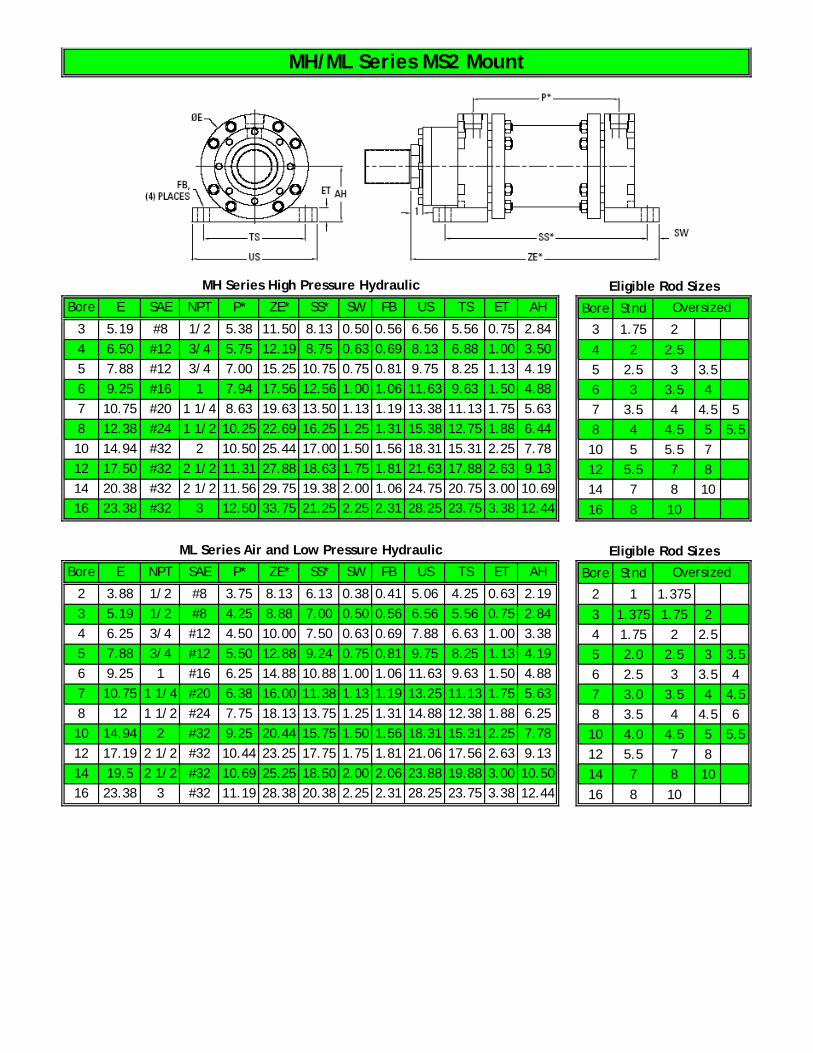
Bore E SAE NPT P* ZE* SS* SW FB US TS ET AH Bore Stnd
3 5.19 #8 1/2 5.38 11.50 8.13 0.50 0.56 6.56 5.56 0.75 2.84 3 1.75 24 6.50 #12 3/4 5.75 12.19 8.75 0.63 0.69 8.13 6.88 1.00 3.50 4 2 2.55 7.88 #12 3/4 7.00 15.25 10.75 0.75 0.81 9.75 8.25 1.13 4.19 5 2.5 3 3.56 9.25 #16 1 7.94 17.56 12.56 1.00 1.06 11.63 9.63 1.50 4.88 6 3 3.5 47 10.75 #20 1 1/4 8.63 19.63 13.50 1.13 1.19 13.38 11.13 1.75 5.63 7 3.5 4 4.5 58 12.38 #24 1 1/2 10.25 22.69 16.25 1.25 1.31 15.38 12.75 1.88 6.44 8 4 4.5 5 5.510 14.94 #32 2 10.50 25.44 17.00 1.50 1.56 18.31 15.31 2.25 7.78 10 5 5.5 712 17.50 #32 2 1/2 11.31 27.88 18.63 1.75 1.81 21.63 17.88 2.63 9.13 12 5.5 7 814 20.38 #32 2 1/2 11.56 29.75 19.38 2.00 1.06 24.75 20.75 3.00 10.69 14 7 8 10
MH/ML Series MS2 Mount
MH Series High Pressure Hydraulic Eligible Rod Sizes
Oversized
14 20.38 #32 2 1/2 11.56 29.75 19.38 2.00 1.06 24.75 20.75 3.00 10.69 14 7 8 1016 23.38 #32 3 12.50 33.75 21.25 2.25 2.31 28.25 23.75 3.38 12.44 16 8 10
Bore E NPT SAE P* ZE* SS* SW FB US TS ET AH Bore Stnd
2 3.88 1/2 #8 3.75 8.13 6.13 0.38 0.41 5.06 4.25 0.63 2.19 2 1 1.3753 5.19 1/2 #8 4.25 8.88 7.00 0.50 0.56 6.56 5.56 0.75 2.84 3 1.375 1.75 24 6.25 3/4 #12 4.50 10.00 7.50 0.63 0.69 7.88 6.63 1.00 3.38 4 1.75 2 2.55 7.88 3/4 #12 5.50 12.88 9.24 0.75 0.81 9.75 8.25 1.13 4.19 5 2.0 2.5 3 3.56 9.25 1 #16 6.25 14.88 10.88 1.00 1.06 11.63 9.63 1.50 4.88 6 2.5 3 3.5 47 10.75 1 1/4 #20 6.38 16.00 11.38 1.13 1.19 13.25 11.13 1.75 5.63 7 3.0 3.5 4 4.58 12 1 1/2 #24 7.75 18.13 13.75 1.25 1.31 14.88 12.38 1.88 6.25 8 3.5 4 4.5 610 14.94 2 #32 9.25 20.44 15.75 1.50 1.56 18.31 15.31 2.25 7.78 10 4.0 4.5 5 5.512 17.19 2 1/2 #32 10.44 23.25 17.75 1.75 1.81 21.06 17.56 2.63 9.13 12 5.5 7 814 19.5 2 1/2 #32 10.69 25.25 18.50 2.00 2.06 23.88 19.88 3.00 10.50 14 7 8 1016 23.38 3 #32 11.19 28.38 20.38 2.25 2.31 28.25 23.75 3.38 12.44 16 8 10
Oversized
ML Series Air and Low Pressure Hydraulic Eligible Rod Sizes

Bore E SAE NPT P* ZF* S TM TL TD Bore Stnd
3 5.19 #8 1/2 5.38 10.50 5.13 5.25 1.50 1.50 3 1.75 24 6.50 #12 3/4 5.75 10.81 5.19 6.56 1.75 1.75 4 2 2.55 7.88 #12 3/4 7.00 13.75 6.75 7.94 2.25 2.25 5 2.5 3 3.56 9.25 #16 1 7.94 15.56 7.63 9.31 2.50 2.50 6 3 3.5 47 10.75 #20 1 1/4 8.63 17.38 8.75 10.81 3.00 3.00 7 3.5 4 4.5 58 12.38 #24 1 1/2 10.25 20.19 9.94 12.44 3.50 3.50 8 4 4.5 5 5.510 14.94 #32 2 10.50 21.94 11.94 15.00 4.00 4.00 10 5 5.5 712 17.50 #32 2 1/2 11.31 24.38 13.06 17.56 5.00 5.00 12 5.5 7 8
MH/ML Series MT4 Mount
MH Series High Pressure Hydraulic Eligible Rod SizesOversized
14 20.38 #32 2 1/2 11.56 25.75 14.19 20.44 5.50 5.50 14 7 8 1016 23.38 #32 3 12.50 29.25 16.75 23.44 6.50 6.50 16 8 10
Bore E NPT SAE P* ZF* S TM TL TD Bore Stnd
2 3.88 1/2 #8 3.75 7.38 3.63 3.94 1.25 1.25 2 1 1.383 5.19 1/2 #8 4.25 7.88 3.63 5.25 1.38 1.38 3 1.375 1.75 24 6.25 3/4 #12 4.50 8.75 4.25 6.31 1.75 1.75 4 1.75 2 2.55 7.88 3/4 #12 5.50 11.38 5.88 7.94 2.00 2.00 5 2.0 2.5 3 3.56 9.25 1 #16 6.25 12.88 6.63 9.94 2.25 2.25 6 2.5 3 3.5 47 10.75 1 1/4 #20 6.38 13.63 7.25 10.81 2.38 2.38 7 3.0 3.5 4 4.58 12 1 1/2 #24 7.75 15.63 7.88 12.06 2.50 2.50 8 3.5 4 4.5 610 14.94 2 #32 9.25 17.44 8.19 15.00 3.00 3.00 10 4.0 4.5 5 5.512 17.19 2 1/2 #32 10.44 19.75 9.31 17.25 3.50 3.50 12 5.5 7 814 19.5 2 1/2 #32 10.69 21.50 10.81 19.56 4.50 4.50 14 7 8 1016 23.38 3 #32 11.19 23.88 12.25 23.44 5.00 5.00 16 8 10
Oversized
ML Series Air and Low Pressure Hydraulic Eligible Rod Sizes

Rod ClevisPart No Rod Dia KK CD CB CW CE A ER
RC044 5/8 7/16-20 0.50 0.77 0.50 1.50 0.75 0.50RC050 5/8 1/2-20 0.50 0.77 0.50 1.50 0.75 0.50RC075 1 3/4-16 0.75 1.27 0.63 2.38 1.13 0.75RC087 1 7/8-14 1.00 1.52 0.75 2.94 1.63 1.00RC100 1 3/8 1-14 1.00 1.52 0.75 3.13 1.63 1.00RC125 1 3/8 1 1/4-12 1.38 2.03 1.00 4.13 2.00 1.38RC150 2 1 1/2-12 1.75 2.53 1.25 4.50 2.25 1.75RC175 2 1 3/4-12 2.00 2.53 1.25 5.50 3.00 2.00RC187 2 1/2 1 7/8-12 2.00 2.53 1.25 5.50 3.00 2.00RC225 3 2 1/4-12 2.50 3.03 1.50 6.50 3.50 2.50RC250 3 1/2 2 1/2-12 3.00 3.03 1.50 6.75 3.50 2.75RC275 4 3-12 3.50 4.03 2.00 8.50 4.50 3.50RC325 4 1/2 3 1/4-12 3.50 4.03 2.00 8.50 4.50 3.50RC350 5 3 1/2-12 3.50 4.03 2.00 8.50 4.50 3.50RC400 5 1/2 4-12 4.00 4.53 2.25 10.00 5.50 4.00
Rod EyePart No Rod Dia KK CD CB CA A ER
FE044 5/8 7/16-20 0.50 0.75 1.50 0.75 0.63FE050 5/8 1/2-20 0.50 0.75 1.50 0.75 0.63
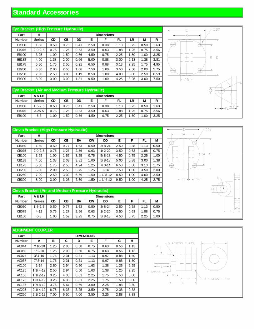
Standard Accessories
FE075 1 3/4-16 0.75 1.25 2.06 1.13 0.88FE087 1 7/8-14 1.00 1.50 2.38 1.13 1.44FE100 1 1-14 1.00 1.50 2.81 1.63 1.19FE125 1 3/8 1 1/4-12 1.38 2.00 3.44 2.00 1.56FE150 1 3/4 1 1/2-12 1.75 2.50 4.00 2.25 2.00FE175 2 1 3/4-12 2.00 2.50 4.38 2.25 2.88FE187 2 1/2 1 7/8-12 2.00 2.50 5.00 3.00 2.50FE225 2 1/2 2 1/4-12 2.50 3.00 5.81 3.50 2.81FE250 3 1/2 2 1/2-12 3.00 3.00 6.13 3.50 3.25FE275 4 3-12 3.50 4.00 7.63 4.50 3.88FE325 4 1/2 3 1/4-12 3.50 4.00 7.63 4.50 3.88FE350 5 3 1/2-12 3.50 4.00 7.63 5.00 3.88FE400 5 1/2 4-12 4.00 4.50 9.13 5.50 4.44
Pivot PinPart No. CL CD A D E CL B
PP050 1.88 0.50 0.47 0.04 0.11 1.88 2.09PP075 2.63 0.75 0.70 0.05 0.13 2.63 2.88PP100 3.13 1.00 0.94 0.05 0.13 3.13 3.38PP138 4.19 1.38 1.29 0.06 0.15 4.19 4.49PP175 5.19 1.75 1.65 0.07 0.18 5.19 5.55PP200 5.19 2.00 1.89 0.09 0.22 5.19 5.55PP250 6.19 2.50 2.36 0.10 0.27 6.19 6.63PP300 6.25 3.00 2.84 0.12 0.36 6.25 6.78PP350 8.13 3.50 3.32 0.12 0.36 8.13 8.85PP400 9.13 4.00 3.79 4.00 4.00 9.13 9.85 Pivot Pin furnished with (2) retainers.
Standard Accessories
Eye Bracket (High Pressure Hydraulic)Part H
Number Series CD CB DD E F FL LR M R
EB050 1.50 0.50 0.75 0.41 2.50 0.38 1.13 0.75 0.50 1.63EB075 2.0-2.5 0.75 1.25 0.53 3.50 0.63 1.88 1.25 0.75 2.56EB100 3.25 1.00 1.50 0.66 4.50 0.75 2.25 1.50 1.00 3.25EB138 4.00 1.38 2.00 0.66 5.00 0.88 3.00 2.13 1.38 3.81EB175 5.00 1.75 2.50 0.91 6.50 0.88 3.13 2.25 1.75 4.95EB200 6.00 2.00 2.50 1.06 7.50 1.00 3.50 2.50 2.00 5.75EB250 7.00 2.50 3.00 1.19 8.50 1.00 4.00 3.00 2.50 6.59EB300 8.00 3.00 3.00 1.31 9.50 1.00 4.25 3.25 3.00 7.50
Eye Bracket (Air and Medium Pressure Hydraulic)Part A & LH
Number Series CD CB DD E F FL LR M R
EB050 1.5-2.5 0.50 0.75 0.41 2.50 0.38 1.13 0.75 0.50 1.63EB075 3.25-5 0.75 1.25 0.53 3.50 0.63 1.88 1.25 0.75 2.56EB100 6-8 1.00 1.50 0.66 4.50 0.75 2.25 1.50 1.00 3.25
Clevis Bracket (High Pressure Hydraulic)Part H
Number Series CD CB BA CW DD E F FL M
CB050 1.50 0.50 0.77 1.63 0.50 3/8-24 2.50 0.38 1.13 0.50CB075 2.0-2.5 0.75 1.27 2.56 0.63 1/2-20 3.50 0.63 1.88 0.75
Dimensions
Dimensions
Dimensions
CB100 3.25 1.00 1.52 3.25 0.75 5/8-18 4.50 0.75 2.25 1.00CB138 4.00 1.38 2.03 3.81 1.00 5/8-18 5.00 0.88 3.00 1.38CB175 5.00 1.75 2.53 4.94 1.25 7/8-14 6.50 0.88 3.13 1.75CB200 6.00 2.00 2.53 5.75 1.25 1-14 7.50 1.00 3.50 2.00CB250 7.00 2.50 3.03 6.59 1.50 1 1/8-12 8.50 1.00 4.00 2.50CB300 8.00 3.00 3.03 7.50 1.50 1 1/4-12 9.50 1.00 4.25 2.75
Clevis Bracket (Air and Medium Pressure Hydraulic)Part A & LH
Number Series CD CB BA CW DD E F FL M
CB050 1.5-2.5 0.50 0.77 1.63 0.50 3/8-24 2.50 0.38 1.13 0.50CB075 4-12 0.75 1.27 2.56 0.63 1/2-20 3.50 0.63 1.88 0.75CB100 6-8 1.00 1.52 3.25 0.75 5/8-18 4.50 0.75 2.25 1.00
ALIGNMENT COUPLERPart
Number A B C D E F G H
AC044 7/16-20 1.25 2.00 0.50 0.75 0.63 0.56 1.13AC050 1/2-20 1.25 2.00 0.50 0.75 0.63 0.56 1.13AC075 3/4-16 1.75 2.31 0.31 1.13 0.97 0.88 1.50AC087 7/8-14 1.75 2.31 0.31 1.13 0.97 0.88 1.50AC100 1-14 2.50 2.94 0.50 1.63 1.38 1.25 2.25AC125 1 1/4-12 2.50 2.94 0.50 1.63 1.38 1.25 2.25AC150 1 1/2-12 3.25 4.38 0.81 2.25 1.75 1.50 3.00AC175 1 3/4-12 3.25 4.38 0.81 2.25 1.75 1.50 3.00AC187 1 7/8-12 3.75 5.44 0.69 3.00 2.25 1.88 3.50AC225 2 1/4-12 6.75 6.38 3.25 3.50 2.75 2.38 2.88AC250 2 1/2-12 7.00 6.50 4.00 3.50 3.25 2.88 3.38
DIMENSIONS
Dimensions

Standard Accessories
SELF-ALIGNING ROD EYE (High Pressure Hydraulic)Part H
Number Series KK A CD CE EX ER LE JL
SAE044 1.50 7/16-20 0.69 0.50 0.88 0.44 0.88 0.75 0.88SAE075 2.0-2.5 3/4-16 1.00 0.75 1.25 0.03 1.25 1.06 1.31SAE100 3.25 1-14 1.50 1.00 1.88 0.88 1.38 1.44 1.50SAE125 4.00 1 1/4-12 2.00 1.38 2.13 1.19 1.81 1.88 2.00SAE150 5.00 1 1/2-12 2.13 1.75 2.50 1.53 2.19 2.13 2.25SAE187 6.00 1 7/8-12 2.88 2.00 2.75 1.75 2.63 2.50 2.75
SELF-ALIGNING ROD EYE (Pneumatic and Low Pressure Hydraulic)Part A & LH
Number Series KK A CD CE EX ER LE JL
SAE044 1.5-2.5 7/16-20 0.69 0.50 0.88 0.44 0.88 0.75 0.88SAE075 3.25-5 3/4-16 1.00 0.75 1.25 0.03 1.25 1.06 1.31SAE100 6-8 1-14 1.50 1.00 1.88 0.88 1.38 1.44 1.50
SELF-ALIGNING CLEVIS BRACKETPart H
Number Series CD E F M R CF CW DD FL
SCB050 1.50 0.50 3.00 0.50 0.50 2.05 0.44 0.50 0.41 1.50SCB075 2.0-2.5 0.75 3.75 0.62 0.88 2.76 0.66 0.62 0.53 2.00SCB100 3.25 1.00 5.50 0.75 1.00 4.10 0.88 0.75 0.53 2.50SCB137 4.00 1.38 6.50 0.88 1.38 4.95 1.19 1.00 0.66 3.50SCB175 5.00 1.75 8.50 1.25 1.75 6.58 1.53 1.25 0.91 4.50SCB200 6.00 2.00 10.62 1.50 2.00 7.92 1.75 1.50 0.91 5.00
DIMENSIONS
DIMENSIONS
DIMENSIONS
SELF-ALIGNING CLEVIS BRACKETPart A & LH
Number Series CD E F M R CF CW DD FL
SCB050 3-12 0.50 3.00 0.50 0.50 2.05 0.44 0.50 0.41 1.50SCB075 3.25-5 0.75 3.75 0.62 0.88 2.76 0.66 0.62 0.53 2.00SCB100 6-8 1.00 5.50 0.75 1.00 4.10 0.88 0.75 0.53 2.50SCB137 4-12 1.38 6.50 0.88 1.38 4.95 1.19 1.00 0.66 3.50SCB175 1.75 8.50 1.25 1.75 6.58 1.53 1.25 0.91 4.50SCB200 2.00 10.62 1.50 2.00 7.92 1.75 1.50 0.91 5.00
SA PIVOT PINSPart H A & LH
Number Series Series CD CL
PP050SA 1.50 1.5-2.5 0.500 1.56PP075SA 2.0-2.5 3.25-5 0.750 2.03PP100SA 3.25 6-8 1.000 2.50
PP138SA 4.00 1.374 3.31
PP175SA 5.00 1.750 4.22PP200SA 6.00 2.000 4.94
Pivot Pin furnished with (2) retainers.
DIMENSIONS
DIMENSIONS
The JIT Certified Guarantee
We guarantee that all cylinders ordered from this catalog will be built to the exact
dimensions specified. All dimensions have been certified to be correct, and thus it is
not necessary to request certified drawings.

Standard Accessories
1. Faster close radial alignment important for long cylinder life 2. Less critical rod end to machine attachment 3. Use with any JIT cylinder with 5/8" or larger rod diameter 4. Use with no extra cost JIT Style 4 rod end 5. Faster cylinder installation and removal 6. Better force distribution on push and pull strokes 7. For use with fixed mount cylinders
Part RodNo. Dia B C D H I J L M N P
SC062 0.63 0.41 1.50 0.56 45o 90o 0.22 4 1.13 0.25 0.66SC100 1.00 0.75 2.00 0.88 30o 60o 0.28 6 1.50 0.38 1.06SC138 1.38 0.94 2.50 1.00 30o 60o 0.34 6 2.00 0.38 1.44SC175 1.75 1.19 3.00 1.25 22.5o 45o 0.34 8 2.38 0.50 1.81SC200 2.00 1.44 3.50 1.63 15o 30o 0.41 12 2.69 0.63 2.06SC250 2.50 1.88 4.00 2.88 15o 30o 0.41 12 3.19 0.75 2.63SC300 3.00 2.38 5.00 2.38 15o 30o 0.53 12 4.00 0.88 3.13SC350 3.50 2.63 5.88 2.63 15o 30o 0.66 12 4.69 1.00 3.63SC400 4.00 3.13 6.38 2.63 15o 30o 0.66 12 5.19 1.00 4.13
Dimensions
Safety CouplerSafety Couplers create a stronger connection than a standard threaded rod end and provide closer radial alignment making installation quicker and results in less wear of component parts by allowing for radial misalignment. Some additional Safety Coupler advantages include:
SC450 4.50 3.63 6.88 3.13 15o 30o 0.66 12 5.69 1.50 4.63SC500 5.00 4.00 7.38 3.13 15o 30o 0.66 12 6.19 1.50 5.13SC550 5.50 4.50 8.25 3.88 15o 30o
0.78 12 6.88 1.88 5.63
Part No. Size E F G H I K L MWP062 0.63 0.50 2.00 0.25 45o 90o 10-24 4 1.13WP100 1.00 0.50 2.50 0.25 30o 60o 1/4-20 6 1.50WP137 1.38 0.63 3.00 0.25 30o 60o 5/16-18 6 2.00WP175 1.75 0.63 4.00 0.25 22.5o 45o 5/16-18 8 2.38WP200 2.00 0.75 4.00 0.38 15o 30o 3/8-16 12 2.69WP250 2.50 0.75 4.50 0.38 15o 30o 3/8-16 12 3.19WP300 3.00 1.00 5.50 0.38 15o 30o 1/2-13 12 4.00WP350 3.50 1.00 7.00 0.38 15o 30o 5/8-11 12 4.69WP400 4.00 1.00 7.00 0.38 15o 30o 5/8-11 12 5.19WP450 4.50 1.00 8.00 0.38 15o 30o 5/8-11 12 5.69WP500 5.00 1.00 8.00 0.38 15o 30o 5/8-11 12 6.19WP550 5.50 1.25 9.00 0.38 15o 30o
3/4-10 12 6.88
Also available as a convenient accessory (optional at extra cost) is a Weld Plate to match each Safety Coupler. The Weld Plate provides the perfect answer to customers who prefer to weld a pre-drilled and tapped, properly sized plate to the machine, rather than laying out, drilling and tapping each hole in the machine. The Weld Plate is equipped with an accurately drilled locator pin hole to facilitate fast, close tolerance positioning. Advantages of our Safety Coupler option include:
Weld Plate

Sealing Solutions and Replacement Seal Kits MH/ML Series
SEAL REPLACEMENT
Polyurethane Custom Sealing Solution
Nitrile
High Pressure Hydraulic Seal Kits Sample
Rod Barrel Standard Viton
Diameter Gland Kit Rod Seal Kit Gland Kit Rod Seal Kit Bore Piston Kit Piston Kit
0.625 KMHG06 KMHR06 KMHGV06 KMHRV06 1.5 KMHP15 KMHPV15
1 KMHG10 KMHR10 KMHGV10 KMHRV10 2 KMHP20 KMHPV20
1.375 KMHG13 KMHR13 KMHGV13 KMHRV13 2.5 KMHP25 KMHPV25
1.75 KMHG17 KMHR17 KMHGV17 KMHRV17 3.25 KMHP32 KMHPV322 KMHG20 KMHR20 KMHGV20 KMHRV20 4 KMHP40 KMHPV40
2.5 KMHG25 KMHR25 KMHGV25 KMHRV25 5 KMHP50 KMHPV50
3 KMHG30 KMHR30 KMHGV30 KMHRV30 6 KMHP60 KMHPV60
3.5 KMHG35 KMHR35 KMHGV35 KMHRV35 7 KMHP70 KMHPV70
4 KMHG40 KMHR40 KMHGV40 KMHRV40 8 KMHP80 KMHPV80
4.5 KMHG45 KMHR45 KMHGV45 KMHRV45
Contents of Standard Seal Kit
Our gland design allows all rod seals, wipers, ‘O’ rings, and back-up washers to be easily removed from every standard gland regardless of rod size. Note that Gland Seal Kits have all seals properly loaded into a JIT Cylinders gland.
Nitrile seals can be supplied for any bore size. The recommended operating temperature range is 10 degrees F.(23 degrees C.) to +165 degrees F. (+74 degrees C).
Viton SealsViton seals can be supplied for any bore size. Viton is suitable for higher temperature requirements within a range of 10 degrees F. (23 degrees C) to +250 degrees F. (+121 degrees C).
JIT Cylinders designs and supplies sealing solutions for the most demanding applications. From exotic operating mediums to extremely high or low temperatures and pressures, we can design and manufacture cylinders that can operate effectively within almost any environment. Contact our engineering department to discuss your unique applications as we strive to supply responsive solutions to solve your application requirements.
Polyurethane seals are standard for H series cylinders.
Piston Seals (2)
Standard Viton
Piston Seal KitRod Seal KitGland Seal Kit
Barrel Seals (2)
Gland O.D. Seal
O.D. Backup
Rod SealRod Wiper
Rod Wiper Gland O.D. SealO.D. Backup
GlandRod Seal

Warranty Service
Warranty
Return Goods Authorization (RGA)
Quality Excellence Policy
100% Tested and Inspected!
In addition, every cylinder is examined for:
Dimensional accuracy. Visual inspection for freedom of defects.Proper unit switch actuation (if applicable). Proper assembly orientation.
Cylinders are first cycled at low pressure to remove air from the system and checked for proper mechanical action. During this procedure rod extension and stroke are measured. Test pressure is applied to cap and head ports in turn and under static pressure all joints are examined for leakage. Air lines are then fitted to cap and head in turn. The hydraulic fitting is removed from the non-pressurized port and a visual inspection made for air bubbles to indicate any piston seal leakage.
We at JIT Cylinders are committed to serving the needs of our customers, as our name implies, Just-In-Time. We are committed to providing products and services which meet application requirements and are engineered for superior performance and reliability. We will achieve this through quality excellence in everything we do. Each task must be performed in conformance to requirements, and systems must be established which assure error-free performance in every area of manufacture. We understand that “quality excellence” depends on the personal performance of each employee. Because of this the entire management team and each member of manufacturing is dedicated and personally involved in the quality improvement process. We are dedicated to a policy of providing quality products and services that fully satisfy our customers’ needs. We subscribe to the following quality absolutes:
We will track our progress in achieving total quality by measuring the price of non-conformance (waste).Our primary objective will be continuous improvement.
Quality is defined as 100 percent conformance to requirements.Our performance goal is to achieve error-free work in all functional areas.Our system for causing quality is prevention.
All returns to JIT Cylinders must be accompanied with a Return Goods Authorization Number. A Return Goods Authorization Number may be obtained by contacting the plant. JIT Cylinders will inquire into why the return is being made and a number will be assigned at that time. Paperwork will be completed by JIT Cylinders giving details of the return from the information supplied by the customer or distributor. At the time the return is received the RGA number will be matched to the proper paperwork. This allows entry of the return without further questions or delays.
JIT Cylinders, Inc. warrants every product of its manufacture to be of proper materials and first class workmanship. We agree to repair or replace, F.O.B. factory, but not to remove or install in the field, any perishable soft goods such as seals, which fail within a six-month period after shipment, normal wear accepted. We warrant for five years from date of shipment, all other parts which fail because of defective materials or workmanship. JIT assumes no responsibility for work done or expenses incurred, in the field, pertaining to such repairs or replacements, except upon written authority from our home office. Components not produced by JIT are subject only to the warranty extended to JIT by their respective manufacturer. When orders have been correctly filled, there shall be no returns without JIT’s approval. Such returns will be subject to a restocking charge.

Theoretical Forces Developed By Cylinders
Push Pull Push Pull Push Pull Push Pull Push Pull Push Pull Push Pull
0.63 1.46 730 1,460 2,190 2,920 4,380 5,840 7,300
1.00 0.98 491 982 1,473 1,964 2,946 3,928 4,910
1.00 2.36 1,180 2,360 3,540 4,720 7,080 9,440 11,800
1.38 1.66 830 1,660 2,490 3,320 4,980 6,640 8,300
1.00 4.12 2,060 4,120 6,180 8,240 12,360 16,480 20,600
1.38 3.43 1,715 3,430 5,145 6,860 10,290 13,720 17,150
1.75 2.51 1,255 2,510 3,765 5,020 7,530 10,040 12,550
1.38 6.82 3,410 6,820 10,230 13,640 20,460 27,280 34,100
1.75 5.90 2,950 5,900 8,850 11,800 17,700 23,600 29,500
2.00 5.16 2,580 5,160 7,740 10,320 15,480 20,640 25,8001.75 10.17 5,085 10,170 15,255 20,340 30,510 40,680 50,850
2.00 9.43 4,715 9,430 14,145 18,860 28,290 37,720 47,150
2.50 7.66 3,830 7,660 11,490 15,320 22,980 30,640 38,300
2.00 16.50 8,250 16,500 24,750 33,000 49,500 66,000 82,500
2.50 14.73 7,365 14,730 22,095 29,460 44,190 58,920 73,650
3.00 12.57 6,285 12,570 18,855 25,140 37,710 50,280 62,850
3 50 10 02 5 010 10 020 15 030 20 040 30 060 40 080 50 100
1.5
2
2.5
3.25
4
5 9,820
18,855 37,710
5,301
9,420
14,730
24,900
Output Forces at Specific Input Pressures
3.14
883 1,767 2,650 3,534
1,570
58,92039,28028,46019,640
3,140 4,710 6,280
8,300
12,570
8.30
4.91 2,455 4,910 7,365 9,820
6,285
4,150
25,140
16,60012,450
12.57
19.64
1.77
2000 PSI1500 PSIRod Dia
Push Area
Pull Area
Forces in Pounds at Various Pressures (PSI)Bore 500 PSI 4000 PSI 5000 PSI1000 PSI 3000 PSI
MH/ML Series
7,068 8,835
50,280 62,850
33,200 41,500
19,640 24,550
12,560 15,700
78,560 98,200
3.50 10.02 5,010 10,020 15,030 20,040 30,060 40,080 50,100
2.50 23.36 11,680 23,360 35,040 46,720 70,080 93,440 116,800
3.00 21.20 10,600 21,200 31,800 42,400 63,600 84,800 106,000
3.50 18.65 9,325 18,650 27,975 37,300 55,950 74,600 93,250
4.00 15.70 7,850 15,700 23,550 31,400 47,100 62,800 78,500
3.00 31.42 15,710 31,420 47,130 62,840 94,260 125,680 157,100
3.50 28.87 14,435 28,870 43,305 57,740 86,610 115,480 144,350
4.00 25.92 12,960 25,920 38,880 51,840 77,760 103,680 129,600
4.50 22.59 11,295 22,590 33,885 45,180 67,770 90,360 112,950
5.00 18.85 9,425 18,850 28,275 37,700 56,550 75,400 94,250
3.50 40.65 20,325 40,650 60,975 81,300 121,950 162,600 203,250
4.00 37.70 18,850 37,700 56,550 75,400 113,100 150,800 188,500
4.50 34.37 17,185 34,370 51,555 68,740 103,110 137,480 171,850
5.00 30.63 15,315 30,630 45,945 61,260 91,890 122,520 153,150
5.50 26.51 13,255 26,510 39,765 53,020 79,530 106,040 132,550
4.50 62.64 31,320 62,640 93,960 125,280 187,920 250,560 313,200
5.00 58.90 29,450 58,900 88,350 117,800 176,700 235,600 294,500
5.50 54.78 27,390 54,780 82,170 109,560 164,340 219,120 273,900
7.00 40.05 20,025 40,050 60,075 80,100 120,150 160,200 200,250
5.50 89.34 44,670 89,340 134,010 178,680 268,020 357,360 446,700
7.00 74.61 37,305 74,610 111,915 149,220 223,830 298,440 373,050
8.00 62.83 31,415 62,835 94,245 125,660 188,490 251,320 314,150
7.00 115.45 57,727 115,454 173,181 230,908 346,361 461,815 577,269
8.00 103.67 51,836 103,673 155,509 207,346 311,018 414,691 518,364
10 00 75 40 37 699 75 398 113 098 150 797 226 195 301 594 376 992
8
6
7
12
14
10
307,877 461,815 615,754 769,692153.9 76,969 153,938 230,908
84,81028.27 14,135 28,270
38.49
42,405 56,540
75,405 100,540 150,810
19,245 38,490 57,735 76,980
39,270 78,540 117,810 157,080 235,620
50.27
115,470
25,135 50,270
113.1 56,550 113,100 169,650 226,200 339,300
78.54
153,960 192,450
113,080 141,350
452,400 565,500
314,160 392,700
201,080 251,350
10.00 75.40 37,699 75,398 113,098 150,797 226,195 301,594 376,992
8.00 150.80 75,398 150,797 226,195 301,594 452,390 603,187 753,984
10.00 122.52 61,261 122,522 183,784 245,045 367,567 490,090 612,612804,250 1,005,31216 201.1 100,531 201,062 301,594 402,125 603,187

• machinists to not ‘cut chips’, but deliver on-time • engineers to not design, but innovate market driven • sales managers to not sell, but offer economical best
Manufacturing Excellence
In keeping pace with tomorrow, JIT Cylinders Research and Development Division believes that distinguishing itself through innovation is an essential factor for continued success. The objective of each project strives to exceed current and future application requirements.
Unequaled Integrity of DesignLeadership in Innovation
Our goal at JIT Cylinders is to achieve best-practice leadership in all processes. From our paperlessmanufacturing floor to our instant 24 hour support, we at JIT Cylinders are in business to serve customersand subscribe to the belief that our success will only follow the success of our customers.
The combination of dedicated, motivated and skilled employees coupled with state-of-the-art automatedequipment and ample manufacturing capacity, results in a competitively priced, high-quality cylinderdelivered on-time to customers worldwide.
• customer service mangers to not answer phones, but service customers
With over a century of manufacturing experience, consistent quality delivered on time is our guarantee.Being a 100% employee-owned company enhances the motivation of every JIT employee. Every employeeunderstands their unique vital role toward earning and retaining long term customers.
JIT Cylinders is an employee owned company that does not make decisions based on stockholder value. Wemake decisions based on what our customer’s value. Our goal is not to simply retain customers, we strive tocontinuously earn our customers by exceeding their expectations in terms of value, service, quality anddelivery. Each day we compete for long term customers and are succeeding by nurturing a corporateculture that encourages and motivates our:
Product quality is further enhanced by our continuing investment in capital equipment. Substantialexpenditures have been made for flexible unmanned machining centers, computers on the manufacturingfloor, CNC and NC machining centers, advanced material handling equipment, and testing stands.
Employee participation in quality-oriented teams also contribute to our quality manufacturing. Teams meetregularly to discuss better, faster, leaner and more economical ways to produce products and streamlinemanufacturing and sales operations. Our customers benefit from an improved product selection that ismanufactured more efficiently.
A commitment to quality engineering, research, and product development remains our principal focus.
Substantial investments are made to strengthen JIT Cylinders high-technology systems capabilities. Key initiatives are focused toward combining electronic controls, and new structural materials with enviromental friendly mediums to improve productivity, energy savings, operator efficiency and comfort.

“At JIT (Just-In-Time) Cylinders,
we supplycylinder solutions for today and tomorrow’s industrial applications. Being 100% employee owned
we workas a unified team to exceed our customers' requirements. Through this motivational approach,
we deliverinnovative and responsive cylinder application solutions. At the same time,
we supportyour engineering, design and manufacturing teams. Though this approach
we buildour leadership and strengthen our business to ensure
we createlong term partnerships.”