Embed Size (px)
Citation preview
João Victor de Figueiredo Leite
3D PRINTING CONTENT WEB VISUALIZATION USING 3MF
B.Sc. Dissertation
Federal University of [email protected]
www.cin.ufpe.br/~graduacao
RECIFE2015

Federal University of Pernambuco
Center for InformaticsB.Sc in Computer Science
João Victor de Figueiredo Leite
3D PRINTING CONTENT WEB VISUALIZATION USING 3MF
A B.Sc. Dissertation presented to the Center for Informatics
of Federal University of Pernambuco in partial fulfillment
of the requirements for the degree of Bachelor in Computer
Science.
Advisor: Veronica Teichrieb
Co-Advisor: João Marcelo Xavier Natário Teixeira
RECIFE2015


I dedicate this thesis to all my family, friends and professors
who gave me the necessary support to get here.


Acknowledgements
To my parents, for the years of support, trust and education. You made me who I am.To my mother, wherever she is right now, for all the care given to me during the years
she was alive.To my sisters, for all the advice and presence on hard times. We will be always supporting
each other.To my friends, for all the times where a bit of friendship helped me relax and forget my
problems.To my advisors Veronica and "Joma", for the opportunity, guidance and effort that made
this work possible.

Resumo
Com o surgimento de novas tecnologias para visualizar informações 3D no navegador,uma tendência pode ser observada no que concerne ao crescente uso de tais tecnologias emaplicações web, tendo em vista que os navegadores atualmente estão presentes em virtualmentequalquer aparelho. Da mesma forma, um crescimento também pode ser observado no campo deimpressão 3D, uma vez que as impressoras estão se tornando mais baratas conforme a tecnologiaevolui. Este estudo tem como objetivo desenvolver um carregador e um visualizador webpara o formato 3MF, e testar seu desempenho em aparelhos desktop e móveis, procurando poruma forma otimizada de mostrar dados de impressão 3D em navegadores. A fim de validar ovisualizador e o carregador, um simulador de impressão 3D também foi implementado e testadoem diferentes plataformas. Constatou-se que o formato 3MF é melhor do que o STL, graçasa suas maiores capacidades, extensibilidade, e até um menor tempo de carregamento dadas asotimizações adequadas.
Palavras-chave: Visualização 3D, Impressão 3D, 3MF, Three.js, CSG, Web

Abstract
With the rise of new technologies for visualizing 3D information in the browser, a trendcan be observed concerning the growing use of such technologies in web-based applications,due to browsers being present in virtually every device. Also, a growth can be observed in the3D printing field, since the printers are becoming cheaper as the technology evolves. This studyaims to develop a loader and a web visualizer for the 3MF format, and test its performance acrossdesktop and mobile devices, searching for an optimized way of displaying 3D printing data inbrowsers. To test the validity of the loader, a 3D printing simulator was also implemented andtested across platforms. It was discovered that 3MF is better than STL for visualizing 3D contenton the web, due to its greater capabilities, extensibility, and even a smaller loading time giventhe right optimizations.
Keywords: 3D Visualization, 3D Printing, 3MF, Three.js, CSG, Web

List of Figures
2.1 CSG operations being applied to a sphere and a cube. . . . . . . . . . . . . . . 222.2 An initial stage of modeling a dice. . . . . . . . . . . . . . . . . . . . . . . . . 222.3 A simple dice modelled with a CSG operation. . . . . . . . . . . . . . . . . . 23
3.1 A simple overview of the architecture up to the asynchronous control. . . . . . 273.2 A simple overview of the architecture, excluding helper functions. . . . . . . . 28
4.1 Intermediary simulation results of the 3D printing process. . . . . . . . . . . . 304.2 The defined parallelepiped intersecting a tetrahedron. . . . . . . . . . . . . . . 31
5.1 Loaded 3MF models. . . . . . . . . . . . . . . . . . . . . . . . . . . . . . . . 33


List of Tables
5.1 File format sizes (in KB). . . . . . . . . . . . . . . . . . . . . . . . . . . . . . 345.2 STL file parsing time (in ms). . . . . . . . . . . . . . . . . . . . . . . . . . . . 355.4 3MF unzipping times (in ms). . . . . . . . . . . . . . . . . . . . . . . . . . . 365.5 3MF parsing times (in ms). . . . . . . . . . . . . . . . . . . . . . . . . . . . . 365.3 Binary STL file parsing time (in ms). . . . . . . . . . . . . . . . . . . . . . . 365.6 Time taken by each loader to unzip files in PC (in ms). . . . . . . . . . . . . . 375.7 Time taken by each loader to parse models in PC (in ms). . . . . . . . . . . . . 385.8 Slicing times (in ms). . . . . . . . . . . . . . . . . . . . . . . . . . . . . . . . 39

Contents
1 Introduction 171.1 Objectives . . . . . . . . . . . . . . . . . . . . . . . . . . . . . . . . . . . . . 171.2 Document Structure . . . . . . . . . . . . . . . . . . . . . . . . . . . . . . . . 18
2 Basic Concepts 192.1 Three Dimensional Visualization . . . . . . . . . . . . . . . . . . . . . . . . . 192.2 Three Dimensional Printing . . . . . . . . . . . . . . . . . . . . . . . . . . . . 202.3 The 3MF File Format . . . . . . . . . . . . . . . . . . . . . . . . . . . . . . . 202.4 CSG . . . . . . . . . . . . . . . . . . . . . . . . . . . . . . . . . . . . . . . . 21
3 ThreeMF Loader 253.1 Three.js . . . . . . . . . . . . . . . . . . . . . . . . . . . . . . . . . . . . . . 253.2 Architecture . . . . . . . . . . . . . . . . . . . . . . . . . . . . . . . . . . . . 26
4 Printing Simulator 294.1 Implementation . . . . . . . . . . . . . . . . . . . . . . . . . . . . . . . . . . 29
5 Results and Analysis 335.1 File Format Comparison . . . . . . . . . . . . . . . . . . . . . . . . . . . . . 335.2 Loading Time . . . . . . . . . . . . . . . . . . . . . . . . . . . . . . . . . . . 345.3 Loaders Comparison . . . . . . . . . . . . . . . . . . . . . . . . . . . . . . . 375.4 Printing Simulator Analysis . . . . . . . . . . . . . . . . . . . . . . . . . . . . 38
6 Conclusion 416.1 Future Work . . . . . . . . . . . . . . . . . . . . . . . . . . . . . . . . . . . . 42
References 43
Appendix 47
A 3MF Specification 49

171717
1Introduction
Lately, new web technologies in the field of 3D graphics have been developed, such asWebGL (1), “Three.js” (2) and Babylon (3), which are enabling a pervasive cross-browser formof processing and displaying graphical data without most of the portability concerns traditionaltechnologies have, leaving only typical cross-browser API differences as a possible problem.These new technologies have already enabled powerful new tools to be developed (4), and theirperformance can be fine-tuned to work well both on desktop and mobile platforms (5).
Currently, those visualization technologies are being explored widely and a myriad ofexamples are available. Many of them are now related to a field that has been gaining attentionin the last years: 3D printing.
3D printing, or additive manufacturing, is the process of transforming informationcontained in a digital three-dimensional object into a physical object. It achieves such feat byextracting horizontal cross-sections of the virtual objects, which are then printed and laid downuntil the whole object is created (6).
Throughout last years the 3D printing technology has risen in popularity, even farther thanwhat was expected according to experts (7). This gave spawn to a series of very differentiatedapplications ranging from manufacturing composite elements (8) to printing biomaterials (9).
However, the file format considered as the de facto standard, STL (Standard TriangulationLanguage) (10)(11)(12), is falling behind since it is limited in its representational capabilities inregard to the constantly evolving technological scenario. Therefore, new initiatives were foundedin order to find a suitable format that can be extended as needed, providing support to emergingtechnologies, such as AMF (Additive Manufacturing Format) (13) and 3MF (3D ManufacturingFormat) (14).
1.1 Objectives
This work aims to study current techniques for web related 3D visualization. Specifically,it first intends to explore the “Three.js” framework (2) and its visualization capabilities, movingforward to the implementation of a 3MF file (14) based web visualizer, and finally test it both on
18 CHAPTER 1. INTRODUCTION
mobile and desktop platforms. The visualizer will be implemented as an open source tool, withthe objective to effectively contribute with the “Three.js” community by adding a new loader toits extensions.
Despite existing other open-source options that also enable web 3D visualization, likeBabylon [39], the “Three.js” framework was chosen because of experience related issues.
Then, implement the horizontal cross-section slicing algorithm used by 3D printers. Thiswill enable the visualizer to simulate the 3D printing process through the progressive assemblyof the visualized object’s slices, effectively validating the loader.
Hence, the specific objectives that this work intends to reach are:
� Implement a web based 3MF visualizer;
� Contribute to the open source community;
� Test the visualizer functionality both on mobile and desktop platforms;
� Simulate the 3D printing process on the visualizer.
1.2 Document Structure
With the intention to present the contents of this work in a suitable way, five chapterswere devised, beyond the current one.
The first one, called Basic Concepts, presents basic concepts involved in the making ofthis work, as well as related themes.
The second chapter discusses the technology and architecture used to implement someof the objectives of this work, which are the 3MF loader named ThreeMF Loader and the webvisualizer. The loader gives name to this chapter.
The third chapter, Printing Simulator, presents the work involved in implementing theprinting simulator, discussing both the challenges encountered and the technologies utilized inits making.
The fourth chapter named Results and Analysis describes the tests made both regardingthe loader and the printing simulator, and also compares the 3MF file format to the STL fileformat, with the objective of ascertaining which would be best suited for web visualization ingeneral.
The fifth and final chapter brings the conclusions of this work, as well as ideas for futurework.
191919
2Basic Concepts
This chapter will discuss the fundamental concepts involved in the execution of thisgraduation project. First, the current 3D visualization technologies will be discussed, with afocus on web visualization. Then, there will be a quick introduction to the additive 3D printingprocess, to the 3MF file format, and to CSG (Constructive Solid Geometry) object representationconcepts that were fundamental to the conclusion of the project.
2.1 Three Dimensional Visualization
For a long time, 3D visualization was a task left to computers with more processingpower on an offline setting. Such fact can be observed due to the fact that well established andefficient technologies for handling 3D scenes such as OpenGL (15) and DirectX (16) are linkedto the installing of specialized software.
However, with the advent of technologies such as WebGL (1) and “Three.js” (2), the useof the web browser for such work is growing, and with the most varied uses (4)(17). A greatadvantage of using a browser oriented approach nowadays is that web browsers are present invirtually every device, from computers to mobile phones.
It must be noticed that, meanwhile those 3D visualization web technologies can be usedin mobile web browsers, presenting such content on mobile devices is considered a challenge(5), even with their growing power.
So, from a developer’s perspective, offering a 3D web visualization tool that worksboth on desktop and mobile platforms brings concerns over efficiency, for the mobile devicemight not be powerful enough to render what is proposed, and the usage of data, since the usercan be restricted by his/her data plan. Also, even if the device is powerful enough to renderintensive graphics, the developer must be concerned with battery usage, or his/her application,be it web or not, can be disfavoured for rapidly discharging an user’s mobile device. In this work,aspects regarding the time to download and data usage will be covered in the tests, as well as theprocessing time required to efficiently load and display models and their printing simulation.
20 CHAPTER 2. BASIC CONCEPTS
2.2 Three Dimensional Printing
Formally, 3D printing is defined as a form of rapid prototyping (18)(19), term whichoriginated from the time saving associated with the negation of the human modeller (19), anddefines a set of technologies used to fabricate physical objects from data generated by computersystems (20).
And, despite being a more modern form of rapid prototyping, the 3D printing processfollows the same principles (19) as other related processes:
1. A 3D model of the desired component is created in CAD (Computer Aided Design)software;
2. The model is translated into a format suitable for its manufacturing, such as STL(Standard Triangulation Language), which is a standard data format that can beused by most machines. This step is useful because it describes the surface of themodel in a manner that enables it to be sliced into layers so that it can be constructedsequentially;
3. Each computed layer (or slice) is then sent to the machine, which uses the informationto build the object.
Major advantages of such 3D printing process when compared to traditional means ofprototyping are the increased complexity of the object that can be built and the faster creation ofreal models (20).
Furthermore, the 3D printing industry is growing rapidly (7), and is expected to groweven further as 3D printers become cheaper and more accessible to everyone. Services such asrenting a 3D printer for a period of time (21) and for mass producing customized items (22)(23)are starting to become common, and the tendency is that this industry will grow far more (24)and change our daily lives (25).
As such, the need of consumers to preview the 3D objects that they will print or orderwill grow, and the most pervasive way of doing such preview is through browsers, which arevery common. So, the need for loaders for various 3D printing can be justified even by industryneeds.
2.3 The 3MF File Format
3MF, or 3D Manufacturing Format, is a new file format designed by the 3MF Consortiumwith the objective of having the following properties: be rich enough to fully describe a 3Dmodel containing all of the desired characteristics; be easily extensible; be interoperable, so itcan be used in a wide range of machines; and, be able to be broadly adopted (14). With that, ithopes to be free of the issues involving other formats, such as the STL (13).
2.4. CSG 21
According to its specification (26), a 3MF file is in fact a zip file that obeys the OpenPackaging Conventions (27). And hence, relationships must be described between the zipfile (called a package) and its different files and folders (called parts). Such relationships aredescribed by XML files that have the name of the file that is the source of the relationship, anddespite being in fact XML files, their extension is .rels. Those files must be inside a _rels folderthat must be located at the same level of the parts whose relationships they describe.
The folder structure at the root of the zip file may have the following folders: 3D(Mandatory), Metadata (Optional) and _rels (Mandatory). The 3D folder contains the 3D modelin a file called 3Dmodel.model, and the optional folders Textures and _rels. Finally, the Texturesfolder holds the 3D models textures as images, if such textures exist.
Besides folders, the root of the zip file also contains a file called [Content_Types].xml,which has the content types for each file extension contained in the 3MF file. For instance, if the3MF file contains JPEG textures inside its Textures folder, the “.jpg” extension and its mimetype will be present in this file.
For this work, the main files to be observed are the 3Dmodel.model and the imagetextures files, because both contain the core of what is necessary to fully display the 3D modelthat the 3MF file represents. It is noteworthy that, like the relationship files, the 3Dmodel.modelfile is, in fact, an XML file. The specification for this XML file possesses several tags, but fromall of them, the most relevant to this work are described in the appendix A.
2.4 CSG
In order to implement a printing simulator, a technique capable of properly executinga 3D model slicing had to be found, for slicing being one of the basic steps that compose3D printing and rapid manufacturing techniques, as cited before. The CSG, or ConstructiveSolid Geometry, was found to be the fastest way to implement such idea, since it is an alreadyestablished technique, and there are several libraries that implement it.
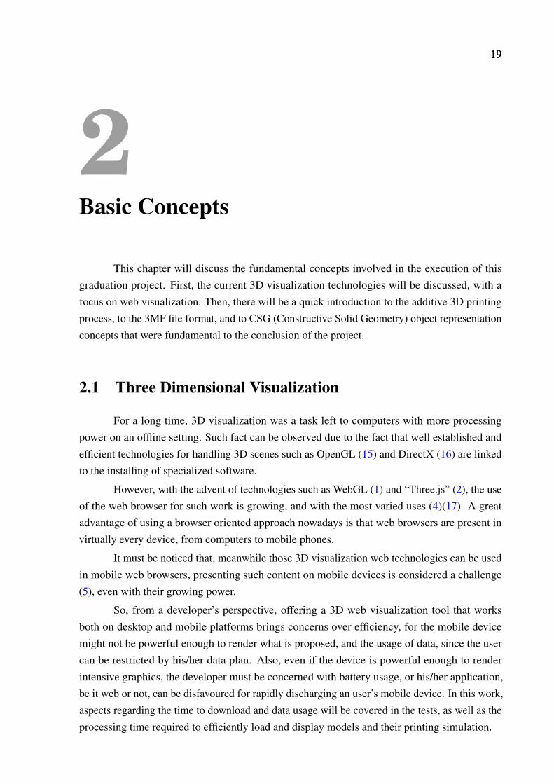
First proposed in a series of papers in 1977 (28), it has a strong theoretical base that hasbeen developed upon the years. It consists of a method of constructing solid models based ona set of primitive solids (e.g. cubes, cylinders, cones) and primitive operations (e.g. set union,intersection or difference) (29). Then, by combining the primitive solids through the defined setof operations, new solids can be made. Figure 2.1 shows the result of combining a cube and asphere through an union, a difference and an intersection operation, building three new solidgeometries.
22 CHAPTER 2. BASIC CONCEPTS
Figure 2.1: CSG operations being applied to a sphere and a cube.
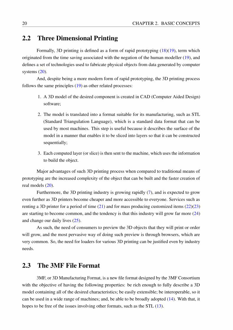
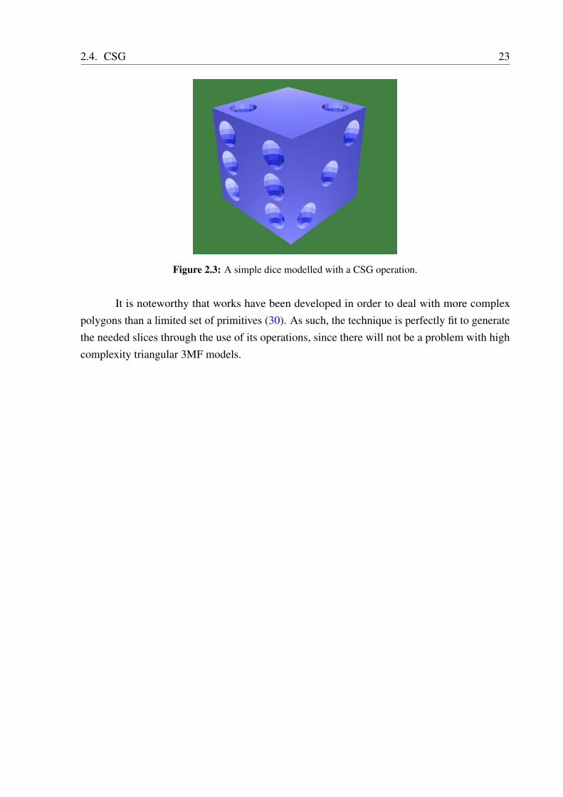
An actual example of modeling with CSG is the steps involved in the making of a simpledice. First, the user can define a cube and place several spheres in the dice’s surface, representingwhere the spherical holes will be (Figure 2.2).
Figure 2.2: An initial stage of modeling a dice.
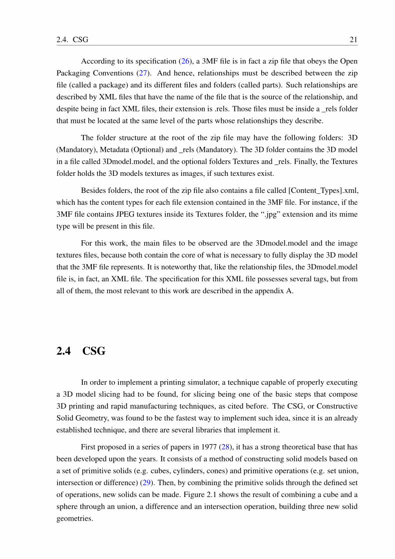
Then, by applying the difference operation, a simple model of a dice can be obtained,since all that the spheres will leave are the desired holes in the dice (Figure 2.3).
2.4. CSG 23
Figure 2.3: A simple dice modelled with a CSG operation.
It is noteworthy that works have been developed in order to deal with more complexpolygons than a limited set of primitives (30). As such, the technique is perfectly fit to generatethe needed slices through the use of its operations, since there will not be a problem with highcomplexity triangular 3MF models.

252525
3ThreeMF Loader
The loader proposed in this work was implemented through the use of the “Three.js”library to parse 3MF files in accord to the specifications (26). In this chapter, there will be abrief introduction to the “Three.js” library and how it was used in the loader, followed by thediscussion of the loader’s architecture.
3.1 Three.js
The “Three.js” is a lightweight 3D library that simplifies the use of 3D graphics inside abrowser (2). It features a simple API and has different options of rendering engines, with thedefault engines being: HTML5 canvas and SVG elements, CSS3D and WebGL. For the purposesof this work, the WebGL renderer was used together with the HTML5 canvas element, so themodels could be rendered to the screen.
Despite being simple, the “Three.js” is quite flexible, and possesses a myriad of objectsthat can be used to represent, animate and deform a given 3D object. Since the objective of thisproject was only to load a 3MF file, only a subset of the classes related to the representation ofan object were used.
The base class for all rendering done in “Three.js” is called Scene, and an instance of suchclass manages the rendering of several models on the screen. Each model must be constructedand added to the scene separately by using one of the provided base classes in “Three.js”.
One of the basic “Three.js” data structures for representing an object is the Geometryclass. It contains all the information about the object’s vertices, faces, colors and texture UVs,and also includes positional information and more advanced properties such as morph options,used to animate an object’s deformation. This class was chosen for being flexible and used inother loaders, so there was already a solid foundation to develop upon.
To use the Geometry class, one must first obtain all of the model vertices and save themat the desired Geometry object. This enables the use of the classes describing the faces of ageometry, for those depend upon a previous reference to a Geometry’s vertices.
The class utilized to describe a Geometry face was the Face3 class. That decision was
26 CHAPTER 3. THREEMF LOADER
based on the fact that such class merely describes a Triangle in space, and the 3MF format storesthe model as a discrete, triangularized mesh. As an added bonus, this class can also define whichcolor the face will have, and which texture that face will use, so it is also robust enough to offerthe full representation needed by the current state of the 3MF format.
It is important to notice that, in order to the face texture to work, the UV mappings foreach vertex have to be defined alongside them, since there must be one UV mapping for eachvertex in a “Three.js” Geometry, even if it effectively maps no texture. Both vertices and UVmappings are stored inside arrays in a Geometry object, called “vertices” and “faceVertexUvs”,respectively.
Outside of the loader, more high level classes were used to describe how the object looks,in specific the Mesh class, which relates a Geometry with the materials that will be used todisplay it. A material defines which shader will be used to render a geometry, and if necessary, atexture that will be rendered using such shader. For this project, the MeshPhongMaterial was theone utilized.
So, by utilizing the classes described before, one can fully describe a triangular mesh,regardless of size, even if such mesh contains more complex information such as color andtextures. For a concrete example about the library’s initialization and object construction, pleaserefer to the source code of this project in Appendix B, and also to the examples at the “Three.js”website.
3.2 Architecture
For the definition of the loader’s architecture, current loaders at the “Three.js” basecode were studied, so a general structure could be identified to construct the ThreeMF Loaderupon it. Such structure indicated the need for a new “Three.js” class, and so a class namedThreeMFLoader was defined inside a new source file, called “ThreeMFLoader.js”.
The loaders found in the “Three.js” code base have their primary function defined inform of a load function, which receives an url and returns a model. But, despite having asimilar signature, some loaders differed when it came to the return type, with some returningfully formed Mesh objects, and others returning Geometries. Considering that the function of aloader should not affect how the loaded model is displayed in the viewer, it was decided that theThreeMFLoader should just return a Geometry and a list of the accompanying 3MF textures,leaving the decisions of which materials should be used to display the model to the loader’s finaluser.
As for the inner workings of the load function, new libraries had to be found, since no“Three.js” loader had to deal with a zipped file at the time this work was done. So, the “zip.js”library(31) was chosen as a means to unzip the 3MF file and obtain its contents. Functionswere then defined to look through the zip file contents and unzip the ones needed, such as the“3Dmodel.model” and the related texture image files. However, the “zip.js” library uses Web
3.2. ARCHITECTURE 27
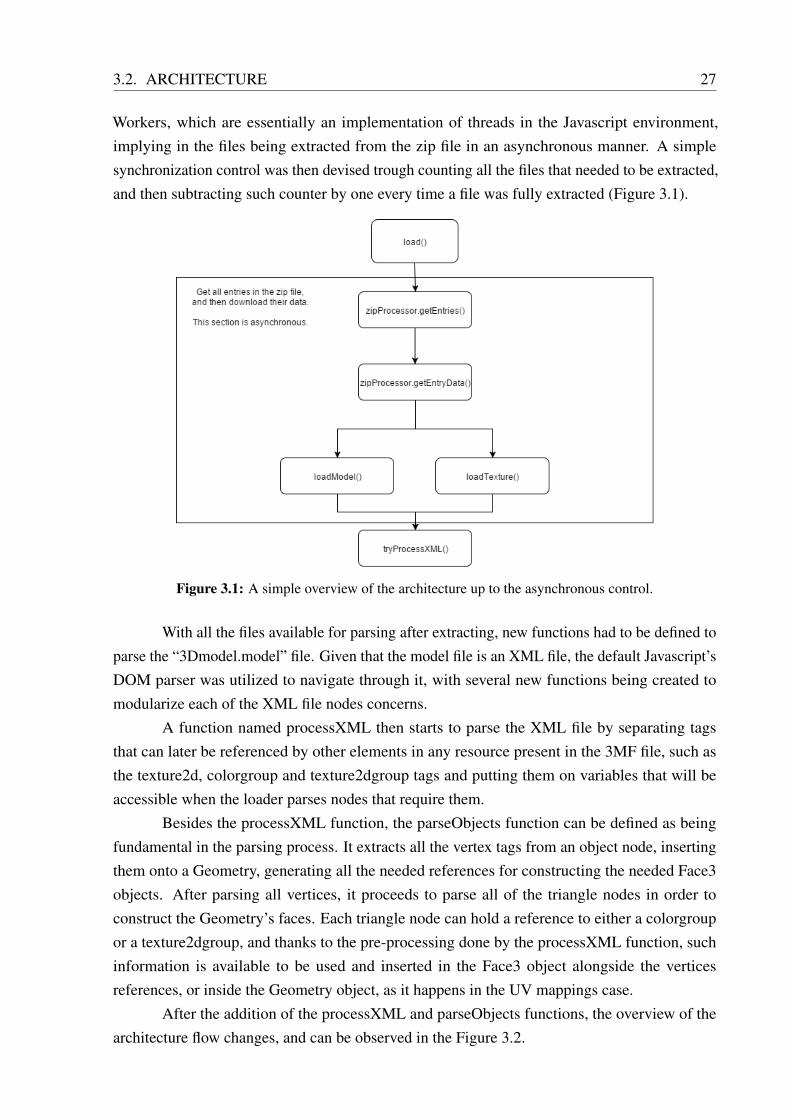
Workers, which are essentially an implementation of threads in the Javascript environment,implying in the files being extracted from the zip file in an asynchronous manner. A simplesynchronization control was then devised trough counting all the files that needed to be extracted,and then subtracting such counter by one every time a file was fully extracted (Figure 3.1).
Figure 3.1: A simple overview of the architecture up to the asynchronous control.
With all the files available for parsing after extracting, new functions had to be defined toparse the “3Dmodel.model” file. Given that the model file is an XML file, the default Javascript’sDOM parser was utilized to navigate through it, with several new functions being created tomodularize each of the XML file nodes concerns.
A function named processXML then starts to parse the XML file by separating tagsthat can later be referenced by other elements in any resource present in the 3MF file, such asthe texture2d, colorgroup and texture2dgroup tags and putting them on variables that will beaccessible when the loader parses nodes that require them.
Besides the processXML function, the parseObjects function can be defined as beingfundamental in the parsing process. It extracts all the vertex tags from an object node, insertingthem onto a Geometry, generating all the needed references for constructing the needed Face3objects. After parsing all vertices, it proceeds to parse all of the triangle nodes in order toconstruct the Geometry’s faces. Each triangle node can hold a reference to either a colorgroupor a texture2dgroup, and thanks to the pre-processing done by the processXML function, suchinformation is available to be used and inserted in the Face3 object alongside the verticesreferences, or inside the Geometry object, as it happens in the UV mappings case.
After the addition of the processXML and parseObjects functions, the overview of thearchitecture flow changes, and can be observed in the Figure 3.2.
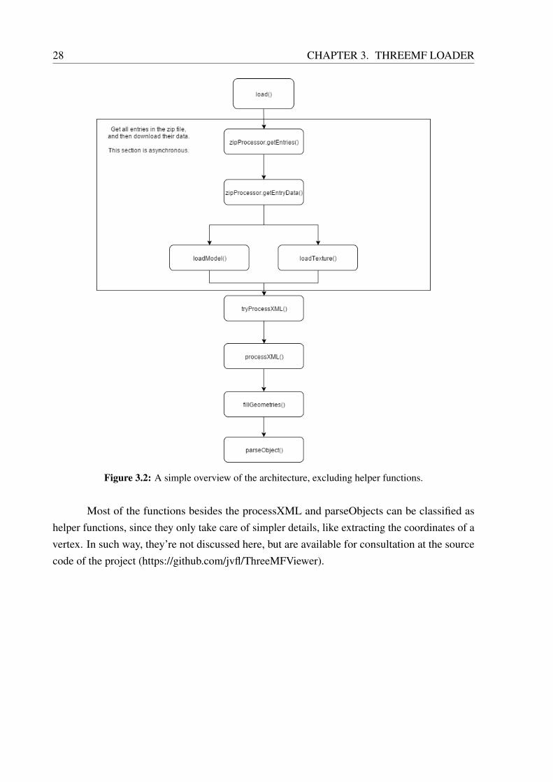
28 CHAPTER 3. THREEMF LOADER
Figure 3.2: A simple overview of the architecture, excluding helper functions.
Most of the functions besides the processXML and parseObjects can be classified ashelper functions, since they only take care of simpler details, like extracting the coordinates of avertex. In such way, they’re not discussed here, but are available for consultation at the sourcecode of the project (https://github.com/jvfl/ThreeMFViewer).
292929
4Printing Simulator
In order to validate the loader usefulness in a real web application, a basic 3D printingsimulator was implemented. This chapter will present the basic implementation details of theSimulator, describing the used libraries and offering a short analysis of the results obtained withthe simulator implementation.
4.1 Implementation
After the model is in the appropriate structure, to simulate the additive manufacturingprocess one has to divide it into layers, effectively slicing it. To achieve the slicing a CSG librarywas utilized, namely the “CSG.js” library (32).
The “CSG.js” library implements CSG boolean operations by using BSP (Binary SpacePartitioning) trees, but at the time of implementation of this work it was severely outdated (32).A suitable updated version was found inside the source code of the OpenJSCad project (33),which enabled the implementation of the slicing feature through the use of CSG’s intersectionoperation.
Despite being an updated version, the “CSG.js” basic data structures differ from the onesfound in “Three.js”, and as such a third component was needed in order to enable inter-operationbetween the libraries; the “ThreeCSG.js” (34) was used to do so. However, in a similar fashionto the “CSG.js” library, that new component was also outdated. Thus, the “ThreeCSG.js” libraryhad to be updated, and so there was the need to better understand the “CSG.js” data structures.
Similarly to “Three.js”, “CSG.js” has a set of classes designed to represent 3D models,from which some were selected based on their properties, that were sometimes analogous tothose found in the chosen “Three.js” data structures. Those are the CSG, Polygon, Vertex andVector3D classes, described as follows:
CSG Represents a 3D model and contains a list of Polygons. Its chosen counterpart in the“Three.js” library is the Geometry class.
Polygon A 3D polygon, represented by a list of vertices. Since it describes a face in the high
30 CHAPTER 4. PRINTING SIMULATOR
level CSG object, this class was used to be the equivalent of a Face3 object, despite beingmore general.
Vertex Represents a single 3D point, and can be directly correlated to a “Three.js” vertex.
Vector3D Required for the construction of a CSG Vertex, it represents a vector or a point in 3Dspace.
In such way, a Polygon could easily be transformed in a Face3 object, and vice-versa,thus effectively bridging both libraries. After updating the “ThreeCSG.js” library, the objectscould be easily converted between CSG and Geometry objects, giving “Three.js” full access tothe “CSG.js” capabilities.
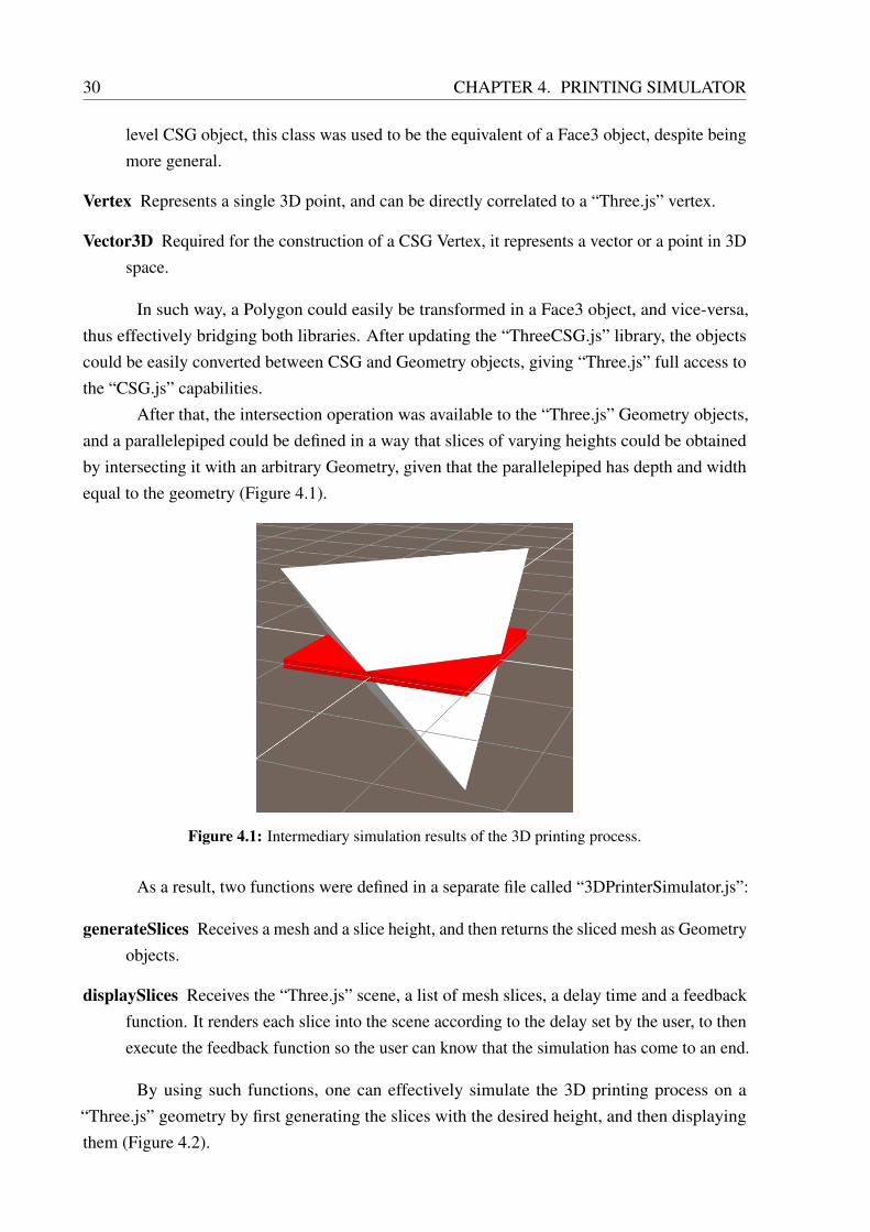
After that, the intersection operation was available to the “Three.js” Geometry objects,and a parallelepiped could be defined in a way that slices of varying heights could be obtainedby intersecting it with an arbitrary Geometry, given that the parallelepiped has depth and widthequal to the geometry (Figure 4.1).
Figure 4.1: Intermediary simulation results of the 3D printing process.
As a result, two functions were defined in a separate file called “3DPrinterSimulator.js”:
generateSlices Receives a mesh and a slice height, and then returns the sliced mesh as Geometryobjects.
displaySlices Receives the “Three.js” scene, a list of mesh slices, a delay time and a feedbackfunction. It renders each slice into the scene according to the delay set by the user, to thenexecute the feedback function so the user can know that the simulation has come to an end.
By using such functions, one can effectively simulate the 3D printing process on a“Three.js” geometry by first generating the slices with the desired height, and then displayingthem (Figure 4.2).

4.1. IMPLEMENTATION 31
Figure 4.2: The defined parallelepiped intersecting a tetrahedron.

333333
5Results and Analysis
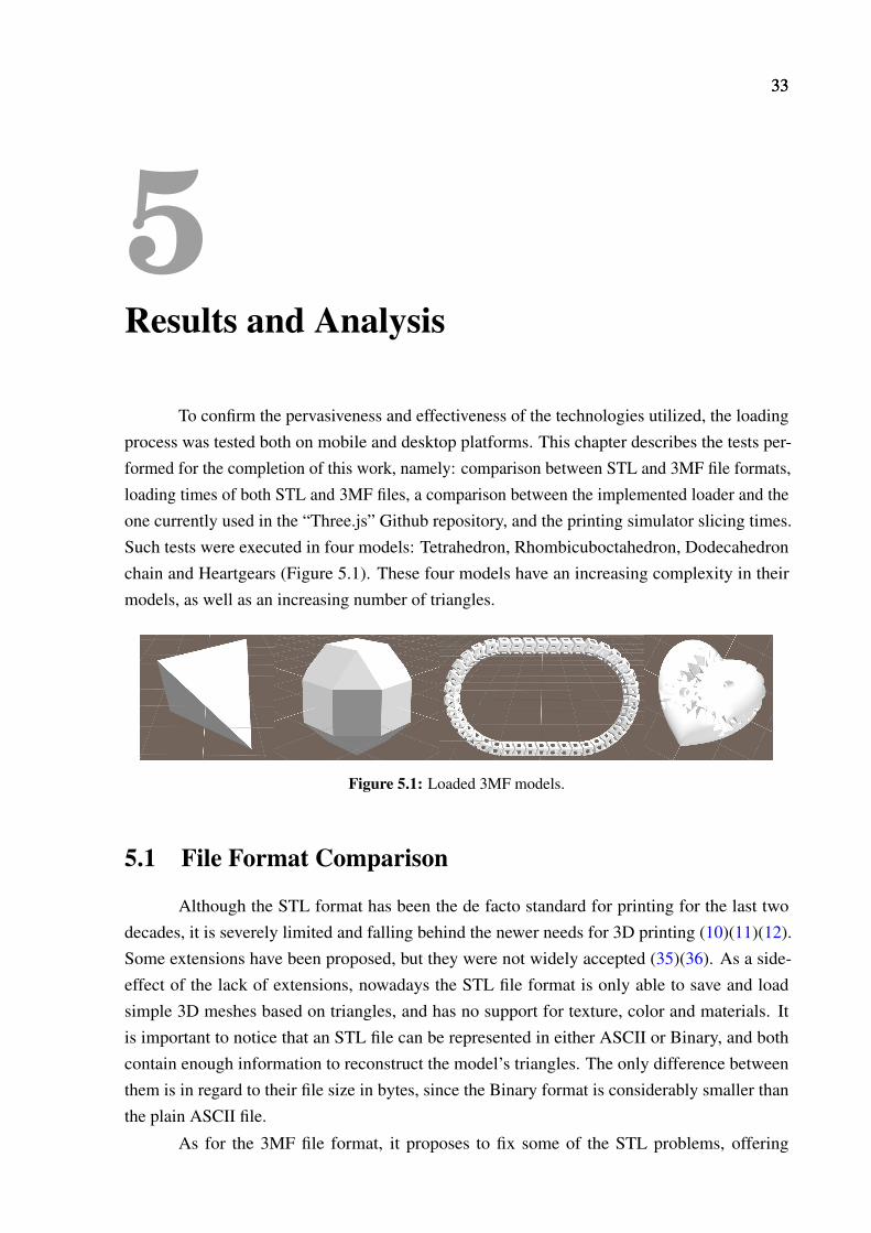
To confirm the pervasiveness and effectiveness of the technologies utilized, the loadingprocess was tested both on mobile and desktop platforms. This chapter describes the tests per-formed for the completion of this work, namely: comparison between STL and 3MF file formats,loading times of both STL and 3MF files, a comparison between the implemented loader and theone currently used in the “Three.js” Github repository, and the printing simulator slicing times.Such tests were executed in four models: Tetrahedron, Rhombicuboctahedron, Dodecahedronchain and Heartgears (Figure 5.1). These four models have an increasing complexity in theirmodels, as well as an increasing number of triangles.
Figure 5.1: Loaded 3MF models.
5.1 File Format Comparison
Although the STL format has been the de facto standard for printing for the last twodecades, it is severely limited and falling behind the newer needs for 3D printing (10)(11)(12).Some extensions have been proposed, but they were not widely accepted (35)(36). As a side-effect of the lack of extensions, nowadays the STL file format is only able to save and loadsimple 3D meshes based on triangles, and has no support for texture, color and materials. Itis important to notice that an STL file can be represented in either ASCII or Binary, and bothcontain enough information to reconstruct the model’s triangles. The only difference betweenthem is in regard to their file size in bytes, since the Binary format is considerably smaller thanthe plain ASCII file.
As for the 3MF file format, it proposes to fix some of the STL problems, offering
34 CHAPTER 5. RESULTS AND ANALYSIS
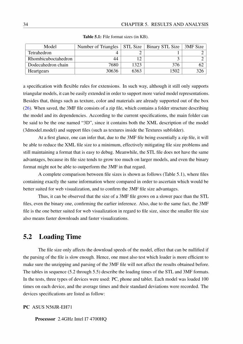
Table 5.1: File format sizes (in KB).
Model Number of Triangles STL Size Binary STL Size 3MF SizeTetrahedron 4 2 1 2Rhombicuboctahedron 44 12 3 2Dodecahedron chain 7680 1323 376 62Heartgears 30636 6363 1502 326
a specification with flexible rules for extensions. In such way, although it still only supportstriangular models, it can be easily extended in order to support more varied model representations.Besides that, things such as texture, color and materials are already supported out of the box(26). When saved, the 3MF file consists of a zip file, which contains a folder structure describingthe model and its dependencies. According to the current specifications, the main folder canbe said to be the one named “3D”, since it contains both the XML description of the model(3dmodel.model) and support files (such as textures inside the Textures subfolder).
At a first glance, one can infer that, due to the 3MF file being essentially a zip file, it willbe able to reduce the XML file size to a minimum, effectively mitigating file size problems andstill maintaining a format that is easy to debug. Meanwhile, the STL file does not have the sameadvantages, because its file size tends to grow too much on larger models, and even the binaryformat might not be able to outperform the 3MF in that regard.
A complete comparison between file sizes is shown as follows (Table 5.1), where filescontaining exactly the same information where compared in order to ascertain which would bebetter suited for web visualization, and to confirm the 3MF file size advantages.
Thus, it can be observed that the size of a 3MF file grows on a slower pace than the STLfiles, even the binary one, confirming the earlier inference. Also, due to the same fact, the 3MFfile is the one better suited for web visualization in regard to file size, since the smaller file sizealso means faster downloads and faster visualizations.
5.2 Loading Time
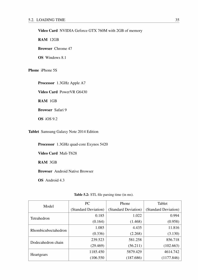
The file size only affects the download speeds of the model, effect that can be nullified ifthe parsing of the file is slow enough. Hence, one must also test which loader is more efficient tomake sure the unzipping and parsing of the 3MF file will not affect the results obtained before.The tables in sequence (5.2 through 5.5) describe the loading times of the STL and 3MF formats.In the tests, three types of devices were used: PC, phone and tablet. Each model was loaded 100times on each device, and the average times and their standard deviations were recorded. Thedevices specifications are listed as follow:
PC ASUS N56JR-EH71
Processor 2.4GHz Intel I7 4700HQ
5.2. LOADING TIME 35
Video Card NVIDIA Geforce GTX 760M with 2GB of memory
RAM 12GB
Browser Chrome 47
OS Windows 8.1
Phone iPhone 5S
Processor 1.3GHz Apple A7
Video Card PowerVR G6430
RAM 1GB
Browser Safari 9
OS iOS 9.2
Tablet Samsung Galaxy Note 2014 Edition
Processor 1.3GHz quad-core Exynos 5420
Video Card Mali-T628
RAM 3GB
Browser Android Native Browser
OS Android 4.3
Table 5.2: STL file parsing time (in ms).
ModelPC
(Standard Deviation)Phone
(Standard Deviation)Tablet
(Standard Deviation)
Tetrahedron0.185
(0.164)1.022
(1.468)0.994
(0.958)
Rhombicuboctahedron1.085
(0.336)4.435
(2.268)11.816(3.130)
Dodecahedron chain239.523(29.469)
581.258(56.211)
856.718(102.663)
Heartgears1185.450(106.550
5879.429(187.686)
4614.742(1177.846)
36 CHAPTER 5. RESULTS AND ANALYSIS
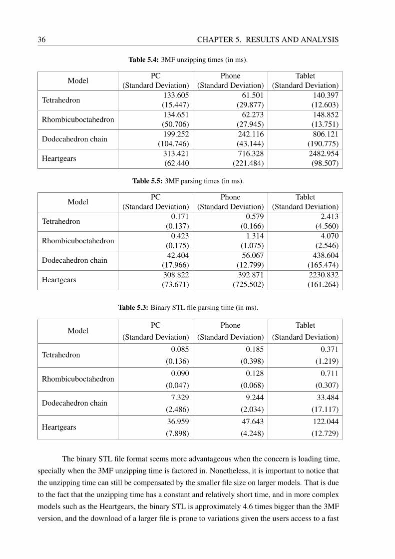
Table 5.4: 3MF unzipping times (in ms).
ModelPC
(Standard Deviation)Phone
(Standard Deviation)Tablet
(Standard Deviation)
Tetrahedron133.605(15.447)
61.501(29.877)
140.397(12.603)
Rhombicuboctahedron134.651(50.706)
62.273(27.945)
148.852(13.751)
Dodecahedron chain199.252
(104.746)242.116(43.144)
806.121(190.775)
Heartgears313.421(62.440
716.328(221.484)
2482.954(98.507)
Table 5.5: 3MF parsing times (in ms).
ModelPC
(Standard Deviation)Phone
(Standard Deviation)Tablet
(Standard Deviation)
Tetrahedron0.171
(0.137)0.579
(0.166)2.413
(4.560)
Rhombicuboctahedron0.423
(0.175)1.314
(1.075)4.070
(2.546)
Dodecahedron chain42.404
(17.966)56.067
(12.799)438.604
(165.474)
Heartgears308.822(73.671)
392.871(725.502)
2230.832(161.264)
Table 5.3: Binary STL file parsing time (in ms).
ModelPC
(Standard Deviation)Phone
(Standard Deviation)Tablet
(Standard Deviation)
Tetrahedron0.085
(0.136)0.185
(0.398)0.371
(1.219)
Rhombicuboctahedron0.090
(0.047)0.128
(0.068)0.711
(0.307)
Dodecahedron chain7.329
(2.486)9.244
(2.034)33.484
(17.117)
Heartgears36.959(7.898)
47.643(4.248)
122.044(12.729)
The binary STL file format seems more advantageous when the concern is loading time,specially when the 3MF unzipping time is factored in. Nonetheless, it is important to notice thatthe unzipping time can still be compensated by the smaller file size on larger models. That is dueto the fact that the unzipping time has a constant and relatively short time, and in more complexmodels such as the Heartgears, the binary STL is approximately 4.6 times bigger than the 3MFversion, and the download of a larger file is prone to variations given the users access to a fast
5.3. LOADERS COMPARISON 37
Internet connection.
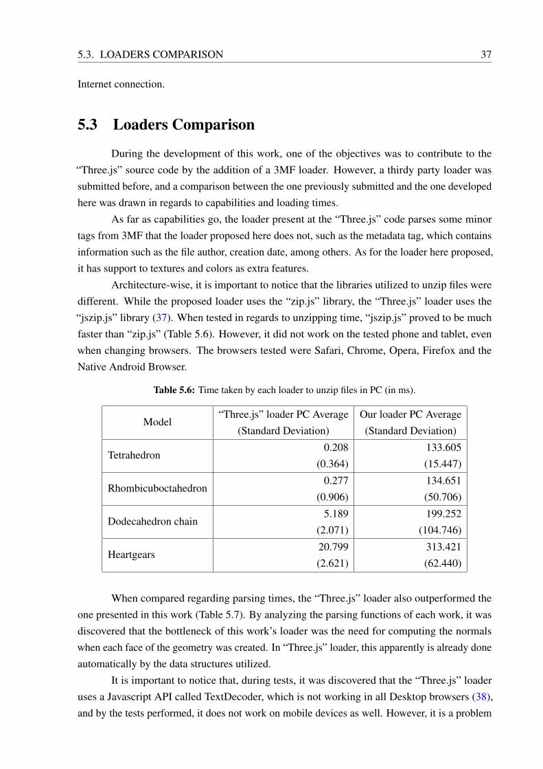
5.3 Loaders Comparison
During the development of this work, one of the objectives was to contribute to the“Three.js” source code by the addition of a 3MF loader. However, a thirdy party loader wassubmitted before, and a comparison between the one previously submitted and the one developedhere was drawn in regards to capabilities and loading times.
As far as capabilities go, the loader present at the “Three.js” code parses some minortags from 3MF that the loader proposed here does not, such as the metadata tag, which containsinformation such as the file author, creation date, among others. As for the loader here proposed,it has support to textures and colors as extra features.
Architecture-wise, it is important to notice that the libraries utilized to unzip files weredifferent. While the proposed loader uses the “zip.js” library, the “Three.js” loader uses the“jszip.js” library (37). When tested in regards to unzipping time, “jszip.js” proved to be muchfaster than “zip.js” (Table 5.6). However, it did not work on the tested phone and tablet, evenwhen changing browsers. The browsers tested were Safari, Chrome, Opera, Firefox and theNative Android Browser.
Table 5.6: Time taken by each loader to unzip files in PC (in ms).
Model“Three.js” loader PC Average
(Standard Deviation)Our loader PC Average(Standard Deviation)
Tetrahedron0.208
(0.364)133.605(15.447)
Rhombicuboctahedron0.277
(0.906)134.651(50.706)
Dodecahedron chain5.189
(2.071)199.252
(104.746)
Heartgears20.799(2.621)
313.421(62.440)
When compared regarding parsing times, the “Three.js” loader also outperformed theone presented in this work (Table 5.7). By analyzing the parsing functions of each work, it wasdiscovered that the bottleneck of this work’s loader was the need for computing the normalswhen each face of the geometry was created. In “Three.js” loader, this apparently is already doneautomatically by the data structures utilized.
It is important to notice that, during tests, it was discovered that the “Three.js” loaderuses a Javascript API called TextDecoder, which is not working in all Desktop browsers (38),and by the tests performed, it does not work on mobile devices as well. However, it is a problem
38 CHAPTER 5. RESULTS AND ANALYSIS
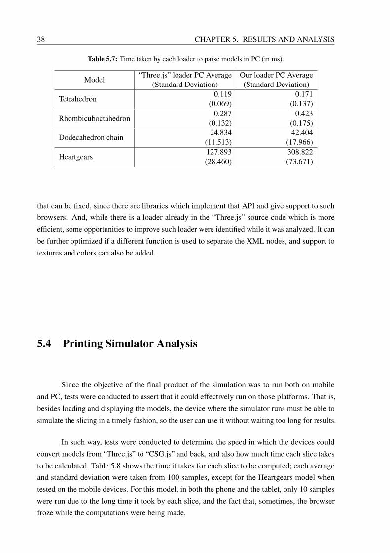
Table 5.7: Time taken by each loader to parse models in PC (in ms).
Model“Three.js” loader PC Average
(Standard Deviation)Our loader PC Average(Standard Deviation)
Tetrahedron0.119
(0.069)0.171
(0.137)
Rhombicuboctahedron0.287
(0.132)0.423
(0.175)
Dodecahedron chain24.834
(11.513)42.404
(17.966)
Heartgears127.893(28.460)
308.822(73.671)
that can be fixed, since there are libraries which implement that API and give support to suchbrowsers. And, while there is a loader already in the “Three.js” source code which is moreefficient, some opportunities to improve such loader were identified while it was analyzed. It canbe further optimized if a different function is used to separate the XML nodes, and support totextures and colors can also be added.
5.4 Printing Simulator Analysis
Since the objective of the final product of the simulation was to run both on mobileand PC, tests were conducted to assert that it could effectively run on those platforms. That is,besides loading and displaying the models, the device where the simulator runs must be able tosimulate the slicing in a timely fashion, so the user can use it without waiting too long for results.
In such way, tests were conducted to determine the speed in which the devices couldconvert models from “Three.js” to “CSG.js” and back, and also how much time each slice takesto be calculated. Table 5.8 shows the time it takes for each slice to be computed; each averageand standard deviation were taken from 100 samples, except for the Heartgears model whentested on the mobile devices. For this model, in both the phone and the tablet, only 10 sampleswere run due to the long time it took by each slice, and the fact that, sometimes, the browserfroze while the computations were being made.

5.4. PRINTING SIMULATOR ANALYSIS 39
Table 5.8: Slicing times (in ms).
ModelPC
(Standard Deviation)Phone
(Standard Deviation)Tablet
(Standard Deviation)
Tetrahedron1.248
(0.878)3.115
(3.337)7.220
(6.766)
Rhombicuboctahedron1.836
(0.914)6.745
(5.894)11.899(5.584)
Dodecahedron chain637.616
(129.334)1002.773(234.394)
3360.233(872.014)
Heartgears2677.336(546.256)
8075.494(2468.433)
19855.443(2078.619)
Given that the more complex models take too long for the slices to be computed, astrategy was devised to minimize such effects. Each slice is only computed once when theapplication is used, and a cache is established, so if the user so desires, the simulation can beviewed smoothly after its first execution.
Nevertheless, the caching strategy did not solve one problem: complex models cannot beeasily simulated through the use of the CSG intersection operation, specially on mobile deviceswhich sometimes froze when the simulation was running. So, that leaves two options for thesimulations to be effective on mobile devices: either optimize the used functions, or pre-computethe simulation and leave it available as a source file that the final user will use without noticing.
From these two options, the latter is considered to be a better option for incrementingthis work on the future, given that it would also make the voxelization of the models possibleregardless of the time that would take for the simulation to run, and the results would be availablein a fast manner both on PC and mobile.

414141
6Conclusion
The proposed loader was successfully developed, and it was validated through theimplemented printing simulator. Meanwhile, the tests conducted were important for properlycomparing the STL format and the new 3MF format, not only for their capabilities, but alsoregarding their possible use in a web application.
When considering file sizes and capabilities, the 3MF is a clear winner, for it having abetter scalability, extensibility, and support for textures and colors. For instance, the Heartgearsbinary STL model is 4.6 times bigger than its 3MF counterpart, and it only contains a triangulatedmodel.
Nonetheless, one can argue that, due to greater loading times, the binary STL file ispreferable when considering mobile devices, since in a worst case it can take approximately 38.6times more to load a complex 3MF model than it takes to load the same model in binary STL (asthe Heartgears model in the tablet). However, the analysis made when comparing our Loaderversus the “Three.js” loader showed some points where our Loader can be deeply optimized, andas such the loading times for the 3MF format can be greatly reduced, effectively nullifying thisargument in the future.
As for the mobile uses for the simulator, it is clear that more optimized approaches willbe needed in the future, since the gap between mobile and desktop is still enough to make someapplications instances, as in the simulator when working with large models, impractical. Thetests showed that a model can take up to almost 20 seconds for just one slice to be produced inmobile, and in some cases the tab simply crashed without the simulation running.
Regarding the open source contributions of this work, the fact that a more efficient loaderalready exists at the “Three.js” source code does not mean that there will not be any contribution.Support to texture and color can be added to it, since it is something that was developed in thiswork, and opportunities for improving it were also identified while its code was being analyzed.Therefore, given that the capabilities of the loader developed in this work include color andtexture loading, and the one currently at the “Three.js” code base does not, a contribution to theopen source community is possible.
Also, as a result of this work, a paper has been accepted for publication at the HCI

42 CHAPTER 6. CONCLUSION
International 2016. (39)
6.1 Future Work
As an upgrade for the visualizer as a whole, there is the need for UX testing in order forits user to receive the better simulation experience that is possible. It is noteworthy that, involvedin this simulation improvement, measures should be taken to optimize the software.
Also, texture is not currently being processed as part of the slicing process, and addingsuch mapping on top of the current printing simulator would improve the experience as a whole,as it enables more complex objects to be loaded into the simulator.
The loader can also be configured to take into consideration tags that were not processedin this work due to time restrictions, such as tags that concern metadata and which objects willbe actually built by the printer.
434343
References
[1] “ WebGL: OpenGL ES 2.0 for the Web - Khronos Group.” https://www.khronos.org/webgl/. Accessed: 2015-09-16.
[2] “Three.js, A Javascript 3D library.” http://threejs.org/. Accessed: 2015-09-16.
[3] “Babylon.js.” http://www.babylonjs.com/. Accessed: 2016-01-14.
[4] N. Rego and D. Koes, “3dmol. js: molecular visualization with webgl,” Bioinformatics,vol. 31, no. 8, pp. 1322–1324, 2015.
[5] B. Sawicki and B. Chaber, “Efficient visualization of 3d models by web browser,” Comput-
ing, vol. 95, no. 1, pp. 661–673, 2013.
[6] “What is 3D printing?.” http://3dprinting.com/what-is-3d-printing/.Accessed: 2015-09-16.
[7] “3D Printing Has Expanded Faster Than Expected.” http://bit.ly/1LmQUI2. Ac-cessed: 2015-09-16.
[8] P. Dudek, “Fdm 3d printing technology in manufacturing composite elements,” Archives of
Metallurgy and Materials, vol. 58, no. 4, pp. 1415–1418, 2013.
[9] A. Bandyopadhyay, S. Bose, and S. Das, “3d printing of biomaterials,” MRS Bulletin,vol. 40, no. 02, pp. 108–115, 2015.
[10] K. K. Jurrens, “Standards for the rapid prototyping industry,” Rapid Prototyping Journal,vol. 5, no. 4, pp. 169–178, 1999.
[11] V. Kumar and D. Dutta, “An assessment of data formats for layered manufacturing,” Ad-
vances in Engineering Software, vol. 28, no. 3, pp. 151–164, 1997.
[12] R. Hague and P. Reeves, Rapid prototyping, tooling and manufacturing, vol. 117. iSmithersRapra Publishing, 2000.
[13] J. D. Hiller and H. Lipson, “Stl 2.0: a proposal for a universal multi-material additivemanufacturing file format,” in Proceedings of the Solid Freeform Fabrication Symposium,no. 1, pp. 266–278, Citeseer, 2009.
[14] “What is 3MF?.” http://3mf.io/what-is-3mf/. Accessed: 2015-09-16.
[15] “OpenGL.” https://www.opengl.org/. Accessed: 2016-01-07.
[16] K. Gray, Microsoft DirectX 9 programmable graphics pipeline. Microsoft Press, 2003.
44 REFERENCES
[17] “Neymar Jr Crazy Skills.” https://hbr.org/2015/07/
3d-printing-is-changing-the-way-we-think. Accessed: 2016-01-07.
[18] C. H. Ahrens and N. Volpato, Prototipagem rápida: tecnologias e aplicações. EdgardBlücher, 2007.
[19] R. A. Buswell, R. Soar, A. G. Gibb, and A. Thorpe, “Freeform construction: mega-scalerapid manufacturing for construction,” Automation in Construction, vol. 16, no. 2, pp. 224–231, 2007.
[20] A. GORNI, “Prototipagem rápida: O que é, quem faz e por que utilizá-la,” Plástico
Industrial, vol. 1, pp. 230–239, 2001.
[21] “3D Hubs: Local 3D printing services and 3D Printers.” https://www.3dhubs.com/.Accessed: 2016-01-07.
[22] “3D print your own jewelry? This startup says yes.” http://fortune.com/2015/10/16/trove-3d-printed-jewelry/. Accessed: 2016-01-07.
[23] “Normal.” https://www.nrml.com/. Accessed: 2016-01-07.
[24] “Here’s Why 2016 Could Be 3D Printing’s Breakout Year.” http://fortune.com/2015/12/30/2016-consumer-3d-printing/. Accessed: 2016-01-07.
[25] “3D Printing Is Changing the Way We Think.” https://hbr.org/2015/07/
3d-printing-is-changing-the-way-we-think. Accessed: 2016-01-07.
[26] “3MF Specification.” http://3mf.io/what-is-3mf/3mf-specification/.Accessed: 2015-09-16.
[27] T. Ecma, “Office open xml,” 2006.
[28] A. A. Requicha and H. B. Voelcker, “Constructive solid geometry,” 1977.
[29] “Constructive solid geometry,” in Introduction to Geometric Computing, pp. 277–283,Springer London, 2008.
[30] D. H. Laidlaw, W. B. Trumbore, and J. F. Hughes, “Constructive solid geometry forpolyhedral objects,” in Computer Graphics (Proceedings of SIGGRAPH 86), vol. 20,pp. 161–170, Aug. 1986.
[31] “zip.js A JavaScript library to zip and unzip files.” https://gildas-lormeau.
github.io/zip.js/. Accessed: 2016-01-15.
[32] “CSG.js.” https://github.com/evanw/csg.js/. Accessed: 2015-09-16.
[33] “OpenJSCad.” http://openjscad.org/. Accessed: 2015-09-16.

REFERENCES 45
[34] “Constructive Solid Geometry with CSG.js.” http://learningthreejs.com/
blog/2011/12/10/constructive-solid-geometry-with-csg-js/. Ac-cessed: 2015-09-16.
[35] W. Chiu and S. Tan, “Multiple material objects: from cad representation to data format forrapid prototyping,” Computer-Aided Design, vol. 32, no. 12, pp. 707–717, 2000.
[36] I. Stroud and P. Xirouchakis, “Stl and extensions,” Advances in Engineering Software,vol. 31, no. 2, pp. 83–95, 2000.
[37] “JSzip.” https://github.com/Stuk/jszip. Accessed: 2016-01-07.
[38] “TextDecoder.” https://developer.mozilla.org/en-US/docs/Web/API/TextDecoder/decode. Accessed: 2016-01-14.
[39] J. V. d. F. Leite, J. M. X. N. Teixeira, and V. Teichreib, “Optimizing 3d object visualizationon the web.” Manuscript accepted for publication in HCI International, 2016.


Appendix

494949
A3MF Specification
This appendix contains a subset of the tags contained in the specification of the 3MFXML file. Such subset consists of the tags that were most relevant to this work. For the fullspecification, please refer to the 3MF specification [11].
model The root of 3Dmodel.model file, it contains all of the XML information, and there mustbe exactly one model node inside the XML file. As children, it has the metadata, resourcesand build tags, and also has the following attributes:
unit Specifies the unit used to interpret all vertices, locations, or measurements in themodel. It can have one of the following values: micron, millimeter, centimeter, inch,foot and meter.
requiredextensions Which 3MF extensions are required to process the XML file.
xml:lang Specifies which language must be used for the current and any descendantelements.
resources Acts as the root element for 3D objects definition. As children, it has the followingtags: basematerials, colorgroup, textue2dgroup, compositematerials, multiproperties andobject.
object Describes reusable 3D objects that may be used or composed into more complex objects.It has the mesh and components tags as children, and the following attributes:
id Unique value, enabling this tag to be referenced by other children of the resource tagor item tags.
type The function of this object in the model. Possible values are: model, support orother.
pid Reference to the property group element (a colorgroup, for instance) with the matchingid attribute value.
pindex References a zero-based index inside the properties group specified by pid. Thisproperty is used to build the object.

50 APPENDIX A. 3MF SPECIFICATION
thumbnail Path to a 3D texture of type JPEG or PNG that represents a rendered image ofthe object.
partnumber A partnumber, which editors should maintain during the process of modify-ing and deriving objects.
name Name of the object.
mesh Is the root of a triangular mesh representation of an object. It contains as children thevertices and triangles tags.
vertices Represents a set of vertices and must contain less than 231 vertex tags inside it.
vertex Represents a point in 3D space. It can be referenced by a triangle tag through an implicit0-based index given by its positioning. It has the following attributes:
x The x coordinate of the vertex.
y The y coordinate of the vertex.
z The z coordinate of the vertex.
triangles Represents a set of triangles and must contain less than 231 triangle tags inside it.
triangle Describes reusable 3D objects that may be used or composed into more complexobjects. It has the mesh and components tags as children, and the following attributes:
v1 A zero-based index referencing the first vertex of the triangles.
v2 A zero-based index referencing the second vertex of the triangles.
v3 A zero-based index referencing the third vertex of the triangles.
p1 Overrides the object-level pindex for the first vertex of the triangle.
p2 Overrides the object-level pindex for the second vertex of the triangle.
p3 Overrides the object-level pindex for the third vertex of the triangle.
pid Overrides the object-level pid for the triangle.
colorgroup Represents a set of colors and must contain less than 231 color tags inside it. It hasthe following attribute:
id Unique value, enabling this tag to be referenced by objects or triangles.
color Represents a color, and can be referenced by a triangle through an implicit 0-based indexgiven by its positioning. It has the following attribute:
color A sRGB color in hexadecimal format.

51
texture2dgroup Represents a set of texture coordinates and must contain less than 231 tex2coordtags inside it. It has the following attributes:
id Unique value, enabling this tag to be referenced by objects or triangles.
texid References a texture2d tag.
tex2coord Represents coordinates which enable mapping from a texture to a vertex, and can bereferenced by a triangle through an implicit 0-based index given by its positioning. It hasthe following attributes:
u U-coordinate within the texture.
v V-coordinate within the texture.
texture2d Represents the texture image data. It has the following attributes:
id Unique value, enabling this tag to be referenced by texture2dgroups tag.
path The path to the image containing texture data.
contenttype The content type of the texture data. Valid values are image/jpeg and im-
age/png.
box Bounding box defining the boundaries of the texture swatch in UV coordinates. Ithas the form “U V width height”.
tylestyleu Specifies how tiling should occur in the U axis in order to fill the requestedarea.
tylestylev Specifies how tiling should occur in the V axis in order to fill the requestedarea.