Embed Size (px)
Citation preview
THE UNIVERSITY OF QUEENSLAND
AUSTRALIA
Enhancing Awareness to Support Teleoperation of a Bulldozer
John James Dudley
B. E. (Mechanical) (Hons), B. A.
A thesis submitted for the degree of Master of Philosophy at
The University of Queensland in 2014
School of Mechanical & Mining Engineering
Abstract
Bulldozers are frequently used to execute work in hazardous environments. Teleoperationprovides a viable method for allowing operators to perform work without being directlyexposed to the hazards of these environments. However, removing the operator fromthe bulldozer presents many challenges associated with reduced task engagement andcontrollability. The relocation of the operator and placement within a remote teleoperationsystem may be simplistically modelled as placing a filter on the operator’s inputs andoutputs. The various cues that would excite the sensory systems of an operator on boardthe bulldozer must be remotely replicated. However, the fidelity and timeliness of cuesprovided to the teleoperator are unavoidably constrained by limitations in the systems thateffect this replication. Likewise, there are similar implications for accurately achieving amachine response in accord with the command outputs of the operator.
This thesis focuses principally on the inputs to the teleoperator with the aim of identifyinghow perception enhancements might be applied to alter the characteristics of this inputfilter. The motivation for this research is to determine what factors are critical to achievinghigh levels of teleoperation performance and user acceptance.
To conduct this investigation, an enhanced perception cell capable of high fidelity repli-cation of motion, visual and aural cues is integrated with an existing bulldozer teleoper-ation system. The cell enables targeted analysis of the influence of individual feedbackcues on performance and user acceptance. Experiments have been conducted with theenhanced perception cell for a structured bulldozing task. Results indicate that visualquality is a dominant factor influencing operator performance. Motion feedback providesno additional benefit beyond that provided by enhanced visual quality. The value of taskvisualisation to support accuracy and planning is also highlighted.
i

Declaration by author
This thesis is composed of my original work, and contains no material previously pub-lished or written by another person except where due reference has been made in thetext. I have clearly stated the contribution by others to jointly-authored works that I haveincluded in my thesis.
I have clearly stated the contribution of others to my thesis as a whole, including statisti-cal assistance, survey design, data analysis, significant technical procedures, professionaleditorial advice, and any other original research work used or reported in my thesis. Thecontent of my thesis is the result of work I have carried out since the commencement ofmy research higher degree candidature and does not include a substantial part of workthat has been submitted to qualify for the award of any other degree or diploma in anyuniversity or other tertiary institution. I have clearly stated which parts of my thesis, ifany, have been submitted to qualify for another award.
I acknowledge that an electronic copy of my thesis must be lodged with the UniversityLibrary and, subject to the General Award Rules of The University of Queensland, im-mediately made available for research and study in accordance with the Copyright Act
1968.
I acknowledge that copyright of all material contained in my thesis resides with the copy-right holder(s) of that material. Where appropriate I have obtained copyright permissionfrom the copyright holder to reproduce material in this thesis.
ii

Publications during candidature
John Dudley, Jonathan Aw, and Ross McAree. Minimal perception requirements to sup-port effective remote control of bulldozers. Technical Report C20021, ACARP, 2013.
Publications included in this thesis
John Dudley, Jonathan Aw, and Ross McAree. Minimal perception requirements to sup-port effective remote control of bulldozers. Technical Report C20021, ACARP, 2013.
This report was prepared as an outcome of the wider research project from which thisthesis stems. There are portions of text, considered directly relevant and authored bymyself, and results from this report which are included in this thesis.
Contributor Statement of contributionJohn Dudley (Candidate) Authorship and editing (70%)Jonathan Aw Authorship and editing (15%)Ross McAree Authorship and editing (15%)
iii
Contributions by others to the thesis
The main study, of which the research presented in this thesis represents a component,was undertaken as part of a project funded by the Australian Coal Association ResearchProgram (ACARP). This research project, entitled ‘Perception Requirements for EffectiveTeleoperation of Dozers’, was executed by the Smart Machines Group at the Universityof Queensland through the Cooperative Research Centre for Mining (CRCMining) withextensive support from Caterpillar Inc.
The design and construction of the experimental apparatus used within this study wasa collaborative effort of the Smart Machine Group project team. The execution of theexperiments as well as the continued development and maintenance of the experimentalapparatus was also a collaborative exercise.
Statement of parts of the thesis submitted to qualify for the award of another degree
None.
iv

Acknowledgements
This thesis has evolved from a collaborative research project executed by CRCMiningand Caterpillar with funding from the Australian Coal Association Research Program(ACARP). I would like to acknowledge the contribution made by these groups in provid-ing the funding and in kind support that allowed this project to be conducted and gave methe opportunity to write this thesis.
I owe much credit to the many people involved in the project. I would to thank those atCaterpillar for their kind and patient assistance. I feel the bulldozer operators who actedas subjects in this study deserve special recognition for their resilience and helpfulnessdespite the often frustrating experimental regime to which they were subjected.
I would like to thank my colleagues at CRCMining who were instrumental in originatingthe project and seeing it achieve its outcomes: Dr Anthony Reid who fathered the projectand gave it direction; Dr Zane Smith who developed the software and sacrificed his life totesting; Jonathan Aw who developed the audio-visual system and endured my characterflaws with his classic composure; as well as Lachlan Palmer and a number of others whoat various times gave assistance. Lastly, I would like to thank my supervisor, ProfessorRoss McAree, who challenged, educated, prodded and reformed me while also giving methe time and freedom to explore my interests.
v

Keywords
teleoperation, bulldozer, perception, motion feedback, visual feedback
Australian and New Zealand Standard Research Classifications (ANZSRC)
ANZSRC code: 091302, Automation and Control Engineering, 100%
Fields of Research (FoR) Classification
FoR code: 0913, Mechanical Engineering, 100%
vi
Table of Contents
1 Teleoperation, remote perception and operator performance 11.1 Teleoperation . . . . . . . . . . . . . . . . . . . . . . . . . . . . . . . . 11.2 The teleoperated bulldozer . . . . . . . . . . . . . . . . . . . . . . . . . 31.3 Does perception influence performance? . . . . . . . . . . . . . . . . . . 41.4 Perception for teleoperation . . . . . . . . . . . . . . . . . . . . . . . . . 5
1.4.1 Visual feedback . . . . . . . . . . . . . . . . . . . . . . . . . . . 51.4.2 Audio feedback . . . . . . . . . . . . . . . . . . . . . . . . . . . 81.4.3 Cue substitution . . . . . . . . . . . . . . . . . . . . . . . . . . 91.4.4 Latency . . . . . . . . . . . . . . . . . . . . . . . . . . . . . . . 111.4.5 Motion feedback . . . . . . . . . . . . . . . . . . . . . . . . . . 121.4.6 Assessing perception requirements . . . . . . . . . . . . . . . . . 17
1.5 Thesis overview . . . . . . . . . . . . . . . . . . . . . . . . . . . . . . . 19
2 Examining perception requirements for teleoperation 212.1 Aim . . . . . . . . . . . . . . . . . . . . . . . . . . . . . . . . . . . . . 212.2 Methodology . . . . . . . . . . . . . . . . . . . . . . . . . . . . . . . . 222.3 Perception cues relevant to bulldozer operation . . . . . . . . . . . . . . 242.4 Feedback factors for experimental evaluation . . . . . . . . . . . . . . . 26
2.4.1 Vision . . . . . . . . . . . . . . . . . . . . . . . . . . . . . . . . 262.4.2 Motion . . . . . . . . . . . . . . . . . . . . . . . . . . . . . . . 272.4.3 Audio . . . . . . . . . . . . . . . . . . . . . . . . . . . . . . . . 282.4.4 Contextual awareness . . . . . . . . . . . . . . . . . . . . . . . . 292.4.5 Summary of feedback factors to be evaluated . . . . . . . . . . . 29
3 Experimental evaluation of perception requirements 313.1 Aim . . . . . . . . . . . . . . . . . . . . . . . . . . . . . . . . . . . . . 313.2 The conventional teleoperation system . . . . . . . . . . . . . . . . . . . 313.3 The enhanced perception cell . . . . . . . . . . . . . . . . . . . . . . . . 32
vii
3.3.1 Audio-visual feedback system . . . . . . . . . . . . . . . . . . . 33
3.3.2 Motion feedback system . . . . . . . . . . . . . . . . . . . . . . 35
3.3.3 Task visualisation . . . . . . . . . . . . . . . . . . . . . . . . . . 36
3.4 Experimental procedure . . . . . . . . . . . . . . . . . . . . . . . . . . . 37
3.4.1 Design factors . . . . . . . . . . . . . . . . . . . . . . . . . . . 38
3.4.2 Structured task . . . . . . . . . . . . . . . . . . . . . . . . . . . 38
3.4.3 Nuisance factors . . . . . . . . . . . . . . . . . . . . . . . . . . 39
3.4.4 Experimental Controls . . . . . . . . . . . . . . . . . . . . . . . 40
3.4.5 Performance metrics . . . . . . . . . . . . . . . . . . . . . . . . 40
3.4.6 Experimental plan . . . . . . . . . . . . . . . . . . . . . . . . . 43
3.5 Results . . . . . . . . . . . . . . . . . . . . . . . . . . . . . . . . . . . . 44
3.5.1 Operator performance is degraded under teleoperation . . . . . . 45
3.5.2 Introducing motion feedback does not substantially influence taskcompletion time . . . . . . . . . . . . . . . . . . . . . . . . . . 46
3.5.3 Depth of view dominates visual quality and audio . . . . . . . . . 54
3.5.4 Task visualisation is critical to task completion . . . . . . . . . . 69
3.6 Discussion of key results . . . . . . . . . . . . . . . . . . . . . . . . . . 71
4 Task analysis for bulldozer operation 754.1 Aim . . . . . . . . . . . . . . . . . . . . . . . . . . . . . . . . . . . . . 75
4.2 Linking perception to task behaviour . . . . . . . . . . . . . . . . . . . . 75
4.3 Modelling the human . . . . . . . . . . . . . . . . . . . . . . . . . . . . 76
4.4 Analysis of bulldozer operation and teleoperation . . . . . . . . . . . . . 77
4.4.1 Task and cue surveys . . . . . . . . . . . . . . . . . . . . . . . . 77
4.4.2 Operator feedback . . . . . . . . . . . . . . . . . . . . . . . . . 84
4.5 Modelling bulldozer control behaviour . . . . . . . . . . . . . . . . . . . 86
4.6 Mapping perception to control . . . . . . . . . . . . . . . . . . . . . . . 90
4.7 Overview of assembled model . . . . . . . . . . . . . . . . . . . . . . . 94
5 Consolidating perception requirements 955.1 Aim . . . . . . . . . . . . . . . . . . . . . . . . . . . . . . . . . . . . . 95
5.2 Perception groupings . . . . . . . . . . . . . . . . . . . . . . . . . . . . 95
5.2.1 Vision . . . . . . . . . . . . . . . . . . . . . . . . . . . . . . . . 95
5.2.2 Audio . . . . . . . . . . . . . . . . . . . . . . . . . . . . . . . . 97
5.2.3 Motion . . . . . . . . . . . . . . . . . . . . . . . . . . . . . . . 97
5.2.4 Task visualisation . . . . . . . . . . . . . . . . . . . . . . . . . . 99
viii
5.3 Ranking perception requirements . . . . . . . . . . . . . . . . . . . . . . 100
6 Conclusions and recommendations for further investigation 1036.1 Conclusion . . . . . . . . . . . . . . . . . . . . . . . . . . . . . . . . . 1036.2 Original contributions of the thesis . . . . . . . . . . . . . . . . . . . . . 1056.3 Recommendations for future work . . . . . . . . . . . . . . . . . . . . . 1056.4 Concluding remarks . . . . . . . . . . . . . . . . . . . . . . . . . . . . . 106
Bibliography 107
A Experimental Record 113
ix
List of Figures
1.1 Afferent and efferent filters in teleoperation. . . . . . . . . . . . . . . . . 2
1.2 Elements of a bulldozer. . . . . . . . . . . . . . . . . . . . . . . . . . . 3
1.3 Degrees of freedom of a bulldozer blade. . . . . . . . . . . . . . . . . . . 4
1.4 Teleoperation of TALON robot using 3D interface. . . . . . . . . . . . . 7
1.5 Max Planck Institute motion simulator. . . . . . . . . . . . . . . . . . . . 15
2.1 View from inside bulldozer cab. . . . . . . . . . . . . . . . . . . . . . . 25
2.2 Areas of significantly restricted visibility on a Caterpillar D8T. . . . . . . 25
3.1 Conventional teleoperation system. . . . . . . . . . . . . . . . . . . . . . 32
3.2 Cropped segment of output feed at remote station illustrating differencein video quality. . . . . . . . . . . . . . . . . . . . . . . . . . . . . . . . 33
3.3 Typical 3D frame prior to display interlacing. . . . . . . . . . . . . . . . 34
3.4 Anaglyph representation of the 3D view. . . . . . . . . . . . . . . . . . . 34
3.5 Bulldozer frame and Platform frame. . . . . . . . . . . . . . . . . . . . . 35
3.6 Task visualisation display. . . . . . . . . . . . . . . . . . . . . . . . . . 37
3.7 Structured test task. . . . . . . . . . . . . . . . . . . . . . . . . . . . . . 38
3.8 On board versus non-line-of-sight teleoperation. . . . . . . . . . . . . . . 46
3.9 Completion under different motion feedback configurations . . . . . . . . 47
3.10 Motion cues - mean volume removed from within slot over time. . . . . . 49
3.11 Motion cues - mean time taken to remove volume segment. . . . . . . . . 51
3.12 Motion cues - mean volume per push. . . . . . . . . . . . . . . . . . . . 52
3.13 Operator A - mean workload total score. . . . . . . . . . . . . . . . . . . 53
3.14 Operator A - mean workload element scores. . . . . . . . . . . . . . . . 54
3.15 Completion under different visual and audio quality configurations. . . . 55
3.16 Completion with audio, visual and motion enhancements. . . . . . . . . . 57
3.17 Combined vision, audio and motion cues - mean volume removed fromwithin slot over time. . . . . . . . . . . . . . . . . . . . . . . . . . . . . 59
x
3.18 Combined vision, audio and motion cues - mean time taken to removevolume segment. . . . . . . . . . . . . . . . . . . . . . . . . . . . . . . 61
3.19 Combined vision, audio and motion cues - mean volume per push. . . . . 623.20 Left joystick control inputs over test duration. . . . . . . . . . . . . . . . 633.21 Right joystick control inputs over test duration. . . . . . . . . . . . . . . 643.22 x-position of bulldozer within the slot over time. . . . . . . . . . . . . . . 653.23 Mean number of joystick corrections per minute. . . . . . . . . . . . . . 663.24 Mean joystick inputs per minute on each control axis. . . . . . . . . . . . 663.25 Operator B - mean workload total score. . . . . . . . . . . . . . . . . . . 673.26 Operator B - mean workload element scores. . . . . . . . . . . . . . . . . 683.27 Without task visualiser - percentage complete at termination of test. . . . 693.28 Without task visualiser - mean volume removed from within slot over time. 703.29 Without task visualiser - mean workload total score. . . . . . . . . . . . . 723.30 Without task visualiser - mean workload element scores. . . . . . . . . . 72
4.1 Situation awareness model. . . . . . . . . . . . . . . . . . . . . . . . . . 784.2 State transition model. . . . . . . . . . . . . . . . . . . . . . . . . . . . 874.3 Hierarchical Task Analysis for slot bulldozing. . . . . . . . . . . . . . . . 884.4 Model of bulldozer operation. . . . . . . . . . . . . . . . . . . . . . . . 91
xi

List of Tables
3.1 Audio-visual feedback system cues. . . . . . . . . . . . . . . . . . . . . 353.2 Isolated motion cues. . . . . . . . . . . . . . . . . . . . . . . . . . . . . 363.3 Augmentations that can be applied to the existing remote station. . . . . . 383.4 Nuisance factors. . . . . . . . . . . . . . . . . . . . . . . . . . . . . . . 393.5 NASA TLX rating scale definitions. . . . . . . . . . . . . . . . . . . . . 423.6 Data collection stage 1 - summary of test configurations. . . . . . . . . . 443.7 Data collection stage 2 - summary of test configurations. . . . . . . . . . 453.8 On board versus non-line-of-sight teleoperation descriptive statistics. . . . 463.9 Motion configurations. . . . . . . . . . . . . . . . . . . . . . . . . . . . 473.10 Descriptive statistics for motion feedback configurations. . . . . . . . . . 483.11 Motion factors and levels. . . . . . . . . . . . . . . . . . . . . . . . . . . 483.12 Operator A - total workload score. . . . . . . . . . . . . . . . . . . . . . 533.13 Audio-visual configurations. . . . . . . . . . . . . . . . . . . . . . . . . 553.14 Descriptive statistics for visual and audio quality test configurations. . . . 563.15 Vision factors and levels. . . . . . . . . . . . . . . . . . . . . . . . . . . 563.16 Audio factors and levels. . . . . . . . . . . . . . . . . . . . . . . . . . . 563.17 Combined vision and motion configurations. . . . . . . . . . . . . . . . . 573.18 Descriptive statistics for configurations with audio visual and motion en-
hancements. . . . . . . . . . . . . . . . . . . . . . . . . . . . . . . . . . 583.19 Vision and motion factors and levels. . . . . . . . . . . . . . . . . . . . . 583.20 Joystick correction count for typical test. . . . . . . . . . . . . . . . . . . 653.21 Operator B - total workload score. . . . . . . . . . . . . . . . . . . . . . 673.22 Without task visualiser - total workload score. . . . . . . . . . . . . . . . 71
4.1 Motion focus - task focus statements. . . . . . . . . . . . . . . . . . . . . 794.2 Motion focus - cue focus statements. . . . . . . . . . . . . . . . . . . . . 794.3 Motion focus - task focus statement responses. . . . . . . . . . . . . . . . 804.4 Motion focus - cue focus statement responses. . . . . . . . . . . . . . . . 81
xii
4.5 Vision, audio and motion focus - task focus statements. . . . . . . . . . . 824.6 Vision, audio and motion focus - cue focus statements. . . . . . . . . . . 824.7 Vision, audio and motion focus - task focus statement responses. . . . . . 834.8 Vision, audio and motion focus - cue focus statement responses. . . . . . 83
A.1 Completion time results - stage 1 . . . . . . . . . . . . . . . . . . . . . . 114A.2 Completion time results - stage 1 continued . . . . . . . . . . . . . . . . 115A.3 Completion time results - stage 2 . . . . . . . . . . . . . . . . . . . . . . 116A.4 Completion time results - stage 2 continued . . . . . . . . . . . . . . . . 117
xiii
List of Abbreviations
NMF Remote station with no motion feedback
CMF Remote station with combined motion feedback
PMF Remote station with pitch motion cues only
VMF Remote station with vibration cues only
TMF Remote station with translational acceleration cues only
NMF-TV Remote station with no motion feedback and no visualiser
CMF-TV Remote station with combined motion and no visualiser
2DSR Remote station in standard audio-visual configuration
2DHR Remote station with high resolution 2D video and stereo audio
3DHR Remote station with high resolution 3D video and stereo audio
2DHR-A Remote station with high resolution 2D video and no stereo audio
3DHR+PMF Remote station with high resolution 3D video, stereo audio andpitch motion cues
3DHR+FMF Remote station with high resolution 3D video, stereo audio andfull motion feedback
OB On board operation
xiv
CHAPTER 1
Teleoperation, remote perception and operatorperformance
1.1 Teleoperation
As humans we are capable of acting as expert control systems. This capability is due inpart to the robust feedback channels we are able to establish through our sensory pro-cesses. Our senses are involved in everything we do and we attach great value to the rolethey play in supporting interaction with our surroundings.
Teleoperation is the operation of machines at a distance by remote control (Oxford En-glish Dictionary, 2013). An effective teleoperator1 must feed the senses of the humancontroller; it must extend human sensing to the remote environment so that the operatorreceives sufficient information, presented in a suitable format for remote machine oper-ation to be effective. It must also translate the operator commands so that they result inintended actions by the machine at the remote environment.
This thesis is concerned with the teleoperation of bulldozers in mining operations, themotivation for which is the desire to reduce the fatal risks that operators can be exposedto when on-board these machines. Teleoperation in this application fundamentally altersthe conventional relationship between the operator and the machine. The teleoperator isinterposed between the operator and machine: cues relevant to machine operation mustbe remotely replicated to the operator and must initiate appropriate operator commands
1Any remote-controlled machine which mimics or responds to the actions of a human controller at adistance (Oxford English Dictionary, 2013)
1
1.1 Teleoperation
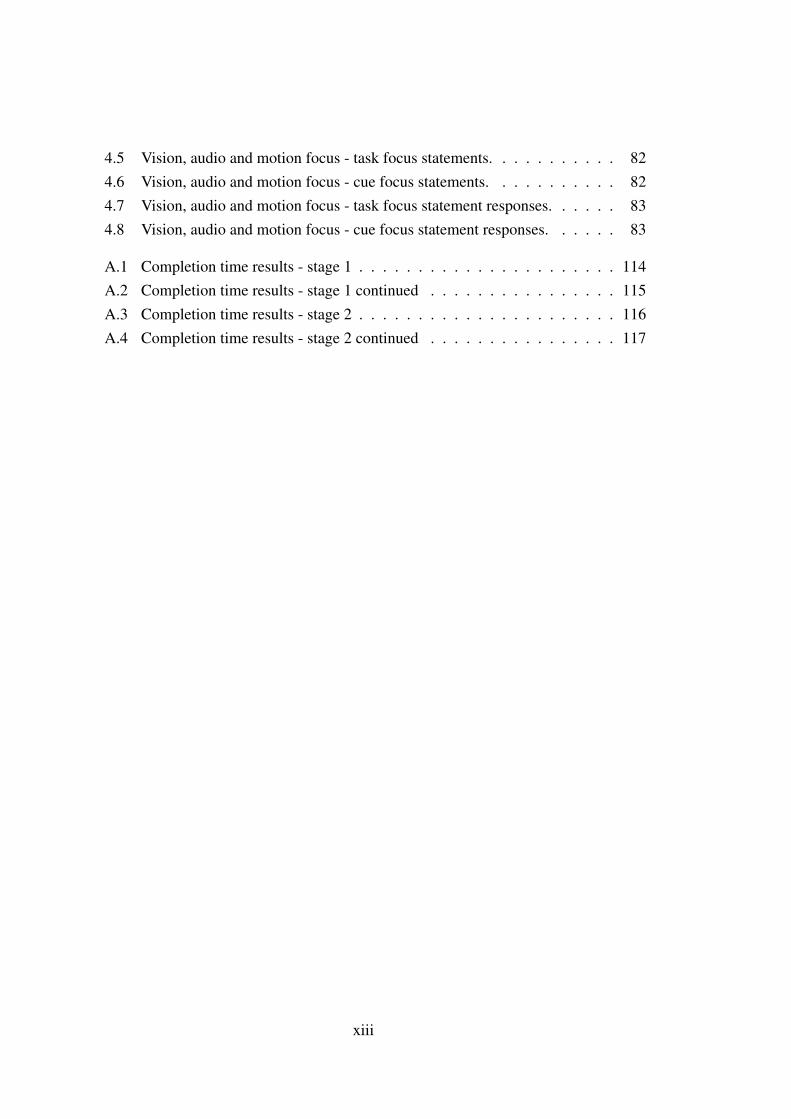
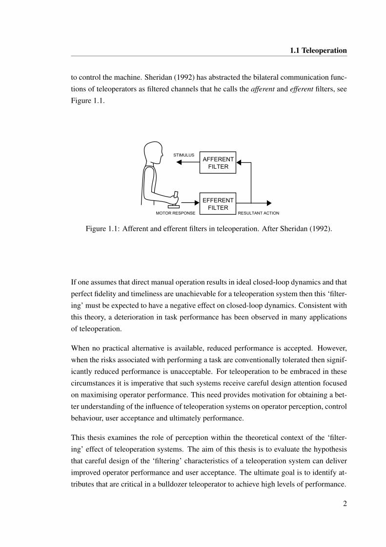
to control the machine. Sheridan (1992) has abstracted the bilateral communication func-tions of teleoperators as filtered channels that he calls the afferent and efferent filters, seeFigure 1.1.
AFFERENTFILTER
EFFERENTFILTER
STIMULUS
MOTOR RESPONSE RESULTANT ACTION
Figure 1.1: Afferent and efferent filters in teleoperation. After Sheridan (1992).
If one assumes that direct manual operation results in ideal closed-loop dynamics and thatperfect fidelity and timeliness are unachievable for a teleoperation system then this ‘filter-ing’ must be expected to have a negative effect on closed-loop dynamics. Consistent withthis theory, a deterioration in task performance has been observed in many applicationsof teleoperation.
When no practical alternative is available, reduced performance is accepted. However,when the risks associated with performing a task are conventionally tolerated then signif-icantly reduced performance is unacceptable. For teleoperation to be embraced in thesecircumstances it is imperative that such systems receive careful design attention focusedon maximising operator performance. This need provides motivation for obtaining a bet-ter understanding of the influence of teleoperation systems on operator perception, controlbehaviour, user acceptance and ultimately performance.
This thesis examines the role of perception within the theoretical context of the ‘filter-ing’ effect of teleoperation systems. The aim of this thesis is to evaluate the hypothesisthat careful design of the ‘filtering’ characteristics of a teleoperation system can deliverimproved operator performance and user acceptance. The ultimate goal is to identify at-tributes that are critical in a bulldozer teleoperator to achieve high levels of performance.
2
1.2 The teleoperated bulldozer
1.2 The teleoperated bulldozer
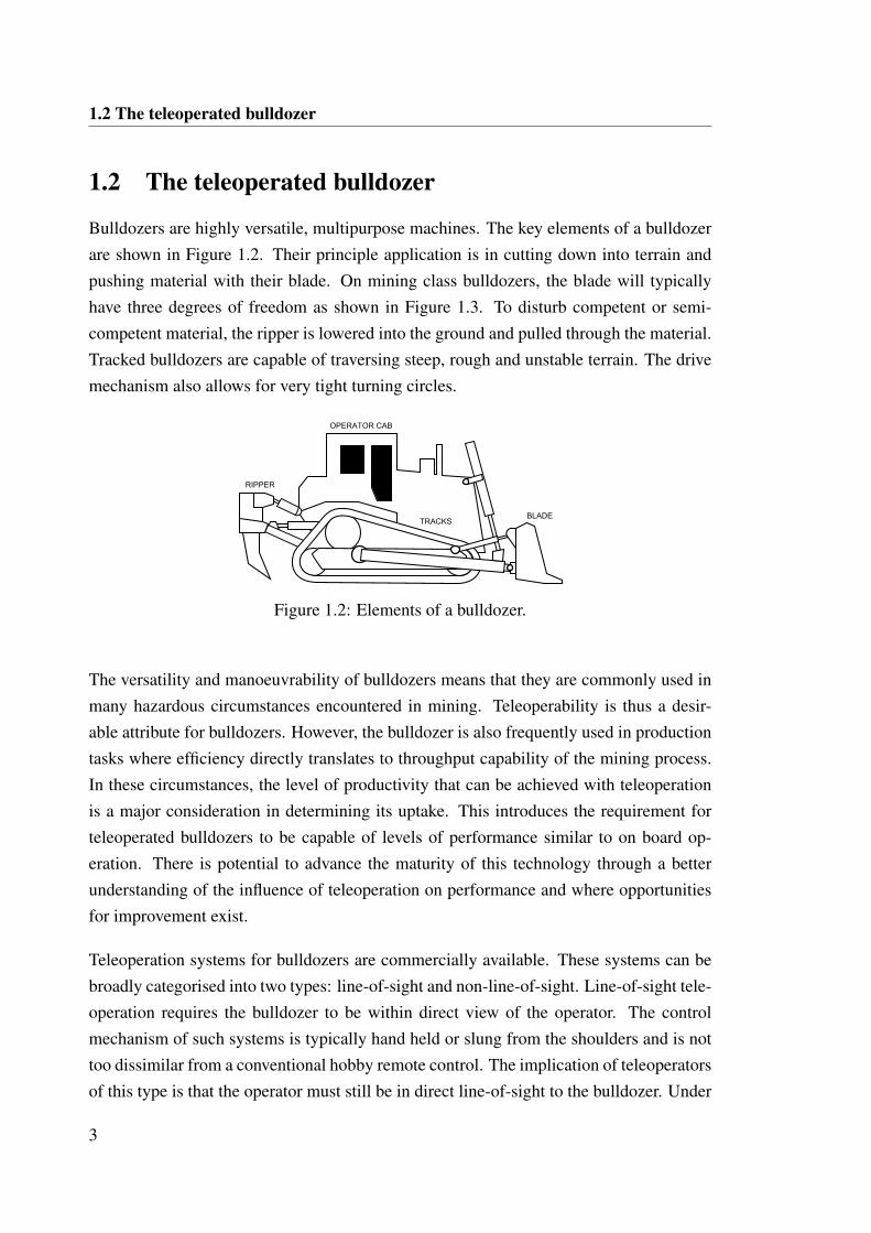
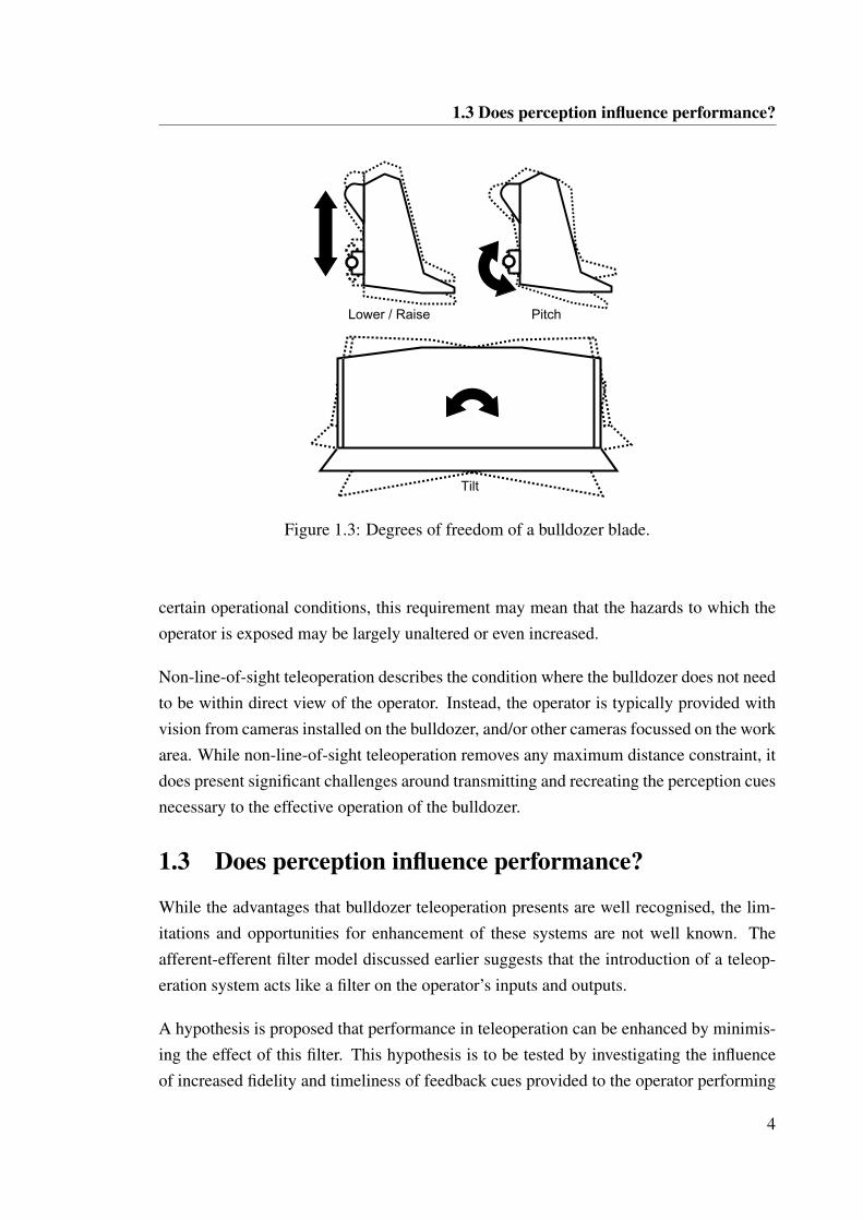
Bulldozers are highly versatile, multipurpose machines. The key elements of a bulldozerare shown in Figure 1.2. Their principle application is in cutting down into terrain andpushing material with their blade. On mining class bulldozers, the blade will typicallyhave three degrees of freedom as shown in Figure 1.3. To disturb competent or semi-competent material, the ripper is lowered into the ground and pulled through the material.Tracked bulldozers are capable of traversing steep, rough and unstable terrain. The drivemechanism also allows for very tight turning circles.
BLADE
RIPPER
OPERATOR CAB
TRACKS
Figure 1.2: Elements of a bulldozer.
The versatility and manoeuvrability of bulldozers means that they are commonly used inmany hazardous circumstances encountered in mining. Teleoperability is thus a desir-able attribute for bulldozers. However, the bulldozer is also frequently used in productiontasks where efficiency directly translates to throughput capability of the mining process.In these circumstances, the level of productivity that can be achieved with teleoperationis a major consideration in determining its uptake. This introduces the requirement forteleoperated bulldozers to be capable of levels of performance similar to on board op-eration. There is potential to advance the maturity of this technology through a betterunderstanding of the influence of teleoperation on performance and where opportunitiesfor improvement exist.
Teleoperation systems for bulldozers are commercially available. These systems can bebroadly categorised into two types: line-of-sight and non-line-of-sight. Line-of-sight tele-operation requires the bulldozer to be within direct view of the operator. The controlmechanism of such systems is typically hand held or slung from the shoulders and is nottoo dissimilar from a conventional hobby remote control. The implication of teleoperatorsof this type is that the operator must still be in direct line-of-sight to the bulldozer. Under
3
1.3 Does perception influence performance?
Lower / Raise Pitch
Tilt
Figure 1.3: Degrees of freedom of a bulldozer blade.
certain operational conditions, this requirement may mean that the hazards to which theoperator is exposed may be largely unaltered or even increased.
Non-line-of-sight teleoperation describes the condition where the bulldozer does not needto be within direct view of the operator. Instead, the operator is typically provided withvision from cameras installed on the bulldozer, and/or other cameras focussed on the workarea. While non-line-of-sight teleoperation removes any maximum distance constraint, itdoes present significant challenges around transmitting and recreating the perception cuesnecessary to the effective operation of the bulldozer.
1.3 Does perception influence performance?
While the advantages that bulldozer teleoperation presents are well recognised, the lim-itations and opportunities for enhancement of these systems are not well known. Theafferent-efferent filter model discussed earlier suggests that the introduction of a teleop-eration system acts like a filter on the operator’s inputs and outputs.
A hypothesis is proposed that performance in teleoperation can be enhanced by minimis-ing the effect of this filter. This hypothesis is to be tested by investigating the influenceof increased fidelity and timeliness of feedback cues provided to the operator performing
4
1.4 Perception for teleoperation
non-line-of-sight teleoperation. The research question this thesis seeks to answer is: what
feedback attributes are critical to maximising bulldozer teleoperation performance and
user acceptance?
1.4 Perception for teleoperation
Humans perceive their environment through interpreting sensory cues. This perceptionis critical to performing physical tasks. The relative significance of different sensorysystems in perceiving an environment and performing a task varies depending on thenature of the environment and the nature of the task.
The operation of a vehicle is a relatively complex exercise where multiple sensory sys-tems are called upon. The visual, aural, vestibular, tactile and proprioceptive systemsall contribute to the operator’s perception and ability to maintain control. The informa-tion provided by these sensory systems is fused by neural pathways before being furtherprocessed within different loops to derive an appropriate control response. The need tocapture the information that would normally be obtained directly by the sensory systemsand instead replicate it elsewhere so that it might be similarly interpreted is a significanttechnical challenge for teleoperation systems.
Teleoperation is not new and extensive research has been conducted into identifying fac-tors that influence performance. Numerous studies have examined the role played by thedifferent sensory systems and how feedback might best be provided.
Prominent avenues of exploration have been in visual feedback, audio feedback, cue sub-stitution and the impact of latency. Motion feedback has emerged more recently as arelevant cue for teleoperation in performing certain activities.
1.4.1 Visual feedback
The human visual system is specialised for the perception of spatial structure. The abilityto perceive and interpret space is critical in many teleoperation applications. Unfortu-nately, the capture and transmission of visual feedback for use in teleoperation can bedata intensive. In addition, the natural capabilities of humans in an environment, i.e.binocular vision, field of view, and the ability to move the head to obtain different views,can be very difficult to accurately replicate remotely.
5
1.4 Perception for teleoperation
The challenge of providing appropriate visual information in teleoperation has motivatednumerous studies. Chen et al. (2007) conducted an extensive review of the literatureon vision-related human performance issues around teleoperation. The common vision-related issues encountered are lack of depth perception, poor situation awareness andcognitive tunnelling due to restricted field of view. The consolidation of the findings fromthe reviewed literature leads to the authors recommending wide field of view, stereoscopicdisplays and predictive displays in presence of high latency.
Murphy (1995) examined the potential for using a panospheric camera that is capable ofcapturing a full 360 degree field of view. Aside from the benefit of not requiring multipleor actuated cameras to capture appropriate field of view, the display produced by thepanospheric camera was suspected of supporting a more immersive experience due to itsseamless representation. Halme et al. (1999) identified that head tracking for adaptivevisual display showed benefits when an unfamiliar or changeable task was encountered.However, there was no obvious benefit when a familiar task was being performed.
Depth information, as provided by stereoscopic video images, has been found to enhancecertain aspects of performance but with its benefit highly dependent on the nature of thetask. Drascic et al. (1989) examined the impact of 2D versus 3D visual feedback intelemanipulation of a bomb disposal robot application. The results of the study indicatedthat stereoscopic vision reduced completion time initially but with sufficient practice,similar completion times were achieved in the 2D visual configuration. This suggests that3D depth cues are more intuitive, but similar information can be gained from the 2D videowith sufficient practice.
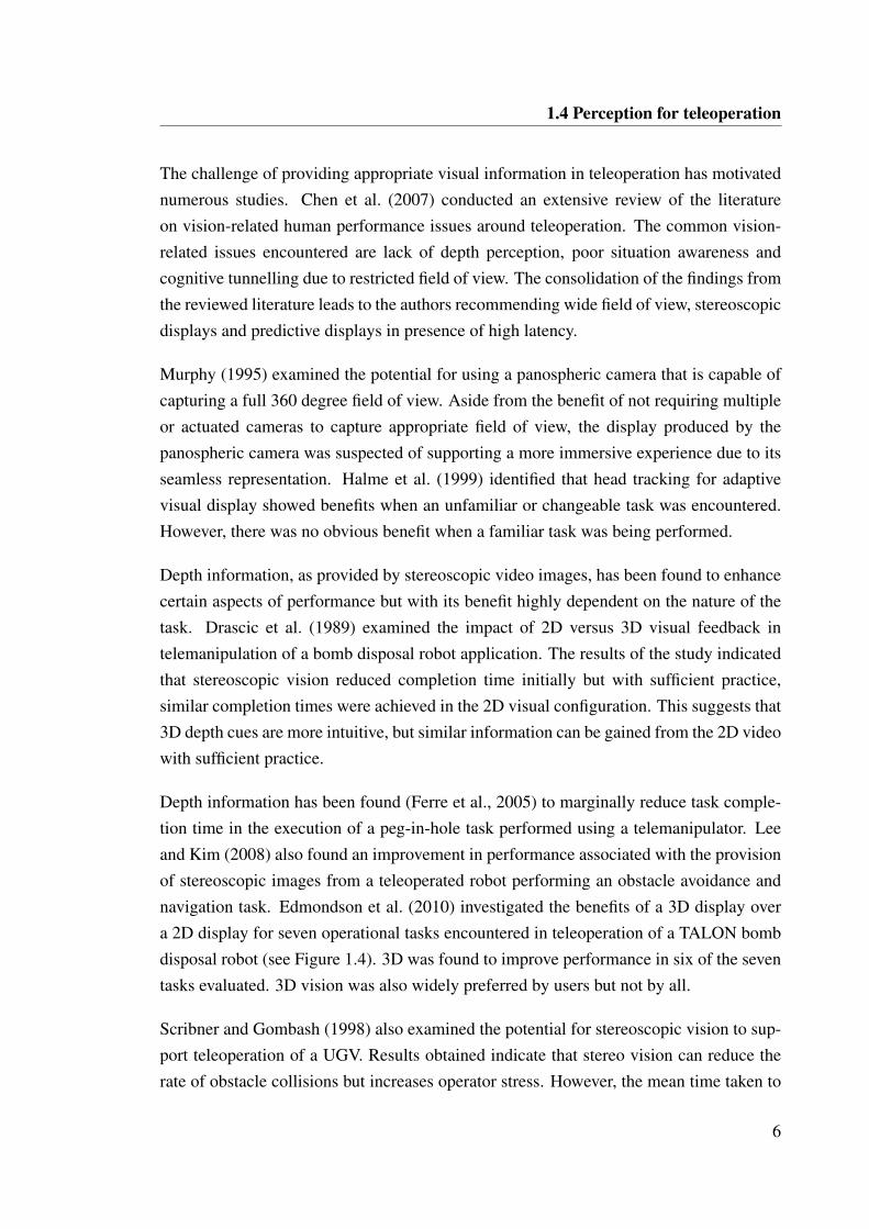
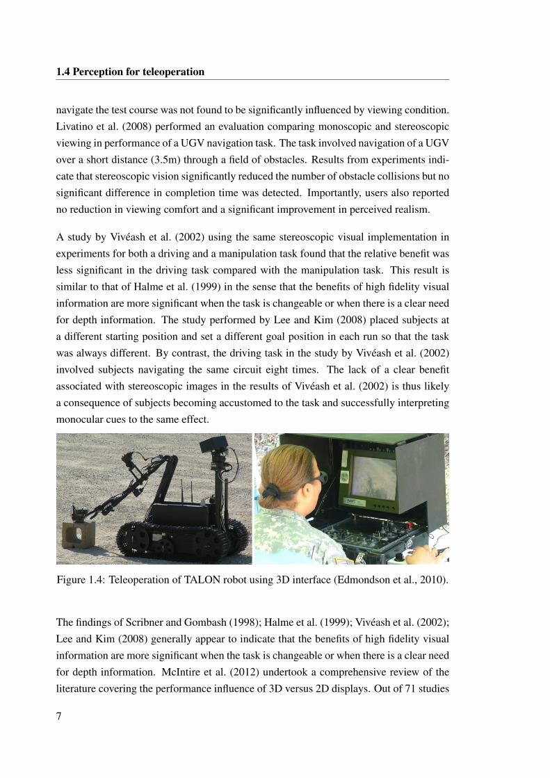
Depth information has been found (Ferre et al., 2005) to marginally reduce task comple-tion time in the execution of a peg-in-hole task performed using a telemanipulator. Leeand Kim (2008) also found an improvement in performance associated with the provisionof stereoscopic images from a teleoperated robot performing an obstacle avoidance andnavigation task. Edmondson et al. (2010) investigated the benefits of a 3D display overa 2D display for seven operational tasks encountered in teleoperation of a TALON bombdisposal robot (see Figure 1.4). 3D was found to improve performance in six of the seventasks evaluated. 3D vision was also widely preferred by users but not by all.
Scribner and Gombash (1998) also examined the potential for stereoscopic vision to sup-port teleoperation of a UGV. Results obtained indicate that stereo vision can reduce therate of obstacle collisions but increases operator stress. However, the mean time taken to
6
1.4 Perception for teleoperation
navigate the test course was not found to be significantly influenced by viewing condition.Livatino et al. (2008) performed an evaluation comparing monoscopic and stereoscopicviewing in performance of a UGV navigation task. The task involved navigation of a UGVover a short distance (3.5m) through a field of obstacles. Results from experiments indi-cate that stereoscopic vision significantly reduced the number of obstacle collisions but nosignificant difference in completion time was detected. Importantly, users also reportedno reduction in viewing comfort and a significant improvement in perceived realism.
A study by Viveash et al. (2002) using the same stereoscopic visual implementation inexperiments for both a driving and a manipulation task found that the relative benefit wasless significant in the driving task compared with the manipulation task. This result issimilar to that of Halme et al. (1999) in the sense that the benefits of high fidelity visualinformation are more significant when the task is changeable or when there is a clear needfor depth information. The study performed by Lee and Kim (2008) placed subjects ata different starting position and set a different goal position in each run so that the taskwas always different. By contrast, the driving task in the study by Viveash et al. (2002)involved subjects navigating the same circuit eight times. The lack of a clear benefitassociated with stereoscopic images in the results of Viveash et al. (2002) is thus likelya consequence of subjects becoming accustomed to the task and successfully interpretingmonocular cues to the same effect.
Figure 1.4: Teleoperation of TALON robot using 3D interface (Edmondson et al., 2010).
The findings of Scribner and Gombash (1998); Halme et al. (1999); Viveash et al. (2002);Lee and Kim (2008) generally appear to indicate that the benefits of high fidelity visualinformation are more significant when the task is changeable or when there is a clear needfor depth information. McIntire et al. (2012) undertook a comprehensive review of theliterature covering the performance influence of 3D versus 2D displays. Out of 71 studies
7
1.4 Perception for teleoperation
reviewed, 41 (58%) showed 3D to be better than 2D based on the performance metricselected in each study. When the studies were categorised into task types, the highest ra-tios of results showing positive impact of 3D was seen in spatial manipulation and spatialunderstanding tasks. However, McIntire et al. (2012) make an important consolidatingobservation that ‘3D helps little or sometimes not at all for tasks that are simple or well-learned, or for tasks that do not rely heavily on depth information for good performance.’What the research into stereoscopic vision for task performance does show is that there arepotential benefits that can be derived and their are implementations that are accepted byusers. However, there appear to be many factors that dictate whether or not stereoscopicvision will be beneficial for a given teleoperation task.
1.4.2 Audio feedback
Audio can provide a powerful cue to support teleoperation through a variety of mech-anisms. One key mechanism is the perception of spatial information by means of theaudible signal emitted from an object. For example, the loudness of an audio signal cangive an indication of the distance to the emitting object while direction can be inferredfrom differences in the audio signal perceived by the two ears. Another mechanism isthe perception of information about an object’s state and behaviour based on the emittedacoustic response. Audio feedback also has strong potential for providing informationthat is readily interpreted without distraction through mechanisms such as voiced warn-ings and alarms. Furthermore, studies of the human sensory system indicate that humanreactions to acoustic stimulus are faster than reactions to visual stimulus (Welch and War-ren, 1986).
Nagai et al. (2002) investigated the potential benefit of audio feedback in assisting tele-operation of a manipulating arm in space. The audio feedback provided to operatorsconsisted of three components. The first audio component generated a motor sound thatwas proportional to the magnitude of the force and torque imparted on the end-effector.The second audio component involved voiced announcement of key state changes. Thethird audio component voiced the command data issued as auditory confirmation. In lim-ited experimental trials, a reduction in task completion time of between 30 and 50% wasobserved. The audio feedback also reduced the amount of time spent focused on the sta-tus display. An additional finding of the study was that distinctly different results wereobserved when tests where conducted in a virtual simulation of the task compared to ac-tual teleoperation of the real satellite arm. This was suspected to be a consequence of
8
1.4 Perception for teleoperation
the added urgency and stress associated with the real task and the correspondingly realconsequences of poor performance.
Liu and Meng (2005) examined the impact of audio feedback in supporting teleoperationof a mobile robot in an obstacle navigation and target finding task. The researches exam-ined four conditions: vision only, audio only, vision and audio in consistent directions,and vision and audio in random directions. Due to observed learning effects in the ex-periments, the completion time results are not readily interpretable. Some useful generalobservations were made, however, including that the visual and audio feedback corrobo-rate each other but when conflicting audio information is present, vision will dominate.This study was re-executed by Liu and Wang (2012) with a more precise audio feed-back implementation. The results indicated no significant difference in completion timebetween vision-only and audio-only configurations suggesting that audio may be com-pletely substituted for vision in a simple task with relevant audio cues.
Complicating any assessment of the influence of individual feedback cues, is the fact thataudio feedback has been found to have an interaction effect on visual perception. Thisis most observable in the case of resolving ambiguous visual cues describing motion.Sekuler et al. (1997) conducted an experiment in which an ambiguous motion situationwas presented to subjects. Two identical disks were presented on a digital display andshown to move directly towards each other, coincide, then continue in the same trajec-tory. The presence and timing of audio cues at and around the point of coincidence wasinvestigated for its impact on whether subjects perceived the objects to have bounced offeach other or to have passed through each other. The researchers observed that when anaudible click was presented at the point of coincidence, approximately 60% of the sub-jects indicated that they perceived ‘bouncing’ as compared with only 20% when no clickwas presented. While this finding clearly shows that there are complex human intersen-sory interactions, it does suggest that audio cues may be useful in resolving ambiguousinformation or otherwise corroborating perception cues.
1.4.3 Cue substitution
The difficulty associated with providing useful visual information in certain applicationshas motivated research into cue substitution. The objective in these studies is to deter-mine whether visual information can be substituted with alternate sensory informationthat is intuitive to environment perception. In 1936, de Florez demonstrated that pilotscould successfully maintain control of an aeroplane in flight while blindfolded when two
9
1.4 Perception for teleoperation
instrument values were presented aurally. This indicates that vision can be completelysubstituted by audio in certain control tasks.
Massimino (1992) performed a comprehensive study of the potential for sensory sub-stitution to assist in space teleoperation. Specifically, the focus of Massimino was oninvestigating the potential for auditory and vibrotactile displays to act as substitutes forforce feedback. Experimental results were used to specify three distinct models for theeffect of sensory substitution under different qualities of visual feedback. When visualconditions are ideal, simple sensory substitutions have no effect on performance. Whenvisual conditions are degraded, simple sensory substitutions can improve performance.However, when visual conditions are ideal but sensory substitutions are complex, the re-sult is distraction and degraded performance.
Lathan and Tracey (2002) experimented with a gesture based control glove for teleoperat-ing a small UGV. In addition to conventional video and audio feedback, object proximityinformation was given by vibrotactile inserts in the sleeve of the control glove. The sonararray on the UGV was mapped to particular vibrotactile inserts in the sleeve to providean indication of the direction of an obstacle. The number of task errors was found tobe significantly reduced when the vibrotactile feedback was provided in addition to thevideo feedback. Spatial awareness was evaluated through four separate tests targetingrecognition and manipulation aspects of spatial awareness. The results of Lathan andTracey indicated that higher spatial awareness resulted in faster task completion times.However, this trend was not observed in the condition with the vibrotactile feedback.These findings have also been echoed in experiments conducted by Uusisalo and Huhtala(2009, 2011) in which a small hydraulic excavator was remotely operated by means ofa hand-held gaming controller capable of providing vibrotactile feedback. Testing withinexperienced operators found that task completion time was reduced when using the re-mote control compared with on board operation. However, the impact on task completiontime of adding vibrotactile feedback to the remote control was negligible. Despite thislimited effect on task completion time, the subjects’ sense of perception and feeling ofcontrol (as determined through a survey) was enhanced by the inclusion of the vibro-tactile feedback. In discussion of their experimental results, Lathan and Tracey suggestthat vibrotactile feedback may have been more useful to the operators with low spatialawareness. Lathan and Tracey conclude that an individual’s spatial perception skills maydictate what feedback characteristics they require to effectively perform a given task.
10
1.4 Perception for teleoperation
These studies have shown that information provided through non conventional channelscan provide some compensation for poor or even complete lack of direct visual feed-back. The general philosophy that has evolved around teleoperation encourages the useof multiple channels of sensory information provided they are coordinated and intuitive.This suggests the value of determining what sensory information is essential to effectivelyperforming the task that will be teleoperated and providing cues based on this assessment.
1.4.4 Latency
Examination of factors concerning a teleoperator’s ability to make changes in the environ-ment has revealed that time delay is a key determinant of performance. A number of earlystudies (Sheridan and Ferrell, 1963; Adams, 1962), motivated by the large transmissiondelays expected in earth-space teleoperation, were made to investigate the effect of delayon operator control. Experiments conducted by Sheridan and Ferrell (1963) demonstratedthat when performing a remote manipulation task in the presence of delay, operators willfollow a move-and-wait strategy. If this strategy is used, completion time can be approxi-mately calculated as a function of the number of discontinuous moves required to achievetolerance and the magnitude of the delay.
Adams (1962) conducted a comprehensive set of experiments with a remotely operatedfour wheeled ground vehicle. It was observed that a continuous path could be navigatedwith 98% accuracy at 2.96 km/h but if a three second delay was introduced to the controlloop then a similar level of accuracy could only be achieved after the vehicle speed wasreduced to 0.44 km/h (approximately 15% of the original speed). However, it has alsobeen shown (Cunningham et al., 2001) that for certain tasks under certain circumstance,operators can adapt to delay and achieve comparable peformance to executing the sametask with no delay.
In the consolidated literature review performed by Chen et al. (2007), latency was widelyfound to be detrimental but the latency threshold past which performance is significantlydegraded varies depending on the task performed (from 170 ms up to 500ms). Variationin latency is suggested to be particularly detrimental, and potentially more detrimentalthan larger but fixed latency.
11
1.4 Perception for teleoperation
1.4.5 Motion feedback
The concept of applying vestibular cues to assist teleoperation through direct motion feed-back has received attention only recently. This is largely a result of the traditionally highcost of motion-bases and quality motion sensors. Nevertheless, significant literature existsaround how vestibular cues influence human control behaviour and performance thanksto extensive research aimed at developing accurate pilot models to assist with the designof aircraft dynamics and simulators.
The relevance of vestibular cues to many vehicle operation tasks suggests that motionfeedback can provide a useful channel of sensory information for teleoperation. Earlystudies (Shirley and Young, 1968; Stapleford et al., 1969; Ringland et al., 1971; Ringlandand Stapleford, 1972; Levison, 1976) aimed at using motion feedback in conjunction withsome vision based task to examine operator control behaviour. This early research wasmotivated by a desire to better understand operator control behaviour in order to assistwith the design and testing of aircraft dynamics.
Shirley and Young (1968) examined the influence of roll-motion cues in isolation on acompensatory tracking task with a joystick. Their results indicated that adding motionfeedback to the visual feedback had an effect of generating additional phase lead abovefrequencies of 3 rad/s and increasing gain more broadly. This resulted in a reduction intracking error on the majority of vehicle dynamics evaluated with the effect more pro-nounced for lower-order systems.
Stapleford et al. (1969) made a similar study of the influence of motion feedback on pilotdynamics in a roll control task. The task involved simulated hovering in gusty air with rolland lateral translation motion imparted to the operator. The experimental results indicatedthat visual feedback dominates pilot dynamics at low frequencies while motion feedbackdominates at high frequencies. Consistent with Shirley and Young, it was observed thatmotion feedback increased gain and reduced phase lag. There was a clear distinctionbetween controlled elements requiring low frequency pilot lead compared to those that donot, with the former showing a greater improvement with motion feedback than the later.The authors also considered the design of simulators making the comment that washoutless than 2 rad/s has only a minor effect. Consideration of vestibular sensory thresholdswas also given with pitch and roll rate thresholds of 2.6◦/s and 3.2◦/s respectively anda linear acceleration threshold of 0.01g described. The small magnitude of the linearacceleration threshold places challenging demands on motion washout filter design for
12
1.4 Perception for teleoperation
travel limited simulators as observed in a later study by Ringland and Stapleford (1972).
Ringland et al. (1971) extended this original study by Stapleford et al. (1969) with a sixdegrees-of-freedom simulator performing a similar precision hovering task but with addi-tional motion cues. Trials run with an angular motion only configuration revealed a cleardistinction in performance and general operator preference compared with a combinedlinear and angular motion configuration. Test subjects commented that the linear motionwas at times confusing and distracting. The researchers suggested that the angular motiononly configuration was beneficial because the g-vector could be used more directly as anindicator of attitude. Investigation of operator instrument scanning behaviour revealedthat the introduction of motion reduced dwell time and dwell fraction on the attitude dis-play. In terms of motion fidelity, the authors noted the operators’ comments about effectsof simulator noise, vibration and motion limiting (hitting motion-base range limits) beingparticularly disconcerting. These same comments were reiterated in later experiments ex-ploring a different control task (Ringland and Stapleford, 1972). A brief investigation ofthe operators’ sensitivity to vision-motion disparity revealed that an effective time con-stant of 0.2s or greater was detrimental.
In a study similar to that of Shirley and Young (1968) and Stapleford et al. (1969), Levison(1976) obtained conflicting results on the effect of motion cues. In contrast with theformer studies, Levison found that motion cues generated phase lag at high frequenciesrather than generating phase lead. Also, a greater improvement was demonstrated with theintroduction of motion cues for higher-order systems. The model developed by Levisonalso suggests that if operator attention is distracted by another task then motion cues willhave a greater benefit.
Hosman and van der Vaart (1976) explored thresholds of motion perception again moti-vated by adding fidelity to the pilot model. It was found that distraction increases motionperception thresholds and also that person to person perception thresholds can differ sig-nificantly. However, if the operator has an internal model of how the system they arecontrolling is expected to behave, their motion perception is improved.
To gain a better understanding of how sensory systems interact, a number of studies haveattempted to identify the interplay between the visual and vestibular systems. It has beenshown that visual cues implemented in subtly different ways can have an effect similarto providing motion cues. For example, Hosman and van der Vaart (1981) demonstratedthat performance of a roll disturbance rejection and tracking task can be improved by the
13
1.4 Perception for teleoperation
provision of motion and/or peripheral visual cues. For the results obtained, the improve-ment provided by motion cues compared to central monitor display only was 60% in thedisturbance task and 33% in the following task. Analysis of the closed loop characteris-tics provides results consistent with established theory for the disturbance task (increasedcrossover frequency) but inconsistent results for the following task (decreased crossoverfrequency). Hosman and van der Vaart (1981) describe two alternate theories for the ap-parent positive interaction between vestibular and peripheral visual information: eitherredundant information improves accuracy or differences in sensors and perceptions com-bine to improve accuracy. A more recent study by Hosman and Stassen (1999) identifiedthat motion stimuli are perceived earlier by the vestibular system than they are by thevisual system.
Schroeder (1998) examined the requirements for helicopter flight simulation using a highdisplacement motion platform. The study examined the relative effects of roll, yaw, lat-eral translation and vertical motion. Lateral translation and vertical motion were found tobe the dominant motion cues in improving performance, perceived fidelity and reducingworkload. Yaw and roll were found to be of less importance. An additional test demon-strated that visual yaw cues could provide accurate sensation without actual yaw motion.The identified benefit of vertical platform motion conflicted with early comments fromsubjects who indicated that the vertical axis control task was primarily visual. On thispoint, Schroeder (1998, chap. 9) cautions that care should be taken when interpreting thesubjective impressions of subjects relating to the benefits of particular motion cues.
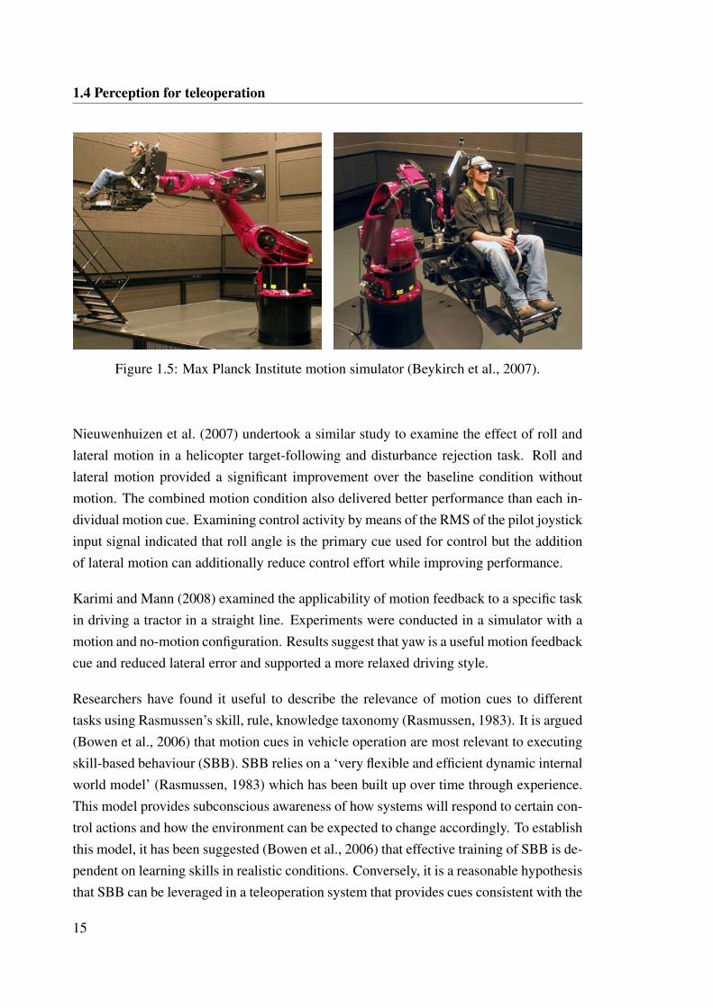
Beykirch et al. (2007) employed a novel motion simulator based on a robotic arm (seeFigure 1.5) to replicate aspects of the experiments of Schroeder (1998). Results obtainedindicated that reducing from full to less motion scaling in roll and lateral motion increasedthe magnitude of control inputs, a consequence of the need to generate lead from the visualinformation rather than the motion cues. This finding was consistent with Schroeder(1998). However, in results contradictory to Schroeder (1998), the no motion baselineshowed a decrease in joystick input magnitude and rate. For lateral hover stabilisation,the experimental results indicated that reducing motion scaling prevented the task frombeing performed effectively but when all motion was removed, the task performance wasonly marginally worse than with full motion feedback. The authors comment that thedifferences observed in the results from Schroeder (1998) may be due to the use of non-professional pilots being used in the study.
14
1.4 Perception for teleoperation
Figure 1.5: Max Planck Institute motion simulator (Beykirch et al., 2007).
Nieuwenhuizen et al. (2007) undertook a similar study to examine the effect of roll andlateral motion in a helicopter target-following and disturbance rejection task. Roll andlateral motion provided a significant improvement over the baseline condition withoutmotion. The combined motion condition also delivered better performance than each in-dividual motion cue. Examining control activity by means of the RMS of the pilot joystickinput signal indicated that roll angle is the primary cue used for control but the additionof lateral motion can additionally reduce control effort while improving performance.
Karimi and Mann (2008) examined the applicability of motion feedback to a specific taskin driving a tractor in a straight line. Experiments were conducted in a simulator with amotion and no-motion configuration. Results suggest that yaw is a useful motion feedbackcue and reduced lateral error and supported a more relaxed driving style.
Researchers have found it useful to describe the relevance of motion cues to differenttasks using Rasmussen’s skill, rule, knowledge taxonomy (Rasmussen, 1983). It is argued(Bowen et al., 2006) that motion cues in vehicle operation are most relevant to executingskill-based behaviour (SBB). SBB relies on a ‘very flexible and efficient dynamic internalworld model’ (Rasmussen, 1983) which has been built up over time through experience.This model provides subconscious awareness of how systems will respond to certain con-trol actions and how the environment can be expected to change accordingly. To establishthis model, it has been suggested (Bowen et al., 2006) that effective training of SBB is de-pendent on learning skills in realistic conditions. Conversely, it is a reasonable hypothesisthat SBB can be leveraged in a teleoperation system that provides cues consistent with the
15
1.4 Perception for teleoperation
internal world model.
Despite extensive research over many decades, there still remains uncertainty regardingthe precise behaviour and characteristics of the human vestibular system, particularly asexcitation dynamics grow in complexity and other factors impose mental loading. Thedifficulty in accurately modeling the human has many facets. As Hosman and van derVaart (1981) comment, investigation is difficult due to the fact that there is redundancyin sensory information as proven by the fact that sensory defective persons can learn tocompensate with other sensors. Further complicating any assessment of the interactionbetween sensory information is the fact that there are neural processes that are responsiblefor resolving and fusing this information. For example, Merfeld et al. (1999) performeda study involving providing subjects with a false sense of linear acceleration by rotatingand then tilting subjects. It was found that the eyes moved as would be expected if a truelinear acceleration existed indicating that an internal model had been used to process theambiguous sensory information. The fact that the vestibular system and its interactionwith other sensory systems is not completely understood makes it difficult to identifyrequirements around motion feedback for a given task and vehicle.
Across the literature, there is general agreement that different tasks place different re-quirements on levels of fidelity and range of motion cues. Complicating any investigation,however, is the fact that different people potentially use cues in different ways. Findingsrelated to how humans use internal models to resolve ambiguous information and improvetheir perception accuracy would appear to suggest that motion feedback applied to assistteleoperation should target maximum realism. Related to this also is the suggestion thatthe internal dynamic model is a key aspect of utilising SBB. However, the findings ofRingland et al. (1971), that a subset of motion cues provided higher performance than thefull complement of motion cues, are at odds with the general hypothesis that situationalrealism should enable better utilisation of SBB. Even though this study was performedwith a simulator and idealised visual cues, this result does provoke consideration in thecontext of a teleoperation system of whether cues that are experienced on board mayactually have a negative influence on performance.
The application of motion feedback to assist specifically with teleoperation is a relativelynew field of investigation. Ortiz et al. (2008) applied motion feedback to assist with oper-ation of an Unmanned Ground Vehicle (UGV). Task completion time was not improvedby motion feedback for a ‘follow the path’ exercise that included negotiation of a narrow
16
1.4 Perception for teleoperation
tabletop type ramp. Giordano et al. (2010) examined the potential for scaled feedback ofthe gravity vector to assist with a UAV movement and hovering task. Results based ontask completion time indicated that motion feedback of this type provided no improve-ment against the task performed with visual information only. However, control effort asmeasured by the average magnitude of control input over all trials was lower with motionfeedback. While the influence of motion feedback on performance in these circumstancepermits an interesting assessment of teleoperator performance, it is fundamentally dif-ferent from the objective of supporting teleoperation of equipment for which operatorsalready have skill based behaviour learnt through on board operational experience. It isimportant to note that these experiments were performed with vehicles that cannot be op-erated on board. Consequently, it might be suggested that subjects responded to motioncues based on instinct and some learnt behaviour rather than according to true operationalexperience.
In the context of this study, it would appear that although accurate motion cues should betargeted, their benefit can only be assessed through experiments. The ability to modifymotion feedback cues independently would thus appear to be a key one.
1.4.6 Assessing perception requirements
As the previous sections reveal, there is a well developed field of research around per-ception as well as its impact on teleoperation. An examination of the literature indicatesthat there is still significant unresolved understanding regarding what factors are criticalto teleoperation and how perception characteristics might best be defined to improve per-formance. These gaps in understanding are both a result of the complexity and difficultyassociated with examining the characteristics of human sensory systems and also the lackof studies performed on diverse vehicle types. The complex relationship between per-ception and performance makes it difficult to predict in a non-trivial and accurate wayhow altering the perception characteristics of a teleoperation system may influence taskperformance.
A review of the broad applications of teleoperation reveals that the factors that are criti-cal to perception and performance vary depending on the machine under control and thenature of the task. This is perhaps intuitive but does not necessarily simplify the processof determining which factors are important for a given application and task without ex-perimentation. Nevertheless, there are some clearly consistent findings across multiplestudies. Time delay is a major determinant of performance, with minimum time delay de-
17
1.4 Perception for teleoperation
sirable. Different sensory systems can dominate at different stages in a task. It is possibleto substitute information that would traditionally be obtained through one sensory systemby exciting another sensory system in an intuitive way. While knowledge of these factorscan assist in the design of a novel teleoperation systems it is insufficient to describe ageneric implementation that will achieve optimal performance. Lathan and Tracey (2002)caution that ‘because of the differences between individual operators, designing an inter-face between the human operator and a teleoperated robot presents a unique challenge’.They go on to suggest that there may be a requirement to customise control and feedbackinterfaces to specific user needs. While this may be true, it is clearly desirable to be ableto determine a base perception configuration that is useful to most operators.
Weir and McRuer (1968) posited that there are two alternate approaches to determiningthe closed-loop structure of a driver-vehicle system: from a perception basis and from aguidance and control theory basis. The issue with the perception approach is that it canbe an involved and difficult exercise. The issue with the formulation as a guidance andcontrol problem is that there is no unique solution. Weir and McRuer (1968) suggest thatthe best approach is to marry the two.
The methodology to be followed in this study is predominantly aligned to the perceptionapproach. The control side of the teleoperation system is unaltered. This methodologytakes significant inspiration from the approach of Ross et al. (2008). Ross et al. (2008)developed a high-fidelity teleoperation system for an unmanned ground vehicle to per-mit the independent variation of latency, resolution, field of view, frame-rate and motion.The high-fidelity teleoperation system provided an experimental apparatus that permittedbroad testing of multiple perception factors on teleoperator performance. The experimen-tal task involved the operator navigating the vehicle over unstructured terrain to reacha goal. Experiments revealed latency to be highly detrimental to performance and useracceptance, with latencies greater than 400-500 ms considered particularly severe. In aportion of testing where operators could select their own perception characteristics withincertain bandwidth constraints, it was noticed that during regular driving, high frame-rate,wide field of view and medium resolution was preferred while during navigation of com-plex environments and route planning, there was a preference for high resolution, com-promising on field of view and frame-rate. Motion and audio cues were found to supportsensation of realism and presence.
The apparatus developed by Ross et al. (2008) permitted highly targeted testing of the
18
1.5 Thesis overview
role of perception. Using this methodology, the component of the system responsiblefor the provision of perception is capable of being modified independently, i.e. there isfull control over the ‘filtering’ characteristics of the perception system. It is possible inprinciple to examine factors which influence teleoperation performance for any task, anyremote control implementation and even any controlled element.
Experimentally, this study is believed to be novel in the sense that there is no simulationand the application of teleoperation uses a vehicle for which existing operators are ex-pected to have extensive on board operating experience. This is in contrast to previousstudies where the influence of different factors on performance have been examined byusing a simulator or the vehicle being teleoperated is not designed for on board opera-tion. While simulators greatly simplify experimentation, it is difficult to capture all of thedisturbances that are introduced in a live system. Furthermore, as noted by Nagai et al.(2002), the performance of an operator can be significantly influenced by the urgency andperceived consequences of a real task as compared with a simulated task.
The focus on a vehicle that can be operated on board rather than a UAV or UGV allowsfor the exploitation of operators with operational experience and learnt SBB. It is believedthat this will provide for a more direct evaluation of the influence of introducing a tele-operation system and how the changes it brings to the human-vehicle dynamics might beminimised.
1.5 Thesis overview
This thesis seeks to present a structured investigation of the perception requirements foreffective bulldozer teleoperation. This chapter has highlighted the motivation for achiev-ing high performance teleoperation of bulldozers based on safety and productivity con-cerns. Sheridan’s concept of perception ‘filtering’ in teleoperation was discussed andintroduced as the guiding theoretical context for this study.
In Chapter 2, the aims and methodology of the study are introduced. A two part procedureis proposed involving experimental evaluation and task analysis.
Chapter 3 presents the experimental evaluation of the influence of different perceptioncues on the performance of the bulldozer teleoperator. The notion of performance isgiven resolution by considering multiple aspects including: task completion time, taskprogress and workload.
19
1.5 Thesis overview
Chapter 4 presents a task analysis informed by the experimental results. The task analysisincorporates findings from the experimental evaluation, additional qualitative feedbackobtained from operators and task observation.
An attempt is made in Chapter 5 to consolidate the results presented in Chapters 3 and 4.The influence of the various perception cues is discussed and ranked according to theirinfluence on bulldozer teleoperation performance.
Chapter 6 concludes the thesis by summarising the contributions made and proposed areasof further investigation.
20
CHAPTER 2
Examining perception requirements forteleoperation
2.1 Aim
The literature reviewed in Chapter 1 reveals that there is no clear generic method fordetermining perception requirements of a given mechanism under teleoperation. Never-theless, the theoretical concept of the teleoperation system acting as a filtering element inthe control loop of the operator and the equipment under control provides a sound contextfor experimental evaluation.
This thesis aims to determine: What feedback attributes are critical to maximising bull-
dozer teleoperation performance and user acceptance? To answer this question throughexperimental evaluation, there are five key steps:
1. Evaluate the degree of performance degradation associated with bulldozer teleop-
eration compared to on board operation.
2. Evaluate the potential for motion feedback to improve performance and user ac-
ceptance in bulldozer teleoperation.
3. Evaluate the potential for enhanced visual and audio quality to improve perfor-
mance and user acceptance in bulldozer teleoperation.
4. Evaluate the potential for task focused visualisation to improve performance and
user acceptance in bulldozer teleoperation.
21
2.2 Methodology
5. Determine when the various feedback modalities are most relevant to particular
bulldozer control activities.
Execution of the above steps provides a robust appreciation of the influence of feedbackcues on bulldozer teleoperation in both a specific and general sense. Achieving the aimof this thesis makes a contribution to the state-of-the-art of bulldozer teleoperation sys-tems by providing key knowledge necessary for effective perception system design. It ishoped that a secondary contribution of this thesis is in the advancement of methodologiesfor identifying and determining perception cues critical to teleoperation systems moregenerally.
2.2 Methodology
This thesis employs an experimental approach to test the hypothesis that enhanced per-ception can improve performance and user acceptance. The theoretical context for thisapproach involves framing the bulldozer teleoperation system as a filtering element in thefeedback pathway.
The experimental approach relies on the specification of baseline perception character-istics which will provide the reference point against which the influence of perceptionenhancements can be evaluated. A logical baseline is provided by the default perceptionconfiguration of an existing non-line-of-sight bulldozer teleoperation system.
The baseline teleoperation system is subsequently modified to allow its perception char-acteristics to be altered. This aspect of the methodology takes strong influences from theapproach employed by Ross et al. (2008).
The modification of the baseline system is achieved through the integration of an en-hanced perception cell: a collection of additional hardware that provides experimentalcontrol over the perception characteristics but leaves the baseline perception configura-tion and the control mechanism of the system unaltered. This allows experimentation tosolely concentrate on the influence of perception feedback and maintains a meaningfulbaseline reference configuration.
The enhanced perception cell provides the basis for experiments that are designed to iso-late the influence of enhanced perception generally as well as the distinct influence ofspecific feedback cues.
22
2.2 Methodology
The key steps of the methodology are summarised below.
1. Develop and integrate the enhanced perception cell.
The enhanced perception cell supports experimental evaluation by allowing for thesimple addition or removal of specific feedback paths that are to be investigated.The feedback cues provided by the enhanced perception cell are selected based ontheir relevance to the tasks associated with bulldozer operation. The fidelity andtimeliness of these cues can be modified independently, thus permitting controlledadjustment of the ‘filtering’ characteristics of the teleoperation system.
The enhanced perception cell is integrated with a conventional bulldozer teleop-eration system. The perception characteristics of this conventional teleoperationsystem will provide the baseline against which perception enhancements are evalu-ated.
2. Establish the experimental procedure.
A typical bulldozer operational task is selected as the basis for experimental evalu-ation using the enhanced perception cell. The task should be representative of themain elements of bulldozer operation.
A secondary consideration is the requirement that the task be sufficiently structuredso as to minimise inconsistencies in performance and variability in results.
3. Execute the experimental plan.
The enhanced perception cell provides the means to independently vary the percep-tion characteristics of the teleoperation system. Experiments are conducted with thecell to evaluate the effect of different perception characteristics on task performanceand user acceptance.
Multiple metrics are logged during the execution of experiments to enable a detailedanalysis of performance and operator behaviour. In addition, qualitative feedbackis obtained from the operator around perceived performance and workload.
4. Isolate influence of various perception cues.
The results obtained from the experiments are analysed to first prove or disprovethe hypothesis that enhanced perception can improve performance in teleoperation.Second, the relative contribution of individual factors on performance and user ac-ceptance will be identified.
23
2.3 Perception cues relevant to bulldozer operation
5. Associate task aspects with perception requirements.
The experimental results are consolidated with qualitative feedback and task analy-sis to associate perception requirements with the task elements and control aspectsof operating a bulldozer.
The methodology summarised above is devised such that there is a degree of separationbetween the approach and the specific system under investigation. The intent is to notonly facilitate investigation of the perception requirements for bulldozer teleoperation butalso to validate the methodology as a more general approach to teleoperation perceptionrequirements assessment.
2.3 Perception cues relevant to bulldozer operation
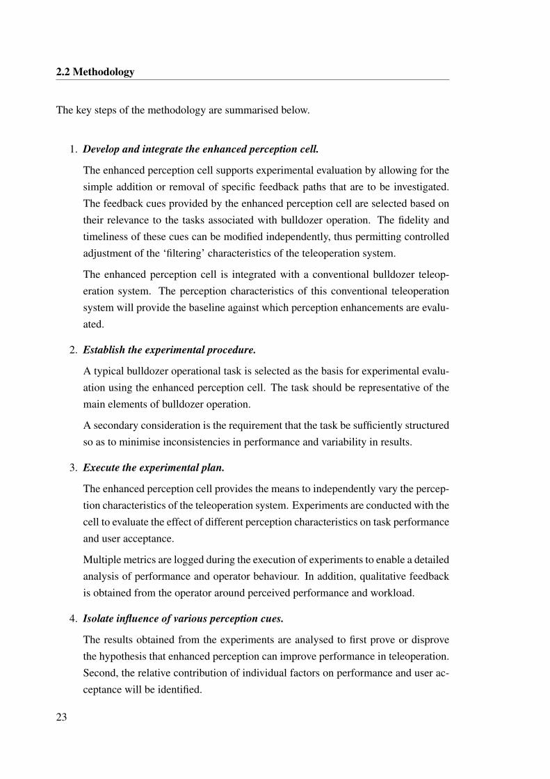
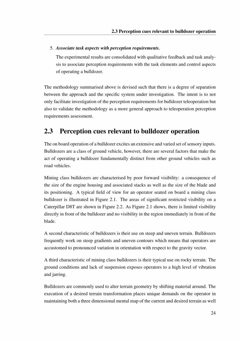
The on board operation of a bulldozer excites an extensive and varied set of sensory inputs.Bulldozers are a class of ground vehicle, however, there are several factors that make theact of operating a bulldozer fundamentally distinct from other ground vehicles such asroad vehicles.
Mining class bulldozers are characterised by poor forward visibility: a consequence ofthe size of the engine housing and associated stacks as well as the size of the blade andits positioning. A typical field of view for an operator seated on board a mining classbulldozer is illustrated in Figure 2.1. The areas of significant restricted visibility on aCaterpillar D8T are shown in Figure 2.2. As Figure 2.1 shows, there is limited visibilitydirectly in front of the bulldozer and no visibility in the region immediately in front of theblade.
A second characteristic of bulldozers is their use on steep and uneven terrain. Bulldozersfrequently work on steep gradients and uneven contours which means that operators areaccustomed to pronounced variation in orientation with respect to the gravity vector.
A third characteristic of mining class bulldozers is their typical use on rocky terrain. Theground conditions and lack of suspension exposes operators to a high level of vibrationand jarring.
Bulldozers are commonly used to alter terrain geometry by shifting material around. Theexecution of a desired terrain transformation places unique demands on the operator inmaintaining both a three dimensional mental map of the current and desired terrain as well
24
2.3 Perception cues relevant to bulldozer operation
Figure 2.1: View from inside bulldozer cab.
12m
FWD
Figure 2.2: Shaded region indicates area of significantly restricted visibility on a Cater-pillar D8T. (Caterpillar, 2009)
as their position and orientation within this reference frame. This requires a high degreeof contextual awareness, loosely akin to the requirements on a pilot when skywriting.
The mining environment also introduces unique challenges around contour and objectperception. Bulldozers in a mining context typically operate in expansive areas of eithercomponent or loosely disturbed dirt and/or rock. These conditions mean that there is verylittle contrast and terrain contours and individual terrain features can be very difficult to
25
2.4 Feedback factors for experimental evaluation
perceive. However, the act of disturbing the ground can actually improve environmentperception by exposing material with differing moisture content and hence colouration.
Bulldozer operation is also distinguished by the fact that the terrain may be actively alteredas the bulldozer moves over it. There is thus a strong correlation between the controloutputs of the operator and the motion response of the bulldozer.
In addition to this relationship between control decisions and the motion response, bull-dozer operators are also exposed to the acoustic response of the drives which has a strongcorrelation with machine loading. The acoustic response can inform the operator of theneed to make a control adjustment to modulate the loading on the machine. This is simi-lar to making a gear or acceleration adjustment in a manual car based on the pitch of theengine whine.
These various characteristics of bulldozer operation reveal that multiple sensory systemsplay a role in achieving effective control. Removing the operator from the machine andplacing them in a teleoperation system severs these direct feedback pathways. The tele-operation perception system must reconnect some or all of these pathways or otherwisemeet feedback requirements to enable the operator to leverage their learnt skills whenoperating remotely.
Based on the unique characteristics of bulldozer operation, the cues that appear to be mostrelevant to effective operation are vision, motion, audio and contextual awareness.
2.4 Feedback factors for experimental evaluation
The cues theorised to be most relevant to on board bulldozer operation (vision, motion,audio and contextual awareness) are selected as the main feedback groupings for experi-mental evaluation. The specific factors that are explored within each of these perceptiongroupings are justified below.
2.4.1 Vision
The key challenges in replicating the visual cues available to the operator on board arein providing adequate field of view, resolution, contrast, depth perception and latency.Complicating the provision of vision remotely are technology limitations that introducecertain constraints on the fidelity and timeliness of video streams over a wireless network.
26
2.4 Feedback factors for experimental evaluation
The limited forward visibility from within the cab forces operators to make use of a num-ber of quite subtle visual cues. For example, due to the inability to directly observe howmaterial is building up against the blade, operators look for signs of a fully loaded bladevia the presence of material above the top edge of the blade. However, it can be difficultto distinguish the material appearing at the top edge of the blade from the background ter-rain. The amount of material observed flowing around the side of the blade also providesan indication of loading. The consistency and moisture content of the material can also beinterpreted from the colouration and movement of material around the blade. Perceptionof this motion is reliant on the ability to distinguish between the flowing material and thestationary terrain.
The lack of contrast typical of the mining environment terrain is a challenge for the onboard operator as well as for the teleoperator. A confounding factor is the typically poorperformance of video capture in low contrast environments. Furthermore, the capture of athree dimensional terrain and features and its display on a two dimensional screen greatlyreduces the ability of the teleoperator to perceive contours and geometry.
The subtlety of these various cues suggests potential value in high resolution video in theteleoperation station. Also, the potential benefits of depth perception in resolving thesesubtle cues also suggest value in capture and display in 3D.
2.4.2 Motion
A commonly held opinion among bulldozer operators is that the limited visibility avail-able elevates the relevance and value of motion cues. The lack of forward visibility leadsto the operator also relying on motion cues to detect variation in loading of the blade. Forexample, deep cutting will pull the bulldozer down. Uneven lateral cutting will pull oneside of the bulldozer down. The operator’s modulation of blade movements to achieveconsistent fill and grade relies on these sensations.
Vision and motion both interact to support the operator’s appreciation of terrain geometry.The roll and pitch orientation of the bulldozer as sensed at the operator seat provides anindication of the relative grade/slope. The motion of the bulldozer as it traverses over theterrain provides information that allows the operator to perceive the overall contour of thework area and update their internal model. This becomes a key component of contextualawareness, discussed later in this section.
27
2.4 Feedback factors for experimental evaluation
In traversing uneven terrain, experienced operators will employ special tactics to preventrapid see-sawing and impacts on the bulldozer. At the top of a distinct rise, operatorswill typically command a direction change when they sense they have reached the tippingpoint of the bulldozer to help ease off the rise. A similar motion cue is provided incircumstance when the operator is pushing material over an edge. Change in balance ofthe bulldozer is sensed indicating the need to begin reversing.
Vibration is also constantly present throughout bulldozer operation. The vibration re-sponse of the bulldozer holds cues relating to machine loading as well as material re-sponse. A commonly encountered phenomenon in bulldozing is track slip. Track slipoccurs when the bulldozer loses traction causing the tracks to dig into the ground insteadof propelling the bulldozer forward. The occurrence of track slip is marked by a uniquevibration response.
The vibration response of the bulldozer varies according to material conditions, provid-ing information about expected diggability and material flow behaviour. For example,soft/wet material would dampen the vibrations felt in the cab, whereas rocky terrain wouldcause a greater magnitude of vibrations.
Translational acceleration is felt by the operator based on the direction and speed of travel.Slight deceleration while pushing/cutting may indicate bogging down and excessive load-ing of the blade. Slight acceleration while pushing/cutting may indicate undesired releaseof material. Such cues provide key feedback pathways for throttle and directional control.
This wide range of motion cues available to the operator on board indicates potentialvalue in partial or full replication of bulldozer motion at the teleoperation station. Thevariety of motion cues would appear to demand the ability to provide a comprehensiverange of motion replication for experimental evaluation. In addition, there is the necessaryrequirement to be able to isolate individual motion cues.
2.4.3 Audio
The sounds the operator hears on board the bulldozer provide corroborating evidence forother perceived cues. For example, the presence of track slip may be detected by sightand the vibratory response as well as by interpreting the sounds made by the tracks.
The loading on the engine and drive are also detectable through the audio signal. The pitchof the whine of the drive is proportional to the level of loading. For example, the pitch of
28
2.4 Feedback factors for experimental evaluation
the whine will be low when loading is high as more power is required. Conversely, thepitch of the whine will go up as the loading is released and less power is required.
The provision of audio is a suitable feedback factor for evaluation and comparativelysimple to implement. Nevertheless, the various audio cues described are again quite subtleand require a relatively high quality audio stream to accurately replicate.
2.4.4 Contextual awareness
Many of the aforementioned cues are inputs to the operator’s internal model/map of thework area. As discussed in Section 2.3, bulldozing tasks typically involve gross terraintransformation. This means that the work area is constantly changing and the abilityof the operator to maintain an accurate internal map and orient and position themselveswithin this environment is paramount. Contextual awareness is also important for safety,particularly if the work area contains or is near to other pieces of equipment and plant.
The contextual awareness of the teleoperator is fundamentally challenged by the inabilityto stop and take stock of the environment by looking around in all directions. Alterna-tive methods for providing contextual awareness are required. The proposed method forevaluation of the influence of contextual awareness is through the provision of a visualisa-tion that displays terrain geometry and the pose of the bulldozer within a fixed referenceframe.
2.4.5 Summary of feedback factors to be evaluated
The contextualisation of the teleoperation system as a ‘filtering’ element suggests thatreducing the disparity between on board perception and remote perception may deliverimprovements in terms of performance and user acceptance. The selection of feedbackfactors for experimental evaluation represents the pathways for which adjustment of the‘filtering’ characteristics are to be explored.
Based on the perception cues hypothesised to be most relevant to bulldozer operation, thefeedback factors selected for experimental evaluation are:
1. Visual resolution
2. Visual depth perception
29

2.4 Feedback factors for experimental evaluation
3. Presence of audio
4. Motion feedback incorporating gross orientation variation, vibration, and transla-tional acceleration
5. Contextual awareness through visualisation of terrain geometry and bulldozer pose
The enhanced perception cell will allow the baseline perception configuration to be aug-mented in terms of these various factors. A key requirement for experimentation is toallow these cues to be tested with a degree of independence such that the individual effectof the various cues might be isolated.
30
CHAPTER 3
Experimental evaluation of perceptionrequirements
3.1 Aim
This chapter summarises the experimental evaluation of the influence on bulldozer teleop-eration of the feedback factors identified in Section 2.4.5. The aim of these experimentswas to determine what feedback attributes are critical to maximising performance anduser acceptance.
The experimental approach is based on establishing control over the perception charac-teristics of the teleoperation system and examining the effect of varying these character-istics. A conventional non-line-of-sight teleoperation system was selected as a baselineperception configuration. Augmentations on this baseline perception configuration wereexamined through the application of the developed apparatus, termed the enhanced per-ception cell. The enhanced perception cell enables independent control over the targetedfeedback factors.
3.2 The conventional teleoperation system
A Caterpillar D8T (see Figure 3.1a) was used as the remotely controlled bulldozer. TheD8T was paired with a remote station configured for non-line-of-sight teleoperation.
The remote station provided visual feedback through a live stream of a combination offorward views and one rear view. An image of the typical operator interface at the remote
31
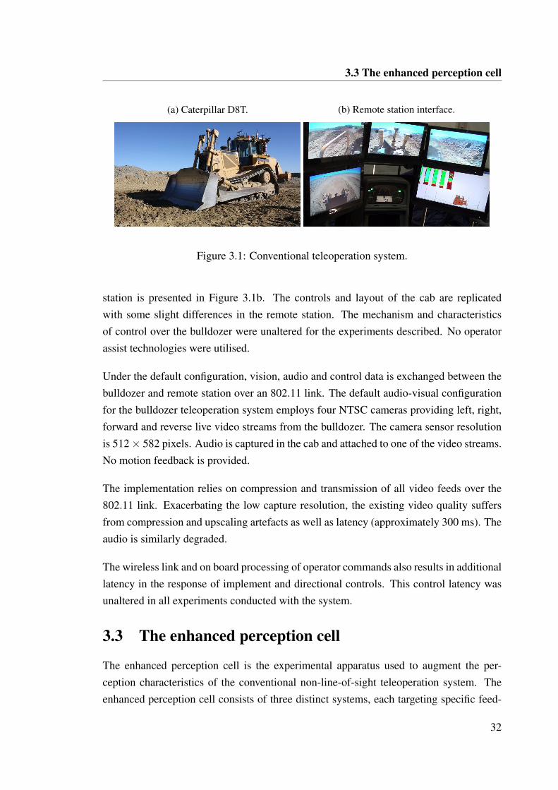
3.3 The enhanced perception cell
(a) Caterpillar D8T. (b) Remote station interface.
Figure 3.1: Conventional teleoperation system.
station is presented in Figure 3.1b. The controls and layout of the cab are replicatedwith some slight differences in the remote station. The mechanism and characteristicsof control over the bulldozer were unaltered for the experiments described. No operatorassist technologies were utilised.
Under the default configuration, vision, audio and control data is exchanged between thebulldozer and remote station over an 802.11 link. The default audio-visual configurationfor the bulldozer teleoperation system employs four NTSC cameras providing left, right,forward and reverse live video streams from the bulldozer. The camera sensor resolutionis 512 × 582 pixels. Audio is captured in the cab and attached to one of the video streams.No motion feedback is provided.
The implementation relies on compression and transmission of all video feeds over the802.11 link. Exacerbating the low capture resolution, the existing video quality suffersfrom compression and upscaling artefacts as well as latency (approximately 300 ms). Theaudio is similarly degraded.
The wireless link and on board processing of operator commands also results in additionallatency in the response of implement and directional controls. This control latency wasunaltered in all experiments conducted with the system.
3.3 The enhanced perception cell
The enhanced perception cell is the experimental apparatus used to augment the per-ception characteristics of the conventional non-line-of-sight teleoperation system. Theenhanced perception cell consists of three distinct systems, each targeting specific feed-
32
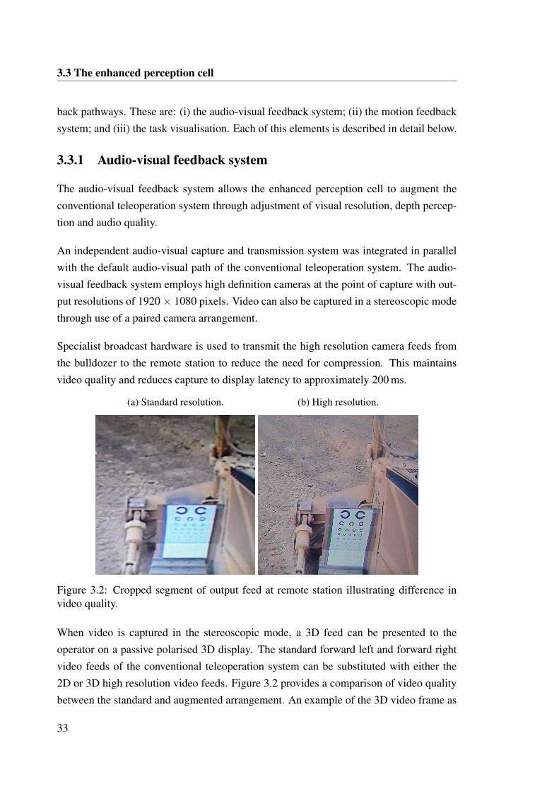
3.3 The enhanced perception cell
back pathways. These are: (i) the audio-visual feedback system; (ii) the motion feedbacksystem; and (iii) the task visualisation. Each of this elements is described in detail below.
3.3.1 Audio-visual feedback system
The audio-visual feedback system allows the enhanced perception cell to augment theconventional teleoperation system through adjustment of visual resolution, depth percep-tion and audio quality.
An independent audio-visual capture and transmission system was integrated in parallelwith the default audio-visual path of the conventional teleoperation system. The audio-visual feedback system employs high definition cameras at the point of capture with out-put resolutions of 1920 × 1080 pixels. Video can also be captured in a stereoscopic modethrough use of a paired camera arrangement.
Specialist broadcast hardware is used to transmit the high resolution camera feeds fromthe bulldozer to the remote station to reduce the need for compression. This maintainsvideo quality and reduces capture to display latency to approximately 200 ms.
(a) Standard resolution. (b) High resolution.
Figure 3.2: Cropped segment of output feed at remote station illustrating difference invideo quality.
When video is captured in the stereoscopic mode, a 3D feed can be presented to theoperator on a passive polarised 3D display. The standard forward left and forward rightvideo feeds of the conventional teleoperation system can be substituted with either the2D or 3D high resolution video feeds. Figure 3.2 provides a comparison of video qualitybetween the standard and augmented arrangement. An example of the 3D video frame as
33
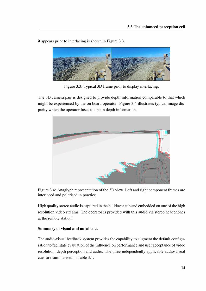
3.3 The enhanced perception cell
it appears prior to interlacing is shown in Figure 3.3.
Figure 3.3: Typical 3D frame prior to display interlacing.
The 3D camera pair is designed to provide depth information comparable to that whichmight be experienced by the on board operator. Figure 3.4 illustrates typical image dis-parity which the operator fuses to obtain depth information.
Figure 3.4: Anaglyph representation of the 3D view. Left and right component frames areinterlaced and polarised in practice.
High quality stereo audio is captured in the bulldozer cab and embedded on one of the highresolution video streams. The operator is provided with this audio via stereo headphonesat the remote station.
Summary of visual and aural cues
The audio-visual feedback system provides the capability to augment the default configu-ration to facilitate evaluation of the influence on performance and user acceptance of videoresolution, depth perception and audio. The three independently applicable audio-visualcues are summarised in Table 3.1.
34
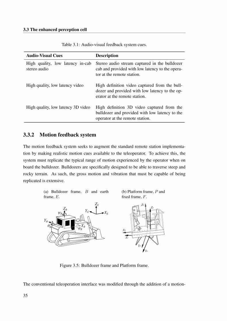
3.3 The enhanced perception cell
Table 3.1: Audio-visual feedback system cues.
Audio-Visual Cues Description
High quality, low latency in-cabstereo audio
Stereo audio stream captured in the bulldozercab and provided with low latency to the opera-tor at the remote station.
High quality, low latency video High definition video captured from the bull-dozer and provided with low latency to the op-erator at the remote station.
High quality, low latency 3D video High definition 3D video captured from thebulldozer and provided with low latency to theoperator at the remote station.
3.3.2 Motion feedback system
The motion feedback system seeks to augment the standard remote station implementa-tion by making realistic motion cues available to the teleoperator. To achieve this, thesystem must replicate the typical range of motion experienced by the operator when onboard the bulldozer. Bulldozers are specifically designed to be able to traverse steep androcky terrain. As such, the gross motion and vibration that must be capable of beingreplicated is extensive.
(a) Bulldozer frame, B and earthframe, E.
XB
YB
ZBψB
θB φB
XE
ZE
YE
(b) Platform frame, P andfixed frame, F .
YP
ZP
XP
YF
ZF
XF
Figure 3.5: Bulldozer frame and Platform frame.
The conventional teleoperation interface was modified through the addition of a motion-
35
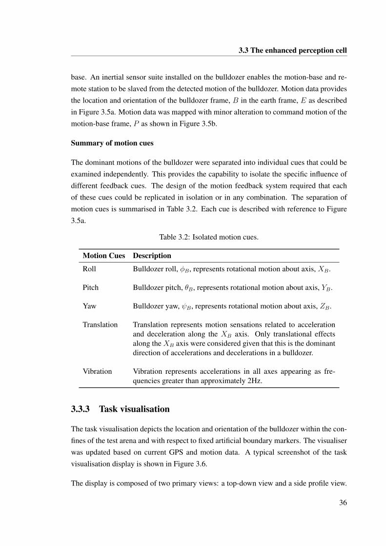
3.3 The enhanced perception cell
base. An inertial sensor suite installed on the bulldozer enables the motion-base and re-mote station to be slaved from the detected motion of the bulldozer. Motion data providesthe location and orientation of the bulldozer frame, B in the earth frame, E as describedin Figure 3.5a. Motion data was mapped with minor alteration to command motion of themotion-base frame, P as shown in Figure 3.5b.
Summary of motion cues
The dominant motions of the bulldozer were separated into individual cues that could beexamined independently. This provides the capability to isolate the specific influence ofdifferent feedback cues. The design of the motion feedback system required that eachof these cues could be replicated in isolation or in any combination. The separation ofmotion cues is summarised in Table 3.2. Each cue is described with reference to Figure3.5a.
Table 3.2: Isolated motion cues.
Motion Cues Description
Roll Bulldozer roll, φB, represents rotational motion about axis, XB.
Pitch Bulldozer pitch, θB, represents rotational motion about axis, YB.
Yaw Bulldozer yaw, ψB, represents rotational motion about axis, ZB.
Translation Translation represents motion sensations related to accelerationand deceleration along the XB axis. Only translational effectsalong the XB axis were considered given that this is the dominantdirection of accelerations and decelerations in a bulldozer.
Vibration Vibration represents accelerations in all axes appearing as fre-quencies greater than approximately 2Hz.
3.3.3 Task visualisation
The task visualisation depicts the location and orientation of the bulldozer within the con-fines of the test arena and with respect to fixed artificial boundary markers. The visualiserwas updated based on current GPS and motion data. A typical screenshot of the taskvisualisation display is shown in Figure 3.6.
The display is composed of two primary views: a top-down view and a side profile view.
36
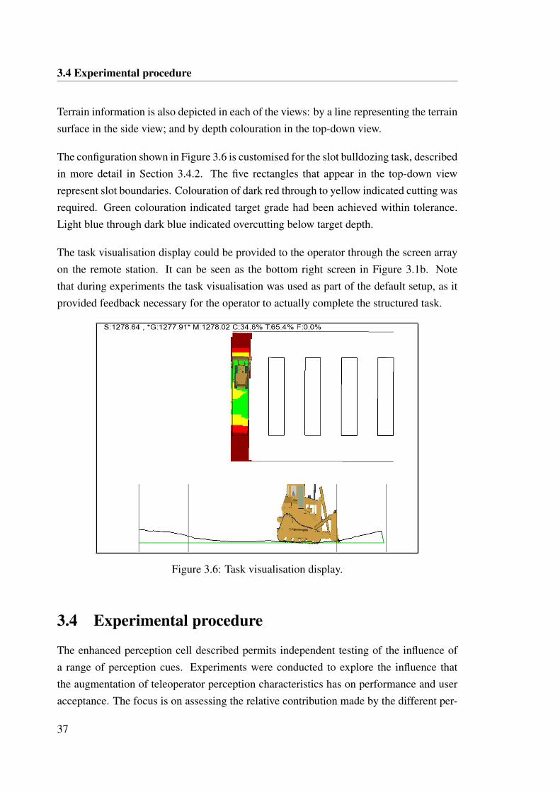
3.4 Experimental procedure
Terrain information is also depicted in each of the views: by a line representing the terrainsurface in the side view; and by depth colouration in the top-down view.
The configuration shown in Figure 3.6 is customised for the slot bulldozing task, describedin more detail in Section 3.4.2. The five rectangles that appear in the top-down viewrepresent slot boundaries. Colouration of dark red through to yellow indicated cutting wasrequired. Green colouration indicated target grade had been achieved within tolerance.Light blue through dark blue indicated overcutting below target depth.
The task visualisation display could be provided to the operator through the screen arrayon the remote station. It can be seen as the bottom right screen in Figure 3.1b. Notethat during experiments the task visualisation was used as part of the default setup, as itprovided feedback necessary for the operator to actually complete the structured task.
Figure 3.6: Task visualisation display.
3.4 Experimental procedure
The enhanced perception cell described permits independent testing of the influence ofa range of perception cues. Experiments were conducted to explore the influence thatthe augmentation of teleoperator perception characteristics has on performance and useracceptance. The focus is on assessing the relative contribution made by the different per-
37
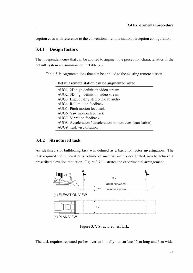
3.4 Experimental procedure
ception cues with reference to the conventional remote station perception configuration.
3.4.1 Design factors
The independent cues that can be applied to augment the perception characteristics of thedefault system are summarised in Table 3.3.
Table 3.3: Augmentations that can be applied to the existing remote station.
Default remote station can be augmented with:
AUG1. 2D high definition video streamAUG2. 3D high definition video streamAUG3. High quality stereo in-cab audioAUG4. Roll motion feedbackAUG5. Pitch motion feedbackAUG6. Yaw motion feedbackAUG7. Vibration feedbackAUG8. Acceleration / deceleration motion cues (translation)AUG9. Task visualisation
3.4.2 Structured task
An idealised slot bulldozing task was defined as a basis for factor investigation. Thetask required the removal of a volume of material over a designated area to achieve aprescribed elevation reduction. Figure 3.7 illustrates the experimental arrangement.
START ELEVATION
TARGET ELEVATION0.8m
A B
15m
3m
(a) ELEVATION VIEW
(b) PLAN VIEW
Figure 3.7: Structured test task.
The task requires repeated pushes over an initially flat surface 15 m long and 3 m wide.
38
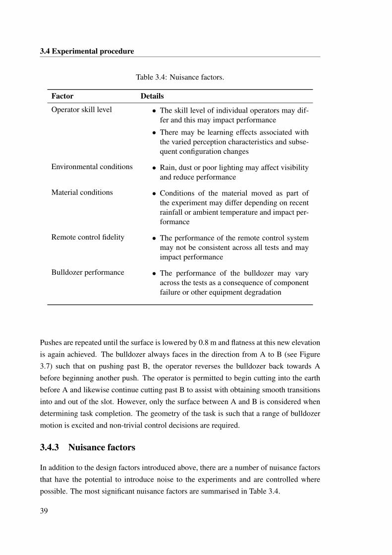
3.4 Experimental procedure
Table 3.4: Nuisance factors.
Factor Details
Operator skill level • The skill level of individual operators may dif-fer and this may impact performance
• There may be learning effects associated withthe varied perception characteristics and subse-quent configuration changes
Environmental conditions • Rain, dust or poor lighting may affect visibilityand reduce performance
Material conditions • Conditions of the material moved as part ofthe experiment may differ depending on recentrainfall or ambient temperature and impact per-formance
Remote control fidelity • The performance of the remote control systemmay not be consistent across all tests and mayimpact performance
Bulldozer performance • The performance of the bulldozer may varyacross the tests as a consequence of componentfailure or other equipment degradation
Pushes are repeated until the surface is lowered by 0.8 m and flatness at this new elevationis again achieved. The bulldozer always faces in the direction from A to B (see Figure3.7) such that on pushing past B, the operator reverses the bulldozer back towards Abefore beginning another push. The operator is permitted to begin cutting into the earthbefore A and likewise continue cutting past B to assist with obtaining smooth transitionsinto and out of the slot. However, only the surface between A and B is considered whendetermining task completion. The geometry of the task is such that a range of bulldozermotion is excited and non-trivial control decisions are required.
3.4.3 Nuisance factors
In addition to the design factors introduced above, there are a number of nuisance factorsthat have the potential to introduce noise to the experiments and are controlled wherepossible. The most significant nuisance factors are summarised in Table 3.4.
39
3.4 Experimental procedure
3.4.4 Experimental Controls
During experimentation, effort was taken to maintain consistent material conditions. Vari-ation in moisture content influences the traction of the bulldozer as well as the degree towhich material will bind and roll when cut. Consistent moisture content is also importantin terms of minimising dust that would in turn obstruct vision.
Pre-experimental trials also highlighted a significant learning effect associated with op-erating the teleoperation system and conducting the structured task. Effort was taken toremove this effect from results by conducting repeated trial runs prior to data collectionuntil performance appeared to reach asymptotic levels.
Pre-experimental testing of the motion feedback element of the system revealed severaladditional sources of variability. Operator strategy varies slightly from test-to-test, some-times with a significant influence on overall performance. The control on this source ofvariability was to encourage operators to decide on an appropriate strategy and maintainthis as consistently as possible across all testing.
Experimental runs were performed in blocks of five of the same feedback configurationwith a short break in between each run. The decision to execute experiments in blockswas a consequence of a suspected detrimental effect resulting from context switching. Itis conjectured that switching alternatively between the static and motion configurationsprevents effective immersion. Where possible, blocks of experimental runs of the sameconfiguration were conducted on separate days in an attempt to account for day-to-dayvariability. Allocation of experimental blocks over test days was randomised to the extentpossible.
3.4.5 Performance metrics
The principle aim of the experimental plan is to detect any statistically significant differ-ences between the operator’s performance under the default remote station configurationand the alternative perception configurations. It is useful to introduce as much resolu-tion as possible to the analysis of aspects of performance. Greater resolution is likely toprovide useful information about the precise influence of different feedback cues.
40
3.4 Experimental procedure
Task completion time
Task completion time, the time it takes to complete the designated test task, is selected asthe primary performance metric. Task completion time provides a summary reflection ofthe multiple factors which dictate how well and how quickly the operator can completethe task. For the task described, completion time is calculated based on determining thetime at which 90% of the terrain (discretised into a 0.25m × 0.25m grid) is first broughtwithin acceptable tolerance (±100 mm) of the target elevation.
Task progress
In addition to examining the overview metric of task completion time, it is also usefulto examine operator performance over the duration of the task. Task progress may beanalysed quantitatively by examining volume removed over time. In the context of typicalbulldozer operation, the rate of volume removal represents productivity. Productivityprovides an indication of what capacity of full workload the bulldozer is operating at. Forthe task specified, productivity and task completion time are closely linked given that theamount of volume is consistent. However, productivity may change throughout the taskand so it is useful to introduce some temporal aspect to the analysis of productivity.
Workload
Operator workload represents an important factor when considering how other perfor-mance metrics might extrapolate to extended durations of operation. Perceived and actualworkload may influence the operator’s fatigue and level of engagement. High workloadis undesirable when work tasks must be performed constantly and over long durations.
Frequency of joystick corrections is selected as a means of capturing the operator’s actualworkload. Perceived workload is assessed through the NASA Task Load Index frame-work.
The NASA Task Load Index
In order to assess the impact of the different feedback configurations on operator work-load, a NASA Task Load Index survey was conducted after completing each test. Theoperator was not made aware of their completion time before undertaking the survey.
The NASA Task Load Index (TLX) survey is a tool for assessing the workload perceived
41
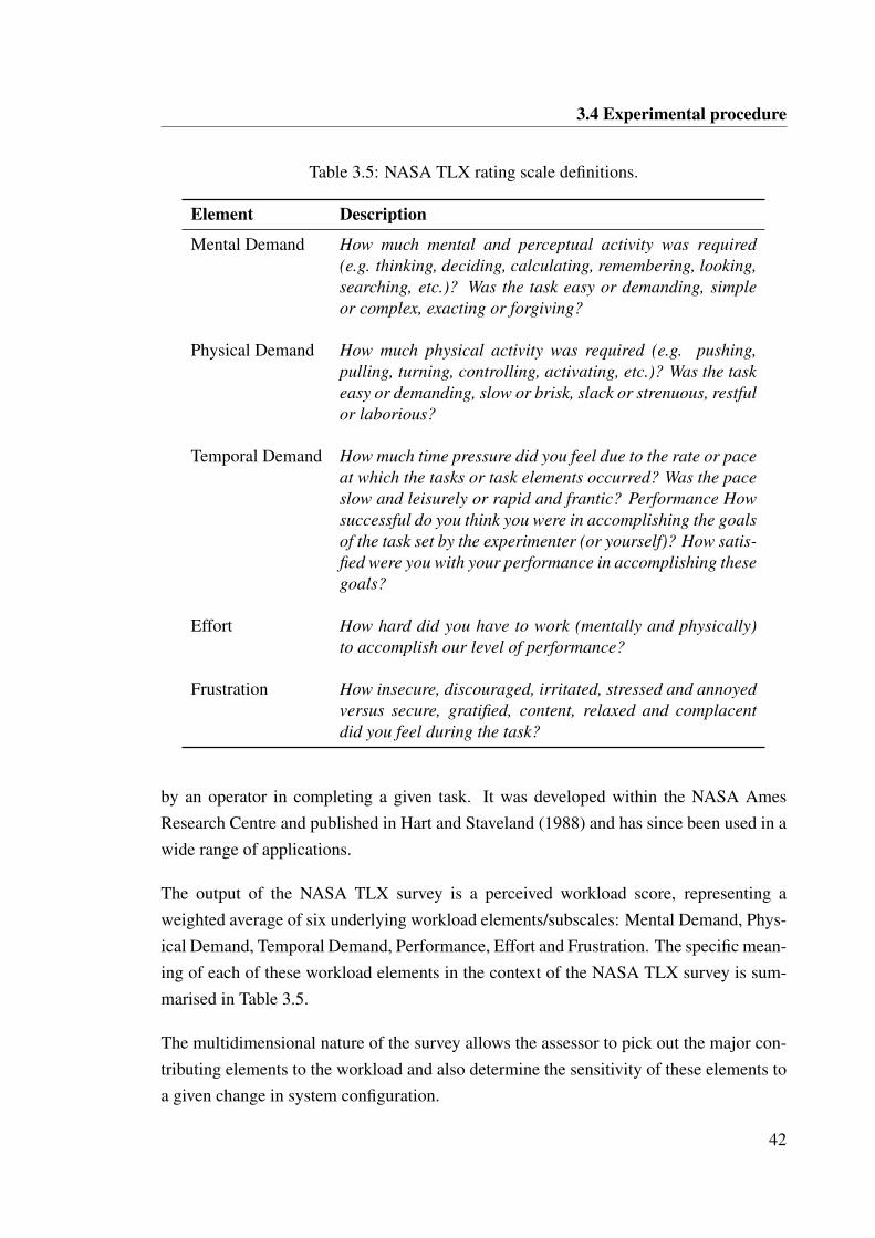
3.4 Experimental procedure
Table 3.5: NASA TLX rating scale definitions.
Element Description
Mental Demand How much mental and perceptual activity was required(e.g. thinking, deciding, calculating, remembering, looking,searching, etc.)? Was the task easy or demanding, simpleor complex, exacting or forgiving?
Physical Demand How much physical activity was required (e.g. pushing,pulling, turning, controlling, activating, etc.)? Was the taskeasy or demanding, slow or brisk, slack or strenuous, restfulor laborious?
Temporal Demand How much time pressure did you feel due to the rate or paceat which the tasks or task elements occurred? Was the paceslow and leisurely or rapid and frantic? Performance Howsuccessful do you think you were in accomplishing the goalsof the task set by the experimenter (or yourself)? How satis-fied were you with your performance in accomplishing thesegoals?
Effort How hard did you have to work (mentally and physically)to accomplish our level of performance?
Frustration How insecure, discouraged, irritated, stressed and annoyedversus secure, gratified, content, relaxed and complacentdid you feel during the task?
by an operator in completing a given task. It was developed within the NASA AmesResearch Centre and published in Hart and Staveland (1988) and has since been used in awide range of applications.
The output of the NASA TLX survey is a perceived workload score, representing aweighted average of six underlying workload elements/subscales: Mental Demand, Phys-ical Demand, Temporal Demand, Performance, Effort and Frustration. The specific mean-ing of each of these workload elements in the context of the NASA TLX survey is sum-marised in Table 3.5.
The multidimensional nature of the survey allows the assessor to pick out the major con-tributing elements to the workload and also determine the sensitivity of these elements toa given change in system configuration.
42
3.4 Experimental procedure
The NASA TLX survey is separated into two parts. Part one of the procedure involvesthe subject rating the magnitude of each element experienced within the given task on ascale from 0 to 100. Part two of the procedure involves pairwise comparison betweenthe elements, with the selected element in each pair deemed to be contributing more tothe perceived workload by the subject. For the six elements, 15 possible comparisons arequeried after which each element is assigned a weight. With the ratings and weights, theweighted average of the elements is calculated, giving the workload score. A lower scoreis indicative of a lighter perceived workload.
3.4.6 Experimental plan
The experimental plan was separated into two separate stages of data collection. Thisseparation was a consequence of site availability, staffing constraints and continuing de-velopment of the enhanced perception cell. Unavoidably, a different operator was usedas the subject in each stage. Both operators possessed extensive on board operationalexperience (>5 years) but limited line-of-sight and non-line-of-sight teleoperation expe-rience. Note that the operator familiarisation, described in 3.4.3, was completed prior toconducting experiments.
In all cases, the unaugmented conventional non-line-of-sight bulldozer teleoperation sys-tem is considered the baseline against which the effect of perception enhancements isevaluated. However, the task visualisation is applied in all instances except where indi-cated. Tests were also run with the operator performing the task on board the bulldozer toprovide a relative comparison.
The first stage focussed on motion feedback and task visualisation cues. Tests in stageone were executed by Operator A. The motion configurations examined include near-fullreplication of the motion the operator is accustomed to during on board operation, as wellas separable motion cues provided in isolation. The isolated motion cues included: pitchmotion only, vibration motion only and translational acceleration motion cues only.
The configurations where task visualisation was removed were designed to reveal howcritical the task visualisation was to operator performance and whether the provision ofmotion feedback might supplements this. The eight configurations which constitute stageone are listed in Table 3.6. The specific augmentations applied in each configuration arelisted as per Table 3.3.
43
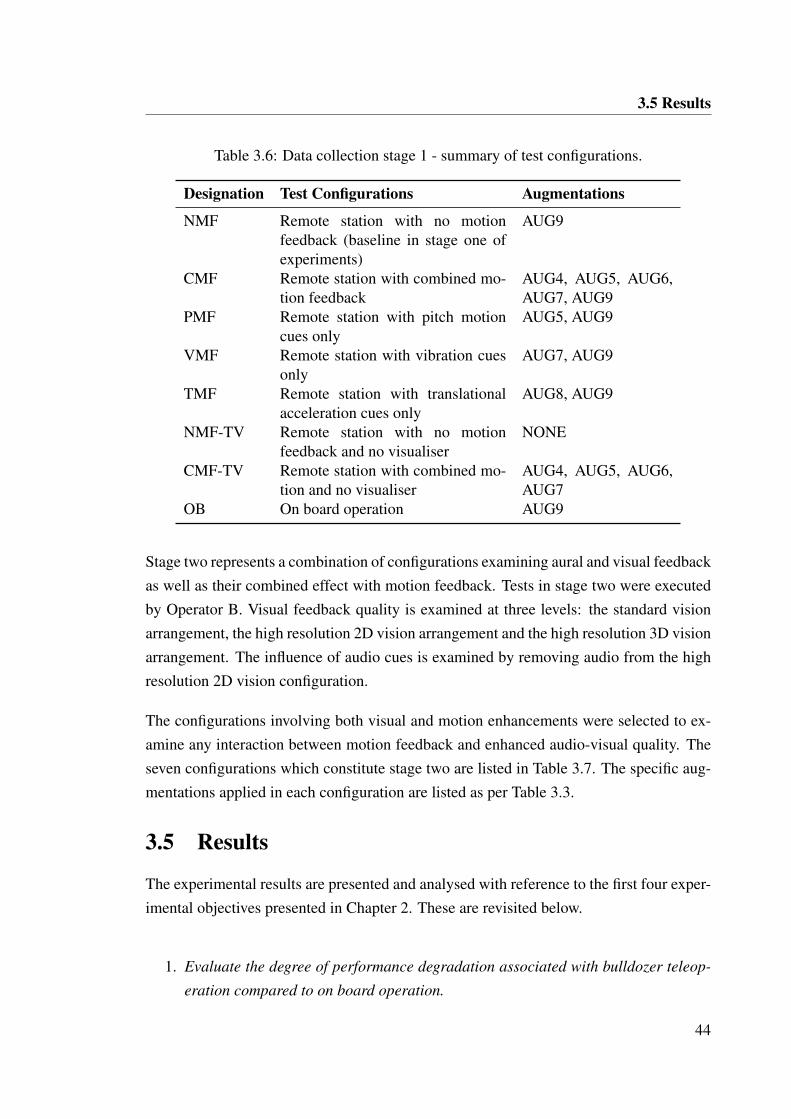
3.5 Results
Table 3.6: Data collection stage 1 - summary of test configurations.
Designation Test Configurations Augmentations
NMF Remote station with no motionfeedback (baseline in stage one ofexperiments)
AUG9
CMF Remote station with combined mo-tion feedback
AUG4, AUG5, AUG6,AUG7, AUG9
PMF Remote station with pitch motioncues only
AUG5, AUG9
VMF Remote station with vibration cuesonly
AUG7, AUG9
TMF Remote station with translationalacceleration cues only
AUG8, AUG9
NMF-TV Remote station with no motionfeedback and no visualiser
NONE
CMF-TV Remote station with combined mo-tion and no visualiser
AUG4, AUG5, AUG6,AUG7
OB On board operation AUG9
Stage two represents a combination of configurations examining aural and visual feedbackas well as their combined effect with motion feedback. Tests in stage two were executedby Operator B. Visual feedback quality is examined at three levels: the standard visionarrangement, the high resolution 2D vision arrangement and the high resolution 3D visionarrangement. The influence of audio cues is examined by removing audio from the highresolution 2D vision configuration.
The configurations involving both visual and motion enhancements were selected to ex-amine any interaction between motion feedback and enhanced audio-visual quality. Theseven configurations which constitute stage two are listed in Table 3.7. The specific aug-mentations applied in each configuration are listed as per Table 3.3.
3.5 Results
The experimental results are presented and analysed with reference to the first four exper-imental objectives presented in Chapter 2. These are revisited below.
1. Evaluate the degree of performance degradation associated with bulldozer teleop-
eration compared to on board operation.
44
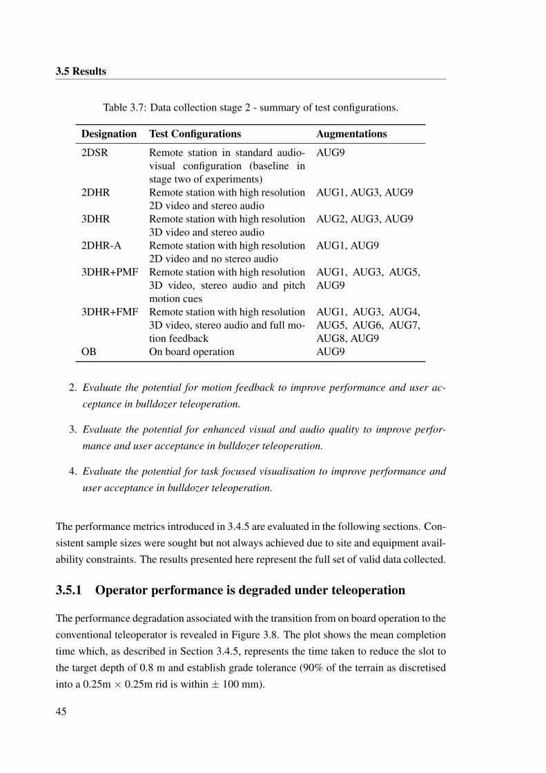
3.5 Results
Table 3.7: Data collection stage 2 - summary of test configurations.
Designation Test Configurations Augmentations
2DSR Remote station in standard audio-visual configuration (baseline instage two of experiments)
AUG9
2DHR Remote station with high resolution2D video and stereo audio
AUG1, AUG3, AUG9
3DHR Remote station with high resolution3D video and stereo audio
AUG2, AUG3, AUG9
2DHR-A Remote station with high resolution2D video and no stereo audio
AUG1, AUG9
3DHR+PMF Remote station with high resolution3D video, stereo audio and pitchmotion cues
AUG1, AUG3, AUG5,AUG9
3DHR+FMF Remote station with high resolution3D video, stereo audio and full mo-tion feedback
AUG1, AUG3, AUG4,AUG5, AUG6, AUG7,AUG8, AUG9
OB On board operation AUG9
2. Evaluate the potential for motion feedback to improve performance and user ac-
ceptance in bulldozer teleoperation.
3. Evaluate the potential for enhanced visual and audio quality to improve perfor-
mance and user acceptance in bulldozer teleoperation.
4. Evaluate the potential for task focused visualisation to improve performance and
user acceptance in bulldozer teleoperation.
The performance metrics introduced in 3.4.5 are evaluated in the following sections. Con-sistent sample sizes were sought but not always achieved due to site and equipment avail-ability constraints. The results presented here represent the full set of valid data collected.
3.5.1 Operator performance is degraded under teleoperation
The performance degradation associated with the transition from on board operation to theconventional teleoperator is revealed in Figure 3.8. The plot shows the mean completiontime which, as described in Section 3.4.5, represents the time taken to reduce the slot tothe target depth of 0.8 m and establish grade tolerance (90% of the terrain as discretisedinto a 0.25m × 0.25m rid is within ± 100 mm).
45
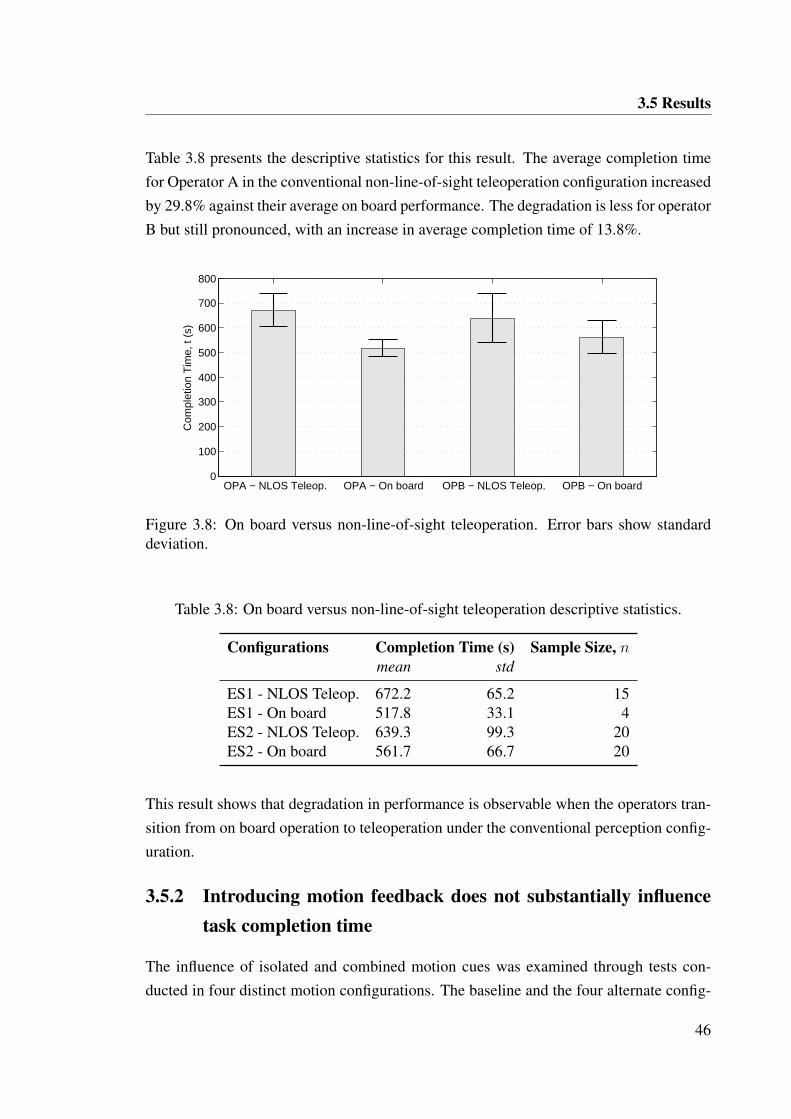
3.5 Results
Table 3.8 presents the descriptive statistics for this result. The average completion timefor Operator A in the conventional non-line-of-sight teleoperation configuration increasedby 29.8% against their average on board performance. The degradation is less for operatorB but still pronounced, with an increase in average completion time of 13.8%.
OPA − NLOS Teleop. OPA − On board OPB − NLOS Teleop. OPB − On board0
100
200
300
400
500
600
700
800
Com
plet
ion
Tim
e, t
(s)
Figure 3.8: On board versus non-line-of-sight teleoperation. Error bars show standarddeviation.
Table 3.8: On board versus non-line-of-sight teleoperation descriptive statistics.
Configurations Completion Time (s) Sample Size, nmean std
ES1 - NLOS Teleop. 672.2 65.2 15ES1 - On board 517.8 33.1 4ES2 - NLOS Teleop. 639.3 99.3 20ES2 - On board 561.7 66.7 20
This result shows that degradation in performance is observable when the operators tran-sition from on board operation to teleoperation under the conventional perception config-uration.
3.5.2 Introducing motion feedback does not substantially influencetask completion time
The influence of isolated and combined motion cues was examined through tests con-ducted in four distinct motion configurations. The baseline and the four alternate config-
46
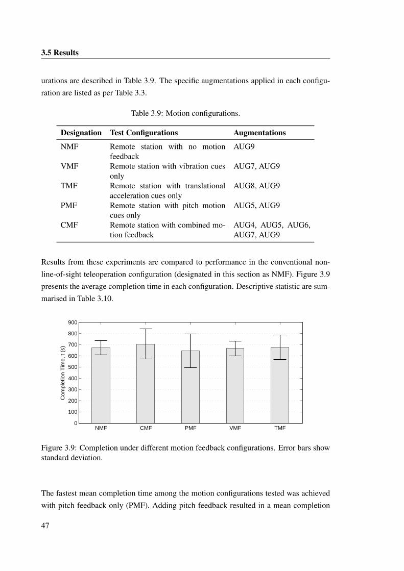
3.5 Results
urations are described in Table 3.9. The specific augmentations applied in each configu-ration are listed as per Table 3.3.
Table 3.9: Motion configurations.
Designation Test Configurations Augmentations
NMF Remote station with no motionfeedback
AUG9
VMF Remote station with vibration cuesonly
AUG7, AUG9
TMF Remote station with translationalacceleration cues only
AUG8, AUG9
PMF Remote station with pitch motioncues only
AUG5, AUG9
CMF Remote station with combined mo-tion feedback
AUG4, AUG5, AUG6,AUG7, AUG9
Results from these experiments are compared to performance in the conventional non-line-of-sight teleoperation configuration (designated in this section as NMF). Figure 3.9presents the average completion time in each configuration. Descriptive statistic are sum-marised in Table 3.10.
NMF CMF PMF VMF TMF0
100
200
300
400
500
600
700
800
900
Com
plet
ion
Tim
e, t
(s)
Figure 3.9: Completion under different motion feedback configurations. Error bars showstandard deviation.
The fastest mean completion time among the motion configurations tested was achievedwith pitch feedback only (PMF). Adding pitch feedback resulted in a mean completion
47
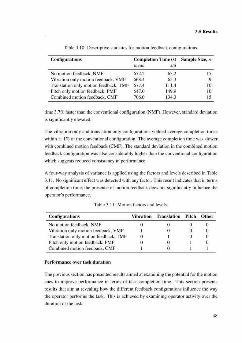
3.5 Results
Table 3.10: Descriptive statistics for motion feedback configurations.
Configurations Completion Time (s) Sample Size, nmean std
No motion feedback, NMF 672.2 65.2 15Vibration only motion feedback, VMF 668.4 65.3 9Translation only motion feedback, TMF 677.4 111.4 10Pitch only motion feedback, PMF 647.0 149.9 10Combined motion feedback, CMF 706.0 134.3 15
time 3.7% faster than the conventional configuration (NMF). However, standard deviationis significantly elevated.
The vibration only and translation only configurations yielded average completion timeswithin ± 1% of the conventional configuration. The average completion time was slowerwith combined motion feedback (CMF). The standard deviation in the combined motionfeedback configuration was also considerably higher than the conventional configurationwhich suggests reduced consistency in performance.
A four-way analysis of variance is applied using the factors and levels described in Table3.11. No significant effect was detected with any factor. This result indicates that in termsof completion time, the presence of motion feedback does not significantly influence theoperator’s performance.
Table 3.11: Motion factors and levels.
Configurations Vibration Translation Pitch Other
No motion feedback, NMF 0 0 0 0Vibration only motion feedback, VMF 1 0 0 0Translation only motion feedback, TMF 0 1 0 0Pitch only motion feedback, PMF 0 0 1 0Combined motion feedback, CMF 1 0 1 1
Performance over task duration
The previous section has presented results aimed at examining the potential for the motioncues to improve performance in terms of task completion time. This section presentsresults that aim at revealing how the different feedback configurations influence the waythe operator performs the task. This is achieved by examining operator activity over theduration of the task.
48
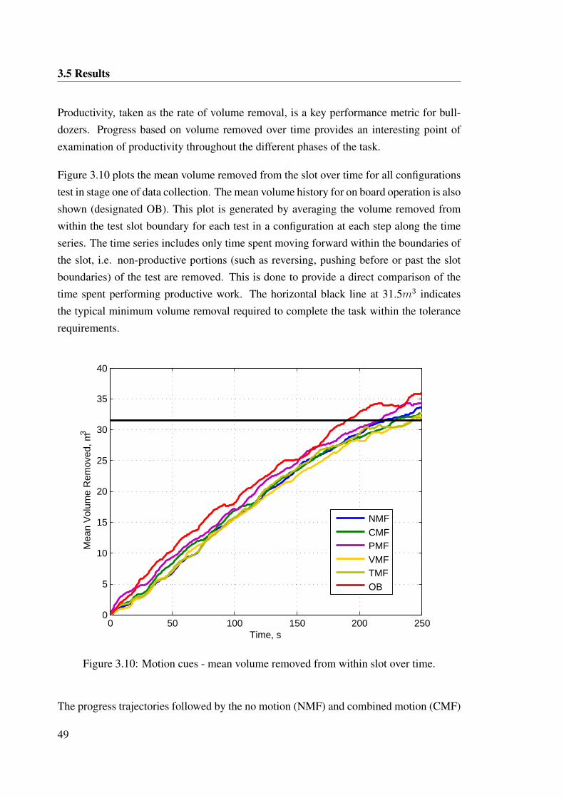
3.5 Results
Productivity, taken as the rate of volume removal, is a key performance metric for bull-dozers. Progress based on volume removed over time provides an interesting point ofexamination of productivity throughout the different phases of the task.
Figure 3.10 plots the mean volume removed from the slot over time for all configurationstest in stage one of data collection. The mean volume history for on board operation is alsoshown (designated OB). This plot is generated by averaging the volume removed fromwithin the test slot boundary for each test in a configuration at each step along the timeseries. The time series includes only time spent moving forward within the boundaries ofthe slot, i.e. non-productive portions (such as reversing, pushing before or past the slotboundaries) of the test are removed. This is done to provide a direct comparison of thetime spent performing productive work. The horizontal black line at 31.5m3 indicatesthe typical minimum volume removal required to complete the task within the tolerancerequirements.
0 50 100 150 200 2500
5
10
15
20
25
30
35
40
Time, s
Mea
n V
olum
e R
emov
ed, m
3
NMFCMFPMFVMFTMFOB
Figure 3.10: Motion cues - mean volume removed from within slot over time.
The progress trajectories followed by the no motion (NMF) and combined motion (CMF)
49
3.5 Results
configurations show little difference. The rate of volume removal appears consistent forboth configurations. This is consistent with the minimal difference observed in task com-pletion time for these two configurations.
The vibration motion configuration (VMF) and the translational acceleration / deceler-ation cue configuration (TMF) display a similar trajectory to the default configuration(NMF) up until approximately 120s. At this point, the vibration motion configurationslows in volume removal terms while the translational acceleration / deceleration cueconfiguration (TMF) continues to closely match the static configuration (NMF). Thepitch only configuration (PMF), however, leads all other configurations in volume re-moval terms throughout the duration of the time series shown. This appears to indicateon average higher productivity as represented by rate of volume removal.
The progress trajectory observed in on board operation (OB) leads all teleoperation con-figurations throughout the time series as might be expected. The isolated pitch motionfeedback (PMF) configuration provides a trajectory that falls roughly between the con-ventional non-line-of-sight teleoperation configuration (NMF) and on board operation(OB).
An alternative representation of Figure 3.10 is provided by Figure 3.11. The slot bull-dozing task is broken down into three phases based on volume: 0-10m3, 10-20m3 and20-30m3. Figure 3.11 shows the average time taken to complete each volume phase.
Figure 3.11a shows that the combined motion (CMF) and the isolated pitch motion (PMF)configuration complete the first phase marginally faster than the conventional non-line-of-sight teleoperation configuration (NMF). There is limited distinction observable in thelatter two phases of the task.
The above results appear to indicate some distinction in performance between the earlystage and later stage of the task. Figure 3.12a presents the mean volume per push overpushes 1 to 5 in the tests. Figure 3.12b presents the mean volume per push for the remain-der of the test.
In Figure 3.12a, the mean volume per push is distinctly elevated in the pitch motion con-figuration (PMF) compared with the conventional non-line-of-sight configuration (NMF).The average volume per push in the first five pushes is 19.6% higher in the pitch motionconfiguration (PMF) than in the conventional configuration. This compares with 14.6%
50
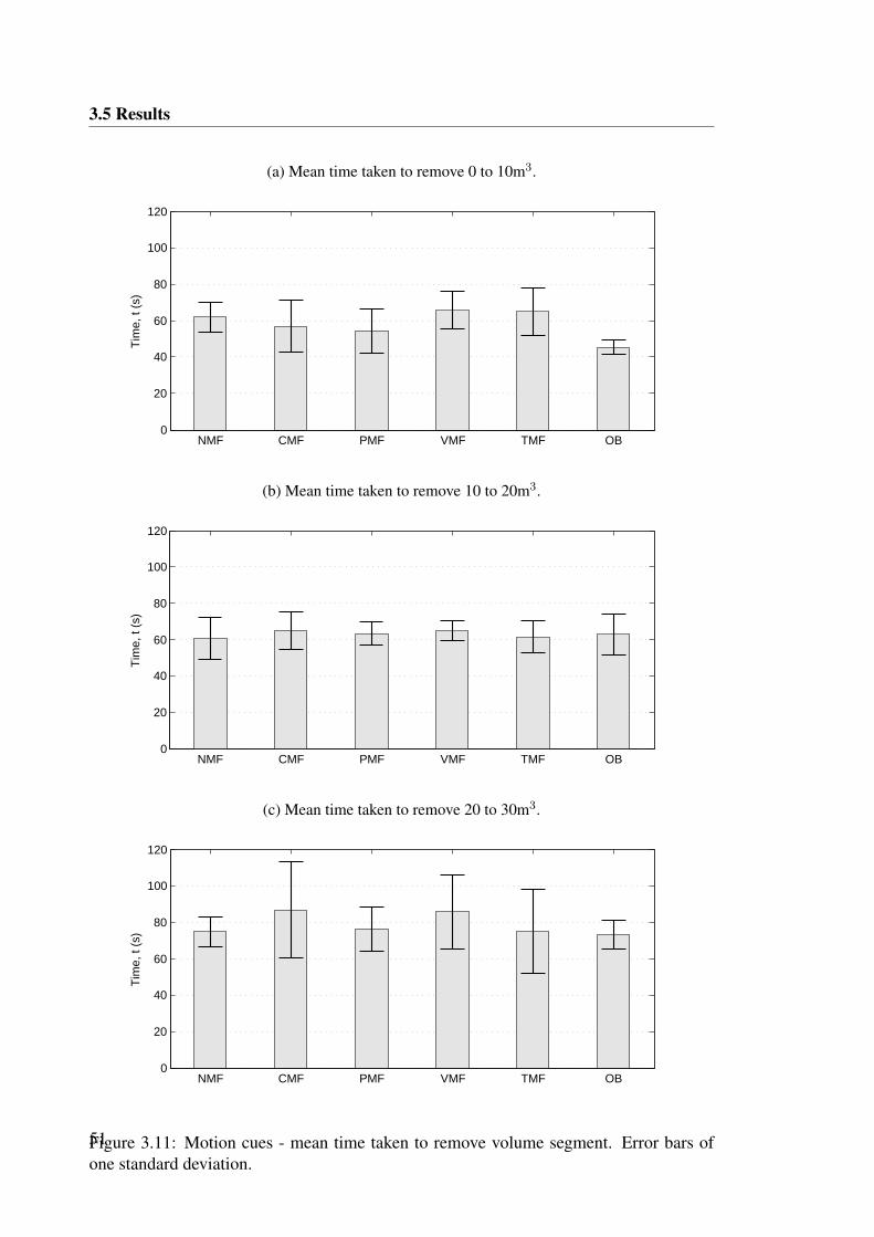
3.5 Results
(a) Mean time taken to remove 0 to 10m3.
NMF CMF PMF VMF TMF OB0
20
40
60
80
100
120
Tim
e, t
(s)
(b) Mean time taken to remove 10 to 20m3.
NMF CMF PMF VMF TMF OB0
20
40
60
80
100
120
Tim
e, t
(s)
(c) Mean time taken to remove 20 to 30m3.
NMF CMF PMF VMF TMF OB0
20
40
60
80
100
120
Tim
e, t
(s)
Figure 3.11: Motion cues - mean time taken to remove volume segment. Error bars ofone standard deviation.51
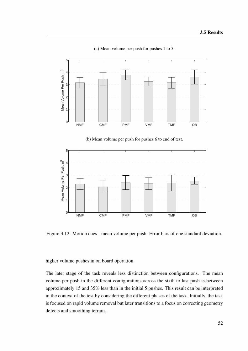
3.5 Results
(a) Mean volume per push for pushes 1 to 5.
NMF CMF PMF VMF TMF OB0
1
2
3
4
5M
ean
Vol
ume
Per
Pus
h, m
3
(b) Mean volume per push for pushes 6 to end of test.
NMF CMF PMF VMF TMF OB0
1
2
3
4
5
Mea
n V
olum
e P
er P
ush,
m3
Figure 3.12: Motion cues - mean volume per push. Error bars of one standard deviation.
higher volume pushes in on board operation.
The later stage of the task reveals less distinction between configurations. The meanvolume per push in the different configurations across the sixth to last push is betweenapproximately 15 and 35% less than in the initial 5 pushes. This result can be interpretedin the context of the test by considering the different phases of the task. Initially, the taskis focused on rapid volume removal but later transitions to a focus on correcting geometrydefects and smoothing terrain.
52
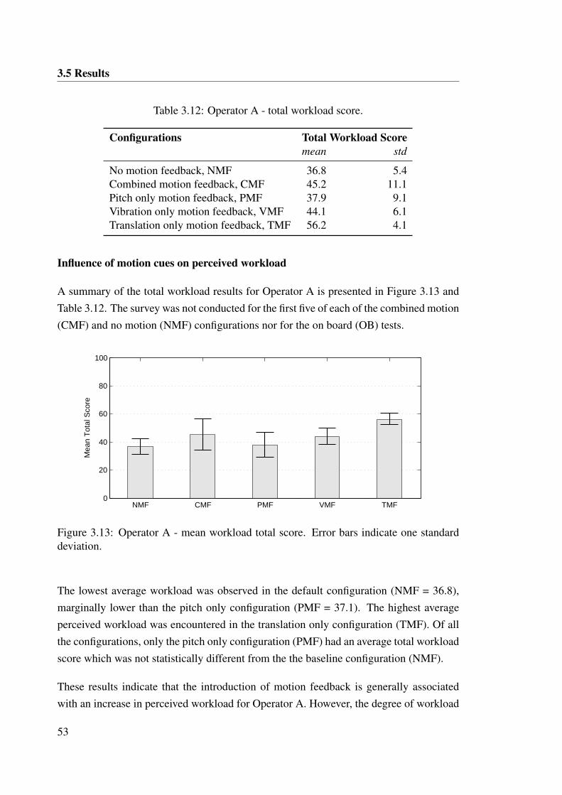
3.5 Results
Table 3.12: Operator A - total workload score.
Configurations Total Workload Scoremean std
No motion feedback, NMF 36.8 5.4Combined motion feedback, CMF 45.2 11.1Pitch only motion feedback, PMF 37.9 9.1Vibration only motion feedback, VMF 44.1 6.1Translation only motion feedback, TMF 56.2 4.1
Influence of motion cues on perceived workload
A summary of the total workload results for Operator A is presented in Figure 3.13 andTable 3.12. The survey was not conducted for the first five of each of the combined motion(CMF) and no motion (NMF) configurations nor for the on board (OB) tests.
NMF CMF PMF VMF TMF0
20
40
60
80
100
Mea
n T
otal
Sco
re
Figure 3.13: Operator A - mean workload total score. Error bars indicate one standarddeviation.
The lowest average workload was observed in the default configuration (NMF = 36.8),marginally lower than the pitch only configuration (PMF = 37.1). The highest averageperceived workload was encountered in the translation only configuration (TMF). Of allthe configurations, only the pitch only configuration (PMF) had an average total workloadscore which was not statistically different from the the baseline configuration (NMF).
These results indicate that the introduction of motion feedback is generally associatedwith an increase in perceived workload for Operator A. However, the degree of workload
53
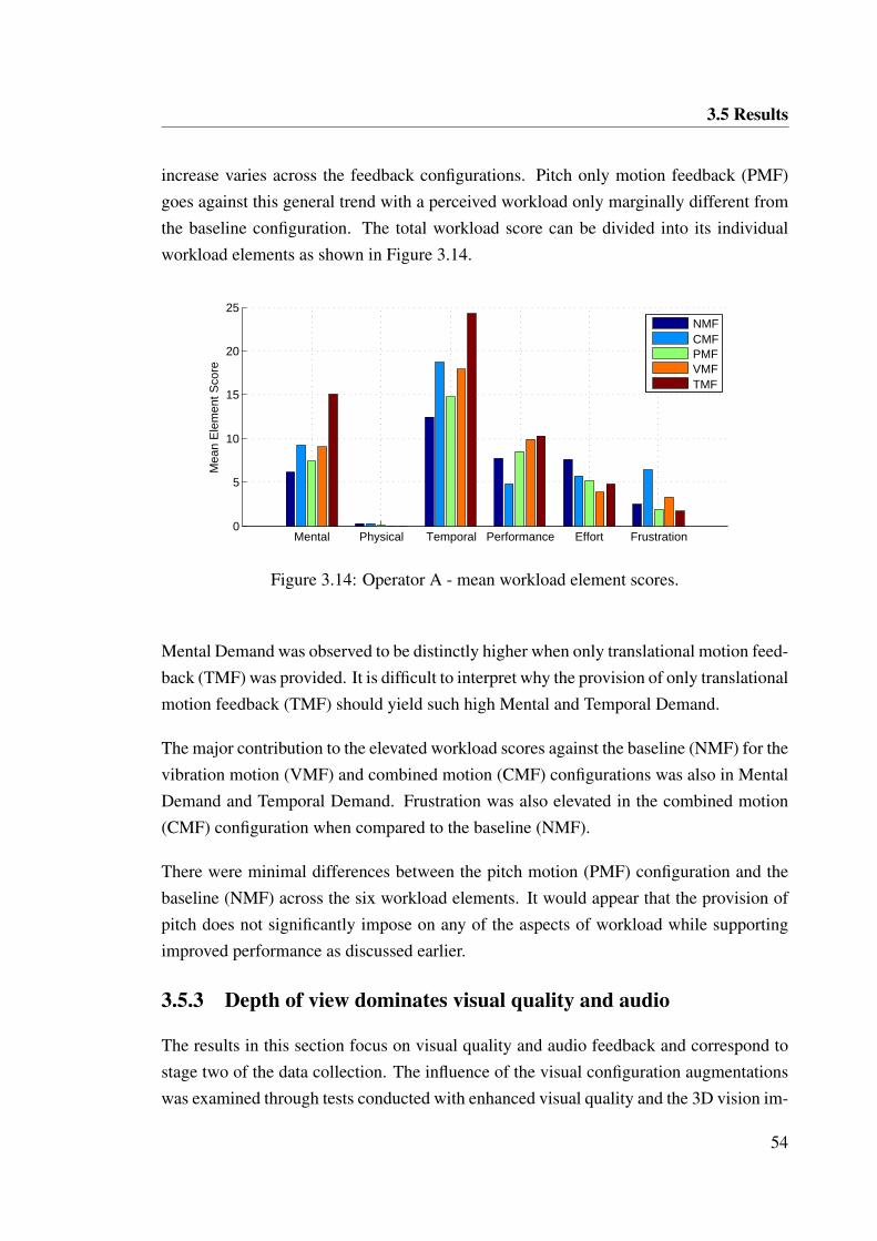
3.5 Results
increase varies across the feedback configurations. Pitch only motion feedback (PMF)goes against this general trend with a perceived workload only marginally different fromthe baseline configuration. The total workload score can be divided into its individualworkload elements as shown in Figure 3.14.
Mental Physical Temporal Performance Effort Frustration0
5
10
15
20
25
Mea
n E
lem
ent S
core
NMFCMFPMFVMFTMF
Figure 3.14: Operator A - mean workload element scores.
Mental Demand was observed to be distinctly higher when only translational motion feed-back (TMF) was provided. It is difficult to interpret why the provision of only translationalmotion feedback (TMF) should yield such high Mental and Temporal Demand.
The major contribution to the elevated workload scores against the baseline (NMF) for thevibration motion (VMF) and combined motion (CMF) configurations was also in MentalDemand and Temporal Demand. Frustration was also elevated in the combined motion(CMF) configuration when compared to the baseline (NMF).
There were minimal differences between the pitch motion (PMF) configuration and thebaseline (NMF) across the six workload elements. It would appear that the provision ofpitch does not significantly impose on any of the aspects of workload while supportingimproved performance as discussed earlier.
3.5.3 Depth of view dominates visual quality and audio
The results in this section focus on visual quality and audio feedback and correspond tostage two of the data collection. The influence of the visual configuration augmentationswas examined through tests conducted with enhanced visual quality and the 3D vision im-
54
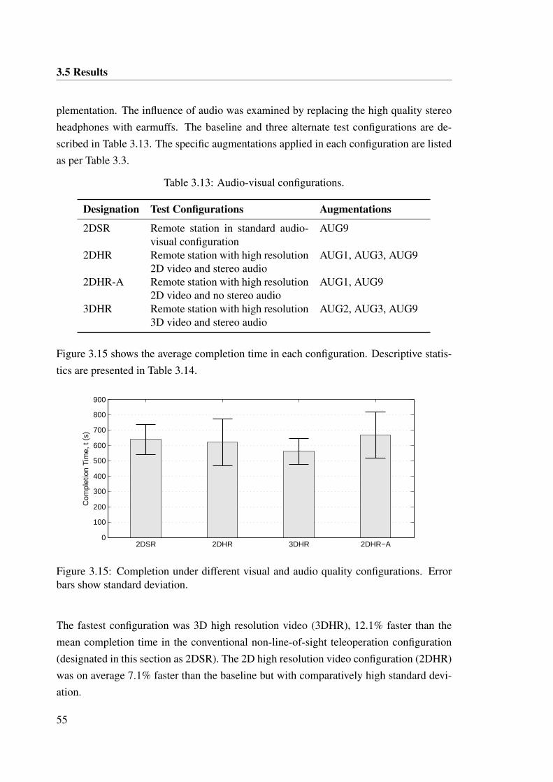
3.5 Results
plementation. The influence of audio was examined by replacing the high quality stereoheadphones with earmuffs. The baseline and three alternate test configurations are de-scribed in Table 3.13. The specific augmentations applied in each configuration are listedas per Table 3.3.
Table 3.13: Audio-visual configurations.
Designation Test Configurations Augmentations
2DSR Remote station in standard audio-visual configuration
AUG9
2DHR Remote station with high resolution2D video and stereo audio
AUG1, AUG3, AUG9
2DHR-A Remote station with high resolution2D video and no stereo audio
AUG1, AUG9
3DHR Remote station with high resolution3D video and stereo audio
AUG2, AUG3, AUG9
Figure 3.15 shows the average completion time in each configuration. Descriptive statis-tics are presented in Table 3.14.
2DSR 2DHR 3DHR 2DHR−A0
100
200
300
400
500
600
700
800
900
Com
plet
ion
Tim
e, t
(s)
Figure 3.15: Completion under different visual and audio quality configurations. Errorbars show standard deviation.
The fastest configuration was 3D high resolution video (3DHR), 12.1% faster than themean completion time in the conventional non-line-of-sight teleoperation configuration(designated in this section as 2DSR). The 2D high resolution video configuration (2DHR)was on average 7.1% faster than the baseline but with comparatively high standard devi-ation.
55
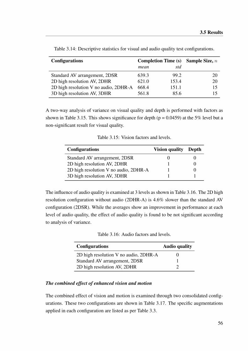
3.5 Results
Table 3.14: Descriptive statistics for visual and audio quality test configurations.
Configurations Completion Time (s) Sample Size, nmean std
Standard AV arrangement, 2DSR 639.3 99.2 202D high resolution AV, 2DHR 621.0 153.4 202D high resolution V no audio, 2DHR-A 668.4 151.1 153D high resolution AV, 3DHR 561.8 85.6 15
A two-way analysis of variance on visual quality and depth is performed with factors asshown in Table 3.15. This shows significance for depth (p = 0.0459) at the 5% level but anon-significant result for visual quality.
Table 3.15: Vision factors and levels.
Configurations Vision quality Depth
Standard AV arrangement, 2DSR 0 02D high resolution AV, 2DHR 1 02D high resolution V no audio, 2DHR-A 1 03D high resolution AV, 3DHR 1 1
The influence of audio quality is examined at 3 levels as shown in Table 3.16. The 2D highresolution configuration without audio (2DHR-A) is 4.6% slower than the standard AVconfiguration (2DSR). While the averages show an improvement in performance at eachlevel of audio quality, the effect of audio quality is found to be not significant accordingto analysis of variance.
Table 3.16: Audio factors and levels.
Configurations Audio quality
2D high resolution V no audio, 2DHR-A 0Standard AV arrangement, 2DSR 12D high resolution AV, 2DHR 2
The combined effect of enhanced vision and motion
The combined effect of vision and motion is examined through two consolidated config-urations. These two configurations are shown in Table 3.17. The specific augmentationsapplied in each configuration are listed as per Table 3.3.
56
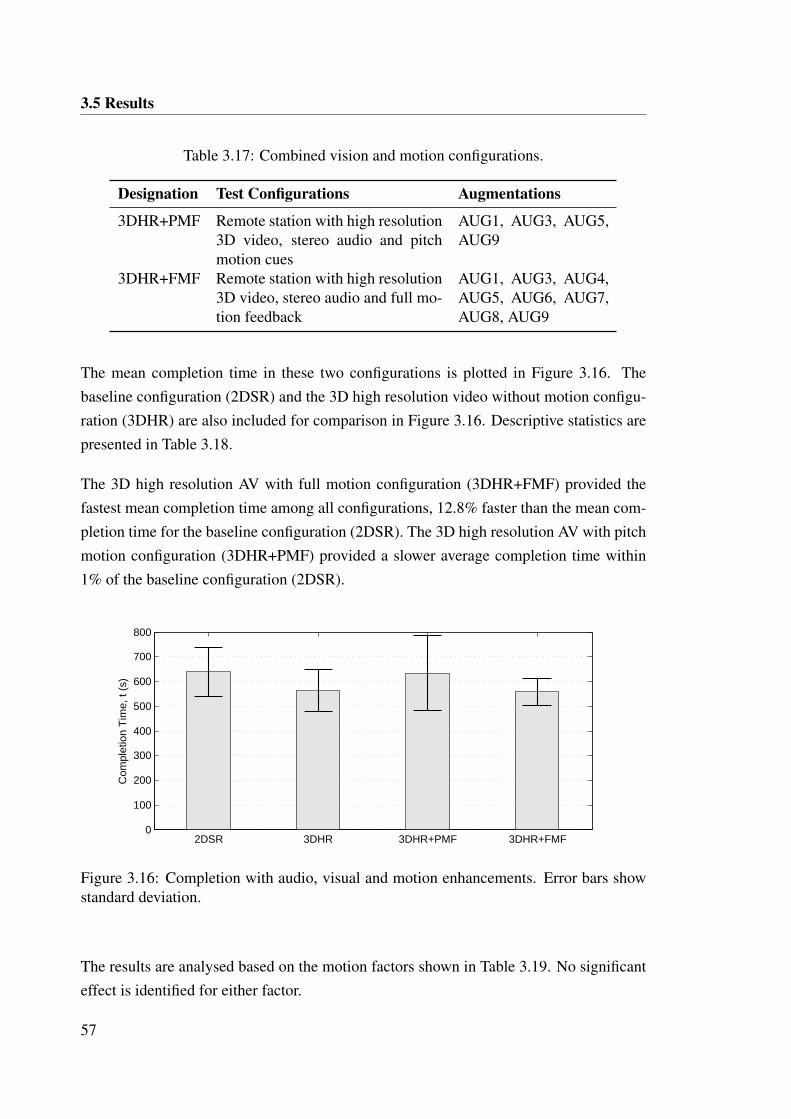
3.5 Results
Table 3.17: Combined vision and motion configurations.
Designation Test Configurations Augmentations
3DHR+PMF Remote station with high resolution3D video, stereo audio and pitchmotion cues
AUG1, AUG3, AUG5,AUG9
3DHR+FMF Remote station with high resolution3D video, stereo audio and full mo-tion feedback
AUG1, AUG3, AUG4,AUG5, AUG6, AUG7,AUG8, AUG9
The mean completion time in these two configurations is plotted in Figure 3.16. Thebaseline configuration (2DSR) and the 3D high resolution video without motion configu-ration (3DHR) are also included for comparison in Figure 3.16. Descriptive statistics arepresented in Table 3.18.
The 3D high resolution AV with full motion configuration (3DHR+FMF) provided thefastest mean completion time among all configurations, 12.8% faster than the mean com-pletion time for the baseline configuration (2DSR). The 3D high resolution AV with pitchmotion configuration (3DHR+PMF) provided a slower average completion time within1% of the baseline configuration (2DSR).
2DSR 3DHR 3DHR+PMF 3DHR+FMF0
100
200
300
400
500
600
700
800
Com
plet
ion
Tim
e, t
(s)
Figure 3.16: Completion with audio, visual and motion enhancements. Error bars showstandard deviation.
The results are analysed based on the motion factors shown in Table 3.19. No significanteffect is identified for either factor.
57
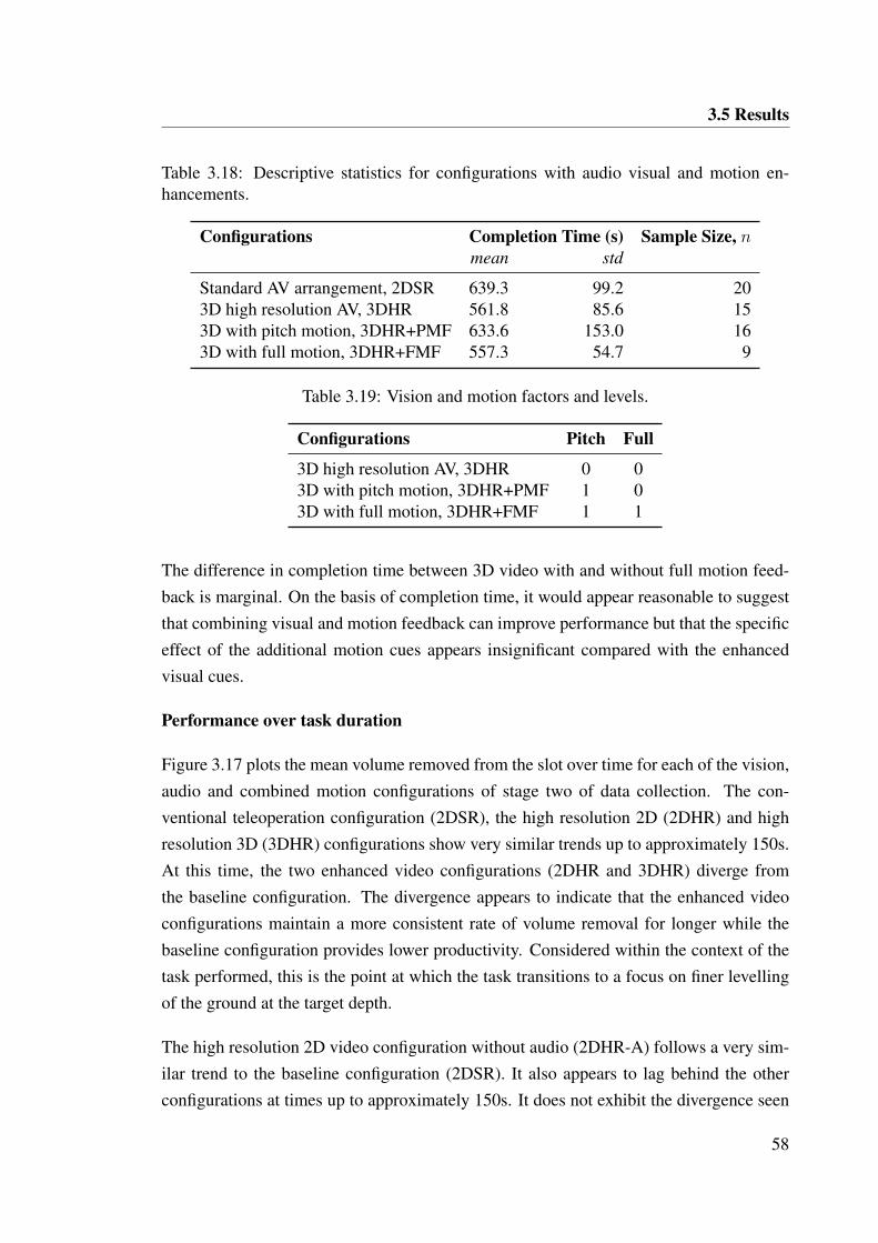
3.5 Results
Table 3.18: Descriptive statistics for configurations with audio visual and motion en-hancements.
Configurations Completion Time (s) Sample Size, nmean std
Standard AV arrangement, 2DSR 639.3 99.2 203D high resolution AV, 3DHR 561.8 85.6 153D with pitch motion, 3DHR+PMF 633.6 153.0 163D with full motion, 3DHR+FMF 557.3 54.7 9
Table 3.19: Vision and motion factors and levels.
Configurations Pitch Full
3D high resolution AV, 3DHR 0 03D with pitch motion, 3DHR+PMF 1 03D with full motion, 3DHR+FMF 1 1
The difference in completion time between 3D video with and without full motion feed-back is marginal. On the basis of completion time, it would appear reasonable to suggestthat combining visual and motion feedback can improve performance but that the specificeffect of the additional motion cues appears insignificant compared with the enhancedvisual cues.
Performance over task duration
Figure 3.17 plots the mean volume removed from the slot over time for each of the vision,audio and combined motion configurations of stage two of data collection. The con-ventional teleoperation configuration (2DSR), the high resolution 2D (2DHR) and highresolution 3D (3DHR) configurations show very similar trends up to approximately 150s.At this time, the two enhanced video configurations (2DHR and 3DHR) diverge fromthe baseline configuration. The divergence appears to indicate that the enhanced videoconfigurations maintain a more consistent rate of volume removal for longer while thebaseline configuration provides lower productivity. Considered within the context of thetask performed, this is the point at which the task transitions to a focus on finer levellingof the ground at the target depth.
The high resolution 2D video configuration without audio (2DHR-A) follows a very sim-ilar trend to the baseline configuration (2DSR). It also appears to lag behind the otherconfigurations at times up to approximately 150s. It does not exhibit the divergence seen
58
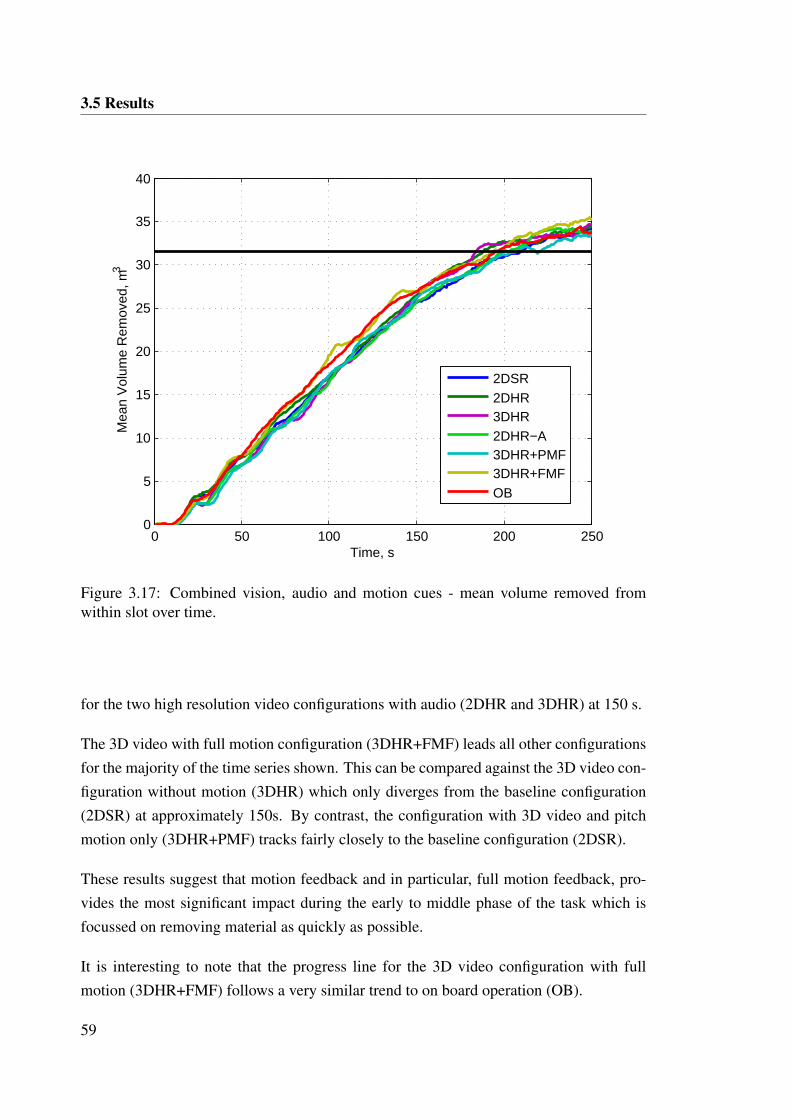
3.5 Results
0 50 100 150 200 2500
5
10
15
20
25
30
35
40
Time, s
Mea
n V
olum
e R
emov
ed, m
3
2DSR2DHR3DHR2DHR−A3DHR+PMF3DHR+FMFOB
Figure 3.17: Combined vision, audio and motion cues - mean volume removed fromwithin slot over time.
for the two high resolution video configurations with audio (2DHR and 3DHR) at 150 s.
The 3D video with full motion configuration (3DHR+FMF) leads all other configurationsfor the majority of the time series shown. This can be compared against the 3D video con-figuration without motion (3DHR) which only diverges from the baseline configuration(2DSR) at approximately 150s. By contrast, the configuration with 3D video and pitchmotion only (3DHR+PMF) tracks fairly closely to the baseline configuration (2DSR).
These results suggest that motion feedback and in particular, full motion feedback, pro-vides the most significant impact during the early to middle phase of the task which isfocussed on removing material as quickly as possible.
It is interesting to note that the progress line for the 3D video configuration with fullmotion (3DHR+FMF) follows a very similar trend to on board operation (OB).
59
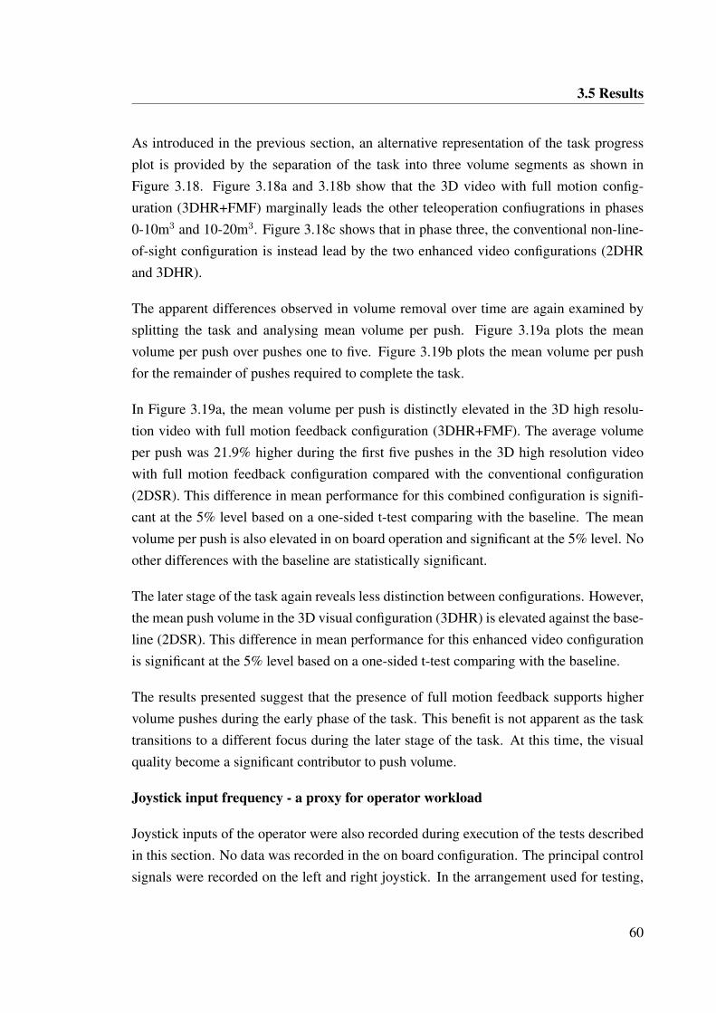
3.5 Results
As introduced in the previous section, an alternative representation of the task progressplot is provided by the separation of the task into three volume segments as shown inFigure 3.18. Figure 3.18a and 3.18b show that the 3D video with full motion config-uration (3DHR+FMF) marginally leads the other teleoperation confiugrations in phases0-10m3 and 10-20m3. Figure 3.18c shows that in phase three, the conventional non-line-of-sight configuration is instead lead by the two enhanced video configurations (2DHRand 3DHR).
The apparent differences observed in volume removal over time are again examined bysplitting the task and analysing mean volume per push. Figure 3.19a plots the meanvolume per push over pushes one to five. Figure 3.19b plots the mean volume per pushfor the remainder of pushes required to complete the task.
In Figure 3.19a, the mean volume per push is distinctly elevated in the 3D high resolu-tion video with full motion feedback configuration (3DHR+FMF). The average volumeper push was 21.9% higher during the first five pushes in the 3D high resolution videowith full motion feedback configuration compared with the conventional configuration(2DSR). This difference in mean performance for this combined configuration is signifi-cant at the 5% level based on a one-sided t-test comparing with the baseline. The meanvolume per push is also elevated in on board operation and significant at the 5% level. Noother differences with the baseline are statistically significant.
The later stage of the task again reveals less distinction between configurations. However,the mean push volume in the 3D visual configuration (3DHR) is elevated against the base-line (2DSR). This difference in mean performance for this enhanced video configurationis significant at the 5% level based on a one-sided t-test comparing with the baseline.
The results presented suggest that the presence of full motion feedback supports highervolume pushes during the early phase of the task. This benefit is not apparent as the tasktransitions to a different focus during the later stage of the task. At this time, the visualquality become a significant contributor to push volume.
Joystick input frequency - a proxy for operator workload
Joystick inputs of the operator were also recorded during execution of the tests describedin this section. No data was recorded in the on board configuration. The principal controlsignals were recorded on the left and right joystick. In the arrangement used for testing,
60
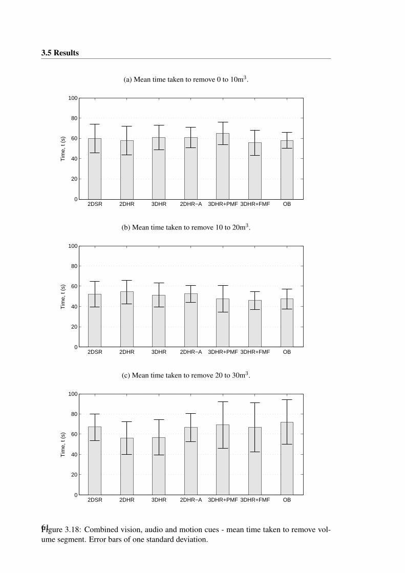
3.5 Results
(a) Mean time taken to remove 0 to 10m3.
2DSR 2DHR 3DHR 2DHR−A 3DHR+PMF 3DHR+FMF OB0
20
40
60
80
100
Tim
e, t
(s)
(b) Mean time taken to remove 10 to 20m3.
2DSR 2DHR 3DHR 2DHR−A 3DHR+PMF 3DHR+FMF OB0
20
40
60
80
100
Tim
e, t
(s)
(c) Mean time taken to remove 20 to 30m3.
2DSR 2DHR 3DHR 2DHR−A 3DHR+PMF 3DHR+FMF OB0
20
40
60
80
100
Tim
e, t
(s)
Figure 3.18: Combined vision, audio and motion cues - mean time taken to remove vol-ume segment. Error bars of one standard deviation.61
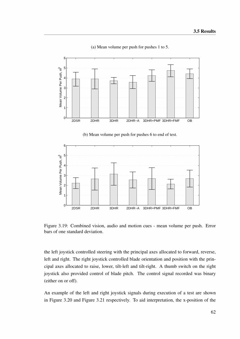
3.5 Results
(a) Mean volume per push for pushes 1 to 5.
2DSR 2DHR 3DHR 2DHR−A 3DHR+PMF 3DHR+FMF OB0
1
2
3
4
5
6M
ean
Vol
ume
Per
Pus
h, m
3
(b) Mean volume per push for pushes 6 to end of test.
2DSR 2DHR 3DHR 2DHR−A 3DHR+PMF 3DHR+FMF OB0
1
2
3
4
5
6
Mea
n V
olum
e P
er P
ush,
m3
Figure 3.19: Combined vision, audio and motion cues - mean volume per push. Errorbars of one standard deviation.
the left joystick controlled steering with the principal axes allocated to forward, reverse,left and right. The right joystick controlled blade orientation and position with the prin-cipal axes allocated to raise, lower, tilt-left and tilt-right. A thumb switch on the rightjoystick also provided control of blade pitch. The control signal recorded was binary(either on or off).
An example of the left and right joystick signals during execution of a test are shownin Figure 3.20 and Figure 3.21 respectively. To aid interpretation, the x-position of the
62
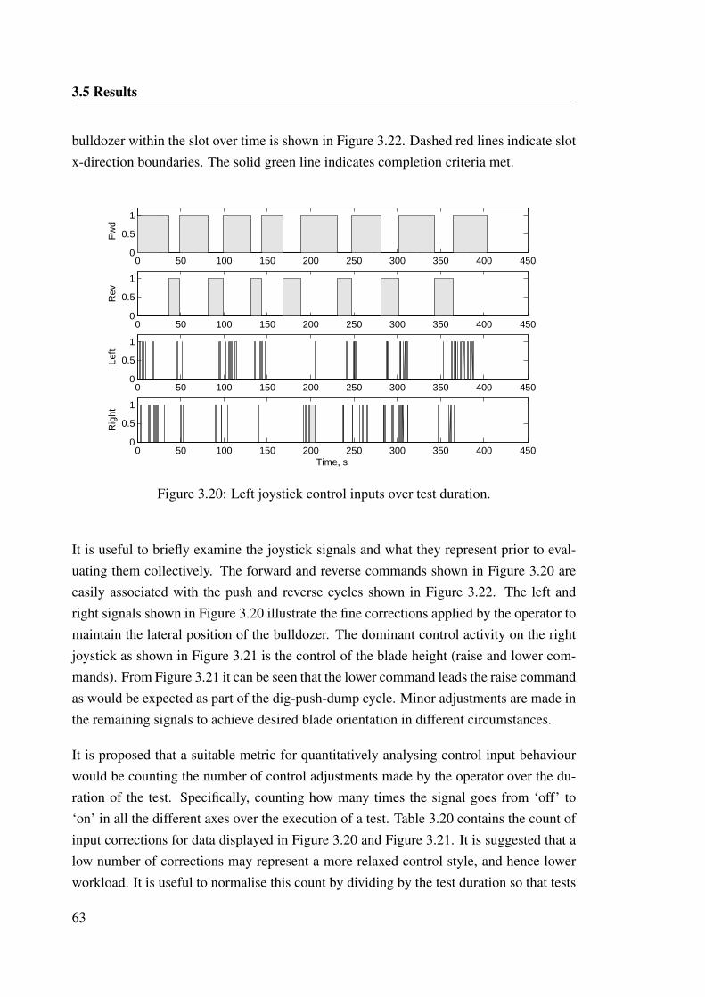
3.5 Results
bulldozer within the slot over time is shown in Figure 3.22. Dashed red lines indicate slotx-direction boundaries. The solid green line indicates completion criteria met.
0 50 100 150 200 250 300 350 400 4500
0.5
1
Fw
d
0 50 100 150 200 250 300 350 400 4500
0.5
1
Rev
0 50 100 150 200 250 300 350 400 4500
0.5
1
Left
0 50 100 150 200 250 300 350 400 4500
0.5
1
Rig
ht
Time, s
Figure 3.20: Left joystick control inputs over test duration.
It is useful to briefly examine the joystick signals and what they represent prior to eval-uating them collectively. The forward and reverse commands shown in Figure 3.20 areeasily associated with the push and reverse cycles shown in Figure 3.22. The left andright signals shown in Figure 3.20 illustrate the fine corrections applied by the operator tomaintain the lateral position of the bulldozer. The dominant control activity on the rightjoystick as shown in Figure 3.21 is the control of the blade height (raise and lower com-mands). From Figure 3.21 it can be seen that the lower command leads the raise commandas would be expected as part of the dig-push-dump cycle. Minor adjustments are made inthe remaining signals to achieve desired blade orientation in different circumstances.
It is proposed that a suitable metric for quantitatively analysing control input behaviourwould be counting the number of control adjustments made by the operator over the du-ration of the test. Specifically, counting how many times the signal goes from ‘off’ to‘on’ in all the different axes over the execution of a test. Table 3.20 contains the count ofinput corrections for data displayed in Figure 3.20 and Figure 3.21. It is suggested that alow number of corrections may represent a more relaxed control style, and hence lowerworkload. It is useful to normalise this count by dividing by the test duration so that tests
63
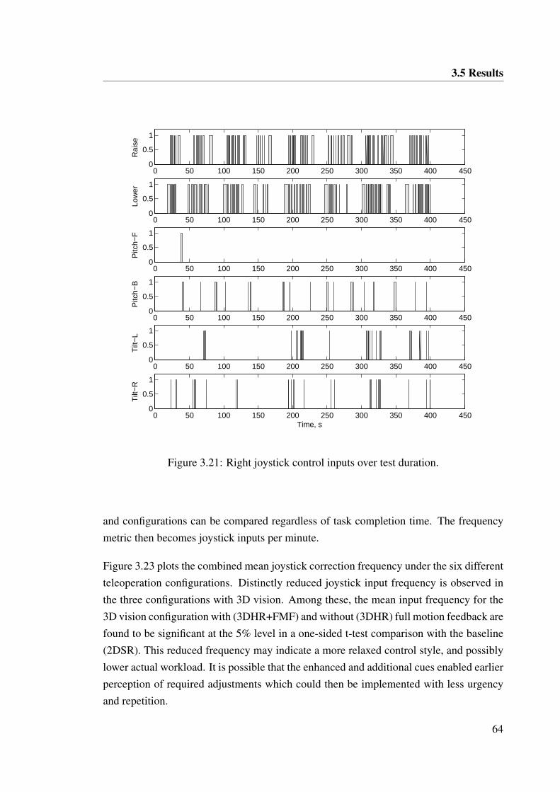
3.5 Results
0 50 100 150 200 250 300 350 400 4500
0.5
1R
aise
0 50 100 150 200 250 300 350 400 4500
0.5
1
Low
er
0 50 100 150 200 250 300 350 400 4500
0.5
1
Pitc
h−F
0 50 100 150 200 250 300 350 400 4500
0.5
1
Pitc
h−B
0 50 100 150 200 250 300 350 400 4500
0.5
1
Tilt
−L
0 50 100 150 200 250 300 350 400 4500
0.5
1
Time, s
Tilt
−R
Figure 3.21: Right joystick control inputs over test duration.
and configurations can be compared regardless of task completion time. The frequencymetric then becomes joystick inputs per minute.
Figure 3.23 plots the combined mean joystick correction frequency under the six differentteleoperation configurations. Distinctly reduced joystick input frequency is observed inthe three configurations with 3D vision. Among these, the mean input frequency for the3D vision configuration with (3DHR+FMF) and without (3DHR) full motion feedback arefound to be significant at the 5% level in a one-sided t-test comparison with the baseline(2DSR). This reduced frequency may indicate a more relaxed control style, and possiblylower actual workload. It is possible that the enhanced and additional cues enabled earlierperception of required adjustments which could then be implemented with less urgencyand repetition.
64
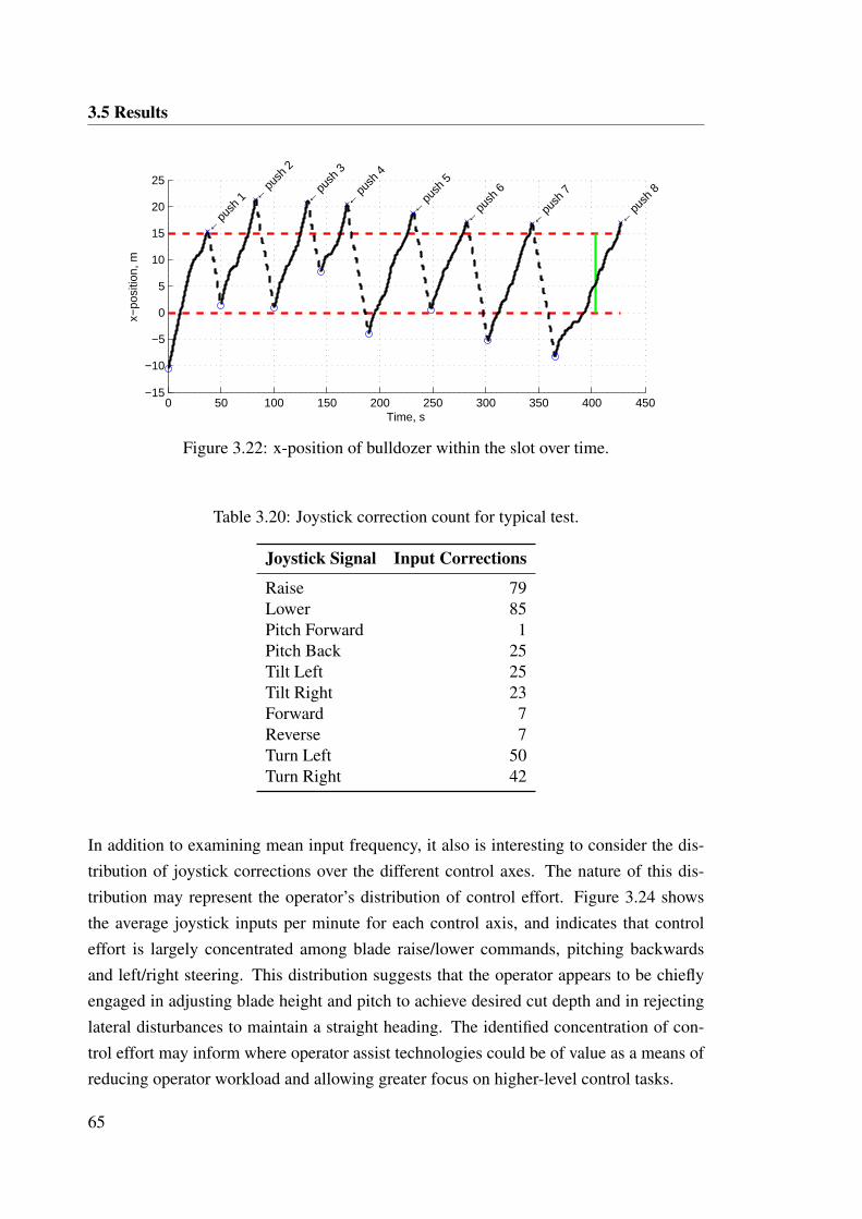
3.5 Results
0 50 100 150 200 250 300 350 400 450−15
−10
−5
0
5
10
15
20
25
← p
ush
1 ← p
ush
2
← p
ush
3
← p
ush
4
← p
ush
5
← p
ush
6
← p
ush
7
← p
ush
8
Time, s
x−po
sitio
n, m
Figure 3.22: x-position of bulldozer within the slot over time.
Table 3.20: Joystick correction count for typical test.
Joystick Signal Input Corrections
Raise 79Lower 85Pitch Forward 1Pitch Back 25Tilt Left 25Tilt Right 23Forward 7Reverse 7Turn Left 50Turn Right 42
In addition to examining mean input frequency, it also is interesting to consider the dis-tribution of joystick corrections over the different control axes. The nature of this dis-tribution may represent the operator’s distribution of control effort. Figure 3.24 showsthe average joystick inputs per minute for each control axis, and indicates that controleffort is largely concentrated among blade raise/lower commands, pitching backwardsand left/right steering. This distribution suggests that the operator appears to be chieflyengaged in adjusting blade height and pitch to achieve desired cut depth and in rejectinglateral disturbances to maintain a straight heading. The identified concentration of con-trol effort may inform where operator assist technologies could be of value as a means ofreducing operator workload and allowing greater focus on higher-level control tasks.
65
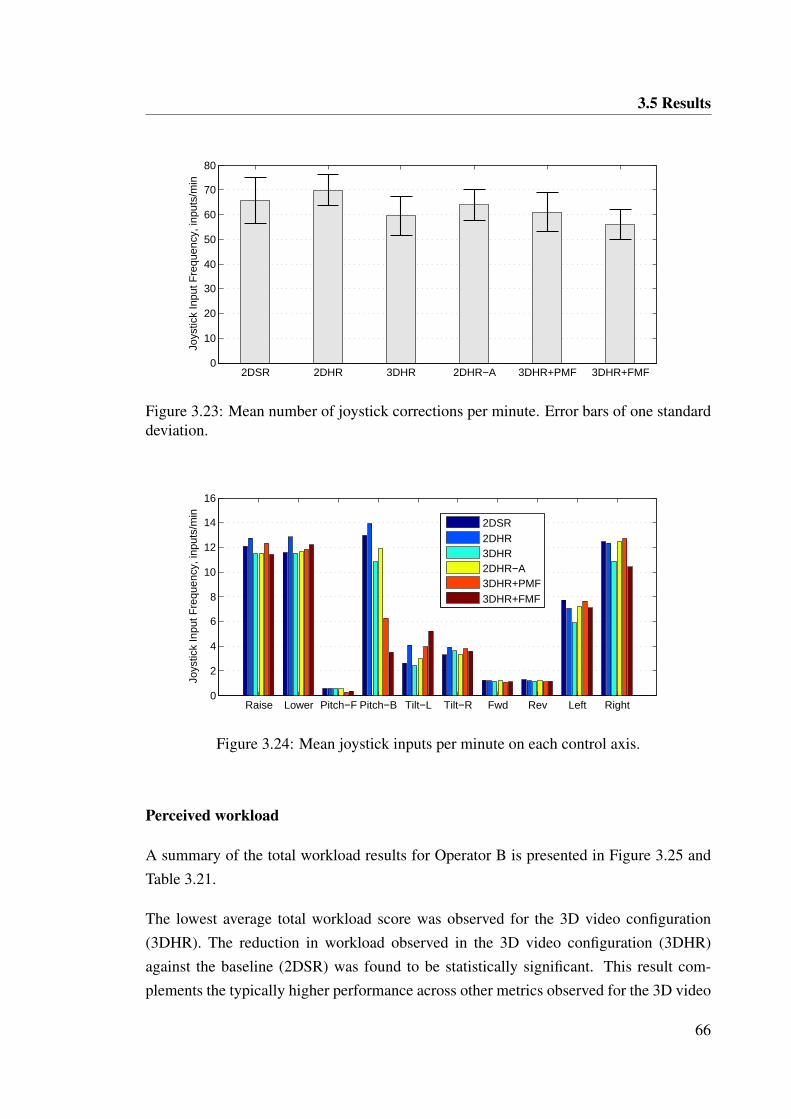
3.5 Results
2DSR 2DHR 3DHR 2DHR−A 3DHR+PMF 3DHR+FMF0
10
20
30
40
50
60
70
80
Joys
tick
Inpu
t Fre
quen
cy, i
nput
s/m
in
Figure 3.23: Mean number of joystick corrections per minute. Error bars of one standarddeviation.
Raise Lower Pitch−F Pitch−B Tilt−L Tilt−R Fwd Rev Left Right0
2
4
6
8
10
12
14
16
Joys
tick
Inpu
t Fre
quen
cy, i
nput
s/m
in
2DSR2DHR3DHR2DHR−A3DHR+PMF3DHR+FMF
Figure 3.24: Mean joystick inputs per minute on each control axis.
Perceived workload
A summary of the total workload results for Operator B is presented in Figure 3.25 andTable 3.21.
The lowest average total workload score was observed for the 3D video configuration(3DHR). The reduction in workload observed in the 3D video configuration (3DHR)against the baseline (2DSR) was found to be statistically significant. This result com-plements the typically higher performance across other metrics observed for the 3D video
66
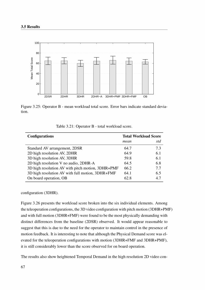
3.5 Results
2DSR 2DHR 3DHR 2DHR−A 3DHR+PMF 3DHR+FMF OB0
20
40
60
80
100
Mea
n T
otal
Sco
re
Figure 3.25: Operator B - mean workload total score. Error bars indicate standard devia-tion.
Table 3.21: Operator B - total workload score.
Configurations Total Workload Scoremean std
Standard AV arrangement, 2DSR 64.7 7.32D high resolution AV, 2DHR 64.9 6.13D high resolution AV, 3DHR 59.8 6.12D high resolution V no audio, 2DHR-A 64.5 6.83D high resolution AV with pitch motion, 3DHR+PMF 66.2 7.73D high resolution AV with full motion, 3DHR+FMF 64.1 6.5On board operation, OB 62.8 4.7
configuration (3DHR).
Figure 3.26 presents the workload score broken into the six individual elements. Amongthe teleoperation configurations, the 3D video configuration with pitch motion (3DHR+PMF)and with full motion (3DHR+FMF) were found to be the most physically demanding withdistinct differences from the baseline (2DSR) observed. It would appear reasonable tosuggest that this is due to the need for the operator to maintain control in the presence ofmotion feedback. It is interesting to note that although the Physical Demand score was el-evated for the teleoperation configurations with motion (3DHR+FMF and 3DHR+PMF),it is still considerably lower than the score observed for on board operation.
The results also show heightened Temporal Demand in the high resolution 2D video con-
67
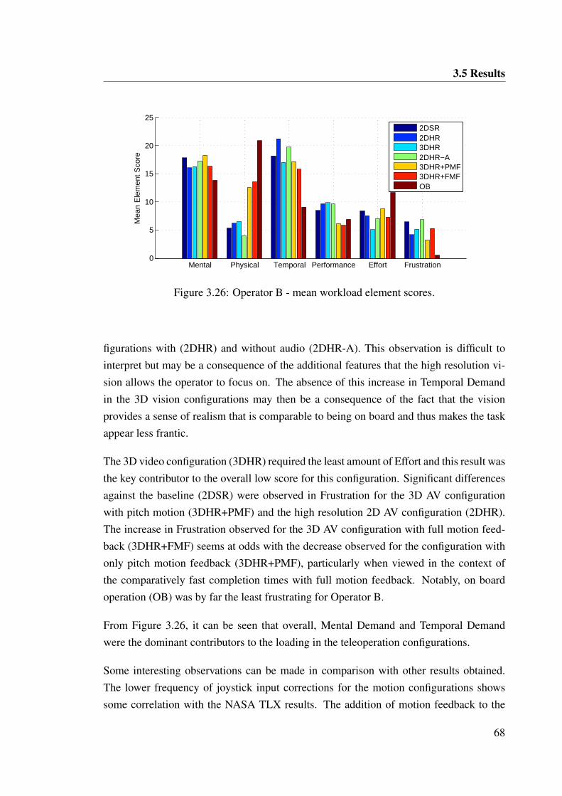
3.5 Results
Mental Physical Temporal Performance Effort Frustration0
5
10
15
20
25
Mea
n E
lem
ent S
core
2DSR2DHR3DHR2DHR−A3DHR+PMF3DHR+FMFOB
Figure 3.26: Operator B - mean workload element scores.
figurations with (2DHR) and without audio (2DHR-A). This observation is difficult tointerpret but may be a consequence of the additional features that the high resolution vi-sion allows the operator to focus on. The absence of this increase in Temporal Demandin the 3D vision configurations may then be a consequence of the fact that the visionprovides a sense of realism that is comparable to being on board and thus makes the taskappear less frantic.
The 3D video configuration (3DHR) required the least amount of Effort and this result wasthe key contributor to the overall low score for this configuration. Significant differencesagainst the baseline (2DSR) were observed in Frustration for the 3D AV configurationwith pitch motion (3DHR+PMF) and the high resolution 2D AV configuration (2DHR).The increase in Frustration observed for the 3D AV configuration with full motion feed-back (3DHR+FMF) seems at odds with the decrease observed for the configuration withonly pitch motion feedback (3DHR+PMF), particularly when viewed in the context ofthe comparatively fast completion times with full motion feedback. Notably, on boardoperation (OB) was by far the least frustrating for Operator B.
From Figure 3.26, it can be seen that overall, Mental Demand and Temporal Demandwere the dominant contributors to the loading in the teleoperation configurations.
Some interesting observations can be made in comparison with other results obtained.The lower frequency of joystick input corrections for the motion configurations showssome correlation with the NASA TLX results. The addition of motion feedback to the
68
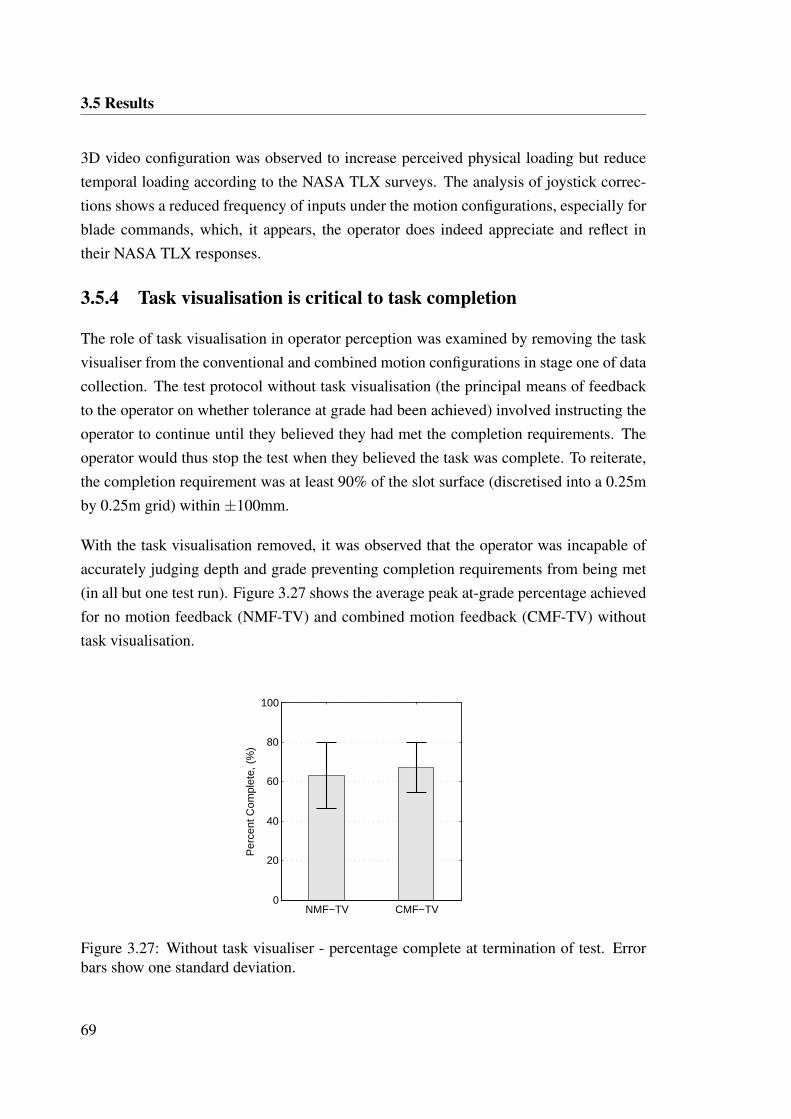
3.5 Results
3D video configuration was observed to increase perceived physical loading but reducetemporal loading according to the NASA TLX surveys. The analysis of joystick correc-tions shows a reduced frequency of inputs under the motion configurations, especially forblade commands, which, it appears, the operator does indeed appreciate and reflect intheir NASA TLX responses.
3.5.4 Task visualisation is critical to task completion
The role of task visualisation in operator perception was examined by removing the taskvisualiser from the conventional and combined motion configurations in stage one of datacollection. The test protocol without task visualisation (the principal means of feedbackto the operator on whether tolerance at grade had been achieved) involved instructing theoperator to continue until they believed they had met the completion requirements. Theoperator would thus stop the test when they believed the task was complete. To reiterate,the completion requirement was at least 90% of the slot surface (discretised into a 0.25mby 0.25m grid) within ±100mm.
With the task visualisation removed, it was observed that the operator was incapable ofaccurately judging depth and grade preventing completion requirements from being met(in all but one test run). Figure 3.27 shows the average peak at-grade percentage achievedfor no motion feedback (NMF-TV) and combined motion feedback (CMF-TV) withouttask visualisation.
NMF−TV CMF−TV0
20
40
60
80
100
Per
cent
Com
plet
e, (
%)
Figure 3.27: Without task visualiser - percentage complete at termination of test. Errorbars show one standard deviation.
69
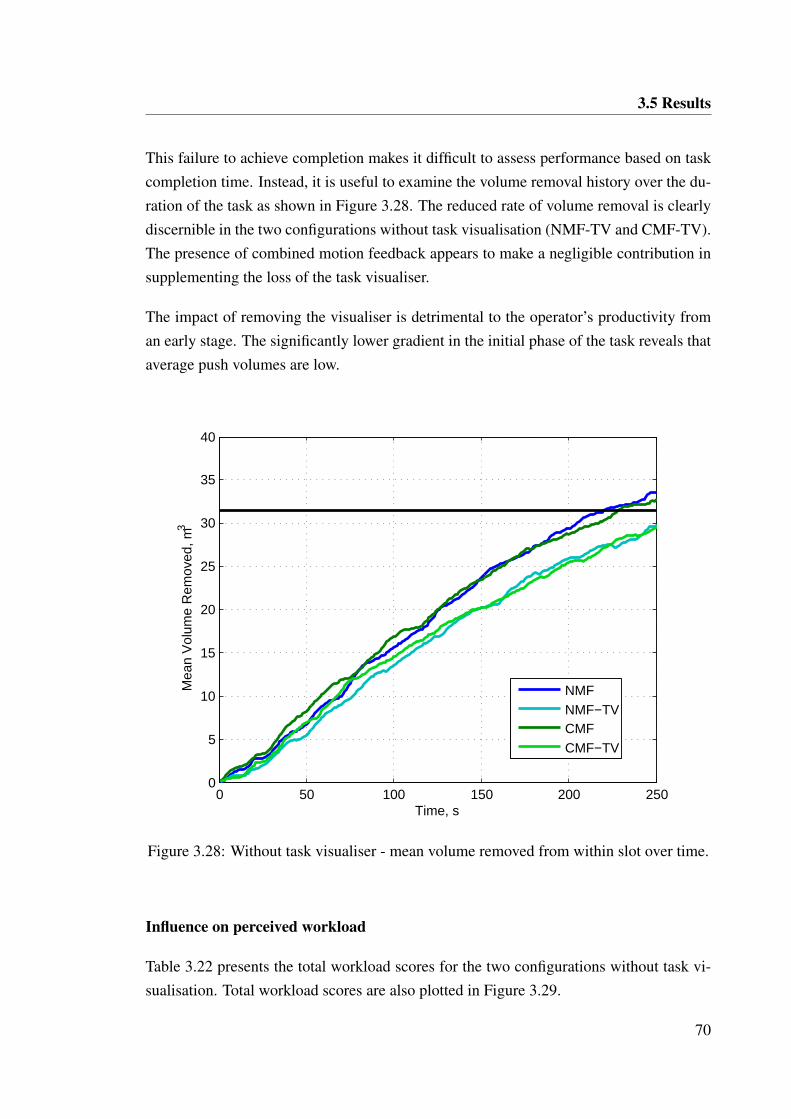
3.5 Results
This failure to achieve completion makes it difficult to assess performance based on taskcompletion time. Instead, it is useful to examine the volume removal history over the du-ration of the task as shown in Figure 3.28. The reduced rate of volume removal is clearlydiscernible in the two configurations without task visualisation (NMF-TV and CMF-TV).The presence of combined motion feedback appears to make a negligible contribution insupplementing the loss of the task visualiser.
The impact of removing the visualiser is detrimental to the operator’s productivity froman early stage. The significantly lower gradient in the initial phase of the task reveals thataverage push volumes are low.
0 50 100 150 200 2500
5
10
15
20
25
30
35
40
Time, s
Mea
n V
olum
e R
emov
ed, m
3
NMFNMF−TVCMFCMF−TV
Figure 3.28: Without task visualiser - mean volume removed from within slot over time.
Influence on perceived workload
Table 3.22 presents the total workload scores for the two configurations without task vi-sualisation. Total workload scores are also plotted in Figure 3.29.
70
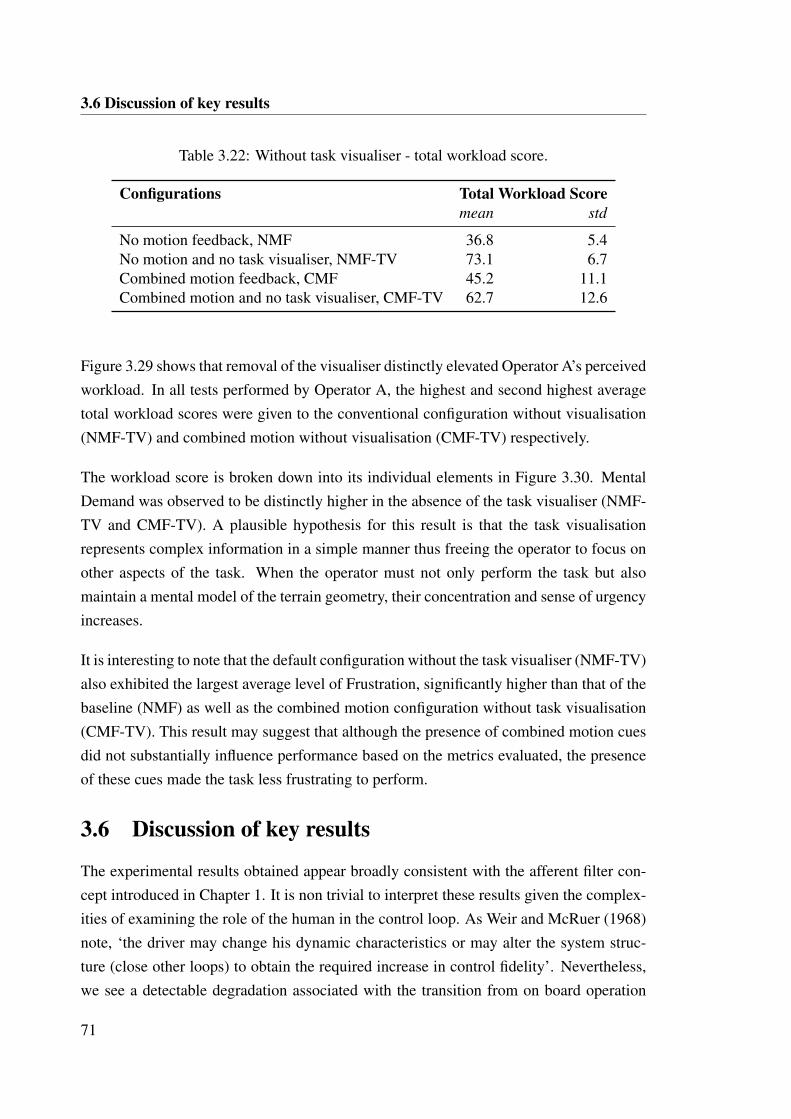
3.6 Discussion of key results
Table 3.22: Without task visualiser - total workload score.
Configurations Total Workload Scoremean std
No motion feedback, NMF 36.8 5.4No motion and no task visualiser, NMF-TV 73.1 6.7Combined motion feedback, CMF 45.2 11.1Combined motion and no task visualiser, CMF-TV 62.7 12.6
Figure 3.29 shows that removal of the visualiser distinctly elevated Operator A’s perceivedworkload. In all tests performed by Operator A, the highest and second highest averagetotal workload scores were given to the conventional configuration without visualisation(NMF-TV) and combined motion without visualisation (CMF-TV) respectively.
The workload score is broken down into its individual elements in Figure 3.30. MentalDemand was observed to be distinctly higher in the absence of the task visualiser (NMF-TV and CMF-TV). A plausible hypothesis for this result is that the task visualisationrepresents complex information in a simple manner thus freeing the operator to focus onother aspects of the task. When the operator must not only perform the task but alsomaintain a mental model of the terrain geometry, their concentration and sense of urgencyincreases.
It is interesting to note that the default configuration without the task visualiser (NMF-TV)also exhibited the largest average level of Frustration, significantly higher than that of thebaseline (NMF) as well as the combined motion configuration without task visualisation(CMF-TV). This result may suggest that although the presence of combined motion cuesdid not substantially influence performance based on the metrics evaluated, the presenceof these cues made the task less frustrating to perform.
3.6 Discussion of key results
The experimental results obtained appear broadly consistent with the afferent filter con-cept introduced in Chapter 1. It is non trivial to interpret these results given the complex-ities of examining the role of the human in the control loop. As Weir and McRuer (1968)note, ‘the driver may change his dynamic characteristics or may alter the system struc-ture (close other loops) to obtain the required increase in control fidelity’. Nevertheless,we see a detectable degradation associated with the transition from on board operation
71
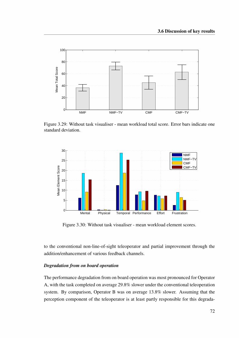
3.6 Discussion of key results
NMF NMF−TV CMF CMF−TV0
20
40
60
80
100
Mea
n T
otal
Sco
re
Figure 3.29: Without task visualiser - mean workload total score. Error bars indicate onestandard deviation.
Mental Physical Temporal Performance Effort Frustration0
5
10
15
20
25
30
Mea
n E
lem
ent S
core
NMFNMF−TVCMFCMF−TV
Figure 3.30: Without task visualiser - mean workload element scores.
to the conventional non-line-of-sight teleoperator and partial improvement through theaddition/enhancement of various feedback channels.
Degradation from on board operation
The performance degradation from on board operation was most pronounced for OperatorA, with the task completed on average 29.8% slower under the conventional teleoperationsystem. By comparison, Operator B was on average 13.8% slower. Assuming that theperception component of the teleoperator is at least partly responsible for this degrada-
72
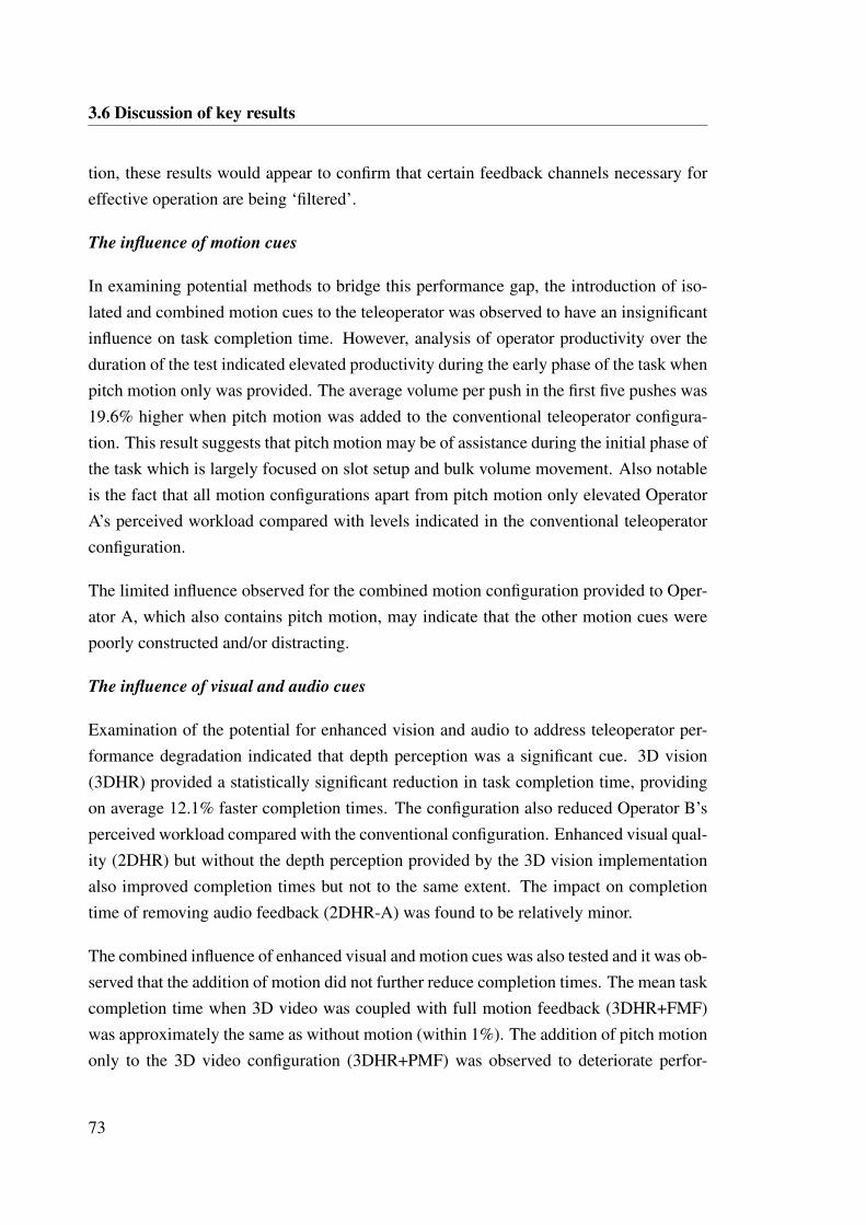
3.6 Discussion of key results
tion, these results would appear to confirm that certain feedback channels necessary foreffective operation are being ‘filtered’.
The influence of motion cues
In examining potential methods to bridge this performance gap, the introduction of iso-lated and combined motion cues to the teleoperator was observed to have an insignificantinfluence on task completion time. However, analysis of operator productivity over theduration of the test indicated elevated productivity during the early phase of the task whenpitch motion only was provided. The average volume per push in the first five pushes was19.6% higher when pitch motion was added to the conventional teleoperator configura-tion. This result suggests that pitch motion may be of assistance during the initial phase ofthe task which is largely focused on slot setup and bulk volume movement. Also notableis the fact that all motion configurations apart from pitch motion only elevated OperatorA’s perceived workload compared with levels indicated in the conventional teleoperatorconfiguration.
The limited influence observed for the combined motion configuration provided to Oper-ator A, which also contains pitch motion, may indicate that the other motion cues werepoorly constructed and/or distracting.
The influence of visual and audio cues
Examination of the potential for enhanced vision and audio to address teleoperator per-formance degradation indicated that depth perception was a significant cue. 3D vision(3DHR) provided a statistically significant reduction in task completion time, providingon average 12.1% faster completion times. The configuration also reduced Operator B’sperceived workload compared with the conventional configuration. Enhanced visual qual-ity (2DHR) but without the depth perception provided by the 3D vision implementationalso improved completion times but not to the same extent. The impact on completiontime of removing audio feedback (2DHR-A) was found to be relatively minor.
The combined influence of enhanced visual and motion cues was also tested and it was ob-served that the addition of motion did not further reduce completion times. The mean taskcompletion time when 3D video was coupled with full motion feedback (3DHR+FMF)was approximately the same as without motion (within 1%). The addition of pitch motiononly to the 3D video configuration (3DHR+PMF) was observed to deteriorate perfor-
73
3.6 Discussion of key results
mance in terms of task completion time.
However, the coupled 3D video and full motion feedback configuration was found to im-prove push productivity during the initial high-volume stage of the task. The average pushvolume during the first five pushes was 21.9% higher than in the conventional teleoperatorconfiguration.
The combination of the 3D vision with full motion feedback (3DHR+FMF) did not showreduced perceived workload for Operator B. However, the frequency of joystick inputswas found to be significantly reduced under the 3D visual configuration with (3DHR+FMF)and without (3DHR) full motion feedback. The frequency of joystick inputs is hypothe-sized to reflect operating style with reduced frequency indicating a more relaxed operatingstyle and reduced actual workload.
The influence of task visualisation
The role of visualisation in enabling execution of the structured task was found to becritical. When the visualisation was removed from the set of cues provided to the operator,they were unable to effectively determine completion criteria. In addition, removal oftask visualisation reduced push productivity in the initial phase of the task and elevatedperceived workload. This result suggests that the task visualisation makes a significantcontribution in supporting cut profile planning and therefore blade fill. This may indicatethat the visualiser provides useful feedback in positioning and orienting the bulldozer forhigh volume pushes during the early phase of the task.
In summary, the results obtained from experiments indicate that perception characteris-tics influence the multifaceted aspects of performance in many and complex ways. Thismakes it difficult to draw truly definitive conclusions on the impact of individual cues butdoes allow for some broad statements to be made. Among the cues involving remote per-ception replication, depth perception would appear to be the dominant factor influencingperformance with the benefits of 3D found to be particularly distinct. The provision ofmotion cues were observed to improve certain aspects of performance, i.e. early stagepush productivity. Task visualisation also plays a critical role in enabling effective plan-ning and task execution.
74
CHAPTER 4
Task analysis for bulldozer operation
4.1 Aim
This chapter examines the operation of a bulldozer from the perspective of determiningthe correspondence between feedback pathways and control actions. The aim of thisanalysis is to contextualise the effects observed in Chapter 3 within an appreciation of thefeedback pathways constructed by the operator.
The results obtained in Chapter 3, as well as task observation, targeted surveys and quali-tative operator feedback are used to formulate a perception-control model for the experi-mental task performed.
4.2 Linking perception to task behaviour
Identifying the links between perception and control actions first requires a method ofcapturing, describing and decomposing the bulldozer operation task. Interface designersperform task analysis to better understand the control activities of the user. A broad set oftechniques have emerged to assist in drawing out and describing tasks.
Kirwan and Ainsworth (1992) split the challenge of task and interface design into twostages: (i) determining what information must be supplied to permit understanding of thecurrent status and requirements of the system; and (ii) what actions and controls must beapplied by the operator to control the system. This provides the foundation for determin-ing how this information and control capability are best provided.
75
4.3 Modelling the human
A commonly used task analysis technique is Cognitive Task Analysis (CTA). Hoffmanand Militello (2008) define CTA as, ‘the determination of the cognitive skills, strategiesand the knowledge required to perform tasks’. Cognitive Task Analysis can be achievedthrough operator interviews with questions targeted at three key areas: the concepts im-portant to the domain and how they are related; the procedures that are followed andhow various reasoning ‘rules’ govern these procedures; and the exception cases in whichspecial procedures are required (Hoffman and Militello, 2008).
Once such task analysis has been performed, there are a variety of techniques available todecompose and represent this information. A popular method of describing work organi-sation is hierarchical task analysis (HTA). HTA captures the operations that are performedas part of a task as well as the plans that represent the conditions under which operationsare performed. The HTA applies a hierarchy that permits specification of operations withdifferent levels of detail. The traditional purpose of such analysis is to ‘identify actual orpossible sources of performance failure and to propose suitable remedies’ (Annett, 2010).While this express purpose is not exactly the intent in the case under consideration, theformal process is still relevant in applying decompositional thinking to the task in orderto identify its elemental components.
4.3 Modelling the human
As described in Section1.4.5, there has been significant effort applied to creating humanmodels of control and behaviour. Pilot or driver models have been developed to both betterunderstand the role of the human in a control system and to support vehicle design throughmodelling closed loop performance. These pilot models attempt to explain how humanstake various inputs and convert them into appropriate control actions. Such models rangefrom relatively simple disturbance rejection control of path errors in driving a vehicle(Weir and McRuer, 1968) up to highly detailed models that seek to capture each stagein the sensory process (McRuer and Krendel, 1965). Driver/pilot models continue to beused in assessment of vehicle dynamics and fidelity assessment of simulators.
Another area of focus for researchers of perception-to-action modelling is the concept ofSituation Awareness. Endsley (1995) defines Situation Awareness as, ‘the perception ofthe elements in the environment within a volume of time and space, the comprehension oftheir meaning, and the projection of their status in the near future’. Situation Awareness(SA) is considered a key aspect of task behaviour and determinant of performance.
76
4.4 Analysis of bulldozer operation and teleoperation
According to Endsley (1995), consideration of SA represents a step beyond the simplis-tic view of the human as a processor of inputs to yield appropriate control outputs. AsEndsley (1995) notes, ‘operators must do more than simply perceive the state of theirenvironment. They must understand the integrated meaning of what they are perceivingin light of their goals.’ It is important to recognise the separation that the concept of SAseeks to enforce between comprehension and decision: perfect comprehension can stilllead to an incorrect decision and imperfect comprehension may lead to a decision that istheoretically correct given that comprehension but not appropriate for the ‘true’ situation.
Endsley (1995) describes a three level model of SA as illustrated in Figure 4.1. Level 1is perception of the current situation. Level 2 is comprehension of the current situation.Level 3 is projection to determine future status. To explain these levels within the contextof bulldozer operation, let us examine the situation in which the operator perceives sud-den and excessive pitching of the bulldozer (level 1). The operator comprehends that theblade has cut too deep (level 2). Appreciating this, the operator projects that in the nextreverse phase there may be a need to avoid impact due to see-sawing over the edge of thebeginning of the steep gradient created (level 3). The separation into these levels suggeststhat training and experience become more important in making each level transition. Ithas been observed (Klein, 1993) that in time critical tasks, conscious deliberation of al-ternative solutions is rare. Instead people recognise the most appropriate action based onestablished experience in similar situations. However, there is a tendency back towardsthe analytical model when there is disputed information.
4.4 Analysis of bulldozer operation and teleoperation
The literature provides a variety of useful frameworks and theoretical models for exam-ining and capturing the perception-to-control-action behaviour of the bulldozer operator.The following sections present the results of an investigation of the operators’ qualitativeassessment of their own perception and control behaviour. These results as well as thefindings of Chapter 3 are used to develop a task model and ultimately a perception-to-control model for the bulldozer operator.
4.4.1 Task and cue surveys
After completion of each test in the experiments described in Chapter 3, the operator wasgiven a one page survey to complete. The survey presented a series of statements to which
77
4.4 Analysis of bulldozer operation and teleoperation
Task/System Factors
Individual Factors
•ESystemECapability•EInterfaceEDesign•EStressEvEWorkload•EComplexity•EAutomation
DecisionPerformance
OfEActions
PerceptionOfEElementsInECurrentSituation
Level 1
ComprehensionOfECurrentSituation
Level 2
ProjectionOfEFutureStatus
Level 3
•EAbilities•EExperience•ETraining
•EGoalsEvEObjectives•EPreconceptions•E)ExpectationsL LongETerm
MemoryEStoresAutomaticity
InformationEProcessingMechanisms
Feedback
StateEOfETheEnvironment
Situation Awareness
Figure 4.1: Situation awareness model (figure recreated based on Endsley (1995)).
the operator indicated their level of agreement or disagreement. The level of agreementwith the statement was scored on a scale between strongly disagree (1) and strongly agree(10). The survey was split into two sections: questions related to performing the task andquestions related to perceiving relevant operational cues. The task focus section targetsthe ability of the operator to complete the assigned task while the cue focus section isconcerned with the different kinds of adjustments the operator is able to make based onthe cues provided to them.
The exact questions used in the survey differed slightly between stage one and two of datacollection based on the perception factors in focus. A section for general feedback was
78
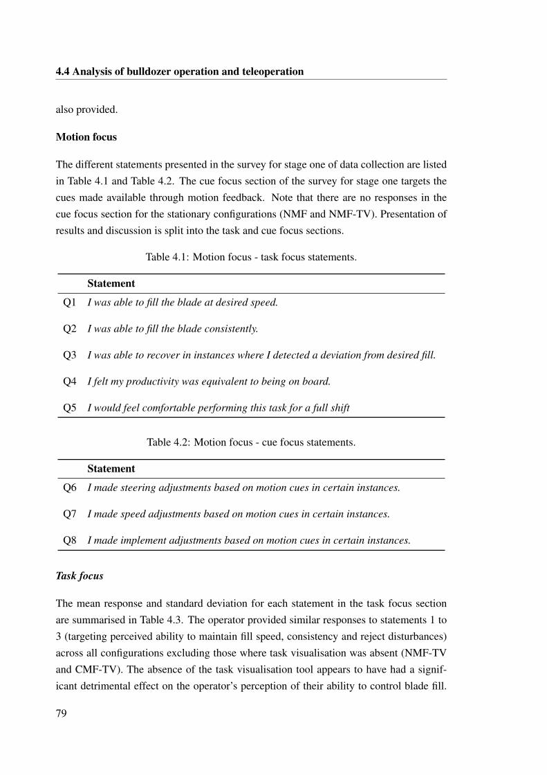
4.4 Analysis of bulldozer operation and teleoperation
also provided.
Motion focus
The different statements presented in the survey for stage one of data collection are listedin Table 4.1 and Table 4.2. The cue focus section of the survey for stage one targets thecues made available through motion feedback. Note that there are no responses in thecue focus section for the stationary configurations (NMF and NMF-TV). Presentation ofresults and discussion is split into the task and cue focus sections.
Table 4.1: Motion focus - task focus statements.
Statement
Q1 I was able to fill the blade at desired speed.
Q2 I was able to fill the blade consistently.
Q3 I was able to recover in instances where I detected a deviation from desired fill.
Q4 I felt my productivity was equivalent to being on board.
Q5 I would feel comfortable performing this task for a full shift
Table 4.2: Motion focus - cue focus statements.
Statement
Q6 I made steering adjustments based on motion cues in certain instances.
Q7 I made speed adjustments based on motion cues in certain instances.
Q8 I made implement adjustments based on motion cues in certain instances.
Task focus
The mean response and standard deviation for each statement in the task focus sectionare summarised in Table 4.3. The operator provided similar responses to statements 1 to3 (targeting perceived ability to maintain fill speed, consistency and reject disturbances)across all configurations excluding those where task visualisation was absent (NMF-TVand CMF-TV). The absence of the task visualisation tool appears to have had a signif-icant detrimental effect on the operator’s perception of their ability to control blade fill.
79
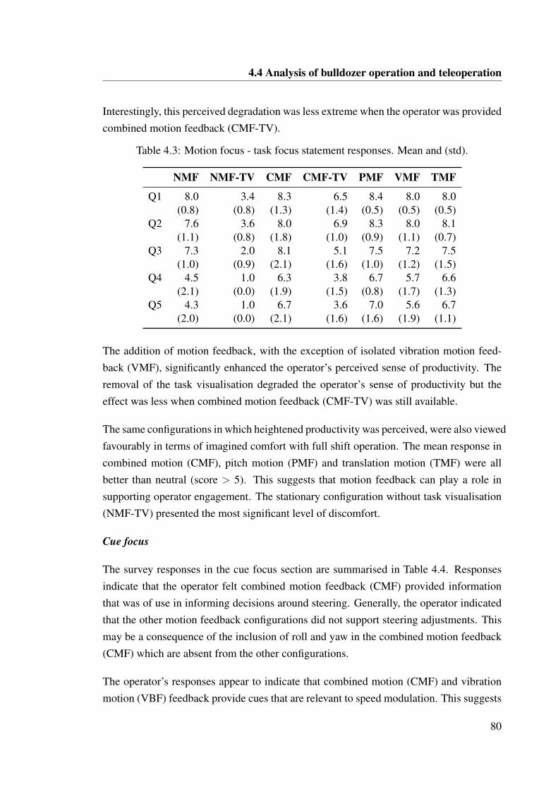
4.4 Analysis of bulldozer operation and teleoperation
Interestingly, this perceived degradation was less extreme when the operator was providedcombined motion feedback (CMF-TV).
Table 4.3: Motion focus - task focus statement responses. Mean and (std).
NMF NMF-TV CMF CMF-TV PMF VMF TMF
Q1 8.0 3.4 8.3 6.5 8.4 8.0 8.0(0.8) (0.8) (1.3) (1.4) (0.5) (0.5) (0.5)
Q2 7.6 3.6 8.0 6.9 8.3 8.0 8.1(1.1) (0.8) (1.8) (1.0) (0.9) (1.1) (0.7)
Q3 7.3 2.0 8.1 5.1 7.5 7.2 7.5(1.0) (0.9) (2.1) (1.6) (1.0) (1.2) (1.5)
Q4 4.5 1.0 6.3 3.8 6.7 5.7 6.6(2.1) (0.0) (1.9) (1.5) (0.8) (1.7) (1.3)
Q5 4.3 1.0 6.7 3.6 7.0 5.6 6.7(2.0) (0.0) (2.1) (1.6) (1.6) (1.9) (1.1)
The addition of motion feedback, with the exception of isolated vibration motion feed-back (VMF), significantly enhanced the operator’s perceived sense of productivity. Theremoval of the task visualisation degraded the operator’s sense of productivity but theeffect was less when combined motion feedback (CMF-TV) was still available.
The same configurations in which heightened productivity was perceived, were also viewedfavourably in terms of imagined comfort with full shift operation. The mean response incombined motion (CMF), pitch motion (PMF) and translation motion (TMF) were allbetter than neutral (score > 5). This suggests that motion feedback can play a role insupporting operator engagement. The stationary configuration without task visualisation(NMF-TV) presented the most significant level of discomfort.
Cue focus
The survey responses in the cue focus section are summarised in Table 4.4. Responsesindicate that the operator felt combined motion feedback (CMF) provided informationthat was of use in informing decisions around steering. Generally, the operator indicatedthat the other motion feedback configurations did not support steering adjustments. Thismay be a consequence of the inclusion of roll and yaw in the combined motion feedback(CMF) which are absent from the other configurations.
The operator’s responses appear to indicate that combined motion (CMF) and vibrationmotion (VBF) feedback provide cues that are relevant to speed modulation. This suggests
80
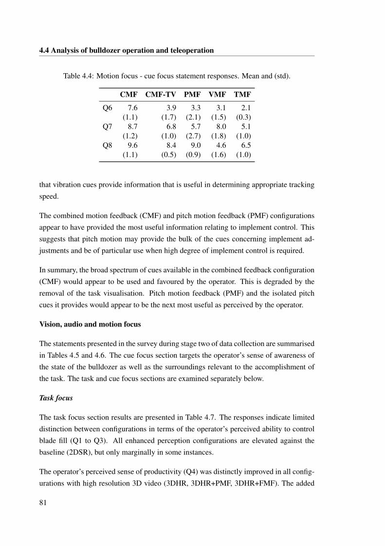
4.4 Analysis of bulldozer operation and teleoperation
Table 4.4: Motion focus - cue focus statement responses. Mean and (std).
CMF CMF-TV PMF VMF TMF
Q6 7.6 3.9 3.3 3.1 2.1(1.1) (1.7) (2.1) (1.5) (0.3)
Q7 8.7 6.8 5.7 8.0 5.1(1.2) (1.0) (2.7) (1.8) (1.0)
Q8 9.6 8.4 9.0 4.6 6.5(1.1) (0.5) (0.9) (1.6) (1.0)
that vibration cues provide information that is useful in determining appropriate trackingspeed.
The combined motion feedback (CMF) and pitch motion feedback (PMF) configurationsappear to have provided the most useful information relating to implement control. Thissuggests that pitch motion may provide the bulk of the cues concerning implement ad-justments and be of particular use when high degree of implement control is required.
In summary, the broad spectrum of cues available in the combined feedback configuration(CMF) would appear to be used and favoured by the operator. This is degraded by theremoval of the task visualisation. Pitch motion feedback (PMF) and the isolated pitchcues it provides would appear to be the next most useful as perceived by the operator.
Vision, audio and motion focus
The statements presented in the survey during stage two of data collection are summarisedin Tables 4.5 and 4.6. The cue focus section targets the operator’s sense of awareness ofthe state of the bulldozer as well as the surroundings relevant to the accomplishment ofthe task. The task and cue focus sections are examined separately below.
Task focus
The task focus section results are presented in Table 4.7. The responses indicate limiteddistinction between configurations in terms of the operator’s perceived ability to controlblade fill (Q1 to Q3). All enhanced perception configurations are elevated against thebaseline (2DSR), but only marginally in some instances.
The operator’s perceived sense of productivity (Q4) was distinctly improved in all config-urations with high resolution 3D video (3DHR, 3DHR+PMF, 3DHR+FMF). The added
81
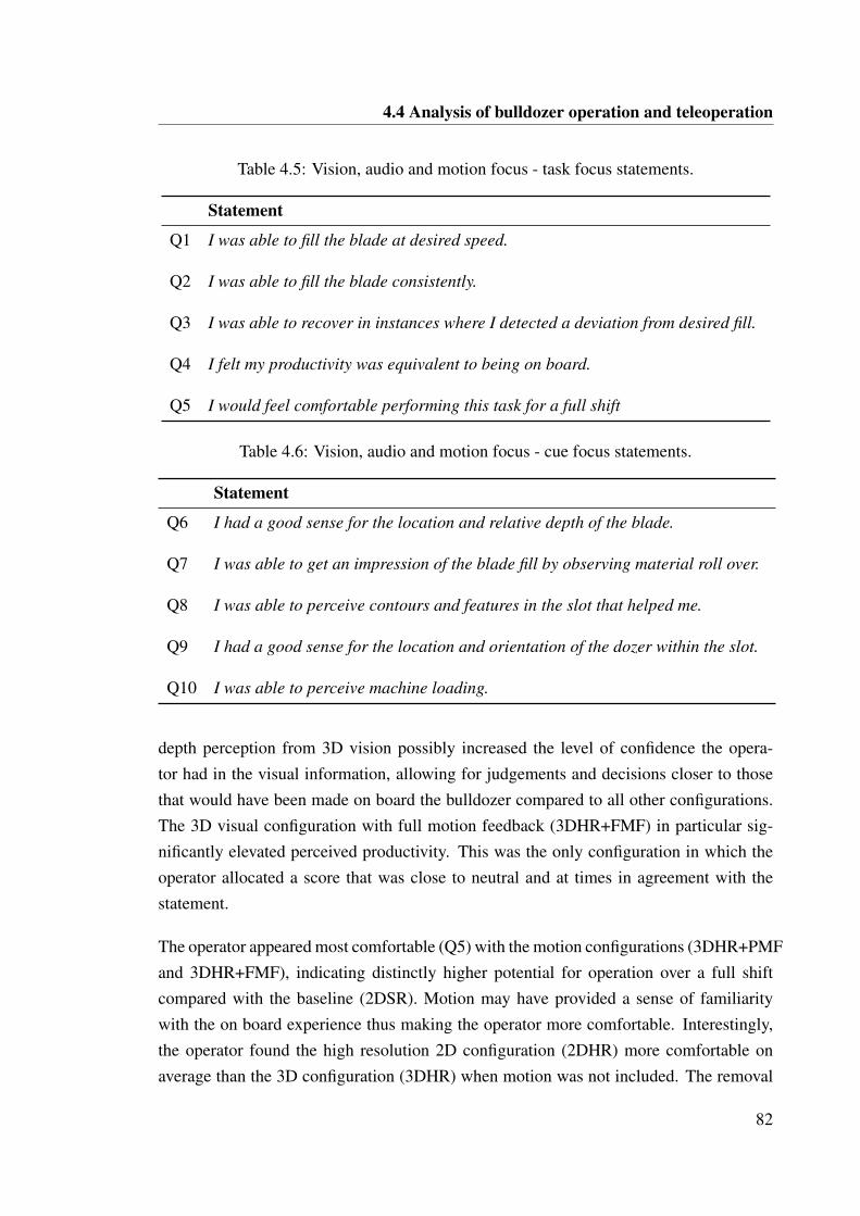
4.4 Analysis of bulldozer operation and teleoperation
Table 4.5: Vision, audio and motion focus - task focus statements.
Statement
Q1 I was able to fill the blade at desired speed.
Q2 I was able to fill the blade consistently.
Q3 I was able to recover in instances where I detected a deviation from desired fill.
Q4 I felt my productivity was equivalent to being on board.
Q5 I would feel comfortable performing this task for a full shift
Table 4.6: Vision, audio and motion focus - cue focus statements.
Statement
Q6 I had a good sense for the location and relative depth of the blade.
Q7 I was able to get an impression of the blade fill by observing material roll over.
Q8 I was able to perceive contours and features in the slot that helped me.
Q9 I had a good sense for the location and orientation of the dozer within the slot.
Q10 I was able to perceive machine loading.
depth perception from 3D vision possibly increased the level of confidence the opera-tor had in the visual information, allowing for judgements and decisions closer to thosethat would have been made on board the bulldozer compared to all other configurations.The 3D visual configuration with full motion feedback (3DHR+FMF) in particular sig-nificantly elevated perceived productivity. This was the only configuration in which theoperator allocated a score that was close to neutral and at times in agreement with thestatement.
The operator appeared most comfortable (Q5) with the motion configurations (3DHR+PMFand 3DHR+FMF), indicating distinctly higher potential for operation over a full shiftcompared with the baseline (2DSR). Motion may have provided a sense of familiaritywith the on board experience thus making the operator more comfortable. Interestingly,the operator found the high resolution 2D configuration (2DHR) more comfortable onaverage than the 3D configuration (3DHR) when motion was not included. The removal
82
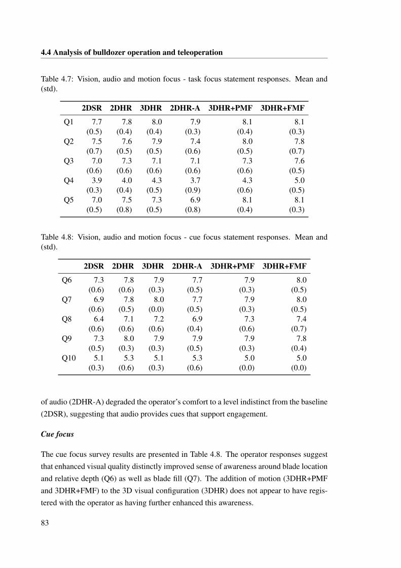
4.4 Analysis of bulldozer operation and teleoperation
Table 4.7: Vision, audio and motion focus - task focus statement responses. Mean and(std).
2DSR 2DHR 3DHR 2DHR-A 3DHR+PMF 3DHR+FMF
Q1 7.7 7.8 8.0 7.9 8.1 8.1(0.5) (0.4) (0.4) (0.3) (0.4) (0.3)
Q2 7.5 7.6 7.9 7.4 8.0 7.8(0.7) (0.5) (0.5) (0.6) (0.5) (0.7)
Q3 7.0 7.3 7.1 7.1 7.3 7.6(0.6) (0.6) (0.6) (0.6) (0.6) (0.5)
Q4 3.9 4.0 4.3 3.7 4.3 5.0(0.3) (0.4) (0.5) (0.9) (0.6) (0.5)
Q5 7.0 7.5 7.3 6.9 8.1 8.1(0.5) (0.8) (0.5) (0.8) (0.4) (0.3)
Table 4.8: Vision, audio and motion focus - cue focus statement responses. Mean and(std).
2DSR 2DHR 3DHR 2DHR-A 3DHR+PMF 3DHR+FMF
Q6 7.3 7.8 7.9 7.7 7.9 8.0(0.6) (0.6) (0.3) (0.5) (0.3) (0.5)
Q7 6.9 7.8 8.0 7.7 7.9 8.0(0.6) (0.5) (0.0) (0.5) (0.3) (0.5)
Q8 6.4 7.1 7.2 6.9 7.3 7.4(0.6) (0.6) (0.6) (0.4) (0.6) (0.7)
Q9 7.3 8.0 7.9 7.9 7.9 7.8(0.5) (0.3) (0.3) (0.5) (0.3) (0.4)
Q10 5.1 5.3 5.1 5.3 5.0 5.0(0.3) (0.6) (0.3) (0.6) (0.0) (0.0)
of audio (2DHR-A) degraded the operator’s comfort to a level indistinct from the baseline(2DSR), suggesting that audio provides cues that support engagement.
Cue focus
The cue focus survey results are presented in Table 4.8. The operator responses suggestthat enhanced visual quality distinctly improved sense of awareness around blade locationand relative depth (Q6) as well as blade fill (Q7). The addition of motion (3DHR+PMFand 3DHR+FMF) to the 3D visual configuration (3DHR) does not appear to have regis-tered with the operator as having further enhanced this awareness.
83
4.4 Analysis of bulldozer operation and teleoperation
The improved visual quality appears to have also elevated the operator’s perceived abilityto identify contours and features within the slot (Q8). The 3D configurations performedmarginally better than the 2D configurations. The configurations with motion feedbackreceived the highest mean scoring.
Similarly, enhanced visual quality appears to have elevated the operator’s sense of thelocation and orientation of the bulldozer (Q9). This sense appears slightly degraded withthe addition of full motion feedback (3DHR+FMF), possibly suggesting that the diversityof the motion cues can at times be confusing and difficult to resolve.
No distinct differences were observed between configurations with respect to the oper-ator’s perceived ability to discern machine loading (Q10). The slight elevation in themean response for the high resolution 2D video without audio (2DHR-A) configurationis confounding when considering the assumption that qualitative feedback from operatorssuggest that audio provides a useful cue in detecting machine loading.
4.4.2 Operator feedback
Operator feedback was collected throughout the execution of all tests in post block in-terview sessions. Questions focussed on which cues were considered important and howdifferent cues were used and transformed into command decisions.
Operator A
The following points represent a consolidation of feedback provided in interviews withOperator A. The points are a summary of the operator’s opinion.
• Pitch is the most important and beneficial motion feedback cue. It supports bladelift decisions particularly around slot entry and exit. It highlights areas where thereare significant deviations from a flat floor. It provides information that is useful inestablishing an optimal spoil pile.
• Roll is useful in certain circumstances but distracting in others. On the whole, rollis not particularly beneficial for the task being executed. Motion feedback is notdisorienting without roll.
• Yaw is useful in certain circumstances but distracting in others. Yaw is most usefulfor detecting when the edge of the blade has caught the side of the slot causing the
84
4.4 Analysis of bulldozer operation and teleoperation
machine to swing about. On the whole, yaw is not particularly beneficial for thetask being executed. Motion feedback is not disorienting without yaw.
• Vibration is a useful cue but less important than pitch. The information it providesaround track slip is used to perform blade lift and/or throttle commands. The vibra-tion cues can be processed and incorporated without significant mental effort andtherefore provides useful information without being distracting.
• Translation is a useful cue but is less important than pitch. Translation feedback pro-vides some information about bogging down and highlights directional changes. Aswith vibration, the information provided by translation feedback can be processedand incorporated without significant mental effort.
Operator B
The following points represent a consolidation of feedback provided in interviews withOperator B. The points are a summary of the operator’s opinion.
• The 3D high resolution video is the most favoured of all visual configurations. The3D visual implementation provides access to the majority of the visual cues thatwould be seen in the bulldozer itself.
• The high resolution video feeds provide superior vision of the amount of materialbeing carried by the blade. This information supports better decisions around rais-ing or lowering the blade, or modulating speed to adjust how much load is beingcarried.
• Depth perception provided by the 3D video feed allows better appreciation of prox-imity to slot walls and position within the slot. This supported more accurate cor-rections and appropriate timing.
• No dizziness, headaches or eye pain were experienced while wearing the 3D glasses.
• The 3D video feed had the highest mental loading due to the amount of visual cuesavailable.
• The stereo audio provided cues indicating track slip that are more difficult to detectonly through video. The pitch of the drive whine can also be utilised to discern
85
4.5 Modelling bulldozer control behaviour
engine and blade loading. Without audio, concentration levels were elevated, re-quiring greater focus on vision.
• Pitch provided cues relating to cut depth and slot geometry. The pitch responsewhen cutting can be used to quantify the relative depth achieved. The pitch cue alsogives good indication of slot entry and exit geometry.
• The roll cue is not regarded as being as important as pitch, but its presence waspreferred. It was considered useful in discerning lateral grade.
• Vibration was the most important motion feedback cue. The same cues are obtainedfrom the replicated vibration but without the aggressive motion of being on boardthe bulldozer.
• Translational acceleration motion is helpful in providing an accurate feeling of thestate of the bulldozer. This cue provided an accurate feeling of motion and usefulfeedback when overcutting.
• It was easier to see past shadows using the enhanced vision, particularly in the 3Dconfiguration.
4.5 Modelling bulldozer control behaviour
The execution of a slot bulldozing operation involves multiple coordinated activities. Thecontrol behaviour of the operator must adjust according to the specific requirements ata given stage of the operation. The operator switches between six operational states toexecute the overall task goal. These are:
1. Aligning - Lining up with the planned slot boundaries2. Entering - Driving into the slot up to the point of beginning to cut3. Cutting - Executing a desired cut trajectory4. Carrying - Pushing cut material through the slot to the dump point5. Dumping - Unloading material from the blade at the dump point6. Reversing - Returning to the start point for the next push
Figure 4.2 presents a state transition model of this behaviour. This state model providesa starting point for the Hierarchical Task Analysis (HTA). Each state corresponds to a
86
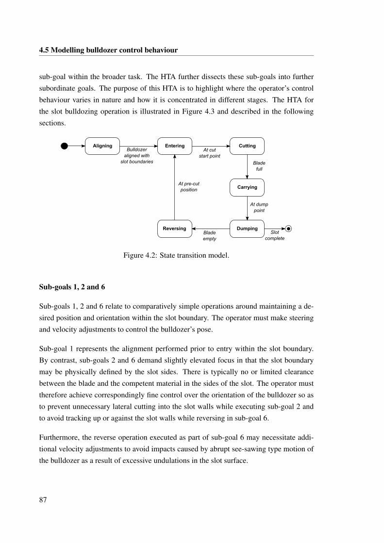
4.5 Modelling bulldozer control behaviour
sub-goal within the broader task. The HTA further dissects these sub-goals into furthersubordinate goals. The purpose of this HTA is to highlight where the operator’s controlbehaviour varies in nature and how it is concentrated in different stages. The HTA forthe slot bulldozing operation is illustrated in Figure 4.3 and described in the followingsections.
Aligning Entering Cutting
DumpingReversing
Carrying
Slot
complete
Bulldozer
aligned with
slot boundaries
At cut
start point
Blade
empty
Blade
full
At dump
point
At pre-cut
position
Figure 4.2: State transition model.
Sub-goals 1, 2 and 6
Sub-goals 1, 2 and 6 relate to comparatively simple operations around maintaining a de-sired position and orientation within the slot boundary. The operator must make steeringand velocity adjustments to control the bulldozer’s pose.
Sub-goal 1 represents the alignment performed prior to entry within the slot boundary.By contrast, sub-goals 2 and 6 demand slightly elevated focus in that the slot boundarymay be physically defined by the slot sides. There is typically no or limited clearancebetween the blade and the competent material in the sides of the slot. The operator musttherefore achieve correspondingly fine control over the orientation of the bulldozer so asto prevent unnecessary lateral cutting into the slot walls while executing sub-goal 2 andto avoid tracking up or against the slot walls while reversing in sub-goal 6.
Furthermore, the reverse operation executed as part of sub-goal 6 may necessitate addi-tional velocity adjustments to avoid impacts caused by abrupt see-sawing type motion ofthe bulldozer as a result of excessive undulations in the slot surface.
87
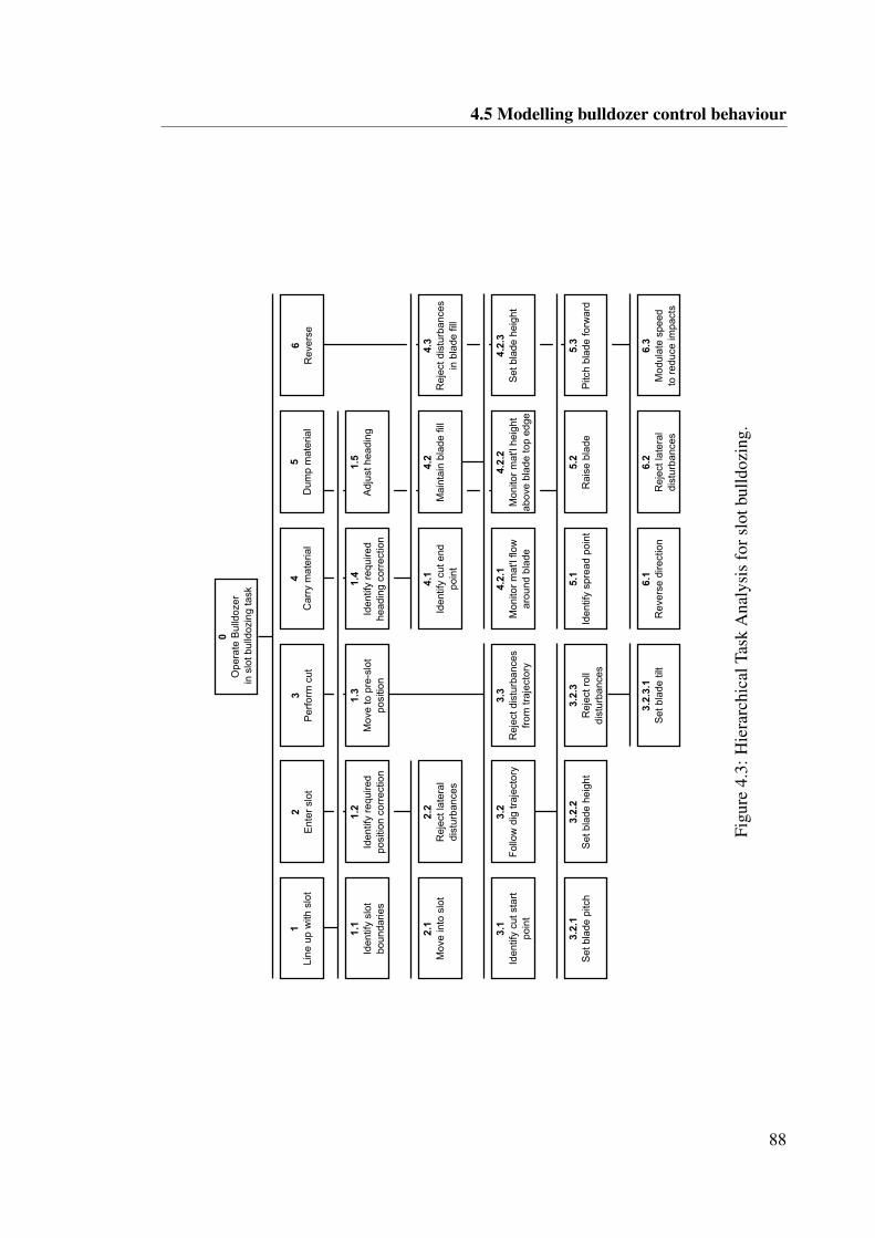
4.5 Modelling bulldozer control behaviour
0O
pera
tevB
ulld
ozer
vinvs
lotvb
ulld
ozi
ngvta
sk
1Li
nevu
pvw
ithvs
lot
2E
nter
vslo
t3
Per
form
vcut
4C
arry
vmat
eria
l5
Dum
pvm
ater
ial
6R
ever
se
1.1
Iden
tifyv
slot
vbo
unda
ries
1.2
Iden
tifyv
requ
ired
posi
tionv
corr
ectio
n
1.3
Mov
evto
vpre
-slo
tpo
sitio
n
1.4
Iden
tifyv
requ
ired
head
ingv
corr
ect
ion
1.5
Adj
ustvh
eadi
ng
2.1
Mov
evin
tovs
lot
2.2
Rej
ectvl
ater
aldi
stur
banc
es
3.1
Iden
tifyv
cutvs
tart
poin
t
3.2.1
Set
vbla
devp
itch
3.2.2
Set
vbla
devh
eigh
t
3.2
Fol
low
vdig
vtraj
ecto
ry3.3
Rej
ectvd
istu
rban
ces
from
vtraj
ecto
ry
3.2.3
Rej
ectvr
oll
dist
urba
nces
3.2.3.1
Set
vbla
devti
lt
4.1
Iden
tifyv
cutve
ndpo
int
4.2
Mai
ntai
nvbl
adev
fill
4.3
Rej
ectvd
istu
rban
ces
invb
lade
vfill
4.2.1
Mon
itorv
mat
Slvflo
war
oun
dvbl
ade
4.2.2
Mon
itorv
mat
Slvhe
ight
abov
evbl
ade
vtopv
edge
4.2.3
Set
vbla
devh
eigh
t
5.1
Iden
tifyv
spre
advp
oint
5.2
Rai
sevb
lade
5.3
Pitc
hvbl
adev
forw
ard
6.1
Rev
erse
vdire
ctio
n6.2
Rej
ectvl
ater
aldi
stur
banc
es
6.3
Mod
ulat
evsp
eed
tovr
educ
evim
pact
s
Figu
re4.
3:H
iera
rchi
calT
ask
Ana
lysi
sfo
rslo
tbul
ldoz
ing.
88
4.5 Modelling bulldozer control behaviour
Sub-goal 3
Sub-goal 3, Perform cut, is arguably the most involved task in executing the slot. Theoperation requires selection and following of the required dig trajectory. Following therequired dig trajectory involves modulating blade height and pitch. The competent mate-rial typically prevents precise tracking and random disturbances must be rejected.
Loading on the bulldozer must also be considered. Excessive cutting may lead to exces-sive loading and cause a loss of traction. The operator must monitor loading to reduceinstances of traction loss and correct for this when it occurs.
In addition to rejecting disturbances from the required dig trajectory, the operator mustalso reject any roll and lateral disturbances.
Sub-goal 4
Once competent material has been cut, it must be carried to the end of the slot. Theloading of the carried material on the blade alters the dynamic response of the bulldozer.The control response is subsequently affected and this must be accommodated by theoperator.
A key sub-goal during the carry stage is maintaining blade fill. The operator must makeblade adjustments to prevent losing material and also to prevent further cutting. Thisactivity requires fine control of blade height.
While carrying material, the operator must also attempt to reject any roll and lateral dis-turbance.
Sub-goal 5
After the material has been carried through the slot, it must be spread or dumped into apile. The operator must determine the desired dump point for the current push, recognis-ing that subsequent pushes may follow. Successive pushes will typically help build up apile that can also be used as a ramp for subsequent dumping into clear space. The efficientdumping of material is closely related to the geometry of this outramp. A ramp that is toosteep is inefficient in that material must be lifted higher against gravity. A ramp that is notsteep enough is inefficient in that material must be pushed over a longer distance.
Once the dump point has been reached, the operator must release material by raising and
89
4.6 Mapping perception to control
pitching the blade forward. After all material has been dumped, the operator transitionsto reverse.
4.6 Mapping perception to control
The hierarchical task analysis (HTA) highlights the various control demands on the op-erator. It provides a basis for the proposed control model and exploring the relationshipbetween perception and control actions.
The operator, the bulldozer and the environment are the three parts that together form theclosed-loop vehicle element. The commanded input to the operator is the desired slotgeometry. In addition, any environmental features or obstacles represent an external inputto the operator.
A multiloop model is proposed in which there is a main outerloop focused on path / tra-jectory control and three inner loops managing subsidiary aspects of the bulldozer controltask. These four feedback loops are:
1. Path / trajectory motions2. Angular motions3. Machine loading4. Blade loading
The model presented attempts to describe the on board operation of the bulldozer, per-mitting a theoretical assessment of introducing a teleoperator. This model is illustrated inFigure 4.4. This model has been developed with strong influences from Weir and McRuer(1968).
The feedback pathways illustrated in Figure 4.4 are examined in more detail below. Theimpact on these feedback pathways of transitioning from on board operation to teleoper-ation is also discussed.
90
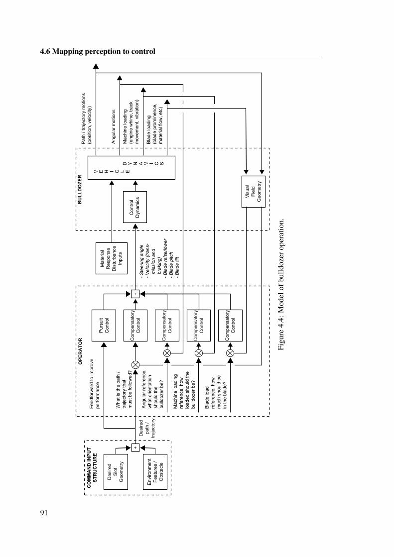
4.6 Mapping perception to control
BU
LL
DO
ZE
R
D Y N A M I C S
V E H I C L EC
ontr
olD
ynam
ics
Mat
eria
lR
espo
nse
Dis
turb
anc
eIn
puts
Vis
ual
Fie
ldG
eom
etry
OP
ER
AT
OR
CO
MM
AN
D IN
PU
TS
TR
UC
TU
RE
Des
ired
Slo
t G
eom
etry
Pur
suit
Con
trol
Com
pens
ator
yC
ontr
ol
Com
pens
ator
yC
ontr
ol
(D
esire
dpa
th k
traj
ecto
ry
(
Wha
t is
the
path
k tr
ajec
tory
that
m
ust b
e fo
llow
ed?
Fee
dfor
war
d to
impr
ove
perf
orm
ance
Pat
h k t
raje
ctor
y m
otio
nswp
ositi
on,
vel
ocity
?
Ang
ular
mot
ions
Mac
hin
e lo
adin
gwe
ngin
e w
hine
, tra
ck
mov
emen
t, vi
brat
ion
?
Bla
de lo
adin
gwb
lad
e pr
omin
ence
, m
ater
ial f
low
, etc
?
Ang
ular
ref
eren
ce,
wha
t orie
ntat
ion
shou
ld th
e bu
lldo
zer
be?
Mac
hin
e lo
adin
gre
fere
nce,
how
lo
aded
sho
uld
the
bulld
oze
r be
?
Bla
de lo
ad
refe
renc
e, h
ow
muc
h sh
ould
be
in th
e bl
ade
?
Com
pens
ator
yC
ontr
ol
Com
pens
ator
yC
ontr
ol
- S
tee
rin
g a
ng
le
- V
elo
city (
tra
ns-
m
issio
n a
nd
b
rakin
g)
- B
lad
e r
ais
e/lo
we
r
- B
lad
e p
itch
- B
lad
e tilt
Env
ironm
ent
Fea
ture
s k
Obs
tacl
e
Figu
re4.
4:M
odel
ofbu
lldoz
erop
erat
ion.
91
4.6 Mapping perception to control
1. Path / trajectory motions
At all times, the operator must seek to maintain a desired path and cut trajectory within theslot. This control task would appear to largely depend on vision and situational awareness.Vision allows the operator to perceive key terrain features that enable localisation forhigh level path control. The position of the blade relative to the terrain surface and slotboundaries similarly provides important visual feedback for controlling the cut trajectory.On board, the operator can make use of a wide field of view, peripheral vision and priorawareness of site geometry. Under teleoperation, the operator’s field of view is reducedand there is no access to useful peripheral vision. The operator may also have limitedprior awareness of site geometry given that the machine was not physically accessed andboarded.
The execution of an individual slot task involves primarily linear motion. The controlof heading relates principally to rejection of disturbances. Heading disturbances may beobserved visually through relative motion of the terrain. Such cues may be reduced underteleoperation due to the lack of peripheral vision. On board, abrupt heading disturbancesmay be perceived through jerks in yaw motion. However, such sudden jerks in yaw typi-cally occur when the blade catches the side of the slot or when the operator over-correctsto prevent this. In both instances, the cue provided by motion would arguably occur onlyafter lesser disturbances have failed to be rejected.
2. Angular motions
The inner compensatory loop to control the angular orientation and motions of the bull-dozer is performed with reference to a learnt sense of what orientation the bulldozershould be in a given circumstance. The cutting operation involves tracking a desired cuttrajectory that must be matched to a given vehicle orientation. In addition, the operatorwill seek to establish a desired gradient at slot entry and exit. Pitch motion would appearto be a key cue in informing these particular control tasks.
On board, the operator may perceive a change in the gravity vector and/or dynamic rollmotion. However, due to the offset between the end-effector (blade) and the centre ofgravity of the bulldozer, by the time the operator perceives roll it may be too late tomake any necessary correction. In such instances, the operator must store and recall thisinformation when conducting the subsequent pass.
92
4.6 Mapping perception to control
In a static teleoperation system, the operator must rely on vision to interpret the vehicle’sorientation. However, the lack of peripheral vision removes one key pathway throughwhich relative motion might be perceived visually.
3. Machine Loading
The loading on the bulldozer must be carefully monitored both during the cutting andcarrying operation. The feedback loop may not be used during reversing and moving toposition.
The operator seeks to track a level of loading that permits maximum blade fill whilemaintaining forward motion. The key perception pathways related to this tracking taskare relative blade position, pitch, vibration, engine and machine acoustic response andtranslational acceleration/deceleration.
Variation in loading on the bulldozer may be sensed through pitch motion and linearacceleration/deceleration. For example, a lightening of load may cause an accelerationand forward pitching. The bulldozer pitch will also influence the level of loading whichthe bulldozer can sustain.
The acoustic response of the engine can be interpreted in much the same way as thedriver of a manual car may listen to the engine for cues to change gears. The power of thebulldozer may be managed by controlling the machine loading in this fashion.
When traction is lost, the bulldozer tracks will continue to rotate under a condition termedtrack slip. Track slip will cause a unique vibration and aural response. On board, trackslip is easily perceived through this vibration and aural response as well through directview of the freely rotating tracks against the stationary background. These cues inform theoperator that machine loading must be reduced. Poor visual quality in teleoperation canmake it difficult to identify track slip visually. The audio and motion feedback pathwaysmay also be unavailable to the teleoperator.
4. Blade loading
The innermost loop is maintenance of a set blade fill during the carry operation. The bladefill can only be observed visually by means of the presence of material above the top edgeof the blade or flowing around the side of the blade. The perception of these cues relieson perception of depth, texture, contrast and independent flow. These cues are very subtle
93
4.7 Overview of assembled model
compared to other cues such as gross motion and relative motion of the blade. Poor visualquality in teleoperation can significantly reduce the operator’s ability to perceive thesecues.
4.7 Overview of assembled model
The bulldozer perception-control model illustrated in Figure 4.4 highlights the complex-ities of bulldozer operation. The control of path and cut trajectory motions is suggestedto be the highest level activity performed by the operator. Within this loop, the opera-tor seeks to reject disturbances related to orientation changes of the bulldozer that wouldprevent them from achieving the desired cut trajectory. During cutting and pushing theoperator must then also maintain control over machine and blade loading. Complicatinga simple representation of the perception and control activities performed by the operatoris the fact that the importance of the different feedback loops varies depending on theoperational state the bulldozer is currently in.
The transition from on board operation to teleoperation degrades the feedback pathwaysillustrated in Figure 4.4. The reduction in field of view, depth perception and visual qualitywould appear to have the most significant impact on the path / trajectory and blade fillcontrol loops. The elimination of motion cues would appear to be most detrimental toeffective control of vehicle orientation. Degraded vision, audio and elimination of motioncues would appear to all combine to limit effective control of machine loading duringteleoperation.
The perception-control model provides context for consolidating the results presented inChapter 3 and considering how operator perception might be best enhanced to supporteffective bulldozer teleoperation. This is pursued in the following chapter.
94
CHAPTER 5
Consolidating perception requirements
5.1 Aim
This thesis has examined the role of perception in supporting high levels of performancein bulldozer teleoperation. The experiments conducted and analysis applied provide in-sight into the specific influence of a diverse set of perception cues. The aim of this chapteris to consolidate these findings into a cohesive summary of perception for bulldozer tele-operation and its influence on performance and user acceptance.
5.2 Perception groupings
The major findings across the four perception groupings (vision, audio, motion and taskvisualisation) and their implications on requirements for effective bulldozer teleoperationare summarised in the following sections. Where relevant, comments around practicalityof achieving adequate closure of these feedback pathways are also provided.
5.2.1 Vision
The perception-control model presented in Section 4.6 suggests that vision plays a keyrole across most control activities performed by the operator. The experimental resultsobtained indicate that, among the aspects of vision, depth perception provides the mostdistinct influence on performance for non-line-of-sight bulldozer teleoperation in the ex-perimental task conducted. The 3D high resolution visual configuration evaluated in thisstudy resulted in a reduction in task completion time by approximately 12%. The operator
95
5.2 Perception groupings
for which this result was obtained was able to achieve a performance level in teleoperationequivalent to their on board operation performance.
Results from evaluation of volume removal progress and push productivity suggest thatvision plays a more important role during the finishing phase of the task. This phase of thetask requires establishing flatness at the target depth and has similar aspects to flat levelgrading. Finer control is required during this phase and visual quality appears to play arole in enabling this capability.
The performance difference between the 3D and 2D configurations may be attributed tothe additional depth cues provided. The operator commented that there were cues thatcould be obtained in the 3D configuration that were not available in the 2D configuration.In particular, the additional depth information enabled the operator to better distinguishbetween terrain features with similar colouration and texture but at different depths in thescene.
It must be noted that the visual quality improvements evaluated in this study are cou-pled with a reduction in capture-to-display latency of approximately 100ms. The latencyreduction represents approximately a 30% decrease in latency from the standard visualconfiguration employed as the baseline. However, the closed loop latency, defined as thetime taken from when the operator instructs a correction to when the correction is ob-served in the video, is reduced by a figure closer to 10 to 15% as a result of this 100msdecrease.
This study has sought to explore the raw potential for visual quality to improve perfor-mance and the experimental apparatus was developed to support this capability withoutconsideration of commercial and technical practicality. There is significant additionaltechnical complexity and bandwidth utilised in achieving the low latency, high resolutionvisual feed. The 3D arrangement introduces further complexities due to the need for ad-ditional hardware. When bandwidth is constrained, there is a balance that must be struckbetween latency and visual quality.
The closed loop latency is the latency that the operator perceives. This study found thatperformance comparable with on board operation could be achieved for at least one op-erator despite this closed loop latency in the teleoperation system. Cunningham et al.(2001) also found that, with practice, humans can develop ways to accommodate delayand still operate effectively. However, variability in this delay hinders accommodation
96
5.2 Perception groupings
and is highly detrimental to performance.
It would seem more advisable to pursue improved visual quality at the cost of latencywhen the full system latency is high. Bandwidth allocation may be optimised by prioritis-ing visual quality improvements in views that are most relevant to the visual cues requiredand the task being performed. Appropriate placement and use of cameras with wide fieldof view may allow for redundant views or unused views to be removed. Alternate meansmay be able to help minimise issues associated with latency through intelligent task visu-alisation and/or applying operator assist technologies.
5.2.2 Audio
The bulldozer operator is suspected of primarily using audio as an assisting cue in identi-fying machine loading. The advantage of hearing is that it is highly sensitive to temporalstructure, i.e. humans can pick up patterns and fine changes in structure. However, asKelley (1964) notes, ‘hearing is not a spatial sense’ and this limits the extent of informa-tion it can provide. The experimental results obtained do not show the provision of audioto be a key determinant of performance.
Operator feedback does indicate that audio is a helpful cue and allows information ob-tained through other senses to be reconciled without significant mental effort. This isconsistent with the observation of Macadam (2003) that, ‘auditory information is gener-ally seen to be most beneficial when acting as a supplementary cue within a multi-channelenvironment’.
High quality in cab audio is also suspected of supporting operator engagement. The ben-efits related to operator acceptance and engagement, and the limited complexity involvedsuggest that audio should be provided to the operator at the teleoperation station.
5.2.3 Motion
Isolated testing of the influence of individual motion cues did not reveal any significantinfluence on task completion time. However, through examining the progress of the ex-perimental task according to how much volume is removed over time there appears to be abenefit of motion during the initial stage of the task. The pitch only motion configurationprovided to Operator A resulted in an average volume per push for the first five pushesthat was 19.6% higher than the average achieved in the conventional (static) configura-
97
5.2 Perception groupings
tion. Similarly, the coupled 3D vision and full motion feedback provided to Operator Bresulted in an average volume per push for the first five pushes that was 21.9% higher thanthe average achieved in the conventional (static) configuration. It is during the first fivepushes of the task in which the control activity is primarily focused on deep cut trajecto-ries and high volume pushes. These results suggest that motion cues may be useful to theoperator at this time in supporting command decisions related to appropriately controllingthe bulldozer orientation for productive cutting and pushing.
When interaction with motion feedback was examined for the enhanced visual configu-ration as part of the second stage of testing, it was observed that the addition of motionfeedback provided no distinct added benefit in task completion time. The provision ofisolated pitch motion feedback in the enhanced visual configuration in fact appeared tobe detrimental to performance indicating a possible interaction potentially caused by mis-match between observed visual cues and motion cues when visual quality is high. Asnoted by McRuer and Krendel (1965), ‘Motion effects which conflict with the visualmodality can cause illusions which distort the pilot’s perception of the state of affairs.These can be so severe as to affect the pilot’s control capability.’
Both operators commented and indicated in surveys that they were able to obtain usefulinformation from the motion feedback cues and generally found that motion improvedtheir engagement and comfort while at times increasing their perceived workload. ForOperator B, the combination of full motion feedback with the high quality 3D visionimplementation resulted in a significant reduction in the frequency of joystick correctionssuggesting lower actual workload.
If it is not feasible to provide motion feedback as part of the teleoperation system, itmay be possible to close the same feedback loops through alternate means to a reduceddegree. Orientation of the bulldozer can be accurately represented in visualisation orthrough overlay in the visual feed. The use of motion by the operator to build up a mentalterrain model may similarly be assumed by the visual representation of terrain. However,operators commented that where features in the terrain visualisation were suspected ofbeing incorrect, motion feedback provided secondary evidence against which their suspi-cions could be tested.
98
5.2 Perception groupings
5.2.4 Task visualisation
Tests conducted where the task visualisation was not provided to the teleoperator revealedits critical role in supporting effective completion of the task and reducing perceivedworkload. The task visualisation is able to encapsulate relatively complex informationand present it to the operator in a format that is readily interpretable. The task visualiserenhances the operator’s preview capability. As Macadam (2003) notes in the context ofexamining human driver models, ‘the use of preview allows the human driver to not onlyprovide anticipatory control responses for upcoming or developing driving scenarios, butto also conduct certain planning activities in response to developing situations.’
The provision of motion and enhanced vision at the teleoperation station may supporta sensation consistent with on board operation but the lag between perception and theopportunity to make a correction remains. By contrast, a task visualisation which showsthe slot surface contour may in fact allow the operator to determine the appropriate controlto correct for deviations from desired slot geometry. Furthermore, the task visualisationprovides a secondary and corroborating reference for other observed and or sensed cues.
The observations regarding the task visualisation suggest that virtual replications of thescene are of significant use in the teleoperation of bulldozers. Operator feedback suggeststhat simplicity is an important characteristic. As highlighted earlier in this section, theremay be potential for addressing latency issues by enhancing the operator’s ability to fore-see required actions and plan ahead through intelligent visualisation design. It is possiblethat task visualisation may be further enhanced by introducing prediction of vehicle andenvironment states. Predictive displays have been shown to be highly effective in assist-ing manual control (Kelley, 1964). Kelly et al. (2011) have demonstrated the effectivenessof using a completely virtualized view provided to the teleoperator with predictive posi-tioning of the remote vehicle to compensate for latency. Endsley’s model of SituationalAwareness also suggests that it may be desirable to provide information on the future stateand that this would be of particular use to inexperienced operators. In general, the keyobjective should be to present information in terms that are closely aligned to the majorgoals of the operator.
99
5.3 Ranking perception requirements
5.3 Ranking perception requirements
The broad effects noted for each perception grouping permit a superficial ranking that isspecific to the task conducted. Attempts have been made to rank perception requirementsin other control activities.
Macadam (2003) provides a top-to-bottom ranking of sensory channels used in driving:
1. Vision
2. Vestibular and Kinesthetic
3. Tactile
4. Auditory
Kelley (1964) lists the senses most relevant to manual control. Listed in order from innerloop to outer loop:
1. Tactual-kinesthetic senses
2. Balance
3. Hearing
4. Vision
In the context of bulldozer teleoperation, it would appear that vision is the most criticalcomponent in the feedback provided to the operator during most operation tasks. Visionprovides concise and readily interpretable cues that, it is hypothesised, allow the operatorto improve their feedfoward control of the bulldozer.
Task visualisation provides a very effective way of bridging inadequacies in the visualfeedback implementation. The task visualisation would appear to be used in a similarfeed forward fashion but at a higher strategic level.
The replication of motion does appear to be less significant than vision but still usefulto the remote operator. However, not all aspects of motion are equally useful. It wouldappear that motion is used in relatively tight feedback loops to control the bulldozer’s
100
5.3 Ranking perception requirements
orientation and loading. Based on the dynamics of the task, pitch is a key cue for control-ling the dig trajectory, levelling and dumping operations. Vibration provides a cue thatis useful both in providing passive feedback on terrain roughness, and thereby inform-ing models of material behaviour, as well as highlighting the occurrence of track slip; atimely identification of which can enable a rapid correction. Translation provides cuesthat may highlight velocity changes that are not immediately apparent visually. However,high visual quality may degrade the relevance of this. Roll feedback informs the opera-tor’s ability to reject lateral level disturbances. Yaw feedback is similar in that the taskconducted does not require yaw control but rather just disturbance rejection.
The results suggest that audio feedback provides no direct influence on performance.However, it does serve as a confirmatory cue on many other important inputs. This fa-cilitates resolution of ambiguous cues, improving the efficiency of operator commandselection.
In summary, the following ranking of perception requirements is proposed for enhancingteleoperation performance of bulldozers:
1. Vision
2. Goal oriented task visualisation
3. Motion
4. Audio
101

CHAPTER 6
Conclusions and recommendations for furtherinvestigation
6.1 Conclusion
This thesis has sought to answer the key research question: what feedback attributes
are critical to maximising bulldozer teleoperation performance and user acceptance?
This question has been investigated experimentally through application of an enhancedperception cell specifically developed to augment and provide control over the perceptionfeedback available to the teleoperator.
The enhanced perception cell provided the means to explore the influence on the bulldozerteleoperator of individual perception cues as well as their combined effect. The key per-ception groupings examined were visual quality, audio quality, motion feedback and taskvisualisation. A structured slot bulldozing task was executed by the operator under vary-ing perception configurations. Task completion time, volume removal progress, joystickactivity and perceived workload scores were measured. Task observation and operatorfeedback was also collected to inform the development of a hierarchical task analysis andcontrol behaviour model.
The experimental results obtained and analysis performed suggest the following rankingin order of degree of influence on operator performance and acceptance:
1. Vision
103
6.1 Conclusion
2. Goal oriented task visualisation
3. Motion
4. Audio
The high resolution 3D visual configuration was found to provide the most significantimprovement in performance as measured based on task completion time. Operator Bachieved a reduction in average completion time of approximately 12%. The influence ofa simple visualisation closely aligned to the task under execution was found to be criticalto successful completion of the task. In addition, the task visualisation significantly re-duced operator perceived workload. Motion feedback was found to provide some benefitsaround operator engagement and performance when executing heavy cutting. OperatorA achieved an average volume per push for the first five pushes in the pitch only mo-tion configuration that was 19.6% higher than the average achieved in the conventional(static) configuration. Operator B similarly achieved an average volume per push for thefirst five pushes in the 3D vision and full motion feedback configuration that was 21.9%higher than the average achieved in the conventional (static) configuration. However, noadditional benefit was observed in terms of task completion time when motion was com-bined with the enhanced visual configuration. The results indicate that audio feedback isbeneficial in terms of engagement and supporting the operator’s ability to reconcile andcorroborate other cues but has no observable impact on task performance.
A number of limitations of the current study are acknowledged. Due to availability con-straints, the experiments were conducted with only two operators with limited overlap inthe configurations investigated. This limits any understanding regarding how perceptionrequirements might vary subtly or substantially from operator to operator. In addition,the findings are specific to the structured slot bulldozing task described in Section 3.4.2.While the learning obtained can be generalised to some extent given the different dimen-sions involved in the structured task, there may be unique requirements that appear dueto the specific characteristics of a particular task. An attempt is made to support general-isation of results through the task analysis and behaviour modeling described in Chapter4.
Recognising these limitations, the study was able to establish a correlation between per-ception capability and the various dimensions of performance in teleoperation. For oneoperator in the study, the 3D visual configuration with and without motion enabled per-
104
6.2 Original contributions of the thesis
formance at a level equivalent to on board operation. This finding is useful not only inthe information it provides around what perception characteristics are required to achievehigh levels of performance but also in demonstrating that under certain conditions, tele-operation can match on board performance.
6.2 Original contributions of the thesis
This thesis presents an experimental investigation of the influence of key feedback path-ways on bulldozer teleoperation performance and user acceptance. It is believed that thisexperimentation is original in that no prior studies have examined a control element ofthis type. The study is also unique in the examination of a teleoperation platform forwhich operators have extensive on board operation experience. This is in contrast to sim-ilar teleoperation studies where the controlled element is a form of unmanned vehicle forwhich on board operational experience is not obtainable.
The experiments conducted have identified the relative contributions of distinct percep-tion cues on a range of performance metrics. The thesis has also presented a theoreticalmodel in Section 4.6 that attempts to explain the link between feedback pathways andtask control behaviour/decisions.
These two avenues of investigation have been brought together to deliver a consolidatedset of recommendations on perception requirements for the bulldozer teleoperator.
6.3 Recommendations for future work
The results presented and recommendations made around perception requirements sug-gest both further confirmatory and exploratory work.
The following priority areas for future work are suggested:
1. Isolated testing of individual cues on operator performance when executing a re-peatable virtual task, i.e. error rejection or trajectory tracking.
2. Testing with multiple levels of video resolution to determine appropriate point ofbalance between teleoperator performance/acceptance and transmission loading.
3. Testing of predictive virtual displays as a means to address latency issues in thevisual feedback transmission path.
105
6.4 Concluding remarks
4. Testing of the influence of control latency on teleoperator performance/acceptanceand transmission loading.
5. Evaluation of the system models put forward in Chapter 4 using a bulldozer dy-namic model from a control theory perspective along the lines of Weir and McRuer(1968).
Several limitations of the current study are acknowledged and should be remedied in anyfurther work. Specifically, future studies should consider:
1. Execution of experiments with multiple operators to examine operator-to-operatorvariability.
2. Execution of experiments involving the performance of various other bulldozertasks.
6.4 Concluding remarks
The investigation of the influence of perception on operator performance in bulldozerteleoperation was motivated by the potential opportunity to remove operators from sig-nificant operating hazards. The underlying technology to achieve bulldozer teleoperationexists and is viable. However, the degradation in performance that is often associated withteleoperation presents an obstacle to its broad uptake in the mining industry.
The teleoperator must be provided with some replication of the cues that are necessaryto constructing the feedback loops that allow for effective control of the bulldozer. Theexperiments conducted in this thesis have attempted to reveal where interfaces shouldprioritise effort in cue replication. Results from these experiments have also informedthe development of a perception-control model that, it is hoped, will be useful to thoseconsidering the role of perception in bulldozer operation.
It is hoped that the information revealed by this study supports the maturation of bulldozerteleoperation technology and broader utilisation within the industry. The benefit is in thepotential to free operators from the risks of the operating environment environment whilestill allow them to work at their full potential.
106
Bibliography
James L. Adams. An investigation of the effects of the time lag due to long transmissiondistance upon remote control: Phase ii - vehicle experiments, phase iii - conclusions.Technical Report D-1351, NASA, 1962.
John Annett. Hierarchical Task Anlaysis. CRC Press, 2010.
K. Beykirch, F. M. Nieuwenhuizen, H. J. Teufel, H.-G. Nusseck, J. S. Butler, and H. H.Blthoff. Control of a lateral helicopter side-step maneuver on an anthropomorphicrobot. In AIAA Modeling and Simulation Technologies Conference and Exhibit, pages1–8, 2007.
Shane A. Bowen, Brian P. Oakley, and John S. Barnett. Effects of motion on skill acqui-sition in future simulators. Technical report, United States Army Research Institute forthe Behavioural and Social Sciences, 2006.
Caterpillar. Operation and Maintenance Manual: D8T Track-Type Tractor, 2009.
J.Y.C. Chen, E.C. Haas, and M.J. Barnes. Human performance issues and user interfacedesign for teleoperated robots. Systems, Man, and Cybernetics, Part C: Applications
and Reviews, IEEE Transactions on, 37(6):1231–1245, 2007.
Douglas W. Cunningham, Vincent A. Billock, and Brian H. Tsou. Sensorimotor adapta-tion to violations of temporal contiguity. Psychological Science, 12(6):532–535, 2001.
Luis de Florez. True blind flight. Journal of the Aeronautical Sciences, 3(5):168–170,1936.
D Drascic, Paul Milgram, and J Grodski. Learning effects in telemanipulation with mono-scopic versus stereoscopic remote viewing. In IEEE International Conference on Sys-
tems, Man and Cybernetics, 1989, pages 1244–1249, 1989.
107
BIBLIOGRAPHY
Richard Edmondson, J. Larry Pezzaniti, Justin Vaden, Brian Hyatt, James Morris, DavidChenault, Andrew Bodenhamer, Bradley Pettijohn, Joe Tchon, Tracy Barnidge, SethKaufman, David Kingston, and Scott Newell. 3D display for enhanced tele-operationand other applications. Proceedings of the Society of Photo-Optical Instrumenta-
tion: Three-Dimensional Imaging, Visualization, and Display 2010 and Display Tech-
nologies and Applications for Defense, Security, and Avionics IV, 7690:76901D–1–76901D–10, 2010.
Mica R. Endsley. Toward a theory of situation awareness in dynamic systems. Human
Factors: The Journal of the Human Factors and Ergonomics Society, 37(1):32–64,1995.
Manuel Ferre, Rafael Aracil, and Manuel Navas. Stereoscopic video images for teler-obotic applications. Journal of Robotic Systems, 22(3):131–146, 2005.
P Robuffo Giordano, H Deusch, J Lachele, and H H Bulthoff. Visual-vestibular feed-back for enhanced situational awareness in teleoperation of UAVs. In 66th American
Helicopter Society International Annual Forum 2010, pages 2809–2818, 2010.
A. Halme, J. Suomela, and M. Savela. Applying telepresence and augmented reality toteleoperate field robots. Robotics and Autonomous Systems, 26:117–125, 1999.
Sandra G. Hart and Lowell E. Staveland. Development of NASA-TLX (Task Load In-dex): Results of empirical and theoretical research. In P. A. Hancock and N. Meshkati,editors, Human Mental Workload, volume 52, pages 139–183. North Holland Press,Amsterdam, 1988.
Robert R Hoffman and Laura G Militello. Perspectives on cognitive task analysis: his-
torical origins and modern communities of practice. CRC Press, 2008.
R. Hosman and H. Stassen. Pilot’s perception in the control of aircraft motions. Control
Engineering Practice, 7(11):1421–8, 1999.
R. Hosman and J.C. van der Vaart. Thresholds of motion perception. In Twelth Annual
Conference on Manual Control, pages 956–984, 1976.
R. Hosman and J.C. van der Vaart. Effects of vestibular and visual motion perception ontask performance. Acta Psychologica, 48:271–287, 1981.
Davood Karimi and Danny Mann. Role of motion cues in straight-line driving of anagricultural vehicle. Biosystems Engineering, 101(1-3):283–292, 2008.
108
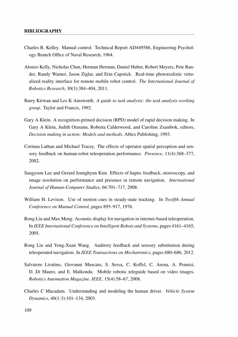
BIBLIOGRAPHY
Charles R. Kelley. Manual control. Technical Report AD449586, Engineering Psychol-ogy Branch Office of Naval Research, 1964.
Alonzo Kelly, Nicholas Chan, Herman Herman, Daniel Huber, Robert Meyers, Pete Ran-der, Randy Warner, Jason Ziglar, and Erin Capstick. Real-time photorealistic virtu-alized reality interface for remote mobile robot control. The International Journal of
Robotics Research, 30(3):384–404, 2011.
Barry Kirwan and Les K Ainsworth. A guide to task analysis: the task analysis working
group. Taylor and Francis, 1992.
Gary A Klein. A recognition-primed decision (RPD) model of rapid decision making. InGary A Klein, Judith Orasanu, Roberta Calderwood, and Caroline Zsambok, editors,Decision making in action: Models and methods. Ablex Publishing, 1993.
Corinna Lathan and Michael Tracey. The effects of operator spatial perception and sen-sory feedback on human-robot teleoperation performance. Presence, 11(4):368–377,2002.
Sangyoon Lee and Gerard Jounghyun Kim. Effects of haptic feedback, stereoscopy, andimage resolution on performance and presence in remote navigation. International
Journal of Human-Computer Studies, 66:701–717, 2008.
William H. Levison. Use of motion cues in steady-state tracking. In Twelfth Annual
Conference on Manual Control, pages 895–917, 1976.
Rong Liu and Max Meng. Acoustic display for navigation in internet-based teleoperation.In IEEE International Conference on Intelligent Robots and Systems, pages 4161–4165,2005.
Rong Liu and Yong-Xuan Wang. Auditory feedback and sensory substitution duringteleoperated navigation. In IEEE Transactions on Mechatronics, pages 680–686, 2012.
Salvatore Livatino, Giovanni Muscato, S. Sessa, C. Koffel, C. Arena, A. Pennisi,D. Di Mauro, and E. Malkondu. Mobile robotic teleguide based on video images.Robotics Automation Magazine, IEEE, 15(4):58–67, 2008.
Charles C Macadam. Understanding and modeling the human driver. Vehicle System
Dynamics, 40(1-3):101–134, 2003.
109
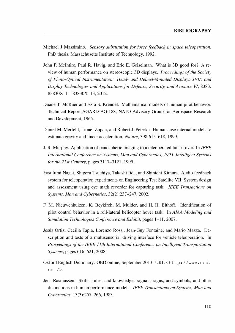
BIBLIOGRAPHY
Michael J Massimino. Sensory substitution for force feedback in space teleoperation.PhD thesis, Massachusetts Institute of Technology, 1992.
John P. McIntire, Paul R. Havig, and Eric E. Geiselman. What is 3D good for? A re-view of human performance on stereoscopic 3D displays. Proceedings of the Society
of Photo-Optical Instrumentation: Head- and Helmet-Mounted Displays XVII; and
Display Technologies and Applications for Defense, Security, and Avionics VI, 8383:83830X–1 – 83830X–13, 2012.
Duane T. McRuer and Ezra S. Krendel. Mathematical models of human pilot behavior.Technical Report AGARD-AG-188, NATO Advisory Group for Aerospace Researchand Development, 1965.
Daniel M. Merfeld, Lionel Zupan, and Robert J. Peterka. Humans use internal models toestimate gravity and linear acceleration. Nature, 398:615–618, 1999.
J. R. Murphy. Application of panospheric imaging to a teleoperated lunar rover. In IEEE
International Conference on Systems, Man and Cybernetics, 1995. Intelligent Systems
for the 21st Century, pages 3117–3121, 1995.
Yasufumi Nagai, Shigeru Tsuchiya, Takashi Iida, and Shinichi Kimura. Audio feedbacksystem for teleoperation experiments on Engineering Test Satellite VII: System designand assessment using eye mark recorder for capturing task. IEEE Transactions on
Systems, Man and Cybernetics, 32(2):237–247, 2002.
F. M. Nieuwenhuizen, K. Beykirch, M. Mulder, and H. H. Blthoff. Identification ofpilot control behavior in a roll-lateral helicopter hover task. In AIAA Modeling and
Simulation Technologies Conference and Exhibit, pages 1–11, 2007.
Jesus Ortiz, Cecilia Tapia, Lorenzo Rossi, Jean-Guy Fontaine, and Mario Mazza. De-scription and tests of a multisensorial driving interface for vehicle teleoperation. InProceedings of the IEEE 11th International Conference on Intelligent Transportation
Systems, pages 616–621, 2008.
Oxford English Dictionary. OED online, September 2013. URL <http://www.oed.
com/>.
Jens Rasmussen. Skills, rules, and knowledge: signals, signs, and symbols, and otherdistinctions in human performance models. IEEE Transactions on Systems, Man and
Cybernetics, 13(3):257–266, 1983.
110
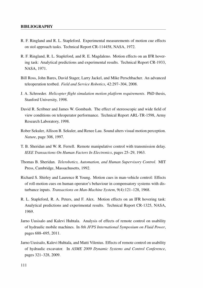
BIBLIOGRAPHY
R. F. Ringland and R. L. Stapleford. Experimental measurements of motion cue effectson stol approach tasks. Technical Report CR-114458, NASA, 1972.
R. F. Ringland, R. L. Stapleford, and R. E. Magdaleno. Motion effects on an IFR hover-ing task: Analytical predictions and experimental results. Technical Report CR-1933,NASA, 1971.
Bill Ross, John Bares, David Stager, Larry Jackel, and Mike Perschbacher. An advancedteleoperation testbed. Field and Service Robotics, 42:297–304, 2008.
J. A. Schroeder. Helicopter flight simulation motion platform requirements. PhD thesis,Stanford University, 1998.
David R. Scribner and James W. Gombash. The effect of stereoscopic and wide field ofview conditions on teleoperator performance. Technical Report ARL-TR-1598, ArmyResearch Laboratory, 1998.
Rober Sekuler, Allison B. Sekuler, and Renee Lau. Sound alters visual motion perception.Nature, page 308, 1997.
T. B. Sheridan and W. R. Ferrell. Remote manipulative control with transmission delay.IEEE Transactions On Human Factors In Electronics, pages 25–29, 1963.
Thomas B. Sheridan. Telerobotics, Automation, and Human Supervisory Control. MITPress, Cambridge, Massachusetts, 1992.
Richard S. Shirley and Laurence R Young. Motion cues in man-vehicle control: Effectsof roll-motion cues on human operator’s behaviour in compensatory systems with dis-turbance inputs. Transactions on Man-Machine System, 9(4):121–128, 1968.
R. L. Stapleford, R. A. Peters, and F. Alex. Motion effects on an IFR hovering task:Analytical predictions and experimental results. Technical Report CR-1325, NASA,1969.
Jarno Uusisalo and Kalevi Huhtala. Analysis of effects of remote control on usabilityof hydraulic mobile machines. In 8th JFPS International Symposium on Fluid Power,pages 688–695, 2011.
Jarno Uusisalo, Kalevi Huhtala, and Matti Vilenius. Effects of remote control on usabilityof hydraulic excavator. In ASME 2009 Dynamic Systems and Control Conference,pages 321–328, 2009.
111
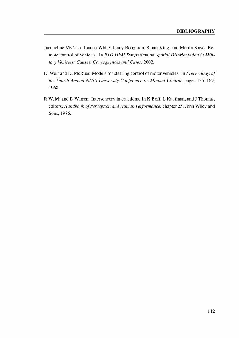
BIBLIOGRAPHY
Jacqueline Viveash, Joanna White, Jenny Boughton, Stuart King, and Martin Kaye. Re-mote control of vehicles. In RTO HFM Symposium on Spatial Disorientation in Mili-
tary Vehicles: Causes, Consequences and Cures, 2002.
D. Weir and D. McRuer. Models for steering control of motor vehicles. In Proceedings of
the Fourth Annual NASA-University Conference on Manual Control, pages 135–169,1968.
R Welch and D Warren. Intersencory interactions. In K Boff, L Kaufman, and J Thomas,editors, Handbook of Perception and Human Performance, chapter 25. John Wiley andSons, 1986.
112

APPENDIX A
Experimental Record
The following tables contain the completion times recorded in each experimental run.
113
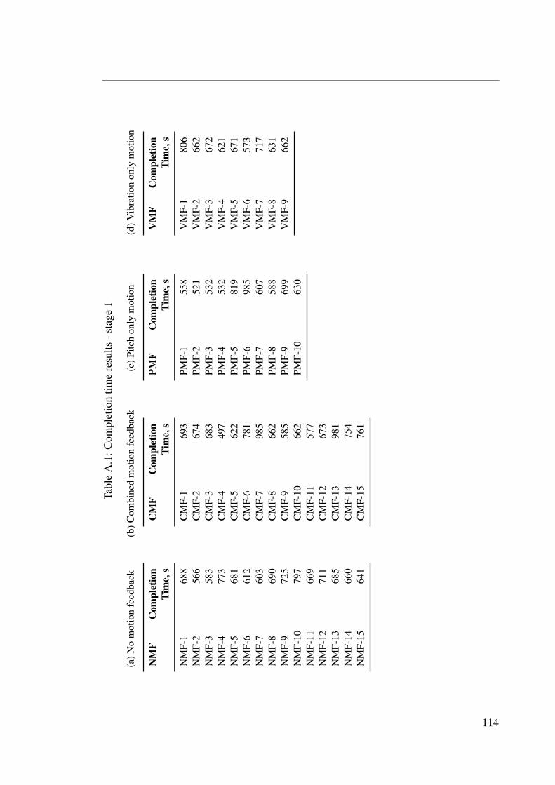
Tabl
eA
.1:C
ompl
etio
ntim
ere
sults
-sta
ge1
(a)N
om
otio
nfe
edba
ck
NM
FC
ompl
etio
nTi
me,
s
NM
F-1
688
NM
F-2
566
NM
F-3
583
NM
F-4
773
NM
F-5
681
NM
F-6
612
NM
F-7
603
NM
F-8
690
NM
F-9
725
NM
F-10
797
NM
F-11
669
NM
F-12
711
NM
F-13
685
NM
F-14
660
NM
F-15
641
(b)C
ombi
ned
mot
ion
feed
back
CM
FC
ompl
etio
nTi
me,
s
CM
F-1
693
CM
F-2
674
CM
F-3
683
CM
F-4
497
CM
F-5
622
CM
F-6
781
CM
F-7
985
CM
F-8
662
CM
F-9
585
CM
F-10
662
CM
F-11
577
CM
F-12
673
CM
F-13
981
CM
F-14
754
CM
F-15
761
(c)P
itch
only
mot
ion
PMF
Com
plet
ion
Tim
e,s
PMF-
155
8PM
F-2
521
PMF-
353
2PM
F-4
532
PMF-
581
9PM
F-6
985
PMF-
760
7PM
F-8
588
PMF-
969
9PM
F-10
630
(d)V
ibra
tion
only
mot
ion
VM
FC
ompl
etio
nTi
me,
s
VM
F-1
806
VM
F-2
662
VM
F-3
672
VM
F-4
621
VM
F-5
671
VM
F-6
573
VM
F-7
717
VM
F-8
631
VM
F-9
662
114
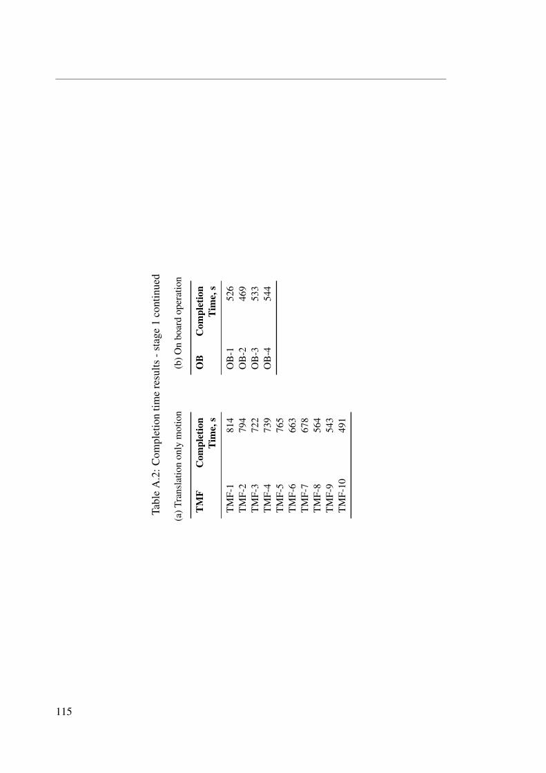
Tabl
eA
.2:C
ompl
etio
ntim
ere
sults
-sta
ge1
cont
inue
d
(a)T
rans
latio
non
lym
otio
n
TM
FC
ompl
etio
nTi
me,
s
TM
F-1
814
TM
F-2
794
TM
F-3
722
TM
F-4
739
TM
F-5
765
TM
F-6
663
TM
F-7
678
TM
F-8
564
TM
F-9
543
TM
F-10
491
(b)O
nbo
ard
oper
atio
n
OB
Com
plet
ion
Tim
e,s
OB
-152
6O
B-2
469
OB
-353
3O
B-4
544
115
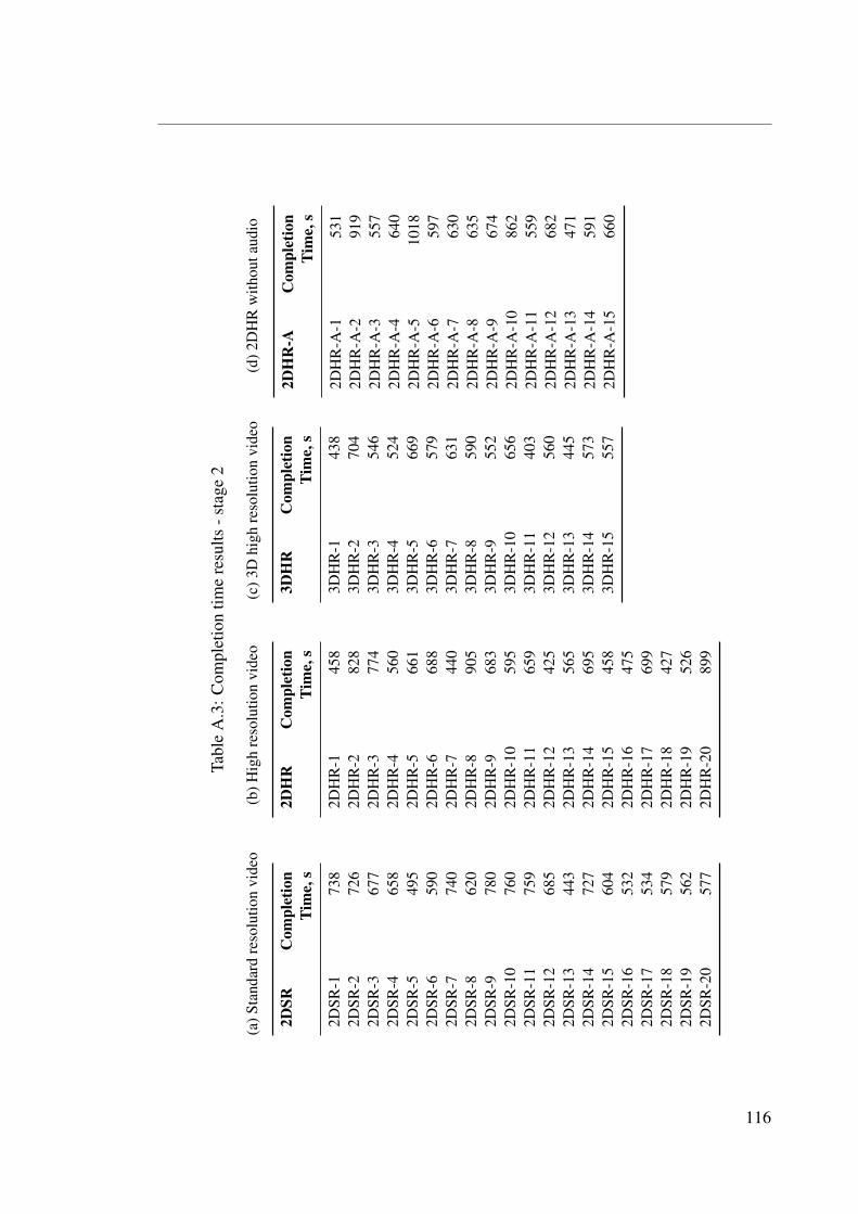
Tabl
eA
.3:C
ompl
etio
ntim
ere
sults
-sta
ge2
(a)S
tand
ard
reso
lutio
nvi
deo
2DSR
Com
plet
ion
Tim
e,s
2DSR
-173
82D
SR-2
726
2DSR
-367
72D
SR-4
658
2DSR
-549
52D
SR-6
590
2DSR
-774
02D
SR-8
620
2DSR
-978
02D
SR-1
076
02D
SR-1
175
92D
SR-1
268
52D
SR-1
344
32D
SR-1
472
72D
SR-1
560
42D
SR-1
653
22D
SR-1
753
42D
SR-1
857
92D
SR-1
956
22D
SR-2
057
7
(b)H
igh
reso
lutio
nvi
deo
2DH
RC
ompl
etio
nTi
me,
s
2DH
R-1
458
2DH
R-2
828
2DH
R-3
774
2DH
R-4
560
2DH
R-5
661
2DH
R-6
688
2DH
R-7
440
2DH
R-8
905
2DH
R-9
683
2DH
R-1
059
52D
HR
-11
659
2DH
R-1
242
52D
HR
-13
565
2DH
R-1
469
52D
HR
-15
458
2DH
R-1
647
52D
HR
-17
699
2DH
R-1
842
72D
HR
-19
526
2DH
R-2
089
9
(c)3
Dhi
ghre
solu
tion
vide
o
3DH
RC
ompl
etio
nTi
me,
s
3DH
R-1
438
3DH
R-2
704
3DH
R-3
546
3DH
R-4
524
3DH
R-5
669
3DH
R-6
579
3DH
R-7
631
3DH
R-8
590
3DH
R-9
552
3DH
R-1
065
63D
HR
-11
403
3DH
R-1
256
03D
HR
-13
445
3DH
R-1
457
33D
HR
-15
557
(d)2
DH
Rw
ithou
taud
io
2DH
R-A
Com
plet
ion
Tim
e,s
2DH
R-A
-153
12D
HR
-A-2
919
2DH
R-A
-355
72D
HR
-A-4
640
2DH
R-A
-510
182D
HR
-A-6
597
2DH
R-A
-763
02D
HR
-A-8
635
2DH
R-A
-967
42D
HR
-A-1
086
22D
HR
-A-1
155
92D
HR
-A-1
268
22D
HR
-A-1
347
12D
HR
-A-1
459
12D
HR
-A-1
566
0
116
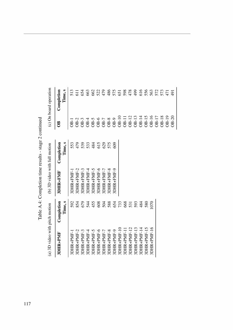
Tabl
eA
.4:C
ompl
etio
ntim
ere
sults
-sta
ge2
cont
inue
d
(a)3
Dvi
deo
with
pitc
hm
otio
n
3DH
R+P
MF
Com
plet
ion
Tim
e,s
3DH
R+P
MF-
159
23D
HR
+PM
F-2
854
3DH
R+P
MF-
367
93D
HR
+PM
F-4
544
3DH
R+P
MF-
545
53D
HR
+PM
F-6
608
3DH
R+P
MF-
750
43D
HR
+PM
F-8
588
3DH
R+P
MF-
965
43D
HR
+PM
F-10
733
3DH
R+P
MF-
1166
83D
HR
+PM
F-12
531
3DH
R+P
MF-
1359
33D
HR
+PM
F-14
484
3DH
R+P
MF-
1558
03D
HR
+PM
F-16
1070
(b)3
Dvi
deo
with
full
mot
ion
3DH
R+F
MF
Com
plet
ion
Tim
e,s
3DH
R+F
MF-
155
33D
HR
+FM
F-2
479
3DH
R+F
MF-
353
93D
HR
+FM
F-4
533
3DH
R+F
MF-
548
43D
HR
+FM
F-6
615
3DH
R+F
MF-
762
93D
HR
+FM
F-8
575
3DH
R+F
MF-
960
9
(c)O
nbo
ard
oper
atio
n
OB
Com
plet
ion
Tim
e,s
OB
-151
3O
B-2
611
OB
-365
4O
B-4
663
OB
-566
2O
B-6
522
OB
-747
9O
B-8
486
OB
-957
5O
B-1
065
1O
B-1
159
8O
B-1
247
8O
B-1
349
9O
B-1
461
6O
B-1
555
6O
B-1
656
3O
B-1
757
2O
B-1
857
3O
B-1
947
1O
B-2
049
1
117