Embed Size (px)
Citation preview
1
Johnson Space Center Overview
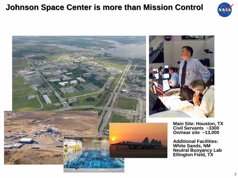
Johnson Space Center is more than Mission Control
Two mode Hybrid
Chrysler Technology Center Wind Tunnel
Main Site: Houston, TXCivil Servants ~3300On/near site ~13,000
Additional Facilities:White Sands, NMNeutral Buoyancy LabEllington Field, TX
2
3
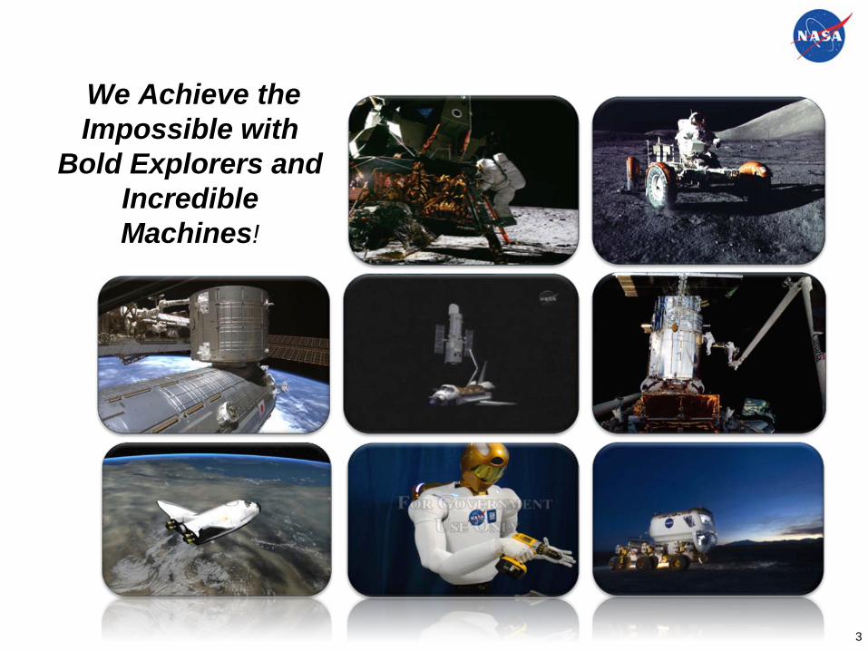
We Achieve the Impossible with
Bold Explorers and Incredible Machines!
3
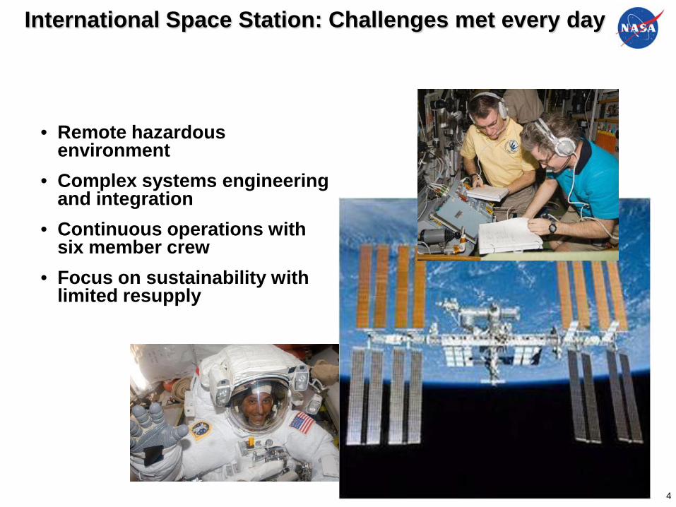
International Space Station: Challenges met every day
• Remote hazardous environment
• Complex systems engineering and integration
• Continuous operations with six member crew
• Focus on sustainability with limited resupply
4
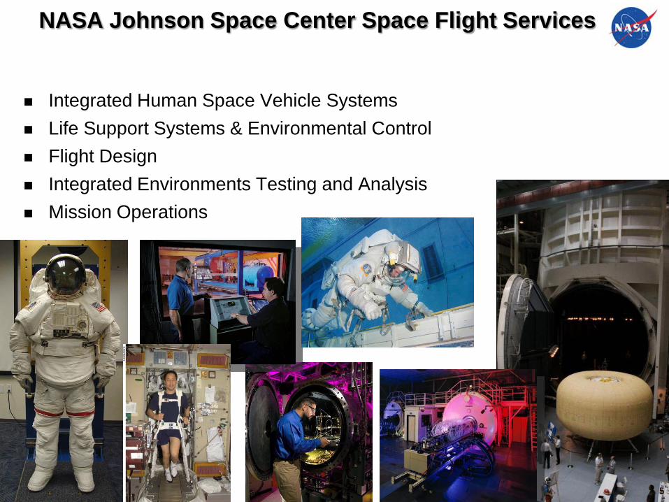
NASA Johnson Space Center Space Flight Services
Integrated Human Space Vehicle Systems Life Support Systems & Environmental Control Flight Design Integrated Environments Testing and Analysis Mission Operations
5

We engage our Program partners by providing
Technical Expertise
Analysis & Test Support
High Fidelity Simulation& Modeling
In-house Development
The outcome we strive to achieve is that partners embrace us as an integral partner who fulfills our commitments and proactively brings credible
solutions forward while maintaining a work environment that emphasizes continual learning and development
6
Program Partnerships
Technology Maturation
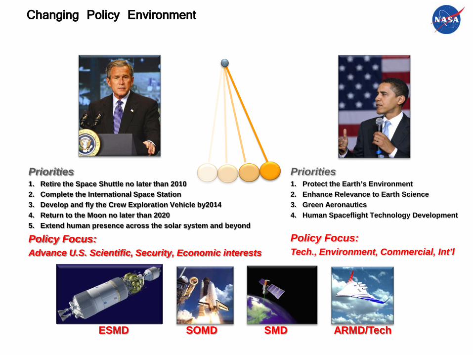
Priorities1. Retire the Space Shuttle no later than 20102. Complete the International Space Station3. Develop and fly the Crew Exploration Vehicle by20144. Return to the Moon no later than 20205. Extend human presence across the solar system and beyond
Policy Focus:Advance U.S. Scientific, Security, Economic interests
ESMD SOMD SMD ARMD/Tech
Priorities1. Protect the Earth’s Environment2. Enhance Relevance to Earth Science3. Green Aeronautics4. Human Spaceflight Technology Development
Policy Focus: Tech., Environment, Commercial, Int’l
Changing Policy Environment
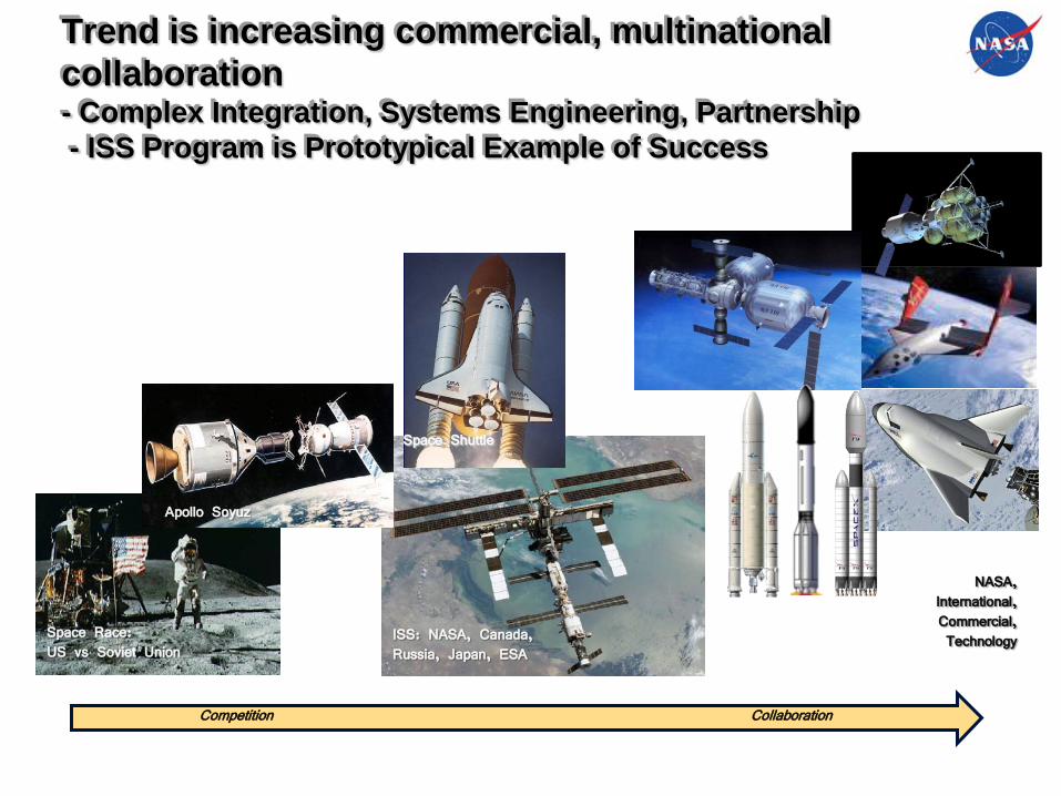
ISS: NASA, Canada, Russia, Japan, ESA
NASA, International,Commercial,TechnologySpace Race:
US vs Soviet Union
Apollo Soyuz
Space Shuttle
Trend is increasing commercial, multinational collaboration- Complex Integration, Systems Engineering, Partnership- ISS Program is Prototypical Example of Success
Competition Collaboration
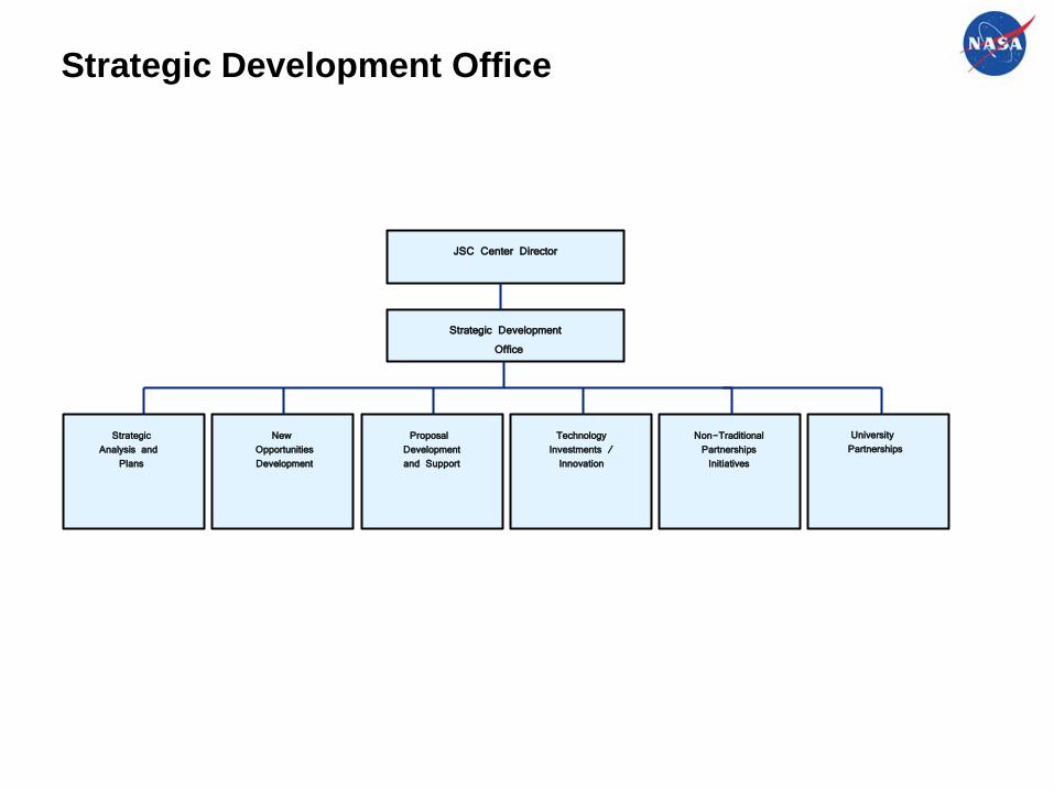
Strategic Development Office
Strategic Development
Office
StrategicAnalysis and
Plans
TechnologyInvestments /Innovation
New OpportunitiesDevelopment
Non-TraditionalPartnershipsInitiatives
Proposal Developmentand Support
University Partnerships
JSC Center Director

NASA SMD, Robotic Precursors , Observatories
Comm. Space
NASA Human Exploration
Aero
0 2 4 6 8 10 12 14 16 18 20 22 24 26
Distance – KM*10^
Exploration Domain Evolution
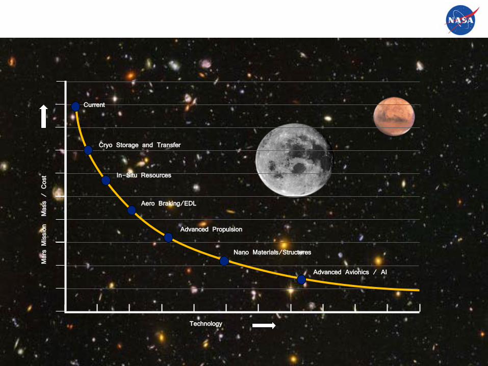
Mars Mission Mass / Cost
Technology
Current
In-Situ Resources
Aero Braking/EDL
Advanced Propulsion
Cryo Storage and Transfer
Nano Materials/Structures
Advanced Avionics / AI
Advanced Technology Can Reduce Cost of Spaceflight

Machine vs. Biological Intelligence Evolution
Humans
PrimitiveAnimals
Reptiles
4.2 4.3 4.4 4.5
Equivalent Biological Evolution Timescale – Billion years
Mammals
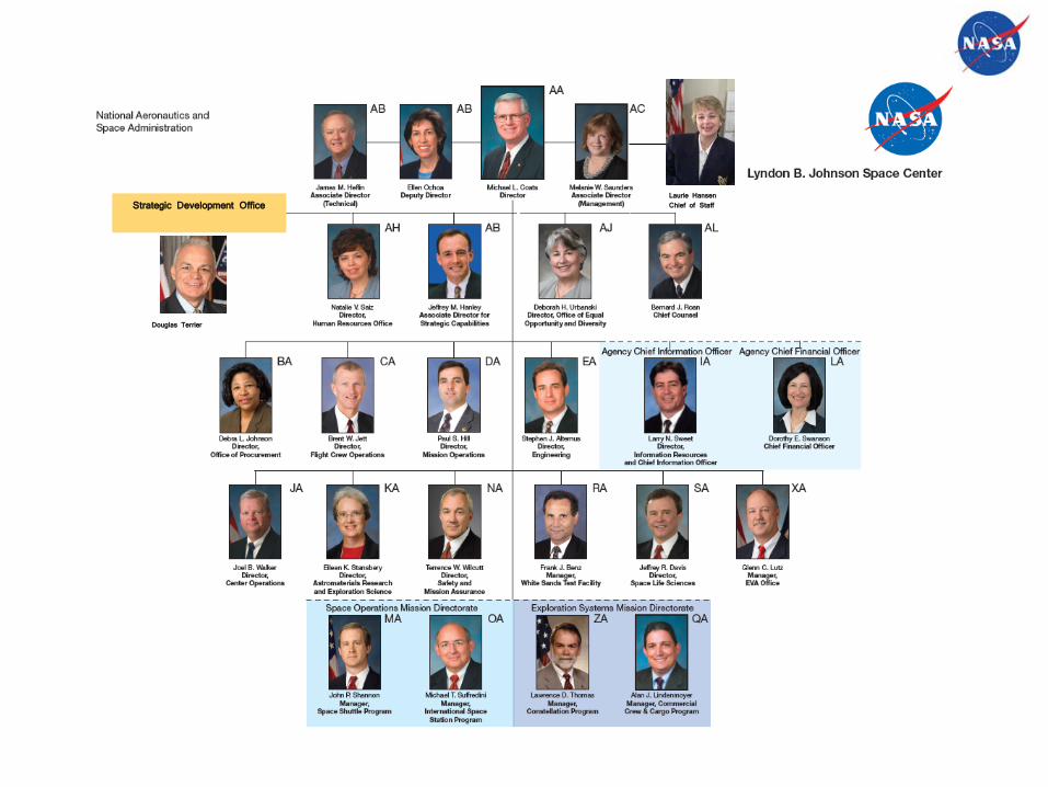
Strategic Development OfficeLaurie HansenChief of Staff
Douglas Terrier

14
15
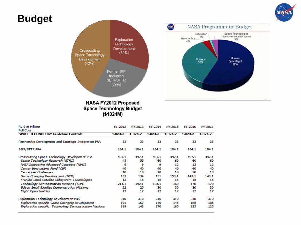
Budget
1
Technology Development AreasTammy Gafka, James Smith, Omar HatamlehNASA/Johnson Space CenterHouston, Texas
Collaborations with Airbus (Toulouse, France / Hamburg, Germany)April 2011 1
2
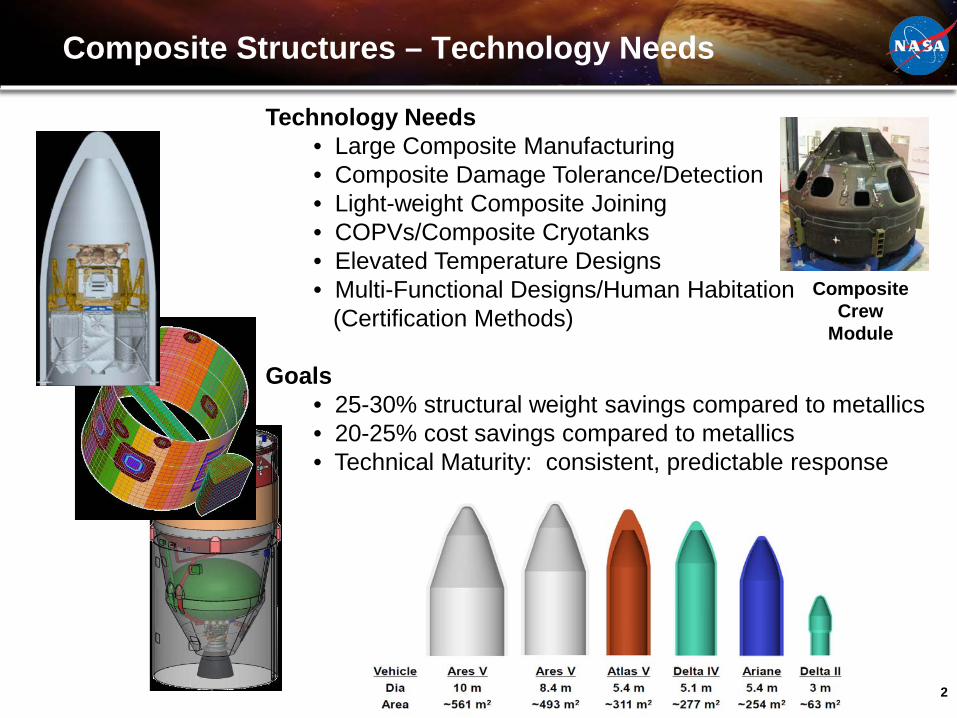
Composite Structures – Technology Needs
Technology Needs• Large Composite Manufacturing• Composite Damage Tolerance/Detection• Light-weight Composite Joining• COPVs/Composite Cryotanks• Elevated Temperature Designs• Multi-Functional Designs/Human Habitation
(Certification Methods)
Goals• 25-30% structural weight savings compared to metallics• 20-25% cost savings compared to metallics• Technical Maturity: consistent, predictable response
CompositeCrew
Module

3
Composite Structures – Large Structure Manufacturing
3
Automated FabricationStructural Concepts
Out-of-Autoclave/Out-Time Studies
4
2/13/2009
4
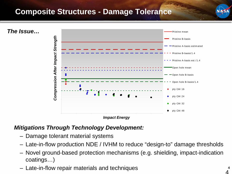
Composite Structures - Damage Tolerance
Pristine mean
Pristine B-basis
Pristine A-basis estimated
Pristine B-basis/1.4
Pristine A-basis est./1.4
Open hole mean
Open hole B-basis
Open hole B-basis/1.4
ply CAI 16
ply CAI 24
ply CAI 32
ply CAI 48
Impact Energy
Com
pres
sion
Afte
r Im
pact
Str
engt
h
Mitigations Through Technology Development:– Damage tolerant material systems– Late-in-flow production NDE / IVHM to reduce “design-to” damage thresholds– Novel ground-based protection mechanisms (e.g. shielding, impact-indication
coatings…)– Late-in-flow repair materials and techniques
The Issue…
5
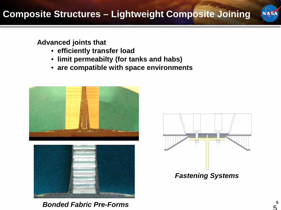
Composite Structures – Lightweight Composite Joining
2/13/2009
5
Fastening Systems
Bonded Fabric Pre-Forms
Advanced joints that• efficiently transfer load• limit permeabilty (for tanks and habs)• are compatible with space environments

6
Composite Structures – Cryotanks
6
Technical Challenges• Hydrogen Permeability• Immature Out-of-Autoclave Material Systems• Manufacturing and NDE Scale-Up• Damage Tolerance• Design Allowables at Representative Environments• Integrated w/ Structural Elements• Verification/Certification
Microcosm Tank
X-34 Tank

7
Composite Structures - COPV
7
Composite Failure Concerns
• Damage propagation from impactsMitigated by Damage Control Plan
• Manufacturing variabilityMitigated by qualification tests which include burst tests after thermal and pressure cycle tests
• Stress rupture (creep-like) failureCatastrophic failure after a given time at stress levelsMitigated by this proposed phased test approach
ISS N2 Tank
SAFER Tank
AMSTank
Subscale Vessel Test Program

8
Composite Structures – High Temperature Systems
8
High temperature (500+ deg F) material systems (composites, core, adhesives) with controlled impact energy absorption needed for re-entry/landing vehicle heat shields
Orion Heatshield
ISS Downmass Capsule

9
Composite Structures - Multi-Functional Designs
9
JSC Composite Structure Roadmap
10
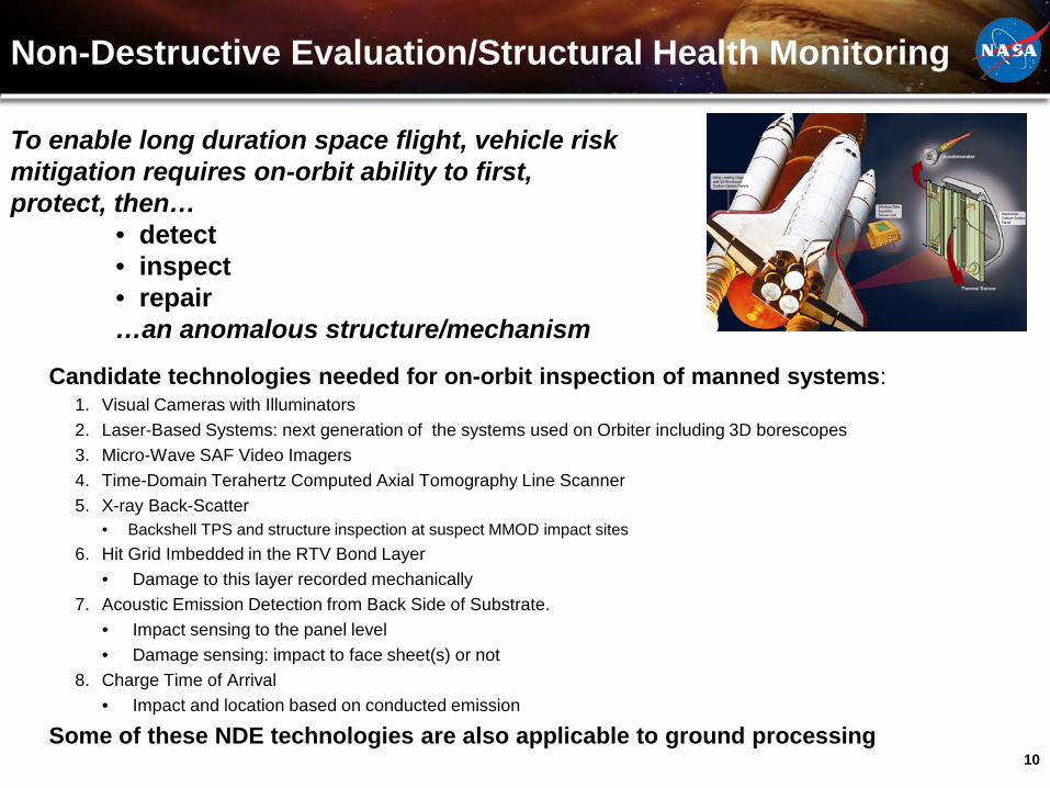
Non-Destructive Evaluation/Structural Health Monitoring
Candidate technologies needed for on-orbit inspection of manned systems:1. Visual Cameras with Illuminators 2. Laser-Based Systems: next generation of the systems used on Orbiter including 3D borescopes3. Micro-Wave SAF Video Imagers4. Time-Domain Terahertz Computed Axial Tomography Line Scanner5. X-ray Back-Scatter
• Backshell TPS and structure inspection at suspect MMOD impact sites6. Hit Grid Imbedded in the RTV Bond Layer
• Damage to this layer recorded mechanically7. Acoustic Emission Detection from Back Side of Substrate.
• Impact sensing to the panel level• Damage sensing: impact to face sheet(s) or not
8. Charge Time of Arrival • Impact and location based on conducted emission
Some of these NDE technologies are also applicable to ground processing
To enable long duration space flight, vehicle risk mitigation requires on-orbit ability to first, protect, then…
• detect• inspect• repair…an anomalous structure/mechanism
11
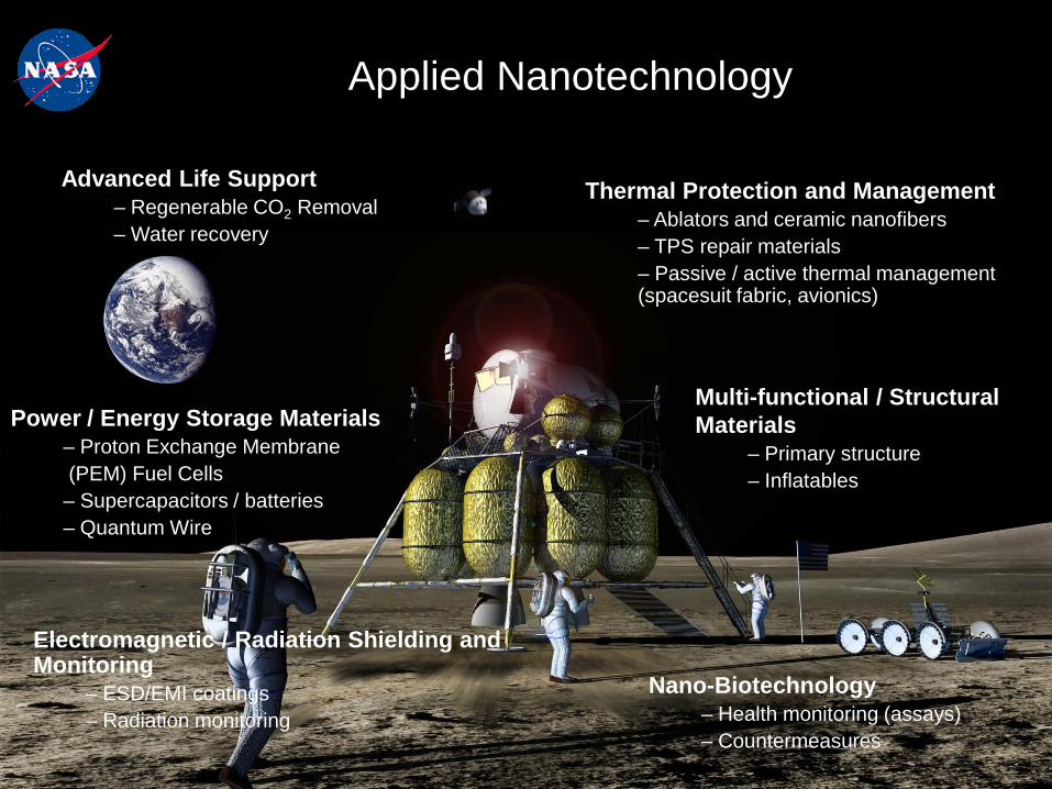
Applied Nanotechnology
Power / Energy Storage Materials– Proton Exchange Membrane (PEM) Fuel Cells– Supercapacitors / batteries– Quantum Wire
Advanced Life Support– Regenerable CO2 Removal– Water recovery
Thermal Protection and Management– Ablators and ceramic nanofibers– TPS repair materials– Passive / active thermal management (spacesuit fabric, avionics)
Electromagnetic / Radiation Shielding and Monitoring
– ESD/EMI coatings– Radiation monitoring
Multi-functional / Structural Materials
– Primary structure– Inflatables
Nano-Biotechnology– Health monitoring (assays)– Countermeasures
12
Nanotechnology
12
The Nanotechnology Group’s Current Projects:• Self healing multifunctional Composites• Gas Absorption: MOF Nanomaterials• Solar Cells – Band Gap Engineered High Efficiency Solar Cells• Aluminum/Nanocomposite Materials – Aluminum having the strength of steel yet the weight of aluminum.
Our Main Focus Areas:Energy: this area includes energy storage, energy generation, and energy systemsEnvironmental Control and Life Support Systems: This area is primarily the systems required to ensure the astronauts health and survivability. It includes air systems, temperature control, food, waste, humidity control, space suites, life support systems, radiation protection, etc.Nanomaterials: This includes nanocomposites, Improved damage tolerance, structural health monitoring, self repair materials, multifunctional materials, lightning strike protection, coatings, and textiles/fabrics, seals, thermal materialsLife Sciences (nano-biotechnology): crew health, nanomedicine
Possible Areas of Collaboration:Nanocomposites: Nanotechnology offers self healing capabilities, lightning strike protection (multifunctional capabilities), and high structural strength. Gas/Energy Storage: We have interest in hydrogen, carbon dioxide, methane, and oxygen gas storage. This has applications for fuel storage for long duration space missions and terrestrial applications for sustainability efforts.Other Energy Storage: We also have interest in ultra capacitors, fly wheels and batteries.Energy Generation: Our interests include solar cells, fuel cells, piezoelectrics, and thermoelectric.Gas Separation: We are interested in areas to more efficiently separate gases for applications such as bioreactors.
13
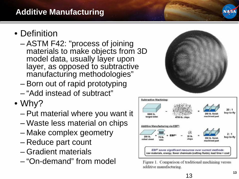
Additive Manufacturing
• Definition– ASTM F42: "process of joining
materials to make objects from 3D model data, usually layer upon layer, as opposed to subtractive manufacturing methodologies”
– Born out of rapid prototyping– “Add instead of subtract”
• Why?– Put material where you want it– Waste less material on chips– Make complex geometry– Reduce part count– Gradient materials– “On-demand” from model
13
14
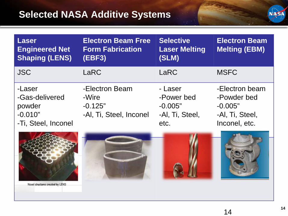
Selected NASA Additive Systems
Laser Engineered Net Shaping (LENS)
Electron Beam Free Form Fabrication (EBF3)
Selective Laser Melting (SLM)
Electron Beam Melting (EBM)
JSC LaRC LaRC MSFC
-Laser-Gas-delivered powder-0.010”-Ti, Steel, Inconel
-Electron Beam-Wire-0.125”-Al, Ti, Steel, Inconel
- Laser-Power bed-0.005”-Al, Ti, Steel, etc.
-Electron beam-Powder bed-0.005”-Al, Ti, Steel, Inconel, etc.
14
15
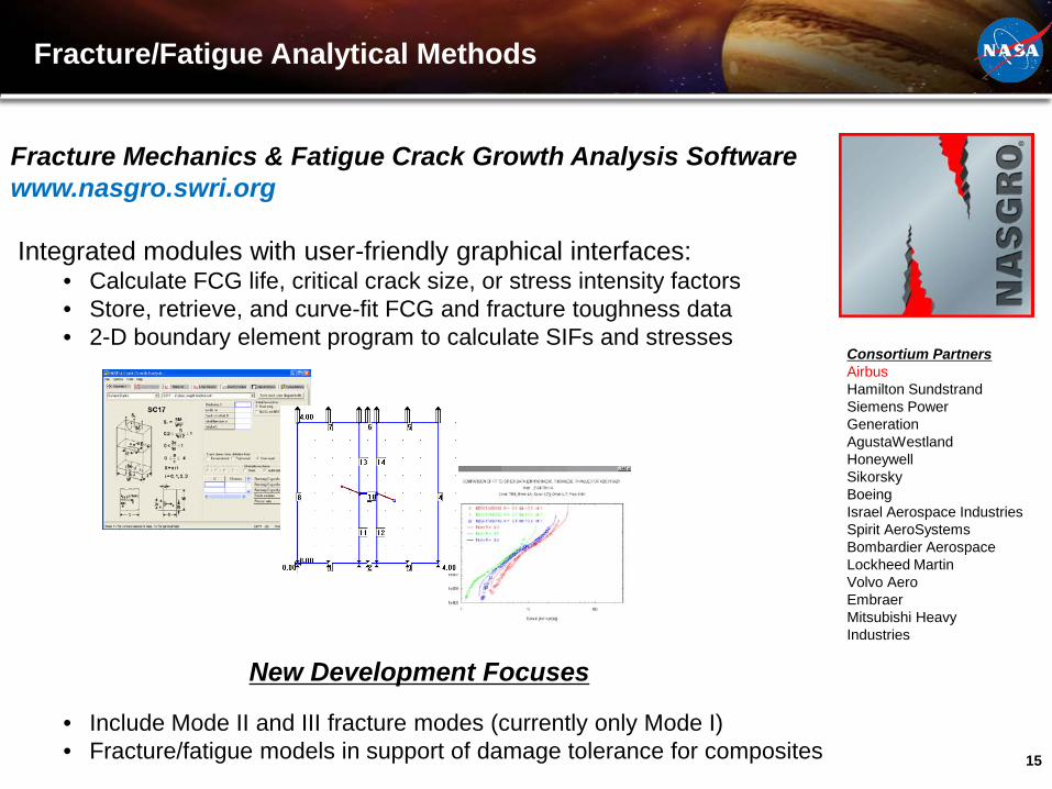
Fracture/Fatigue Analytical Methods
Consortium PartnersAirbus Hamilton Sundstrand Siemens Power Generation AgustaWestlandHoneywell Sikorsky Boeing Israel Aerospace Industries Spirit AeroSystemsBombardier Aerospace Lockheed Martin Volvo Aero EmbraerMitsubishi Heavy Industries
Fracture Mechanics & Fatigue Crack Growth Analysis Softwarewww.nasgro.swri.org
Integrated modules with user-friendly graphical interfaces: • Calculate FCG life, critical crack size, or stress intensity factors • Store, retrieve, and curve-fit FCG and fracture toughness data • 2-D boundary element program to calculate SIFs and stresses
New Development Focuses
• Include Mode II and III fracture modes (currently only Mode I)• Fracture/fatigue models in support of damage tolerance for composites
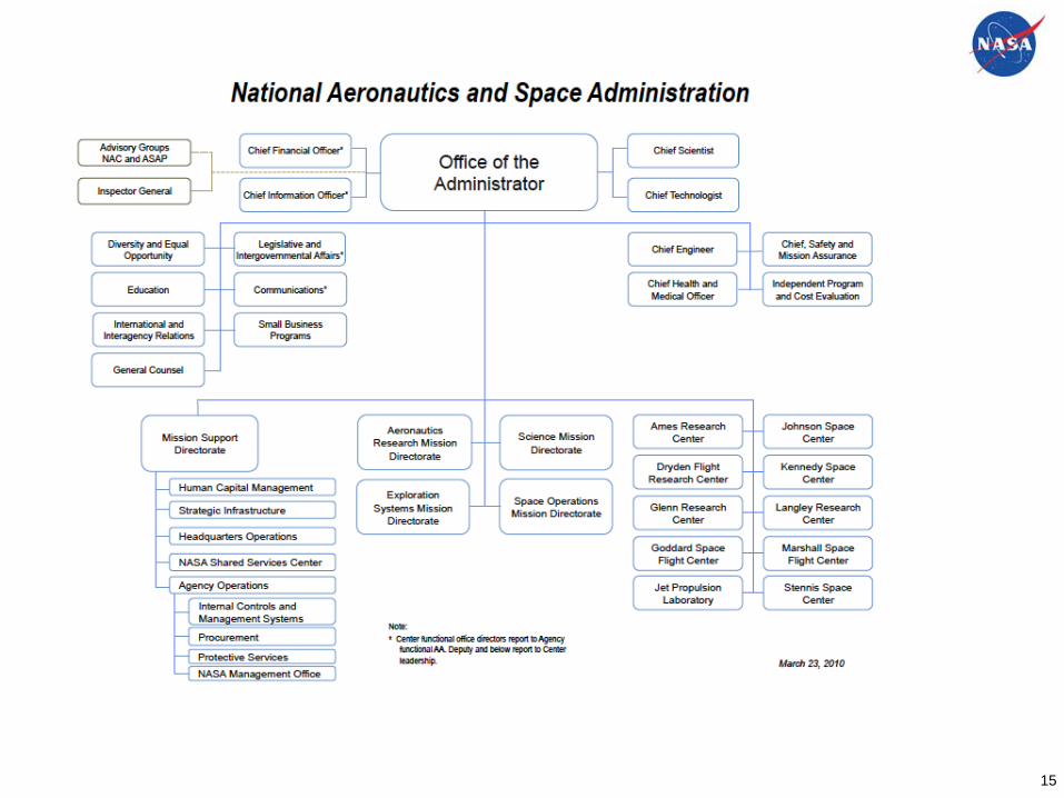
National Aeronautics and Space Administration
Space Technology Program, Office of Chief Technologist
Structural Analysis Capabilities Within NASA/JSCJames P. Smith, Ph.D.NASA/JSC/[email protected]
17
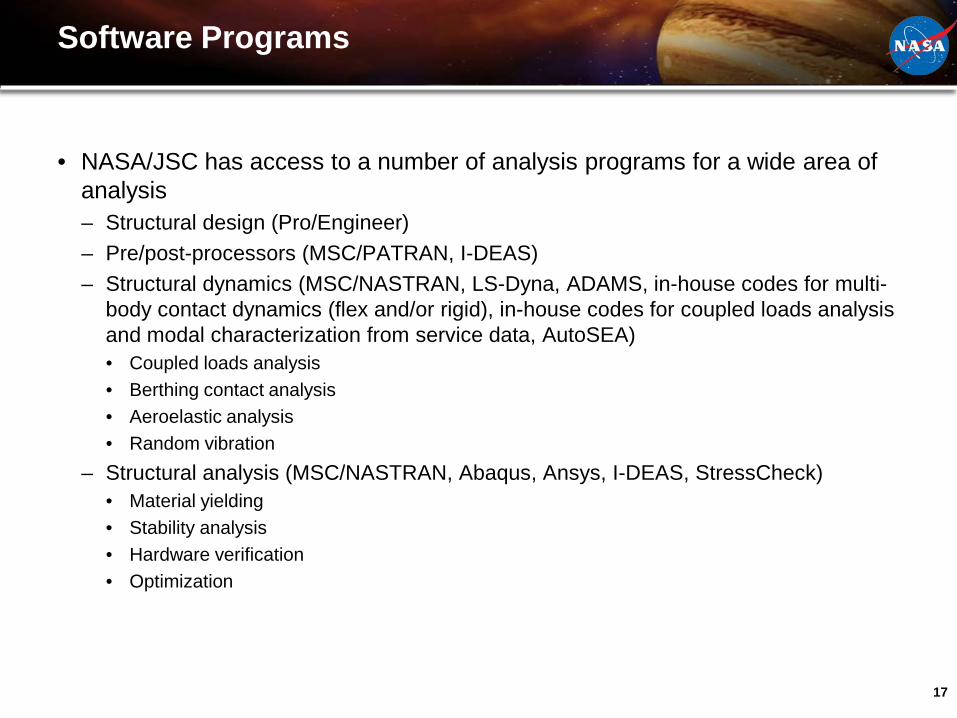
Software Programs
• NASA/JSC has access to a number of analysis programs for a wide area of analysis– Structural design (Pro/Engineer)– Pre/post-processors (MSC/PATRAN, I-DEAS)– Structural dynamics (MSC/NASTRAN, LS-Dyna, ADAMS, in-house codes for multi-
body contact dynamics (flex and/or rigid), in-house codes for coupled loads analysis and modal characterization from service data, AutoSEA)• Coupled loads analysis• Berthing contact analysis • Aeroelastic analysis• Random vibration
– Structural analysis (MSC/NASTRAN, Abaqus, Ansys, I-DEAS, StressCheck)• Material yielding• Stability analysis• Hardware verification• Optimization

18
Treadmill-2/COLBERT Anomaly
• Mis-use by the ISS crew of the COLBERT system caused a suspect condition of the structural integrity of the downstream joint
• Nonlinear material, geometric, and contact analysis performed to assess if there was reserve capacity in the bracket attach hardware
19
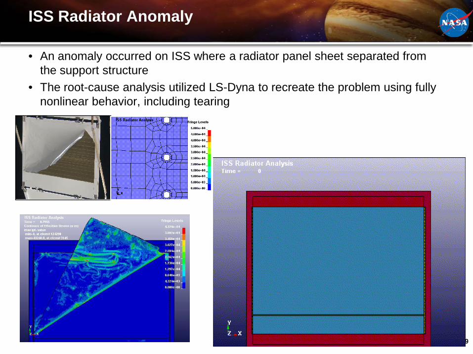
ISS Radiator Anomaly
• An anomaly occurred on ISS where a radiator panel sheet separated from the support structure
• The root-cause analysis utilized LS-Dyna to recreate the problem using fully nonlinear behavior, including tearing
20
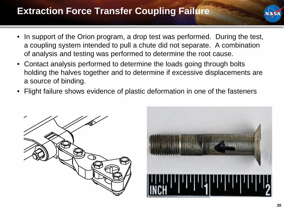
Extraction Force Transfer Coupling Failure
• In support of the Orion program, a drop test was performed. During the test, a coupling system intended to pull a chute did not separate. A combination of analysis and testing was performed to determine the root cause.
• Contact analysis performed to determine the loads going through bolts holding the halves together and to determine if excessive displacements are a source of binding.
• Flight failure shows evidence of plastic deformation in one of the fasteners
21
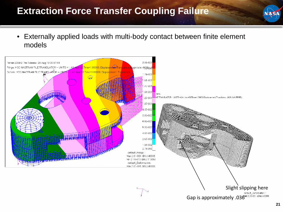
Extraction Force Transfer Coupling Failure
• Externally applied loads with multi-body contact between finite element models
Gap is approximately .036”
Slight slipping here
22
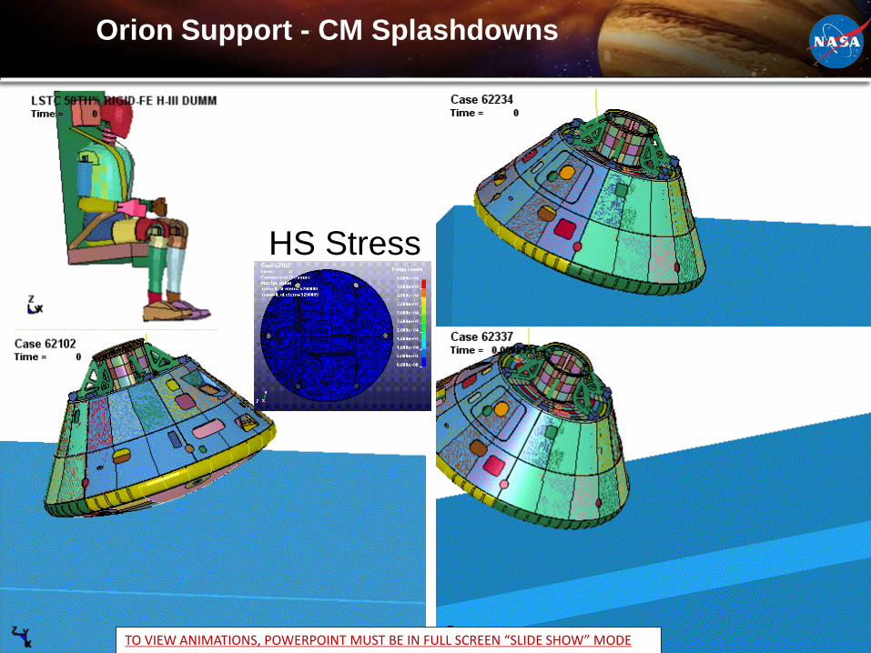
Orion Support - CM Splashdowns
HS Stress
TO VIEW ANIMATIONS, POWERPOINT MUST BE IN FULL SCREEN “SLIDE SHOW” MODE
National Aeronautics and Space Administration
Space Technology Program, Office of Chief Technologist
Friction Stir Welding and Laser PeeningOmar Hatamleh, Ph.D.NASA/JSC/[email protected]
24
Friction Stir Welding
• Friction Stir Welding (FSW) is a solid-state metal joining process producing high-strength, defect-free joints in metallic materials. The process employs a pin tool with a low rotational speed and applied pressure that "mechanically stirs" two parent materials together to produce a uniform weld.
• The process employs a pin tool with a low rotational speed and applied pressure that "mechanically stirs" two parent materials together to produce a uniform weld.
25
National Center for Advanced Manufacturing
• Partnership between NASA, the State of Louisiana, and the University of New Orleans
• NCAM combines education, research, and manufacturing to provide leadership in technology.
• Located in New Orleans, Louisiana at NASA's Michoud Assembly Facility (MAF), which is managed by Marshall Space Flight Center in Huntsville, Alabama
• NCAM has three machines for FSW called the Universal Weld Systems or UWS 1-3, in the order in which they were installed.
Source: http://www.ncamlp.org/about/about.html

26
FSW at JSC
• JSC equipment includes an MTS FSW Process Development System (PDS)• The PDS is a fully instrumented research system that is capable of
simultaneous force-controlled operation of three independent axes (X, Z, Pin)• The PDS can do research work and process development for the larger MTS
systems at the Michoud Assembly Facility which use the same weld head
Source: http://www.mts.com/en/TechnologyShowcase/FSW/Intelligent/index.asp

27
NCAM UWS#1 & UWS #2
Capacity• 16 ft. x 21.5 ft. x 10 ft. of linear
motion• 2 axis of gimbal motion of the
weld head• 30 ft. rotary table with one
rotational degree of freedom
Capacity• 40 ft. 10 in. X-Axis x 22 ft. 8 in. Y-Axis x
12 ft. 2 in. Z-Axis of linear motion• 2 axis of gimbal motion of the weld head• 22 ft. rotary table with one rotational
degree of freedom• 40 ft. x 20 ft. flat weld area with T-slots
http://www.ncamlp.org/technology/fsw-UWS2.htmlhttp://www.ncamlp.org/technology/fsw-UWS1.html
28
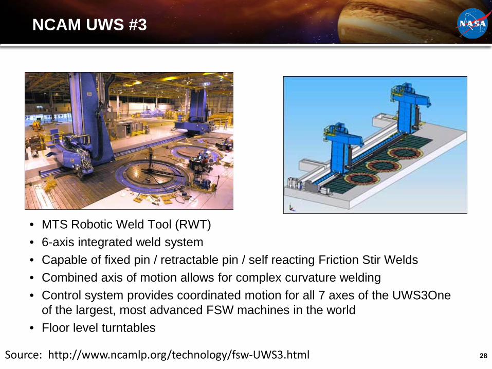
NCAM UWS #3
• MTS Robotic Weld Tool (RWT)• 6-axis integrated weld system• Capable of fixed pin / retractable pin / self reacting Friction Stir Welds• Combined axis of motion allows for complex curvature welding• Control system provides coordinated motion for all 7 axes of the UWS3One
of the largest, most advanced FSW machines in the world• Floor level turntables
Source: http://www.ncamlp.org/technology/fsw-UWS3.html
29
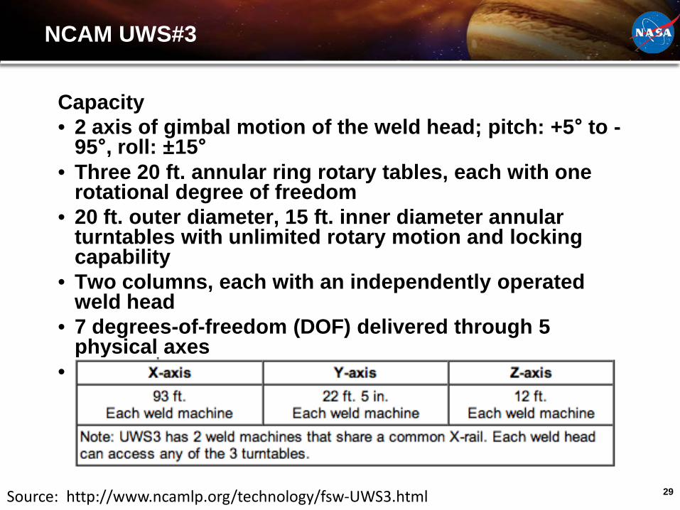
NCAM UWS#3
Capacity• 2 axis of gimbal motion of the weld head; pitch: +5° to -
95°, roll: ±15°• Three 20 ft. annular ring rotary tables, each with one
rotational degree of freedom• 20 ft. outer diameter, 15 ft. inner diameter annular
turntables with unlimited rotary motion and locking capability
• Two columns, each with an independently operated weld head
• 7 degrees-of-freedom (DOF) delivered through 5 physical axes
• Work envelopes shown in table below:
Source: http://www.ncamlp.org/technology/fsw-UWS3.html


![NASA JOHNSON SPACE CENTER ORAL HISTORY … · This interview is being conducted with Sunita Williams in Houston, ... Michael] Fincke, Sandy ... NASA JOHNSON SPACE CENTER ORAL HISTORY](https://img.pdfslide.net/doc/110x75/5b6c7a2d7f8b9aa32b8b8892/nasa-johnson-space-center-oral-history-this-interview-is-being-conducted-with.jpg)