Embed Size (px)
Citation preview

Joining Processes
and Equipment
ME305 Manufacturing Techniques Course Material, Adnan Menderes University
(Source: Serope Kalpakjian, Steven Schmid-Manufacturing, Engineering and Technology, 6e)
1

2

Joining Processes
Joining processes fall into three major categories;
• Welding,• Fusion Welding,
• Solid-state Welding,
• Brazing and Soldering.
• Adhesive Bonding,
• Mechanical Fastening
3

Joining Processes
• Fusion Welding is defined as the melting together and coalescing of materials by means of heat, usually supplied by chemical or electrical means; filler metals may or may not be used.
• Fusion welding is composed of
• Consumable- and non-consumable electrode arc welding and
• High-energy-beam welding processes.
• The Welded joint undergoes important metallurgical and physical changes, which, in turn, have a major effect on the properties and performance of the welded component or structure.
4

Joining Processes
• In solid-state welding, joining takes place without fusion; consequently, there is no liquid (molten) phase in the joint.
• The basic processes in this category are
Diffusion bonding,
Cold welding,
Ultrasonic welding,
Friction welding,
Resistance welding, and
Explosion welding.
5

Joining Processes
• Brazing uses filler metals and involves lower temperatures than welding.
• Soldering uses similar filler metals (solders) and involves even lower temperatures.
• Adhesive bonding has unique applications that require strength, sealing, thermal and electrical insulating, vibration damping, and resistance to corrosion between dissimilar metals.
6

Joining Processes
7

Joining Processes
Examples of joints that can be made through the various joining processes.
8

Fusion-Welding Processes
9

Fusion Welding
•Fusion welding is a generic term for welding processes that rely upon melting to join materials of similar compositions and melting points. – Wikipedia
• These processes include the oxyfuel-gas, arc, and high-energy-beam (laser-beam and electron-beam) welding processes, which haveimportant and unique applications in modern manufacturing.
10

Fusion Welding
11

Fusion Welding: Oxyfuel Gas Welding
• Oxyfuel-gas welding (OFW) is a general term used to describe any welding process that uses a fuel gas combined with oxygen to produce a flame.
• The most common gas-welding process uses acetylene; the process is known as oxyacetylene-gas welding (OAW) and is typically used for structural metal fabrication and repair work.
12

Fusion Welding: Oxyfuel Gas Welding
Three basic types of oxyacetylene flames used in oxyfuel–gas welding and cutting operations: (a) neutral flame; (b) oxidizing flame; and (c) carburizing, or reducing, flame. The gas mixture in (a) is basically equal volumes of oxygen and
acetylene. (d) The principle of the oxyfuel–gas welding process. 13

Fusion Welding: Oxyfuel Gas Welding
•Versatility: OFW can be used with most ferrous and nonferrous metals for almost any workpiece thickness.•Deep groove joints are made in multiple
passes. Cleaning the surface of each weld bead prior to depositing a second layer is important.•The equipment for oxyfuel-gas welding
consists basically of a welding torchconnected by hoses to high-pressure gas cylinders and equipped with pressure gages and regulators. 14

Fusion Welding: Oxyfuel Gas Welding
2𝐶𝑂 + 𝐻2 + 1,5𝑂2 → 2𝐶𝑂2 + 𝐻2𝑂 + 𝑯𝑬𝑨𝑻
𝐶2𝐻2 +𝑂2 → 2𝐶𝑂 + 𝐻2 +𝑯𝑬𝑨𝑻
The primary combustion process, which occurs in the inner core of the flame;
The secondary combustion process is;
*** The temperatures developed in the flame can reach 3300°C.15

Fusion Welding: Oxyfuel Gas Welding
• The low equipment cost is an attractive feature of oxyfuel-gas welding.
• Although it can be mechanized, this operation is essentially manual and, hence,slow.
• However, it has the advantages of being portable, versatile, and economical for simple and low-quantity work.
16

Fusion Welding: Oxyfuel Gas Welding
(a) General view,
(b) cross-section of a torch used in oxyacetylene welding. • The acetylene valve is
opened first; • the gas is lit with a spark
lighter or a pilot light. • Then the oxygen valve is
opened and the flame adjusted.
(c) Oxygen regulators usually are painted green and acetylene regulators red.
17

Fusion Welding: Pressure-Gas Welding
The welding of two components starts with the heating of the interface by means of a torch using (typically) an oxyacetylene-gas mixture. After the interface begins to melt, the torch is withdrawn.
18

Fusion Welding: Pressure-Gas Welding
A force is applied to press the two components togetherand is maintained until the interface solidifies. Note the
formation of a flash due to the upsetting of the joined ends of the two components. 19

Fusion Welding: Arc-Welding Processes
Nonconsumable Electrode
•The heat required is obtained fromelectrical energy.
•An AC or a DC power supply produces an arc between the tip of the electrode and the workpiece to be welded.
•The arc generates temperatures of about
30,000°C (in both consumable and nonconsumable processes).
20

Fusion Welding: Arc-Welding Processes
Nonconsumable Electrode•The electrode is typically a tungsten
electrode.•Because of the high temperatures involved,
an externally supplied shielding gas is necessary to prevent oxidation of the weld zone.•The selection of current levels depends on
such factors as the type of electrode, metals to be welded, and depth and width of the weld zone.
21

Fusion Welding: Arc-Welding Processes
22

Fusion Welding: Arc-Welding Processes
Nonconsumable Electrode
•Typically, direct current is used, and its polarity (the direction of current flow) is important.
• In straight polarity, (or direct-current electrode negative, DCEN), the workpiece is positive (anode), and the electrode is negative (cathode). DCEN generallyproduces welds that are narrow and deep.
23

Fusion Welding: Arc-Welding Processes
Nonconsumable Electrode
• In reverse polarity (or direct-current electrode positive DCEP), the workpiece is negative and the electrode is positive. Weld penetration is less, and the weld zone is shallower and wider. Hence, DCEP is preferred for sheet metals and for joints with very wide gaps.
24

Fusion Welding: Arc-Welding Processes
(a) DCEN current with straight polarity; (b) DCEPcurrent with reverse polarity; and (c) AC current.
In the AC current method, the arc pulsates rapidly. This method is suitable for welding thick sections and for using large-diameter electrodes at maximumcurrents.
25

Fusion Welding: Arc-Welding Processes
26

Fusion Welding: Arc-Welding Processes
Nonconsumable Electrode
Gas Tungsten-arc Welding (GTAW)
-Gaz Örtülü Ark Kaynağı-
•Formerly known as TIG (for “tungsten inert gas”) welding, the filler metal is supplied from a filler wire.
•Because the tungsten electrode is not consumed in this operation, a constant and stable arc gap is maintained at a constant current level.
27

Fusion Welding: Arc-Welding ProcessesNonconsumable Electrode
Gas Tungsten-arc Welding (GTAW)•Welding with GTAW may be done without
filler metals-for example, in the welding of close-fit joints.• Since not being consumed during the
process, tungsten electrode contamination by the molten metal can be a significant problem, particularly in critical applications, because it can cause discontinuities in the weld.
28

Fusion Welding: Arc-Welding ProcessesNonconsumable Electrode
Gas Tungsten-arc Welding (GTAW)•The GTAW process is used for a wide
variety of applications and metals, particularly aluminum, magnesium, titanium, and the refractory metals. • It is especially suitable for thin metals. •The cost of the inert gas makes this process
more expensive than SMAW (ShieldedMetal-Arc Welding) but provides welds of very high quality and surface finish.
29

Fusion Welding: Arc-Welding ProcessesNonconsumable Electrode
Plasma Arc Welding (PAW)•A plasma is an ionized hot gas composed of
nearly equal numbers of electrons and ions.•A concentrated plasma arc is produced and
directed towards the weld area. The arc isstable and reaches temperatures as high as 33,000°C.•The plasma arc is concentrated by forcing it
through a relatively small orifice.30

Fusion Welding: Arc-Welding Processes
31

Fusion Welding: Arc-Welding Processes
Nonconsumable Electrode
Plasma Arc Welding (PAW)
• In the transferred-arc method, the workpiece being welded is part of the electrical circuit. The arc transfers from the electrode to the workpiece hence the term transferred.
• In the nontransferred method, the arc occurs between the electrode and the nozzle, and the heat is carried to the workpiece by the plasmagas. This thermal-transfer mechanism is similar to that for an oxyfuel flame.
32

Fusion Welding: Arc-Welding Processes
Two types of plasma-arc welding processes: (a) transferred and (b) nontransferred; deep and narrow welds can be made
by these processes at high welding speeds.33

Fusion Welding: Arc-Welding ProcessesNonconsumable Electrode
Plasma Arc Welding (PAW)
Compared with other arc-welding processes,
• Plasma-arc welding has better arc stability,
• Less thermal distortion, and
• Higher energy concentration, permittingdeeper and narrower welds.
• In addition, higher welding speeds, from 120 to1000 mm/min, can be achieved.
• A variety of metals can be welded with part thicknesses generally less than 6 mm.
34

Fusion Welding: Arc-Welding Processes
Consumable Electrode
Shielded Metal-arc Welding (SMAW)
•One of the oldest, simplest, and most versatile joining processes.
•About 50% of all industrial and maintenance welding currently isperformed by this process.
35

Fusion Welding: Arc-Welding Processes
Shielded Metal-arc Welding• The electric arc is generated by touching the tip of a coated
electrode against the workpiece and withdrawing it quickly to a distance sufficient to maintain the arc.
• The heat generated melts a portion of the electrode tip, its coating, and the base metal in the immediate arc area.
• The electrode coating deoxidizes the weld area and provides a shielding gas to protect it from oxygen in the environment.36

Fusion Welding: Arc-Welding Processes
37

Fusion Welding: Arc-Welding Processes
Consumable Electrode
Shielded Metal-arc Welding
•For sheet-metal welding, DC is preferred because of the steady arc it produces.
•Power requirements generally are less than 10 kW.
•The process has the advantages of being relatively simple, versatile, and requiring a smaller variety of electrodes.
38

Fusion Welding: Arc-Welding Processes
Consumable Electrode
Shielded Metal-arc Welding
•The SMAW process commonly is used ingeneral construction, shipbuilding, pipelines, and maintenance work.
• SMAW is best suited for workpiece thicknesses of 3 to 19 mm, although this range can be extended easily by skilled operators using multiple-pass techniques.
39

Fusion Welding: Arc-Welding Processes
Consumable Electrode
Shielded Metal-arc Welding
• The multiple-pass approach requires that the slag be removed after each weld bead.
•Both labor costs and material costs are high.
40

Fusion Welding: Arc-Welding ProcessesConsumable Electrode
Submerged-arc Welding• The weld arc is shielded by a granular flux consisting of lime, silica,
manganese oxide, calcium fluoride, and other compounds.
41

Fusion Welding: Arc-Welding Processes
Consumable Electrode Submerged-arc Welding
• The thick layer of flux completely covers the molten metal. It prevents spatter and sparks and suppresses the intense ultraviolet radiation and fumes characteristic of the SMAW process. The flux also acts as a thermal insulator by promoting deep penetration of heat into the workpiece. 42

Fusion Welding: Arc-Welding Processes
43

Fusion Welding: Arc-Welding Processes
Consumable Electrode Submerged-arc Welding
• The unfused flux can be recovered, treated, and reused.
• SAW is automated and is used to weld a variety of carbon and alloy steel and stainless-steel sheets orplates at speeds as high as 5 m/min.
• The quality of the weld is very high with goodtoughness, ductility, and uniformity of properties. The SAW process provides very high welding productivity, depositing 4 to 10 times the amount of weld metal perhour as the SMAW process.
44

Fusion Welding: Arc-Welding Processes
Consumable Electrode Submerged-arc Welding• Because the flux is gravity fed, the process is limited to welds in a flat or
horizontal position having a backup piece. Circular welds can be made on pipes and cylinders-provided that they are rotated during welding.
45

Fusion Welding: Arc-Welding Processes
46

Fusion Welding: Arc-Welding Processes
Consumable Electrode
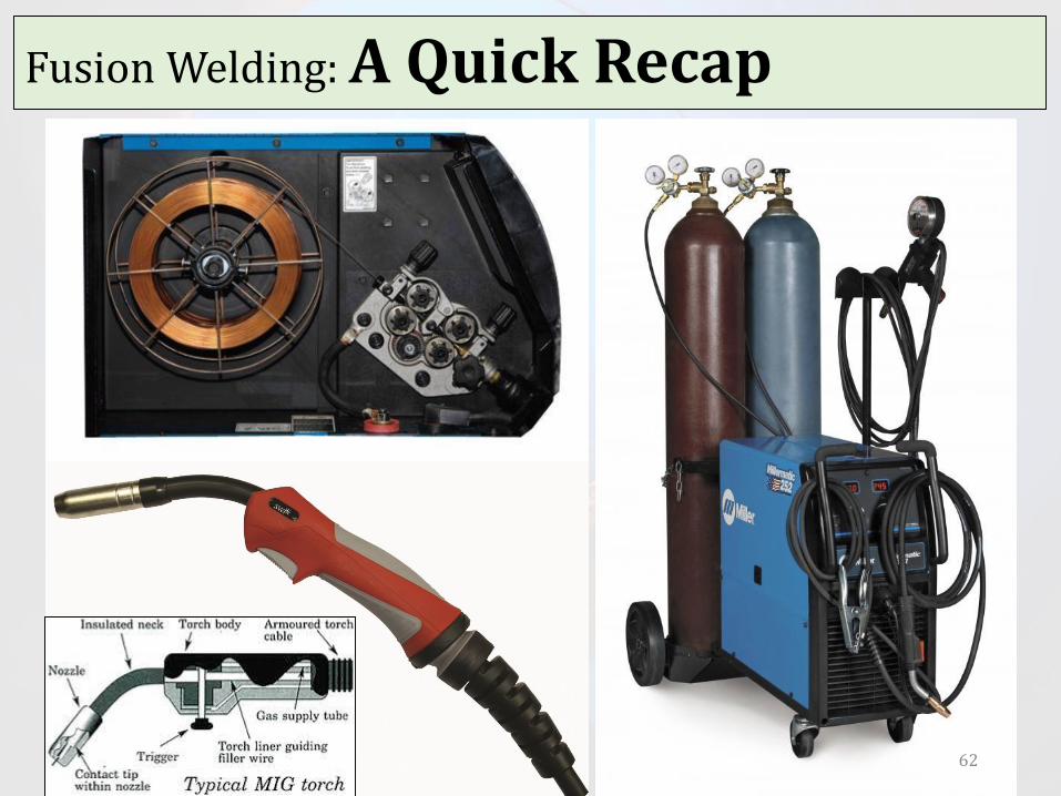
Gas Metal-arc Welding
•Formerly called metal inert-gas (MIG) welding, the weld area is shielded by an effectively inert atmosphere of argon, helium, carbon dioxide, or various other gas mixtures.
•The consumable bare wire is fed automatically through a nozzle into the weld arc by a wire-feed drive motor.
47

Fusion Welding: Arc-Welding ProcessesConsumable Electrode
Gas Metal-arc Welding
48

Fusion Welding: Arc-Welding ProcessesConsumable Electrode
Gas Metal-arc Welding• The temperatures
generated in GMAW are relatively low;
• Thus the method is suitable only for sheets and sections of less than 6 mm; otherwise incompletefusion may occur.
• Pulsed-arc systems are used for thin ferrous and nonferrous metals.
49

Fusion Welding: Arc-Welding ProcessesConsumable Electrode
Gas Metal-arc Welding
50

Fusion Welding: Arc-Welding ProcessesConsumable Electrode
GMAW vs GTAW – also helpful to take a look…
51https://www.youtube.com/watch?v=Iju5tHB2UCc

Fusion Welding: Arc-Welding ProcessesConsumable Electrode
Gas Metal-arc Welding
• The GMAW process is used extensively in the metal-fabrication industry.
• Because of the relatively simple nature of the process, the training of operators is easy. The process is versatile, rapid, and economical, and welding productivity is double that of the SMAW process.
• The GMAW process can be automated easily and lends itself readily to robotics and to flexible manufacturing systems.
52

Fusion Welding: Arc-Welding Processes
Consumable Electrode
Electroslag Welding
•The arc is started between the electrode tipand the bottom of the part to be welded.
•Flux is added, which then melts by the heatof the arc.
•After the molten slag reaches the tip of the electrode, the arc is extinguished. Heat is produced continuously by the electrical resistance of the molten slag.
53

Fusion Welding: Arc-Welding ProcessesConsumable Electrode
Electroslag Welding
54

Fusion Welding: Arc-Welding ProcessesConsumable Electrode
Electroslag Welding
55

Fusion Welding: Arc-Welding ProcessesConsumable Electrode
Electroslag Welding•Capable of welding plates with thicknesses
ranging from 50 mm to more than 900 mm, and welding is done in one pass.•The travel speed of the weld is in the range
from 12 to 36 mm/min. •Weld quality is good. This process is used
for large structural-steel sections, such as heavy machinery, bridges, oil rigs, ships, and nuclear-reactor vessels.
56

Fusion Welding: Arc-Welding Processes
Electrodes for Arc-welding•Electrodes for consumable arc-welding
processes are classified according to thefollowing properties:
Strength of the deposited weld metal
Current (AC or DC)
Type of coating.
57

Fusion Welding: Arc-Welding Processes• Electrodes are
identified by numbers and letters or by color code if the numbers and letters are too small to imprint.
• Typical coated-electrodedimensions are in the range from 150 to 460 mm in length and 1.5 to 8 mm indiameter.
58

Fusion Welding: Arc-Welding Processes
Electrode Coatings
•Electrodes are coated with claylike materials that include silicate binders and powdered materials, such as oxides, carbonates, fluorides, metal alloys, cotton cellulose, and wood flour.
59

Fusion Welding: Arc-Welding ProcessesElectrode Coatings• The coating, which is brittle and takes part in
complex interactions during welding, has the following basic functions: Stabilize the arc. Generate gases to act as a shield against the
surrounding atmosphere; Control the rate at which the electrode melts. Act as a flux to protect the weld against the
formation of oxides, nitrides, and other inclusions.
Add alloying elements to the weld zone to enhance the properties of the joint.
Provide proper utilization of generated heat.60

Fusion Welding: A Quick Recap
61
Fusion Welding: A Quick Recap
62

Fusion Welding: Arc-Welding Processes
Some interesting pages to visit;
http://weldinghelmethq.com/which-welding-process-to-choose-mig-vs-tig/
http://www.wikihow.com/Weld-Stainless-Steel
http://weldingweb.com/showthread.php?18331-stainless-steel-welding-with-MIG-or-TIG
63

RW covers a number of processes in which the heat required for welding is produced by means of electrical resistance across the two components to be joined.
These processes have major advantages, such as not requiring consumable electrodes, shielding gases, or flux.
Resistance Welding
64

Resistance Welding
The total resistance is the sum of the following properties:
a. Resistances of the electrodes;b. Electrode-workpiece contact
resistance;c. Resistances of the individual parts to be
welded;d. Contact resistance between the two
workpieces to be joined (fayingsurfaces).
65

Resistance Welding
Sequence of events in resistance spot welding (a).Cross section of a spot weld, showing the weld nugget and the indentation of the electrode on the sheet surfaces (b).
66

Resistance Welding
67

Resistance Seam Welding
(a) Seam-welding process in which rotating rolls act as electrodes; (b) overlapping spots in a seam weld; (c) roll spot welds; and (d) mash seam welding.
• RSEW is a modification of spot welding wherein the electrodes are replaced by rotating wheels or rollers.
• With a high enough frequency or slow enough traverse speed, these spot welds actually overlap into a continuous seam and produce a joint that is liquid tight and gastight.
• The RSEW process is used to make the longitudinal (side) seam of cans (for household products) mufflers, gasoline tanks, and other containers.
68

High-Freq. Resistance Welding
• HFRW is similar to seam welding, except that high-frequency current (up to 450 kHz) is employed.
• A typical application is theproduction of butt-welded tubing or piping where the current is conducted throughtwo sliding contacts to the edges of roll-formed tubes.
• The heated edges then are pressed together by passing the tube through a pair of squeeze rolls.
• Any flash formed is then trimmed off.
69

High-Freq. Resistance Welding
70

The Weld Joint, Quality and Testing
Three distinct zones can be identified in a typical weld joint:
• Base metal,
• Heat-affected zone,
• Weld metal.
84

The Weld Joint, Quality and Testing
Solidification of Weld Metal
•The solidification process is similar to that in casting and begins with the formation of columnar (dendritic) grains.•Because metals are much
better heat conductors than the surrounding air, the grains lie parallel to the plane of the two components being welded.
85

The Weld Joint, Quality and Testing
Solidification of Weld Metal(a) A deep weld and (b) a shallow weld; (c) weld bead on a cold-rolled nickel strip produced by a laser beam. (d) Microhardness (HV) profile across a weld bead.
86

The Weld Joint, Quality and Testing
Heat-Affected Zone• The heat-affected zone (HAZ) is within the base
metal itself. It has a microstructure different from that of the base metal prior to welding.
• The heat applied during welding recrystallizes the elongated grains of the cold worked base metal. On the one hand, grains that are away from the weld
metal will recrystallize into fine, equiaxed grains. On the other hand, grains close to the weld metal have
been subjected to elevated temperatures for a longer time. Consequently, the grains will grow in size (grain growth), and this region will be softer and have lower strength. Such a joint will be weakest at its HAZ.
87

The Weld Joint, Quality and Testing
Weld Quality: Major DiscontinuitiesPorosity in welds may be caused by, • Gases released during melting of the weld area
and trapped during solidification,• Chemical reactions during welding,• Contaminants.
88

The Weld Joint, Quality and Testing
Weld Quality: Major Discontinuities
Slag Inclusions are compounds such as oxides, fluxes, and electrode coating materials that are trapped in the weld zone. *If shielding gases are not effective during welding, contamination from the environment also may contribute to such inclusions.
Slag inclusions can be prevented by the following practices:• Cleaning the weld-bead surface before the next layer is
deposited.• Providing sufficient shielding gas.• Redesigning the joint to permit sufficient space for proper
manipulation of molten weld metal. 89

The Weld Joint, Quality and Testing
Weld Quality: Major Discontinuities
Incomplete Fusion produces poor weld beads. A better weld can be obtained by,
•Raising the temperature of the base metal or
•Cleaning the weld area before welding.
90

The Weld Joint, Quality and Testing
Weld Quality: Major Discontinuities
Incomplete Penetration occurs when the depth of the welded joint is insufficient. Penetration can be improved by the following practices:Increasing the heat input,Reducing the travel speed during the
welding,Ensuring that the surfaces to be
joined fit each other properly.91

The Weld Joint, Quality and Testing
Weld Quality: Major Discontinuities
Weld Profile
• Underfilling results when the joint is not filled with the proper amount of weld.
• Undercutting results from the melting away of the base metal and the consequent generation of a groove. If it is deep or sharp, an undercut can act as a stress raiser.
• Overlap is a surface discontinuity usually caused by poor welding practice or by the selection of improper materials.
92

The Weld Joint, Quality and Testing
Weld Quality: Major Discontinuities
Weld Profile is important for,
• its effects on the strength,
• the appearance of the weld and
•because it can indicate incomplete fusionor the presence of slag inclusions in multiple-layer welds.
93

The Weld Joint, Quality and Testing
Weld Quality: Major Discontinuities
Weld Profile
94

The Weld Joint, Quality and Testing
Weld Quality: Major Discontinuities
Cracks generally result from a combination of the following factors:• Temperature gradients that cause thermal
stresses in the weld zone.• Variations in the composition of the weld zone
that cause different rates of contraction during cooling.
• Fracturing of grain boundaries, caused by the segregation of such elements as sulfur to the grain boundaries.
• Inability of the weld metal to contract during cooling.
95

The Weld Joint, Quality and Testing
Weld Quality: Different types of Cracks
96

The Weld Joint, Quality and Testing
Weld Quality: Some Examples
97

The Weld Joint, Quality and Testing
Weld Quality: Some Examples
98

The Weld Joint, Quality and Testing
Weld Quality: Major Discontinuities
Residual Stresses: Due to localized heating and cooling during welding, the expansion and contraction of the weld area causes residual stresses in the workpiece.
Residual stresses can lead to the following defects:• Distortion, warping, and buckling of the welded
parts,• Stress-corrosion cracking,• Reduced fatigue life of the welded structure.
99

The Weld Joint, Quality and Testing
Weld Quality: Major DiscontinuitiesResidual StressesBefore welding, the structure is stress free.
As weld bead solidifies, both the weld bead and the surrounding material cool to room temperature.
As these materials cool, they tend to contract, but are constrained bythe bulk of the weldment.
The result is that the weldment and residual stresses develop.
100

The Weld Joint, Quality and Testing
Weld Quality: Major Discontinuities
Residual Stresses: Stress RelievingThe problems caused by residual stresses (such as distortion, buckling, and cracking) can be reduced by preheating the base metal or the parts to be welded. Preheating reduces distortion by reducing
the cooling rate and the level of thermal stresses developed (by lowering the elastic modulus).
This technique also reduces shrinkage and possible cracking of the joint.
101

Joint Design and Process Selection
Design Guidelines:•Product design should minimize the
number of welds because, unless automated, welding can be costly.•Weld location should be selected so as to
avoid excessive stresses or stress concentrations in the welded structure.•Weld location should be selected so as not
to interfere with any subsequent processingof the joined components,
102

Joint Design and Process Selection
•Components should fit properly prior to welding. The method used to prepareedges, such as sawing, machining, or shearing, also can affect weld quality.•The need for edge preparation should
be avoided or minimized.•Weld-bead size should be as small as
possible, while maintaining the strength of the joint, to conserve weldmetal and for better appearance.
103

Joint Design and Process Selection
104

Joint Design and Process Selection
105

Joint Design and Process Selection
Welding Process Selection:The selection of a weld joint and an appropriate welding process involve the following topics;• Joint design, thickness and size of the
components, and number of joints required.•The methods used in manufacturing,•The components to be joined,•Types of materials involved, which may be
metallic or nonmetallic,•Location, accessibility, and ease of joining.106

Joint Design and Process Selection
Welding Process Selection:•App and service requirements, such as type
of loading, any stresses generated, etc.
•Costs involved in edge preparation, joining, and post-processing (machining, grinding, and finishing operations).
•Costs of equipment, materials, labor and skills required.
107

Joint Design and Process Selection
Joining Process Selection: Frankly, no single joining process has a high rating in all categories:• Arc welding, bolts, and riveting have high strength and
reliability, but generally are not suitable for joining small parts.
• Resistance welding has strength and applications for both small and large parts. However, it is not easy to inspect visually for reliability, and resistance welding has lower tolerances and reliability than other processes.
• Fasteners are useful for large parts and can be easy to inspect visually, but they are costly and do not have much design variability.
• Adhesive bonding has high design variability. However, it has relatively low strength and is difficult to visually inspect for joint integrity.
108

Joint Design and Process Selection
109

Joint Design and Process Selection
110

Thanks andbest of luck!
129