Embed Size (px)
Citation preview
Performance of TransverseJoint Grout Materials inFull-Depth Precast ConcreteBridge Deck Systems
Mohsen A. Issa,Ph.D., P.E., S.E.ProfessorDepartment of Civil andMaterials EngineeringUniversity of Illinois at ChicagoChicago, Illinois
Cyro L. Ribeiro do ValleCivil Engineer
MWH Energy & Infrastructure, Inc.Chicago, Illinois
Hiba A. Abdalla, Ph.D.Senior DesignerAlfred Benesch & CompanyChicago, Illinois
Shahid Islam, Ph.D.Corporate Engineer
Dywidag-Systems InternationalBolingbrook, Illinois
Mahmoud A. Issa, Ph.D., P.E.Project EngineerTX. Lin InternationalChicago, Illinois
precast concrete deck systems have been increasinglyused for bridge construction for three decades. Toprovide load transfer between adjacent precast slabs,
the transverse joint can be grouted using a variety of materials. Joints between precast elements may be filled withgrout, epoxy mortar, or polymer concrete to bond the twoslabs, thus making the joint itself a structural element inthe bridge. As such, transverse joints must resist vertical
Over the past three decades, bridge deckconstruction using precast concrete componentshas become the system of choice for contractorsand transportation officials. This preference forprecast concrete systems is due to the rapiderection of its relatively lightweight components,reduction in overall mobilization and equipmentcosts, and structural durability. While precastconcrete panels perform well under large andhighly repetitive loadings, the grouted jointsbetween concrete panels can becomeproblematic. This paper evaluates theperformance of four different grout materials inprecast concrete deck systems; these are SetGrout, Set 45 for normal temperatures, Set 45 forhot weather, and polymer concrete. A total of 36full-scale specimens were fabricated and testedfor vertical shear, direct tension, and flexuralcapacity. Polymer concrete was found to be thebest material for transverse joints in terms ofstrength, bond, and mode of failure. However, theuse of Set Grout is recommended in transversedeck joints due to its ease of use and satisfactoryperformance. In special cases where the joint issubjected to excessive stresses or quickresumption of traffic is critical, the properapplication of the more expensive polymerconcrete is recommended.
‘I:
92 PCI JOURNAL
shear when wheel loads cross thetransverse joint and bending inducedby moving vehicular loads. Dryingshrinkage of the grouting material andtransverse shortening of the precastconcrete slabs further subject the jointto direct tension.
Testing of individual transversejoint materials under vertical shear,tensile, and flexural loading is essential to establish grout quality and serviceability. If the grouting material isnot strong enough to resist in-servicestresses, cracking will result. Leakingjoints allow penetration of foreign materials, gradually weakening the joint.Investigations of bridge joints over theyears have revealed that many transverse joints exhibit leakage and vertical faults, requiring extensive maintenance and costly repairs.
While new construction materialswere rapidly being developed andmarketed, many of these materialswere not adequately evaluated undersituations encountered in actual structures. Set 45, Set 45 hot weather(HW), Set Grout, and polymer concrete are the most commonly usedjoint materials in civil infrastructure.
The purpose of this research is to investigate the behavior of transversejoints grouted with these grout materials in precast concrete segments underin-service conditions of vertical shear,tension, and bending, thus providingengineers with realistic guidelines fordetermining the best grout material foruse under various conditions.*
LITERATURE REVIEWIn 1995, Gulyas et al.1 reported an
evaluation of precast panel keyways.The experiments consisted of verticalshear, direct tension, and direct longitudinal shear tests of joints filled withnon-shrink and Set 45 grout materials.Composite assemblies prepared withSet 45 exhibited better behavior thannon-shrink grout in each mode of testing. The drying shrinkage of Set 45mortar was found to be significantlylower than concrete with a 0.32 watercementitious material ratio (w/cm).The effect of carbonation at the inter-
* All grouting materials used in this study are productsof Master Builders.
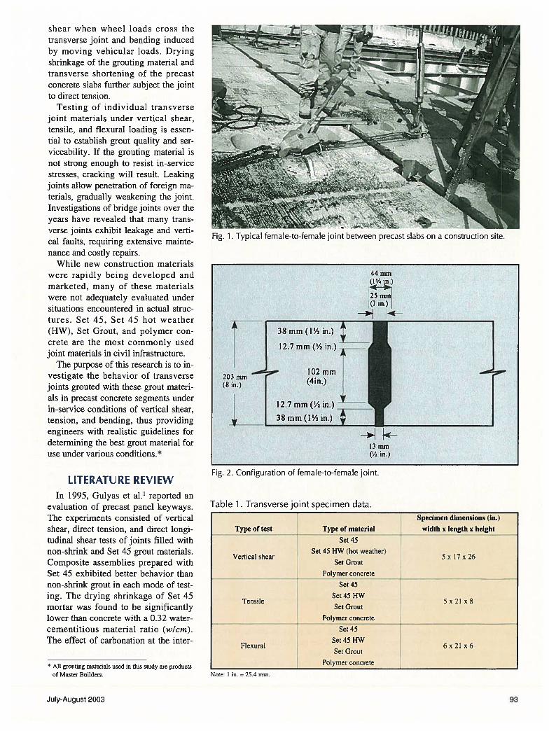
Fig. 2. Configuration of female-to-female joint.
Table 1. Transverse joint specimen data.
Note: I in. = 25.4 mm.
44mm
13 mm(V2 in.)
Type of test
Vertical shear
Specimen dimensions (in.)
width x length x heightType of material
Set 45
Set 45 HW (hot weather)
Set Grout
Polymer concrete
Set 45
Set 45 I-lW
Set Grout
Polymer concrele
Tensile
5 x 17 x 26
Flexural
Set 45
5x2l x8
Set 45 HW
Set Grout
Polymer concrete
6x2l x6
July-August 2003 93
face of the concrete produced lowerbond strength with the Set 45 composite system. It was concluded that composite testing of the grouted assemblies, rather than component materials
Tension load
testing, is a more accurate way toevaluate the performance of the grouting materials.
In 1975, Kropp et al.2 investigatedthree different shapes of joints. A
common form (match-cast) was usedto ensure a good male-to-female fitting. It was concluded that the flatshape joint was superior to the others.
In 1995, Issa et al.3’4’5 carried out visual inspections on existing joint systems in bridges throughout the nation.The tongue-and-groove joint wasfound impractical due to difficultiesencountered with the grouting process.The butt joint was found ineffectivebecause it caused leakage through thejoint as a result of the deck being intension. The female-to-female jointwith a closed section at the bottomcreated some problems in matchingthe adjacent slab and, as a result, theslabs were damaged under repeatedwheel loads. Cracking, spalling, andleakage at the precast slab joint wereobserved. Bridge decks with female-to-female joints and openings at thetop and bottom experienced virtuallyno problem.
The conclusion of that investigationwas that the transverse joints betweenthe precast slabs should be female-to-female (shear key) and have a minimum nominal width of 1/4 in. (32mm) at the top and “2 in. (13 mm) atthe bottom. Longitudinal post-tensioning was also recommended to securetightness of the joints.
EXPERIMENTAL PROGRAM
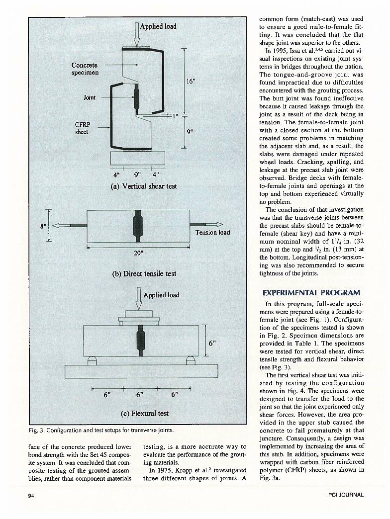
In this program, full-scale specimens were prepared using a female-to-female joint (see Fig. 1). Configuration of the specimens tested is shownin Fig. 2. Specimen dimensions areprovided in Table 1. The specimenswere tested for vertical shear, directtensile strength and flexural behavior(see Fig. 3).
The first vertical shear test was initiated by testing the configurationshown in Fig. 4. The specimens weredesigned to transfer the load to thejoint so that the joint experienced onlyshear forces. However, the area provided in the upper stub caused theconcrete to fail prematurely at thatjuncture. Consequently, a design wasimplemented by increasing the area ofthis stub. In addition, specimens werewrapped with carbon fiber reinforcedpolymer (CFRP) sheets, as shown inFig. 3a.
16”
Concretespecimen
Joint
CFRPsheet
(a) Vertical shear test
4t1
1420”
(b) Direct tensile test
Applied load
A
.i6”
(c) Flexural test
Fig. 3. Configuration and test setups for transverse joints.
94 PCI JOURNAL
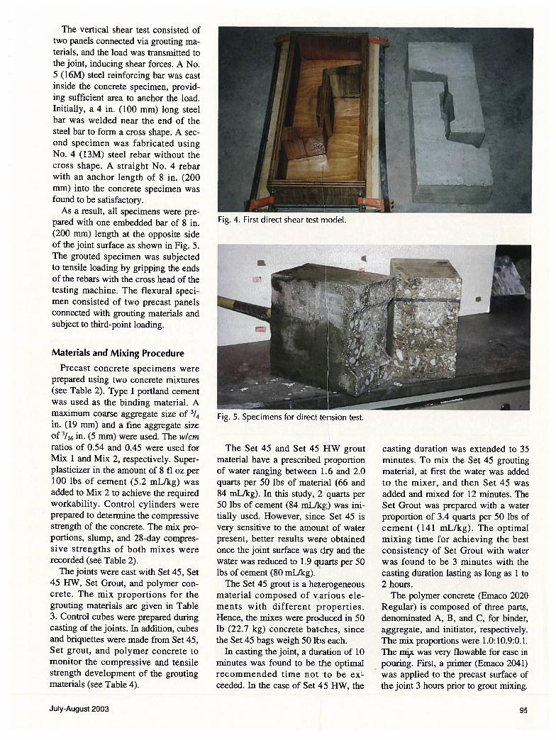
The vertical shear test consisted oftwo panels connected via grouting materials, and the load was transmitted tothe joint, inducing shear forces. A No.5 (16M) steel reinforcing bar was castinside the concrete specimen, providing sufficient area to anchor the load.Initially, a 4 in. (100 mm) long steelbar was welded near the end of thesteel bar to form a cross shape. A second specimen was fabricated usingNo. 4 (13M) steel rebar without thecross shape. A straight No. 4 rebarwith an anchor length of 8 in. (200mm) into the concrete specimen wasfound to be satisfactory.
As a result, all specimens were prepared with one embedded bar of 8 in.(200 mm) length at the opposite sideof the joint surface as shown in Fig. 5.The grouted specimen was subjectedto tensile loading by gripping the endsof the rebars with the cross head of thetesting machine. The flexural specimen consisted of two precast panelsconnected with grouting materials andsubject to third-point loading.
Materials and Mixing Procedure
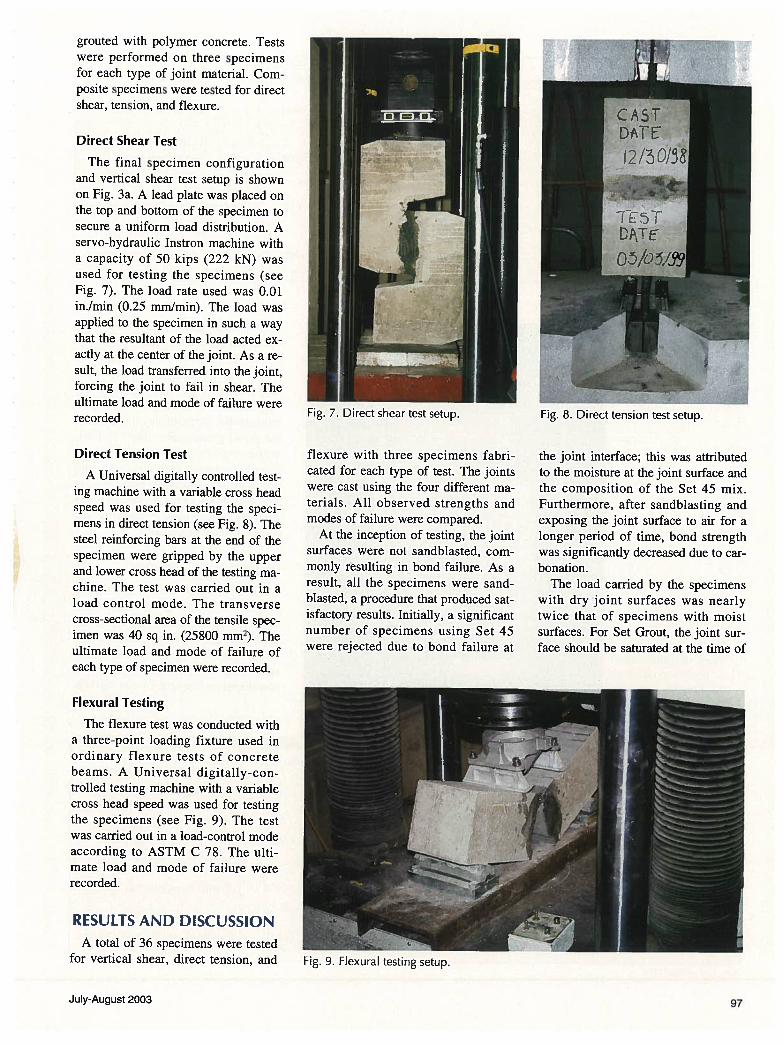
Precast concrete specimens wereprepared using two concrete mixtures(see Table 2). Type I portland cementwas used as the binding material. Amaximum coarse aggregate size of 3/4
in. (19 mm) and a fine aggregate sizeof ‘J6 in. (5 mm) were used. The w/cmratios of 0.54 and 0.45 were used forMix 1 and Mix 2, respectively. Super-plasticizer in the amount of 8 fl oz per100 lbs of cement (5.2 mL/kg) wasadded to Mix 2 to achieve the requiredworkability. Control cylinders wereprepared to determine the compressivestrength of the concrete. The mix proportions, slump, and 28-day compressive strengths of both mixes wererecorded (see Table 2).
The joints were cast with Set 45, Set45 11W, Set Grout, and polymer concrete. The mix proportions for thegrouting materials are given in Table3. Control cubes were prepared duringcasting of the joints. In addition, cubesand briquettes were made from Set 45,Set grout, and polymer concrete tomonitor the compressive and tensilestrength development of the groutingmaterials (see Table 4).
The Set 45 and Set 45 FEW groutmaterial have a prescribed proportionof water ranging between 1.6 and 2.0quarts per 50 lbs of material (66 and84 mL/kg). In this study, 2 quarts per50 lbs of cement (84 mL/kg,) was initially used. However, since Set 45 isvery sensitive to the amount of waterpresent, better results were obtainedonce the joint surface was dry and thewater was reduced to 1.9 quarts per 50lbs of cement (80 mL/kg).
The Set 45 grout is a he:erogeneousmaterial composed of various elements with different properties.Hence, the mixes were produced in 50lb (22.7 kg) concrete batches, sincethe Set 45 bags weigh 50 lbs each.
In casting the joint, a duiration of 10minutes was found to be the optimalrecommended time not to be ex’ceeded. In the case of Set 45 11W, the
casting duration was extended to 35minutes. To mix the Set 45 groutingmaterial, at first the water was addedto the mixer, and then Set 45 wasadded and mixed for 12 minutes. TheSet Grout was prepared with a waterproportion of 3.4 quarts per 50 lbs ofcement (141 mL/kg). The optimalmixing time for achieving the bestconsistency of Set Grout with waterwas found to be 3 minutes with thecasting duration lasting as long as 1 to2 hours.
The polymer concrete (Emaco 2020Regular) is composed of three parts,denominated A, B, and C, for binder,aggregate, and initiator, respectively.The mix proportions were 1.0:10.9:0.1.The mix was very flowable for ease inpouring. First, a primer (Emaco 2041)was applied to the precast surface ofthe joint 3 hours prior to grout mixing.
Fig. 4. First direct shear test model.
Fig. 5. Specimens for direct tension test.
July-August 2003 95
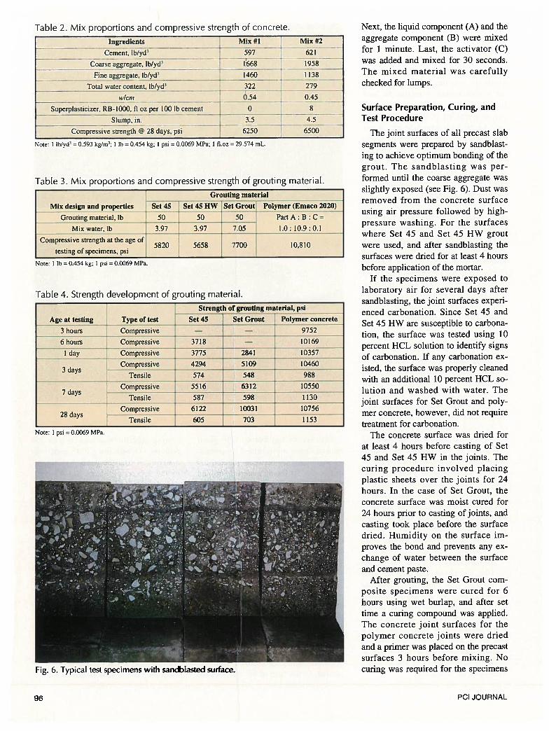
Table 2. Mix proportions and compressive strength of concrete.
Ingredients Mix #1 Mix #2 —
— CemenLlb/yd3 597 T 621
coarse_aggregate, lb/yd3 668 1958
Fine aggregate, lb/yd3 1460 1138
Total water content. Ib/yd3 322 279
w/cm 0.54 0.45
Superplasticizer, RB-bOO. fI ot per 100 lb cement 0 8
Slump, in. 3.5 4.5
Cotpressive strength @ 28 days, psi b250 6500
ote: 1 tb/yd = 0.593 kg/ms; I ib=0.454kg; 1 psi = 0.0069 MPa; 1 fl.oz = 29.574 mL,
Table 3. Mix proportions and compressive strength of grouting material.
E Groutingmaterial
Mix design and properties Set 45 - Set 45HW Set Grout Polymer (Emaco 2020)_
Grouting material, lb 50 50 — 50 Part A B C =
Mix water, lb 3.97 3.97 7.05 1.0: 10.9 0.1
compressive strength at the age of5820 5658 7700 10,810
testing of specimens, psi
Note: 1 lb = 0.454 kg; 1 psi = 0.0069 MPa.
Table 4. Strength development of grouting material.
Strength of grouting material, psi
Age at testing Type of test Set 45 Set Grout Polymer concrete
3 hours compressive — — 9752
6 hours Compressive 3718 — 10169
— I day — Compressive 3775 2841 10357
3dCompressive 4294 5109 10460
aysTensile 574 548 988
Compressive 5516 6312 105507days
Tensile 587 598 1130
Compressive 6122 10031 1075628days
TensLle 605 703 1153
Next, the liquid component (A) and theaggregate component (B) were mixedfor 1 minute. Last, the activator (C)was added and mixed for 30 seconds.The mixed material was carefullychecked for lumps.
Surface Preparation, Curing, andTest Procedure
The joint surfaces of all precast slabsegments were prepared by sandblasting to achieve optimum bonding of thegrout. The sandblasting was performed until the coarse aggregate wasslightly exposed (see Fig. 6). Dust wasremoved from the concrete surfaceusing air pressure followed by high-pressure washing. For the surfaceswhere Set 45 and Set 45 HW groutwere used, and after sandblasting thesurfaces were dried for at least 4 hoursbefore application of the mortar.
If the specimens were exposed tolaboratory air for several days aftersandblasting, the joint surfaces experienced carbonation. Since Set 45 andSet 45 HW are susceptible to carbonation, the surface was tested using 10percent HCL solution to identify signsof carbonation. If any carbonation existed, the surface was properly cleanedwith an additional 10 percent HCL solution and washed with water. Thejoint surfaces for Set Grout and polymer concrete, however, did not requiretreatment for carbonation.
The concrete surface was dried forat least 4 hours before casting of Set45 and Set 45 HW in the joints. Thecuring procedure involved placingplastic sheets over the joints for 24hours. In the case of Set Grout, theconcrete surface was moist cured for24 hours prior to casting of joints, andcasting took place before the surfacedried. Humidity on the surface improves the bond and prevents any exchange of water between the surfaceand cement paste.
After grouting, the Set Grout composite specimens were cured for 6hours using wet burlap, and after settime a curing compound was applied.The concrete joint surfaces for thepolymer concrete joints were driedand a primer was placed on the precastsurfaces 3 hours before mixing. Nocuring was required for the specimens
Note: 1 psi = 0.0069 MPa.
Fig. 6. Typical test specimens with sandblasted surface.
96 PCI JOURNAL
grouted with polymer concrete. Testswere performed on three specimensfor each type of joint material. Composite specimens were tested for directshear, tension, and flexure.
Direct Shear Test
The final specimen configurationand vertical shear test setup is shownon Fig. 3a. A lead plate was placed onthe top and bottom of the specimen tosecure a uniform load distribution. Aservo-hydraulic Instron machine witha capacity of 50 kips (222 kN) wasused for testing the specimens (seeFig. 7). The load rate used was 0.01in./min (0.25 mm/mm). The load wasapplied to the specimen in such a waythat the resultant of the load acted exactly at the center of the joint. As a result, the load transferred into the joint,forcing the joint to fail in shear. Theultimate load and mode of failure wererecorded.
Direct Tension Test
A Universal digitally controlled testing machine with a variable cross headspeed was used for testing the specimens in direct tension (see Fig. 8). Thesteel reinforcing bars at the end of thespecimen were gripped by the upperand lower cross head of the testing machine. The test was carried out in aload control mode. The transversecross-sectional area of the tensile specimen was 40 sq in. (25800 mm2). Theultimate load and mode of failure ofeach type of specimen were recorded.
Flexural TestingThe flexure test was conducted with
a three-point loading fixture used inordinary flexure tests of concretebeams. A Universal digitally-controlled testing machine with a variablecross head speed was used for testingthe specimens (see Fig. 9). The testwas carried out in a load-control modeaccording to ASTM C 78. The ultimate load and mode of failure wererecorded.
RESULTS AND DISCUSSIONA total of 36 specimens were tested
for vertical shear, direct tension, and
flexure with three specimens fabricated for each type of test. The jointswere cast using the four different materials. All observed strengths andmodes of failure were compared.
At the inception of testing, the jointsurfaces were not sandblasted, commonly resulting in bond failure. As aresult, all the specimens were sand-blasted, a procedure that produced satisfactory results. Initially, a significantnumber of specimens using Set 45were rejected due to bond failure at
the joint interface; this was attributedto the moisture at the joint surface andthe composition of the Set 45 mix.Furthermore, after sandblasting andexposing the joint surface to air for alonger period of time, bond strengthwas significantly decreased due to carbonation.
The load carried by the specimenswith dry joint surfaces was nearlytwice that of specimens with moistsurfaces. For Set Grout, the joint surface should be saturated at the time of
Fig. 7. Direct shear test setup. Fig. 8. Direct tension test setup.
— p
Fig. 9. Flexural testing setup.
July-August 2003 97
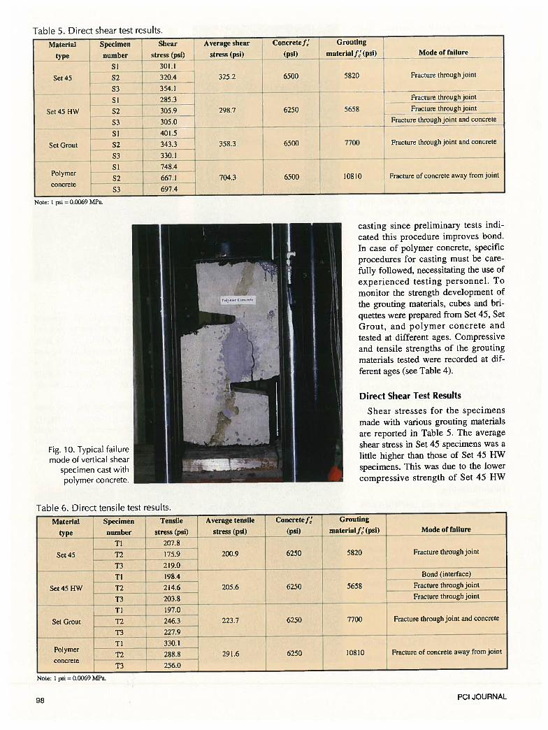
Table 5. Direct shear test results.
Note: I psi = 00069 MPa.
Fig. 10. Typical failuremode of vertical shear
specimen cast withpolymer concrete.
casting since preliminary tests indicated this procedure improves bond.In case of polymer concrete, specificprocedures for casting must be carefully followed, necessitating the use ofexperienced testing personnel. Tomonitor the strength development of
the grouting materials, cubes and briquettes were prepared from Set 45, SetGrout, and polymer concrete andtested at different ages. Compressiveand tensile strengths of the groutingmaterials tested were recorded at different ages (see Table 4).
Direct Shear Test Results
Shear stresses for the specimensmade with various grouting materialsare reported in Table 5. The averageshear stress in Set 45 specimens was alittle higher than those of Set 45 HWspecimens. This was due to the lowercompressive strength of Set 45 HW
Table 6. Direct tensile test results.
Material Specimen Tensile Average tensile Concretef Grouting
type number stress (psi) stress (psi) (psi) materialf’ (psi) Mode of failure
TI 207.8 TSet 45 T2 —
1759 200 9 6250 5820 Fracture through Joint
T3 219.0
TI 198.4 Bond (interface)
Set 45 HW T2 214.6 205.6 6250 5658 Fracture through joint
T3
203.8 Fracture through joint
TI 197.0
Set Grout T2 246.3 223.7 6250 7700 Fracture through joint and concrete
T3 227.9
TI 330.1Polymer —
- -
T2 288.8 291.6 6250 10810 Fracture of concrete away from jointconcrete —-----
T3 256.0 -
Note: I psi = 0.0069 MPa.
Material Specimen Average shear
stress (psi)type number
SI
Set45 S2
S3
SI
Set45HW S2
Concretef’
(psi)
GroutingShear
stress (psi) -
301.1
320.4 325.2
354.1
285.3 -
305.9 ‘- 298.7
305.0
401.5 - _jI343.3 v 358.3
6500
materiaJf’(psi)[ — Mode of failure
5820
Set Grout
S3
SI
S2
S3
SI
S2
S3
Fracture through joint
Polymer
concrete
330.1
748.4
667.1
697.4
-——--•-1-——----•----—Fracture through Joint
6250 5658 I Fiacture thruugh joint
Fractuie through joint and concrete
6500 7700 Fracture through joint and concrete
6500 10810704.3 Fracture of concrete away from joint
98 PCI JOURNAL
grouting material. Failure was initiatedby fracture through the joint. The average shear stress of Set Grout specimens was higher than that of Set 45and Set 45 HW grout specimens. Failure occurred through both the jointmaterial and the surrounding concrete.
Joints cast with polymer concreteproved to be the best in terms of shearstrength, fracture, and bond behavior(Table 5). The shear strength of polymer concrete joint was twice the shearstrength of the joints cast with Set 45,Set 45 HW, and Set Grout. Bond wasexcellent and no apparent cracks wereobserved at the joint interfaces. Fracture was always induced away fromthe joint in the concrete (see Fig. 10).
Direct Tension Test Results
The observed tensile stress valuesfor the specimens made with variousgrouting materials are listed in Table6. It can be seen that the tensilestresses of specimens with Set 45 andSet 45 HW are almost the same. In allspecimens cast with Set 45 and Set 45HW grout material, failure wasthrough the joint, with the exceptionof one Set 45 HW specimen whichfailed at the bond interface. The average tensile stress for the Set Groutspecimens was higher than that of Set45 and Set 45 HW specimens. Failurein the Set Grout specimens always occurred in both the joint and the surrounding concrete. Hence, better bondwas attributed to this type of material.
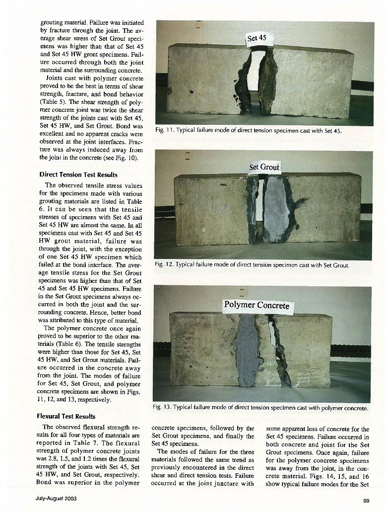
The polymer concrete once againproved to be superior to the other materials (Table 6). The tensile strengthswere higher than those for Set 45, Set45 HW, and Set Grout materials. Failure occurred in the concrete awayfrom the joint. The modes of failurefor Set 45, Set Grout, and polymerconcrete specimens are shown in Figs.11, 12, and 13, respectively.
Flexural Test Results
The observed flexural strength resuits for all four types of materials arereported in Table 7. The flexuralstrength of polymer concrete jointswas 2.8, 1.5, and 1.2 times the flexuralstrength of the joints with Set 45, Set45 HW, and Set Grout, respectively.Bond was superior in the polymer
concrete specimens, followed by theSet Grout specimens, and finally theSet 45 specimens.
The modes of failure for the threematerials followed the same trend aspreviously encountered in the directshear and direct tension tests. Failureoccurred at the joint juncture with
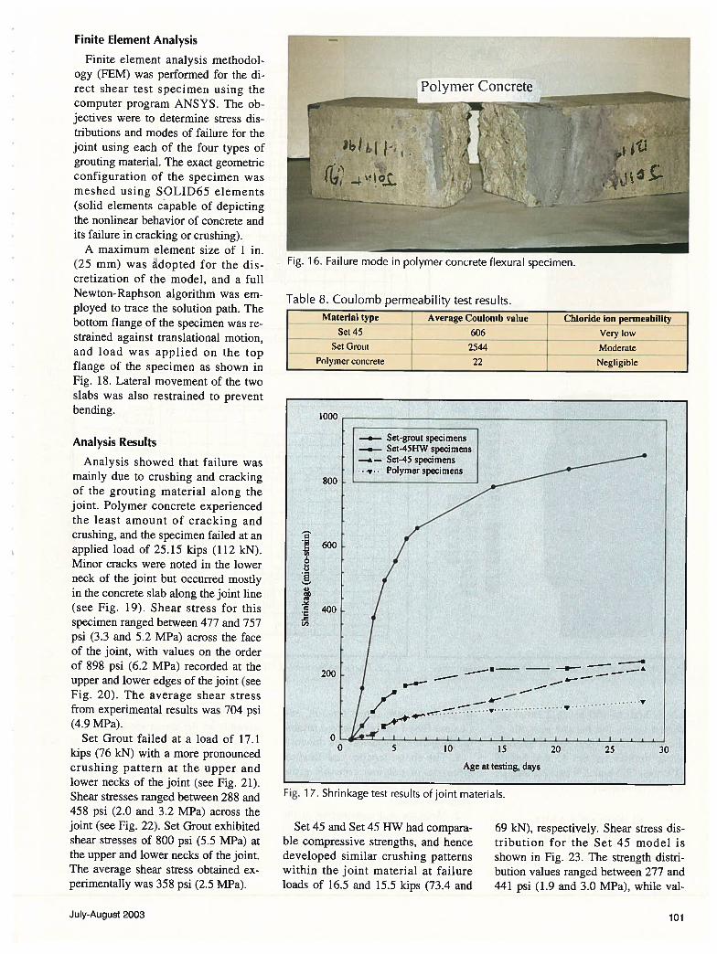
some apparent loss of concrete for theSet 45 specimens. Failure occurred inboth concrete and joint for the SetGrout specimens. Once again, failurefor the polymer concrete specimenswas away from the joint, in the concrete material. Figs. 14, 15, and 16show typical failure modes for the Set
Fig. 11. Typical failure mode of direct tension specimen cast with Set 45.
Set Grout---J
Fig. 12. Typical failure mode of direct tension specimen cast with Set Grout.
Fig. 13. Typical failure mode of direct tension specimen cast with polymer concrete.
July-August 2003 99
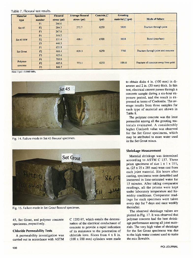
Table 7. Flexural test results.
Note: I psi = 0.0069 MPa.
to obtain disks 4 in. (100 mm) in diameter and 2 in. (50 mm) thick. In thistest, electrical current passes through aconcrete sample during a six-hour exposure period, and the result is expressed in terms of Coulombs. The average results from three samples foreach type of material are shown inTable 8.
The polymer concrete was the leastpermeable among all the grouting materials evaluated. A considerablyhigher Coulomb value was observedfor the Set Grout specimens, whichmay be attributed to more water usedin the Set Grout mixes.
45, Set Grout, and polymer concretespecimens, respectively.
Chloride Permeability Tests
A permeability investigation wascarried out in accordance with ASTM
C 1202-97, which entails the determination of the electrical conductance ofconcrete to provide a rapid indicationof its resistance to the penetration ofchloride ions. Slices from 4 x 8 in.(100 x 200 mm) cylinders were made
Shrinkage Measurement
Material shrinkage was determinedaccording to ASTM C 157. Threeprism specimens of size 1 x 1 x 111/4
in. (25 x 25 x 285 mm) were cast fromeach joint material. Six hours aftercasting, specimens were demolded andimmersed in lime-saturated water for15 minutes. After taking comparatorreadings, all the prisms were keptunder laboratory temperature and humidity conditions. Comparator readings for each specimen were takenevery day for 7 days and once weeklythereafter.
The observed shrinkage values areplotted in Fig. 17. It was observed thatpolymer concrete had the best shrinkage performance among all joint materials. The very high value of shrinkagefor the Set Grout specimens was due
to the high water content used to makethe mix flowable.
Specimen
number
Fl
Flexural Average flexural
stress (psi) stress (psi)Material
type
Set 45
Set 45 HW
Concretej’ Grouting
(psi) niaterialf (psi) — 14ode of failure --
Set Grout
266.6
F2 -. 284.3 —
F3 L 267.6
Fl 516.5
F2 L 531.4
F3 446.5
Fl 633.9
F2 601.4
F3 J 625.6
Fl 783.9
F2 685.6
F3 849.7
272.7 6250 5820 Fracture through joint
498.1 . 6500 5658 Bond (interface)
--
Polymer
concrete
620.3
773.1
6250
6250
7700 Fracture through joint and concrete
10810 Fracture of concrete away from joint
Fig. 14. Failure mode in Set 45 flexural specimen.
Fig. 15. Failure mode in Set Grout flexural specimen.
100 PCI JOURNAL
Finite Element Analysis
Finite element analysis methodology (FEM) was performed for the direct shear test specimen using thecomputer program ANSYS. The objectives were to determine stress distributions and modes of failure for thejoint using each of the four types ofgrouting material. The exact geometricconfiguration of the specimen wasmeshed using SOLID65 elements(solid elements capable of depictingthe nonlinear behavior of concrete andits failure in cracking or crushing).
A maximum element size of 1 in.(25 mm) was adopted for the discretization of the model, and a fullNewton-Raphson algorithm was employed to trace the solution path. Thebottom flange of the specimen was restrained against translational motion,and load was applied on the topflange of the specimen as shown inFig. 18. Lateral movement of the twoslabs was also restrained to preventbending.
Analysis Results
Analysis showed that failure wasmainly due to crushing and crackingof the grouting material along thejoint. Polymer concrete experiencedthe least amount of cracking andcrushing, and the specimen failed at anapplied load of 25.15 kips (112 kN).Minor cracks were noted in the lowerneck of the joint but occurred mostlyin the concrete slab along the joint line(see Fig. 19). Shear stress for thisspecimen ranged between 477 and 757psi (3.3 and 5.2 MPa) across the faceof the joint, with values on the orderof 898 psi (6.2 MPa) recorded at theupper and lower edges of the joint (seeFig. 20). The average shear stressfrom experimental results was 704 psi(4.9 MPa).
Set Grout failed at a load of 17.1kips (76 kN) with a more pronouncedcrushing pattern at the upper andlower necks of the joint (see Fig. 21).Shear stresses ranged between 288 and458 psi (2.0 and 3.2 MPa) across thejoint (see Fig. 22). Set Grout exhibitedshear stresses of 800 psi (5.5 MPa) atthe upper and lower necks of the joint.The average shear stress obtained experimentally was 358 psi (2.5 MPa).
1000
800
600
C.>
1)DU‘.
. 400
.
&
200
Fig. 17. Shrinkage test results of joint materials.
Set 45 and Set 45 HW had comparable compressive strengths, and hencedeveloped similar crushing patternswithin the joint material at failureloads of 16.5 and 15.5 kips (73.4 and
69 kN), respectively. Shear stress distribution for the Set 45 model isshown in Fig. 23. The strength distribution values ranged between 277 and441 psi (1.9 and 3.0 MPa), while val
pPolymer Concrete
Fig. 16. Failure mode in polymer concrete flexural specimen.
Table 8. Coulomb permeability test results.Material type Average Coulomb value Chloride ion permeability
Set 45 606 Very low
Set Grout 2544 Moderate
Polymer concrete 22 Negligible
00 5 10 15 20 25 30
Age at testing, days
July-August 2003 101
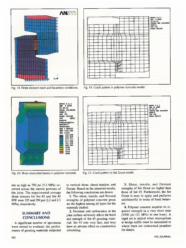
Fig. 18. Finite element mesh and boundary conditions.
LLLfflLEE
Fig. 19. Crack pattern in polymer concrete model.
Fig. 20. Shear stress distribution in polymer concrete.
— 1 I I II I II
1 1 ii -1——
. II
L II\ .‘
Fig. 21. Crack pattern in Set Grout model.
ues as high as 750 psi (5.2 MPa) occuned across the narrow portions ofthe joint. The experimental averageshear stresses for Set 45 and Set 45HW were 325 and 299 psi (2.2 and 2.1MPa), respectively.
SUMMARY ANDCONCLUSIONS
A significant number of specimenswere tested to evaluate the performance of grouting materials subjected
to vertical shear, direct tension, andflexure. Based on the observed results,the following conclusions are drawn:
1. The shear, tensile, and flexuralstrengths of polymer concrete groutare the highest among all types for thematerials studied.
2. Moisture and carbonation at thejoint surface adversely affect the bondand strength of Set 45 grouting material. Set 45 sets very fast, and mayhave an adverse effect on constructionscheduling.
3. Shear, tensile, and flexuralstrengths of Set Grout are higher thanthose of Set 45. Furthermore, the SetGrout is easy to apply and performssatisfactorily in terms of bond behavior.
4. Polymer concrete acquires its required strength in a very short time[4500 psi (31 MPa) in one hour]. Arapid set is critical when interruptionsto bridge traffic must be minimized orwhere there are contractual penaltiesfor delays.
mqols 5.5.18 2000
16:42 11CP.ACKO HD CRVS)N0STEP23130 107185. 831293
315Y3 5.5.1sop 8 200016; 38:4S000141. S0L1!1X0N5T0P1nm =10T1910. 831293sox (14310)
PowerOraphicsEPACET1AVIESt4at
DOIX =. 00445?5830 =196.638SOX =1459
196.630836.92?477.217617. 606757.735839.084103811791319
‘— 1459
,I I.i I I
R3520 5.5.1sEP 14 200010; 37; 08CROCKS 1400 C1W58NOITEPI51JB 10TXMRO. 566101
I —.--. =
11 I I —
HiiP
102 PCI JOURNAL
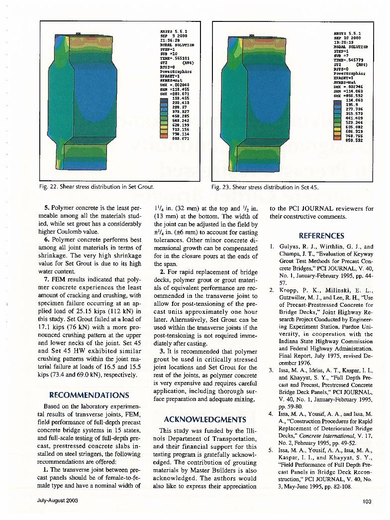
Fig. 22. Shear stress distribution in Set Grout. Fig. 23. Shear stress distribution in Set 45.
5. Polymer concrete is the least permeable among all the materials studied, while set grout has a considerablyhigher Coulomb value.
6. Polymer concrete performs bestamong all joint materials in terms ofshrinkage. The very high shrinkagevalue for Set Grout is due to its highwater content.
7. FEM results indicated that polymer concrete experiences the leastamount of cracking and crushing, withspecimen failure occurring at an applied load of 25.15 kips (112 kN) inthis study. Set Grout failed at a load of17.1 kips (76 kN) with a more pronounced crushing pattern at the upperand lower necks of the joint. Set 45and Set 45 HW exhibited similarcrushing patterns within the joint material failure at loads of 16.5 and 15.5kips (73.4 and 69.0 kiN), respectively.
RECOMMENDATIONSBased on the laboratory experimen
tal results of transverse joints, FEM,field performance of full-depth precastconcrete bridge systems in 15 states,and full-scale testing of full-depth precast, prestressed concrete slabs installed on steel stringers, the followingrecommendations are offered:
1. The transverse joint between precast panels should be of female-to-female type and have a nominal width of
11/4 in. (32 mm) at the top and 1/2 in.(13 mm) at the bottom. The width ofthe joint can be adjusted in the field by±1/4 in. (±6 mm) to account for castingtolerances. Other minor concrete dimensional growth can be compensatedfor in the closure pours at the ends ofthe span.
2. For rapid replacement of bridgedecks, polymer grout or grout materials of equivalent performance are recommended in the transverse joint toallow for post-tensioning of the precast units approximately one hourlater. Alternatively, Set Grout can beused within the transverse joints if thepost-tensioning is not required immediately after casting.
3. It is recommended that polymergrout be used in critically stressedjoint locations and Set Grout for therest of the joints, as polymer concreteis very expensive and requires carefulapplication, including thorough surface preparation and adequate mixing.
ACKNOWLEDGMENTSThis study was funded by the Illi
nois Department of Transportation,and their financial support for thistesting program is gratefully acknowledged. The contribution of groutingmaterials by Master Builders is alsoacknowledged. The authors wouldalso like to express their appreciation
to the PCI JOURNAL reviewers fortheir constructive comments.
REFERENCES1. Gulyas, R. J., Wirthlin, G. J., and
Champa, J. T., “Evaluation of KeywayGrout Test Methods for Precast Concrete Bridges,” PCI JOURNAL, V. 40,No. 1, January-February 1995, pp. 44-57.
2. Kropp, P. K., Milinski, E. L.,Gutzwiller, M. J., and Lee, R. H., “Useof Precast-Prestressed Concrete forBridge Decks,” Joint Highway Research Project Conducted by Engineering Experiment Station, Purdue University, in cooperation with theIndiana State Highway Commissionand Federal Highway Administration.Final Report, July 1975, revised December 1976.
3. Issa, M. A., Idriss, A. T., Kaspar, I. I.,and Khayyat, S. Y., “Full Depth Precast and Precast, Prestressed ConcreteBridge Deck Panels,” PCI JOURNAL,V. 40, No. 1, January-February 1995,pp. 59-80.
4. Issa, M. A., Yousif, A. A., and Issa, M.A., “Construction Procedures for RapidReplacement of Deteriorated BridgeDecks,” Concrete International, V. 17,No. 2, February 1995, pp. 49-52.
5. Issa, M. A., Yousif, A. A., Issa, M. A.,Kaspar, I. I., and Khayyat, S. Y.,“Field Performance of Full Depth Precast Panels in Bridge Deck Reconstruction,” PCI JOURNAL, V. 40, No.3, May-June 1995, pp. 82-108.
n35 5.5.1SEP 9 200021: 36:28NOW1L S0I.1JTt OilSTEP1SlID =10TINE. 5651015YZ AVO)R5750PowerGraphiIsEFtCET=1A?DZS=tOatDOX =. 0028435814 =118.455Sax =883.071: 118.465
203.413— 288.37— 373.32?— 458.285
E= 543.242
H628.199713.156— 798.114883, 071
ARS7S 5.5.1SEP 10 200013:20:13]iOrIRJ. SOLUTIONsrxp=1uD =7TIOIE. S459Sz (WIG)R575=0PowerGraphicsEPACET1AVD.ES8aDSX =0027465814 =114.063sax =85U.532: 114.063
195.9— 277.736— 359.573— 441.409523.246605.082686.919— 768.755050.592
July-August 2003 103