Embed Size (px)
Citation preview
Joint paper: Feasibility and technical aspects of partial undergrounding of
extra high voltage power transmission lines
Following an invitation by the European Commissioner for Energy, Mr. Andris Piebalgs, in December 2009, ENTSO-E and Europacable have jointly produced this paper, outlining the feasibility and technical aspects of partial undergrounding of Extra High Voltage (EHV) power transmission lines (AC 220 kV – 400kV). The objective of this document is to provide an authoritative source of information for future transmission projects, which shall be made available to any interested party. Partial undergrounding may, in some cases, be part of a solution of transmission projects of vital interest for the development of the EU transmission network, and for that purpose the availability of agreed authoritative information on this topic is of fundamental importance. ENTSO-E and Europacable have reviewed the following dimensions of partially undergrounded transmission lines:
1) Technical aspects of extra-high voltage cross linked polyethylene (XLPE) cables 2) Integration of partial undergrounding in transmission networks 3) Environmental aspects of partial undergrounding 4) Cost aspects of partial undergrounding in general.
This paper merges the experience European Transmission System Operators (TSOs) have gained with the inclusion of underground EHV cables into their transmission networks over many years with the technical expertise of the leading XLPE EHV cable systems manufacturers in Europe. Given the complexity of integrating partial undergrounding into high voltage transmission systems, all projects will require a case-by-case analysis of the technical specifications required for partial undergrounding. Against this background ENTSO-e and Europacable have agreed to conclude a joint assessment of the fundamental aspects of partial undergrounding. It is important to stress that this paper only reflects on the technical aspects of partial undergrounding. It is not in the remit of this work to define when and where partial undergrounding could be applied to complement overhead transmission lines. This question remains to be answered by individual Transmission System Operators and, where applicable, by other national planning authorities or regulators. This paper has been sent to the European Commissioner for Energy, Mr Günther Oettinger, on 11th January 2011 and is now available to the public at the following link: http://ec.europa.eu/energy/studies/index_en.htm Brussels, 12th January 2011
Jean Verseille Thomas Neesen Chairman of ENTSO-E Secretary General Europacable System Development Committee
2
Joint paper: Feasibility and technical aspects
of partial undergrounding of extra high voltage power transmission
lines
Brussels, December 2010
3
1. Introduction
Page 4
2. Executive Summary
5
3. Partial undergrounding of Extra High Voltage power transmission lines
6
3.1 Technical aspects of high voltage cross linked polyethylene (XLPE) cables 3.1.1 History of XLPE cables 3.1.2 XLPE cable design 3.1.3 Cable length / Transport 3.1.4 Installation of XLPE cables 3.1.5 Joint bays 3.1.6 Transition stations or Cable Sealing End Compounds 3.1.7 Cable termination 3.1.8 Norms and standards, Life expectancy 3.1.9 Time to manufacture / Production capacity 3.1.10 Time to install 3.1.11 Time to test / commission
6
3.2 Integration of partial undergrounding in transmission networks 3.2.1 Transmission capacity 3.2.2 Transmission losses
10
3.3. Reliability of links with partial undergrounding 3.3.1 Reliability of cable section 3.3.2 Failure 3.3.3 Repair time 3.3.4 Consequences for TSOs at the planning stage 3.3.5 Autoreclosure functionality
11
3.4 Environmental aspects of partial undergrounding 3.4.1 Environmental impacts during operation 3.4.1.1 Trench width in directly buried cables 3.4.1.2 Use of land 3.4.1.3 Electric and Magnetic Field Exposure 3.4.1.4 Possible heating of ground 3.4.2 Environmental impacts during installation
13
3.5 Cost aspects of partial undergrounding 3.5.1 Cost of installation 3.5.2 Cost of operation
19
4. Case Study 4.1 Technical specifications 4.2 Transmission Scheme for Case Study 4.3 Type of reference cable and characteristics to be considered for the calculation 4.4 Installation parameters: 4.5 Current rating calculation and dimensions
21
5. Annex and Contact Details 25
4
1. Introduction For the purpose of this paper, ENTSO-E and Europacable agree to focus on cross-linked polyethylene XLPE (also called VPE) cables used in partial undergrounding of extra high voltage (EHV) 220 kV – 400 kV alternating current (AC) transmission lines. Direct current (DC) and submarine cables are not considered here and may be subject to a subsequent paper. We explicitly want to highlight the approach of partial undergrounding with lengths of the order of some kilometres to complement overhead lines. Technical specifications required for XLPE cable solutions in partially undergrounded sections are highly dependent upon the specific transmission capacity requirements. They will vary considerably from transmission line to transmission line. The case presented in this paper can only be considered as a guide. Therefore it is important to revise the parameters listed in this joint paper on a case-by-case basis for each transmission project. The objective of this paper is to give an overview of the parameters which need to be taken into account when reviewing a possible partial undergrounding of an EHV transmission project. Additionally, this paper provides a case study of a typical partial undergrounding requirement involving XLPE cables.
5
2. Executive Summary Following an invitation by the European Commissioner for Energy, Mr. Andris Piebalgs, in December 2009, ENTSO-E and Europacable have jointly produced this paper, outlining the feasibility and technical aspects of partial undergrounding of Extra High Voltage (EHV) power transmission lines (AC 220 kV – 400kV). The objective of this document is to provide an authoritative source of information for future transmission projects, which shall be made available to any interested party. It provides information on the feasibility and technical aspects of partial undergrounding of EHV transmission lines (AC 220 kV - 400 kV) based on the expertise of cable systems manufacturers and on the experience gained by the European Transmission System Operators with the inclusion of underground EHV cables in their systems. The document focuses on the use of 400kV XLPE cables, a technology that performs well based on established international standard IEC 62067 and is available for transmission projects. It is recognised that each transmission project is unique due to its specific features. Given the complexity of integrating partial undergrounding into high voltage transmission systems, all projects require a case by case analysis of the technical specifications. From a technical perspective, partial undergrounding can be a viable option for transmission projects of vital interest for the development of the EU transmission network. Reliability and costs are of the highest importance. The use of IEC standards for testing and qualification aims to ensure the reliability of the cable systems. Monitoring systems are available to further increase reliability. Depending on the type and scope of failure, repair times for cables can be longer than for overhead lines. As with any transmission link, also partial undergrounding requires a risk assessment by the TSO of integrating the link into the system. The Underground Cable (UGC) investment cost is typically 5 to 10 times higher than Overhead Line (OHL) costs. These cost ratios are directly related to the capacity of the link. Factor down to 3 can be reached for links with limited rating and under special favorable conditions for cable laying or in case of expensive OHL. Factors above 10 can be reached for high capacity double circuit links and if specific structures are needed. Where partial undergrounding is considered, the above multiples apply to the undergrounded part of the link; therefore any decision for partial undergrounding needs to take the whole economical balance of the transmission projects into account. Such a decision must also be carefully analysed with all stakeholders, in particular the regulators whose authorization is in many cases needed by the TSO to ensure an appropriate cost recovery through the transmission tariff. The case study provides an example of UGC dimensioning in order to comply with the requirements of a typical double circuit 400kV OHL carrying 2*2500MVA which can be considered today as a typical solution used for the development of the European transmission system. It shows that four cable systems would be generally needed leading to a corridor of 20-25 meters on which no deeply rooted trees may be planted and appropriate access must be managed.
6
3. Partial undergrounding of Extra High Voltage power transmission lines 3.1. Technical aspects of high voltage cross linked polyethylene (XLPE) cables 3.1.1. History of XLPE cables • At high voltage levels (110-150kV) TSOs and Europacable member companies have more
than 25 years of commercial experience with XLPE cables. • Extra high voltage cables of 220kV and 275kV XLPE have been applied for over 20 years. • Extra high voltage cables of 400kV have been in use over the last 14 years, with the oldest
400kV XLPE cable being in operation in Copenhagen since 1996, the majority of the projects have become operational during the recent past years as reported in Annex 6.
• With a length of 40km the longest double circuit EHV XLPE cable (500kV laid in a tunnel) has been in use in Japan since 2000.
• With over 1,100 km of 220kV and around 200 km of 400 kV cable circuit length1 installed in Europe, it is a technology that performs well based on established international standard IEC 62067 and the technology is available for transmission projects.
• It is recognised that each transmission project is unique due to its specific features. 3.1.2. XLPE cable design
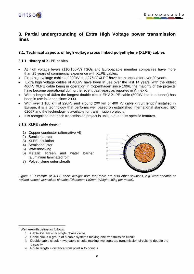
1) Copper conductor (alternative Al) 2) Semiconductor 3) XLPE insulation 4) Semiconductor 5) Waterblocking 6) Metallic screen and water barrier
(aluminium laminated foil) 7) Polyethylene outer sheath
Figure 1 : Example of XLPE cable design; note that there are also other solutions, e.g. lead sheaths or welded smooth aluminium sheaths (Diameter: 140mm; Weight: 40kg per meter). 1 We herewith define as follows:
1. Cable system = 3x single phase cable 2. Cable circuit = group of n cable systems making one transmission circuit 3. Double cable circuit = two cable circuits making two separate transmission circuits to double the
capacity 4. Route length = distance from point A to point B
7
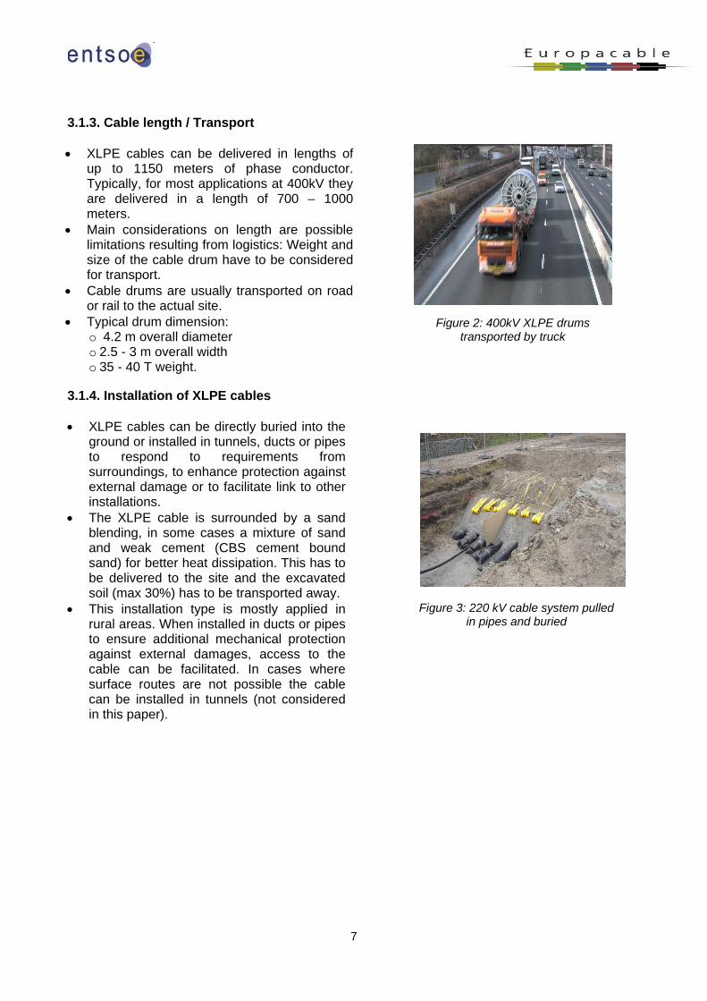
3.1.3. Cable length / Transport • XLPE cables can be delivered in lengths of
up to 1150 meters of phase conductor. Typically, for most applications at 400kV they are delivered in a length of 700 – 1000 meters.
• Main considerations on length are possible limitations resulting from logistics: Weight and size of the cable drum have to be considered for transport.
• Cable drums are usually transported on road or rail to the actual site.
• Typical drum dimension: o 4.2 m overall diameter o 2.5 - 3 m overall width o 35 - 40 T weight.
Figure 2: 400kV XLPE drums transported by truck
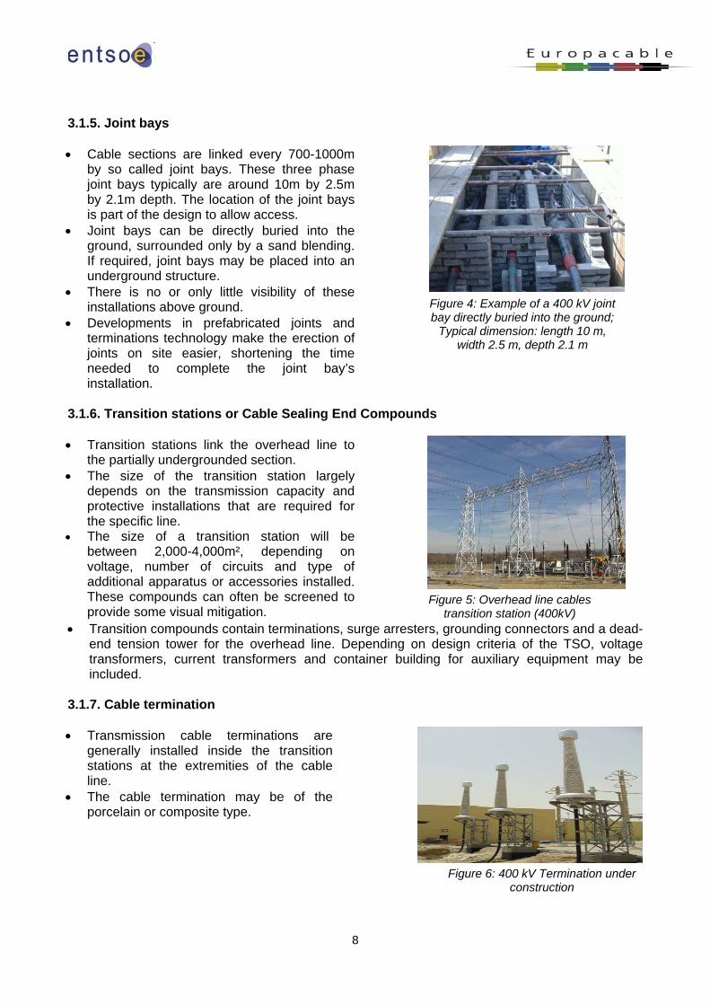
3.1.4. Installation of XLPE cables • XLPE cables can be directly buried into the
ground or installed in tunnels, ducts or pipes to respond to requirements from surroundings, to enhance protection against external damage or to facilitate link to other installations.
• The XLPE cable is surrounded by a sand blending, in some cases a mixture of sand and weak cement (CBS cement bound sand) for better heat dissipation. This has to be delivered to the site and the excavated soil (max 30%) has to be transported away.
• This installation type is mostly applied in rural areas. When installed in ducts or pipes to ensure additional mechanical protection against external damages, access to the cable can be facilitated. In cases where surface routes are not possible the cable can be installed in tunnels (not considered in this paper).
Figure 3: 220 kV cable system pulled in pipes and buried
8
3.1.5. Joint bays • Cable sections are linked every 700-1000m
by so called joint bays. These three phase joint bays typically are around 10m by 2.5m by 2.1m depth. The location of the joint bays is part of the design to allow access.
• Joint bays can be directly buried into the ground, surrounded only by a sand blending. If required, joint bays may be placed into an underground structure.
• There is no or only little visibility of these installations above ground.
• Developments in prefabricated joints and terminations technology make the erection of joints on site easier, shortening the time needed to complete the joint bay’s installation.
Figure 4: Example of a 400 kV joint bay directly buried into the ground;
Typical dimension: length 10 m, width 2.5 m, depth 2.1 m
3.1.6. Transition stations or Cable Sealing End Compounds • Transition stations link the overhead line to
the partially undergrounded section. • The size of the transition station largely
depends on the transmission capacity and protective installations that are required for the specific line.
• The size of a transition station will be between 2,000-4,000m², depending on voltage, number of circuits and type of additional apparatus or accessories installed. These compounds can often be screened to provide some visual mitigation.
Figure 5: Overhead line cables transition station (400kV)
• Transition compounds contain terminations, surge arresters, grounding connectors and a dead-end tension tower for the overhead line. Depending on design criteria of the TSO, voltage transformers, current transformers and container building for auxiliary equipment may be included.
3.1.7. Cable termination • Transmission cable terminations are
generally installed inside the transition stations at the extremities of the cable line.
• The cable termination may be of the porcelain or composite type.
Figure 6: 400 kV Termination under
construction
9
3.1.8. Norms and standards, Life expectancy • The IEC international standards 62067 require specific prequalification protocol for
transmission cable systems. This prequalification process applied for each supplier and each system consists of a 12 months test having the scope to demonstrate long term satisfactory performance of the complete cable system (cable and their accessories).
• Several bodies, in particular the IEC and the International Council on Large Electric Systems (CIGRE), facilitate the development of best practices and issue harmonized rules for fundamental principles in EHV cable technology. This ensures that industry meets a minimum level of standardization and quality.
• XLPE cables and accessories have been designed to ensure a technical life of several decades.
• Monitoring systems, both on-line and off-line, allow a continuous ‘health check’ on the cable temperature and possible partial discharges to take timely measures to ensure its longevity.
3.1.9. Time to manufacture / Production capacity • By expanding its production capacity, the cable industry is responding to the global increase in
demand for EHV XLPE insulated cables. • Today, based on an annual capacity of 120 – 140 km of phase conductor (220 kV and 400kV)
per year per line, there is the capability to produce, test, certify and install some 2,000 – 3,000 phase km of 220 and 400kV EHV cable per year (700 – 1000 km of single circuit length) including the necessary accessories and man power by European manufacturers.
Europacable believes this is sufficient capacity to meet demands in Europe for the foreseeable future. If demand for EHV XLPE cables were to increase beyond expectation, the industry is ready, as it has been in the past, to adapt capacity to meet new demand. Two to three years are necessary to build and qualify a new manufacturing line. 3.1.10. Time to install • The installation time depends on the characteristics of the cable route, the type of installation
and the civil works required. • In the case of the Turbigo-Rho line in Milano (Italy), the construction of a double cable system
8.4 km 400kV underground section along road sides took 14 months to complete2. In this case cables run along both sides of urban roads, crossing many interferences with other infrastructures and with several points in directional drilling. The soil was mainly clay mixed with gravel stones. The minimum depth of laying was 1.2 meters according to the Italian standards.
• The average installation time per km (direct buried in urban area) is 1.5 months/km for opening the trench per circuit, cable laying and closing the trench. For the cable laying alone, 1 – 2 days per km and per phase is required. Installation times indicated here refer to working with one civil work team only. By increasing the number of teams, installation times can be reduced. Also, if there are more systems in the same trench timing will only increase by approximately 10 – 20 %.
• Environmental requirements need to be taken into consideration for the installation phases.
2 CIGRE B1-302 Turbigo- Rho An example of the use of Underground XLPE cables in a meshed transmission grid, 2006
10
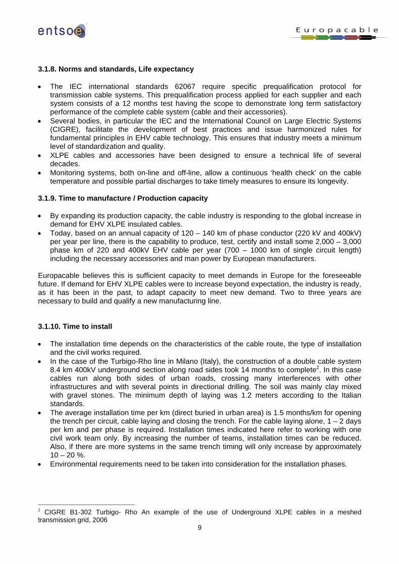
3.1.11. Time to test / commission • After the installation the cable system is
subjected to the final tests as requested by the relevant applicable standards.
• The tests after installation are composed by the AC high voltage test of the cable system main insulation and the DC test on the cable outer sheath in order to ascertain its integrity. All these tests are carried out on site using a mobile test set working at a resonance frequency between 20 and 300 Hertz. Testing in the order of 20 km is available.
• These tests have a typical duration of one week, including the preparation and the final control of the circuit arrangement, depending on the number of cables and systems to be tested according to IEC 62067.
Figure 7: Test after installation in proximity of an overhead – underground transition
compound
Additional tests can be carried out after the installation including the partial discharges on the accessories that may require approximately another week depending on the length of the circuit and the number of accessories to be tested. It should be noted that the scope of the test after installation is that to ascertain that the operations as the cable pulling, the joints and terminations mounting etc. are carried out in the proper manner and not to check the quality of the cable and the accessories that are previously 100% tested in the factory. 3.2. Integration of partial undergrounding in transmission networks Integration issues are focussed here on the two following aspects. Other considerations like switching sequences, reactive compensation, potential harmonic resonance can also be relevant for some projects. 3.2.1. Transmission capacity The cable shall be designed to carry the load flows under normal and under emergency conditions corresponding to the grid build up conditions in order to comply with the security rules deriving from the European regulations and with the specific conditions of the local grid. A typical overhead transmission line consists of two systems, each allowing the transmission of a nominal current of 3600 Amp. In order to meet the (n-1) conditions each of the two cable circuits will be loaded up to 70% (which makes 2520 Amp) in normal conditions. In case of the loss of one system the remaining one must be able transmit 3600 Amp continuously. These values correspond to base case which is studied in the chapter 4.
3.2.2. Transmission losses • The cable cross section consists mostly of single core copper conductors (sometimes
aluminium) and has usually a higher cross section compared to overhead line which uses aluminium conductors normally; however the use of bundle conductors for OHL may equalize the cross sections. However copper (UGC) has a lower resistance than aluminum (OHL); so for the same flow conditions, the level of losses in cables is lower than in overhead lines. Metallic
11
sheath losses have also to be taken into account for underground cables: these depend on cable laying configuration, type of connection of the metallic sheath (cross-bonding or not).
• A comparison of losses for OHL and UGC depends on the dimension and number of conductors and systems per transmission circuit, on needs for cooling, and reactive power compensation. Losses also vary much by the actual load on the line. Therefore the calculation of losses must be made on a case by case basis.
• However regarding partial undergrounding a cable section of few kilometres length in a transmission circuit will only originate a small part of the losses of the whole link and will not reduce the energy losses significantly.
3.3. Reliability of links with partial undergrounding 3.3.1. Reliability of cable section XLPE cable systems undergo thorough test procedures according to IEC Standards with thermal and electrical stress levels exceeding operational levels before being placed in operation. Qualified cable systems are carefully checked before delivery and commissioning: • Following production the XLPE cable and all system components undergo a thorough
verification procedure, routine tests, to confirm compliance with homogenous quality according to international standards.
• Following installation, the cable system is subject to a commissioning test to confirm proper installation.
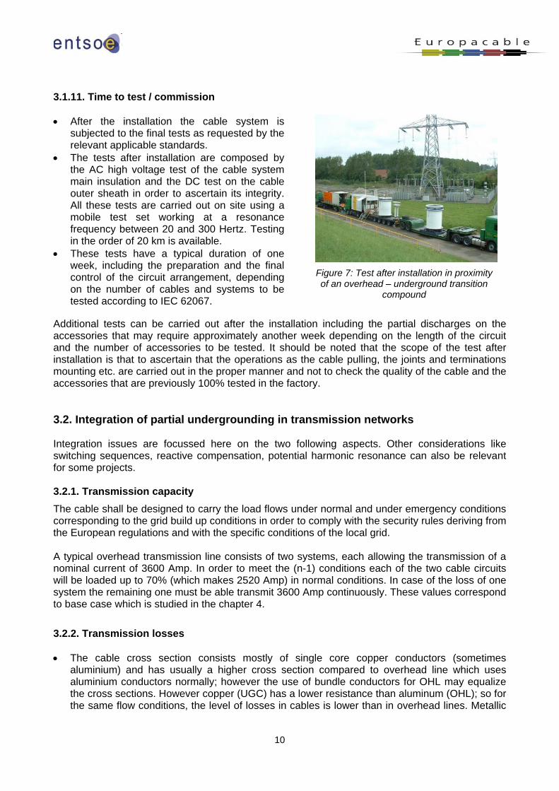
Once in the ground, the XLPE cable system is safely in place and well protected against any external weather influences. As any important infrastructure, partial undergrounding solutions shall be carefully designed to be protected against extreme weather conditions (e.g. floods, landslides, avalanches…). Monitoring systems allow close tracking of cable performance to ensure no overheating of the cable system. Figure 9 illustrates various temperature measurements. The temperature measurement is ideally carried out using an optical fibre inside the cable in the screen area. (See position 2 in Figure 9) Alternatively, the optical fibre can be positioned on the cable sheath. Positioning the fiber too far away from the cable in the surrounding soil may compromise the accuracy and should be avoided. It should only be applied on existing cable systems where no alternative is available.
Figure 8: Differences in temperature measurements
during load cycles according to the position of the sensor
Online partial discharge monitoring can be used to monitor the status of a cable system.
12
3.3.2. Failure The common reference agreed between ENTSO-E and Europacable for this paper is the Cigre Technical brochure 379 “Update of Service Experience of HV Underground Cable Systems”3. This paper reports the fault on land cables over the period 2000 – 2005 for land cable systems according to voltage classes (60 to 219kV and 220 to 500kV). In this brochure a failure is defined as “Any occurrence on a cable system which requires the circuit to be de-energized”, i.e. a failure is counted irrespective of the reason or length of outage time. This has to be taken into account comparing this study with other failure statistics. The Cigre Study is based on data from the period 2000 – 2005. Since then, a significant number of new 400kV cable systems has been installed in Europe (see Annex 6). The operational experience of these systems is not taken into account in the study. Therefore it is agreed that it would be useful to update the Cigre data in the near future. Once in operation, the cable is protected by the surrounding soil. However as confirmed by the Cigre Technical brochure, external damages (e.g. other construction works) contribute to 50% of cable system failures. As direct buried cable systems are more exposed to damage by external interventions than cable systems installed in ducts or tunnels, installation in ducts or tunnels as an appropriate mitigation measure may be considered. However it is to be noted that repair time of cable buried in ducts are longer than for cables directly buried. Concerning workmanship the following statement on internal faults is given in the study: “Within the data there are examples (approx 50%) of cases where inadequate jointer training gives rise to a significant number of failures”. Taking into account the failure rates for EHV cables and accessories of the Cigre Technical brochure failure rates for a defined cable system can be estimated. Assuming a partial undergrounding of 10 km with single cable lengths of 1000m and based on the failure rate of a single cable system 0.0307 failures per year, the time between failures can be estimated at 33 years. When the circuit is made of two cable systems the time between failures of the circuit can be estimated at 16 years. Fault location is carried out using a standard procedure for locating cable and accessories failures. 3.3.3. Repair time According to Cigre Technical brochure 379, more than one third of the cable faults in EHV cable systems were repaired and the cable system was re-energized again within one week and more than 75% within one month. This includes fault location, repair and testing. (Note that outage times less than 1 day and longer than 6 months were not considered in the survey) “The 13% of AC-extruded cables which took more than 3 months for repair is probably due to a very low priority given to this repair” (Cigre Technical brochure 379). Operational constraints may however have contributed sometimes to such a delay between repair and re-commissioning. Down times are affected by: • Safe access to site • Clarification time required for TSOs and, if required, independent experts to undertake a
thorough investigation to assess the reasons behind a failure; in exceptional circumstances this can last several months
• Decisions on counter measures to prevent future failures
3 CIGRE 379 Update of Service Experience of HV Underground and Cable Systems, April 2009
13
• Availability / ordering / delivering of spare parts (recommended to hold stock) • Repairs and testing itself can be conducted in less than 3 weeks. 3.3.4. Consequences for TSOs at the planning stage As any transmission link, also partial undergrounding requires a risk assessment of integrating the link into the system. This includes: • a check on whether it is acceptable regarding the system operation especially long duration
outage, • identification of mitigating measures which would have to be implemented in an outage
situation and • any measure (from the design phase to the operation and maintenance conditions) to reduce
the risk of outages. 3.3.5. Autoreclosure functionality This functionality is used for overhead transmission lines; it allows to reenergize the line just after a fault and to face the fugitive faults (which represent the majority of faults affecting overhead lines) without any disturbance in the power system. Since any failure on the cable section is permanent, autoreclosure is not applicable on this section. In order to maintain this functionality specific protection and measurement equipments should be used which will make possible a precise localisation of the fault, to identify which one of the cable or the overhead line section is affected and to initiate the adequate remedial action. 3.4. Environmental aspects of partial undergrounding 3.4.1. Environmental impacts during operation 3.4.1.1. Trench width in directly buried cables • Width required depends on the number of cables, which in turn depends mainly
o on the desired transmission capacity o on the general geology of the soil o on existing surrounding structures (undercrossing roads, highways, rails roads, rivers or
waterways) o on the thermal resistivity of the refilled soil material in the trench o on other cable systems adjacent to the new ones o on space available o on the thermal mutual influence
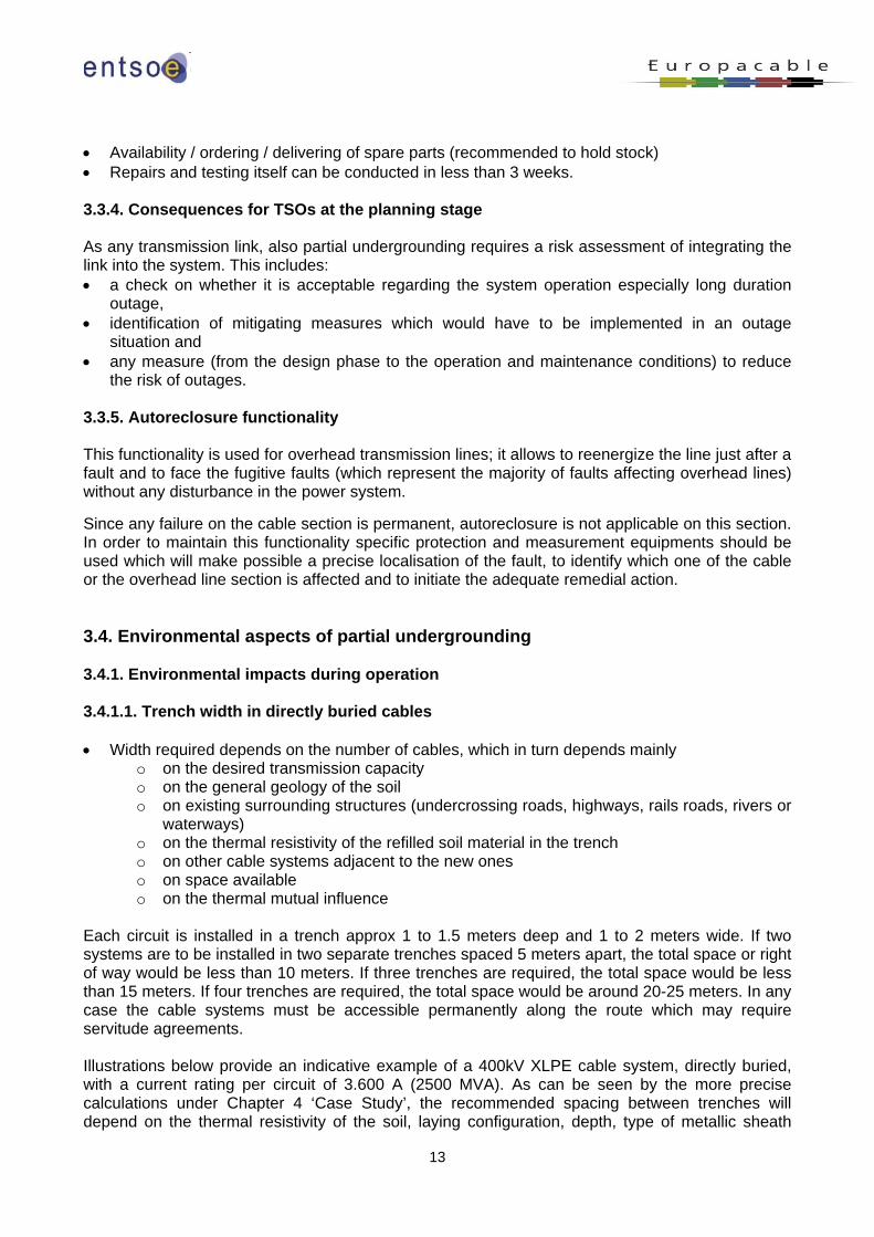
Each circuit is installed in a trench approx 1 to 1.5 meters deep and 1 to 2 meters wide. If two systems are to be installed in two separate trenches spaced 5 meters apart, the total space or right of way would be less than 10 meters. If three trenches are required, the total space would be less than 15 meters. If four trenches are required, the total space would be around 20-25 meters. In any case the cable systems must be accessible permanently along the route which may require servitude agreements. Illustrations below provide an indicative example of a 400kV XLPE cable system, directly buried, with a current rating per circuit of 3.600 A (2500 MVA). As can be seen by the more precise calculations under Chapter 4 ‘Case Study’, the recommended spacing between trenches will depend on the thermal resistivity of the soil, laying configuration, depth, type of metallic sheath
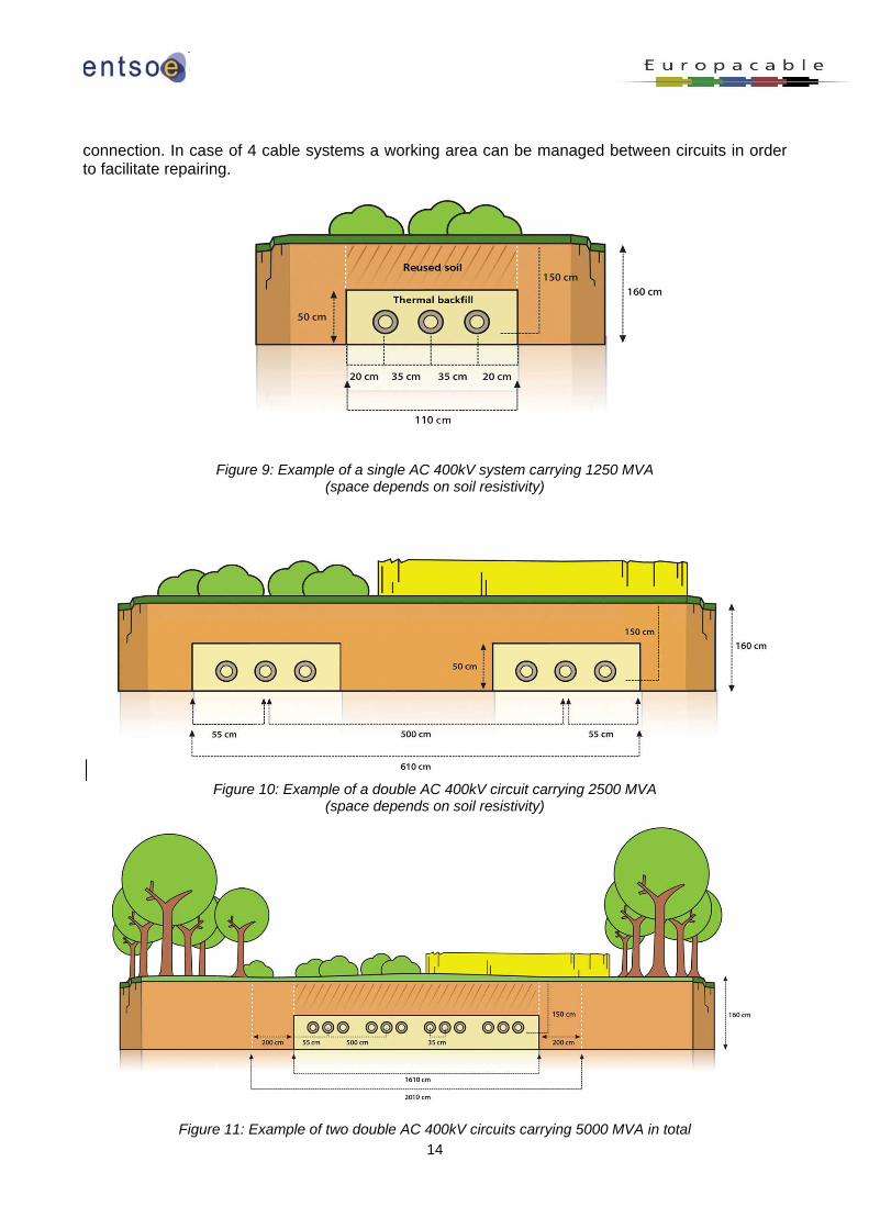
14
connection. In case of 4 cable systems a working area can be managed between circuits in order to facilitate repairing.
Figure 9: Example of a single AC 400kV system carrying 1250 MVA
(space depends on soil resistivity)
Figure 10: Example of a double AC 400kV circuit carrying 2500 MVA
(space depends on soil resistivity)
Figure 11: Example of two double AC 400kV circuits carrying 5000 MVA in total
15
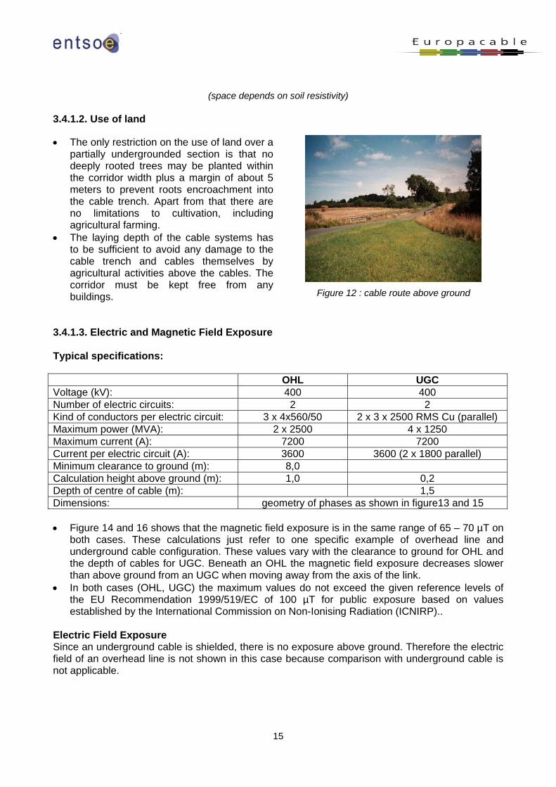
(space depends on soil resistivity) 3.4.1.2. Use of land • The only restriction on the use of land over a
partially undergrounded section is that no deeply rooted trees may be planted within the corridor width plus a margin of about 5 meters to prevent roots encroachment into the cable trench. Apart from that there are no limitations to cultivation, including agricultural farming.
• The laying depth of the cable systems has to be sufficient to avoid any damage to the cable trench and cables themselves by agricultural activities above the cables. The corridor must be kept free from any buildings.
Figure 12 : cable route above ground
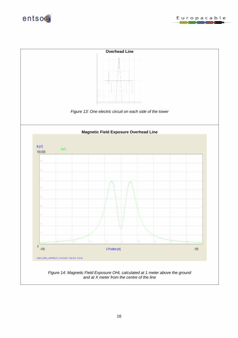
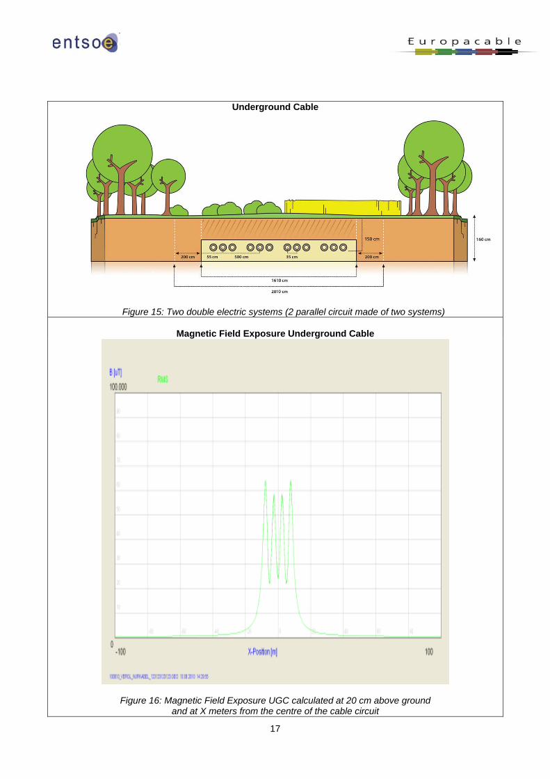
3.4.1.3. Electric and Magnetic Field Exposure Typical specifications: OHL UGC Voltage (kV): 400 400 Number of electric circuits: 2 2 Kind of conductors per electric circuit: 3 x 4x560/50 2 x 3 x 2500 RMS Cu (parallel) Maximum power (MVA): 2 x 2500 4 x 1250 Maximum current (A): 7200 7200 Current per electric circuit (A): 3600 3600 (2 x 1800 parallel) Minimum clearance to ground (m): 8,0 Calculation height above ground (m): 1,0 0,2 Depth of centre of cable (m): 1,5 Dimensions: geometry of phases as shown in figure13 and 15 • Figure 14 and 16 shows that the magnetic field exposure is in the same range of 65 – 70 µT on
both cases. These calculations just refer to one specific example of overhead line and underground cable configuration. These values vary with the clearance to ground for OHL and the depth of cables for UGC. Beneath an OHL the magnetic field exposure decreases slower than above ground from an UGC when moving away from the axis of the link.
• In both cases (OHL, UGC) the maximum values do not exceed the given reference levels of the EU Recommendation 1999/519/EC of 100 µT for public exposure based on values established by the International Commission on Non-Ionising Radiation (ICNIRP)..
Electric Field Exposure Since an underground cable is shielded, there is no exposure above ground. Therefore the electric field of an overhead line is not shown in this case because comparison with underground cable is not applicable.
16
Overhead Line
Figure 13: One electric circuit on each side of the tower
Magnetic Field Exposure Overhead Line
Figure 14: Magnetic Field Exposure OHL calculated at 1 meter above the ground and at X meter from the centre of the line
17
Underground Cable
Figure 15: Two double electric systems (2 parallel circuit made of two systems)
Magnetic Field Exposure Underground Cable
Figure 16: Magnetic Field Exposure UGC calculated at 20 cm above ground and at X meters from the centre of the cable circuit
18
3.4.1.4. Possible heating of ground • During operation, the temperature of the cable will rise dependent on the current carried and
load factor. Heat distribution to surrounding soil depends on the backfill material. • The impact of heat release on soil temperature is strictly local and very limited. • It is only under long term full load conditions that soil directly over the trench may heat up by
approximately 2° Celsius – in partial load operations this value is lower. • If necessary, the thermal impact may be additionally mitigated with the use of a cable with a
larger conductor size if possible. 3.4.2. Environmental impacts during installation • Civil works required to partially underground a high
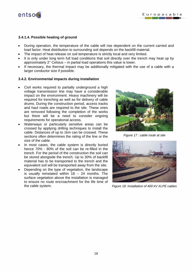
voltage transmission line may have a considerable impact on the environment. Heavy machinery will be required for trenching as well as for delivery of cable drums. During the construction period, access tracks and haul roads are required to the site. These ones are removed following the completion of the works but there will be a need to consider ongoing requirements for operational access.
• Waterways or particularly sensitive areas can be crossed by applying drilling techniques to install the cable. Distances of up to 1km can be crossed. These sections often determines the rating of the line or the size of the cable.
• In most cases, the cable system is directly buried hence 70% - 80% of the soil can be re-filled in the trench. For the period of the construction the soil can be stored alongside the trench. Up to 30% of backfill material has to be transported to the trench and the equivalent soil will be transported away from the site.
• Depending on the type of vegetation, the landscape is usually reinstated within 18 – 24 months. The surface vegetation above the installation is managed to ensure no route encroachment for the life time of the cable system.
Figure 17 : cable route at site
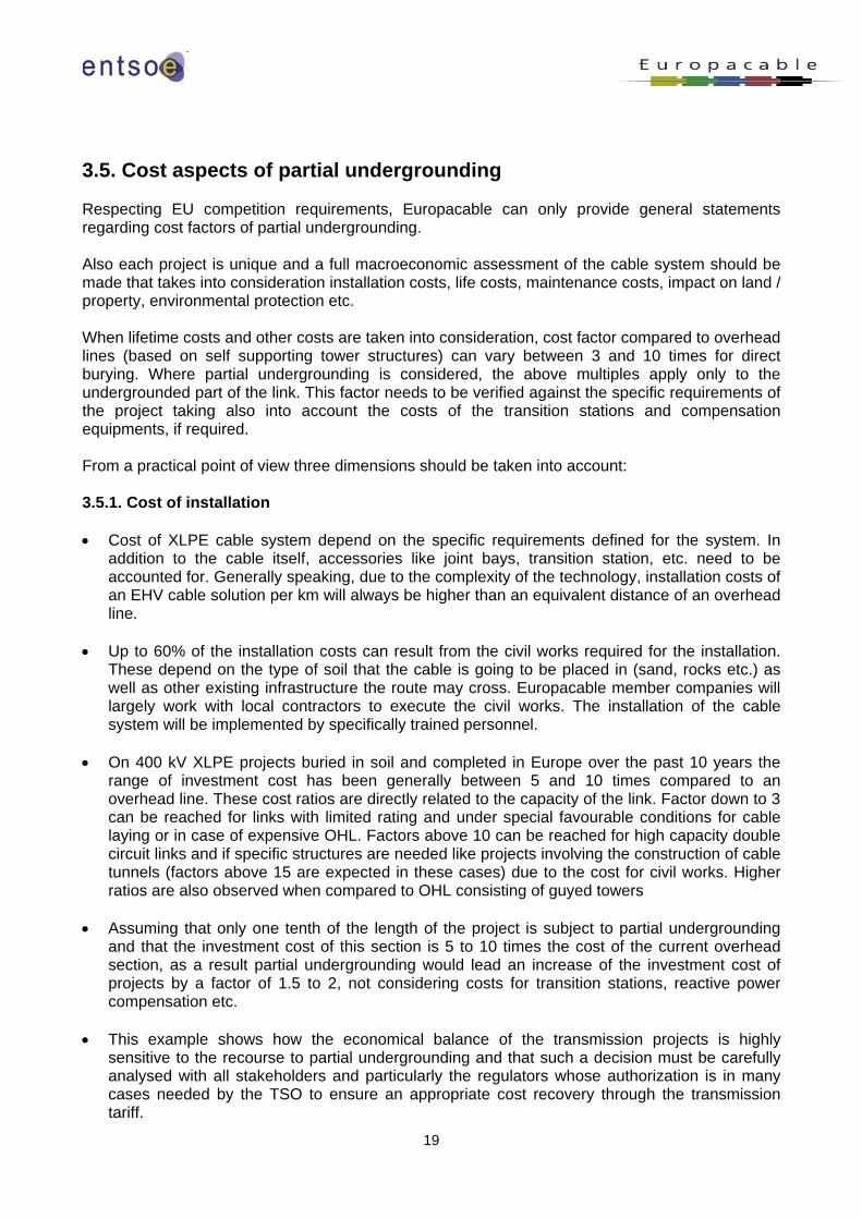
Figure 18: Installation of 400 kV XLPE cables
19
3.5. Cost aspects of partial undergrounding Respecting EU competition requirements, Europacable can only provide general statements regarding cost factors of partial undergrounding. Also each project is unique and a full macroeconomic assessment of the cable system should be made that takes into consideration installation costs, life costs, maintenance costs, impact on land / property, environmental protection etc.
When lifetime costs and other costs are taken into consideration, cost factor compared to overhead lines (based on self supporting tower structures) can vary between 3 and 10 times for direct burying. Where partial undergrounding is considered, the above multiples apply only to the undergrounded part of the link. This factor needs to be verified against the specific requirements of the project taking also into account the costs of the transition stations and compensation equipments, if required. From a practical point of view three dimensions should be taken into account: 3.5.1. Cost of installation • Cost of XLPE cable system depend on the specific requirements defined for the system. In
addition to the cable itself, accessories like joint bays, transition station, etc. need to be accounted for. Generally speaking, due to the complexity of the technology, installation costs of an EHV cable solution per km will always be higher than an equivalent distance of an overhead line.
• Up to 60% of the installation costs can result from the civil works required for the installation.
These depend on the type of soil that the cable is going to be placed in (sand, rocks etc.) as well as other existing infrastructure the route may cross. Europacable member companies will largely work with local contractors to execute the civil works. The installation of the cable system will be implemented by specifically trained personnel.
• On 400 kV XLPE projects buried in soil and completed in Europe over the past 10 years the
range of investment cost has been generally between 5 and 10 times compared to an overhead line. These cost ratios are directly related to the capacity of the link. Factor down to 3 can be reached for links with limited rating and under special favourable conditions for cable laying or in case of expensive OHL. Factors above 10 can be reached for high capacity double circuit links and if specific structures are needed like projects involving the construction of cable tunnels (factors above 15 are expected in these cases) due to the cost for civil works. Higher ratios are also observed when compared to OHL consisting of guyed towers
• Assuming that only one tenth of the length of the project is subject to partial undergrounding and that the investment cost of this section is 5 to 10 times the cost of the current overhead section, as a result partial undergrounding would lead an increase of the investment cost of projects by a factor of 1.5 to 2, not considering costs for transition stations, reactive power compensation etc.
• This example shows how the economical balance of the transmission projects is highly sensitive to the recourse to partial undergrounding and that such a decision must be carefully analysed with all stakeholders and particularly the regulators whose authorization is in many cases needed by the TSO to ensure an appropriate cost recovery through the transmission tariff.
20
3.5.2. Cost of operation The health and safety regulation of the TSO requires operational activities which do not differ in costs too much from the operational expenses of the 400 kV overhead lines. Once in operation, a cable system itself is nearly maintenance free. Monitoring systems allow partial discharge surveillance. As any transmission corridor, the cable route requires regular inspection to prevent any encroachment. In some countries, the corrosion protection test with 5 kV dc voltage for the outer sheath has to be performed at least every second year. As previously mentioned, as the UGC section represents only a limited part of the total length of the link, it will not significantly affect the volume of operational expenditures generated by the whole link. The maintenance of the line/cable transition stations is of the same nature as for EHV substations.
21
4. Case Study This case study aims at providing more detailed figures concerning the design of an underground section in a typical overhead transmission line. 4.1. Technical specifications A 400 kV XLPE cable system directly buried in trench connecting 2 substations with the following specifications: • Sequence: Substation – 35 km OHL – 7.5km UGC – 15km OHL – Substation • Reference nominal voltage: 360-420 kV, 400 kV for calculations • Maximum system voltage for one hour: 440 kV • Minimum voltage for one hour: 350 kV • Current rating: 3600 A • Short circuit rating: 63 kA for 1 second • Soil thermal resistivity: 0.8, 1.0, 1.5 K.m/W • Operational conditions Case study: • In case 1 when two circuits are available each one must transmit up to 70 % (which makes 2 x
2520 A) in order to comply with N-1 conditions (outage of the second circuit of the line); when only one circuit is available it must transmit 3600 A continuously
• In case 2 in addition to the above conditions a emergency load of 3600 A must be transmitted simultaneously in each of the two for a duration of 70 hours. This situation can result from the outage of another link in the grid.
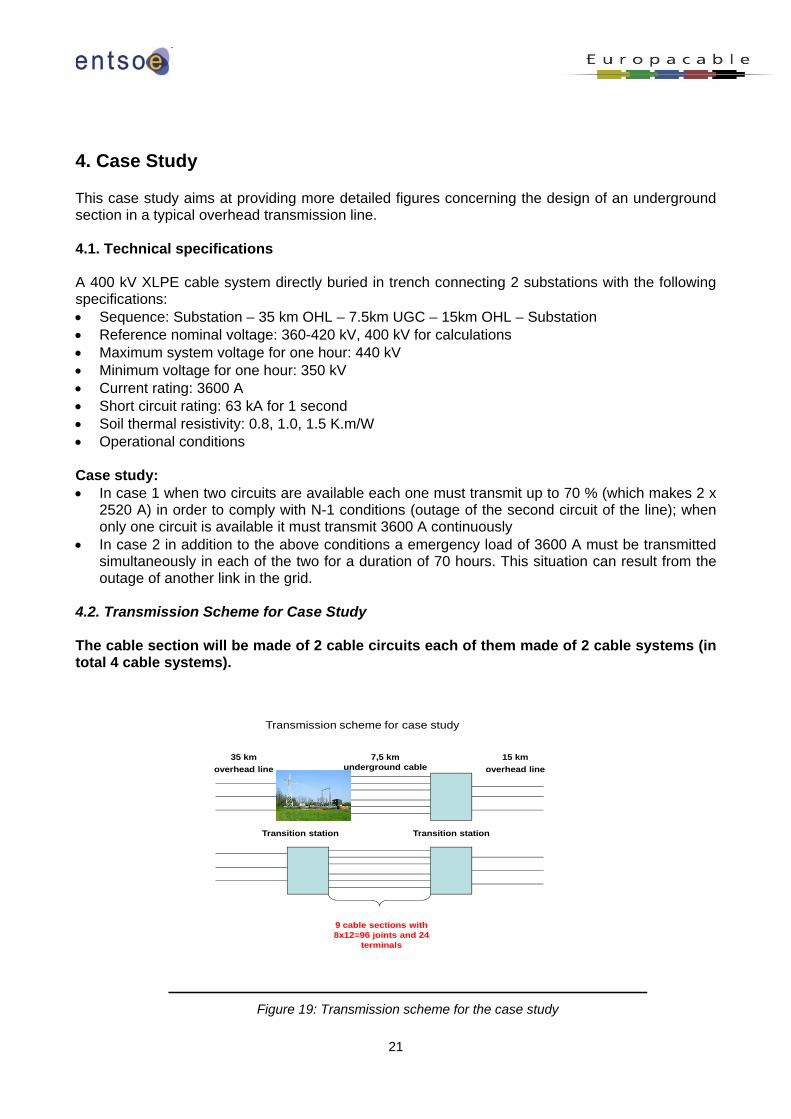
4.2. Transmission Scheme for Case Study The cable section will be made of 2 cable circuits each of them made of 2 cable systems (in total 4 cable systems).
Transmission scheme for case study
35 km overhead line
7,5 km underground cable
15 km overhead line
Transition station Transition station
9 cable sections with 8x12=96 joints and 24
terminals
Figure 19: Transmission scheme for the case study
22
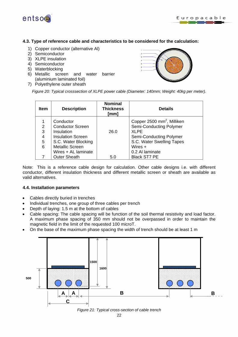
4.3. Type of reference cable and characteristics to be considered for the calculation: 1) Copper conductor (alternative Al) 2) Semiconductor 3) XLPE insulation 4) Semiconductor 5) Waterblocking 6) Metallic screen and water barrier
(aluminium laminated foil) 7) Polyethylene outer sheath
Figure 20: Typical crosssection of XLPE power cable (Diameter: 140mm; Weight: 40kg per meter).
Item Description Nominal
Thickness [mm]
Details
1 2 3 4 5 6
7
Conductor Conductor Screen Insulation Insulation Screen S.C. Water Blocking Metallic Screen Wires + AL laminate Outer Sheath
26.0
5.0
Copper 2500 mm2, Milliken Semi-Conducting Polymer XLPE Semi-Conducting Polymer S.C. Water Swelling Tapes Wires + 0.2 Al laminate Black ST7 PE
Note: This is a reference cable design for calculation. Other cable designs i.e. with different conductor, different insulation thickness and different metallic screen or sheath are available as valid alternatives. 4.4. Installation parameters • Cables directly buried in trenches • Individual trenches, one group of three cables per trench • Depth of laying: 1.5 m at the bottom of cables • Cable spacing: The cable spacing will be function of the soil thermal resistivity and load factor.
A maximum phase spacing of 350 mm should not be overpassed in order to maintain the magnetic field in the limit of the requested 100 microT.
• On the base of the maximum phase spacing the width of trench should be at least 1 m
Figure 21: Typical cross-section of cable trench
1600
1500
A BC
A B
500
23
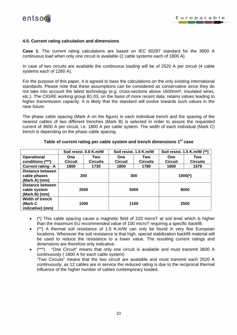
4.5. Current rating calculation and dimensions Case 1: The current rating calculations are based on IEC 60287 standard for the 3600 A continuous load when only one circuit is available (2 cable systems each of 1800 A). In case of two circuits are available the continuous loading will be of 2520 A per circuit (4 cable systems each of 1260 A). For the purpose of this paper, it is agreed to base the calculations on the only existing international standards. Please note that these assumptions can be considered as conservative since they do not take into account the latest technology (e.g. cross-sections above 1600mm², insulated wires, etc.). The CIGRE working group B1.03, on the basis of more recent data, retains values leading to higher transmission capacity. It is likely that the standard will evolve towards such values in the near future. The phase cable spacing (Mark A on the figure) in each individual trench and the spacing of the nearest cables of two different trenches (Mark B) is selected in order to assure the requested current of 3600 A per circuit, i.e. 1800 A per cable system. The width of each individual (Mark C) trench is depending on the phase cable spacing.
Table of current rating per cable system and trench dimensions 1st case Soil resist. 0.8 K.m/W Soil resist. 1.0 K.m/W Soil resist. 1.5 K.m/W (**) Operational conditions (***)
One Circuit
Two Circuits
One Circuit
Two Circuits
One Circuit
Two Circuits
Current rating - A 1800 1730 1800 1780 1800 1579 Distance between cable phases (Mark A) (mm)
200
300
1000(*)
Distance between cable system (Mark B) (mm)
2500
5000
8000
Width of trench (Mark C indicative) (mm)
1000
1100
2500
• (*) This cable spacing cause a magnetic field of 220 microT at soil level which is higher than the maximum EU recommended value of 100 microT requiring a specific backfill.
• (**) A thermal soil resistance of 1.5 K.m/W can only be found in very few European locations. Whenever the soil resistance is that high, special stabilization backfill material will be used to reduce the resistance to a lower value. The resulting current ratings and dimensions are therefore only indicative.
• (***) “One Circuit” means that only one circuit is available and must transmit 3600 A continuously ( 1800 A for each cable system) “Two Circuits” means that the two circuit are available and must transmit each 2520 A continuously; as 12 cables are in service the reduced rating is due to the reciprocal thermal influence of the higher number of cables contemporary loaded.
24
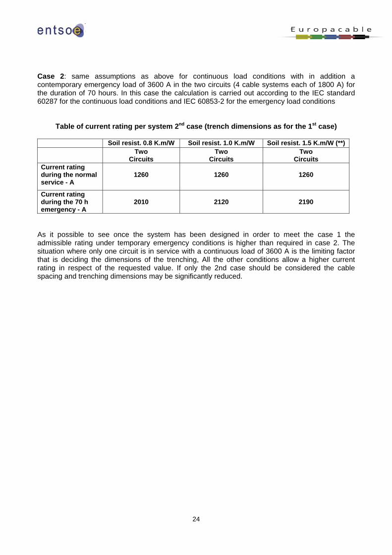
Case 2: same assumptions as above for continuous load conditions with in addition a contemporary emergency load of 3600 A in the two circuits (4 cable systems each of 1800 A) for the duration of 70 hours. In this case the calculation is carried out according to the IEC standard 60287 for the continuous load conditions and IEC 60853-2 for the emergency load conditions
Table of current rating per system 2nd case (trench dimensions as for the 1st case)
Soil resist. 0.8 K.m/W Soil resist. 1.0 K.m/W Soil resist. 1.5 K.m/W (**) Two
Circuits Two
Circuits Two
Circuits Current rating during the normal service - A
1260
1260
1260
Current rating during the 70 h emergency - A
2010
2120
2190
As it possible to see once the system has been designed in order to meet the case 1 the admissible rating under temporary emergency conditions is higher than required in case 2. The situation where only one circuit is in service with a continuous load of 3600 A is the limiting factor that is deciding the dimensions of the trenching, All the other conditions allow a higher current rating in respect of the requested value. If only the 2nd case should be considered the cable spacing and trenching dimensions may be significantly reduced.
25
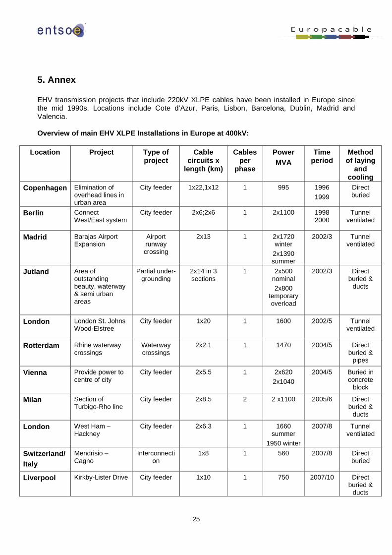
5. Annex EHV transmission projects that include 220kV XLPE cables have been installed in Europe since the mid 1990s. Locations include Cote d’Azur, Paris, Lisbon, Barcelona, Dublin, Madrid and Valencia. Overview of main EHV XLPE Installations in Europe at 400kV:
Location Project Type of project
Cable circuits x
length (km)
Cables per
phase
Power MVA
Time period
Method of laying
and cooling
Copenhagen Elimination of overhead lines in urban area
City feeder 1x22,1x12 1 995
1996 1999
Direct buried
Berlin Connect West/East system
City feeder 2x6;2x6 1 2x1100 1998 2000
Tunnel ventilated
Madrid Barajas Airport Expansion
Airport runway crossing
2x13 1 2x1720 winter
2x1390 summer
2002/3 Tunnel ventilated
Jutland Area of outstanding beauty, waterway & semi urban areas
Partial under-grounding
2x14 in 3 sections
1 2x500 nominal 2x800
temporary overload
2002/3 Direct buried &
ducts
London London St. Johns Wood-Elstree
City feeder 1x20 1 1600 2002/5 Tunnel ventilated
Rotterdam Rhine waterway crossings
Waterway crossings
2x2.1 1 1470 2004/5 Direct buried &
pipes
Vienna Provide power to centre of city
City feeder 2x5.5 1 2x620 2x1040
2004/5 Buried in concrete
block
Milan Section of Turbigo-Rho line
City feeder
2x8.5 2 2 x1100 2005/6 Direct buried &
ducts
London West Ham – Hackney
City feeder 2x6.3 1 1660 summer
1950 winter
2007/8 Tunnel ventilated
Switzerland/ Italy
Mendrisio – Cagno
Interconnection
1x8 1 560 2007/8 Direct buried
Liverpool Kirkby-Lister Drive City feeder 1x10 1 750 2007/10 Direct buried &
ducts

26
For further information please contact: Jean Verseille Thomas Neesen Chairman of ENTSO-E Secretary General Europacable System Development Committee Email: [email protected] Email: [email protected] http://www.entsoe.eu http://www.europacable.eu