Embed Size (px)
Citation preview
+
Fortinet NGFW with Gigamon Inline Deployment Guide
Version 1.0

COPYRIGHT Copyright © 2017 Gigamon. All Rights Reserved. No part of this publication may be reproduced, transmitted, transcribed, stored in a retrieval system, or translated into any language in any form or by any means without Gigamon’s written permission.
TRADEMARK ATTRIBUTIONS Copyright © 2017 Gigamon. All rights reserved. Gigamon and the Gigamon logo are trademarks of Gigamon in the United States and/or other countries. Gigamon trademarks can be found at www.gigamon.com/legal- trademarks. All other trademarks are the trademarks of their respective owners.

FortiGate NGFW with Gigamon Deployment Guide 3 + FortiGate NGFW with Gigamon Deployment Guide 3
+ FortiGate NGFW with Gigamon Deployment Guide 3
+ FortiGate NGFW with Gigamon Deployment Guide 3
+
Table of Contents Overview ................................................................................................................................................................. 5
Solution Overview .......................................................................................................................................................... 6
Use Case: Inline Bypass (Virtual Wire Pair) Mode ........................................................................................................ 6
Deployment Prerequisites ............................................................................................................................................... 6
Architecture Overview .................................................................................................................................................... 6
Access Credentials .......................................................................................................................................................... 7
Configurations......................................................................................................................................................... 8
Configuring FortiGate NGFW: Virtual Wire Pair .......................................................................................................... 9
Configuring FortiGate Virtual Wire Pair ......................................................................................................................... 9
Configuring GigaVUE-HC2: Inline Network and Inline Tool Groups ......................................................................... 10
Configuring the GigaVUE-HC2 Inline Network and Inline Tools ................................................................................. 11
Testing the Functionality of the FortiGate NGFWs ...................................................................................................... 19
Summary and Conclusions ................................................................................................................................... 21
Available Documentation ..................................................................................................................................... 21
Documentation Feedback ...................................................................................................................................... 21
Contacting Gigamon Support ............................................................................................................................... 21
Contacting Fortinet Support .................................................................................................................................. 21


FortiGate NGFW with Gigamon Deployment Guide 5 + FortiGate NGFW with Gigamon Deployment Guide 5
+ FortiGate NGFW with Gigamon Deployment Guide 5
+ FortiGate NGFW with Gigamon Deployment Guide 5
+
Overview Fortinet’s award-winning next-generation firewalls (NGFWs) provide high-performance, consolidated security for end-to-end protection across the entire network. Through awareness of applications, users, and content within network traffic, FortiGate NGFWs offer comprehensive protection against known and unknown threats (e.g., ransomware, malicious botnets, zero-day, and encrypted malware). They offer scalable throughput of advanced security services, flexible network interfaces, and performance based on Fortinet’s powerful security processors. The FortiOS operating system ensures superior price, performance, and security efficacy.
The GigaVUE-HC2 Series is part of the GigaSECURE® Security Delivery Platform from Gigamon. The GigaBPS module in the GigaVUE-HC2 Series provides bypass protection to the Fortinet 3020 NGFWs. The module leverages two levels of bypass protection: physical and logical. Physical bypass preserves network traffic, failing to wire in the event of a power outage. Logical bypass protects against inline tool failures that could disrupt network traffic. Bidirectional heartbeats monitor the health of the inline tool and in the event of a loss of link or loss of heartbeat the Gigamon-HC2 can bypass traffic around the failing tool. Alternatively, the Gigamon-HC2 can bring down the network link so that the traffic can be routed to a redundant network path. GigaBPS pertains specifically to fiber links. For copper bypass, Gigamon offers a GigaVUE-HC2 copper TAP module. This module includes electrical relays that can be used for bypass protection.
Aside from the above, deploying FortiGate and Gigamon together has the following benefits:
Traffic distribution for load sharing
Improves the scalability of inline security by distributing the traffic across multiple FortiGate NGFW appliances, allowing them to share the load and inspect more traffic.
Agile deployment
Adds, removes, and/or upgrades FortiGate NGFW appliances without disrupting network traffic; converting FortiGate NGFW appliances from out-of-band monitoring to inline inspection on the fly without rewiring.

6 Gigamon Inc.
Solution Overview The solution tested and described in this guide is based on a standard active inline network and tool deployment where two or more Fortinet appliances are directly cabled to one GigaVUE-HC2 chassis. The solution was tested with one GigaVUE-HC2 visibility node, one GigaVUE-FM Fabric Manager, and a FortiGate appliance.
This section covers the following:
Use Case
Deployment Prerequisites
Architecture Overview
Access Credentials
Use Case: Inline Bypass (Virtual Wire Pair) Mode Customers may need multiple FortiGate NGFW appliances to scale to the volume of traffic generated on their network. When the aggregate traffic exceeds the capacity of any single FortiGate NGFW, you must deploy multiple NGFWs with the ability to select traffic of interest, while bypassing the rest, and then distributing the selected traffic of interest among two or more NGFWs.
This distribution ensures all packets in a given TCP/UDP session go to the same group member. It also ensures that if any member of the group goes offline for any reason, the Gigamon-HC2 will distribute traffic amongst the remaining members, thereby ensuring availability of the security functions provided by the Fortinet NGFW.
Gigamon also gives the ability to test the configuration in an out-of-band mode called bypass with monitoring to allow complete confidence before going live. Switching from out-of-band to in-band is done by changing the setting in the inline network link, eliminating the need for physical change control procedures.
Deployment Prerequisites The Gigamon plus Fortinet Next Generation Firewall (NGFW) solution consists of the following:
GigaVUE-HC2 chassis with GigaVUE-OS 5.0.00 software, one PRT-HC0-X24, and one TAP-HC0-G100C0 (a BPS-HC0 line card can also be used).
GigaVUE-FM version 5.0 software for GigaVUE-HC2 GUI configuration
Two FortiGate NGFW appliance. This includes the following:
FortiOS version 5.4.5
NOTE: This guide assumes all appliances are fully licensed for all features used, management network interfaces have been configured, and an account with sufficient admin privileges is used.
Architecture Overview This section presents the combined solution using a GigaVUE-HC2 inline bypass module with a FortiGate NGFW appliance. The reference architecture in Figure 1-1 shows each component’s position in the overall network infrastructure, where all network components and inline security tools are connected directly to the GigaVUE-HC2.
FortiGate NGFW with Gigamon Deployment Guide 7 + FortiGate NGFW with Gigamon Deployment Guide 7
+
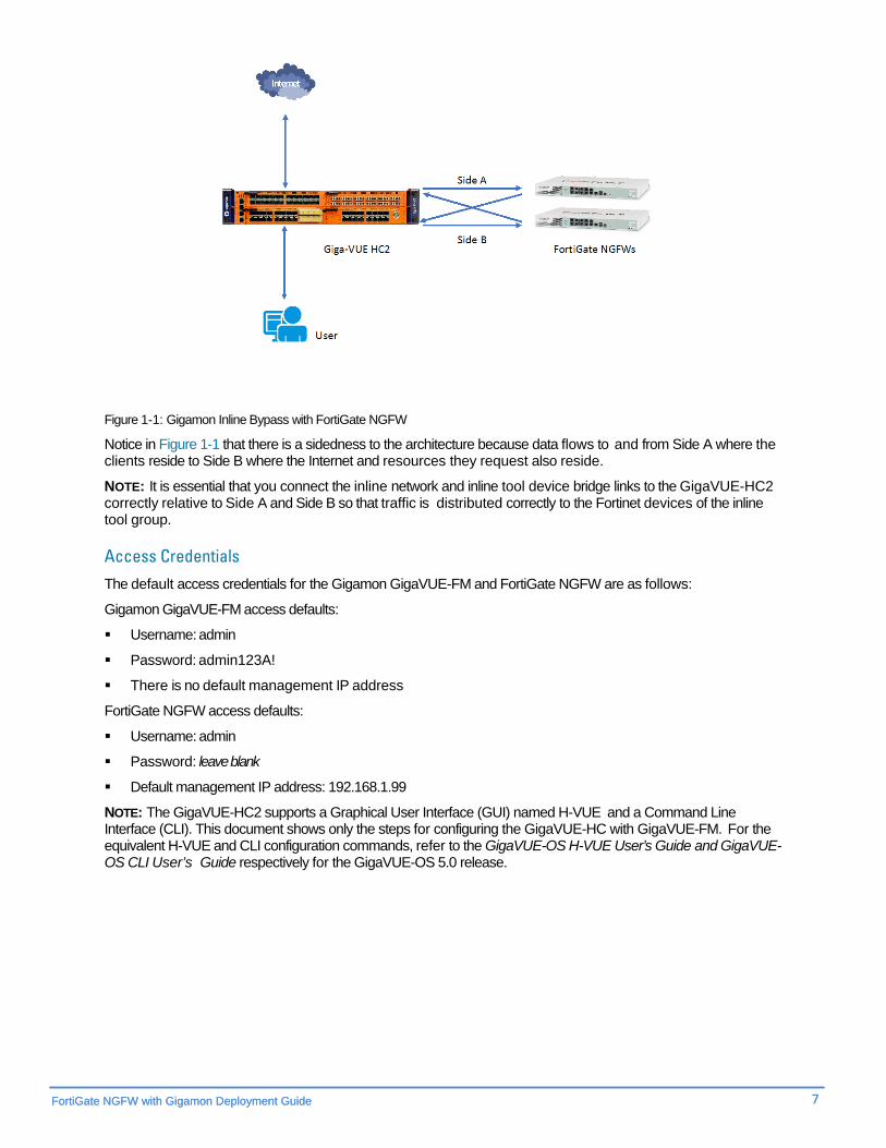
Figure 1-1: Gigamon Inline Bypass with FortiGate NGFW
Notice in Figure 1-1 that there is a sidedness to the architecture because data flows to and from Side A where the clients reside to Side B where the Internet and resources they request also reside.
NOTE: It is essential that you connect the inline network and inline tool device bridge links to the GigaVUE-HC2 correctly relative to Side A and Side B so that traffic is distributed correctly to the Fortinet devices of the inline tool group.
Access Credentials The default access credentials for the Gigamon GigaVUE-FM and FortiGate NGFW are as follows:
Gigamon GigaVUE-FM access defaults:
Username: admin
Password: admin123A!
There is no default management IP address
FortiGate NGFW access defaults:
Username: admin
Password: leave blank
Default management IP address: 192.168.1.99
NOTE: The GigaVUE-HC2 supports a Graphical User Interface (GUI) named H-VUE and a Command Line Interface (CLI). This document shows only the steps for configuring the GigaVUE-HC with GigaVUE-FM. For the equivalent H-VUE and CLI configuration commands, refer to the GigaVUE-OS H-VUE User’s Guide and GigaVUE-OS CLI User’s Guide respectively for the GigaVUE-OS 5.0 release.
8 Gigamon Inc.
Configurations This chapter describes the configuration procedures for the GigaVUE-HC2 and FortiGate NGFW as an inline tool group solution through Gigamon’s GigaVUE-FM. The procedures are organized as follows:
• FortiGate Configuration: Virtual Wire Pair
• Gigamon GigaVUE-HC2 Configuration: Inline Networks and Inline Tool Groups
The procedures configure the GigaVUE-HC2 to send live traffic to the FortiGate inline tool group, which will allow the use of FortiGate’s NGFW protection capabilities.
Per best practices guidelines from FortiGate, the Gigamon GigaVUE-HC2 will be configured to distribute the traffic to the two Fortinet appliances in the inline tool group, assuring all traffic for any given client (by IP address) goes to the same member of the Fortinet inline tool group.
NOTE: This chapter assumes that you have connected the Fortinet appliances directly to GigaVUE-HC2 as shown in Figure 1-1. You should configure all GigaVUE-HC2 ports that connects the Fortinet appliances as port type Inline Tool. Furthermore, you should configure the GigaVUE-HC2 inline bypass ports connected to the network devices as Inline Network ports. For specific instructions on how to complete these tasks, refer to the User Guides and Technical Documentation in the Customer Portal.
NOTE: This chapter describes how to configure the FortiGate NGFW in NAT Mode using Virtual Wire Pairs. The FortiGate NGFW could instead be configured in Transparent Mode if needed.
FortiGate NGFW with Gigamon Deployment Guide 9 + FortiGate NGFW with Gigamon Deployment Guide 9
+
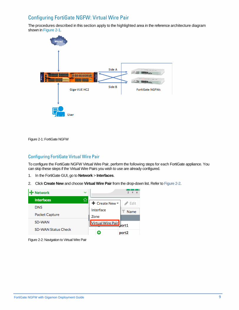
Configuring FortiGate NGFW: Virtual Wire Pair The procedures described in this section apply to the highlighted area in the reference architecture diagram shown in Figure 2-1.
Figure 2-1: FortiGate NGFW
Configuring FortiGate Virtual Wire Pair To configure the FortiGate NGFW Virtual Wire Pair, perform the following steps for each FortiGate appliance. You can skip these steps if the Virtual Wire Pairs you wish to use are already configured.
1. In the FortiGate GUI, go to Network > Interfaces.
2. Click Create New and choose Virtual Wire Pair from the drop-down list. Refer to Figure 2-2.
Figure 2-2: Navigation to Virtual Wire Pair
10 Gigamon Inc.
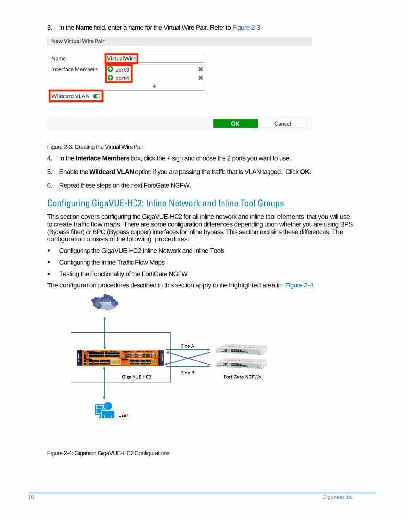
3. In the Name field, enter a name for the Virtual Wire Pair. Refer to Figure 2-3.
Figure 2-3: Creating the Virtual Wire Pair
4. In the Interface Members box, click the + sign and choose the 2 ports you want to use.
5. Enable the Wildcard VLAN option if you are passing the traffic that is VLAN tagged. Click OK.
6. Repeat these steps on the next FortiGate NGFW.
Configuring GigaVUE-HC2: Inline Network and Inline Tool Groups This section covers configuring the GigaVUE-HC2 for all inline network and inline tool elements that you will use to create traffic flow maps. There are some configuration differences depending upon whether you are using BPS (Bypass fiber) or BPC (Bypass copper) interfaces for inline bypass. This section explains these differences. The configuration consists of the following procedures:
Configuring the GigaVUE-HC2 Inline Network and Inline Tools
Configuring the Inline Traffic Flow Maps
Testing the Functionality of the FortiGate NGFW
The configuration procedures described in this section apply to the highlighted area in Figure 2-4.
Figure 2-4: Gigamon GigaVUE-HC2 Configurations

FortiGate NGFW with Gigamon Deployment Guide 11 + FortiGate NGFW with Gigamon Deployment Guide 11
+
Configuring the GigaVUE-HC2 Inline Network and Inline Tools This section describes the steps needed to configure inline network bypass pairs and an inline network group for those pairs. As the enterprise infrastructure grows, you can add additional inline network pairs to the inline network group. The basic steps are as follows:
Step 1: Configure the Inline Network Bypass Pair
Step 2: Configure the Inline Network Group (if applicable)
Step 3: Configure the Inline Tools
NOTE: This section assumes all the ports to which the network devices are connected are set as Inline Network port types. For specific instructions on completing these tasks, refer to the User Guides and Technical Documentation in the Customer Portal. Step 1: Configuring the Inline Network Bypass Pair To configure the inline network bypass pair, do the following:
1. Log into GigaVUE-FM and select Physical Nodes.
2. Select the GigaVUE-HC2 from the list of physical nodes that GigaVUE-FM is managing.
3. Select Inline Bypass > Inline Networks.
NOTE: If there is a bypass combo module in the GigaVUE-HC2, there will be four preconfigured Inline Network port pairs as shown in Figure 2-5. If your network is 1G or 10G fiber, use one of these preconfigured inline bypass pairs and move on to Step 2. If your network is 1G copper, perform the following steps.
Figure 2-5: Inline Networks Page

12 Gigamon Inc.
4. Click New. The Inline Network configuration page displays. Refer to Figure2-6.
Figure 2-6: Inline Network Pair Configuration
5. On the Inline Network page, do the following (refer to Figure 2-6):
a. In the Alias field, type an alias that will help you remember which network link this Inline Network bypass pair represents. For example, InLineNet1.
b. From the Port A drop-down list, select the port A as it is represented in the network topology diagram shown in Figure 1-1. The value in the Port B drop-down list is automatically populated once you select Port A.
Important: It is essential for Side A and Side B of the GigaVUE-HC2 to match with Side A and Side B of the FortiGate NGFW. If they don’t match, the traffic distribution or the Inline Tool Group will not work correctly.
c. Retain the default selection in Traffic Path and Link Failure Propagation.
d. Select Physical Bypass. This minimizes packet loss during traffic map changes.
6. Click Save.
NOTE: Traffic Path is set to Bypass to prevent packet loss until the inline tool groups and maps have been set up. After the inline tool groups and maps are configured, the traffic path can be set to inline tool as described in the subsequent section.
7. Repeat these steps for all other network links (if applicable).
Step 2: Configuring the Inline Network Group To configure the inline network group (if applicable), do the following:
1. In GigaVUE-FM, select Inline Bypass > Inline Network Groups.
2. Click New.
3. In the Alias field, type an alias that represents the inline network group. For example, FortiGate-A_NGroup.
FortiGate NGFW with Gigamon Deployment Guide 13 + FortiGate NGFW with Gigamon Deployment Guide 13
+
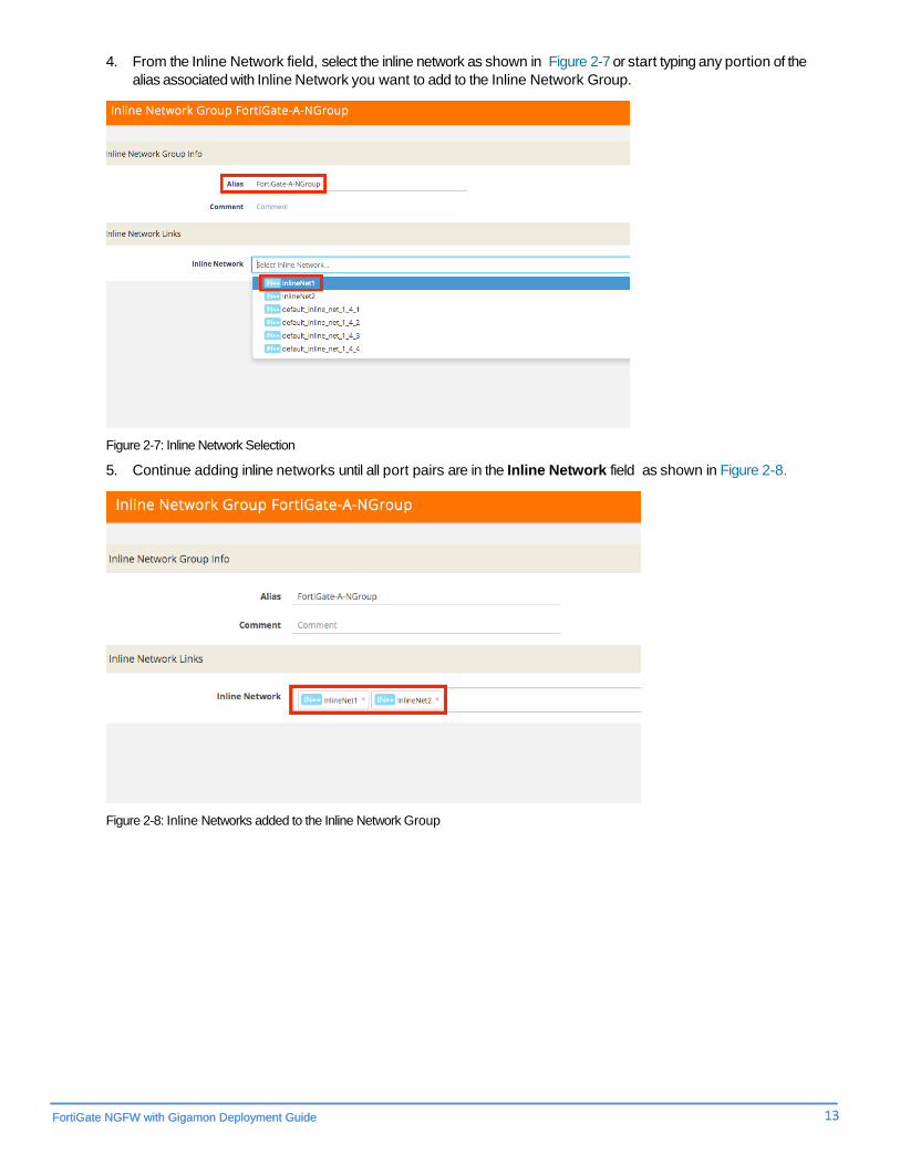
4. From the Inline Network field, select the inline network as shown in Figure 2-7 or start typing any portion of the alias associated with Inline Network you want to add to the Inline Network Group.
Figure 2-7: Inline Network Selection
5. Continue adding inline networks until all port pairs are in the Inline Network field as shown in Figure 2-8.
Figure 2-8: Inline Networks added to the Inline Network Group

14 Gigamon Inc.
6. Click Save.
The Inline Network Groups page is displayed as shown in Figure 2-9.
Figure 2-9: Finished list of Inline Network Groups
Step 3: Configuring the Inline Tools This section describes the steps necessary to define the inline tool port pairs and the inline tool group that will be used in the traffic flow map defined in Configuring the Traffic Flow Map with a Pass All Rule.
1. In GigaVUE-FM, select Inline Bypass > Inline Tools.
Figure 2-10: Navigating to the Inline Tools page
2. Click New to open the configuration page for inline tools.
3. In the Alias field, type an alias that will help you remember which inline tool this inline tool pair represents. For example, FortiGate.
4. In the Ports section, specify the ports as follows:
• For Port A, specify the port that corresponds to Side A in the network diagram
• For Port B, specify the port that corresponds to Side B in the network diagram
For the network diagram, refer to Figure 1-1.
Important: It is essential for Port A and Port B to match Side A and Side B of the inline network port pairs respectively.

FortiGate NGFW with Gigamon Deployment Guide 15 + FortiGate NGFW with Gigamon Deployment Guide 15
+
5. Leave the default setting for the remaining configuration options. Your configuration should be similar to the example shown in Figure 2-11.
Figure 2-11: Inline Tool Pair Configuration
6. Click Save.
7. Repeat steps 2 through 6 for all additional FortiGate NGFWs.
NOTE: The failure action for this inline tool is ToolBypass. This means that the GigaVUE-HC2 will not send traffic to this inline tool if it is considered to be in a failure mode. The online help fully describes other options for inline tool. The other options have very different effects on the overall traffic flow. If you have not enabled the heartbeat feature, the failover action will only take place if one of the inline tool port links go down.
16 Gigamon Inc.
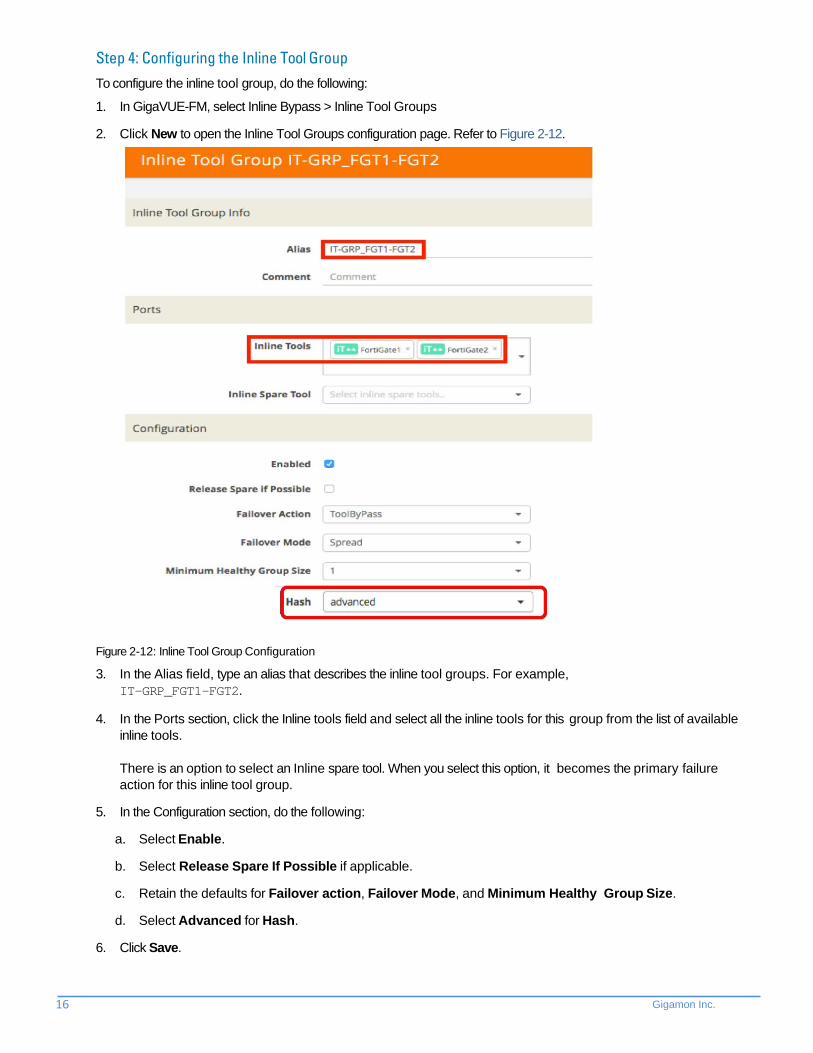
Step 4: Configuring the Inline Tool Group To configure the inline tool group, do the following:
1. In GigaVUE-FM, select Inline Bypass > Inline Tool Groups
2. Click New to open the Inline Tool Groups configuration page. Refer to Figure 2-12.
Figure 2-12: Inline Tool Group Configuration
3. In the Alias field, type an alias that describes the inline tool groups. For example, IT-GRP_FGT1-FGT2.
4. In the Ports section, click the Inline tools field and select all the inline tools for this group from the list of available inline tools. There is an option to select an Inline spare tool. When you select this option, it becomes the primary failure action for this inline tool group.
5. In the Configuration section, do the following:
a. Select Enable.
b. Select Release Spare If Possible if applicable.
c. Retain the defaults for Failover action, Failover Mode, and Minimum Healthy Group Size.
d. Select Advanced for Hash.
6. Click Save.

FortiGate NGFW with Gigamon Deployment Guide 17 + FortiGate NGFW with Gigamon Deployment Guide 17
+
Configuring the Inline Traffic Flow Maps This section describes the high-level process for configuring traffic to flow from the inline network links to the inline FortiGate tool group, allowing you to test the deployment functionality of the Fortinet appliances within the group. Perform the following steps:
Step 1: Configure the Traffic Flow Map with a Pass All Rule
Step 2: Change Inline Network Traffic Path to Inline Tool
After completing these steps, you will be ready to test the deployment of the FortiGate appliances. Refer to Testing the Functionality of the FortiGate NGFWs describes the test procedure.
Configuring the Traffic Flow Map with a Pass All Rule This section describes the configuration of a traffic flow map between the Inline Network Group and the Inline Tool Group:
1. In GigaVUE-FM, navigate to the Maps page.
2. Click New. The New Map page displays.
Figure 2-13: Configuration for Pass All Map
3. In the Alias field, enter a map alias that represents the network source and tool destination.
4. From the Type drop-down list, select Inline.
5. From the Subtype drop-down list, select Pass All.
6. From the Traffic Path drop-down list, select Normal.
7. Under Map Source and Destination, select the Source and Destination fields as follows:
a. Set Source to the inline network group that you created in Step 2: Configure the Inline Network Group. Choose your inline network if you do not have an Inline Network Group.
18 Gigamon Inc.
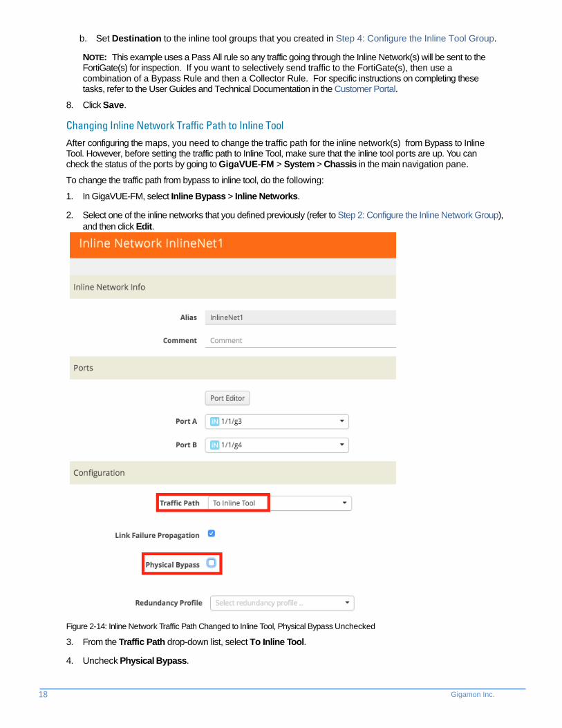
b. Set Destination to the inline tool groups that you created in Step 4: Configure the Inline Tool Group.
NOTE: This example uses a Pass All rule so any traffic going through the Inline Network(s) will be sent to the FortiGate(s) for inspection. If you want to selectively send traffic to the FortiGate(s), then use a combination of a Bypass Rule and then a Collector Rule. For specific instructions on completing these tasks, refer to the User Guides and Technical Documentation in the Customer Portal.
8. Click Save.
Changing Inline Network Traffic Path to Inline Tool After configuring the maps, you need to change the traffic path for the inline network(s) from Bypass to Inline Tool. However, before setting the traffic path to Inline Tool, make sure that the inline tool ports are up. You can check the status of the ports by going to GigaVUE-FM > System > Chassis in the main navigation pane.
To change the traffic path from bypass to inline tool, do the following:
1. In GigaVUE-FM, select Inline Bypass > Inline Networks.
2. Select one of the inline networks that you defined previously (refer to Step 2: Configure the Inline Network Group), and then click Edit.
Figure 2-14: Inline Network Traffic Path Changed to Inline Tool, Physical Bypass Unchecked
3. From the Traffic Path drop-down list, select To Inline Tool.
4. Uncheck Physical Bypass.

FortiGate NGFW with Gigamon Deployment Guide 19 + FortiGate NGFW with Gigamon Deployment Guide 19
+
5. Click Save.
6. Repeat step 3 and step 4 for each inline network in the inline network group (if applicable).
Testing the Functionality of the FortiGate NGFWs One of the easiest ways to determine if the FortiGate NGFW is working properly is by attempting to access a website that should be blocked. In the example below, policy has been created to block access to the website foo.com.
1. From Policy & Objects, select IPv4 Virtual Wire Pair Policy.
2. Click New and create a policy as shown in Figure 2-15.
Figure 2-15: Creating a New Policy
20 Gigamon Inc.
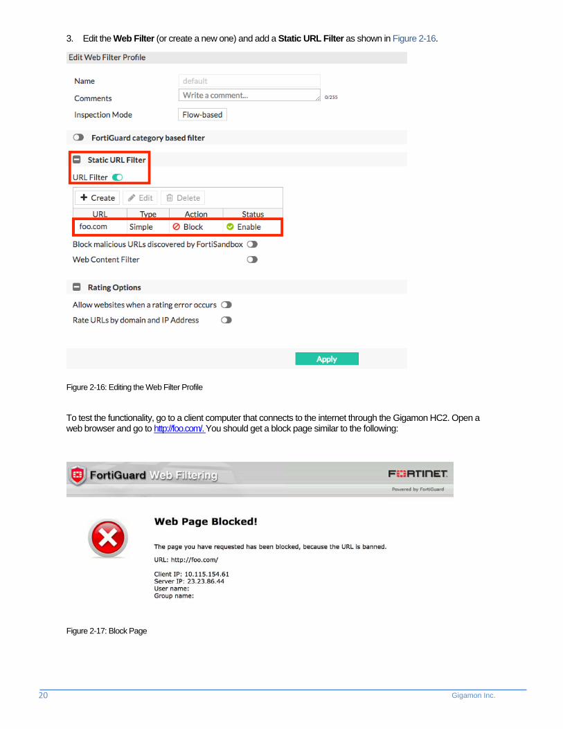
3. Edit the Web Filter (or create a new one) and add a Static URL Filter as shown in Figure 2-16.
Figure 2-16: Editing the Web Filter Profile
To test the functionality, go to a client computer that connects to the internet through the Gigamon HC2. Open a web browser and go to http://foo.com/. You should get a block page similar to the following:
Figure 2-17: Block Page

FortiGate NGFW with Gigamon Deployment Guide 21 + FortiGate NGFW with Gigamon Deployment Guide 21
+
Summary and Conclusions
The previous chapters described how to deploy Gigamon GigaVUE-HC2 bypass protection with FortiGate NGFW appliances. This combined solution using the Gigamon-GigaVUE-HC2 chassis for inline tool high availability and traffic distribution achieves the following objectives:
High availability of FortiGate NGFW because each inline security solution can be put into a Gigamon inline tool group with tool failover actions. The inline tool group can be optimized for each security need, regardless of whether the tool goes off-line due to an outage or planned maintenance.
Traffic distribution to multiple FortiGate NGFW appliances for load sharing across multiple instances.
Seamless scalability for an increasing network infrastructure as well as the inline security tools to accommodate the additional traffic.
Ultimate flexibility of adding new types of inline security tools without physical change control because all new tools are physically added to the GigaVUE-HC2 and logically added to the path through traffic flow maps.
For more information on the GigaVUE-HC2 bypass protection, high availability, and scalability provided by Gigamon’s Security Delivery Platform, go to www.gigamon.com.
Available Documentation
Document Summary
GigaVUE-FM and GigaVUE-VM User’s Guide
Provides an overview of the GigaVUE Fabric Manager including, initial configuration, upgrade instructions, setting up accounts and configuring the GigaVUE nodes.
GigaVUE-OS CLI User’s Guide Describes how to configure and operate the GigaVUE-OS software from the command line interface.
GigaVUE-OS H-VUE™ User’s Guide Describes how to use the Web-based H-VUE interface to configure and operate the GigaVUE H Series software.
Documentation Feedback To send feedback and report issues in our documentation, complete the short survey at the following link: https://www.surveymonkey.com/r/gigamondocumentationfeedback
Contacting Gigamon Support For issues with Gigamon products, refer to http://www.gigamon.com/support-and-services/contact-support for Technical Support hours and contact information. You can also email Technical Support at [email protected]. Refer also to the customer portal at https://gigamoncp.force.com/gigamoncp/.
Contacting Fortinet Support For issues related to Fortinet products, refer to your Support Agreement with Fortinet and follow the directions on how to open a Support Case.

22 Gigamon Inc.

![[Solution Brief] Enhancing NGFW Security with …€¦ · ENHANCING NGFW SECURITY WITH AUTOMATED MALWARE ANALYSIS ... [Solution Brief] Enhancing NGFW Security with Automated ... sonicwall,](https://img.pdfslide.net/doc/110x75/5b1e9fd47f8b9a7f2f8bb1cc/solution-brief-enhancing-ngfw-security-with-enhancing-ngfw-security-with-automated.jpg)