Embed Size (px)
Citation preview
Chapter 1
Joint Source-Channel
Coding for Video
Communications
Fan Zhai1, Yiftach Eisenberg2, and Aggelos K. Katsaggelos2
1 Department of Digital Video, DAV, HPATexas Instruments, Dallas, TX 75243, USA
2 Department Electrical and Computer EngineeringNorthwestern University, Evanston, IL 60208, USA
1.1 Introduction
The compression or coding of a signal (e.g., speech, text, image, video) has beena topic of great interest for a number of years. Numerous results and success-ful compression standards exist. Source compression is the enabling technologybehind the multimedia revolution we are experiencing. The two primary appli-cations for data compressing are storage and transmission. Video transmissionis the topic of this chapter. Video transmission applications, such as on-demandvideo streaming, videotelephony, and videoconferencing, have gained increasedpopularity.
In a video communication system, the video is first compressed and thensegmented into fixed or variable length packets and multiplexed with other typesof data, such as audio. Unless a dedicated link that can provide a guaranteedquality of service (QoS) is available between the source and the destination, databits or packets may be lost or corrupted, due to either traffic congestion or biterrors due to impairments of the physical channels. Such is the case, for example,with the current Internet and wireless networks. Due to its best effort design,the current Internet makes it difficult to provide the QoS, such as bandwidth,packet loss probability, and delay needed by video communication applications.
1
2CHAPTER 1. JOINT SOURCE-CHANNEL CODING FOR VIDEO COMMUNICATIONS
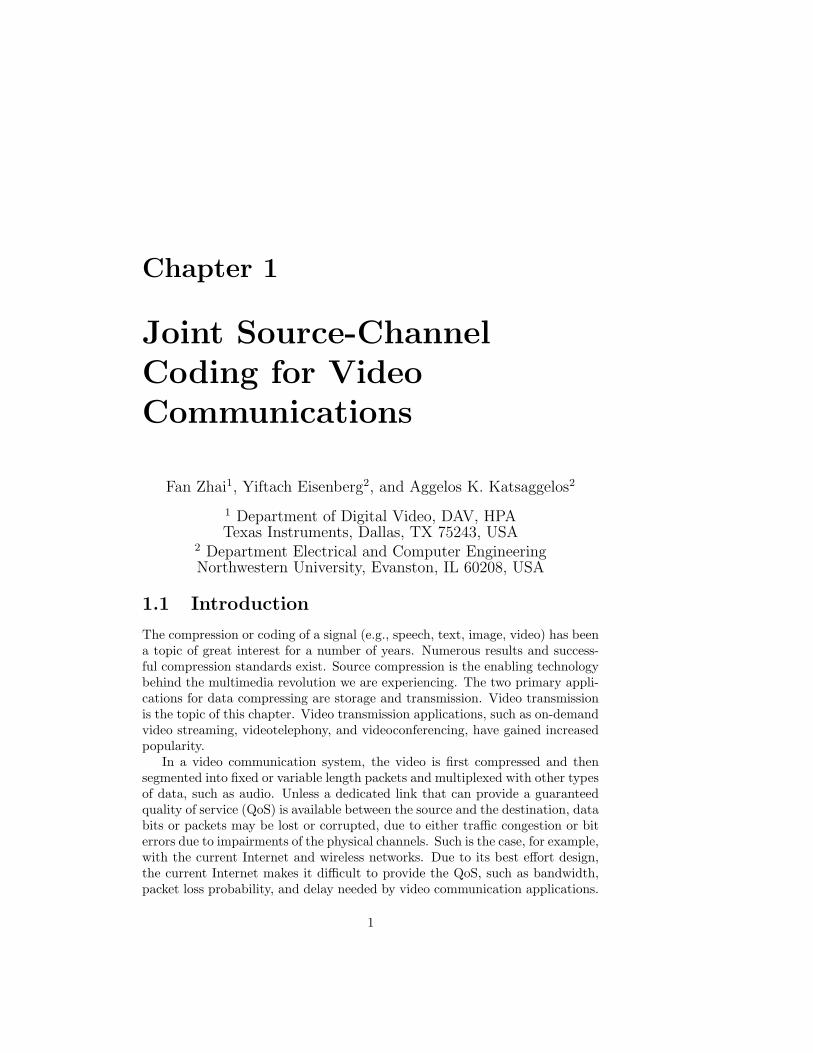
Compared to wired links, wireless channels are much noisier because of fading,multi-path, and shadowing effects, which results in a much higher bit error rate(BER) and consequently an even lower throughput. Figure 1.1 illustrates theeffect of channel errors to a typical compressed video sequence in the presenceof packet loss.
(a) (b)
(c) (d)
Figure 1.1: Illustration of the effect of channel errors to a video stream com-pressed using the H.263 standard: (a) Original Frame; Reconstructed frameat (b) 3% packet loss (c) 5% packet loss (d) 10% packet loss (QCIF Foremansequence, frame 90, coded at 96 kbps and frame rate 15 fps).
Due to the “unfriendliness” of the channel to the incoming video packets,they have to be protected so that the best possible quality of the received videois achieved at the receiver. A number of techniques, which are collectively callederror resilient techniques have been devised to combat transmission errors. Theycan be grouped into [1]: (i) those introduced at the source and channel coder tomake the bitstream more resilient to potential errors; (ii) those invoked at thedecoder upon detection of errors to conceal the effects of errors, and (iii) thosewhich require interactions between the source encoder and decoder so that theencoder can adapt its operations based on the loss conditions detected at thedecoder.
1.1. INTRODUCTION 3
A number of reasons make the error resiliency problem a challenging one.First, compressed video streams are sensitive to transmission errors because ofthe use of predictive coding and variable-length coding (VLC) by the sourceencoder. Due to the use of spatio-temporal prediction, a single bit error canpropagate in space and time. Similarly, because of the use of VLCs, a single biterror can cause the decoder to loose synchronization, so that even successfullyreceived subsequent bits become unusable. Second, both the video source andthe channel conditions are time-varying, and therefore it is not possible to derivean optimal solution for a specific transmission of a given video signal. Finally,severe computational constraints are imposed for real-time video communicationapplications.
The development of error resilient approaches or approaches for increasingthe robustness of the multimedia data to transmission errors is a topic of theutmost importance and interest. To make the compressed bitstream resilient totransmission errors, redundancy must be added into the stream. Such redun-dancy can be added either by the source or the channel coder. Shannon said itfifty years ago [2], that source coding and channel coding can be separated foroptimal performance communication systems. The source coder should com-press a source to a rate below the channel capacity while achieving the smallestpossible distortion, and the channel coder can add redundancy through ForwardError Correction (FEC) to the compressed bitstream to enable the correctionof transmission errors. Following Shannon’s separation theory resulted in majoradvances on source coding (e.g., rate-distortion optimal coders and advanced en-tropy coding algorithms) and channel coding (e.g., Reed-Solomon codes, Turbocodes, and Tornado codes). The separation theory not only promises that theseparate design of source and channel coding does not introduce any perfor-mance sacrifice, but it also greatly reduces the complexities of a practical systemdesign. However, the assumptions on which separation theory is based (infinitelength codes, delay, and complexity) may not hold in a practical system. Thisleads to the development of the approach of joint consideration of source codingand channel coding, referred to as joint source-channel coding (JSCC). JSCCcan greatly improve the system performance when there are, for example, strin-gent end-to-end delay constraints or implementation complexity concerns.
Our purpose in this chapter is to review the basic elements of some of themore recent approaches towards JSCC for wired and wireless systems alike. Therest of the chapter is organized as follows. We first provide basic rate-distortiondefinitions in addressing the need for JSCC in Sect. 1.2. We then describe thebasic components in a video compression and transmission systems in Sect. 1.3,followed by a discussion on channel coding techniques that are widely used forvideo communications in Sect. 1.4. In Sect. 1.5 the JSCC problem formulationis presented, followed by examples of several practical implementations. Finally,Sect. 1.6 contains concluding remarks.
4CHAPTER 1. JOINT SOURCE-CHANNEL CODING FOR VIDEO COMMUNICATIONS
1.2 On Joint Source-Channel Coding
Due to the high bandwidth of the raw video data, compression is necessaryfor reducing the source redundancy. With ideal lossless compression, sourceredundancy can be entirely removed without any quality loss. Since the mini-mum bit rate achieved using lossless compression is usually much higher thanthe available channel capacity, lossy compression is generally required for videotransmission applications. The same way entropy determines the lowest pos-sible rate for lossless compression, rate-distortion (R-D) theory [2, 3] addressesthe same question for lossy compression.
1.2.1 Rate-distortion theory
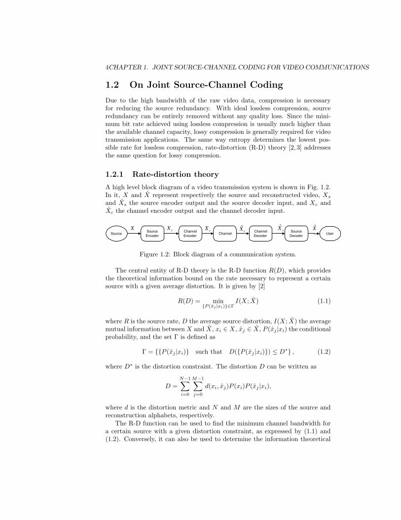
A high level block diagram of a video transmission system is shown in Fig. 1.2.In it, X and X represent respectively the source and reconstructed video, Xs
and Xs the source encoder output and the source decoder input, and Xc andXc the channel encoder output and the channel decoder input.
Source Source
Encoder Source
Decoder Channel Decoder
Channel Channel Encoder
User X
c X ˆ s X X ˆ s X ˆ c X
Figure 1.2: Block diagram of a communication system.
The central entity of R-D theory is the R-D function R(D), which providesthe theoretical information bound on the rate necessary to represent a certainsource with a given average distortion. It is given by [2]
R(D) = min{P (xj |xi)}∈Γ
I(X; X) (1.1)
where R is the source rate, D the average source distortion, I(X; X) the averagemutual information between X and X, xi ∈ X, xj ∈ X, P (xj |xi) the conditionalprobability, and the set Γ is defined as
Γ = {{P (xj |xi)} such that D({P (xj |xi)}) ≤ D∗} , (1.2)
where D∗ is the distortion constraint. The distortion D can be written as
D =N−1∑
i=0
M−1∑
j=0
d(xi, xj)P (xi)P (xj |xi),
where d is the distortion metric and N and M are the sizes of the source andreconstruction alphabets, respectively.
The R-D function can be used to find the minimum channel bandwidth fora certain source with a given distortion constraint, as expressed by (1.1) and(1.2). Conversely, it can also be used to determine the information theoretical
1.2. ON JOINT SOURCE-CHANNEL CODING 5
bounds on the average distortion subject to a channel capacity constraint, viathe distortion-rate function, D(R), which is the dual of (1.1), defined as,
D(R) = min{P (xj |xi)}∈Φ
D(X; X) (1.3)
where Φ is defined as
Φ = {{P (xj |xi)} such that R({P (xj |xi)}) ≤ R∗} ,
with R∗ the rate constraint.Note that the D(R) function may be more widely applicable in practical
image/video communication systems, since, as a practical matter, the aim isusually to deliver the best quality image/video subject to certain channel band-width, rather than the opposite. R-D theory is of fundamental importance inthat it conceptually provides the information bounds for lossy data compression.However, it is usually difficult to find closed-form expressions for the R(D) orD(R) functions. In this case, one resorts to numerical algorithm for specifyingthe operational R-D function [4].
1.2.2 Practical constraints in video communications
We can see from (1.1) that the process of finding the optimal compression schemerequires searching over the entire set of conditional probabilities that satisfy thedistortion constraint shown in (1.2). Under the assumption that the sourceencoder output is identical to the source decoder input, i.e., Xs = Xs, the prob-lem becomes a pure source coding problem, since the conditional probabilitiesP (xj |xi) have nothing to do with the channel. However, such an assumptiongenerally requires an ideal channel coding scheme, such that error free trans-mission of the source output over a noisy channel with source bit rate R(D) lessthan the channel capacity can be guaranteed.
However, such ideal channel coding generally requires infinite length codewords, which can only be realized without complexity and delay constraints,both of which are important factors in practical real-time systems. Due tothese constraints, channel coding cannot achieve channel capacity. Hence, mostpractical channel coding schemes do not provide an idealized error free commu-nication path between source and destination, and thus the overall distortionconsists of both source distortion and channel distortion. For this reason, min-imizing the total distortion usually requires jointly designing the source andchannel encoders, which is referred to as joint source-channel coding.
At the receiver side, gains may be obtained by jointly designing the channeland source decoders, which is referred to as joint source-channel decoding. Inusing joint source-channel decoding, the channel decoder does not make harddecisions on the output Xs. Instead, the decoder makes soft decisions in order toallow the source decoder to make use of information such as the signal-to-noiseratio (SNR) of the corrupted code. Alternatively, such soft decisions can beregarded as hard decisions plus a confidence measure. Soft-decision processing
6CHAPTER 1. JOINT SOURCE-CHANNEL CODING FOR VIDEO COMMUNICATIONS
used in joint source channel decoding can usually help improve the coding gainby about 2 dB compared to hard-decision processing [5]. In this chapter, wefocus on what is performed at the sender side.
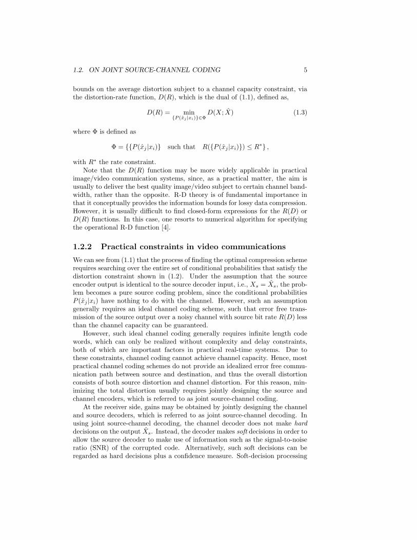
1.2.3 Illustration
The basic idea of JSCC is illustrated in Fig. 1.3. When the channel is error free,increased bit rate leads to decreased distortion, as in standard rate-distortion(R-D) theory. This is illustrated by the lowest curve in Fig. 1.3, in which thelowest distortion is obtained by utilizing the largest available source bit rate,represented by the point (R1, D1). However, when channel errors are present,this trend may not hold, since the overall distortion consists of both sourceand channel distortions. For a given channel rate, as more bits are allocated tosource coding, fewer will be left for channel coding, which leads to less protectionand higher channel distortion. As shown in Fig. 1.3, an optimal point exists forgiven channel distortions in allocating bits between source and channel coding.Note that different channel error rates result in different optimal allocations.This is indicated by the points (R2, D2) and (R3, D3) on the two curves withdifferent channel error rates.
Source rate D1
D2
R2 R1 R3
D3
Overall distortion
Error rate
Figure 1.3: Illustration of joint source-channel coding.
The tradeoff between source and channel coding has been studied from atheoretical standpoint based on the use of vector quantizers [6, 7]. In general,JSCC is accomplished by designing the quantizer and entropy coder jointly forgiven channel characteristics, as in [6, 8]. There is a substantial number ofresearch results in this area. Interested readers can refer to [9] for a comprehen-sive review on this topic. In this chapter, we focus on the specific applicationof JSCC in image and video communications, where JSCC usually faces threetasks: finding an optimal bit allocation between source coding and channel cod-ing for given channel loss characteristics; designing the source coding to achieve
1.3. VIDEO COMPRESSION AND TRANSMISSION 7
the target source rate; and designing the channel coding to achieve the requiredrobustness [10, 11]. These tasks, although stated separately, are inter-related,forming the backbone of the integrated nature of JSCC.
We have discussed the basic concept underlying JSCC and its significancein image/video communications. Next, we will first provide an overview of thevideo compression and transmission systems. Then we will highlight the keycomponents of JSCC for video applications, such as the different forms of errorresilient source coding, channel codes used to deal with different types of channelerrors, the general problem formulation and the general solution approach. Inaddition to the commonly used video compression standards, such as MPEGxand H.26x, we also briefly discuss wavelet and subband-based video compressionschemes, since they are also widely used.
1.3 Video Compression and Transmission
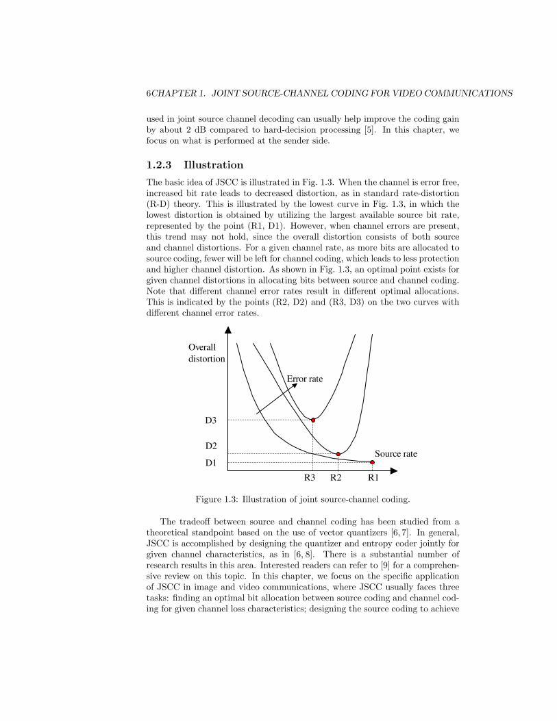
1.3.1 Video transmission system
We begin by providing a brief high-level overview of a packet-based video trans-mission system. Some of the major conceptual components found in such asystem are shown in Fig. 1.4.
�
Transport�layer�
video�input�
Receiver�side�Sender�side�
�networks�
Application�layer�
Video�encoder�
Transport��layer�
Application�layer�
Video�decoder�
Rate�control�
�
Figure 1.4: Video transmission system architecture.
Most practical communication networks have limited bandwidth and arelossy by nature. Facing these challenges, the video encoder has two main objec-tives: to compress the original video sequence and to make the encoded sequenceresilient to errors. Compression reduces the number of bits used to representthe video sequence by exploiting both temporal and spatial redundancy. On theother hand, to minimize the effects of losses on the decoded video quality, thesequence must be encoded in an error resilient way. A recent review of resilientvideo coding techniques can be found in [1]. The source bit rate is shaped orconstrained by a rate controller that is responsible for allocating bits to each
8CHAPTER 1. JOINT SOURCE-CHANNEL CODING FOR VIDEO COMMUNICATIONS
video frame or packet. This bit rate constraint is set based on the estimatedchannel state information (CSI) reported by the lower layers, such as the appli-cation and transport layers. It is mentioned here that the system in Fig. 1.4 is asimplified version of a seven or a five layer Open Systems Interconnection (OSI)reference model. For example, in both OSI models the network, data link, andphysical layers are below the transport layer. In the subsequent sections we willbe referring to the various layers, since allowing the various layers to exchangeinformation leads to cross-layer design of a video communication system, whichis a central theme in this chapter.
In Fig. 1.4, the network block represents the communication path betweenthe sender and the receiver. This path may include routers, subnets, wirelesslinks, etc. The network may have multiple channels (e.g., a wireless network)or paths (e.g., a network with path diversity), or support QoS (e.g., integratedservices or differentiated services networks). Packets may be dropped in thenetwork due to congestion, or at the receiver due to excessive delay or unrecov-erable bit errors in a wireless network. To combat packet losses, parity checkpackets used for FEC may be generated at the application/transport layer. Inaddition, lost packets may be retransmitted if the application allows.
For many source-channel coding applications, the exact details of the net-work infrastructure may not be available to the sender and they may not alwaysbe necessary. Instead, what is important in JSCC is that the sender has ac-cess to or can estimate certain network characteristics, such as the probabilityof packet loss, the transmission rate and the round-trip-time (RTT). In mostcommunication systems, some form of CSI is available at the sender, such as anestimate of the fading level in a wireless channel or the congestion over a routein the Internet. Such information may be fed back from the receiver and can beused to aid in the efficient allocation of resources.
On the receiver side, the transport and application layers are responsiblefor de-packetizing the received transport packets, channel decoding (if FECis used), and forwarding the intact and recovered video packets to the videodecoder. The video decoder then decompresses the video packets and displaysthe resulting video frames in real-time (i.e., the video is displayed continuouslywithout interruption at the decoder). The video decoder typically employs errordetection and concealment techniques to mitigate the effects of packet loss.The commonality among all error concealment strategies is that they exploitcorrelations in the received video sequence to conceal lost information.
1.3.2 Video compression basics
In this section, we focus on one of the most widely used video coding techniques,that of Hybrid Block-based Motion-Compensated (HBMC) video coding, asutilized in the H.26x and MPEGx standards. In this type of video codecs, eachvideo frame is presented in block-shaped units of associated luma and chromasamples (16 × 16 region) called MBs (macroblocks).
As shown in Fig. 1.5(a), the core of the encoder is motion compensatedprediction (MCP). The first step in MCP is motion estimation (ME), aiming
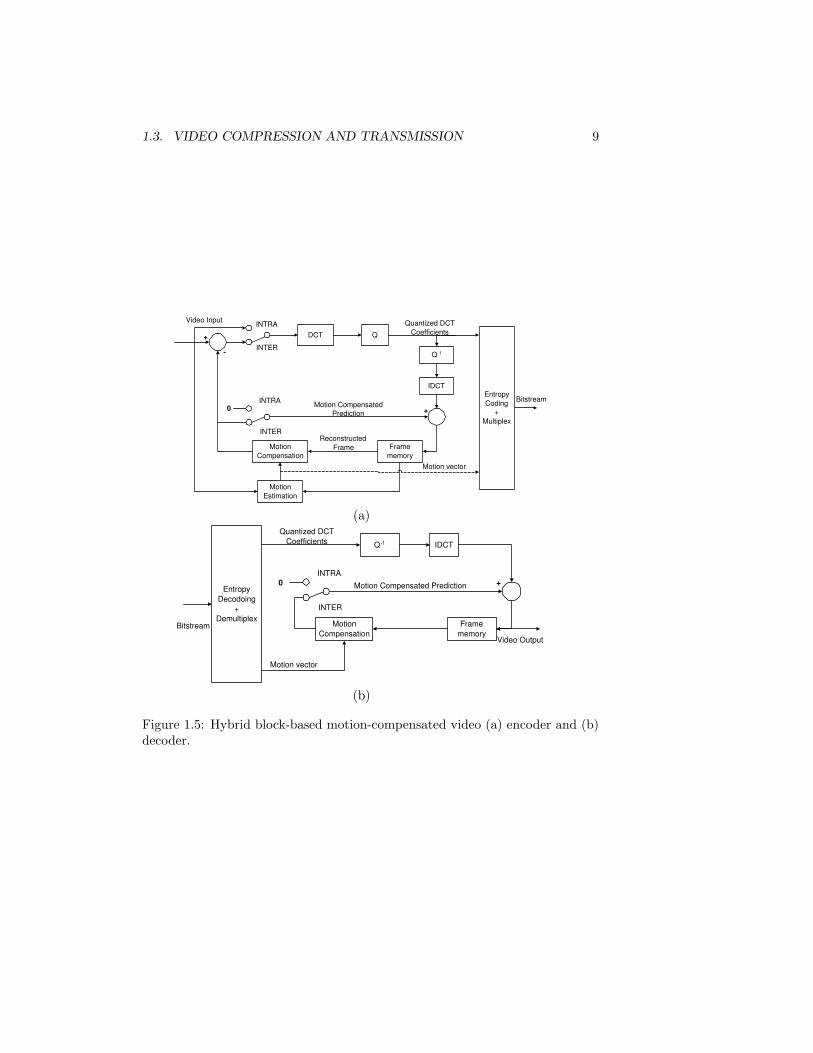
1.3. VIDEO COMPRESSION AND TRANSMISSION 9
DCT Q
Motion Compensation
Frame memory
Motion Estimation
Entropy Coding
+ Multiplex
IDCT
Bitstream
Q -1
+
- INTER
INTRA
0 INTRA
INTER
Video Input
Motion vector
+
Motion Compensated Prediction
Quantized DCT Coefficients
Reconstructed Frame
(a)
Q -1 IDCT
Motion Compensation
Frame memory
Entropy Decodoing
+ Demultiplex
Bitstream
0 INTRA
INTER
Video Output
Motion vector
+ Motion Compensated Prediction
Quantized DCT Coefficients
(b)
Figure 1.5: Hybrid block-based motion-compensated video (a) encoder and (b)decoder.
10CHAPTER 1. JOINT SOURCE-CHANNEL CODING FOR VIDEO COMMUNICATIONS
to find the region from the previous frame that best matches each MB in thecurrent frame. The offset between the MB and the prediction region is knownas a motion vector. The motion vectors form a motion field, which is differen-tially entropy encoded. The second step is motion compensation (MC), wherethe reference frame is produced by applying the motion field to the previouslyreconstructed frame. The prediction error, known as the displaced frame dif-ference (DFD), is obtained by subtracting the reference frame from the currentframe.
Following MCP, the DFD is processed by three major blocks, namely, trans-form, quantization, and entropy coding. The key reason in using a transformcoding is to de-correlate the data so that the associated energy in the trans-form domain is more compactly represented and thus the resulting transformcoefficients are easier to encode. The Discrete Cosine Transform (DCT) is oneof the most widely used transforms in image and video coding due to its hightransform coding gain and low computational complexity. Quantization intro-duces loss of information, and is the primary source of the compression gain.Quantized coefficients are entropy encoded, e.g., using Huffman or arithmeticcoding. The DFD is first divided into 8×8 blocks, and the DCT is then appliedto each block, with the resulting coefficients quantized. In most Block-basedMotion-Compensated (BMC) standards, a given MB can be intra-frame coded,inter-frame coded using motion compensated prediction, or simply replicatedfrom the previously decoded frame. These prediction modes are denoted asINTRA, INTER, and SKIP modes, respectively. Quantization and coding areperformed differently for each MB according to its mode. Thus, the codingparameters for each MB are typically represented by its prediction mode andquantization parameter.
At the decoder, as shown in Fig. 1.5(b), the inverse DCT (IDCT) is ap-plied to the quantized DCT coefficients to obtain a reconstructed version of theDFD; the reconstructed version of the current frame is obtained by adding thereconstructed DFD to the previously reconstructed frame.
Besides DCT-based video compression, the wavelet representation providesa multi-resolution/multi-scale expression of a signal with localization in bothtime and frequency. One of the advantages of wavelet coders in both still imageand video compression is that they are free of blocking artifacts. In addition,they usually offer continuous data rate scalability.
During the last decade, the discrete wavelet transform (DWT) and subbanddecomposition have gained increased popularity in image coding due to thesubstantial contributions in [12], [13], JPEG2000 [14], and others. Recently,there has also been active research applying the DWT to video coding [15–18].Among the above studies, 3D wavelet or subband video codecs have receivedspecial attention due to their inherent feature of full scalability [17, 18]. Untilrecently, the disadvantage of these approaches has been their poor coding ef-ficiency caused by inefficient temporal filtering. A major breakthrough whichhas greatly improved the coding efficiency and led to renewed efforts towardthe standardization of wavelet-based scalable video coders has come from thecontributions of combining lifting techniques with 3D wavelet or subband cod-
1.3. VIDEO COMPRESSION AND TRANSMISSION 11
ing [19,20].
1.3.3 Channel Models
The development of mathematical models which accurately capture the prop-erties of a transmission channel is a very challenging but extremely importantproblem. For video applications, two fundamental properties of the communi-cation channel are the probability of packet loss and the delay needed for eachpacket to reach the destination. In wired networks, channel errors usually ap-pear in the form of packet loss and packet truncation. In wireless networks,besides packet loss and packet truncation, bit error is another common sourceof error. Packet loss and truncation are usually due to network traffic and clockdrift, while bit corruption is due to the noisy air channel [21].
Internet
In the Internet, queuing delays experienced in the network can be a significantdelay component. The Internet, therefore, can be modeled as an independenttime-invariant packet erasure channel with random delays, as in [22]. In real-time video applications, a packet is typically considered lost and discarded ifit does not arrive at the decoder before its intended playback time. Thus thepacket loss probability is made up of two components: the packet loss probabilityin the network and the probability that the packet experiences excessive delay.Combining these two factors, the overall probability of loss for packet k is givenby
ρk = εk + (1 − εk)P{∆Tn(k) > τ},
where εk is the probability of packet loss in the network, ∆Tn(k) is the networkdelay for packet k, and τ is the maximum allowable network delay for thispacket.
Wireless Channel
Compared to their wire-line counterparts, wireless channels exhibit higher biterror rates, typically have a smaller bandwidth, and experience multi-path fad-ing and shadowing effects. At the IP level, the wireless channel can also betreated as a packet erasure channel, as it is “seen” by the application. In thissetting, the probability of packet loss can be modeled by a function of trans-mission power used in sending each packet and the CSI. Specifically, for a fixedtransmission rate, increasing the transmission power will increase the receivedSNR and result in a smaller probability of packet loss. This relationship couldbe determined empirically or modeled analytically. For example, in [23], ananalytical model based on the notion of outage capacity is used. In this model,a packet is lost whenever the fading realization results in the channel having acapacity less than the transmission rate. Assuming a Rayleigh fading channel,
12CHAPTER 1. JOINT SOURCE-CHANNEL CODING FOR VIDEO COMMUNICATIONS
the resulting probability of packet loss is given by
ρk = 1 − exp
(
1
PkS(θk)(2R/W − 1)
)
,
where R is the transmission rate (in source bits per sec), W the bandwidth, Pk
the transmission power allocated to the k-th packet, and S(θk) the normalizedexpected SNR given the fading level, θk. Another way to characterize channelstate is to use bounds for the bit error rate with regard to a given modulation andcoding scheme; for example, in [24, 25], a model based on the error probabilityof BPSK (Binary Phase Shift Keying) in a Rayleigh fading channel is used.
1.3.4 End-to-end distortion
In a error prone channel, the reconstructed images at the decoder usually differfrom those at the encoder due to random packet losses, as shown in Fig. 1.6.Even with the same channel characteristics, the reconstruction quality at thedecoder may vary greatly based on the specific channel realization, as indicatedin Figs. 1.6 (c) and (d). In this case, the most common metric used to evaluatevideo quality in communication systems is the expected end-to-end distortion,where the expectation is with respect to the probability of packet loss. Theexpected distortion for the k-th packet can be written as
E[Dk] = (1 − ρk)E[DR,k] + ρkE[DL,k], (1.4)
where E[DR,k] and E[DL,k] are the expected distortion when the k-th sourcepacket is either received correctly or lost, respectively, and ρk is its loss prob-ability. E[DR,k] accounts for the distortion due to source coding as well aserror propagation caused by Inter frame coding, while E[DL,k] accounts for thedistortion due to concealment. Predictive coding and error concealment bothintroduce dependencies between packets. Because of these dependencies, thedistortion for a given packet is a function of how other packets are encoded aswell as their probability of loss. Accounting for these complex dependencies iswhat makes the calculation of the expected distortion a challenging problem.
Methods for accurately calculating the expected distortion have recentlybeen proposed [10,26]. With such approaches, it is possible, under certain con-ditions, to accurately compute the expected distortion with finite storage andcomputational complexity by using per-pixel accurate recursive calculations.For example, in [26], a powerful algorithm called ROPE is developed, whichefficiently calculates the expected mean squared error by recursively computingonly the first and second moments of each pixel in a frame. Model-based distor-tion estimation methods have also been proposed (for example, [27–29]), whichare useful when the computational complexity and storage capacity are limited.
1.3.5 Error resilient source coding
If source coding removes all the redundancy in the source symbols and achievesentropy, a single error occurring at the source will introduce a great amount
1.3. VIDEO COMPRESSION AND TRANSMISSION 13
(a) (b)
(c) (d)
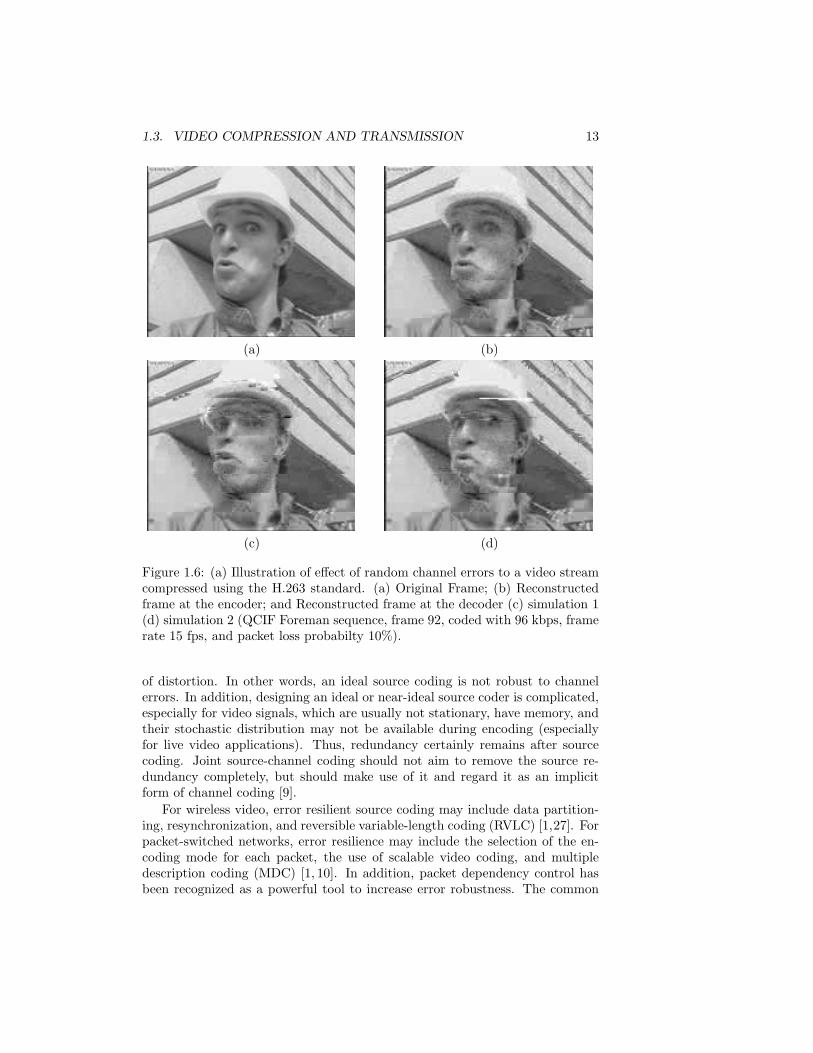
Figure 1.6: (a) Illustration of effect of random channel errors to a video streamcompressed using the H.263 standard. (a) Original Frame; (b) Reconstructedframe at the encoder; and Reconstructed frame at the decoder (c) simulation 1(d) simulation 2 (QCIF Foreman sequence, frame 92, coded with 96 kbps, framerate 15 fps, and packet loss probabilty 10%).
of distortion. In other words, an ideal source coding is not robust to channelerrors. In addition, designing an ideal or near-ideal source coder is complicated,especially for video signals, which are usually not stationary, have memory, andtheir stochastic distribution may not be available during encoding (especiallyfor live video applications). Thus, redundancy certainly remains after sourcecoding. Joint source-channel coding should not aim to remove the source re-dundancy completely, but should make use of it and regard it as an implicitform of channel coding [9].
For wireless video, error resilient source coding may include data partition-ing, resynchronization, and reversible variable-length coding (RVLC) [1,27]. Forpacket-switched networks, error resilience may include the selection of the en-coding mode for each packet, the use of scalable video coding, and multipledescription coding (MDC) [1, 10]. In addition, packet dependency control hasbeen recognized as a powerful tool to increase error robustness. The common
14CHAPTER 1. JOINT SOURCE-CHANNEL CODING FOR VIDEO COMMUNICATIONS
methods of packet dependency control are long-term memory (LTM) predic-tion for MBs, reference picture selection (RPS), intra-MB insertion, and videoredundancy coding (VRC) [30].
Layered video coding produces a hierarchy of bitstreams, where the differentparts of an encoded stream have unequal contributions to the overall quality.Layered coding has inherent error resilience benefits, especially if the layeredproperty can be exploited in transmission, where, for example, available band-width is partitioned to provide unequal error protection (UEP) for differentlayers with different importance. This approach is commonly referred to aslayered coding with transport prioritization [31].
Mode selection refers to the choice between temporal prediction (Inter cod-ing) to encode a macro-block and encoding it independently of previous frames(Intra coding). Inter coding has higher compression efficiency and thus resultsin lower source coding distortion than Intra coding for the same bit budget.Intra coding, on the other hand, is more resilient to error propagation and thusresults in lower channel distortion. The gist of optimal mode selection methodis to find the trade-off between coding efficiency and error robustness.
Mode selection algorithms have traditionally focused on Single Frame BMCcoding (SF-BMC), i.e., they consider the case where the previous frame is de-fined as the reference for the current frame. Recently, there has been significantwork on mode selection using Multiple Frame BMC (MF-BMC). Unlike SF-BMC, these approaches choose the reference frame from a group of previousframes. MF-BMC techniques capitalize on the correlation between multipleframes to improve compression efficiency and increase error resilience.
1.4 Channel Coding
In this section, we discuss the channel coding techniques that are widely usedfor the transmission of images and video. Two basic techniques used for videotransmission are FEC and Automatic Repeat reQuest (ARQ). Each has its ownbenefits with regard to error robustness and network traffic load [32,33].
As the name indicates, FEC refers to techniques in which the sender adds ex-tra information known as check or parity information to the source informationin order to make the transmission more robust to channel errors; the receiveranalyzes the parity information to locate and correct errors. FEC techniqueshave become an important channel coding tool used in modern communica-tion systems. One advantage of FEC techniques is that they do not require afeedback channel. In addition, these techniques improve system performance atsignificantly lower cost than other techniques aiming to improve channel SNR,such as increased transmitter power or antenna gain [9].
Of the two error correction techniques, FEC is usually preferred in real-time video applications, because of the delay requirements of these applications.Also, ARQ may not be appropriate for multicast scenarios due to their inherentscalability problems [1, 11]. This is because retransmission typically benefitsonly a small portion of receivers while all others wait unproductively, resulting in
1.4. CHANNEL CODING 15
poor throughput. For these reasons, FEC-based techniques are currently underconsideration by the Internet Engineering Task Force (IETF) as a proposedstandard in supporting error resilience [34].
The error detection/correction capability of FEC is limited due to the re-strictions on the block-size dictated by the application’s delay constraints. Inaddition, the appropriate level of FEC usually depends heavily on the accurateestimation of the channel’s behavior. ARQ, on the other hand, can automat-ically adapt to the channel loss characteristics by transmitting only as manyredundant packets as are lost. Compared to FEC, ARQ can usually achieve alevel closer to channel capacity. Of course, the tradeoff is that larger delays areintroduced by ARQ. Thus, if the application has a relatively loose end-to-enddelay constraint (e.g., on-demand video streaming), ARQ may be better suited.Even for real-time applications, delay constrained application-layer ARQ hasbeen shown to be useful in some situations [22,32,35].
1.4.1 Forward error correction
The choice of the FEC method depends on the requirements of the systemand the nature of the channel. For video communications, FEC can usuallybe applied across packets (at the application or transport layer) and withinpackets (at the link layer) [36]. In inter-packet FEC, parity packets are usuallygenerated in addition to source packets to perform cross-packet FEC, which isusually achieved by erasure codes. At the link layer, redundant bits are addedwithin a packet to perform intra-packet prediction from bit errors.
The Internet can usually be modeled as a packet erasure channel [11,21,22].For Internet applications, many researchers have considered using erasure codesto recover packet losses [37]. With such approaches, a video stream is first parti-tioned into segments and each segment is packetized into a group of m packets.A block code is then applied to the m packets to generate additional l redun-dant packets (also called parity packets) resulting in a n-packet block, wheren = m+ l. With such a code, the receiver can recover the original m packets if asufficient number of packets in the block are received. The most commonly stud-ied erasure codes are Reed-Solomon (RS) codes [38]. They have good erasurecorrecting properties and are widely used in practice, as for example in storagedevices (VCD, DVD), mobile communications, satellite communications, digitaltelevision, and high speed modems (ADSL) [37]. Another class of erasure codesthat have recently been considered for network applications are Tornado codes,which have slightly worse erasure protecting properties, but can be encoded anddecoded much more efficiently than RS codes [31].
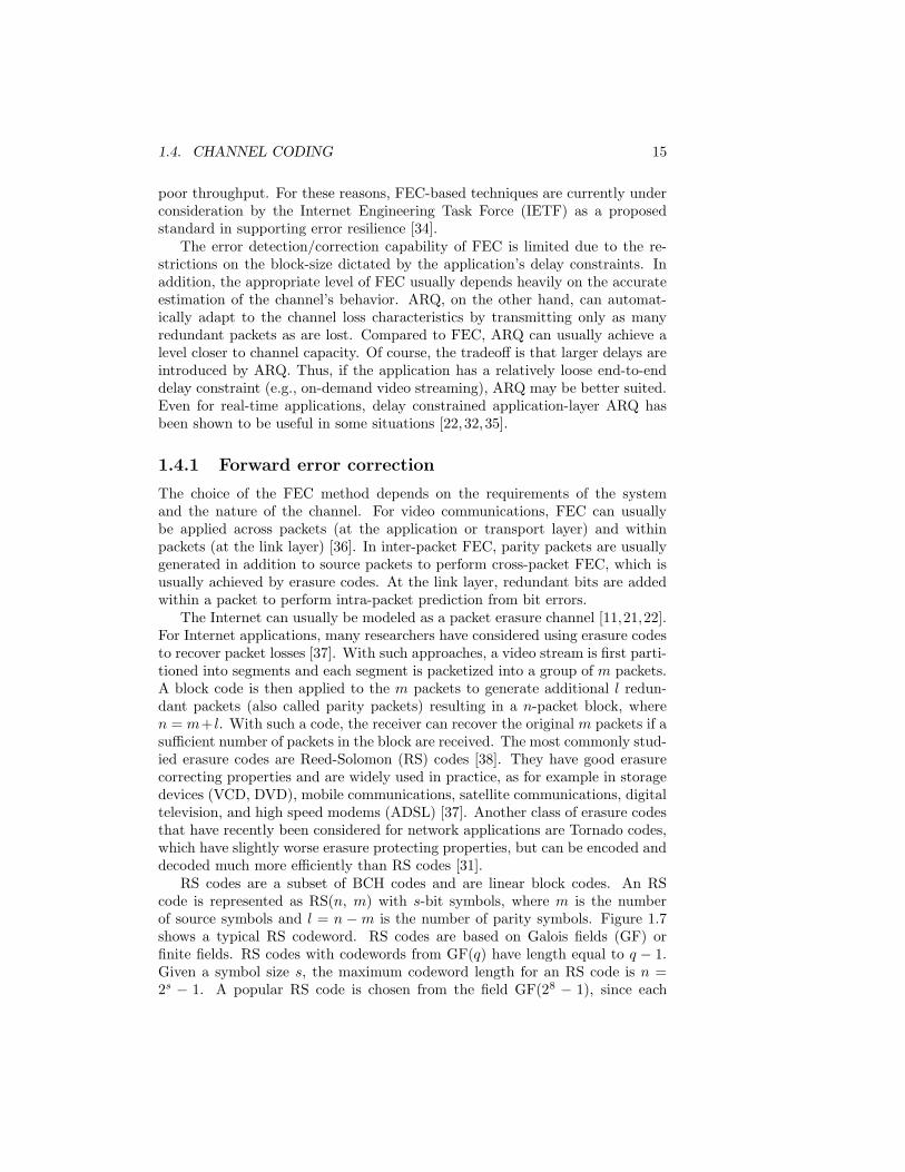
RS codes are a subset of BCH codes and are linear block codes. An RScode is represented as RS(n, m) with s-bit symbols, where m is the numberof source symbols and l = n − m is the number of parity symbols. Figure 1.7shows a typical RS codeword. RS codes are based on Galois fields (GF) orfinite fields. RS codes with codewords from GF(q) have length equal to q − 1.Given a symbol size s, the maximum codeword length for an RS code is n =2s − 1. A popular RS code is chosen from the field GF(28 − 1), since each
16CHAPTER 1. JOINT SOURCE-CHANNEL CODING FOR VIDEO COMMUNICATIONS
DATA Parity
n=m+l m l
Figure 1.7: Illustrate of RS(n,m) codeword
symbol can be represented as a byte. For the detailed encoding and decodingoperation rules and implementations in hardware or software, refer to [39, 40]for a comprehensive tutorial.
An RS code can be used to correct both errors and erasures (an erasureoccurs when the position of an error symbol is known). An RS(n, m) decodercan correct up to (n−m)/2 errors or up to (n−m) erasures, regardless of whichsymbols are lost. The code rate of an RS(n, m) code is defined as m/n. Theprotection capability of an RS code depends on the block size n and the coderate m/n. These are limited by the extra delay introduced by FEC. The blocksize can be determined based on the end-to-end system delay constraints.
The channel errors in wired links are typically in the form of packet erasures,so an RS(n, m) code applied across packets can recover up to (n − m) lostpackets. Thus, the block failure probability (i.e., the probability that at leastone of the original m packets is in error) is Pb(n,m) = 1 −
∑n−mj=0 P (n, j),
where P (n, j) represents the probability of j errors out of n transmissions. Asfor wireless channels, channel coding is applied within each packet to provideprotection. Source bits in a packet are first partitioned into m symbols, andthen (n−m) parity symbols are generated and added to the source bits to forma block. In this case, the noisy wireless channel causes symbol errors withinpackets (but not erasures). As a result, the block error probability for an RS
(n, m) code can be expressed as Pb(n,m) = 1 −∑(n−m)/2
j=0 P (n, j).Another popular type of codes used to perform intra-packet FEC is Rate-
Compatible Punctured Convolutional (RCPC) codes [36], first introduced in[41]. These codes are easy to implement, and have the property of being ratecompatible, i.e., a lower rate channel code is a prefix of a higher rate channelcode. A family of RCPC codes is described by the mother code of rate 1/N andmemory M with generator tap matrix of dimension N ×(M +1). Together withN , the puncturing period G determines the range of code rates as R = G/(G+l),where l can vary between 1 and (N − 1)G. RCPC codes are punctured codes ofthe mother code with puncturing matrices a(l) = (aij(l)) (of dimension N ×G),with aij(l) ∈ (0, 1) and 0 denoting puncturing.
The decoding of convolutional codes is most commonly achieved throughthe Viterbi algorithm, which is a maximum-likelihood sequence estimation al-gorithm. The Viterbi upper bound for the bit error probability is given by
pb ≤1
G
∞∑
d=dfree
cdpd
1.4. CHANNEL CODING 17
where dfree is the free distance of the convolutional code, which is defined as theminimum Hamming distance between two distinct codewords, pd the probabilitythat the wrong path at distance d is selected, and cd the number of paths atHamming distance d from the all-zero path. dfree and cd are parameters of theconvolutional code, while pd depends on the type of decoding (soft or hard) andthe channel. Both the theoretical bounds of BER and the simulation methodsto calculate BER for RCPC codes can be found in [40,41].
1.4.2 Retransmission
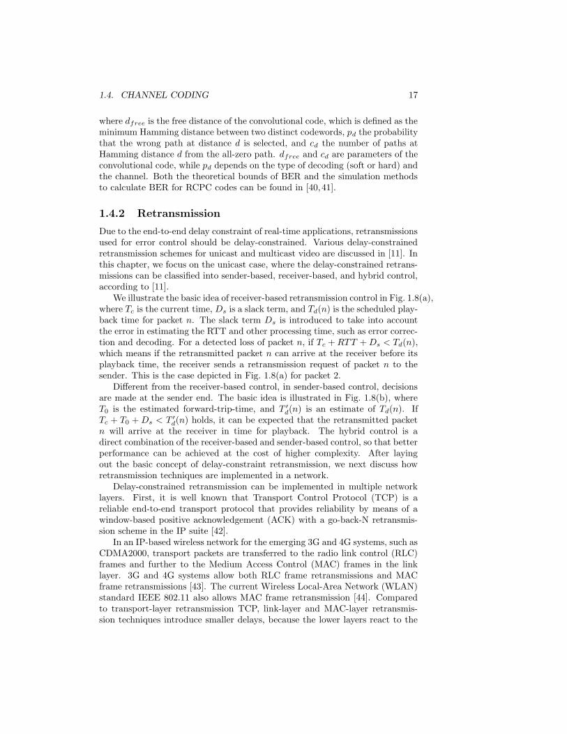
Due to the end-to-end delay constraint of real-time applications, retransmissionsused for error control should be delay-constrained. Various delay-constrainedretransmission schemes for unicast and multicast video are discussed in [11]. Inthis chapter, we focus on the unicast case, where the delay-constrained retrans-missions can be classified into sender-based, receiver-based, and hybrid control,according to [11].
We illustrate the basic idea of receiver-based retransmission control in Fig. 1.8(a),where Tc is the current time, Ds is a slack term, and Td(n) is the scheduled play-back time for packet n. The slack term Ds is introduced to take into accountthe error in estimating the RTT and other processing time, such as error correc-tion and decoding. For a detected loss of packet n, if Tc + RTT + Ds < Td(n),which means if the retransmitted packet n can arrive at the receiver before itsplayback time, the receiver sends a retransmission request of packet n to thesender. This is the case depicted in Fig. 1.8(a) for packet 2.
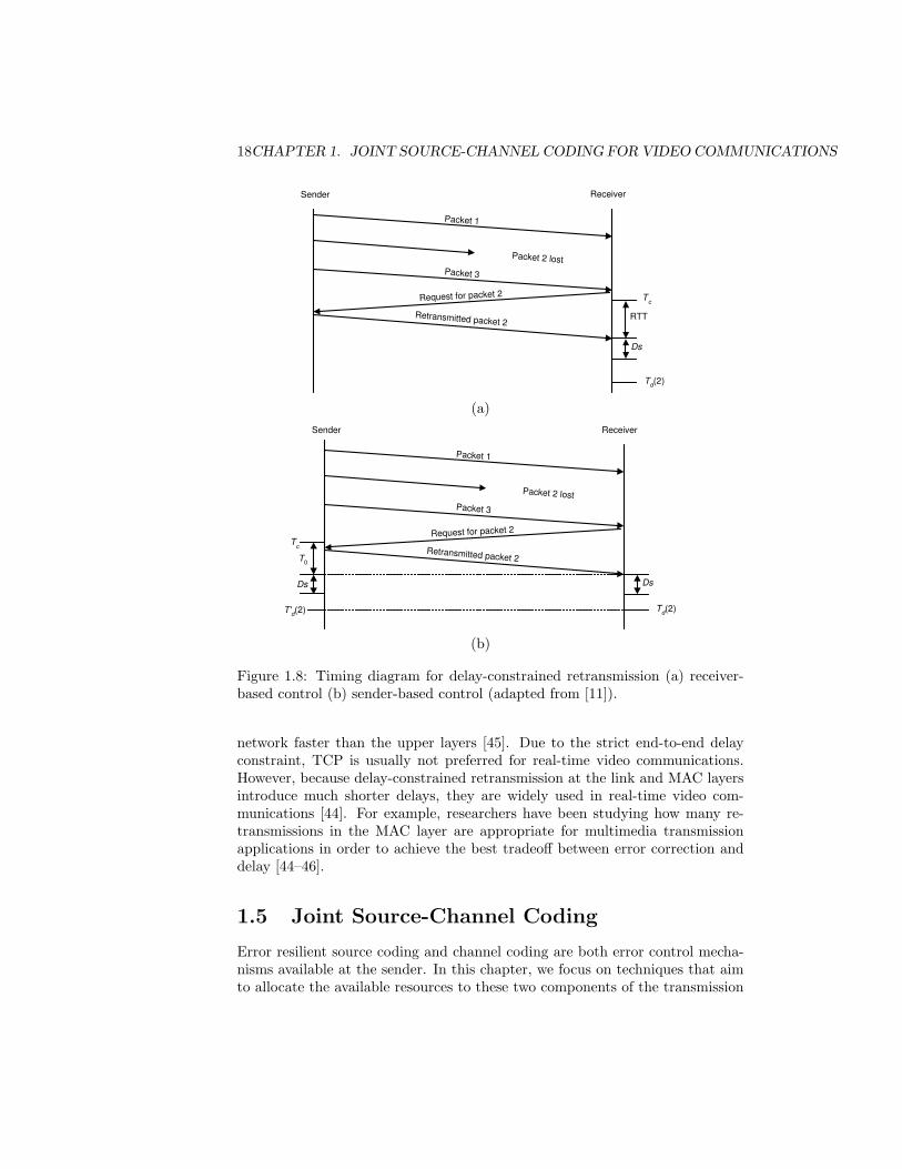
Different from the receiver-based control, in sender-based control, decisionsare made at the sender end. The basic idea is illustrated in Fig. 1.8(b), whereT0 is the estimated forward-trip-time, and T ′
d(n) is an estimate of Td(n). IfTc + T0 + Ds < T ′
d(n) holds, it can be expected that the retransmitted packetn will arrive at the receiver in time for playback. The hybrid control is adirect combination of the receiver-based and sender-based control, so that betterperformance can be achieved at the cost of higher complexity. After layingout the basic concept of delay-constraint retransmission, we next discuss howretransmission techniques are implemented in a network.
Delay-constrained retransmission can be implemented in multiple networklayers. First, it is well known that Transport Control Protocol (TCP) is areliable end-to-end transport protocol that provides reliability by means of awindow-based positive acknowledgement (ACK) with a go-back-N retransmis-sion scheme in the IP suite [42].
In an IP-based wireless network for the emerging 3G and 4G systems, such asCDMA2000, transport packets are transferred to the radio link control (RLC)frames and further to the Medium Access Control (MAC) frames in the linklayer. 3G and 4G systems allow both RLC frame retransmissions and MACframe retransmissions [43]. The current Wireless Local-Area Network (WLAN)standard IEEE 802.11 also allows MAC frame retransmission [44]. Comparedto transport-layer retransmission TCP, link-layer and MAC-layer retransmis-sion techniques introduce smaller delays, because the lower layers react to the
18CHAPTER 1. JOINT SOURCE-CHANNEL CODING FOR VIDEO COMMUNICATIONS
Sender Receiver
Packet 1
Packet 3
Request for packet 2
Packet 2 lost
Retransmitted packet 2
T c
T d (2 )
RTT
Ds
(a)
Sender Receiver
Packet 1
Packet 3
Request for packet 2
Packet 2 lost
Retransmitted packet 2
T c
T d ( 2 )
Ds
T' d ( 2 )
Ds
T 0
(b)
Figure 1.8: Timing diagram for delay-constrained retransmission (a) receiver-based control (b) sender-based control (adapted from [11]).
network faster than the upper layers [45]. Due to the strict end-to-end delayconstraint, TCP is usually not preferred for real-time video communications.However, because delay-constrained retransmission at the link and MAC layersintroduce much shorter delays, they are widely used in real-time video com-munications [44]. For example, researchers have been studying how many re-transmissions in the MAC layer are appropriate for multimedia transmissionapplications in order to achieve the best tradeoff between error correction anddelay [44–46].
1.5 Joint Source-Channel Coding
Error resilient source coding and channel coding are both error control mecha-nisms available at the sender. In this chapter, we focus on techniques that aimto allocate the available resources to these two components of the transmission
1.5. JOINT SOURCE-CHANNEL CODING 19
chain in order to provide the best end-to-end video quality.As a preliminary matter of a formal approach to problem solving, several
factors need to be clarified. An appropriate system performance evaluationmetric should first be selected. Second, the constraints need to be specified.Third, a model of the relationship between the system performance metric andthe set of adaptation parameters needs to be established. The final step is tofind the best combination of adaptation parameters that maximizes the systemperformance while meeting the required constraints. Keeping those four stepsin mind, we next present a formal approach to formulate and provide solutionsto the joint source-channel coding problem.
1.5.1 Problem formulation
A commonly used criterion for the evaluation of the system performance is theexpected distortion. The expectation is required due to the stochastic natureof the channel. As shown in (1.4), in calculating the expected distortion foreach source packet, the two distortion terms, E[DR,k] and E[DL,k], and the lossprobability for the source packet ρk need to be determined. The two distortionterms depend on the source coding parameters such as quantization stepsizeand prediction mode, as well as error concealment schemes used at the decoder.The relationship between the source packet loss probability and channel charac-teristics depends on the specific packetization scheme, the channel model, andthe adaptation parameters chosen.
Let S be the set of source coding parameters, and C the channel codingparameter. Let s = {s1, ..., sM} ∈ SM and c = {c1, ..., cM} ∈ CM denote,respectively, the vector of source coding parameters and channel coding param-eters for the M packets in one video frame or a group of frames. The generalformulation then is to minimize the total expected distortion for the frame(s),given the corresponding bit rate constraint [47], i.e.,
min{s∈SM ,c∈CM}
E[D(s, c)]
s.t. R(s, c) ≤ R0,(1.5)
where R(s, c) represents the total number of bits used for both source andchannel coding, and R0 the bit rate constraint for the frame(s). The bit rateconstraint is usually obtained based on the estimated channel throughput. Notethat since video packets are usually of different importance, the optimal solutionwill result in an UEP cross video packets.
As shown in Fig. 1.6, with the same channel characteristics, different simu-lations may diverge to a large extent with regard to reconstruction quality. Anovel approach called VAPOR (Variance-Aware per-Pixel Optimal Resource al-location) is proposed in [48] to deal with this. Besides the widely used expecteddistortion matric, the VAPOR approach aims to limit error propagation fromrandom channel errors by accounting for both the expected value and the vari-ance of the end-to-end distortion when allocating source and channel resources.By accounting for the variance of the distortion, this approach increases the
20CHAPTER 1. JOINT SOURCE-CHANNEL CODING FOR VIDEO COMMUNICATIONS
reliability of the system by making it more likely that what the end-user sees,closely resembles the mean end-to-end distortion calculated at the transmitter.
This type of constrained problem can be solved in general using the La-grangian relaxation method; that is, instead of the original problem, the follow-ing problem is solved
min{s∈SM ,c∈CM}
J(s, c, λ) = min{s∈SM ,c∈CM}
{E[D(s, c)] + λR(s, c)}, (1.6)
The solution of (1.5) can be obtained, within a convex hull approximation, bysolving (1.6) with the appropriate choice of the Lagrange multiplier, λ ≥ 0, sothat the bit rate constraint is satisfied. The difficulty in solving the resultingrelaxed problem depends on the complexity of the inter-packet dependencies.Depending on the nature of such dependencies, an iterative descent algorithmbased on the method of alternating variables for multivariate minimization [49]or a deterministic dynamic programming algorithm [50] can be employed toefficiently solve the minimization problem.
The JSCC problem formulation (1.5) is general for the fact that both thesource coding and channel coding can take a variety of forms, depending on thespecific application. For example, when FEC is utilized, the packet loss probabil-ity becomes a function of the FEC choice. The details of this model will dependon how transport packets are formed from the available video packets [51]. Inaddition to FEC, retransmission-based error control may be used in the formof ARQ protocols. In this case, the decision whether to retransmit a packet orto send a new one forms another channel coding parameter, which also affectsthe probability of loss as well as the transmission delay. When considering thetransmission of video over a network, a more general joint source-channel cod-ing scheme may cover modulation and demodulation [52], power adaptation [23],packet scheduling [53], and data rate adaptation [53]. These adaptation com-ponents can all be regarded as channel coding parameters. Source coding pa-rameters, on the other hand, can be in the form of mode selection [10, 23, 51],packetization [44], intra-MB refreshment rate [28], and entropy coding mecha-nism [6]. By solving problem (1.5) and selecting the source coding and channelcoding parameters within their sets, we can obtain the optimal tradeoff amongall those adaptation components. We next provide examples of the applicationsof JSCC to video transmission in different network infrastructures.
1.5.2 Internet video transmission
For video transmission over the Internet, channel coding usually takes the formof FEC and/or ARQ at the transport layer. FEC is usually preferred for appli-cations that impose a relatively short end-to-end delay constraint. Joint sourcecoding and FEC has been extensively studied in the literature [24, 37, 54–56].Such studies focus on the determination of the optimal bit allocation betweensource coding and FEC. In [57], the authors introduced the integrated jointsource-channel coding (IJSCC) framework, where error resilient source coding,
1.5. JOINT SOURCE-CHANNEL CODING 21
channel coding, and error concealment are jointly considered in a tractable op-timization setting. In using the IJSCC framework, an R-D optimized hybriderror control scheme has been presented in [58], which results in the optimalallocation of bits among source, FEC, and ARQ.
Joint source coding and FEC
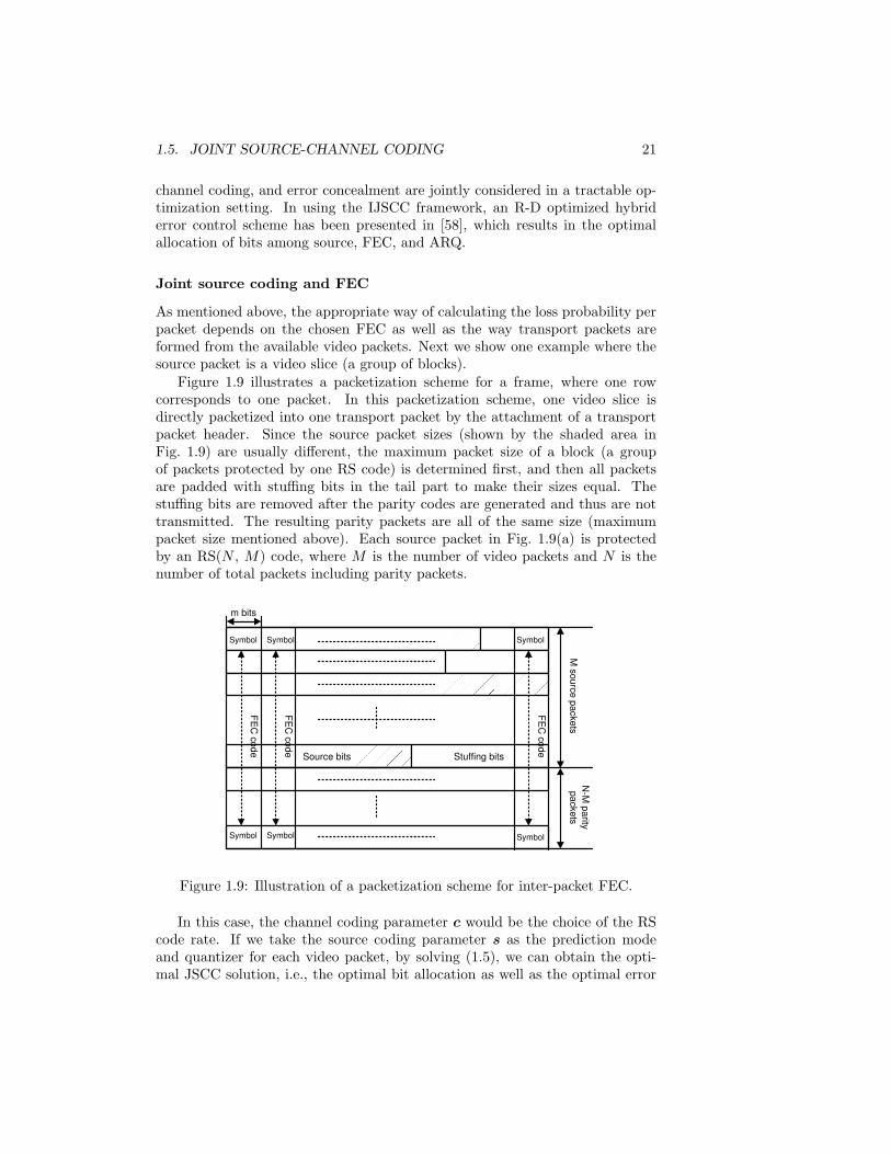
As mentioned above, the appropriate way of calculating the loss probability perpacket depends on the chosen FEC as well as the way transport packets areformed from the available video packets. Next we show one example where thesource packet is a video slice (a group of blocks).
Figure 1.9 illustrates a packetization scheme for a frame, where one rowcorresponds to one packet. In this packetization scheme, one video slice isdirectly packetized into one transport packet by the attachment of a transportpacket header. Since the source packet sizes (shown by the shaded area inFig. 1.9) are usually different, the maximum packet size of a block (a groupof packets protected by one RS code) is determined first, and then all packetsare padded with stuffing bits in the tail part to make their sizes equal. Thestuffing bits are removed after the parity codes are generated and thus are nottransmitted. The resulting parity packets are all of the same size (maximumpacket size mentioned above). Each source packet in Fig. 1.9(a) is protectedby an RS(N , M) code, where M is the number of video packets and N is thenumber of total packets including parity packets.� � �� � �
� � � �� � � �
� � �� � �
Source bits Stuffing bits
m bits
M source packets
N-M
parity packets
FEC
code
FEC
code
FEC
code
Symbol Symbol
Symbol Symbol
Symbol
Symbol
Figure 1.9: Illustration of a packetization scheme for inter-packet FEC.
In this case, the channel coding parameter c would be the choice of the RScode rate. If we take the source coding parameter s as the prediction modeand quantizer for each video packet, by solving (1.5), we can obtain the opti-mal JSCC solution, i.e., the optimal bit allocation as well as the optimal error
22CHAPTER 1. JOINT SOURCE-CHANNEL CODING FOR VIDEO COMMUNICATIONS
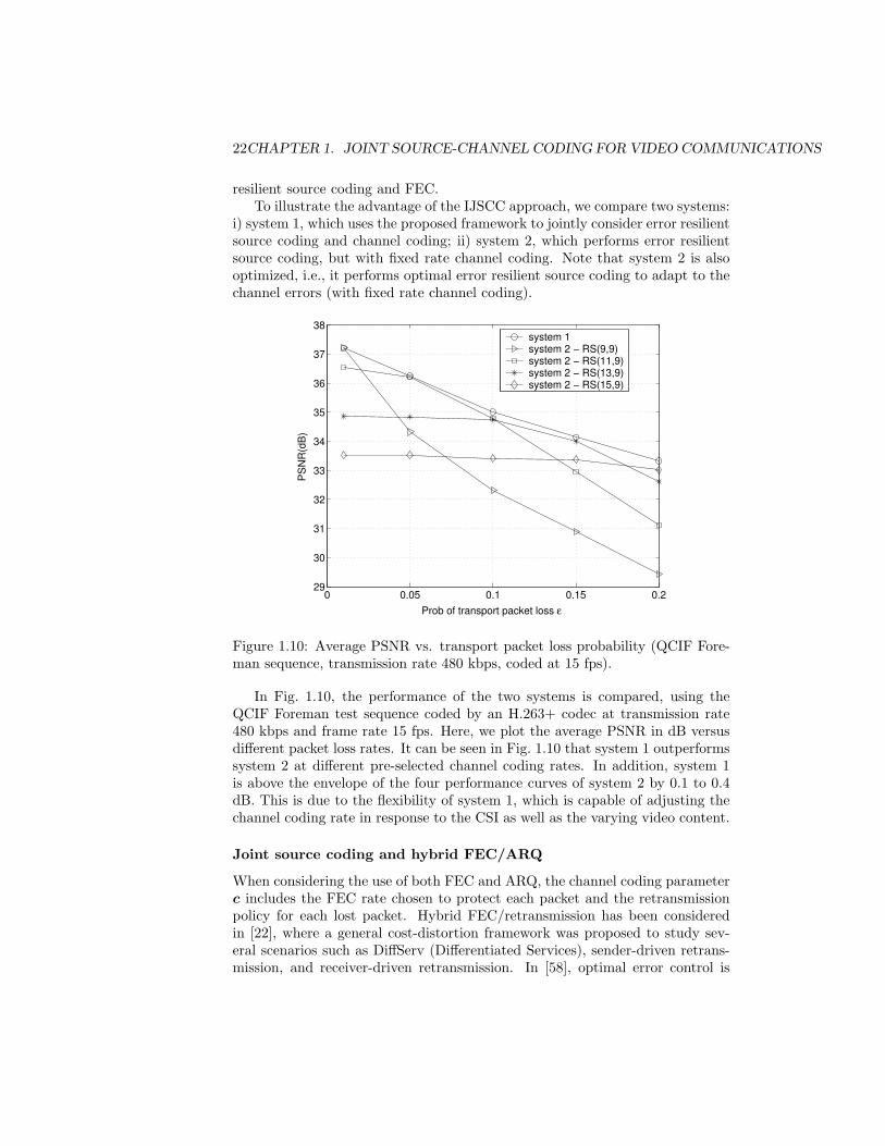
resilient source coding and FEC.To illustrate the advantage of the IJSCC approach, we compare two systems:
i) system 1, which uses the proposed framework to jointly consider error resilientsource coding and channel coding; ii) system 2, which performs error resilientsource coding, but with fixed rate channel coding. Note that system 2 is alsooptimized, i.e., it performs optimal error resilient source coding to adapt to thechannel errors (with fixed rate channel coding).
0 0.05 0.1 0.15 0.229
30
31
32
33
34
35
36
37
38
Prob of transport packet loss ε
PS
NR
(dB
)
system 1system 2 − RS(9,9)system 2 − RS(11,9)system 2 − RS(13,9)system 2 − RS(15,9)
Figure 1.10: Average PSNR vs. transport packet loss probability (QCIF Fore-man sequence, transmission rate 480 kbps, coded at 15 fps).
In Fig. 1.10, the performance of the two systems is compared, using theQCIF Foreman test sequence coded by an H.263+ codec at transmission rate480 kbps and frame rate 15 fps. Here, we plot the average PSNR in dB versusdifferent packet loss rates. It can be seen in Fig. 1.10 that system 1 outperformssystem 2 at different pre-selected channel coding rates. In addition, system 1is above the envelope of the four performance curves of system 2 by 0.1 to 0.4dB. This is due to the flexibility of system 1, which is capable of adjusting thechannel coding rate in response to the CSI as well as the varying video content.
Joint source coding and hybrid FEC/ARQ
When considering the use of both FEC and ARQ, the channel coding parameterc includes the FEC rate chosen to protect each packet and the retransmissionpolicy for each lost packet. Hybrid FEC/retransmission has been consideredin [22], where a general cost-distortion framework was proposed to study sev-eral scenarios such as DiffServ (Differentiated Services), sender-driven retrans-mission, and receiver-driven retransmission. In [58], optimal error control is
1.5. JOINT SOURCE-CHANNEL CODING 23
performed by jointly considering source coding with hybrid FEC and sender-driven application-layer selective retransmission. This study is carried out withthe use of (1.5), with a sliding window scheme in which lost packets are selec-tively retransmitted according to a rate-distortion optimized policy. Simulationsin [58] show that the performance advantage in using either FEC or selectiveretransmission depends on the packet loss rate and the round-trip time. In thatwork, the proposed hybrid FEC and selective retransmission approach is ableto derive the benefits of both approaches by adapting the type of error controlbased on the channel characteristics.
A receiver-driven hybrid FEC/Pseudo-ARQ mechanism is proposed for In-ternet multimedia multicast in [33]. In that work, the sender multicasts all thesource layers and all the channel layers (parity packets obtained by using RScoding similar to what we have discussed in the previous section) to separatemulticast groups. Each user computes the optimal allocation of the availablebit rate between source and channel layers based on its estimated channel band-width and packet loss probability, and joins the corresponding multicast group.This is achieved through a pseudo-ARQ system, in which the sender continu-ously transmits delayed parity packets to additional multicast group, and thereceivers can join or leave a multicast group to retrieve the lost information upto a given delay bound. Such a system looks like ordinary ARQ to the receiverand an ordinary multicast to the sender. This can be characterized as JSCCwith receiver feedback. More specifically, the optimal JSCC is obtained by solv-ing (1.5) at the receiver side, where the source coding parameter is the numberof source layers, and the channel coding parameter is the number of channellayers.
1.5.3 Wireless video transmission
Wireless video communications is a broad, active, and well-studied field of re-search [59, 60]. Recently, several adaptation techniques have been proposedspecifically for energy efficient wireless video communications. A trend in thisfield of research is the joint adaptation of source coding and transmission pa-rameters based on the time-varying source content and channel conditions. Thegeneral JSCC framework (1.5) therefore encompasses these techniques with anadditional constraint on the total energy consumed in delivering the video se-quence to the end-user. Correspondingly, the channel coding parameters wouldcover more general channel adaptation parameters such as the transmission rate,physical-layer modulation modes, and the transmitter power.
Joint source coding and FEC
As with Internet video transmission, the problem of joint source coding andFEC for wireless video communications focuses on the optimal bit allocationbetween source and channel coding by solving (1.5). The difference is that dueto the different type of channel errors (bit errors) in a wireless channel, FEC
24CHAPTER 1. JOINT SOURCE-CHANNEL CODING FOR VIDEO COMMUNICATIONS
is achieved by adding redundant bits within packets to provide intra-packetprotection. RCPC and RS codes are widely used in this case.
Optimal bit allocation has been studied in [55] based on a subband videocodec. A Binary Symmetric Channel (BSC) with Additive White GaussianNoise (AWGN) model have been considered for simulations. The source codingparameters are the bit rate of the source subband and the channel coding pa-rameters are the FEC parameter for each subband. A similar problem has beenstudied for video transmission over a Rayleigh fading wireless channel in [24]based on an H.263+ SNR scalable video codec. In that work, Universal R-DCharacteristics (URDC) of the source scheme are employed to make the opti-mization tractable. Both works used RCPC codes to achieve the intra-packetFEC.
RS codes are used to perform channel coding in [28] for video transmissionover a random BSC. Based on their proposed RD model, the source codingparameter is the intra-MB refreshment rate and the channel coding parameteris the channel rate.
Joint source coding and power adaptation
Joint source coding and power allocation techniques account for the varyingerror sensitivity of video packets by adapting the transmission power per packetbased on the source content and the CSI. In other words, these techniques usetransmission power as an UEP mechanism. In this case, the channel codingparameter is the power level for each video packet. Video transmission overCDMA networks using a scalable source coder (3-D SPIHT), along with errorcontrol and power allocation is considered in [61]. A scheme for allocatingsource rate and transmission power under bandwidth constraints is consideredin [62]. In [23], optimal mode and quantizer selection is considered jointly withtransmission power allocation.
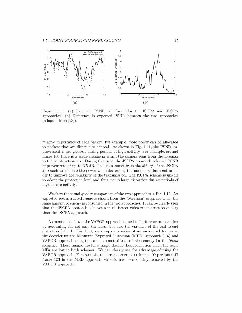
To illustrate some advantages of joint adaptation of the source coding andtransmission parameters in wireless video transmission systems, we present ex-perimental results which are discussed in detail in [23]. We compare a jointsource coding and transmission power allocation (JSCPA) approach, i.e., theapproach described by (1.5), with an independent source coding and power al-location (ISCPA) approach in which S and C are independently adapted. InFig. 1.11, we plot the expected PSNR per frame of both approaches for theForeman test sequence coded at 15 fps. It is important to note that both ap-proaches use the same transmission energy and delay per frame.
As shown in Fig. 1.11, the JSCPA approach achieves significantly higherquality (expected PSNR) per frame than the ISCPA approach. Because thevideo encoder and the transmitter operate independently in the ISCPA ap-proach, the relative importance of each packet, i.e., their contribution to thetotal distortion, is unknown to the transmitter. Therefore, the transmittertreats each packet equally and adapts the power in order to maintain a constantprobability of packet loss. The JSCPA approach, on the other hand, is ableto adapt the power per packet, and thus the probability of loss, based on the
1.5. JOINT SOURCE-CHANNEL CODING 25
0 50 100 15022
24
26
28
30
32
34
Frame Number
Exp
ecte
d P
SN
R
ISCPA approachJSCPA approach
(a)
0 50 100 1500
0.5
1
1.5
2
2.5
3
3.5
4
Frame Number
Exp
ecte
d P
SN
R D
iffer
ence
(b)
Figure 1.11: (a) Expected PSNR per frame for the ISCPA and JSCPAapproaches; (b) Difference in expected PSNR between the two approaches(adopted from [23]).
relative importance of each packet. For example, more power can be allocatedto packets that are difficult to conceal. As shown in Fig. 1.11, the PSNR im-provement is the greatest during periods of high activity. For example, aroundframe 100 there is a scene change in which the camera pans from the foremanto the construction site. During this time, the JSCPA approach achieves PSNRimprovements of up to 3.5 dB. This gain comes from the ability of the JSCPAapproach to increase the power while decreasing the number of bits sent in or-der to improve the reliability of the transmission. The ISCPA scheme is unableto adapt the protection level and thus incurs large distortion during periods ofhigh source activity.
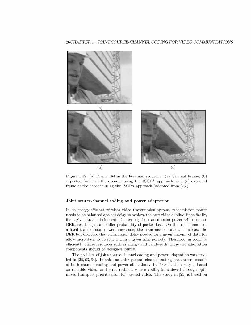
We show the visual quality comparison of the two approaches in Fig. 1.12. Anexpected reconstructed frame is shown from the “Foreman” sequence when thesame amount of energy is consumed in the two approaches. It can be clearly seenthat the JSCPA approach achieves a much better video reconstruction qualitythan the ISCPA approach.
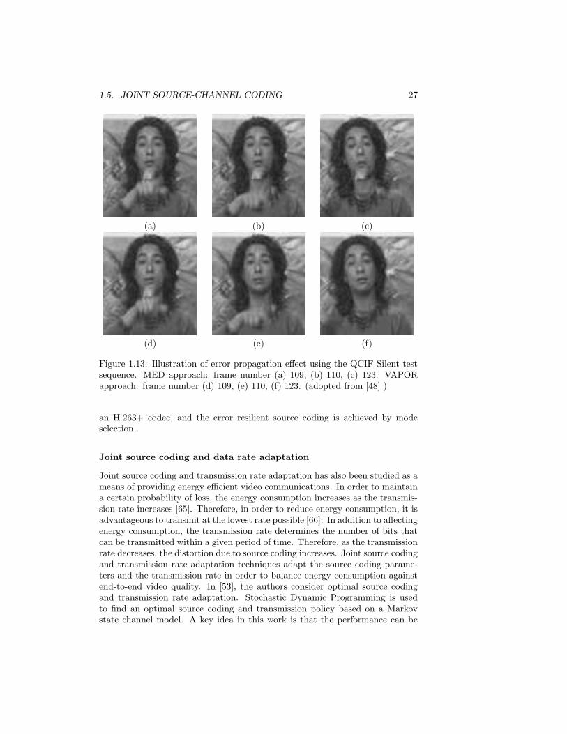
As mentioned above, the VAPOR approach is used to limit error propagationby accounting for not only the mean but also the variance of the end-to-enddistortion [48]. In Fig. 1.13, we compare a series of reconstructed frames atthe decoder for the Minimum Expected Distortion (MED) approach (1.5) andVAPOR approach using the same amount of transmission energy for the Silentsequence. These images are for a single channel loss realization when the sameMBs are lost in both schemes. We can clearly see the advantage of using theVAPOR approach. For example, the error occurring at frame 109 persists utillframe 123 in the MED approach while it has been quickly removed by theVAPOR approach.
26CHAPTER 1. JOINT SOURCE-CHANNEL CODING FOR VIDEO COMMUNICATIONS
(a)
(b) (c)
Figure 1.12: (a) Frame 184 in the Foreman sequence. (a) Original Frame; (b)expected frame at the decoder using the JSCPA approach; and (c) expectedframe at the decoder using the ISCPA approach (adopted from [23]).
Joint source-channel coding and power adaptation
In an energy-efficient wireless video transmission system, transmission powerneeds to be balanced against delay to achieve the best video quality. Specifically,for a given transmission rate, increasing the transmission power will decreaseBER, resulting in a smaller probability of packet loss. On the other hand, fora fixed transmission power, increasing the transmission rate will increase theBER but decrease the transmission delay needed for a given amount of data (orallow more data to be sent within a given time-period). Therefore, in order toefficiently utilize resources such as energy and bandwidth, those two adaptationcomponents should be designed jointly.
The problem of joint source-channel coding and power adaptation was stud-ied in [25, 63, 64]. In this case, the general channel coding parameters consistof both channel coding and power allocations. In [63, 64], the study is basedon scalable video, and error resilient source coding is achieved through opti-mized transport prioritization for layered video. The study in [25] is based on
1.5. JOINT SOURCE-CHANNEL CODING 27
(a) (b) (c)
(d) (e) (f)
Figure 1.13: Illustration of error propagation effect using the QCIF Silent testsequence. MED approach: frame number (a) 109, (b) 110, (c) 123. VAPORapproach: frame number (d) 109, (e) 110, (f) 123. (adopted from [48] )
an H.263+ codec, and the error resilient source coding is achieved by modeselection.
Joint source coding and data rate adaptation
Joint source coding and transmission rate adaptation has also been studied as ameans of providing energy efficient video communications. In order to maintaina certain probability of loss, the energy consumption increases as the transmis-sion rate increases [65]. Therefore, in order to reduce energy consumption, it isadvantageous to transmit at the lowest rate possible [66]. In addition to affectingenergy consumption, the transmission rate determines the number of bits thatcan be transmitted within a given period of time. Therefore, as the transmissionrate decreases, the distortion due to source coding increases. Joint source codingand transmission rate adaptation techniques adapt the source coding parame-ters and the transmission rate in order to balance energy consumption againstend-to-end video quality. In [53], the authors consider optimal source codingand transmission rate adaptation. Stochastic Dynamic Programming is usedto find an optimal source coding and transmission policy based on a Markovstate channel model. A key idea in this work is that the performance can be
28CHAPTER 1. JOINT SOURCE-CHANNEL CODING FOR VIDEO COMMUNICATIONS
improved by allowing the transmitter to suspend or slow down transmissionsduring periods of poor channel conditions, as long as the delay constraints arenot violated.
1.6 Discussion
While application of Shannon’s separation theorem leads to the introductionof redundancy only during channel coding for achieving error-free transmission,this is not the case under real-time constraints. Redundancy needs to be intro-duced during both source and channel encoding in a judicious way. Furthermore,a well-designed decoder can recover some of the lost information utilizing error-concealment techniques. When a feedback channel is available, a retransmissionprotocol can be implemented, offering a different means for improving the errorresiliency of the video communication system.
In this chapter, joint source-channel coding (JSCC) for video communica-tions has been discussed. We have used the term “channel encoding” in a gen-eral way to include modulation and demodulation, power adaptation, packetscheduling, and data rate adaptation. We provided an overview of the state-of-the-art implementations of JSCC in various network infrastructures. Althoughthe most recent video coding standards H.263, MPEG4, and H.264 provide anumber of error resilient tools, there are a number of resource allocation prob-lems which need to be resolved in order to efficiently utilize such tools. Inaddition, there is a plethora of issues that need to be addressed by consideringnew system structures.
As mentioned earlier, cross-layer design is a general term, which encompassesJSCC, and represents the current state of the art. In order to efficiently utilizelimited network resources, the video transmission system needs to be adaptiveto the changing network conditions. In the traditional layered protocol stack,each layer is optimized or adapted to the changing network conditions indepen-dently. The adaptation, however, is very limited due to the limited conversationsbetween layers. Cross-layer design aims to improve the system’s overall perfor-mance by jointly considering multiple protocol layers. The studies on this topicso far not only show the necessity to employ the joint design of multiple layers,but also point out the future direction of network protocol suite developmentto better support video communications over the current best effort networks.
Cross-layer design is a powerful approach to account for different types ofchannel errors in a hybrid wireless/wireline network that consists of both wiredand wireless links. An initial investigation of this topic is described in [51],where lower layer adaptation includes inter-packet FEC at the transport layerand intra-packet FEC at the link layer, which are respectively used to combatpacket losses in the wired line and bit errors in the wireless link. Such channeladaptations are jointly designed with mode selection in source coding to achieveoptimal UEP, by solving (1.5).
Overall the topic addressed in this chapter does not represent mature tech-nology yet. Although technologies providing higher bit rates and lower error

1.6. DISCUSSION 29
rates are continuously being deployed, higher QoS will inevitably lead to higheruser demands of service, which for video applications translates to higher reso-lution images of higher visual quality.

30CHAPTER 1. JOINT SOURCE-CHANNEL CODING FOR VIDEO COMMUNICATIONS
Bibliography
[1] Y. Wang, G. Wen, S. Wenger, and A. K. Katsaggelos, “Review of errorresilience techniques for video communications,” IEEE Signal ProcessingMagazine, vol. 17, pp. 61–82, July 2000.
[2] C. E. Shannon, “Coding theorems for a discrete source with a fidelitycriterion,” IRE International Convention Records, pp. 142–163, 1959, Part4.
[3] C. E. Shannon, “A mathematical theory of communication,” Bell Syst.Tech. J. 27, pp. 379–423 and 623–656, July 1948.
[4] G. M. Schuster and A. K. Katsaggelos, Rate-Distortion Based Video Com-pression: Optimal Video Frame Compression and Object Boundary Encod-ing, Kluwer Academic Publishers, 1997.
[5] B. Sklar, Digital Communications: Fundamentals and Applications, En-glewood Cliffs, NJ: Prentice-Hall Inc., 2nd edition, 2001.
[6] N. Farvardin and V. Vaishampayan, “Optimal quantizer design for noisychannels: an approach to combined source-channel coding,” IEEE Trans.Inform. Theory, vol. IT-38, pp. 827–838, 1987.
[7] F. Farvardin, “A study of vector quantization for noisy channels,” IEEETrans. Inform. Theory., vol. 36, pp. 799–809, July 1990.
[8] A. Kurtenbach and P. Wintz, “Quantizing for noisy channels,” IEEETrans. Commun. Technol., vol. COM-17, pp. 291–302, Apr. 1969.
[9] R. E. Van Dyck and D. J. Miller, “Transport of wireless video using sep-arate, concatenated, and joint source-channel coding,” Proceedings of theIEEE, vol. 87, pp. 1734–1750, Oct. 1999.
[10] D. Wu, Y. T. Hou, B. Li, W. Zhu, Y.-Q. Zhang, and H. J. Chao, “An end-to-end approach for optimal mode selection in Internet video communication:theory and application,” IEEE J. Select. Areas Commun., vol. 18, no. 6,pp. 977–995, June 2000.
31
32 BIBLIOGRAPHY
[11] D. Wu, Y. T. Hou, and Y.-Q. Zhang, “Transporting real-time video over theInternet: Challenges and approaches,” Proc. IEEE, vol. 88, pp. 1855–1877,Dec. 2000.
[12] J. M. Shapiro, “Embedded image coding using zerotrees of wavelet co-efficients,” IEEE Trans. Signal Processing, vol. 41, pp. 3445–3463, Dec.1993.
[13] A. Said and W. Pearlman, “A new, fast, and efficient image codec basedon set partitioning in hierarchical trees,” IEEE Trans. on Circ. and Syst.for Video Techn., vol. 6, pp. 243–250, June 1996.
[14] JPEG-2000 VM3.1 A Software, ISO/IECJTC1/SC29/WG1 N1142, Jan.1999.
[15] K. Shen and E. J. Delp, “Wavelet based rate scalable video compression,”IEEE Trans. Circ. and Syst. for Video Techn., vol. 9, pp. 109–122, Feb.1999.
[16] Y.-Q. Zhang and S. Zafar, “Motion-compensated wavelet transform codingfor color video compression,” IEEE Trans. on Circ. and Syst. for VideoTechn., vol. 2, pp. 285–296, Sept. 1992.
[17] J. R. Ohm, “Three-dimensional subband coding with motion compensa-tion,” IEEE Trans. Image Proc., vol. 3, pp. 559–571, Sept. 1994.
[18] S. Choi and J. W. Woods, “Motion-compensated 3-D subband coding ofvideo,” IEEE Trans. Image Proc., vol. 8, pp. 155–167, Feb. 1999.
[19] A. Secker and D. Taubman, “Motion-compensated highly scalable videocompression using an adaptive 3D wavelet transform based on lifting,” inProc. IEEE International Conference on Image Processing (ICIP), Thes-saloniki, Greece, Oct. 2001.
[20] J.-R. Ohm, “Motion-compensated wavelet lifting filters with flexible adap-tation,” in Proceedings of Tyrrhenian International Workshop on DigitalCommunications, Capri, Italy, Sept. 2002.
[21] D. A. Eckhardt, An Internet-style approach to managing wireless link er-rors, Ph.D Thesis, Carnegie Mellon University, Pittsburgh, PA, May 2002.
[22] P. A. Chou and Z. Miao, “Rate-distortion optimized streaming of packe-tized media,” IEEE Trans. on Multimedia, 2001, Submitted.
[23] Y. Eisenberg, C. E. Luna, T. N. Pappas, R. Berry, and A. K. Katsaggelos,“Joint source coding and transmission power management for energy effi-cient wireless video communications,” IEEE Trans. on Circuits and Systemfor Video Technology, vol. 12, no. 6, pp. 411–424, June 2002.
BIBLIOGRAPHY 33
[24] L. P. Kondi, F. Ishtiaq, and A. K. Katsaggelos, “Joint source-channelcoding for motion-compensated DCT-based SNR scalable video,” IEEETrans on Image Processing, vol. 11, pp. 1043–1052, Sept. 2002.
[25] F. Zhai, Y. Eisenberg, T. N. Pappas, R. Berry, and A. K. Katsaggelos,“Joint source-channel coding and power allocation for energy efficient wire-less communications,” in Proc. 41st Allerton Conf. on Communication,Control and Computing, Otc. 2003.
[26] R. Zhang, S. L. Regunathan, and K. Rose, “Video coding with optimalinter/intra-mode switching for packet loss resilience,” IEEE J. Select. AreasCommun., vol. 18, pp. 966–976, June 2000.
[27] G. Cote, S. Shirani, and F. Kossentini, “Optimal mode selection and syn-chronization for robust video communications over error-prone networks,”IEEE J. Select. Areas Commun., vol. 18, pp. 952–965, June 2000.
[28] Z. He, J. Cai, and C. W. Chen, “Joint source channel rate-distortion anal-ysis for adaptive mode selection and rate control in wireless video coding,”IEEE Trans. Circ. and Syst. for Video Techn., vol. 12, pp. 511–523, June2002.
[29] T. Wiegand, N. Farber, and B. Girod, “Error-resilient video transmissionusing long-term memory motion-compensated prediction,” IEEE J. Select.Areas Commun., vol. 18, no. 6, pp. 1050–1062, June 2000.
[30] B. Girod, J. Chakareski, M. Kalman, Y. J. Liang, E. Setton, and R. Zhang,“Advances in network-adaptive video streaming,” in Proc. 2002 TyrrhenianInternational Workshop on Digital Communications, 2002, pp. 1–8.
[31] A. Albanese, J. Blomer, J. Edmonds, M. Luby, and M. Sudan, “Priorityencoding transmission,” IEEE Trans. Inform. Theory, vol. 42, pp. 1737–1744, Nov. 1996.
[32] F. Hartanto and H. R. Sirisena, “Hybrid error control mechanism for videotransmission in the wireless IP networks,” in Proc. of IEEE Tenth Work-shop on Local and Metropolitan Area Networks (LANMAN’99), Sydney,Australia, Nov. 1999, pp. 126–132.
[33] P. A. Chou, A. E. Mohr, A. Wang, and S. Mehrotra, “Error control forreceiver-driven layered multicast of audio and video,” IEEE Trans. Multi-media, pp. 108–122, March 2001.
[34] J. Rosenberg and H. Schulzrinne, “An RTP payload format for genericforward error correction,” Tech. Rep., Internet Engineering Task Force,Request for Comments (Proposed Standard) 2733, Dec. 1999.
[35] B. J. Dempsey, J. Liebeherr, and A. C. Weaver, “On retransmission-basederror control for continuous media traffic in packet-switched networks,”Computer Networks and ISDN Syst., vol. 28, pp. 719–736, Mar. 1996.
34 BIBLIOGRAPHY
[36] N. Celandroni and F. Pototı, “Maximizing single connection TCP goodputby trading bandwidth for BER,” Int. J. of Commun. Syst., vol. 16, pp.63–79, Feb. 2003.
[37] M. Gallant and F. Kossentini, “Rate-distortion optimized layered codingwith unequal error protection for robust Internet video,” IEEE Trans. onCirc. and Syst. for Video Techn., vol. 11, no. 3, pp. 357–372, March 2001.
[38] I. S. Reed and G. Solomon, “Polynomial codes over certain finite fields,”SIAM J. Applied Math., vol. 8, pp. 300–304, 1960.
[39] S. B. Wicker and V. K. Bhargava, Reed-Solomon Codes and Their Appli-cations, John Wiley & Sons Inc., Sept. 1999.
[40] J. G. Proakis, Digital Communications, McGraw-Hill, New York, Aug.2000.
[41] J. Hagenauer, “Rate-compatible punctured convolutional codes (RCPCcodes) and their applications,” IEEE Trans. Commun., vol. 36, pp. 389–400, Apr. 1988.
[42] Douglas E. Comer, Internetworking with TCP/IP, vol. 1, Prentice-Hall,Upper Saddle River, NJ, 1995.
[43] P. Luukkanen, Z. Rong, and L. Ma, “Performance of 1XTREME systemfor mixed voice and data communications,” in Proceedings IEEE Inf. Conf.Communications, Helsinki, Finland, June 2001, pp. 1411–1415.
[44] M. var der Schaar, S. Krishnamachari, S. Choi, and X. Xu, “Adaptivecross-layer protection strategies for robust scalable video transmission over802.11 WLANs,” IEEE J. Select. Areas Commun., vol. 21, pp. 1752–1763,Dec. 2003.
[45] A. Chockalingam and G. Bao, “Performance of TCP/RLP protocol stackon correlated fading DS-CDMA wireless links,” IEEE Trans. Veh. Tech.,vol. 49, pp. 28–33, Jan. 2000.
[46] H. Zheng, “Optimizing wireless multimedia transmissions through crosslayer design,” in Proc. IEEE, Baltimore, MD, July 2003, vol. 1, pp. 185–188.
[47] A. K. Katsaggelos, Y. Eisenberg, F. Zhai, R. Berry, and T. N. Pappas,“Advances in efficient resource allocation for packet-based real-time videotransmission,” Proceedings of the IEEE, Jan. 2005.
[48] Y. Eisenberg, F. Zhai, T. N. Pappas, R. Berry, and A. K. Katsaggelos,“VAPOR: Variance-aware per-pixel optimal resource allocation,” IEEETrans. Image Processing, 2005, To appear.
[49] R. Fletcher, Practical methods of optimization, New York: Wiley, 2ndedition, 1987.
BIBLIOGRAPHY 35
[50] D. P. Bertsekas, Dynamic Programming: Determinstistic and Stochasticmethods, Prentice-Hall, 1987.
[51] F. Zhai, Y. Eisenberg, T. N. Pappas, R. Berry, and A. K. Katsaggelos,“Rate-distortion optimized product code forward error correction for videotransmission over IP-based wireless networks,” in Proc. Int. Conf. Acous-tics, Speech and Signal Processing, Montreal, Canada, June 2004.
[52] Y. Pei ad J. W. Modestino, “Multi-layered video transmission over wirelesschannels using an adaptive modulation and coding scheme,” in Proc.2001IEEE Int. Conf. Image Processing, Thesaloniki, Greece, Oct. 2001.
[53] C. E. Luna, Y. Eisenberg, R. Berry, T. N. Pappas, and A. K. Katsaggelos,“Joint source coding and data rate adaption for energy efficient wirelessvideo streaming,” IEEE J. Select. Areas Commun., vol. 21, pp. 1710–1720,Dec. 2003.
[54] G. Davis and J. Danskin, “Joint source and channel coding for Internetimage transmission,” in Proc. SPIE and Conf. Wavelet Applications ofDigital Image Processing XIX, Denver, CO, Aug. 1996.
[55] G. Cheung and A. Zakhor, “Bit allocation for joint source/channel codingof scalable video,” IEEE Trans. Image Processing, vol. 9, pp. 340–356,March 2000.
[56] J. Kim, R. M. Mersereau, and Y. Altunbasak, “Error-resilient image andvideo transmission over the Internet using unequal error protection,” IEEETrans. Image Processing, vol. 12, pp. 121–131, Feb. 2003.
[57] F. Zhai, Y. Eisenberg, T. N. Pappas, R. Berry, and A. K. Katsaggelos,“An integrated joint source-channel coding framework for video communi-cations,” in Proc. IEEE Int. Conf. Image Processing, Oct. 2004.
[58] F. Zhai, Y. Eisenberg, T. N. Pappas, R. Berry, and A. K. Katsaggelos,“Rate-distortion optimized hybrid error control for real-time packetizedvideo transmission,” in Proc. IEEE Int. Conf. Communications (ICC’04),Paris, France, June 2004.
[59] B. Girod and N. Farber, “Wireless video,” in Compressed Video OverNetworks, New York: Marcel Dekker, 2000, pp. 124–133, A. Reibman andM.-T. Sun, Eds.
[60] D. Wu, Y. Hou, and Y.-Q. Zhang, “Scalable video coding and transportover broad-band wireless networks,” Proc. IEEE, vol. 89, pp. 6–20, Jan.2001.
[61] S. Zhao, Z. Xiong, and X. Wang, “Joint error control and power allocationfor video transmission over CDMA networks with multiuser detection,”IEEE Trans. Circ. and Syst. for Video Techn., vol. 12, pp. 425–437, June2002.
36 BIBLIOGRAPHY
[62] Y. S. Chan and J. W. Modestino, “A joint source coding-power controlapproach for video transmission over CDMA networks,” IEEE J. Select.Areas Commun., vol. 21, pp. 1516–1525, Dec. 2003.
[63] Q. Zhang, W. Zhu, and Y.-Q. Zhang, “Network-adaptive scalable videostreaming over 3G wireless network,” in Proc. IEEE International Confer-ence on Image Processing (ICIP), Thessaloniki, Greece, Oct. 2001, vol. 3,pp. 579–582.
[64] S. Appadwedula, D. L. Jones, K. Ramchandran, and L. Qian, “Joint sourcechannel matching for wireless image transmission,” in Proc. IEEE Inter-national Conference on Image Processing (ICIP), Chicago, IL, Oct. 1998,vol. 2, pp. 137–141.
[65] R. G. Gallager, “Energy limited channels: Coding, multi-access and spreadspectrum,” Tech. Rep., M.I.T. LIDS-P-1714, Nov. 1987.
[66] A. El Gamal, C. Nair, B. Prabhakar, E. Uysal-Biyikoglu, and S. Za-hedi, “Energy-efficient scheduling of packet transmissions over wirelessnetworks,” in Proceedings of INFOCOM’02, 2002.