Embed Size (px)
Citation preview
Model Aircraft Design A teaching series for secondary students
Contents
Introduction
Learning Module 1 – How do planes fly?
Learning Module 2 – How do pilots control planes?
Learning Module 3 – What will my plane do?
Learning Module 4 – How big should my wing be?
Learning Module 5 – What shape should my wing be?
Learning Module 6 – What should my tail look like?
Learning Module 7 – How powerful should my motor be?
Learning Module 8 – Where should I put everything?
Further Reading
Project Suggestions
About the Author
Introduction
This teaching series was written with the intent of applying professional aircraft design principles to
simple radio controlled aircraft design at a level that is accessible to secondary students. The Learning
Modules are written sequentially, but can be referenced separately. The teaching series covers a
number of different design aspects. The Learning Modules are not exhaustive, and many topics have
been omitted as they are too complex to tackle, or their effect is trivial in the design of simple model
planes.
The Learning Modules have been written in a casual, conversational style to engage the reader and
make the content more accessible to less technical readers. Teachers planning to use these Learning
Modules may decide to read them themselves and adapt lessons from them, or to present them as they
are to students to work through them. This is at the discretion of the teacher, as they know best the
requirements of their students and what will fit within their lesson plans and curriculums.
Various advanced concepts have been added at the end of the Learning Modules. These may cover
complex aircraft designs, or more mathematically advanced techniques. Aircraft design covers a large
number of disciplines, from creative and artistic inspiration to precise mathematic calculation, and the
advanced concepts help to cater for a wider range of educational needs.
Some students may embrace the topics presented here more than others, and may want to continue to
study aircraft design. At the end of the guide a Further Reading section has been provided with links to
online resources and printed texts that students can study independently. There are also a number of
suggested projects a student may like to tackle, either independently or as part of their SACE Research
Project. University students may be available to help mentor students in their studies, and this would
give secondary students a chance to learn and research topics usually found in advanced
undergraduate and masters degrees.
This guide was written to accompany the plans and build instructions for two radio controlled planes,
the Valley View ACE and the Extra 300. These documents contain the information required to build and
fly these planes. This teaching series was written to supplement this information and allow for
expansion, but this teaching series alone is not sufficient to build a radio controlled plane, as build
techniques and some specific information have not been provided. This information is readily available
on the internet, and some links are provided in the Further Reading section.
Learning Module 1
How do planes fly?
It might sound obvious, but designing a plane is all about designing something that flies. If a plane
doesn’t fly, it’s useless, and if it doesn’t fly well it’s not a very good plane. The first step in designing a
plane that flies well is understanding what makes a plane fly. When you understand this, you can begin
to understand how the changes you make to a plane will affect the way it flies.
The Basics
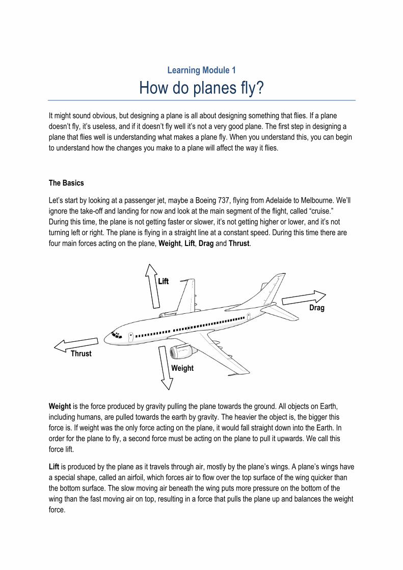
Let’s start by looking at a passenger jet, maybe a Boeing 737, flying from Adelaide to Melbourne. We’ll
ignore the take-off and landing for now and look at the main segment of the flight, called “cruise.”
During this time, the plane is not getting faster or slower, it’s not getting higher or lower, and it’s not
turning left or right. The plane is flying in a straight line at a constant speed. During this time there are
four main forces acting on the plane, Weight, Lift, Drag and Thrust.
Weight is the force produced by gravity pulling the plane towards the ground. All objects on Earth,
including humans, are pulled towards the earth by gravity. The heavier the object is, the bigger this
force is. If weight was the only force acting on the plane, it would fall straight down into the Earth. In
order for the plane to fly, a second force must be acting on the plane to pull it upwards. We call this
force lift.
Lift is produced by the plane as it travels through air, mostly by the plane’s wings. A plane’s wings have
a special shape, called an airfoil, which forces air to flow over the top surface of the wing quicker than
the bottom surface. The slow moving air beneath the wing puts more pressure on the bottom of the
wing than the fast moving air on top, resulting in a force that pulls the plane up and balances the weight
force.
Lift
Thrust
Drag
Weight
Lift
Drag is also produced by the plane travelling through air. When objects move through fluids, like air
and water, the fluid produces a force that opposes their motion. For instance, when you push a ball
floating in water it will travel in the direction you push it, but it will slow down and eventually stop. This is
because the water creates a force that pushes against the motion of the ball. Air acts the same way, so
to keep a plane moving forwards at a constant speed, another force is needed to overcome drag.
Thrust is the force produced by the plane’s engines. This force pulls the plane forward through the air
and overcomes the drag force produced by the air. Planes can have a variety of engines to produce
thrust, but the engines usually produce thrust by turning a propeller or accelerating a stream of air.
Propellers have a number of blades that rotate and create forces to pull the plane through the air. Each
blade has an airfoil cross-section, like a wing, and generates a lift force. Jet engines often have fans
that act like propellers, but they also accelerate a narrow stream of air. The air moves much faster than
the plane, but it has a lower mass. The momentum added to the stream of air is balanced by
momentum added to the plane, which provides the thrust force.
Together, these four forces determine where the plane goes. For example, if the thrust force is greater
than drag, the plane will accelerate. If the lift force is greater than weight, the plane will climb higher. It
should be noted that the descriptions of the forces given here is very simplified. More detail will be
added as necessary throughout later learning modules, and curious students can research this further
using the resources listed in recommended reading.
Plane components
Planes have a number of different components to help them fly. As we already mentioned, the wing is
responsible for generating lift. The main central body of the plane is called the fuselage. This houses
the cockpit, where the pilot sits. It may also contain a cabin for passengers, or a cargo bay for carrying
other items. At the rear of the fuselage are the horizontal and vertical tails (or stabilisers). These help
the plane to fly smoothly and stay heading in one direction. One or more engines provide thrust. These
engines may turn a propeller. Engines are usually located at the front of the fuselage, or below the
wings if there are a number of them, but they can also be located at the rear of the fuselage, above the
wing or in the wing. Planes also have landing gear to allow them to move on the ground, and a number
of controls (Aileron, Rudder etc) that will be discussed in Learning Module 2.
Key idea:
Weight pulls a plane downwards.
Lift pulls a plane upwards.
Drag pulls a plane backwards.
Thrust pulls a plane forwards.
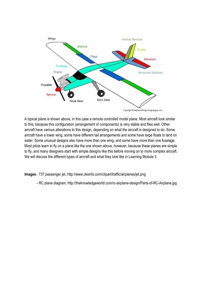
A typical plane is shown above, in this case a remote controlled model plane. Most aircraft look similar
to this, because this configuration (arrangement of components) is very stable and flies well. Other
aircraft have various alterations to this design, depending on what the aircraft is designed to do. Some
aircraft have a lower wing, some have different tail arrangements and some have large floats to land on
water. Some unusual designs also have more than one wing, and some have more than one fuselage.
Most pilots learn to fly on a plane like the one shown above, however, because these planes are simple
to fly, and many designers start with simple designs like this before moving on to more complex aircraft.
We will discuss the different types of aircraft and what they look like in Learning Module 3.
Images - 737 passenger jet, http://www.cksinfo.com/clipart/traffic/airplanes/jet.png
- RC plane diagram, http://theknowledgeworld.com/rc-airplane-design/Parts-of-RC-Airplane.jpg
Learning Module 2
How do pilots control planes?
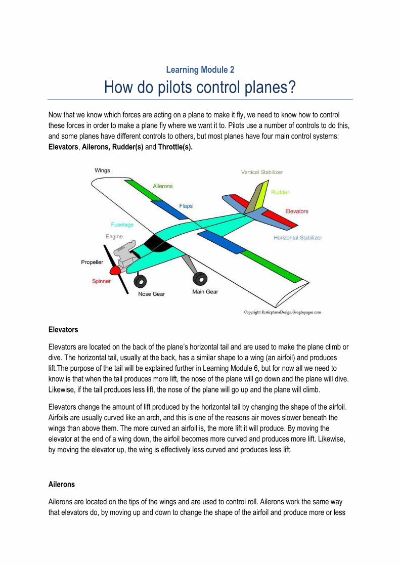
Now that we know which forces are acting on a plane to make it fly, we need to know how to control
these forces in order to make a plane fly where we want it to. Pilots use a number of controls to do this,
and some planes have different controls to others, but most planes have four main control systems:
Elevators, Ailerons, Rudder(s) and Throttle(s).
Elevators
Elevators are located on the back of the plane’s horizontal tail and are used to make the plane climb or
dive. The horizontal tail, usually at the back, has a similar shape to a wing (an airfoil) and produces
lift.The purpose of the tail will be explained further in Learning Module 6, but for now all we need to
know is that when the tail produces more lift, the nose of the plane will go down and the plane will dive.
Likewise, if the tail produces less lift, the nose of the plane will go up and the plane will climb.
Elevators change the amount of lift produced by the horizontal tail by changing the shape of the airfoil.
Airfoils are usually curved like an arch, and this is one of the reasons air moves slower beneath the
wings than above them. The more curved an airfoil is, the more lift it will produce. By moving the
elevator at the end of a wing down, the airfoil becomes more curved and produces more lift. Likewise,
by moving the elevator up, the wing is effectively less curved and produces less lift.
Ailerons
Ailerons are located on the tips of the wings and are used to control roll. Ailerons work the same way
that elevators do, by moving up and down to change the shape of the airfoil and produce more or less
lift. By moving one aileron up and the other down, one wing will generate less lift than the other. The
wing that generates less lift will drop, and the one that generates more will rise, and this will cause the
plane to roll.
When a plane rolls, the lift produced by the wings is no longer acting straight upwards, but is now acting
upwards and towards the lower of the two wings. Because of this, the plane will now turn towards the
low wing. Because of this, ailerons can be used to steer planes left or right.
Rudder(s)
A rudder is located on the plane’s vertical tail and is used to steer the plane left or right. Some aircraft
have more than one vertical tail, like the FA-18 fighter jet, and each tail has its own rudder. The vertical
tail on a plane is also an airfoil shape, but the airfoil is not curved. As a result, the vertical tail does not
normally generate lift. When the rudder is moved in one direction, the vertical tail is effectively curved,
and produces lift. However, this lift does not act vertically, as the vertical tail is not horizontal like the
wing. Lift always acts perpendicular to the wing or tail that generates it, so the lift generated by the
vertical tail will act horizontally. This lift will cause the plane to rotate left or right. If the rudder is moved
to the left, it will generate lift to the right, which will move the nose of the plane to the left. Rudders are
often slower at turning an aircraft than the ailerons, but they can turn the aircraft without rolling it and
are useful for small adjustments during takeoff, landing and other flights. Sometimes a pilot uses both
the rudder and the ailerons together while turning in order to produce a smoother flight.
Throttle(s)
A throttle controls the thrust produced by an engine and is used to make the plane go faster or slower.
Planes with more than one engine, like passenger jets, will have one throttle for each engine. The way
that the throttle works depends on the type of engine, but it will generally increase the amount of fuel
being consumed by the engine, which will in turn generate more heat or spin a propeller faster.
Depending on the position of the engines, increasing the throttle may also cause the plane to climb, roll
or turn. In fact, computer programs have been written that allow planes with two or more engines to be
flown and landed using only the throttles! These programs are to help aircraft to land safely when the
other controls have failed, and are not used very often.
Key idea:
Elevators are used to make a plane climb or dive.
Ailerons are used to make a plane roll left or right.
Rudders are used to make a plane turn left or right.
Throttles are used to make a plane go faster or slower.
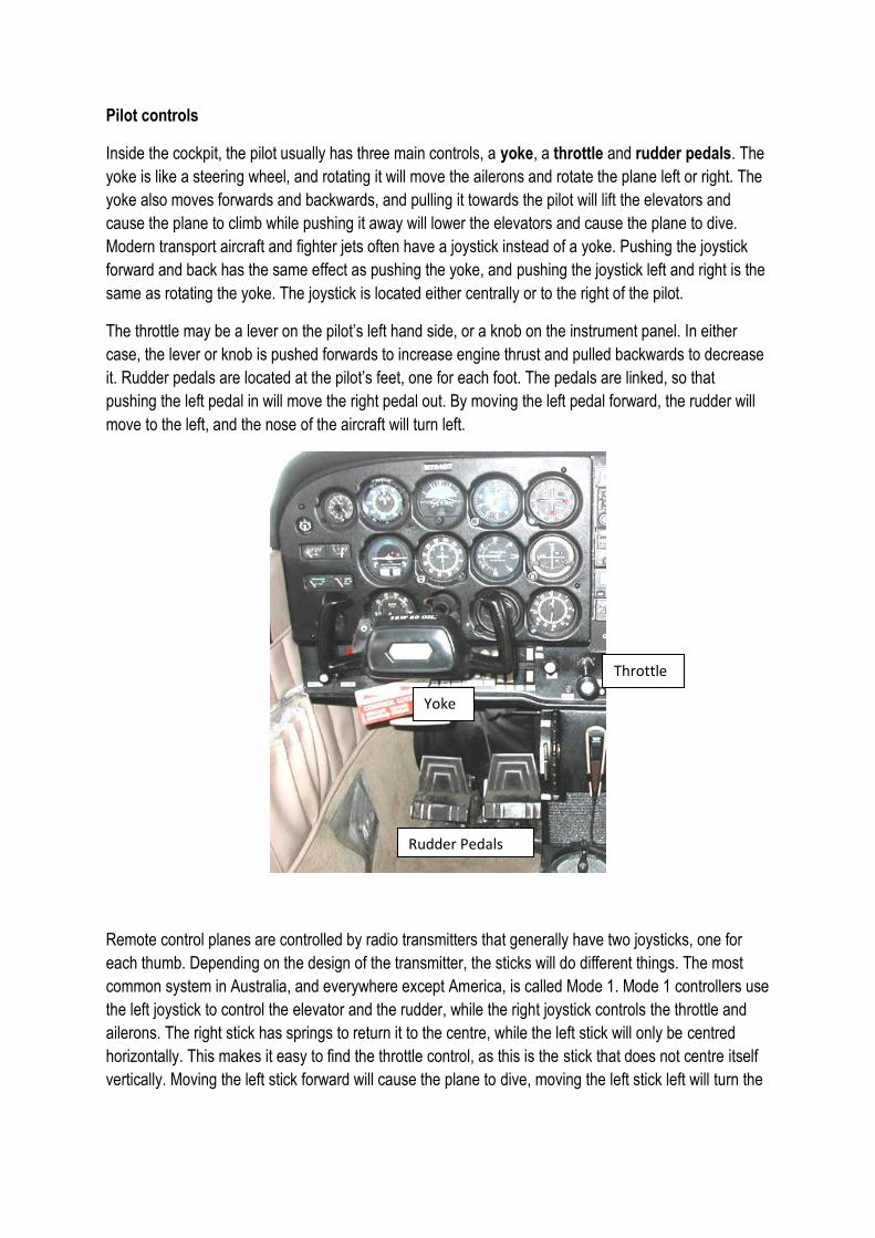
Pilot controls
Inside the cockpit, the pilot usually has three main controls, a yoke, a throttle and rudder pedals. The
yoke is like a steering wheel, and rotating it will move the ailerons and rotate the plane left or right. The
yoke also moves forwards and backwards, and pulling it towards the pilot will lift the elevators and
cause the plane to climb while pushing it away will lower the elevators and cause the plane to dive.
Modern transport aircraft and fighter jets often have a joystick instead of a yoke. Pushing the joystick
forward and back has the same effect as pushing the yoke, and pushing the joystick left and right is the
same as rotating the yoke. The joystick is located either centrally or to the right of the pilot.
The throttle may be a lever on the pilot’s left hand side, or a knob on the instrument panel. In either
case, the lever or knob is pushed forwards to increase engine thrust and pulled backwards to decrease
it. Rudder pedals are located at the pilot’s feet, one for each foot. The pedals are linked, so that
pushing the left pedal in will move the right pedal out. By moving the left pedal forward, the rudder will
move to the left, and the nose of the aircraft will turn left.
Remote control planes are controlled by radio transmitters that generally have two joysticks, one for
each thumb. Depending on the design of the transmitter, the sticks will do different things. The most
common system in Australia, and everywhere except America, is called Mode 1. Mode 1 controllers use
the left joystick to control the elevator and the rudder, while the right joystick controls the throttle and
ailerons. The right stick has springs to return it to the centre, while the left stick will only be centred
horizontally. This makes it easy to find the throttle control, as this is the stick that does not centre itself
vertically. Moving the left stick forward will cause the plane to dive, moving the left stick left will turn the
Yoke
Rudder Pedals
Throttle
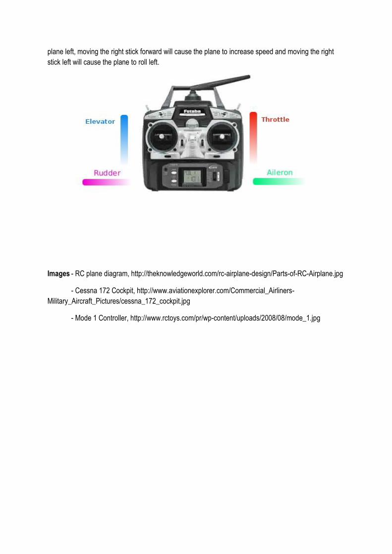
plane left, moving the right stick forward will cause the plane to increase speed and moving the right
stick left will cause the plane to roll left.
Images - RC plane diagram, http://theknowledgeworld.com/rc-airplane-design/Parts-of-RC-Airplane.jpg
- Cessna 172 Cockpit, http://www.aviationexplorer.com/Commercial_Airliners-
Military_Aircraft_Pictures/cessna_172_cockpit.jpg
- Mode 1 Controller, http://www.rctoys.com/pr/wp-content/uploads/2008/08/mode_1.jpg
Advanced concept:
Unusual control systems
While most aircraft use the four control systems explained here, sometimes
designers will use unusual systems in their planes. This might be because the
new system is more efficient, or more practical, or the designer might want to
design an aircraft that looks unusual. Here are some of the other systems that
have been used in aircraft.
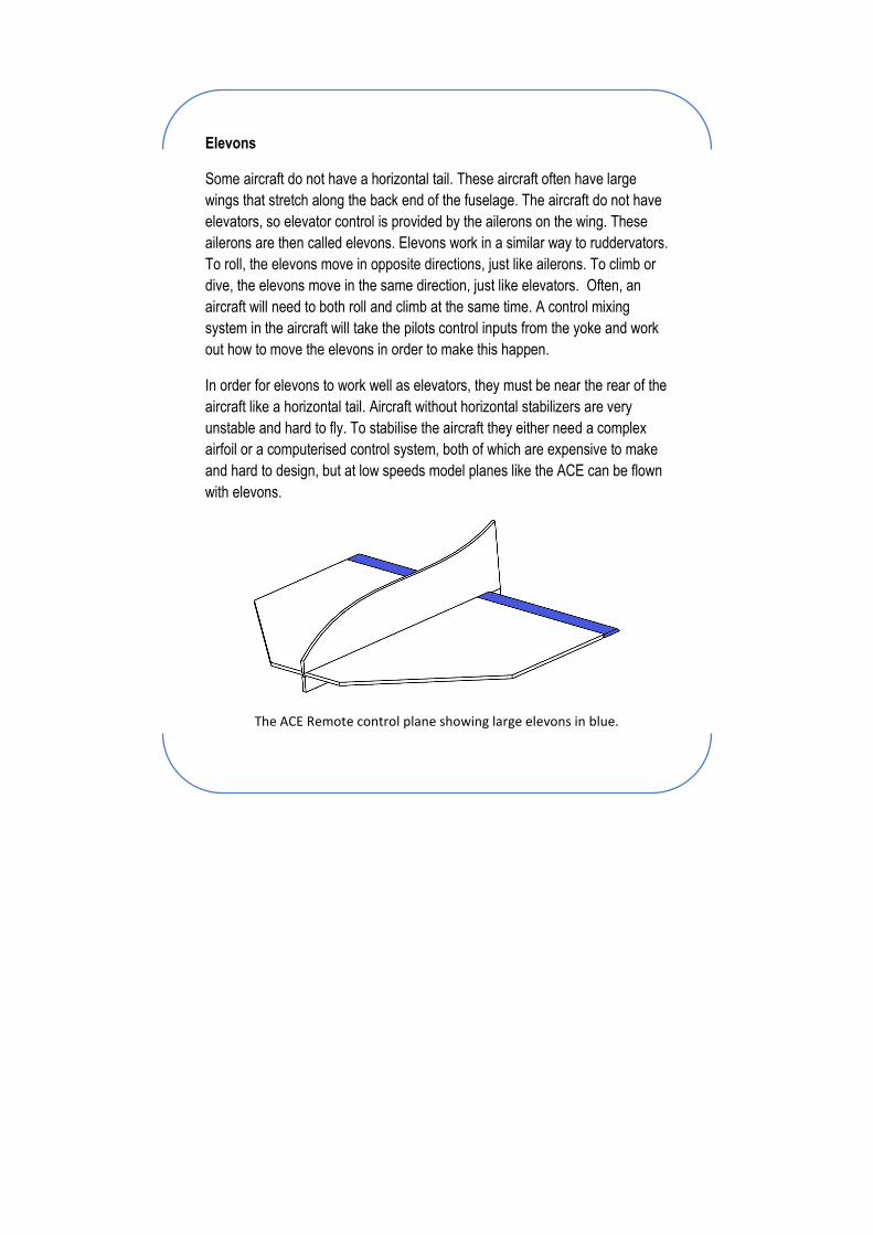
V tails
Normal aircraft have two horizontal stabilisers and a vertical stabiliser, giving a
total of 3 tails. V tails have two stabilisers that are angled like a V when viewed
from behind. Each of these has a moveable surface at the back, like an
elevator or rudder, and these surfaces are called ruddervators. Moving both
downwards has the same effect as moving elevators down, while moving the
left one down and the right one up turns the aircraft left. A complex control
mixing system is needed to translate a pilot’s input into ruddervator
movements.
V tails were designed to reduce drag. The idea is that having only 2 tails
instead of 3 would cause less drag, because each tail contributes drag. Having
less drag is beneficial for an aircraft as it can fly faster or further. In practice,
using only 2 tails requires you to make the tails bigger than each of the three
tails would have been, and this increases drag. This means that overall there is
little difference in drag. V tails can be useful for other reasons. For example,
the business jet below has an engine near the tail. A normal vertical tail would
be directly in the exhaust of the jet engine, which would damage the tail and
reduce engine thrust, and the V tail design avoids this problem.
A V tailed business jet
(image from http://waynefarley.com/aviation/wp-
content/uploads/2010/05/vision-sf50-1.jpg)
Elevons
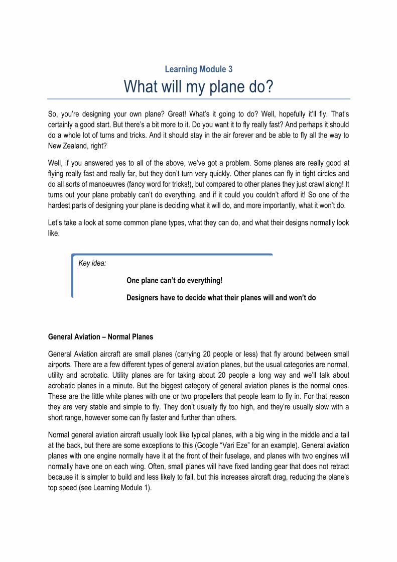
Some aircraft do not have a horizontal tail. These aircraft often have large
wings that stretch along the back end of the fuselage. The aircraft do not have
elevators, so elevator control is provided by the ailerons on the wing. These
ailerons are then called elevons. Elevons work in a similar way to ruddervators.
To roll, the elevons move in opposite directions, just like ailerons. To climb or
dive, the elevons move in the same direction, just like elevators. Often, an
aircraft will need to both roll and climb at the same time. A control mixing
system in the aircraft will take the pilots control inputs from the yoke and work
out how to move the elevons in order to make this happen.
In order for elevons to work well as elevators, they must be near the rear of the
aircraft like a horizontal tail. Aircraft without horizontal stabilizers are very
unstable and hard to fly. To stabilise the aircraft they either need a complex
airfoil or a computerised control system, both of which are expensive to make
and hard to design, but at low speeds model planes like the ACE can be flown
with elevons.
The ACE Remote control plane showing large elevons in blue.
Learning Module 3
What will my plane do?
So, you’re designing your own plane? Great! What’s it going to do? Well, hopefully it’ll fly. That’s
certainly a good start. But there’s a bit more to it. Do you want it to fly really fast? And perhaps it should
do a whole lot of turns and tricks. And it should stay in the air forever and be able to fly all the way to
New Zealand, right?
Well, if you answered yes to all of the above, we’ve got a problem. Some planes are really good at
flying really fast and really far, but they don’t turn very quickly. Other planes can fly in tight circles and
do all sorts of manoeuvres (fancy word for tricks!), but compared to other planes they just crawl along! It
turns out your plane probably can’t do everything, and if it could you couldn’t afford it! So one of the
hardest parts of designing your plane is deciding what it will do, and more importantly, what it won’t do.
Let’s take a look at some common plane types, what they can do, and what their designs normally look
like.
General Aviation – Normal Planes
General Aviation aircraft are small planes (carrying 20 people or less) that fly around between small
airports. There are a few different types of general aviation planes, but the usual categories are normal,
utility and acrobatic. Utility planes are for taking about 20 people a long way and we’ll talk about
acrobatic planes in a minute. But the biggest category of general aviation planes is the normal ones.
These are the little white planes with one or two propellers that people learn to fly in. For that reason
they are very stable and simple to fly. They don’t usually fly too high, and they’re usually slow with a
short range, however some can fly faster and further than others.
Normal general aviation aircraft usually look like typical planes, with a big wing in the middle and a tail
at the back, but there are some exceptions to this (Google “Vari Eze” for an example). General aviation
planes with one engine normally have it at the front of their fuselage, and planes with two engines will
normally have one on each wing. Often, small planes will have fixed landing gear that does not retract
because it is simpler to build and less likely to fail, but this increases aircraft drag, reducing the plane’s
top speed (see Learning Module 1).
Key idea:
One plane can’t do everything!
Designers have to decide what their planes will and won’t do
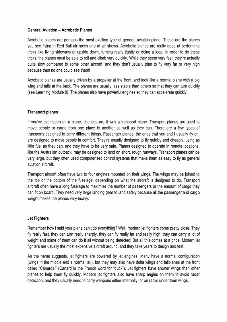
General Aviation – Acrobatic Planes
Acrobatic planes are perhaps the most exciting type of general aviation plane. These are the planes
you see flying in Red Bull air races and at air shows. Acrobatic planes are really good at performing
tricks like flying sideways or upside down, turning really tightly or doing a loop. In order to do these
tricks, the planes must be able to roll and climb very quickly. While they seem very fast, they’re actually
quite slow compared to some other aircraft, and they don’t usually plan to fly very far or very high
because then no one could see them!
Acrobatic planes are usually driven by a propeller at the front, and look like a normal plane with a big
wing and tails at the back. The planes are usually less stable than others so that they can turn quickly
(see Learning Module 8). The planes also have powerful engines so they can accelerate quickly.
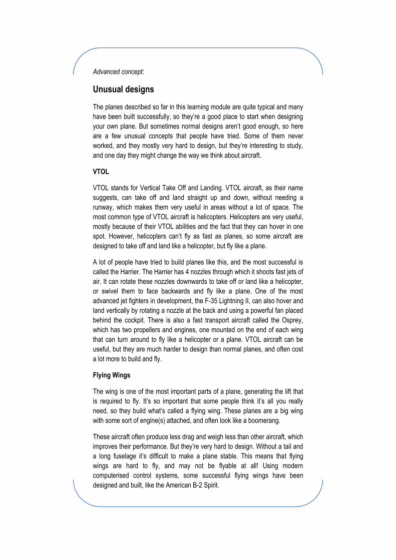
Transport planes
If you’ve ever been on a plane, chances are it was a transport plane. Transport planes are used to
move people or cargo from one place to another as well as they can. There are a few types of
transports designed to carry different things. Passenger planes, the ones that you and I usually fly on,
are designed to move people in comfort. They’re usually designed to fly quickly and cheaply, using as
little fuel as they can, and they have to be very safe. Planes designed to operate in remote locations,
like the Australian outback, may be designed to land on short, rough runways. Transport planes can be
very large, but they often used computerised control systems that make them as easy to fly as general
aviation aircraft.
Transport aircraft often have two to four engines mounted on their wings. The wings may be joined to
the top or the bottom of the fuselage, depending on what the aircraft is designed to do. Transport
aircraft often have a long fuselage to maximise the number of passengers or the amount of cargo they
can fit on board. They need very large landing gear to land safely because all the passenger and cargo
weight makes the planes very heavy.
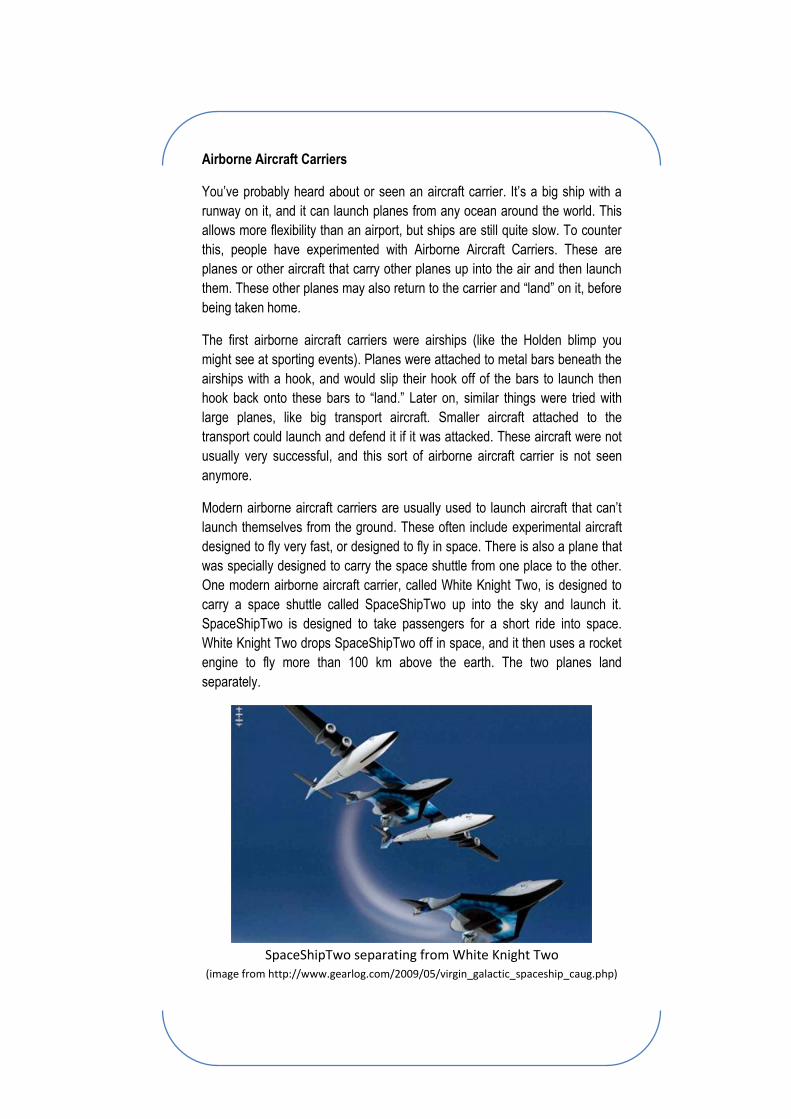
Jet Fighters
Remember how I said your plane can’t do everything? Well, modern jet fighters come pretty close. They
fly really fast, they can turn really sharply, they can fly really far and really high, they can carry a lot of
weight and some of them can do it all without being detected! But all this comes at a price. Modern jet
fighters are usually the most expensive aircraft around, and they take years to design and test.
As the name suggests, jet fighters are powered by jet engines. Many have a normal configuration
(wings in the middle and a normal tail), but they may also have delta wings and tailplanes at the front
called “Canards.” (Canard is the French word for “duck”). Jet fighters have shorter wings than other
planes to help them fly quickly. Modern jet fighters also have sharp angles on them to avoid radar
detection, and they usually need to carry weapons either internally, or on racks under their wings.
Your Plane
So now it’s time to design your own plane. One of the best ways to get started is to look at other planes
that you like, work out what you like about them and put all the best bits together in one plane. So
perhaps you want to make a jet fighter. You might like the wing from one, and the nose and cockpit
from another, and the tails of another. So you’ll draw them up, move them around and change them till
you’re happy!
But what happens when you change things? Will it get faster? Will it turn slower? During the next few
learning modules, we’ll look at the results you’d expect from a few common changes, like making the
wings bigger or putting in a bigger engine. But sometimes there’s not enough information around to
know what those changes will do, maybe because very few people have tried it! In that case, you just
have to make a good guess, then go out there and try it! Then, when someone else wants to do what
you did, you can tell them whether or not it works!
Images
1. Normal General Aviation Aircraft
(http://www.clker.com/cliparts/e/1/1/2/1246701343509158781C_172_line_drawing_oblique.svg.hi.png)
2. Acrobatic General Aviation Aircraft
(http://upload.wikimedia.org/wikipedia/commons/f/f6/Extra_300S_-_Peter_Besenyei.jpg)
3. Transport Aircraft
(http://www.cksinfo.com/clipart/traffic/airplanes/jet.png)
4. Jet Fighter (http://3.bp.blogspot.com/_XuJIbx1rx7Y/SIP9IJqZN7I/AAAAAAAAAso/6VZAnQBlB0g/s1600-
h/OSI_fighter_plane_01.jpg)
1 2
3
4
Advanced concept:
Unusual designs
The planes described so far in this learning module are quite typical and many
have been built successfully, so they’re a good place to start when designing
your own plane. But sometimes normal designs aren’t good enough, so here
are a few unusual concepts that people have tried. Some of them never
worked, and they mostly very hard to design, but they’re interesting to study,
and one day they might change the way we think about aircraft.
VTOL
VTOL stands for Vertical Take Off and Landing. VTOL aircraft, as their name
suggests, can take off and land straight up and down, without needing a
runway, which makes them very useful in areas without a lot of space. The
most common type of VTOL aircraft is helicopters. Helicopters are very useful,
mostly because of their VTOL abilities and the fact that they can hover in one
spot. However, helicopters can’t fly as fast as planes, so some aircraft are
designed to take off and land like a helicopter, but fly like a plane.
A lot of people have tried to build planes like this, and the most successful is
called the Harrier. The Harrier has 4 nozzles through which it shoots fast jets of
air. It can rotate these nozzles downwards to take off or land like a helicopter,
or swivel them to face backwards and fly like a plane. One of the most
advanced jet fighters in development, the F-35 Lightning II, can also hover and
land vertically by rotating a nozzle at the back and using a powerful fan placed
behind the cockpit. There is also a fast transport aircraft called the Osprey,
which has two propellers and engines, one mounted on the end of each wing
that can turn around to fly like a helicopter or a plane. VTOL aircraft can be
useful, but they are much harder to design than normal planes, and often cost
a lot more to build and fly.
Flying Wings
The wing is one of the most important parts of a plane, generating the lift that
is required to fly. It’s so important that some people think it’s all you really
need, so they build what’s called a flying wing. These planes are a big wing
with some sort of engine(s) attached, and often look like a boomerang.
These aircraft often produce less drag and weigh less than other aircraft, which
improves their performance. But they’re very hard to design. Without a tail and
a long fuselage it’s difficult to make a plane stable. This means that flying
wings are hard to fly, and may not be flyable at all! Using modern
computerised control systems, some successful flying wings have been
designed and built, like the American B-2 Spirit.
Airborne Aircraft Carriers
You’ve probably heard about or seen an aircraft carrier. It’s a big ship with a
runway on it, and it can launch planes from any ocean around the world. This
allows more flexibility than an airport, but ships are still quite slow. To counter
this, people have experimented with Airborne Aircraft Carriers. These are
planes or other aircraft that carry other planes up into the air and then launch
them. These other planes may also return to the carrier and “land” on it, before
being taken home.
The first airborne aircraft carriers were airships (like the Holden blimp you
might see at sporting events). Planes were attached to metal bars beneath the
airships with a hook, and would slip their hook off of the bars to launch then
hook back onto these bars to “land.” Later on, similar things were tried with
large planes, like big transport aircraft. Smaller aircraft attached to the
transport could launch and defend it if it was attacked. These aircraft were not
usually very successful, and this sort of airborne aircraft carrier is not seen
anymore.
Modern airborne aircraft carriers are usually used to launch aircraft that can’t
launch themselves from the ground. These often include experimental aircraft
designed to fly very fast, or designed to fly in space. There is also a plane that
was specially designed to carry the space shuttle from one place to the other.
One modern airborne aircraft carrier, called White Knight Two, is designed to
carry a space shuttle called SpaceShipTwo up into the sky and launch it.
SpaceShipTwo is designed to take passengers for a short ride into space.
White Knight Two drops SpaceShipTwo off in space, and it then uses a rocket
engine to fly more than 100 km above the earth. The two planes land
separately.
SpaceShipTwo separating from White Knight Two
(image from http://www.gearlog.com/2009/05/virgin_galactic_spaceship_caug.php)
Learning Module 4
How big should my wing be?
The main purpose of a wing is to produce lift for an aircraft. Lift is the force that keeps the aircraft in the
air (see Learning Module 1). Changing the size of the wing can change the amount of lift generated by
the aircraft, which can affect aircraft performance.
Size
The most important part of wing size is the area of the wing when looking at it from below. This area is
called the planform area. The planform area, which sometimes includes the bottom of the fuselage, is
an indication of the area over which lift is generated. If you have a greater planform area, there is a
larger area over which lift is generated, so more lift is generated.
Performance
So if we can get more lift by having a bigger wing, why don’t we just have the biggest wing possible?
More lift can be a good thing. It can allow the aircraft to be heavier, increasing the weight that it can
carry or the distance it can fly. But the increase in lift comes at the cost of increased weight and drag.
A lot of the time, when an aircraft is flying, it will be in cruise. Cruise is where the aircraft is moving
forwards without changing speed or altitude. When an aircraft is cruising, the lift force it produces must
be equal to its weight. If it is lower, the aircraft will fall out of the sky. If it is higher, the aircraft will be
climbing. This means that if we have more lift, we can have a heavier aircraft. This allows the aircraft to
carry more passengers or cargo, meaning the person flying it can make more money. It may also
increase the amount of fuel the aircraft can take, which increases its range, which is the distance that it
can fly.
Larger wings also increase drag, which will increase the required power, or thrust, to move the aircraft
forward. This means bigger engines and more fuel will need to be carried. Also, large wings are often
longer than small wings. Long wings bend a lot more, and the wings need to be made stronger. The
additional strength required means the wing will be heavier. So while the plane has more lift, it also
requires more lift to carry the wings. If this is not designed well, then the extra weight of the wings may
be greater than the extra lift, and the plane’s cargo weight may be reduced.
Key idea:
Increasing planform area increases lift
Advanced concept:
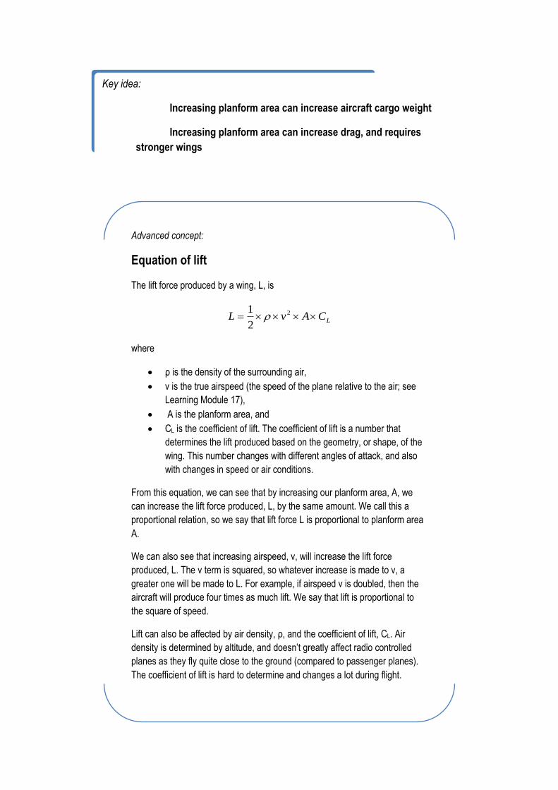
Equation of lift
The lift force produced by a wing, L, is
LCAvL 2
2
1
where
ρ is the density of the surrounding air,
v is the true airspeed (the speed of the plane relative to the air; see
Learning Module 17),
A is the planform area, and
CL is the coefficient of lift. The coefficient of lift is a number that
determines the lift produced based on the geometry, or shape, of the
wing. This number changes with different angles of attack, and also
with changes in speed or air conditions.
From this equation, we can see that by increasing our planform area, A, we
can increase the lift force produced, L, by the same amount. We call this a
proportional relation, so we say that lift force L is proportional to planform area
A.
We can also see that increasing airspeed, v, will increase the lift force
produced, L. The v term is squared, so whatever increase is made to v, a
greater one will be made to L. For example, if airspeed v is doubled, then the
aircraft will produce four times as much lift. We say that lift is proportional to
the square of speed.
Lift can also be affected by air density, ρ, and the coefficient of lift, CL. Air
density is determined by altitude, and doesn’t greatly affect radio controlled
planes as they fly quite close to the ground (compared to passenger planes).
The coefficient of lift is hard to determine and changes a lot during flight.
Key idea:
Increasing planform area can increase aircraft cargo weight
Increasing planform area can increase drag, and requires
stronger wings
Learning Module 5
What shape should my wing be?
There are a lot of things you can change about the shape of a wing. Some changes are obvious, while
some are more subtle, but each change affects the way that a plane flies. Since there are so many
changes, and some are quite complicated, we’ll focus on the simple ones that can easily be made in
your designs.
Number of Wings
Most modern planes have only one wing, but many of the first airplanes had two wings, or three, or
even more! There are some advantages to having more than one wing. Biplanes are planes which have
two wings, one on top of the other. Having two wings means that the wings don’t have to be as wide,
because the area of both wings contributes to lift. Shorter wings also allow biplanes to be more
manoeuvrable, which means they can roll and turn very quickly. The wings are also stronger than a
single wing, as they can support each other. The materials used to make early planes, often wood and
fabric, were not as strong as modern materials like aluminium, and this made the biplane configuration
very popular.
The biplane configuration has one main disadvantage. Biplanes have more drag from their two wings
than a one winged plane, or monoplane. This drag only gets worse as speeds increase, and biplanes
are limited to low speed flight. As time went on, people developed stronger materials, which allowed
them to make monoplanes more easily. Engine technology also improved and people wanted to fly
faster and faster, and biplanes fell out of favour in the 1930s-1940s.
When designing a model plane, especially a simple one made out of foam, structural considerations are
less important. Monoplanes are easier to make than biplanes because they do not require braces
connecting the two wings, and only one wing needs to be cut out. It is also easier to feed one wing
through the body of your aircraft than two, and mounting the second wing above the fuselage would be
complicated. For this reason I suggest you try a standard, one wing design.
Key idea:
One wing model planes are easier to build than biplanes
Vertical Position
Some planes have their wing above the fuselage, and some have it below. Others have it right in the
middle. The position of the wing is usually decided by what the plane is meant to do. For example,
passenger jets usually have low wings under the fuselage. This means the engines can be placed
under the wing and kept further from the passengers, reducing noise. Landing gear can be located on
the wings and will be closer to the ground, meaning they don’t have to be as long. The low wing also
improves the chances of passengers surviving a crash. For example, if the plane lands in a river, it will
float for a while at the level of the wing, with the passenger cabin above the water. On the other hand, a
plane that’s built to fly in the outback should have a high wing. This keeps wing mounted engines
higher above the ground, so that they don’t get damaged on bumpy, uneven runways. Planes designed
to land on water also have high wings so that the wing doesn’t touch the water, as this would increase
drag and might damage the wing. Fighter planes often have wings in the middle of the fuselage. This
helps them to manoeuvre better, as well as allowing them to see above and below the wing easily.
When building a simple model plane, the placement of the wing can be whatever the builder desires
without any problems. Usually model planes are made to look like existing planes, and they simply
mimic the real plane. Model planes made of foam are easiest to build with a wing somewhere in the
middle of the fuselage, due to the construction method used. This allows part of the fuselage to be
above the wing and part below, and the two can join around the wing for strength. The battery is often
attached to the fuselage just above or below the wing. It is good to have the battery in the centre of the
fuselage with regards to height or just below the centre, so a low wing with the battery on top is a good
solution.
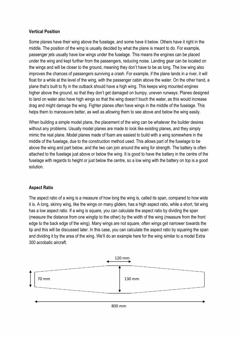
Aspect Ratio
The aspect ratio of a wing is a measure of how long the wing is, called its span, compared to how wide
it is. A long, skinny wing, like the wings on many gliders, has a high aspect ratio, while a short, fat wing
has a low aspect ratio. If a wing is square, you can calculate the aspect ratio by dividing the span
(measure the distance from one wingtip to the other) by the width of the wing (measure from the front
edge to the back edge of the wing). Many wings are not square, often wings get narrower towards the
tip and this will be discussed later. In this case, you can calculate the aspect ratio by squaring the span
and dividing it by the area of the wing. We’ll do an example here for the wing similar to a model Extra
300 acrobatic aircraft.
120 mm
800 mm
70 mm 130 mm
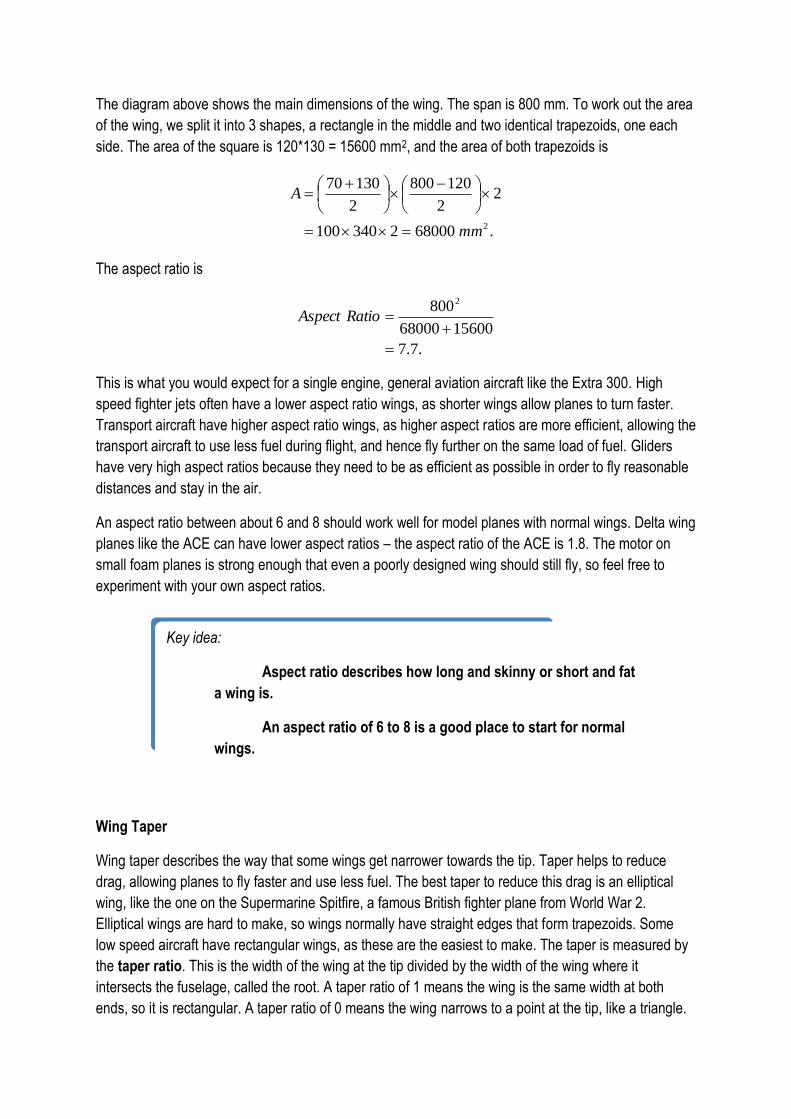
The diagram above shows the main dimensions of the wing. The span is 800 mm. To work out the area
of the wing, we split it into 3 shapes, a rectangle in the middle and two identical trapezoids, one each
side. The area of the square is 120*130 = 15600 mm2, and the area of both trapezoids is
.680002340100
22
120800
2
13070
2mm
A
The aspect ratio is
.7.7
1560068000
8002
RatioAspect
This is what you would expect for a single engine, general aviation aircraft like the Extra 300. High
speed fighter jets often have a lower aspect ratio wings, as shorter wings allow planes to turn faster.
Transport aircraft have higher aspect ratio wings, as higher aspect ratios are more efficient, allowing the
transport aircraft to use less fuel during flight, and hence fly further on the same load of fuel. Gliders
have very high aspect ratios because they need to be as efficient as possible in order to fly reasonable
distances and stay in the air.
An aspect ratio between about 6 and 8 should work well for model planes with normal wings. Delta wing
planes like the ACE can have lower aspect ratios – the aspect ratio of the ACE is 1.8. The motor on
small foam planes is strong enough that even a poorly designed wing should still fly, so feel free to
experiment with your own aspect ratios.
Wing Taper
Wing taper describes the way that some wings get narrower towards the tip. Taper helps to reduce
drag, allowing planes to fly faster and use less fuel. The best taper to reduce this drag is an elliptical
wing, like the one on the Supermarine Spitfire, a famous British fighter plane from World War 2.
Elliptical wings are hard to make, so wings normally have straight edges that form trapezoids. Some
low speed aircraft have rectangular wings, as these are the easiest to make. The taper is measured by
the taper ratio. This is the width of the wing at the tip divided by the width of the wing where it
intersects the fuselage, called the root. A taper ratio of 1 means the wing is the same width at both
ends, so it is rectangular. A taper ratio of 0 means the wing narrows to a point at the tip, like a triangle.
Key idea:
Aspect ratio describes how long and skinny or short and fat
a wing is.
An aspect ratio of 6 to 8 is a good place to start for normal
wings.
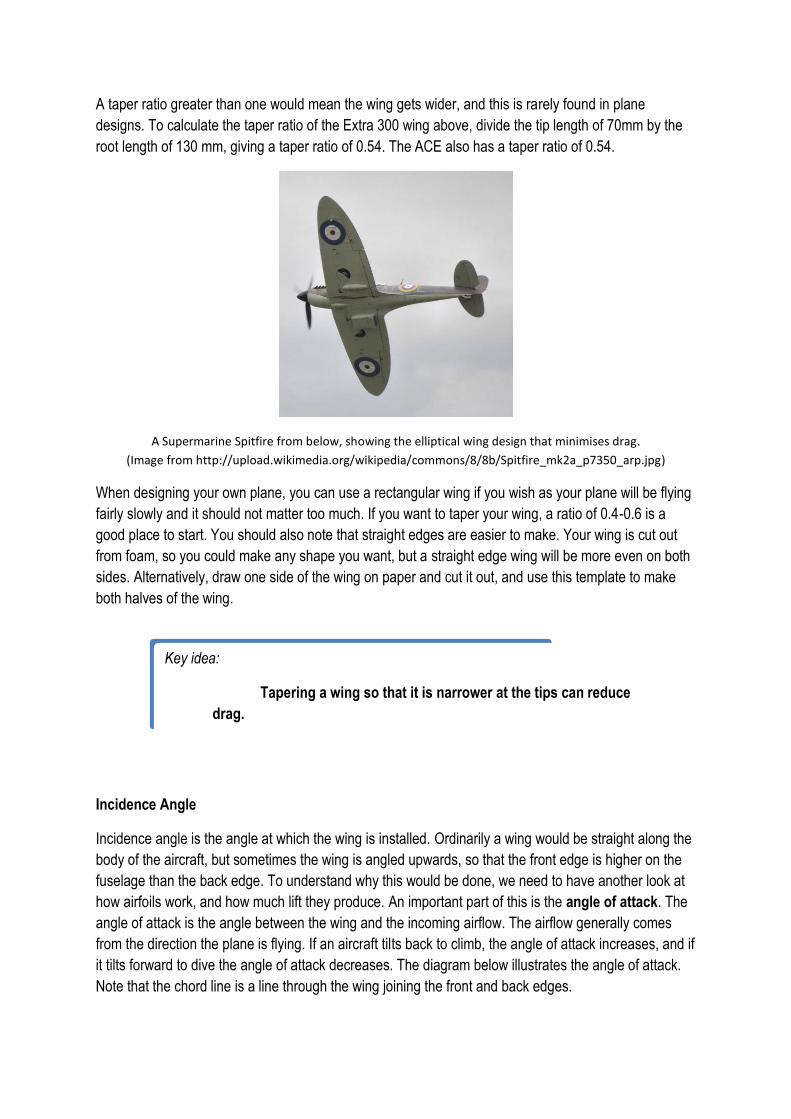
A taper ratio greater than one would mean the wing gets wider, and this is rarely found in plane
designs. To calculate the taper ratio of the Extra 300 wing above, divide the tip length of 70mm by the
root length of 130 mm, giving a taper ratio of 0.54. The ACE also has a taper ratio of 0.54.
A Supermarine Spitfire from below, showing the elliptical wing design that minimises drag.
(Image from http://upload.wikimedia.org/wikipedia/commons/8/8b/Spitfire_mk2a_p7350_arp.jpg)
When designing your own plane, you can use a rectangular wing if you wish as your plane will be flying
fairly slowly and it should not matter too much. If you want to taper your wing, a ratio of 0.4-0.6 is a
good place to start. You should also note that straight edges are easier to make. Your wing is cut out
from foam, so you could make any shape you want, but a straight edge wing will be more even on both
sides. Alternatively, draw one side of the wing on paper and cut it out, and use this template to make
both halves of the wing.
Incidence Angle
Incidence angle is the angle at which the wing is installed. Ordinarily a wing would be straight along the
body of the aircraft, but sometimes the wing is angled upwards, so that the front edge is higher on the
fuselage than the back edge. To understand why this would be done, we need to have another look at
how airfoils work, and how much lift they produce. An important part of this is the angle of attack. The
angle of attack is the angle between the wing and the incoming airflow. The airflow generally comes
from the direction the plane is flying. If an aircraft tilts back to climb, the angle of attack increases, and if
it tilts forward to dive the angle of attack decreases. The diagram below illustrates the angle of attack.
Note that the chord line is a line through the wing joining the front and back edges.
Key idea:
Tapering a wing so that it is narrower at the tips can reduce
drag.
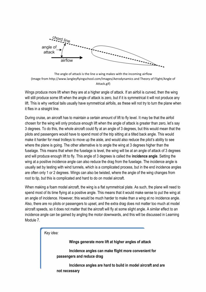
The angle of attack is the line a wing makes with the incoming airflow
(Image from http://www.langleyflyingschool.com/Images/Aerodynamics and Theory of Flight/Angle of
Attack.gif)
Wings produce more lift when they are at a higher angle of attack. If an airfoil is curved, then the wing
will still produce some lift when the angle of attack is zero, but if it is symmetrical it will not produce any
lift. This is why vertical tails usually have symmetrical airfoils, as these will not try to turn the plane when
it flies in a straight line.
During cruise, an aircraft has to maintain a certain amount of lift to fly level. It may be that the airfoil
chosen for the wing will only produce enough lift when the angle of attack is greater than zero, let’s say
3 degrees. To do this, the whole aircraft could fly at an angle of 3 degrees, but this would mean that the
pilots and passengers would have to spend most of the trip sitting at a tilted back angle. This would
make it harder for meal trolleys to move up the aisle, and would also reduce the pilot’s ability to see
where the plane is going. The other alternative is to angle the wing at 3 degrees higher than the
fuselage. This means that when the fuselage is level, the wing will be at an angle of attack of 3 degrees
and will produce enough lift to fly. This angle of 3 degrees is called the incidence angle. Setting the
wing at a positive incidence angle can also reduce the drag from the fuselage. The incidence angle is
usually set by testing with wind tunnels, which is a complicated process, but in the end incidence angles
are often only 1 or 2 degrees. Wings can also be twisted, where the angle of the wing changes from
root to tip, but this is complicated and hard to do on model aircraft.
When making a foam model aircraft, the wing is a flat symmetrical plate. As such, the plane will need to
spend most of its time flying at a positive angle. This means that it would make sense to put the wing at
an angle of incidence. However, this would be much harder to make than a wing at no incidence angle.
Also, there are no pilots or passengers to upset, and the extra drag does not matter too much at model
aircraft speeds, so it does not matter that the aircraft will fly at some slight angle. A similar effect to an
incidence angle can be gained by angling the motor downwards, and this will be discussed in Learning
Module 7.
Key idea:
Wings generate more lift at higher angles of attack
Incidence angles can make flight more convenient for
passengers and reduce drag
Incidence angles are hard to build in model aircraft and are
not necessary
Advanced concept:
Estimating the lift coefficient, CL
As we saw in Learning Module 4, the lift force produced by a wing, L, is
LCAvL 2
2
1
During cruise, the lift force is equal to the weight of the aircraft. If we know the
weight of the aircraft, and can measure or estimate the rest of the variables,
we can calculate the lift coefficient during cruise. We’ve already seen how to
find the planform area, A, but we need to make sure we convert it into square
metres. If it is measured in square millimetres, we need to divide it by
1000000.
The density of the air can be measured, but it is easier to use a standard
value. The standard atmosphere is a list of air pressures, temperatures and
densities at different altitudes (or heights) throughout the Earth atmosphere.
Since our planes fly quite low, we’ll use the sea level value of density, which is
1.225 kg/m3. This will be accurate on days that are about 15°C.
The weight is simple to measure using scales, but it must be used in Newtons,
a unit of force, not kilograms or grams. To convert kilograms into Newtons,
multiply the weight in kilograms by 9.81. To measure the speed, find two
objects that are a reasonable distance apart, like two trees near an oval.
Measure or guess the distance between them. Now fly your plane as level as
possible, without speeding up or climbing, past both objects and time how long
it takes. Then divide the distance (in metres) by the time taken (in seconds)
and you’ll get a rough idea of how fast you’re flying.
Once you have all these numbers, you have to reverse the above equation to
find the coefficient of lift. It should look as follows:
Av
LCL
2
2
Let’s try it with some estimates for the Extra 300 model we mentioned before.
The area of the wing, in square metres, is 0.0836 m2. Let’s guess that it weighs
about 350 grams, which equals 3.4 Newtons, and that it flies at about 10 m/s.
Finally, using our estimate of 1.225 kg/m3 for density, we get a value of CL =
0.66
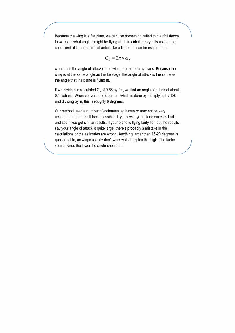
Because the wing is a flat plate, we can use something called thin airfoil theory
to work out what angle it might be flying at. Thin airfoil theory tells us that the
coefficient of lift for a thin flat airfoil, like a flat plate, can be estimated as
,2 LC
where α is the angle of attack of the wing, measured in radians. Because the
wing is at the same angle as the fuselage, the angle of attack is the same as
the angle that the plane is flying at.
If we divide our calculated CL of 0.66 by 2π, we find an angle of attack of about
0.1 radians. When converted to degrees, which is done by multiplying by 180
and dividing by π, this is roughly 6 degrees.
Our method used a number of estimates, so it may or may not be very
accurate, but the result looks possible. Try this with your plane once it’s built
and see if you get similar results. If your plane is flying fairly flat, but the results
say your angle of attack is quite large, there’s probably a mistake in the
calculations or the estimates are wrong. Anything larger than 15-20 degrees is
questionable, as wings usually don’t work well at angles this high. The faster
you’re flying, the lower the angle should be.
Learning Module 6
What should my tail look like?
The tail of a plane is a lot smaller than the wing, but it’s just as important. Tails provide stability,
allowing planes to fly smoothly and easily through the air. They also hold the elevators and rudders,
which are essential for controlling where the plane flies. And finally, they have a big impact on what
your plane looks like, so you want them to look cool! Here are a few hints on how to design a tail that
will keep your plane stable and controllable. I’ll leave the looking cool bit up to you.
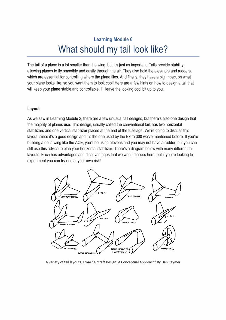
Layout
As we saw in Learning Module 2, there are a few unusual tail designs, but there’s also one design that
the majority of planes use. This design, usually called the conventional tail, has two horizontal
stabilizers and one vertical stabilizer placed at the end of the fuselage. We’re going to discuss this
layout, since it’s a good design and it’s the one used by the Extra 300 we’ve mentioned before. If you’re
building a delta wing like the ACE, you’ll be using elevons and you may not have a rudder, but you can
still use this advice to plan your horizontal stabilizer. There’s a diagram below with many different tail
layouts. Each has advantages and disadvantages that we won’t discuss here, but if you’re looking to
experiment you can try one at your own risk!
A variety of tail layouts. From “Aircraft Design: A Conceptual Approach” By Dan Raymer
Tail Placement
All the tails shown above are placed at the back end of the aircraft. There are some alternatives, such
as the delta wing without a horizontal tail that’s seen in the ACE, but these can be tricky to design and
fly. There are a few good reasons why tails are at the back end of the aircraft. Firstly, tails at the end of
the aircraft are good for stability. This is especially true of vertical stabilizers, as putting a vertical
stabilizer at the front of your plane will make it want to turn around and fly backwards! Think of a
weather vane or an arrow – the fins are always on the back. Putting a horizontal stabilizer on the front
of the plane, called a canard, is also unstable, but this can be balanced by the wing because the wing is
also horizontal. We’ll look at canards in the advanced concept later on.
Tails are usually located at the back of the plane, rather than partway through the fuselage, because
tails are more effective the further back they are. The airplane has a point called the centre of gravity,
which will be explained further in Learning Module 8. For now, all we need to know is that it’s usually in
the front half of the plane, and whenever the aircraft turns, whether it’s rolling, turning or climbing, it
turns around this point. If you think of your plane like a see saw, the centre of gravity is the pivot point
of the seesaw, which is the fixed point in the middle that the see saw rotates around. Now, when two
people play on a see saw and want to balance it, the heavier person sits closer to the pivot. This is
because the further away from the pivot you get, the greater effect you’ll have on the see saw.
Because tails are used to steer the whole aircraft, we want them to have the biggest effect possible. By
locating them at the back of the aircraft, they will be as far away as possible from the centre of gravity.
That way, when the elevator creates a lift force, it will have a large effect on the plane and it will rotate
quicker. It’s also worth noting that a small tail a long way back from the centre of gravity is equivalent to
a large tail close to the centre of gravity, but a small tail will generate less drag. We’ll discuss tail sizes
later.
The last thing to note is that the location of the tails can depend on the design of your fuselage. We
haven’t discussed fuselage design yet – largely this will be up to you and what you think looks cool.
Where you put your engine will determine a lot of your design, but you should also consider tail
placement. When the engine is at the front, like most propeller planes, the fuselage gets narrower
towards the back and ends in the tail. When the engine is at the back, the tail has to be located around
it. Modern jet fighters often have one or two engines that point out the back, and the tail has to be
located around them – the twin tail design is often used for this.
Key idea:
Vertical tails must be at the back of the plane.
Horizontal tails can be at the front, but it’s easier to put them
at the back.
The tail should be as far from the centre of gravity as
possible, which usually means the back of the plane.
Tail Shape
The shape of the tail is fairly similar to the wing. Aircraft tail design is a complex process, and often the
shape, size and position of the tail will change a few times during the design process. There are a few
guidelines to designing a tail shape that will get you started on the right track, and will be good enough
for most radio controlled model planes. In the end, while some tails will work better than others, most
tails will be flyable, so feel free to add your own artistic touch – this is the looking cool part I was talking
about earlier.
As a general rule, horizontal tails have a lower aspect ratio than the aircraft’s wing. This means they are
shorter and fatter. An aspect ratio between 3 and 5 is a good place to start. The taper ratio of the
horizontal tail can be similar to the wing, between 0.3 and 0.6 is a good place to start but feel free to
use more or less. Draw a tail that you like the look of, then check what its aspect ratio and taper ratio
are, and only change it if it’s a long way outside the ranges above. Vertical tails have even lower aspect
ratios, generally between 1 and 2 but they can be lower than 1, meaning the tail is longer than it is tall.
It can be hard to judge the aspect ratio of a tail, especially on the ACE where the tail is curved, so just
guess. As long as the tail’s not a lot longer than it is wide it should be ok. Guidelines for taper ratio are
the same as for the horizontal tail, between 0.3 and 0.6 is good.
The Extra 300 we mentioned earlier has a horizontal tail aspect ratio of 3.5, and a taper ratio of 0.8. The
taper ratio is quite high, and the tail could be narrower, but the plane flies well and that’s what matters
in the end. The vertical tail has an aspect ratio of 1.5 and a taper ratio of 0.3, perfectly within the
guidelines.
Tail Size
Tail size, like tail shape, is usually changed a number of times during the design of a plane. A tail that is
too big causes too much drag and slows the plane down. A tail that is too small will not be able to
stabilise a plane, and may not be strong enough to stop it from crashing. When designing a tail for your
model aircraft, it is safer to design a tail that might be too big. If it turns out your plane is too slow, you
can try to reduce the size, but if you make it too small it’s hard to fix, and could cause a spectacular
crash that’ll be even harder to fix! Professional aircraft designers use a fancy method that compares
their plane to similar planes and works out how big their tails should be. The maths involved is a little bit
complicated, but the idea is really simple and easy to do yourself.
Key idea:
Horizontal tails are usually shorter and fatter than wings.
Vertical tails are usually shorter and fatter than horizontal
tails.
First, find a number of other planes that are similar to yours. This will depend on what sort of plane
you’re making (remember Learning Module 3). If you’re trying to make a copy of an existing plane,
that’s the only one you really need to look at. Find pictures of these other planes, particularly from the
side for vertical tails and above or below for horizontal tails. You may have already used these pictures
to help make the wing and fuselage. Now compare the size of the tails to the wings. You can do this
roughly just by looking, or you might like to measure it. Once you’ve designed this, draw your tail and
compare it with the others. It doesn’t have to be the same, but it should be similar. We’ll see how to do
this with an example.
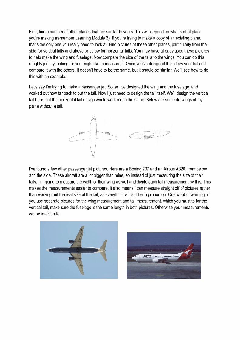
Let’s say I’m trying to make a passenger jet. So far I’ve designed the wing and the fuselage, and
worked out how far back to put the tail. Now I just need to design the tail itself. We’ll design the vertical
tail here, but the horizontal tail design would work much the same. Below are some drawings of my
plane without a tail.
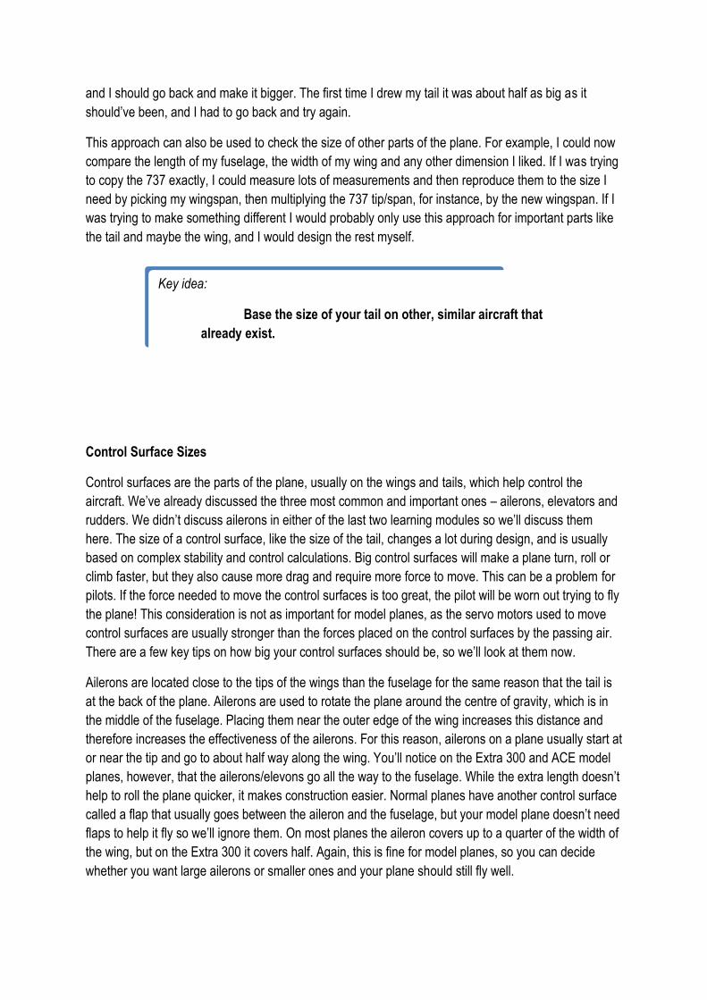
I’ve found a few other passenger jet pictures. Here are a Boeing 737 and an Airbus A320, from below
and the side. These aircraft are a lot bigger than mine, so instead of just measuring the size of their
tails, I’m going to measure the width of their wing as well and divide each tail measurement by this. This
makes the measurements easier to compare. It also means I can measure straight off of pictures rather
than working out the real size of the tail, as everything will still be in proportion. One word of warning, if
you use separate pictures for the wing measurement and tail measurement, which you must to for the
vertical tail, make sure the fuselage is the same length in both pictures. Otherwise your measurements
will be inaccurate.

I’ve measured the span of the wing, the height of the vertical tail, the length of the tip and the length of
the root for each of the two planes. I’ve then divided the last 3 measurements by the span of the wing.
The measurements are in mm, but because I’m dividing two measurements, the units don’t matter as
long as they’re the same. The results are in the table below. As you can see, the numbers are quite
similar. This is not surprising since the planes look similar.
Plane Span Height Tip Root Height/Span Tip/Span Root/Span
737 70 15 5 15 0.21 0.071 0.21
A320 72 14 4 15 0.19 0.056 0.21
Now it’s time to design my tail. I want mine to be a bit squarer, with the tip a bit longer because my
plane is designed to fly slower. It also won’t tilt backwards as much. I’ve drawn my tail, as you can see
below, and done the same measurements.
Plane Span Height Tip Root Height/Span Tip/Span Root/Span
Mine 130 26 14 25 0.20 0.108 0.19
You might notice that my measurements are bigger than the other two planes, but once divided by span
they are roughly the same. The last 3 numbers are the ones we need to compare. The height of my tail,
divided by span, is very similar to the two examples. The tip is longer, and the root is a bit smaller, but
the numbers are close. If my tip/span had been something like 0.010, it would probably be too small
and I should go back and make it bigger. The first time I drew my tail it was about half as big as it
should’ve been, and I had to go back and try again.
This approach can also be used to check the size of other parts of the plane. For example, I could now
compare the length of my fuselage, the width of my wing and any other dimension I liked. If I was trying
to copy the 737 exactly, I could measure lots of measurements and then reproduce them to the size I
need by picking my wingspan, then multiplying the 737 tip/span, for instance, by the new wingspan. If I
was trying to make something different I would probably only use this approach for important parts like
the tail and maybe the wing, and I would design the rest myself.
Control Surface Sizes
Control surfaces are the parts of the plane, usually on the wings and tails, which help control the
aircraft. We’ve already discussed the three most common and important ones – ailerons, elevators and
rudders. We didn’t discuss ailerons in either of the last two learning modules so we’ll discuss them
here. The size of a control surface, like the size of the tail, changes a lot during design, and is usually
based on complex stability and control calculations. Big control surfaces will make a plane turn, roll or
climb faster, but they also cause more drag and require more force to move. This can be a problem for
pilots. If the force needed to move the control surfaces is too great, the pilot will be worn out trying to fly
the plane! This consideration is not as important for model planes, as the servo motors used to move
control surfaces are usually stronger than the forces placed on the control surfaces by the passing air.
There are a few key tips on how big your control surfaces should be, so we’ll look at them now.
Ailerons are located close to the tips of the wings than the fuselage for the same reason that the tail is
at the back of the plane. Ailerons are used to rotate the plane around the centre of gravity, which is in
the middle of the fuselage. Placing them near the outer edge of the wing increases this distance and
therefore increases the effectiveness of the ailerons. For this reason, ailerons on a plane usually start at
or near the tip and go to about half way along the wing. You’ll notice on the Extra 300 and ACE model
planes, however, that the ailerons/elevons go all the way to the fuselage. While the extra length doesn’t
help to roll the plane quicker, it makes construction easier. Normal planes have another control surface
called a flap that usually goes between the aileron and the fuselage, but your model plane doesn’t need
flaps to help it fly so we’ll ignore them. On most planes the aileron covers up to a quarter of the width of
the wing, but on the Extra 300 it covers half. Again, this is fine for model planes, so you can decide
whether you want large ailerons or smaller ones and your plane should still fly well.
Key idea:
Base the size of your tail on other, similar aircraft that
already exist.
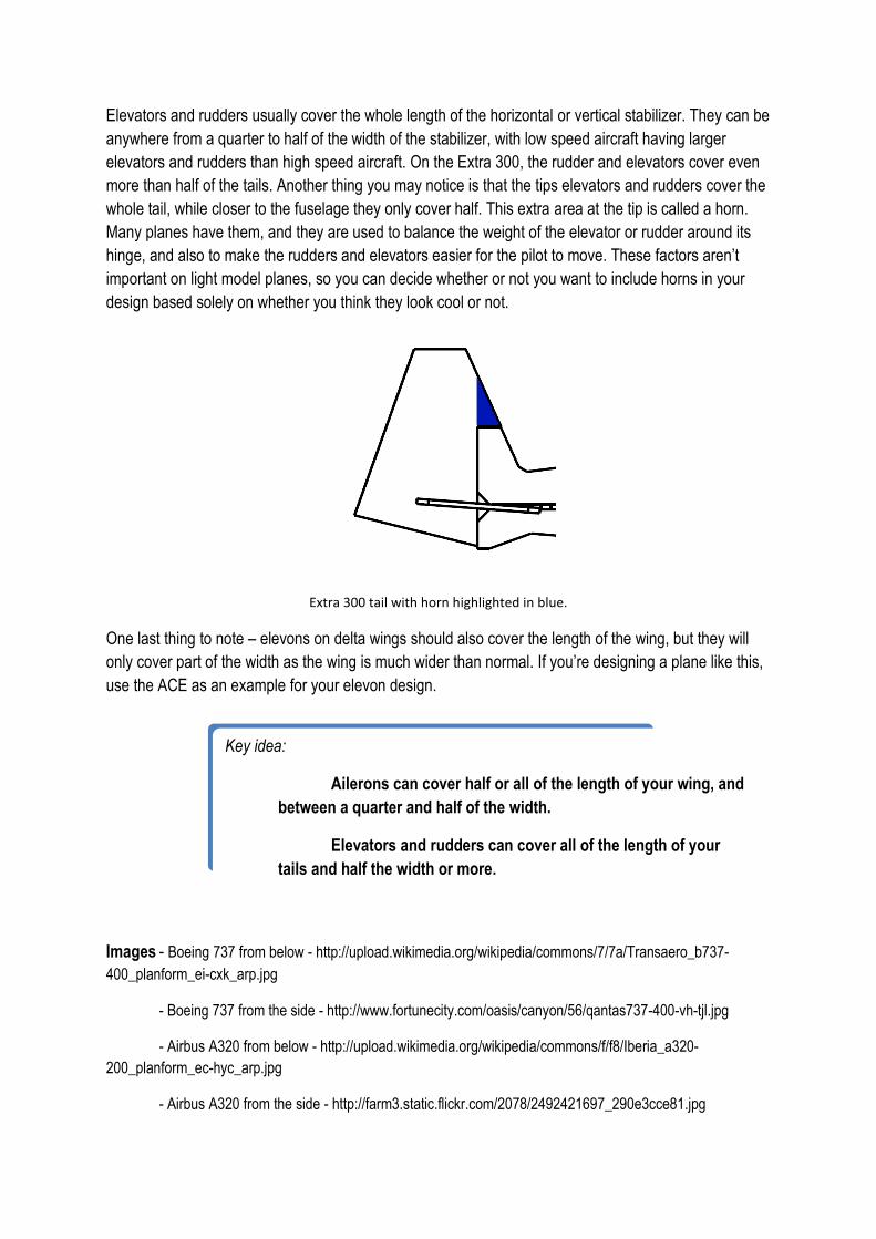
Elevators and rudders usually cover the whole length of the horizontal or vertical stabilizer. They can be
anywhere from a quarter to half of the width of the stabilizer, with low speed aircraft having larger
elevators and rudders than high speed aircraft. On the Extra 300, the rudder and elevators cover even
more than half of the tails. Another thing you may notice is that the tips elevators and rudders cover the
whole tail, while closer to the fuselage they only cover half. This extra area at the tip is called a horn.
Many planes have them, and they are used to balance the weight of the elevator or rudder around its
hinge, and also to make the rudders and elevators easier for the pilot to move. These factors aren’t
important on light model planes, so you can decide whether or not you want to include horns in your
design based solely on whether you think they look cool or not.
Extra 300 tail with horn highlighted in blue.
One last thing to note – elevons on delta wings should also cover the length of the wing, but they will
only cover part of the width as the wing is much wider than normal. If you’re designing a plane like this,
use the ACE as an example for your elevon design.
Images - Boeing 737 from below - http://upload.wikimedia.org/wikipedia/commons/7/7a/Transaero_b737-
400_planform_ei-cxk_arp.jpg
- Boeing 737 from the side - http://www.fortunecity.com/oasis/canyon/56/qantas737-400-vh-tjl.jpg
- Airbus A320 from below - http://upload.wikimedia.org/wikipedia/commons/f/f8/Iberia_a320-
200_planform_ec-hyc_arp.jpg
- Airbus A320 from the side - http://farm3.static.flickr.com/2078/2492421697_290e3cce81.jpg
Key idea:
Ailerons can cover half or all of the length of your wing, and
between a quarter and half of the width.
Elevators and rudders can cover all of the length of your
tails and half the width or more.
Advanced concept:
Designing Canards
Canards, which we mentioned in Learning Module 3, are horizontal stabilizers
placed at the front of a plane. The Wright Flyer, the first successful powered
aircraft, had canards, as did a few other early designs, but the conventional tail
configuration became the most used. Canards are still seen occasionally,
particularly on high speed fighter jets. Canards can range from small surfaces
used for control to large surfaces nearly as big as the main wing used to
generate lift. We will focus on small control canards, as these are easier to
design.
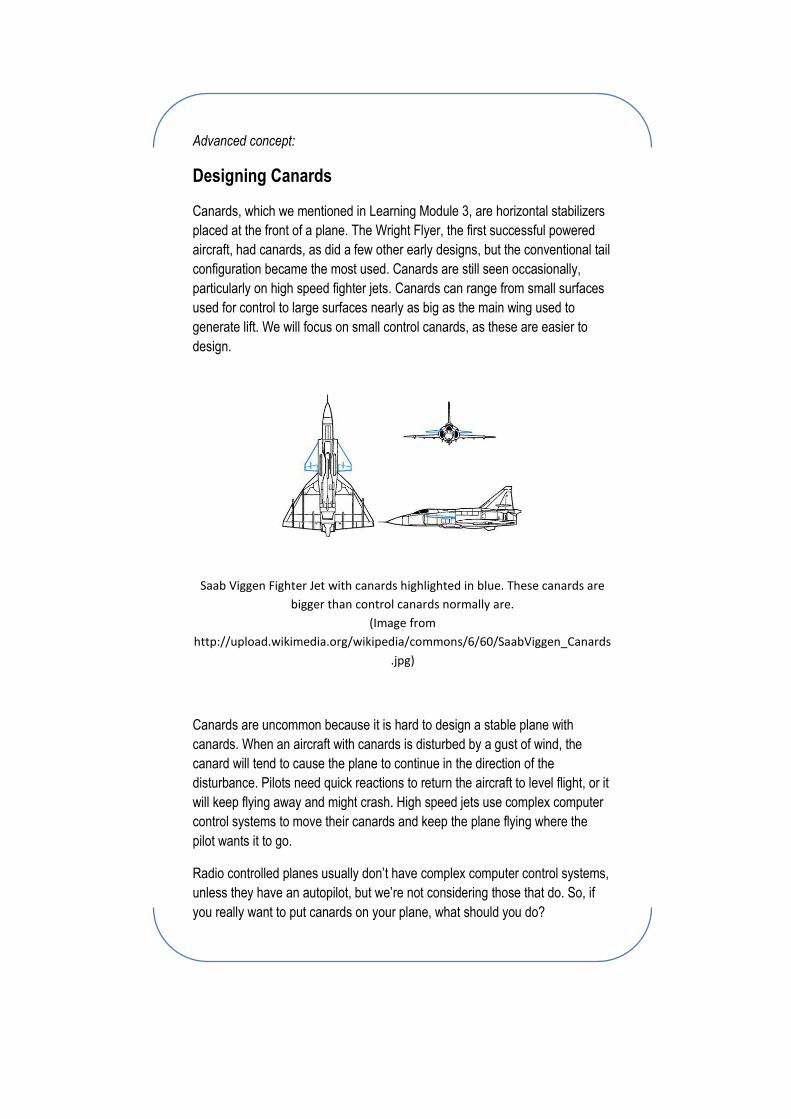
Saab Viggen Fighter Jet with canards highlighted in blue. These canards are
bigger than control canards normally are.
(Image from
http://upload.wikimedia.org/wikipedia/commons/6/60/SaabViggen_Canards
.jpg)
Canards are uncommon because it is hard to design a stable plane with
canards. When an aircraft with canards is disturbed by a gust of wind, the
canard will tend to cause the plane to continue in the direction of the
disturbance. Pilots need quick reactions to return the aircraft to level flight, or it
will keep flying away and might crash. High speed jets use complex computer
control systems to move their canards and keep the plane flying where the
pilot wants it to go.
Radio controlled planes usually don’t have complex computer control systems,
unless they have an autopilot, but we’re not considering those that do. So, if
you really want to put canards on your plane, what should you do?
Well, some of the tail design principles are the same and some are reversed.
The canards should be close to the nose of the aircraft. If you’re putting
canards on your plane you may need to put the engine at the back, or place
the battery a long way back, so that the centre of gravity will still be near the
start of your wing. Your wing will also be further back along the plane, and you
might have to make your vertical tail bigger because it will be close to the
centre of gravity (remember that you can’t put it at the front.)
The size of your canard should be chosen the same way that the size of a tail
is chosen, by looking at similar planes. Obviously these planes must have
canards. Looking at other planes will also give you an idea of what shape your
canards should be, but you can choose this yourself if you prefer.
Small control canards on fighter jets often rotate as a single piece, rather than
having a separate elevator. This is hard to do with a radio controlled plane, so I
suggest you place elevators on the back end of your canards. Like normal
elevators, they should cover the whole length and about half the width of the
canard. You can use horns if you like the look, but they would be unusual in a
canard.
I suggest that you don’t try a canard design on your first plane. You might even
like to put canards on that don’t move and fly the plane with elevons. If you do
use canards, be prepared for lots of crashes and a hard time flying in a straight
line. But if you don’t try it you’ll never succeed so good luck!
Learning Module 7
How powerful should my motor be?
Airplane engines are often the most complex single component in the aircraft. It takes as much time
and money to develop a new engine as it does to develop a new plane and almost all planes are
designed to fit existing engines. Model plane engine design is somewhat simpler, as a large number of
engines are available on the market to fit almost any requirement. We’ll briefly look at how professional
airplane designers choose an engine, and then look at how to choose the right engine, propeller and
everything else for our model planes.
Traditional Aircraft Design
The traditional aircraft design process is somewhat different to what we’ve outlined here in these
Learning Modules. The first step in aircraft design is to determine how much a plane will weigh. This
may seem unusual, but an aircraft’s weight is very important, and can actually tell a lot about what a
plane is designed to do. The weight is determined by working out what the plane should do – how far it
needs to fly, how many passengers it needs to carry, how many turns and manoeuvres it needs to do –
and comparing the plane to other planes designed to do similar things. This process tells the designers
how much the plane will weigh, how much fuel it needs to carry, and how many passengers/how much
cargo it can carry.
Once an estimate of the plane’s weight is found, the designer will analyse a number of flight conditions
to work out how big the wing should be and how big the motor should be. There are a number of rules
about how quickly a plane needs to be able to climb, how high it should fly and a number of other
things. These rules are set by aviation lawmakers like CASA (Civil Aviation Safety Authority) in
Australia and FAA (Federal Aviation Administration) in America, and they determine how powerful
airplane engines should be. Designers also look at the airports their plane should be able to take off
from and work out how long the runways are. Shorter runways usually need planes with bigger wings
and more powerful engines. Very short runways, like those found on aircraft carriers, use powerful
catapults to launch planes and arresting wires to slow them down on landing, and planes need to be
designed specially to suit these.
This process tells designers how powerful their engine needs to be. Usually, they will then select an
engine that produces enough thrust to satisfy these requirements. If the available engines are not
powerful enough, they may have to change a few things about their design to make it lighter. They
might decrease the range, which decreases the amount of fuel the plane needs to carry. Sometimes
designers have a specific engine in mind before they begin design, in which case the whole process will
revolve around this engine, and other things like range, passengers and performance (maximum speed,
how high it flies etc) will be adjusted to fit the engine. Whether a specific engine is chosen or not, the
designer will have already decided on an engine type. This will be either a piston engine, like in a car,
driving a propeller, or a jet engine. The jet engine may also drive a propeller, or it may just accelerate
air by heating it. The choice of engine will affect the planes that the designer compares their design too
during the first step of determining how much the plane will weigh. Once the engine is chosen, other
details like where to mount the engine, where to put fuel tanks and what controls the pilot needs will be
worked out during the rest of the design process.
Model Planes
The process for designing a model plane, as we’ve seen, can be somewhat different. Many engines are
available, and so specific engine choice can be left quite late in the process. One decision that should
be made early, though, is what type of engine to use. Model planes can be built using small jet engines,
but these planes often cost as much as $30,000 or more and require expertise, very careful
construction and a very good pilot. For a long time, the most popular engine was a small piston engine,
like the engines used in cars, lawnmowers and many other common machines. Piston engines,
compared to jet engines, are simple and safe. The engines use petrol, which allows the planes to fly a
long time on a small, light tank. Recently, electric motors have become popular with small aircraft fliers.
Electric motors are even simpler and safer than piston engines. They are also easier to mount on a
plane, as they are lighter, and they can be more responsive than piston engines. They are often
cheaper than piston engines and usually much quieter. Electric motors do not provide as much flight
time, as batteries are heavier than fuel compared to the amount of energy they can provide, but
batteries are rechargeable. We will be focusing on electric motors here, as these are most suited to the
simple foam aircraft you’ll be building. First, we will choose the right propeller.
Propeller selection
Propellers come in many different sizes and shapes, and selecting the right one can be difficult. The
first thing to do is to decide how fast you want your plane to go. You may have decided this already
when you chose what type of plane to build (see Learning Module 3). If you want to make a fast plane,
like a model jet fighter or passenger jet, you will want a small propeller that spins very fast. If you want
to make a slower plane, like an acrobatic stunt plane, you’ll want a larger propeller that spins slowly.
This might seem unusual; surely a big propeller works better and pulls faster? Well, it’s not necessarily
the case. Big propellers move more air every time they rotate, but this air provides resistance. This
means the motor that turns it must be very strong. As it turns out, you can have a strong motor that
turns slowly or a weaker motor that turns quickly, but we’ll discuss this later. Make sure you select a
propeller designed for electric motors. If you want the motor at the front, select a normal propeller but if
you want it at the back you’ll need to get a different type of propeller called a pusher.
Propeller sizes are listed in inches, and usually have to numbers. The first number will tell you the
diameter of the propeller, which is how long it is from tip to tip. The second number is called the pitch.
The definition of pitch is confusing, but it is an indication of how steep the propeller is. A propeller with a
pitch of 0 would be completely flat, and the higher the pitch the more the blades are rotated. A high
pitch propeller will pull more air through each time it turns, but it will need a stronger motor. For
example, an 8x5 propeller has a diameter of 8 inches and a pitch of 5 inches, so it will need a stronger
motor than an 8x4 propeller.
If you want to make a fast plane, try a 6x4 propeller. You could experiment a bit with different diameters
and pitches (bigger or smaller), but this is a good place to start. A smaller propeller might make your
plane go faster, but a larger one will make it accelerate faster.
If you want to make a slow plane that can do plenty of tricks, try a 10x3.8 or 10x4.7 propeller. Once
again you can experiment with this; a 9 inch diameter will go a little bit faster but may not climb quite as
well.
Motor Selection
Once you’ve picked your propeller, you need to find a motor to turn it. As we mentioned earlier, motors
are usually designed to be strong and slow turning or weak and fast turning. The power of a motor is
the strength of the motor multiplied by the speed it turns, so two motors with the same power could be
designed for completely different things, one turning fast and the other slow. Large propellers need
strong, slow turning motors and small propellers need weaker, faster turning motors. With regard to
size, you will probably use a motor that takes in about 100 Watts or more. If the motor manufacturer
doesn’t list the wattage, multiply the voltage required (probably 11.1 Volts, see the battery section) by
the current drawn (anywhere from 9 to 14ish Amps should be ok) and this will give you your power
rating in watts. The motor you should get is called a “Brushless Outrunner.” These motors are more
efficient than brushed motors and they spin slower, so they can be attached directly to propellers
without needing a gearbox.
The kV rating of a motor is used to determine whether the motor should be used for strong, slow turning
or weak, fast turning. The higher the kV the faster and weaker the motor will turn. Motors will usually
indicate what size propeller they are designed to work with. If you’re looking at an online store, a
number of details will be shown with the motor, and this should include a suggested propeller size. As a
guideline, fast planes with 6x4 propellers should have a motor around 2200 kV (2000-2400 should be
ok) and slow planes with 10x3.8/10x4.7 propellers should have a motor around 1000 kV (800-1200
should be ok).
The motor should also tell you what size ESC you need. An ESC, or Electronic Speed Controller, is a
small electronic circuit that controls the motor. The ESC connects to the battery and the radio receiver.
It takes the throttle command that you select on your radio transmitter and runs the motor at the right
Key idea:
An XxY propeller has a diameter of X inches and a pitch of Y
inches, where higher pitch needs a stronger motor.
Fast planes should have small propellers like 6x4s
Slow planes should have large propellers like 10x3.8s
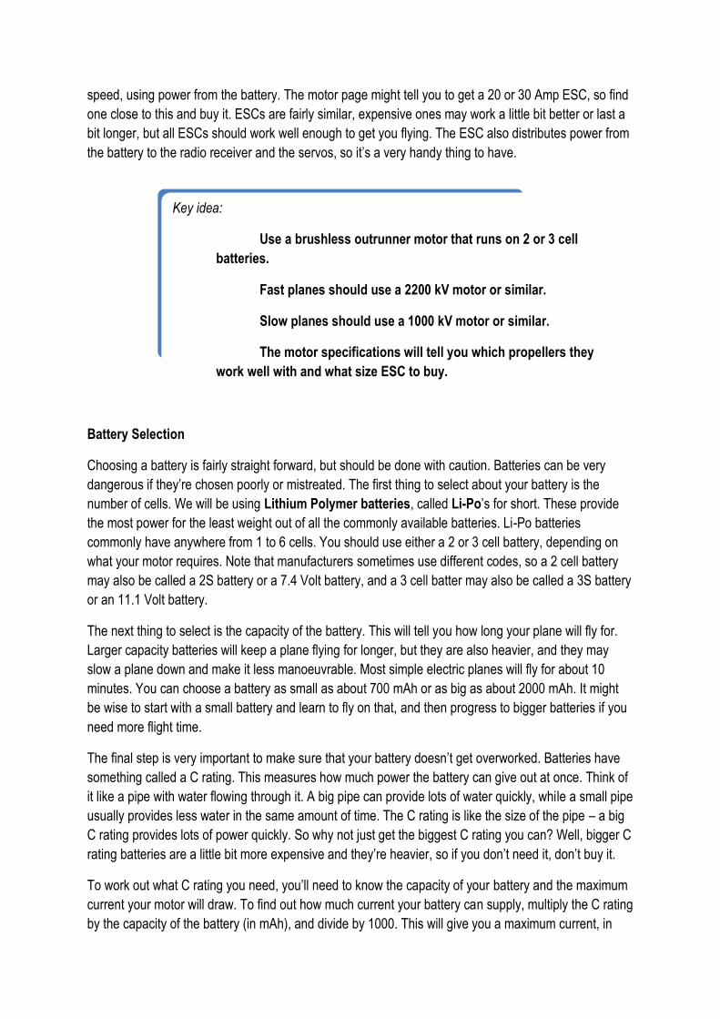
speed, using power from the battery. The motor page might tell you to get a 20 or 30 Amp ESC, so find
one close to this and buy it. ESCs are fairly similar, expensive ones may work a little bit better or last a
bit longer, but all ESCs should work well enough to get you flying. The ESC also distributes power from
the battery to the radio receiver and the servos, so it’s a very handy thing to have.
Battery Selection
Choosing a battery is fairly straight forward, but should be done with caution. Batteries can be very
dangerous if they’re chosen poorly or mistreated. The first thing to select about your battery is the
number of cells. We will be using Lithium Polymer batteries, called Li-Po’s for short. These provide
the most power for the least weight out of all the commonly available batteries. Li-Po batteries
commonly have anywhere from 1 to 6 cells. You should use either a 2 or 3 cell battery, depending on
what your motor requires. Note that manufacturers sometimes use different codes, so a 2 cell battery
may also be called a 2S battery or a 7.4 Volt battery, and a 3 cell batter may also be called a 3S battery
or an 11.1 Volt battery.
The next thing to select is the capacity of the battery. This will tell you how long your plane will fly for.
Larger capacity batteries will keep a plane flying for longer, but they are also heavier, and they may
slow a plane down and make it less manoeuvrable. Most simple electric planes will fly for about 10
minutes. You can choose a battery as small as about 700 mAh or as big as about 2000 mAh. It might
be wise to start with a small battery and learn to fly on that, and then progress to bigger batteries if you
need more flight time.
The final step is very important to make sure that your battery doesn’t get overworked. Batteries have
something called a C rating. This measures how much power the battery can give out at once. Think of
it like a pipe with water flowing through it. A big pipe can provide lots of water quickly, while a small pipe
usually provides less water in the same amount of time. The C rating is like the size of the pipe – a big
C rating provides lots of power quickly. So why not just get the biggest C rating you can? Well, bigger C
rating batteries are a little bit more expensive and they’re heavier, so if you don’t need it, don’t buy it.
To work out what C rating you need, you’ll need to know the capacity of your battery and the maximum
current your motor will draw. To find out how much current your battery can supply, multiply the C rating
by the capacity of the battery (in mAh), and divide by 1000. This will give you a maximum current, in
Key idea:
Use a brushless outrunner motor that runs on 2 or 3 cell
batteries.
Fast planes should use a 2200 kV motor or similar.
Slow planes should use a 1000 kV motor or similar.
The motor specifications will tell you which propellers they
work well with and what size ESC to buy.
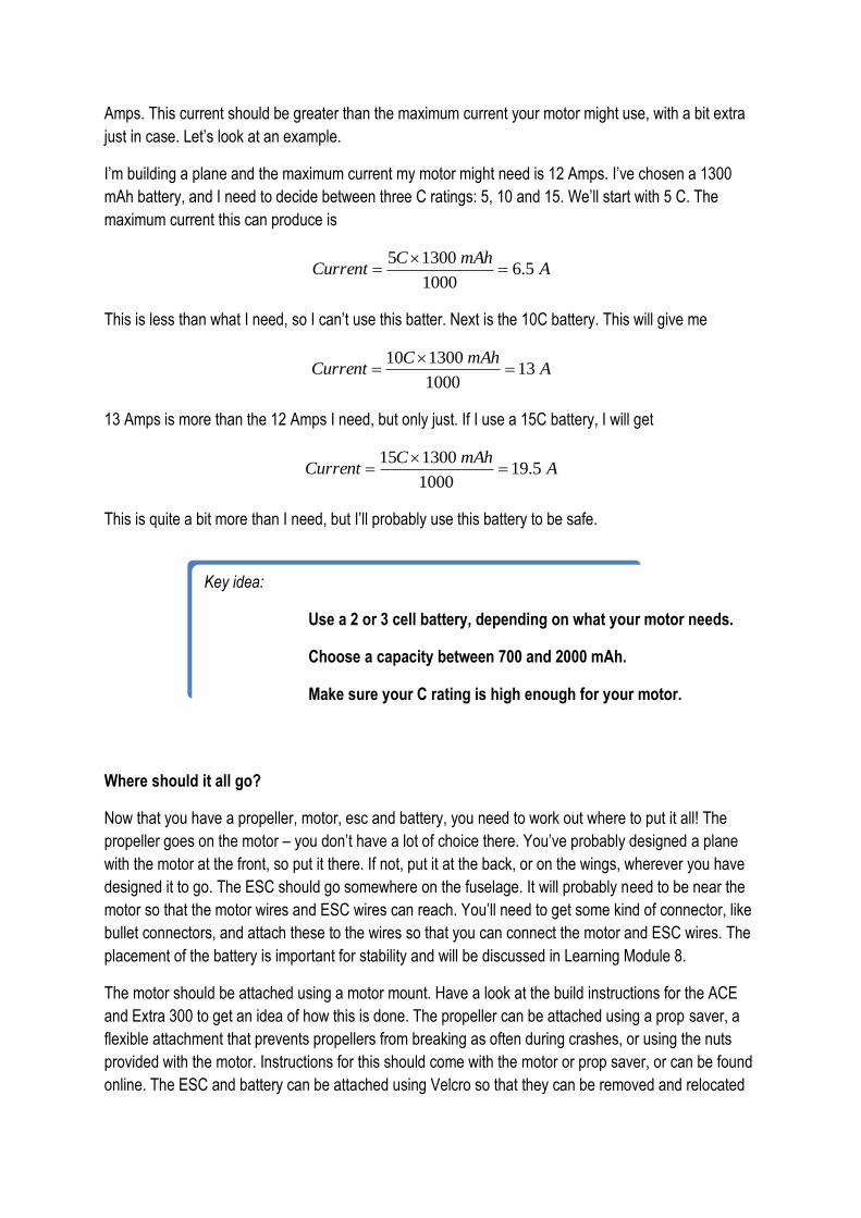
Amps. This current should be greater than the maximum current your motor might use, with a bit extra
just in case. Let’s look at an example.
I’m building a plane and the maximum current my motor might need is 12 Amps. I’ve chosen a 1300
mAh battery, and I need to decide between three C ratings: 5, 10 and 15. We’ll start with 5 C. The
maximum current this can produce is
AmAhC
Current 5.61000
13005
This is less than what I need, so I can’t use this batter. Next is the 10C battery. This will give me
AmAhC
Current 131000
130010
13 Amps is more than the 12 Amps I need, but only just. If I use a 15C battery, I will get
AmAhC
Current 5.191000
130015
This is quite a bit more than I need, but I’ll probably use this battery to be safe.
Where should it all go?
Now that you have a propeller, motor, esc and battery, you need to work out where to put it all! The
propeller goes on the motor – you don’t have a lot of choice there. You’ve probably designed a plane
with the motor at the front, so put it there. If not, put it at the back, or on the wings, wherever you have
designed it to go. The ESC should go somewhere on the fuselage. It will probably need to be near the
motor so that the motor wires and ESC wires can reach. You’ll need to get some kind of connector, like
bullet connectors, and attach these to the wires so that you can connect the motor and ESC wires. The
placement of the battery is important for stability and will be discussed in Learning Module 8.
The motor should be attached using a motor mount. Have a look at the build instructions for the ACE
and Extra 300 to get an idea of how this is done. The propeller can be attached using a prop saver, a
flexible attachment that prevents propellers from breaking as often during crashes, or using the nuts
provided with the motor. Instructions for this should come with the motor or prop saver, or can be found
online. The ESC and battery can be attached using Velcro so that they can be removed and relocated
Key idea:
Use a 2 or 3 cell battery, depending on what your motor needs.
Choose a capacity between 700 and 2000 mAh.
Make sure your C rating is high enough for your motor.
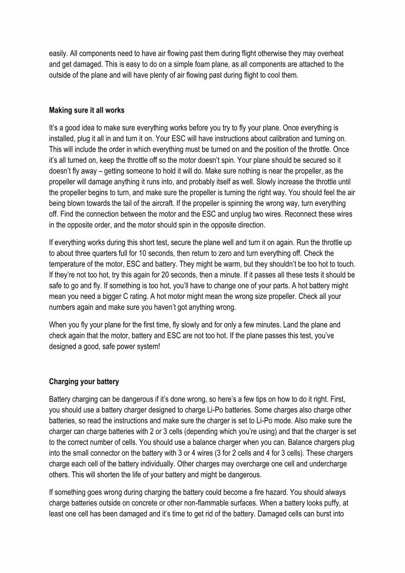
easily. All components need to have air flowing past them during flight otherwise they may overheat
and get damaged. This is easy to do on a simple foam plane, as all components are attached to the
outside of the plane and will have plenty of air flowing past during flight to cool them.
Making sure it all works
It’s a good idea to make sure everything works before you try to fly your plane. Once everything is
installed, plug it all in and turn it on. Your ESC will have instructions about calibration and turning on.
This will include the order in which everything must be turned on and the position of the throttle. Once
it’s all turned on, keep the throttle off so the motor doesn’t spin. Your plane should be secured so it
doesn’t fly away – getting someone to hold it will do. Make sure nothing is near the propeller, as the
propeller will damage anything it runs into, and probably itself as well. Slowly increase the throttle until
the propeller begins to turn, and make sure the propeller is turning the right way. You should feel the air
being blown towards the tail of the aircraft. If the propeller is spinning the wrong way, turn everything
off. Find the connection between the motor and the ESC and unplug two wires. Reconnect these wires
in the opposite order, and the motor should spin in the opposite direction.
If everything works during this short test, secure the plane well and turn it on again. Run the throttle up
to about three quarters full for 10 seconds, then return to zero and turn everything off. Check the
temperature of the motor, ESC and battery. They might be warm, but they shouldn’t be too hot to touch.
If they’re not too hot, try this again for 20 seconds, then a minute. If it passes all these tests it should be
safe to go and fly. If something is too hot, you’ll have to change one of your parts. A hot battery might
mean you need a bigger C rating. A hot motor might mean the wrong size propeller. Check all your
numbers again and make sure you haven’t got anything wrong.
When you fly your plane for the first time, fly slowly and for only a few minutes. Land the plane and
check again that the motor, battery and ESC are not too hot. If the plane passes this test, you’ve
designed a good, safe power system!
Charging your battery
Battery charging can be dangerous if it’s done wrong, so here’s a few tips on how to do it right. First,
you should use a battery charger designed to charge Li-Po batteries. Some charges also charge other
batteries, so read the instructions and make sure the charger is set to Li-Po mode. Also make sure the
charger can charge batteries with 2 or 3 cells (depending which you’re using) and that the charger is set
to the correct number of cells. You should use a balance charger when you can. Balance chargers plug
into the small connector on the battery with 3 or 4 wires (3 for 2 cells and 4 for 3 cells). These chargers
charge each cell of the battery individually. Other charges may overcharge one cell and undercharge
others. This will shorten the life of your battery and might be dangerous.
If something goes wrong during charging the battery could become a fire hazard. You should always
charge batteries outside on concrete or other non-flammable surfaces. When a battery looks puffy, at
least one cell has been damaged and it’s time to get rid of the battery. Damaged cells can burst into
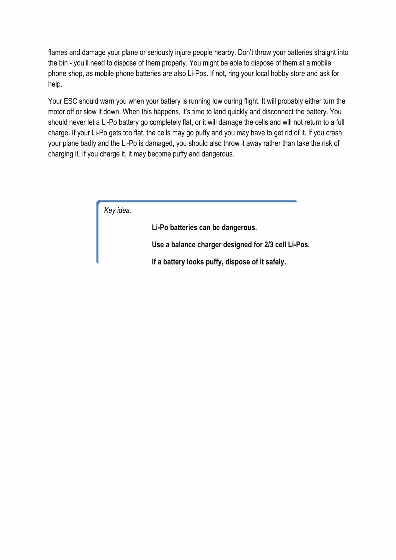
flames and damage your plane or seriously injure people nearby. Don’t throw your batteries straight into
the bin - you’ll need to dispose of them properly. You might be able to dispose of them at a mobile
phone shop, as mobile phone batteries are also Li-Pos. If not, ring your local hobby store and ask for
help.
Your ESC should warn you when your battery is running low during flight. It will probably either turn the
motor off or slow it down. When this happens, it’s time to land quickly and disconnect the battery. You
should never let a Li-Po battery go completely flat, or it will damage the cells and will not return to a full
charge. If your Li-Po gets too flat, the cells may go puffy and you may have to get rid of it. If you crash
your plane badly and the Li-Po is damaged, you should also throw it away rather than take the risk of
charging it. If you charge it, it may become puffy and dangerous.
Key idea:
Li-Po batteries can be dangerous.
Use a balance charger designed for 2/3 cell Li-Pos.
If a battery looks puffy, dispose of it safely.
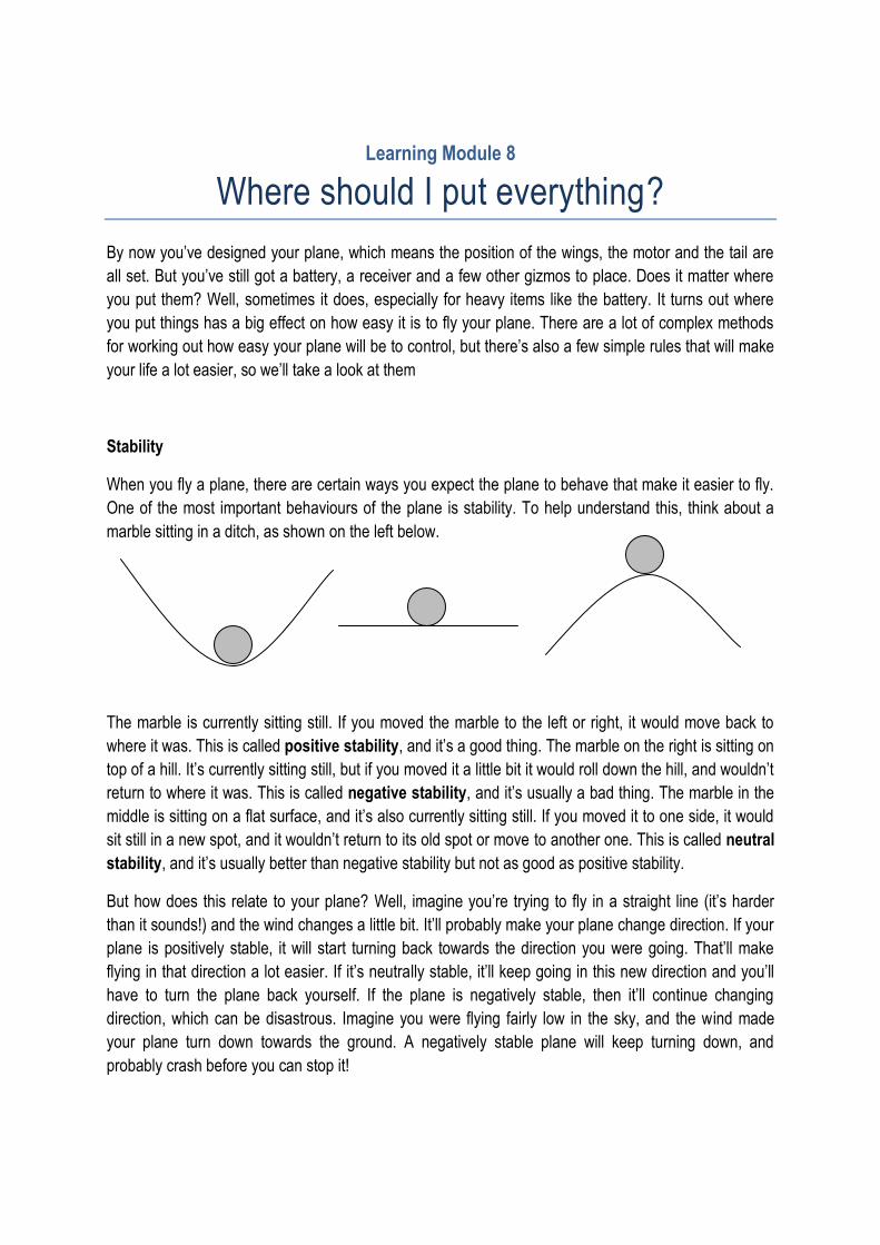
Learning Module 8
Where should I put everything?
By now you’ve designed your plane, which means the position of the wings, the motor and the tail are
all set. But you’ve still got a battery, a receiver and a few other gizmos to place. Does it matter where
you put them? Well, sometimes it does, especially for heavy items like the battery. It turns out where
you put things has a big effect on how easy it is to fly your plane. There are a lot of complex methods
for working out how easy your plane will be to control, but there’s also a few simple rules that will make
your life a lot easier, so we’ll take a look at them
Stability
When you fly a plane, there are certain ways you expect the plane to behave that make it easier to fly.
One of the most important behaviours of the plane is stability. To help understand this, think about a
marble sitting in a ditch, as shown on the left below.
The marble is currently sitting still. If you moved the marble to the left or right, it would move back to
where it was. This is called positive stability, and it’s a good thing. The marble on the right is sitting on
top of a hill. It’s currently sitting still, but if you moved it a little bit it would roll down the hill, and wouldn’t
return to where it was. This is called negative stability, and it’s usually a bad thing. The marble in the
middle is sitting on a flat surface, and it’s also currently sitting still. If you moved it to one side, it would
sit still in a new spot, and it wouldn’t return to its old spot or move to another one. This is called neutral
stability, and it’s usually better than negative stability but not as good as positive stability.
But how does this relate to your plane? Well, imagine you’re trying to fly in a straight line (it’s harder
than it sounds!) and the wind changes a little bit. It’ll probably make your plane change direction. If your
plane is positively stable, it will start turning back towards the direction you were going. That’ll make
flying in that direction a lot easier. If it’s neutrally stable, it’ll keep going in this new direction and you’ll
have to turn the plane back yourself. If the plane is negatively stable, then it’ll continue changing
direction, which can be disastrous. Imagine you were flying fairly low in the sky, and the wind made
your plane turn down towards the ground. A negatively stable plane will keep turning down, and
probably crash before you can stop it!

Too much of a good thing
As you saw from the previous example, a positively stable plane is a good thing. However, you can
have too much stability in your plane. If your plane is very stable, it will produce very strong forces to
keep it flying the way that it is. But when you want to change direction, to climb or turn around for
example, it will take a lot of effort to overcome these forces. Because of that, the plane will be very slow
to turn, and it will be hard to fly.
How stable should your plane be? It depends what you want your plane to do! If you’re learning to fly,
you want a stable, slow plane to practice on. But as you get better at flying, you can make your plane
less stable so that it turns quicker and can do more tricks. Some types of plane, like acrobatic planes
and jet fighters, need to be very quick at turning, so they are designed to be less stable (see Learning
Module 3). Sometimes, modern fighters are even designed with negative stability to turn very quickly.
While a human pilot could not safely fly an aircraft like this, computer control systems are a lot quicker
than human pilots. They can detect when the aircraft is heading the wrong direction and turn it back in a
split second. Using these control systems, humans can now safely fly aircraft that would’ve been
impossible to fly 50 years ago.
So how do you change how stable your aircraft is? There are many factors that affect the stability of an
aircraft, but one simple factor that you can control is the weight balance of the aircraft. To understand
that, we’ll need to look at something called the centre of gravity.
Centre of Gravity
When you try to balance a ruler on your finger, you put your finger near the middle so that the weight of
the ruler to the left of your finger equals the weight on the right. (Go on, try it now!) The centre of
gravity is the point where you can put your finger to make the ruler balance. Now, if you put something
heavy, like an eraser, on one end, the ruler will no longer balance near the middle. You’ll have to move
your finger closer to the end with the eraser. The centre of gravity has now moved towards the heavy
object.
This is the same approach we use to change the centre of gravity on your plane. Think of your plane as
a ruler, and your battery as an eraser. (We’re using the battery because it’s the heaviest part, so it’ll
have the biggest effect on the centre of gravity) If you pick up your plane by pinching somewhere along
the top, you’ll probably notice that one end drops down. Move your fingers closer to the low end and it
will droop less. Continue this until your plane doesn’t droop too much either way, and you’ll have a
Key idea:
Positively stable planes are much easier to fly because they
continue flying in one direction.
Negatively stable planes are hard to control.
rough idea of where your centre of gravity is. Now, if the middle of your battery is in front of this, the
centre of gravity will move forwards, and if it’s behind it’ll move backwards.
So now you know what your centre of gravity is and how to change it. But how does this affect the
stability of your plane? The how is quite simple, but the why is a little more complicated. We’ll talk about
the how now, and we’ll have a brief look at the why in the advanced concept later on.
A stable plane
You’ve probably noticed that paper planes fly better when you put something heavy, like a paper clip,
on their nose. This moves the centre of gravity forwards, making the plane more stable. To make a
plane stable, the centre of gravity should be near the nose of the aircraft. If your plane has a normal
configuration, it should be near the front of the wing, or even further forward. The closer the centre of
gravity is to the nose, the more stable your aircraft will be. This isn’t the only thing that affects stability,
but it’s one of the most important and one of the easiest to control. It can also be changed once you’ve
built your plane. If you mount your battery using Velcro and have a long strip on the plane, you can
move the battery backwards and forwards to adjust the centre of gravity.
So, where is the right spot? Well, you could do a bunch of maths to help you make an educated guess,
but it’s easier to work it out with a few flight tests. It’s a whole lot more fun too! First, put the battery
quite close to the nose, and check that your centre of gravity is quite far forward. Then, take it for a
flight! You should find that it’s very stable, but it might be too stable. If it takes too much effort to fly or
you think you’d rather have it turn faster, move the battery back a little and fly it again. If it turns too
quickly and you keep crashing, you’ll need to move the battery forward again. Using this simple
procedure you can find a configuration that works well for you. Most people find that having the CG
about a quarter of the wing width behind the front edge of the wing is a good place to start.
Now, we’ve only discussed something called longitudinal stability. There are other types of stability, but
these aren’t usually a problem for radio controlled planes. However, another important design principle
is to keep your plane as close to symmetrical along the centre as possible. This means the left half and
the right half have the same size wing and tails in the same position, and the motor is in the middle. It
also means you should put other things like your battery and receivers as near to the middle as
possible. You probably won’t be able to get it perfect, but near enough should be good enough.
Key idea:
The further forward the centre of gravity is the more stable
the plane will be.
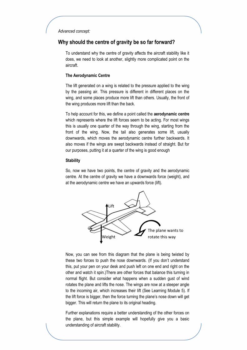
Advanced concept:
Why should the centre of gravity be so far forward?
To understand why the centre of gravity affects the aircraft stability like it
does, we need to look at another, slightly more complicated point on the
aircraft.
The Aerodynamic Centre
The lift generated on a wing is related to the pressure applied to the wing
by the passing air. This pressure is different in different places on the
wing, and some places produce more lift than others. Usually, the front of
the wing produces more lift than the back.
To help account for this, we define a point called the aerodynamic centre
which represents where the lift forces seem to be acting. For most wings
this is usually one quarter of the way through the wing, starting from the
front of the wing. Now, the tail also generates some lift, usually
downwards, which moves the aerodynamic centre further backwards. It
also moves if the wings are swept backwards instead of straight. But for
our purposes, putting it at a quarter of the wing is good enough
Stability
So, now we have two points, the centre of gravity and the aerodynamic
centre. At the centre of gravity we have a downwards force (weight), and
at the aerodynamic centre we have an upwards force (lift).
Now, you can see from this diagram that the plane is being twisted by
these two forces to push the nose downwards. (If you don’t understand
this, put your pen on your desk and push left on one end and right on the
other and watch it spin.)There are other forces that balance this turning in
normal flight. But consider what happens when a sudden gust of wind
rotates the plane and lifts the nose. The wings are now at a steeper angle
to the incoming air, which increases their lift (See Learning Module 5). If
the lift force is bigger, then the force turning the plane’s nose down will get
bigger. This will return the plane to its original heading.
Further explanations require a better understanding of the other forces on
the plane, but this simple example will hopefully give you a basic
understanding of aircraft stability.
Lift
Weight
The plane wants to
rotate this way
Further Reading
Beginner’s Guide to Aeronautics
http://www.grc.nasa.gov/WWW/K-12/airplane/index.html
This website was made by NASA to educate American primary and secondary school students. It
covers everything you could want to know about how planes fly, from a basic introductory level through
to early university level studies. This site doesn’t have much specifically applied to aircraft design, but
many aircraft design resources will assume you know more than you probably will. If you find a concept
you don’t understand, this is a great place to find an explanation.
Perfect Park Flyer Power Systems
http://www.rcpowers.com/e-books.htm
This is an e-book written by someone who knows a lot about model planes, especially simple ones
made from foam. The book covers everything you need to know about power systems and was one of
the main inspirations for Learning Module 7. The forums on the site are also worth visiting. The Extra
300 plans come from here and there’s a build guide online to help you out, as well as lots of advice
from people who’ve tried new things and failed.
Simplified Aircraft Design for Homebuilders
Book by Daniel Raymer
This book is written for people who want to build their own plane. It’s intended for building full size,
flyable planes, but it makes an interesting read. Things are presented as simply as possible. A copy of
this book can be found at the University of Adelaide Library.
Aircraft Design: A Conceptual Approach
Textbook by Daniel Raymer
This is the older brother of the last book – one of the standard textbooks on Aircraft Design taught
around the world. The book is well written but it’s aimed at more advanced users, so it will be a hard
read for high schoolers. This textbook is available at the University of Adelaide Library, and is
recommended for advanced year 11 or 12 students doing extended projects in aircraft design.
Project Suggestions
Students looking to research specific aspects of aircraft design or performance might like to consider
one of these areas. Finding a mentor to help out will be essential – a good place to look would be
university students, recent graduates or old radio controlled aircraft veterans.
General Airfoils
There’s a lot that can be learnt about airfoils. The planes in this book usually use flat wing sections,
which are far from efficient. Students can look at how airfoils work and what different airfoils are
designed to do. Depending on resources, they could test different airfoil designs. Wings with airfoil
sections are harder to manufacture, but this may be within the scope of the project. A mentor will help a
lot with this, especially one with knowledge of the NACA airfoil classifications.
Specific resources – Javafoil (http://www.mh-aerotools.de/airfoils/javafoil.htm)
This tool generates different airfoil shapes. These can be printed onto paper and used as templates for
construction. The tool also estimates lift, drag and pitching moment coefficients, which can be used to
compare airfoils.
KF Airfoils
KF airfoils, or Kline Fogleman airfoils, are a special type of airfoil first designed by experiments with
paper planes. KF airfoils are popular with radio controlled plane enthusiasts as they can be made from
layered sheets of foam. For example, a second sheet of foam is placed over the wing, covering the
front half of the wing. The front of this wing is then rounded using a hot wire. KF airfoils are much more
efficient than flat wings, and have a number of interesting properties. They could be studied alongside
other airfoils or on their own.
Specific resources – Search “KF Airfoils” on Google/Wikipedia
The current Wikipedia article gives a good introduction to the topic. It contains a picture of 8 different
types, with a list of their specifics and benefits. This picture was made by Richard Kline, one of the
inventors of the KF airfoil. Many RC forums have lots of information about KF airfoils.
Motor testing
By buying a few different motors/propellers, students can test different combinations to see which
provide more thrust, which use more power and which are the most efficient. Students can make a test
stand that holds their motor but is free to move in one direction. Using a spring-based force gauge, they
run the motor and see what force it produces. They can also use multimeters to find currents and
voltages, and draw conclusions about which motor/propeller combinations work best.
Specific resources – Valley View Secondary School
Projects like this have been done at Valley View, and details can be provided. Contact Bob Haskard at
Airplane structures
The airplanes referred to in this guide are made from sheets of foam. These are structurally simple and
strong enough for the job, but real aircraft structures (as well as larger models) are more complex.
Students could research, for example, the structure of an aircraft wing. They could learn about spars,
ribs, stringers and skinning. They could design their own wing out of balsa wood and test it to
destruction by placing weights along the wing. The aim could be to determine the strongest wing with
the lightest weight.
Specific resources – Wikipedia or NASA Beginner’s guide
Find a good overview of a wing structure. Find definitions for spar, rib, stringer and monocoque. Look at
drawings of plane wings and identify each component and the type of load it’s meant to take. Then find
some plans for a model plane wing built like this and experiment.
About the Author
This teaching series was written by me, Jonathan Dansie. I’ve just completed a double degree in
Aerospace Engineering and Computer Science, graduating with First Class Honours, and will be
working with DSTO (Defence Science and Technology Organisation) in Melbourne researching aircraft
flight mechanics. I graduated from the University of Adelaide.
During my final year, I wrote these lessons to accompany the construction guides put together by Joel
Phillips, a Design and Technology education student at the University of South Australia. Through this I
first encountered foam RC airplanes, and have been a fan ever since. I’ve also worked as a high school
tutor throughout my university education, and have a passion for educating high school students,
particularly in Mathematics, Physics and Chemistry.
I wish you all the best following these guides, and would love to hear feedback on how useful (or
otherwise!) they have been and what could be improved. Thanks for reading!
Jonathan Dansie