Embed Size (px)
Citation preview

Journal of Advanced Thermal Science Research, 2019, 6, 71-84 71
E-ISSN: 2409-5826/19 © 2019 Avanti Publishers
Experimental Characterization of Low-Temperature Inorganic. Phase Change Materials by Differential Scanning Calorimetry
Josh Charles1,2,*, Xingchao Wang2, Carlos E. Romero2 and Sudhakar Neti2
1Advanced Cooling Technologies, 1046 New Holland Ave., Lancaster, PA 17601, USA 2Lehigh University, Energy Research Center, 117 ATLSS Dr., Bethlehem, PA 18015, USA
Abstract: Recently, phase change materials (PCMs) have received significant attention due to their potential for high-density thermal energy storage. While high-temperature PCMs have received the most focus in the thermal energy storage community, there are potential uses for PCMs with phase transition temperatures close to typical ambient temperatures (15-35°C). For a PCM to be widely used in a large-scale thermal energy storage system, it must meet the cost, safety, and energy density criteria in addition to having an appropriate phase change temperature. Inorganic, hydrated salt PCMs are the most promising, low-temperature PCMs, which can meet all of these criteria. After completing a review of known inorganic PCMs with phase change temperatures in the desired range, six of the more promising PCMs were tested by differential scanning calorimetry (DSC) to determine both their phase change temperatures (Tm) and latent heats of fusion (Hf). The first of these PCMs (potassium fluoride tetrahydrate) was eliminated after successful DSC testing as it became apparent that this PCM had serious health and safety concerns. Two new calcium chloride hexahydrate (CaCl2·6H2O)-based PCMs were also tested: CaCl2·6H2O + potassium nitrate (KNO3) and CaCl2·6H2O + magnesium chloride hexahydrate (MgCl2·6H2O). For CaCl2·6H2O + KNO3, it was found that the melt temperature of the PCM could be varied by changing the percentage of KNO3. In the case of the CaCl2·6H2O + MgCl2·6H2O, phase diagram modeling and physical experiments were used to determine the correct eutectic mixture, which leads to congruent melting/freezing of this PCM. CaCl2·6H2O was also tested by DSC, with found Tm and Hf results similar to those presented in the literature. Finally, sodium sulfate decahydrate (Na2SO4·10H2O) and Na2SO4·10H2O + 25 wt% H2O were tested by DSC. For both of these PCMs, significant phase separation was observed, which must be addressed if these PCMs are to be used commercially.
Keywords: Latent energy storage, Phase change material, Energy storage, Hydrated salt, Calcium chloride hexahydrate, PCM.
INTRODUCTION
Thermal energy storage has been utilized by mankind for millennia. Most historic thermal energy storage techniques are based on sensible thermal energy storage – with one notable exception – the latent thermal energy transfer accompanying the melting or freezing of water. The high energy density of this phase change has made ice very useful for cooling everything, from drinks to early refrigerators. More recently, materials with a high solid/liquid phase change temperature (> 300°C) have begun to be used for storing thermal energy that is captured in large solar thermal power plants. In the late 1970’s and 1980’s, several researchers considered low-temperature phase change materials (PCMs) primarily for use in temperature regulation of buildings. This work was conducted by researchers such as Telkes [1], Lane [2,3], Carlsson [4], Abhat [5], and Kimura, [6-8] with their work forming the bulk of the seminal research into low-temperature PCMs. After little low-temperature PCM work in the 1990’s and early 2000’s, interest in the topic was renewed in the later years of the first decade of the 21st century. Since then many papers
*Address correspondence to this author at the Advanced Cooling Technologies, 1046 New Holland Ave., Lancaster, PA, 17601, USA; Tel: 717-205-0653; Fax: 717-295-6064; E-mail: [email protected]
have been published on the topic by the likes of N’Tsoukpoe [9,10], Tyagi [11,12], Carlsson [13], Sharma [14-16], and Oró [17] among others.
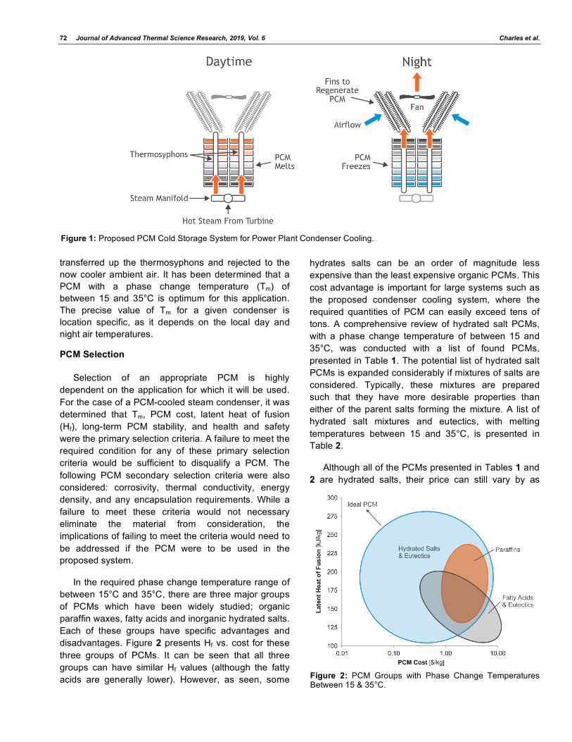
While there are numerous organic and inorganic low-temperature PCMs, inorganic hydrated salt PCMs are of particular interest due to their low cost and wide availability. The low-temperature PCM application considered in this paper is the use of a PCM for daytime supplemental cooling of main steam-condensers in power plants. The proposed system is illustrated in Figure 1. In this system, sealed trays of PCM are stacked vertically around centrally-located thermosyphons, which move thermal energy into and out of the PCM. During the day, hot steam from the last steam turbine stage is distributed to the bottoms of the thermosyphons in a manifold. Thermal energy from the steam is transferred to the PCM through the thermosyphons, where it melts the PCM. This system would be particularly beneficial for a power plant, which uses dry cooling (an air-cooled condenser) as the performance of these plants suffer on hot days, when thermal energy cannot be transferred efficiently to the air. By transferring the thermal energy from the steam into the PCM during melting, steam from the turbine is condensed at a lower temperature, which improves steam turbine power output. During the night, the PCM is frozen as thermal energy from the PCM is
72 Journal of Advanced Thermal Science Research, 2019, Vol. 6 Charles et al.
transferred up the thermosyphons and rejected to the now cooler ambient air. It has been determined that a PCM with a phase change temperature (Tm) of between 15 and 35°C is optimum for this application. The precise value of Tm for a given condenser is location specific, as it depends on the local day and night air temperatures.
PCM Selection
Selection of an appropriate PCM is highly dependent on the application for which it will be used. For the case of a PCM-cooled steam condenser, it was determined that Tm, PCM cost, latent heat of fusion (Hf), long-term PCM stability, and health and safety were the primary selection criteria. A failure to meet the required condition for any of these primary selection criteria would be sufficient to disqualify a PCM. The following PCM secondary selection criteria were also considered: corrosivity, thermal conductivity, energy density, and any encapsulation requirements. While a failure to meet these criteria would not necessary eliminate the material from consideration, the implications of failing to meet the criteria would need to be addressed if the PCM were to be used in the proposed system.
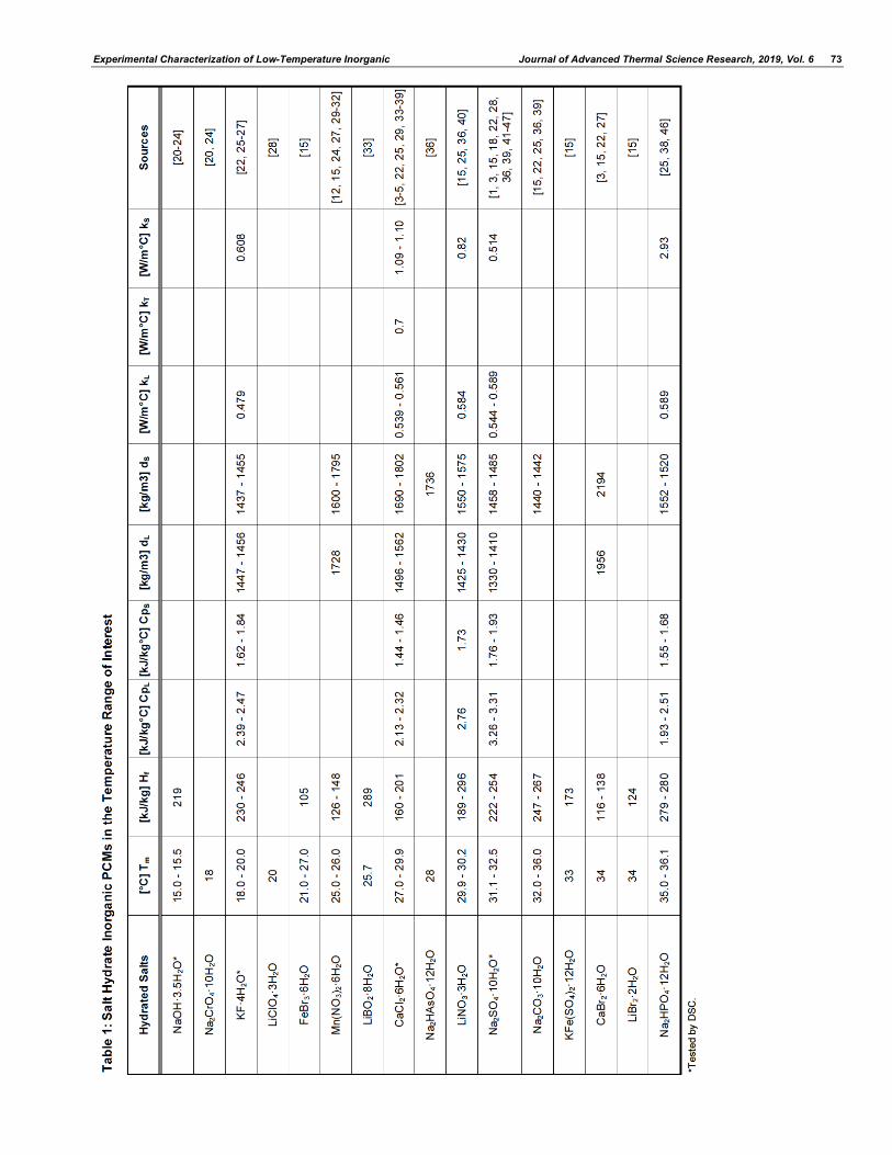
In the required phase change temperature range of between 15°C and 35°C, there are three major groups of PCMs which have been widely studied; organic paraffin waxes, fatty acids and inorganic hydrated salts. Each of these groups have specific advantages and disadvantages. Figure 2 presents Hf vs. cost for these three groups of PCMs. It can be seen that all three groups can have similar Hf values (although the fatty acids are generally lower). However, as seen, some
hydrates salts can be an order of magnitude less expensive than the least expensive organic PCMs. This cost advantage is important for large systems such as the proposed condenser cooling system, where the required quantities of PCM can easily exceed tens of tons. A comprehensive review of hydrated salt PCMs, with a phase change temperature of between 15 and 35°C, was conducted with a list of found PCMs, presented in Table 1. The potential list of hydrated salt PCMs is expanded considerably if mixtures of salts are considered. Typically, these mixtures are prepared such that they have more desirable properties than either of the parent salts forming the mixture. A list of hydrated salt mixtures and eutectics, with melting temperatures between 15 and 35°C, is presented in Table 2.
Although all of the PCMs presented in Tables 1 and 2 are hydrated salts, their price can still vary by as
Figure 1: Proposed PCM Cold Storage System for Power Plant Condenser Cooling.
Figure 2: PCM Groups with Phase Change Temperatures Between 15 & 35°C.
Experimental Characterization of Low-Temperature Inorganic Journal of Advanced Thermal Science Research, 2019, Vol. 6 73
74 Journal of Advanced Thermal Science Research, 2019, Vol. 6 Charles et al.

Experimental Characterization of Low-Temperature Inorganic Journal of Advanced Thermal Science Research, 2019, Vol. 6 75
much as two orders of magnitude, as seen in Figure 2. After a thorough cost analysis, only those PCMs with the highest latent heat to cost ratio were selected to be chracterized using differential scanning calorimetry (DSC).
DSC Testing Procedure
A TA Q2000 DSC (temperature accuracy ± 0.1°C, calorimetric reproducibility ± 0.05%) was used to characterize the selected PCMs. 15 to 25 mg samples placed into hermetically sealed, aluminum pans were individually loaded into the DSC using an autosampler. Nitrogen was used as a purge gas at a flow rate of 50 mL/min. A standardized DSC test regime was followed for all samples. After equalizing each sample at -30°C to ensure complete freezing, the samples were heated to 50°C at a heating rate of 7°C/min. After reaching 50°C, the samples were cooled to -20°C at the same rate. Since the DSC records the energy balance of the sample during heating and cooling, the heat flux per unit time can be used to measure both, the phase change temperature and heat released or gained, during the phase change. Figure 3 presents an example of the DSC melting curve for a hydrated salt PCM and how it is used to find Tm and Hf. As the PCM is melted, a large release of heat relative to a small temperature change results in a peak in the heat flux curve. The temperature at the tip of this peak (point of maximum heat flux) is refered to as the peak temperature (Tp). While some researchers refer to Tp as the melting temperature of the PCM, our research has uncovered a second method which more accurately predicts the melting temperature. First, a line is drawn tangent to the steepest portion of the curve to the left of Tp. The temperature corresponding to the point where this line intersects with a line drawn across the bottom of the peak is refered to as the onset temperature (To). In order to determine if To or Tp is a better approximation of the melting temperature, larger (10-50g) PCM samples were fitted with resistance temperature detectors (RTDs) and melted in a water bath. Upon examination of the RTD temperature trace, the melting temperature was clearly seen as it corresponds with the point where the temperature curve flattens. Using this method, it was consistently found that the DSC onset temperature was a better approximation of the melting temperature than the peak temperature. Hf is determined from the DSC test results by computing the area inclosed by the peak and the line drawn across its base; i.e. the blue, shaded region of Figure 3.
Figure 3: DSC Melting Curve Example.
For all hydrated salt DSC tests, the melting process was used in determining thermal performance of the PCM. The reason for this is that most hydrated salt PCMs experience significant supercooling. Supercooling (also called subcooling or undercooling) is a phenomenon experienced by a freezing PCM, where the temperature must be lowered well below the freezing temperature before crystallization begins. As the temperature is decreased down to the supercooling temperature, the hydrated salt will remain in the liquid state. When the PCM supercools to a temperature sufficiently below the phase change temperature, freezing will eventually begin. This temperature, at which initial nucleation and freezing occurs, is referred to as the supercooling temperature.
Supercooling during a DSC test is illustrated in Figure 4, where both the heating and cooling portions of the test are shown. After reaching 50°C, the PCM cools with virtually 0 heat flux until it reaches -10°C. Suddenly, the heat flux curve rises vertically before looping due to a rise in the temperature of the sample. This temperature rise during cooling is due the fact that a supercooled sample tends to freeze very quickly, releasing its latent heat of freezing nearly instantaneously. This rapid heat release momentarily overwhelms the cooling capacity of the DSC, resulting in the heat flux loop as seen in Figure 4.
Although some authors have attempted to use the DSC to study supercooling, they suggest that the results be used with caution as the DSC is known to overpredict supercooling of PCMs [18]. This was found to be case in the present work, with the DSC results overpredicting supercooling by 50 – 100%. It is believed the primary factors driving this overprediction are the high cooling rates of the DSC and the small DSC sample size – an observation reported by Cantor [19].

76 Journal of Advanced Thermal Science Research, 2019, Vol. 6 Charles et al.
Figure 4: Melting and Freezing DSC Curve Example.
Overview of DSC Test Results
DSC tests were conducted for the selected PCMs, as shown in Table 1 and 2 (denoted by *). For each PCM, the DSC-predicted melt temperature (Tm) and Hf were compared with the literature values in Table 3. The DSC test results, for most of the PMCs, show good agreement with published values. It should be noted that the performance of several PCMs deviated from that presented in the literature. For instance, DSC testing of sodium sulfate decahydrate (Na2SO4·10H2O) + 25 wt% H2O found this PCM to have a higher melt temperature than previously reported. Sodium hydroxide 3.5 H2O (NaOH·3.5H2O) is not presented in Table 3 as significant issues were encountered during DSC testing; namely a strong exothermic reaction between this PCM and the aluminum sample pan introduced significant errors into the DSC results. The calcium chloride hexahydrate (CaCl2·6H2O) – based PCMs with 7% potassium nitrate (KNO3) and 18% magnesium chloride hexahydrate (MgCl2·6H2O) are novel PCM mixtures, which will be discussed in the following sections.
KF·4H2O
Potassium fluoride tetrahydrate (KF·4H2O) is a congruently melting PCM with a melt temperature of 18°C and a very high heat of fusion in excess of 200 J/g. There were safety concerns surrounding the use of potassium fluoride, as it has a moderately high rating of a Category 3 in oral, inhalation, and dermal toxicity, according to the 2012 OSHA Hazard Communication Standard (29 CFR 1910.1200) [54]. Despite these concerns, it was decided to test this material using DSC. A DSC melt curve of KF·4H2O is presented in Figure 5.
DSC testing found a Tm = 18°C and high Hf = 213 J/g for KF·4H2O. In addition to these good values, this salt was observed to melt and freeze congruently. During cooling, KF·4H2O was found to supercool considerably, a fact which needs to be addressed before this salt can be used as a viable PCM. While DSC testing of KF·4H2O revealed a thermally promising PCM, additional testing of this material was discontinued due to safety concerns. The most notable concern was that fluoride ions are known react with hydrogen ions introduced through the addition of water – forming hydrofluoric acid. Hydrofluoric acid is extremely hazardous with Class 1 and 2 toxicity, according to the 2012 OSHA Hazard Communication Standard (29 CFR 1910.1200) [54].
CaCl2·6H2O + KNO3
During DSC testing of PCMs within the required transition temperature range, a novel PCM mixture was formulated and researched. It was found that the addition of a small quantity of KNO3 to CaCl2·6H2O would lower the phase change temperature of CaCl2·6H2O, while still resulting in a congruently melting/freezing PCM. While this PCM has not been characterized or tested in the literature, a similar
Table 3: Summary of DSC Results and Comparison with Published Values
Literature DSC Results PCM
Tm [°C] Hf [J/g] Tm [°C] Hf [J/g]
KF·4H2O 18.0 - 20.0 230 - 246 18.0 211
CaCl2·6H2O + 7% KNO3 - - 19.6 120
CaCl2·6H2O + 18% MgCl2·6H2O - - 21.9 149
CaCl2·6H2O + 33% MgCl2·6H2O 23.0 - 25.0 127 22.8 109
CaCl2·6H2O 27.0 - 29.9 160 - 201 29.1 175
Na2SO4·10H2O + 25% H2O 24.0 159 30.7 175
Na2SO4·10H2O 31.1 - 32.5 222 - 254 33.2 191

Experimental Characterization of Low-Temperature Inorganic Journal of Advanced Thermal Science Research, 2019, Vol. 6 77
composition is mentioned in a Chinese patent [55]. The motivation behind this PCM formulation was to produce a PCM with a phase transition temperature closer to 25°C than CaCl2·6H2O, which melts at 29°C.
Figure 5: DSC Melting Curve of KF·4H2O.
Samples of CaCl2·6H2O + KNO3 were prepared with between 3.6 and 10.8 wt% KNO3. These samples were DSC tested with differences in Tm and Hf recorded. Several of these DSC curves are plotted alongside the curve for CaCl2·6H2O (0 wt% KNO3) in Figure 6. It was found that as the concentration of KNO3 increased, both the melting temperature and the latent heat of melting decreased. Note that a decrease in Hf corresponds to a reduction in the endothermic peak height in Figure 6. A decrease in Tm is beneficial if a PCM with a slightly lower phase transition temperature is desired. However, this decrease in temperature comes at the cost of PCM thermal storage potential. The change in CaCl2·6H2O + KNO3 thermal properties with varying KNO3 percentage is quantified in Table 4. For the purposes of the proposed steam condenser
cooling system, a weight ratio of 93:7 CaCl2·6H2O to KNO3 was selected for further testing. At this concentration, Tm = 19.6°C and Hf = 120 J/g.
Table 4: DSC Results for Varying Mixtures of CaCl2·6H2O + KNO3
CaCl2·6H2O + KNO3 [wt ratio]
Tm [°C]
Tp [°C]
Hf [J/g]
89.2:10.8 15.3 25.3 104.1
90:10 17.3 23.5 97.9
93:7* 19.6 24.5 120.0
93.6:6.4 19.4 27.1 131.4
95:5 19.3 26.1 134.5
96.4:3.6 20.4 29.5 149.4
100:0 28.3 32.3 163.1
*Selected for further characterization. CaCl2·6H2O + MgCl2·6H2O
The mixture of CaCl2·6H2O and MgCl2·6H2O is a widely discussed PCM in the literature [25, 29, 50]. Typically, a weight ratio of 66:33 CaCl2·6H2O to MgCl2·6H2O is stated to be the eutectic mixture of these two salts. The eutectic mixture of two salts is the mixture composition where both salts melt and freeze at the same temperature, with both phases simultaneously undergoing the phase transition. This point corresponds to the lowest melting temperature across the range of possible mixture percentages. While the DSC tests with 66:33 CaCl2·6H2O + MgCl2·6H2O showed good agreement with those presented in the literature (see Table 3), visual observation of larger test samples found that this PCM did not melt and freeze congruently. When frozen to a temperature slightly below the phase transition temperature, a percentage of the PCM was found to remain liquid. Likewise, after melting to a temperature in slight excess of Tm, a portion of the PCM was found to remain solid. Because of these incongruent phase transitions, it was concluded that the 66:33 weight ratio of CaCl2·6H2O to MgCl2·6H2O does not correspond to a eutectic mixture of these salts.
With the eutectic mixture of CaCl2·6H2O + MgCl2·6H2O unknown, various mixture percentages of the two salts were prepared and visually observed for congruent melting/freezing. If heated to a temperature
Figure 6: Change in CaCl2·6H2O + KNO3 Curves with Varying KNO3 Concentration.

78 Journal of Advanced Thermal Science Research, 2019, Vol. 6 Charles et al.
slightly above the melting temperature or cooled to a temperature slightly below the freezing temperature, a congruently melting/freezing PCM will be observed to be entirely melted or frozen, respectively. At CaCl2·6H2O concentrations below 82 wt%, a portion of the PCM was found to remain crystallized after the PCM was melted to a temperature slightly above its melt temperature. If the CaCl2·6H2O concentration was greater than 82 wt%, a liquid layer would form on top of the frozen solid when cooled to slightly below the freezing temperature. If the weight ratio of CaCl2·6H2O to MgCl2·6H2O was 82:18, the PCM was observed to melt and freeze congruently.
Given the differences in CaCl2·6H2O + MgCl2·6H2O eutectic concentration suggested by the literature and that found experimentally, phase diagrams for this salt system were modeled. A software packagem developed by Kaj Thomsen, was used to model the phase diagrams [56]. Thomsen’s model utilizes the extended UNIQUAC method to calculate the phase equilibria of various electrolyte solutions. The Extended UNIQUAC model is based on excess Gibbs energy, with an added Debye-Hückel law term and a term corresponding to the UNIQUAC equation. More information about this model can be found in work done by Thomsen et al. [57] and Iliuta et al. [58]. Thomsen’s software package allows for modeling of binary, ternary, and quaternary phase diagrams of aqueous salt solutions. The program includes ions for Na+, H+, Cl-, Ca2+, Mg2+, and OH- among others and is primarily designed for use in oil field and geothermal applications.
First, Thomsen’s model was used to model a binary phase diagram of the CaCl2·6H2O-MgCl2·6H2O system (Figure 7). Figure 7 shows that at low MgCl2·6H2O concentrations, the CaCl2·6H2O phase dominates. At around 15 wt% MgCl2·6H2O, the 2MgCl2·CaCl2·12H2O phase forms a eutectic mixture with the CaCl2·6H2O phase. This suggests that the eutectic mixture is very close to the 18 wt% MgCl2·6H2O composition, as indicated by experimental testing. This finding lends credibility to the suggestion that 82:18 is the eutectic weight ratio for the CaCl2·6H2O+MgCl2·6H2O PCM mixture.
A ternary CaCl2-MgCl2-H2O phase diagram was also modeled using Thomson’s program (Figure 8). The primary liquidous curves for four equilibrium temperatures (20, 25, 27, and 30°C) were calculated and plotted. Eutectic concentrations at each temperature are denoted by the inflection points
(corners) in these curves. The locations of both, the commonly-assumed eutectic weight ratio of 66:33 and the suggested eutectic mixture of 82:18 CaCl2·6H2O + MgCl2·6H2O, are noted by the open, blue circles in Figure 8.
Figure 7: Modeled Binary Phase Diagram of the CaCl2·6H2O + MgCl2·6H2O System.
Figure 8: Modeled Ternary Phase Diagram of the CaCl2-MgCl2-H2O System.
The ternary phase diagram of the CaCl2-MgCl2-H2O system in Figure 8 clearly shows that the literature-suggested eutectic of 66:33 CaCl2·6H2O + MgCl2·6H2O lies beneath the liquidous curve of the 2MgCl2·CaCl2·12H2O phase. This changes when the newly-suggested eutectic of 82:18 is considered. It can be seen that this CaCl2·6H2O + MgCl2·6H2O mixture lies very close to a eutectic point formed between the CaCl2·6H2O and 2MgCl2·CaCl2·12H2O phases at a temperature of 27°C. Because of the agreement between experimental observation and the modeled phase diagrams of the CaCl2·6H2O + MgCl2·6H2O system, a weight ratio of 82:18 CaCl2·6H2O + MgCl2·6H2O is proposed as the eutectic mixture of these two hydrated salts.
With the correct eutectic mixture of CaCl2·6H2O + MgCl2·6H2O found, DSC testing of this salt was

Experimental Characterization of Low-Temperature Inorganic Journal of Advanced Thermal Science Research, 2019, Vol. 6 79
conducted to determine both its Tm and Hf. The DSC melting heat flux curve for this PCM is presented in Figure 9. DSC testing revealed a Tm = 21.9°C and Hf = 149.2 J/g for the 82:18 CaCl2·6H2O + MgCl2·6H2O PCM. While this melt temperature is slightly below that suggested in the literature for the 66:33 mixture, the latent heat of fusion is significantly greater, which is beneficial from a heat storage capacity standpoint. No attempt to characterize the supercooling of this PCM using DSC was made given the drawbacks of this method, as outlined previously.
Figure 9: DSC Melting Curve of 82:18 wt. Ratio of CaCl2·6H2O + MgCl2·6H2O.
CaCl2·6H2O
Calcium chloride hexahydrate (CaCl2·6H2O) is perhaps the most widely studied hydrated salt PCM with a phase transition temperature in the 30°C range. Initial work into this PCM dates back to the 19th century with Roozeboom considering the hydrates of calcium in 1889 [59]. In Hale et al’s. work for NASA in the 1970’s, CaCl2·6H2O’s melt temperature and latent heat of fusion were recorded [36]. In 1975, Telkes [39] and Lorsch et al. [38] touched on CaCl2·6H2O as a promising hydrated salt PCM, although there was little discussion on any of the challenges associated with its use. Carlsson et al’s work in 1979 represents the first work considering the phase stability and/or modification of CaCl2·6H2O to ensure long-term thermal performance [4]. Phase stability (or separation) refers to the tendency of a PCM to separate into distinct material phases during thermal cycling. If this separation is not reversible, the PCM will lose thermal storage capacity with an increasing number of cycles. During the 1980’s, the first detailed work into CaCl2·6H2O was conducted. Abhat conducted DSC testing of CaCl2·6H2O [5]. Feilchenfeld et al. experimented with CaCl2·6H2O thickening and the
extra-water principle in order to promote phase stability [60]. Also considered by Feilchenfeld et al. was the impact of additives, such as KCl, on reducing CaCl2-·6H2O’s melt temperature [35,61]. Brandstetter outlined the reasons for phase instability in CaCl2·6H2O alongside a potential solution in the extra water principle [62]. Perhaps the most seminal work of the period was conducted by George Lane. While working as a researcher at Dow Chemical, Lane considered the addition of SrCl2·6H2O and other additives to CaCl2·6H2O as nucleating and stabilization agents [63,64]. In addition, Lane et al. found that the addition of small quantities of KCl and NaCl could have a positive impact on CaCl2·6H2O’s phase stability [53,64]. After 1990, work by Heckenkamp et al. [25], Esen et al. [34], Shahbaz et al. [65], and Carlsson [13] expanded the knowledge-base for this PCM. More recently, researchers such as Yuan et al. [66] and Li et al. [67] have considered the addition of expanded graphite and nanoparticles to CaCl2·6H2O in order to improve both supercooling, stability, and thermal conductivity.
Several CaCl2·6H2O samples were tested by DSC to find their melt temperature and heat of fusion. A typical DSC melting test of CaCl2·6H2O is presented in Figure 10. For this test, CaCl2·6H2O was found to melt at 28.1°C with a latent heat of fusion of 187.1 J/g. These values compare well with the literature, although the measured Tm value is below the average literature value, while Hf is slightly greater. A summary of CaCl2·6H2O DSC thermal results is presented in Table 5.
Table 5: Summary of DSC Test Results for CaCl2·6H2O
Tm [°C] Tp [°C] Hf [J/g]
28.1 – 28.8 32.3 – 33.7 163.1 – 199.5
Figure 10: DSC Melting Curve of CaCl2·6H2O.
80 Journal of Advanced Thermal Science Research, 2019, Vol. 6 Charles et al.
Na2SO4·10H2O
Sodium sulfate decahydrate (Na2SO4·10H2O), also known as Glauber’s Salt, is another widely-studied low-temperature PCM. The history of this PCM goes back to the late 1800’s with notable early researchers being Cohen [68] and Leenhardt et al. [69]. In 1935, Kobe et al. published their own thermal research into this material, presenting it alongside previously published results [70]. By 1948, Telkes et al. had constructed a solar heated house in Dover, Massachusetts utilizing Na2SO4·10H2O as a thermal storage medium [71]. Initial results from this project were promising. However, as later related by Butti et al., by the third winter the salt had deteriorated and separated into two distinct layers, one remaining liquid while the other was solid [72]. Telkes continued to experiment with Na2SO4·10H2O, finding that this PCM contains 44% anhydrous Na2SO4 with the remainder being H2O by weight. At the phase transition temperature of 32.4°C, approximately 85 wt% of the PCM forms a saturated solution with the water as Na2SO4·10H2O, while the remaining 15% remains in the solid, anhydrous form, settling at the bottom of the container due to the higher density of the anhydrous solid. To prevent this phase separation, Telkes introduced thickening agents, such as wood pulp or silica gel, which prevented the anhydrous solid from settling out of the Na2SO4·10H2O solution. This thickened Na2SO4·10H2O was cycled 1,000 times without a significant change in thermal performance being observed [39].
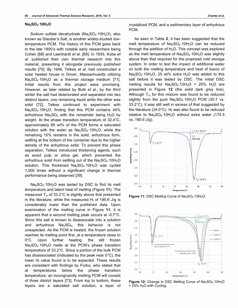
Na2SO4·10H2O was tested by DSC to find its melt temperature and latent heat of melting (Figure 11). The measured Tm of 33.2°C is slightly above that presented in the literature, while the measured Hf of 190.6 J/g is considerably lower than the published data. Upon examination of the melting curve in Figure 11, it is apparent that a second melting peak occurs at -0.7°C. Since this salt is known to disassociate into a solution and anhydrous Na2SO4, this behavior is not unexpected. As the PCM is heated, the frozen solution reaches its melting point first, at a temperature close to 0°C. Upon further heating, the still frozen Na2SO4·10H2O melts at the PCM’s phase transition temperature of 33.2°C. Since a portion of the bulk PCM has disassociated (indicated by the peak near 0°C), the lower Hf value found is to be expected. These results are consistent with findings by Furbo, who stated that at temperatures below the phase transition temperature, an incongruently melting PCM will consist of three district layers [73]. From top to bottom, these layers are a saturated salt solution, a layer of
crystalized PCM, and a sedimentary layer of anhydrous PCM.
As seen in Table 2, it has been suggested that the melt temperature of Na2SO4·10H2O can be reduced through the addition of H2O. This concept was explored as the melt temperature of Na2SO4·10H2O was slightly above than that required for the proposed cold storage system. In order to test the impact of additional water on both the melting temperature and heat of fusion of Na2SO4·10H2O, 25 wt% extra H2O was added to this salt before it was tested by DSC. The initial DSC melting results for Na2SO4·10H2O + 25% H2O are presented in Figure 12 (the solid dark grey line). Although Tm for this mixture was found to be reduced slightly from the pure Na2SO4·10H2O PCM (30.7 vs. 33.2°C), it was still well in excess of that suggested by the literature (24.0°C). Hf was also found to be reduced relative to Na2SO4·10H2O without extra water (174.5 vs. 190.6 J/g).
Figure 11: DSC Melting Curve of Na2SO4·10H2O.
Figure 12: Change in DSC Melting Curve of Na2SO4·10H2O + 25% H2O with Cycling.

Experimental Characterization of Low-Temperature Inorganic Journal of Advanced Thermal Science Research, 2019, Vol. 6 81
The DSC melting curves of Figure 12 show a similar trend to that for pure Na2SO4·10H2O in Figure 11, where a peak forms around 0°C and at the tetrahydrate’s melting temperature. For the case with 25 wt% extra H2O in Figure 12, it can be seen that the peak at ~0°C is larger than that for Na2SO4·10H2O without extra water (see Figure 11). This indicates that the added extra water is preferentially entrained in the salt solution rather than forming a stable compound with the Na2SO4·10H2O.
In order to test the stability of Na2SO4·10H2O + 25% H2O with cycling, the DSC sample was subjected to three thermal cycles. Heat flow traces for the melting portions of these three cycles are seen in Figure 12. These results qualitatively show that the peak at the tetrahydrate melt temperature (~35°C) decreases in height with increasing cycles, while the peak at ~0°C simultaneously increases in height. This behavior is a clear indication of phase separation within this salt brought about through thermal cycling. Given the large magnitude of this change in peak height with a very small number of cycles, it is suggested that Na2SO4·10H2O + 25% H2O is extremely unstable with cycling and measures must be taken to prevent this separation if this PCM is to have any commercial utility.
CONCLUSIONS
Differential scanning calorimetry (DSC) has been demonstrated as an effective technique for analyzing both the melt temperature (Tm) and latent heat of fusion (Hf) of low-temperature phase change materials. While DSC was found to be capable of measuring the thermal properties of a PCM during melting, it was found that supercooling prevents accurate DSC analysis during freezing. This limitation arises from both the small DSC sample size and relatively high cooling rate (7°C/min) of the DSC.
Two CaCl2·6H2O-based eutectics were found, which have favorable thermal properties in the 20-30°C phase transition temperature range. The first, CaCl2·6H2O + KNO3 was found to have a tunable melt temperature based on the quantity of KNO3 added. PCM melt temperature was found to vary significantly as the weight percentage of KNO3 was varied between 0% (28.3°C) and 10.8% (15.3°C). When a mixture of 7 wt% KNO3 was selected for closer analysis, a Tm of 19.6°C and Hf of 120 J/g were found using DSC testing. A second eutectic mixture of CaCl2·6H2O + 18 wt% MgCl2·6H2O was found through experimentation and supported through phase diagram modeling. DSC
testing of this eutectic found it to melt at 21.9°C with an Hf of 149 J/g.
DSC testing of Glauber’s salt revealed significant phase separation for this material. Phase separation of this salt was evident by the appearance of two distinct phase transition heat flux peaks before any cycling was undertaken. One peak corresponds to the melt point of the Na2SO4·10H2O, while the other occurs at the melting point of a water/salt solution. When this PCM was cycled three times in the DSC, the peak corresponding to the Na2SO4·10H2O melt temperature was found to decrease in size with a corresponding increase in size of the water/salt solution peak.
ACKNOWLEDGMENTS
The information, data, or work presented herein was funded in part by the Advanced Research Projects Agency – Energy (ARPA-E), U.S. Department of Energy.
The information, data, or work presented herein was funded in part by an agency of the United States Government. Neither the United States Government nor any agency thereof, nor any of their employees, makes any warranty, express or implied, or assumes any legal liability or responsibility for the accuracy, completeness, or usefulness of any information, apparatus, product, or process disclosed, or represents that its use would not infringe privately owned rights. Reference herein to any specific commercial product, process, or service by trade name, trademark, manufacturer, or otherwise does not necessarily constitute or imply its endorsement, recommendation, or favoring by the United States Government or any agency thereof. The views and opinions of authors expressed herein do not necessarily state or reflect those of the United States Government or any agency thereof.
REFERENCES
[1] Telkes, M. Thermal Energy Storage in Salt Hydrates. Solar Energy Materials, 2, 1980, 381-393. https://doi.org/10.1016/0165-1633(80)90033-7
[2] Lane, G. (ed.) Solar Heat Storage: Latent Heat Materials, Volume I: Background and Scientific Principles. CRC Press, Boca Raton, FL, 1983. https://doi.org/10.1115/1.3266412
[3] Lane, G. Low Temperature Heat Storage with Phase Change Materials. The International Journal of Ambient Energy, 1(3), 1980, 155-168. https://doi.org/10.1080/01430750.1980.9675731
[4] Carlsson, B., Stymne, H., Wettermark, G. An Incongruent Heat-of-Fusion System-CaCl2·6H2O-Made Congruent

82 Journal of Advanced Thermal Science Research, 2019, Vol. 6 Charles et al.
Through Modification of the Chemical Composition of the System. Solar Energy, 23, 1979, 343-350. https://doi.org/10.1016/0038-092X(79)90129-4
[5] Abhat, A. Low Temperature Latent Heat Thermal Energy Storage: Heat Storage Materials. Solar Energy, 30(4), 1983, 313-332. https://doi.org/10.1016/0038-092X(83)90186-X
[6] Kimura, H. Impurity Effect on Growth Rates of CaCl2·6H2O Crystals. Journal of Crystal Growth, 73, 1985, 53-62. https://doi.org/10.1016/0022-0248(85)90330-6
[7] Kimura, H., Kai, J. Mixtures of Calcium Chloride Hexahydrate with Some Salt Hydrates or Anhydrous Salts as Latent Heat Storage Materials. Energy Conversion and Management, 28(3), 1988, 197-200. https://doi.org/10.1016/0196-8904(88)90021-0
[8] Kimura, H., Kai, J. Phase Change Stability of CaCl2·6H2O. Solar Energy, 33(6), 1984, 557-563. https://doi.org/10.1016/0038-092X(84)90011-2
[9] N’Tsoukpoe, K., Rammelberg, H., Lele, A., Korhammer, K., Watts, B., Schmidt, T., Ruck, W. A Review on the Use of Calcium Chloride in Applied Thermal Engineering. Applied Thermal Engineering, 75, 2015, 513-531. https://doi.org/10.1016/j.applthermaleng.2014.09.047
[10] N’Tsoukpoe, D., Schmidt, T., Rammelberg, H., Watts, B., Ruck, W. A Systematic Multi-Step Screening of Numerous Salt Hydrates for Low Temperature Thermochemical Energy Storage. Applied Energy, 124, 2014, 1-16. https://doi.org/10.1016/j.apenergy.2014.02.053
[11] Tyagi, V., Kaushik, S., Pandey, A., Tyagi, S. Experimental Study of Supercooling and pH Behaviour of a Typical Phase Change Material for Thermal Energy Storage. Indian Journal of Pure & Applied Physics, 49, 2011, 117-125.
[12] Tyagi, V., Buddhi, D. PCM Thermal Storage in Buildings: A State of Art. Renewable and Sustainable Energy Reviews, 11, 2007, 1147-1166. https://doi.org/10.1016/j.rser.2005.10.002
[13] Carlsson, B. Phase Change Behaviour of Some Latent Heat Storage Media Based on Calcium Chloride Hexahydrate. Solar Energy, 83, 2009, 485-500. https://doi.org/10.1016/j.solener.2008.09.004
[14] Sharma, S., Kitano, H., & Sagara, K. Phase Change Materials for Low Temperature Solar Thermal Applications. Res. Rep. Fac. Eng. Mie Univ., 29, 2004, 31-64.
[15] Sharma, A., Tyagi, V., Chen, C., Buddhi, D. Review on Thermal Energy Storage with Phase Change Materials and Applications. Renewable and Sustainable Energy Reviews, 13, 2009, 318-345. https://doi.org/10.1016/j.rser.2007.10.005
[16] Sharma, A. Chen, C. Solar Water Heating System with Phase Change Materials. International Review of Chemical Engineering, 1(4), 2009, 297-307.
[17] Oró, E., de Gracia, A., Castell, A., Farid, M., Cabeza, L. Review on Phase Change Materials (PCMs) for Cold Thermal Energy Storage Applications. Applied Energy, 99, 2012, 513-533. https://doi.org/10.1016/j.apenergy.2012.03.058
[18] Cantor, S. Applications of Differential Scanning Calorimetry to the Study of Thermal Energy Storage. Thermochimica Acta, 26(1), 1978, 39-47. https://doi.org/10.1016/0040-6031(78)80055-0
[19] Cantor, S. DSC Study of Melting and Solidification of Salt Hydrates. Thermochimica Acta, 33, 1979, 69-86. https://doi.org/10.1016/0040-6031(79)87030-6
[20] Bhatt, V., Gohil, K., Mishra, A. Thermal Energy Storage Capacity of Some Phase Changing Materials and Ionic Liquids. International Journal of ChemTech Research, 2(3), 2010, 1771-1779.
[21] Cabeza, L., Castell, A., Barreneche, C., de Gracia, A., Fernández, A. Materials Used as PCM in Thermal Energy Storage in Buildings: A Review. Renewable and Sustainable Energy Reviews, 15, 2011, 1675-1695. https://doi.org/10.1016/j.rser.2010.11.018
[22] Naumann, R., Emons, H. Results of Thermal Analysis for Investigation of Salt Hydrates as Latent Heat-Storage Materials. Journal of Thermal Analysis, 35, 1989, 1009-1031. https://doi.org/10.1007/BF02057256
[23] Siemens, P., Giauque, W. The Entropies of the Hydrates of Sodium Hydroxide. II. Low-Temperature Heat Capacities and Heats of Fusion of NaOH·2H2O and NaOH·3.5H2O. The Journal of Physical Chemistry, 73(1), 1969, 149-157. https://doi.org/10.1021/j100721a024
[24] Zalba, B., Marín, J. M., Cabeza, L. F., & Mehling, H. Review on Thermal Energy Storage with Phase Change - Materials Heat Transfer Analysis and Applications. Applied Thermal Engineering, 23, 2003, 251-283. https://doi.org/10.1016/S1359-4311(02)00192-8
[25] Heckenkamp, J., Baumann, H. Latentwärmespeicher (Latent Heat Storage Systems). Nachrichten aus Chemie, Technik und Laboratorium / Herausgegeben von der Gesellschaft Deutscher Chemiker, 45(11), 1997, 1075-1081. https://doi.org/10.1002/nadc.199700023
[26] Shamberger, P., Reid, T. Thermophysical Properties of Potassium Fluoride Tetrahydrate from (243 to 348) K. Journal of Chemical & Engineering Data, 58, 2013, 294-300. https://doi.org/10.1021/je300854w
[27] Socaciu, L. Thermal Energy Storage with Phase Change Material. Leonardo Electronic Journal of Practices and Technologies, (20), 2012, 75-98.
[28] Kenisarin, M. Short-Term Storage of Solar Energy. 1. Low Temperature Phase-Change Materials. Applied Solar Energy, 29(2), 1993, 48-65.
[29] Climator. Phase Change Materials. <https://beopt.nrel.gov/ sites/beopt.nrel.gov/files/ Harvard%20Group07.Phase ChangeMaterials.pdf> Accessed: Sept. 2015.
[30] Demirbas, M., Thermal Energy Storage and Phase Change Materials: An Overview. Energy Sources, Part B: Economics, Planning, and Policy. 1(1), 2006, 85-95. https://doi.org/10.1080/009083190881481
[31] Jeon, J., Jungki, S., Jeong, S., Kim, S. PCM Application Methods for Residential Building Using Radiant Floor Heating Systems. Building Environment & Materials Lab, School of Architecture, Soongsil University, Seoul, Korea.
[32] Nagano, K., Mochida, T., Takeda, S., Domański, R., & Rebow, M. Thermal Characteristics of Manganese (II) Nitrate Hexahydrate as a Phase Change Material for Cooling Systems. Applied Thermal Engineering, 23, 2003, 229-241. https://doi.org/10.1016/S1359-4311(02)00161-8
[33] Garg, H., Mullick, S., Bhargava, A. Solar Thermal Energy Storage. D. Reidel Publishing Company, Dordrecht, Holland. 1985. https://doi.org/10.1007/978-94-009-5301-7
[34] Esen, M, Durmuş, A., Durmuş, A. Geometric Design of Solar-Aided Latent Heat Store Depending on Various Parameters and Phase Change Materials. Solar Energy, 62(1), 1998, 19-28. https://doi.org/10.1016/S0038-092X(97)00104-7
[35] Feilchenfeld, H., Fuchs, J., Kahana, F., Sarig, S. The Melting Point Adjustment of Calcium Chloride Hexahydrate by Addition of Potassium Chloride or Calcium Bromide Hexahydrate. Solar Energy, 34(2), 1985, 199-201. https://doi.org/10.1016/0038-092X(85)90181-1
[36] Hale, D., Hoover, M., O’Neill, M. Phase Change Materials Handbook. Technical Report. Huntsville (AL): National Aeronautics and Space Administration; 1971 September. Report no.: NASA-CR-61363. Contract no.: NAS8-25183. http://dx.doi.org/2060/19720012306

Experimental Characterization of Low-Temperature Inorganic Journal of Advanced Thermal Science Research, 2019, Vol. 6 83
[37] Leenhardt & Boutaric. Cryoscopie Dans les Sels Hydratés Fondus. Bulletin de la Société Chimique de France, 13, 1913, 651-657.
[38] Lorsch, H., Kauffman, K., Denton, J. Thermal Energy Storage for Solar Heating and Off-Peak Air Conditioning. Energy Conversion, 17, 1975, 1-8. https://doi.org/10.1016/0013-7480(75)90002-9
[39] Telkes, M. Thermal Storage for Solar Heating and Cooling. Proceedings of the Workshop on Solar Energy Storage Subsystems for the Heating and Cooling of Buildings, Charlottesville, VA, 1975, 17-23.
[40] Shamberger, P., Reid, T. Thermophysical Properties of Lithium Nitrate Trihydrate from (253 to 353) K. Journal of Chemical & Engineering Data, 57, 2012, 1404-1411. https://doi.org/10.1021/je3000469
[41] Costello, V., Melsheimer, S., Edie, D. Heat Transfer and Calorimetric Studies of a Direct Contact-Latent Heat Energy Storage System. Proceedings of the Winter Annual Meeting of the American Society of Mechanical Engineers, San Francisco, CA, December 10-15, 1978.
[42] Gawron, K., Schröder, J. Properties of Some Salt Hydrates for Latent Heat Storage. Energy Research, 1, 1977, 351-363. https://doi.org/10.1002/er.4440010407
[43] Ghoneim, A. Comparison of Theoretical Models of Phase-Change and Sensible Heat Storage for Air and Water-Based Solar Heating Systems. Solar Energy, 42(3), 1989, 209-220. https://doi.org/10.1016/0038-092X(89)90013-3
[44] Kobe, K., Anderson, C. The Heat Capacity of Saturated Sodium Sulfate Solution. The Journal of Physical Chemistry, 40(4), 1936, 429-433. https://doi.org/10.1021/j150373a001
[45] Pitzer, K., Coulter, L. The Heat Capacities, Entropies, and Heats of Solution of Anhydrous Sodium Sulfate and of Sodium Sulfate Decahydrate. The Application of the Third Law of Thermodynamics to Hydrated Crystals. Journal of the American Chemical Society, 60, 1938, 1310-1313. https://doi.org/10.1021/ja01273a010
[46] Salunkhe, P., Krishna, D. Investigations of Latent Heat Storage Materials for Solar Water and Space Heating Applications. Journal of Energy Storage, 12, 2017, 243-260. https://doi.org/10.1016/j.est.2017.05.008
[47] Telkes, M. Nucleation of Supersaturated Inorganic Salt Solutions. Industrial and Engineering Chemistry, 1952, 1308-1310. https://doi.org/10.1021/ie50510a036
[48] Kenisarin, M., Mahkamov, K. Solar energy storage using phase change materials. Renewable and Sustainable Energy Reviews, 11(9), 2007, 1913-1965. https://doi.org/10.1016/j.rser.2006.05.005
[49] Dow Chemical Company. Calcium Chloride Handbook: A Guide to Properties, Forms, Storage and Handling. Dow Chemical Company, 2003.
[50] Zhang, Y., Zhou, G., Lin, K., Zhang, Q., Di, H. Application of Latent Heat Thermal Energy Storage in Buildings: State-of-the-Art and Outlook. Building and Environment, 42(6), 2007, 2197-2209. https://doi.org/10.1016/j.buildenv.2006.07.023
[51] Gao, D., Deng, T. Energy Storage - Preparations and Physiochemical Properties of Solid-Liquid Phase Change Materials for Thermal Energy Storage. Materials and Processes for Energy: Communicating Current Research and Technological Developments. Formatex., 2013, 32-44.
[52] Linnow, K., Niermann, M., Bonatz, D., Posern, K., Steiger, M. Experimental Studies of the Mechanism and Kinetics of Hydration Reactions. Energy Procedia, 48, 2014, 394-404. https://doi.org/10.1016/j.egypro.2014.02.046
[53] Lane, G., Rossow, H. Reversible Phase Change Compositions of Calcium Chloride Hexahydrate with
Potassium Chloride. U.S. Patent US 4613444 A, 1986 [cited December 6, 2016], Available from: <www.google.com/patents/US4613444>.
[54] ThermoFisher Scientific. Potassium Fluoride Safety Data Sheet. Rev. May, 2018. Available from: <https://www. fishersci.com/store/msds?partNumber=AC390810250&productDesc ription=POTASSIUM+FLUORIDE%2C+40+W+ 25GR&vendorId=VN00032119&countryCode=US&language=en> Accessed: Oct. 12, 2018.
[55] 王维, 张慧洁, 张哲明, 陈海滨, 吴景深. Phase Change Material and Preparation Method. Chinese Patent CN 104419381 A, 2015 [cited Aug. 9, 2018] (Translated from Chinese), Available from: <https://patents.google.com/ patent/CN104419381A/en?oq=CN104419 381A>.
[56] Thomsen, K. Phase Diagram Software. Aqueous Solutions Aps., Denmark. Available from: <http://www.phasediagram. dk>.
[57] Thomsen, K., Iliuta, M., Rasmussen, P. Extended UNIQUAC Model for Correlation and Prediction of Vapor-Liquid-Liquid-Solid Equilibria in Aqueous Salt Systems Containing Non-Electrolytes. Part B. Alcohol (Ethanol, Propanols, Butanols)-Water-Salt Systems. Chemical Engineering Science, 59, 2004, 3631-3647. https://doi.org/10.1016/j.ces.2004.05.024
[58] Iliuta, M., Thomsen, K., Rasmussen, P. Extended UNIQUAC Model for Correlation and Prediction of Vapour-Liquid-Solid Equilibria in Aqueous Salt Systems Containing Non-Electrolytes. Part A. Methanol-Water-Salt Systems. Chemical Engineering Science, 55, 2000, 2673-2686. https://doi.org/10.1016/S0009-2509(99)00534-5
[59] Roozeboom, H. Experimentelle und Theoretische Studien über die Gleichgewichtsbedingungen Zwischen Festen und Flüssigen Verbinungen von Wasser min Salzen, Besonders mit dem Chlorcalcium. Zeitschrift f. Physik. Chemie. 4, 1889, 31-65. https://doi.org/10.1515/zpch-1889-0105
[60] Feilchenfeld, H., Fuchs, J., Sarig, S. A Calorimetric Investigation of the Stability of Stagnant Calcium Chloride Hexahydrate Melt. Solar Energy, 32(6), 1984, 779-784. https://doi.org/10.1016/0038-092X(84)90252-4
[61] Feilchenfeld, H., Sarig, S. Calcium Chloride Hexahydrate: A Phase-Changing Material for Energy Storage. Industrial & Engineering Chemistry Product Research and Development, 24(1), 2985, 130-133. https://doi.org/10.1021/i300017a024
[62] Brandstetter, A. On the Stability of Calcium Chloride Hexahydrate in Thermal Storage Systems. Solar Energy, 41(2), 1988, 183-191. https://doi.org/10.1016/0038-092X(88)90135-1
[63] Lane, G. Adding Strontium Chloride or Calcium Hydroxide to Calcium Chloride Hexahydrate Heat Storage Material. Solar Energy, 27, 1981, 73-75. https://doi.org/10.1016/0038-092X(81)90023-2
[64] Lane, G. (ed.) Solar Heat Storage: Latent Heat Materials, Volume II: Technology. CRC Press, Boca Raton, FL. 1986.
[65] Shahbaz, K., AlNashef, I., Lin, R., Hashim, M., Mjalli, F., Farid, M. A Novel Calcium Chloride Hexahydrate-Based Deep Eutectic Solvent as a Phase Change Materials. Solar Energy Materials & Solar Cells, 155, 2016, 147-154. https://doi.org/10.1016/j.solmat.2016.06.004
[66] Yuan, K., Zhou, Y., Sun, W., Fang, X., Zhang, Z. A Polymer-Coated Calcium Chloride Hexahydrate/Expanded Graphite Composite Phase Change Material with Enhanced Thermal Reliability and Good Applicability. Composites Science and Technology, 156, 2018, 78-86. https://doi.org/10.1016/j.compscitech.2017.12.021
[67] Li, X., Zhou, Y., Nian, H., Zhang, Z., Dong, O., Ren, X., Zeng, J., Hai, C., Shen, Y. Advanced Nanocomposite Phase Change Material Based on Calcium Chloride Hexahydrate

84 Journal of Advanced Thermal Science Research, 2019, Vol. 6 Charles et al.
with Aluminum Oxide Nanoparticles for Thermal Energy Storage. Energy & Fuels, 31, 2017, 6560-6567. https://doi.org/10.1021/acs.energyfuels.7b00851
[68] Cohen, E. Die Bestimmung von Umwandlungspunkten auf Elektrischem Wege und die Elektromotorische Kraft bei Chemischer Zersetzung. Zeitshrift für Physikalische Chemie, 14, 1894, 53-92. https://doi.org/10.1515/zpch-1894-1403
[69] Leenhardt & Boutaric. Cryoscopie Dans les Sels Hydratés Fondus. Bulletin de la Société Chimique de France, 13, 1913, 651-657.
[70] Kobe, K., Anderson, C. The Heat Capacity of Saturated Sodium Sulfate Solution. The Journal of Physical Chemistry, 40(4), 1936, 429-433. https://doi.org/10.1021/j150373a001
[71] Telkes, M., Raymond, R. Storing Solar Heat in Chemicals – A Report on the Dover House. Heating and Ventilating, 46, 1949, 80-86.
[72] Butti, K., Perlin, J. A Golden Thread – 2500 Years of Solar Architecture and Technology. Cheshire Books, Palo Alto, CA. 1980.
[73] Furbo, S. Heat Storage Units Using a Salt Hydrate as Storage Medium Based on the Extra Water Principle. Report EUR 8169 EN, Commission of the European Communities, Luxembourg, 1983.
Received on 06-07-2019 Accepted on 19-11-2019 Published on 30-12-2019
DOI: http://dx.doi.org/10.15377/2409-5826.2019.06.8
© 2019 Charles et al.; Avanti Publishers. This is an open access article licensed under the terms of the Creative Commons Attribution Non-Commercial License (http://creativecommons.org/licenses/by-nc/3.0/) which permits unrestricted, non-commercial use, distribution and reproduction in any medium, provided the work is properly cited.


![CONTENIDO - r6 1.1cc/1.3cc (71/84) buje tensor direcciÓn [zanahoria] ref: 7700500113 cod: 31204 - r6 1.1cc/1.3cc (71/84) buje contera direcciÓn ref: 7700509247 cod: 31205 - r6 1.1cc/1.3cc](https://img.pdfslide.net/doc/110x75/612d23c61ecc5158694200fb/contenido-r6-11cc13cc-7184-buje-tensor-direccin-zanahoria-ref-7700500113.jpg)