Embed Size (px)
Citation preview
Journal of Environmental Chemical Engineering 3 (2015) 2104–2114
Energy and exergy analysis of chemical looping combustion technologyand comparison with pre-combustion and oxy-fuel combustiontechnologies for CO2 capture
Sanjay Mukherjeea, Prashant Kumara,*, Aidong Yangb, Paul Fennellc
aDepartment of Civil and Environmental Engineering, University of Surrey, Guildford, Surrey GU2 7XH, United KingdombDepartment of Engineering Science, University of Oxford, Parks Road, Oxford OX1 3PJ, United KingdomcDepartment of Chemical Engineering, Imperial College London, South Kensington, London SW7 2AZ, United Kingdom
A R T I C L E I N F O
Article history:Received 27 April 2015Received in revised form 1 July 2015Accepted 22 July 2015Available online 26 July 2015
Keywords:Coal power plantsCO2 captureChemical looping combustionExergy analysis
A B S T R A C T
Carbon dioxide (CO2) emitted from conventional coal-based power plants is a growing concern for theenvironment. Chemical looping combustion (CLC), pre-combustion and oxy-fuel combustion arepromising CO2 capture technologies which allow clean electricity generation from coal in an integratedgasification combined cycle (IGCC) power plant. This work compares the characteristics of the abovethree capture technologies to those of a conventional IGCC plant without CO2 capture. CLC technology isalso investigated for two different process configurations—(i) an integrated gasification combined cyclecoupled with chemical looping combustion (IGCC–CLC), and (ii) coal direct chemical looping combustion(CDCLC)—using exergy analysis to exploit the complete potential of CLC. Power output, net electricalefficiency and CO2 capture efficiency are the key parameters investigated for the assessment. Flowsheetmodels of five different types of IGCC power plants, (four with and one without CO2 capture), weredeveloped in the Aspen plus simulation package. The results indicate that with respect to conventionalIGCC power plant, IGCC–CLC exhibited an energy penalty of 4.5%, compared with 7.1% and 9.1% for pre-combustion and oxy-fuel combustion technologies, respectively. IGCC–CLC and oxy-fuel combustiontechnologies achieved an overall CO2 capture rate of �100% whereas pre-combustion technology couldcapture �94.8%. Modification of IGCC–CLC into CDCLC tends to increase the net electrical efficiency by4.7% while maintaining 100% CO2 capture rate. A detailed exergy analysis performed on the two CLCprocess configurations (IGCC–CLC and CDCLC) and conventional IGCC process demonstrates that CLCtechnology can be thermodynamically as efficient as a conventional IGCC process.ã 2015 The Authors. Published by Elsevier Ltd. This is an open access article under the CC BY license
(http://creativecommons.org/licenses/by/4.0/).
Contents lists available at ScienceDirect
Journal of Environmental Chemical Engineering
journal homepage: www.elsevier .com/ locate / je ce
Introduction
Combustion of carbonaceous fuels (mainly coal, which is cheapand widely available) to produce electricity in power plants emitsCO2, which causes climate change [1]. Coal will continue todominate power production in the near future due to its lower
Abbreviations: AGR, acid–gas removal; ASU, air separation unit; CDCLC, coaldirect chemical looping combustion; CLC, chemical looping combustion; DEA,diethanolamine; GT, gas turbine; HP, high pressure; HRSG, heat recovery steamgenerator; IEA, international energy agency; IGCC, integrated gasification combinedcycle; IGCC–CLC, integrated gasification combined cycle with chemical loopingcombustion; IP, intermediate pressure; LP, low pressure; MDEA, methyl dietha-nolamine; MEA, monoethanolamine; MW, megawatt; OC, oxygen carrier; PC,pulverised coal; ST, steam turbine; WGS, water–gas shift.* Corresponding author. Tel.: +44 1483 682762; fax: +44 1483 682135.E-mail addresses: [email protected], [email protected]
(P. Kumar).
http://dx.doi.org/10.1016/j.jece.2015.07.0182213-3437/ã 2015 The Authors. Published by Elsevier Ltd. This is an open access artic
price and 113 years of reserves globally [2,3], although it is highlypolluting [4]. Therefore, developing clean and cheap energy fromcoal has been an issue of international concern and a challenge forengineers and researchers [5]. Substantial efforts are being madeworldwide to find new technologies to use coal in an environmen-tally-friendly manner [6–9].
Integrated gasification combined cycle coupled with chemicallooping combustion (IGCC–CLC) and direct coal chemical loopingcombustion (CDCLC) are promising technologies to produce cleanelectricity from coal by efficiently incorporating CO2 capture [10–14]. Chemical looping combustion (CLC) systems consist of twointerconnected fluidised bed reactors which separately effect theoxidation and reduction reactions of an oxygen carrier (OC) [15,16].The OC particles are continuously circulated to supply oxygen forcombustion of solid or gaseous fuel(s). This arrangement preventsdilution of products of combustion (steam and CO2) with nitrogen(N2). Steam is condensed out, to obtain a pure stream of CO2 for
le under the CC BY license (http://creativecommons.org/licenses/by/4.0/).
S. Mukherjee et al. / Journal of Environmental Chemical Engineering 3 (2015) 2104–2114 2105
transport and storage. Cormos [11] and Erlach et al. [12] presenteda detailed plant concept and methodology for an IGCC–CLC processwhich would exhibit a net electrical efficiency of 39% and a CO2
capture rate of �100%. Cormos and Cormos [10] evaluatedthoroughly plant configuration and operational aspects for CDCLCprocesses. Their study showed that CDCLC can achieve a netelectrical efficiency of 42.01% with a 99.81% CO2 capture rate.
Physical absorption-based pre-combustion capture, and cap-ture following oxy-fuel combustion, are another two promisingtechnologies for CO2 capture, which are commonly studied [17–20]. Oxy-fuel combustion involves burning the fuel in a mixture ofpure oxygen and recycled CO2 (the CO2 serves as thermal ballast, toreduce the overall flame temperature, which would be exceedinglyhigh for a mixture of pure oxygen and fuel). Pre-combustioncapture includes the gasification of the fuel, which involvesreaction with oxygen in sub-stoichiometric quantities to produce amixture of carbon monoxide (CO), CO2, methane (CH4), hydrogen(H2) and steam/vapour (H2O). The CH4 from the gasification issubsequently reformed in the presence of steam to a mixture of COand H2, and finally the CO undergoes the water–gas shift reactionwith H2O to produce a mixture of CO2 and H2, with the CO2 beingremoved and the H2 then burned in a modified gas turbine or usedto power a fuel cell (after significant clean-up). Chiesa et al. [18]investigated physical absorption-based (Selexol solvent) pre-combustion capture for an IGCC plant producing 390–425 MWelectricity. They observed a net electrical efficiency between 36and 39% with �91% CO2 capture rate and a 6.1–7.5% efficiencypenalty against reference cases without CO2 capture. Padureanet al. [60] compared different types of physical (Selexol, Rectisol,Purisol) and chemical (MDEA) solvents by applying physicalabsorption-based pre-combustion capture technologies to a base-case IGCC plant with 425–450 MW power output. They concludedthat the IGCC process using Selexol is the most efficient capturetechnology, with a net electrical output of 36.08% and a CO2
capture rate of 91.43%. A collaborative project between VattenfallGroup, Energy Research Centre of the Netherlands and DelftUniversity of Technology has successfully developed and validatedmethodology and tool for retrofitting a Selexol based pre-combustion capture method for an IGCC plant at Groningen,Netherlands [21].
Studies on oxy-fuel combustion are mainly restricted topulverised coal (PC) power plants. However, some studies haveproposed new process designs to incorporate oxy-fuel combustioninto IGCC plants. For instance, Oki et al. [20] demonstrated aninnovative oxy-fuel IGCC process using pure oxygen instead of airin the gas turbine (GT) combustor unit of an IGCC. Thisconfiguration prevents dilution of the GT exhaust stream withN2 and produces a pure CO2 stream. Experimental apparatusconstructed for their new oxy-fuel IGCC process was used to testthe performance of different types of fuels (coal and biomass) forpower generation. Kunze and Spliethoff [19] have also proposed anadvanced process design, using combination IGCC and oxy-fuelcombustion technologies that purports a net electrical efficiency of45.74% and is capable of capturing 96–99% CO2. Supplementaryinformation (SI) Table S1 shows a comparison of different CO2
capture technologies through published literature.
Table 1Description of different cases used in our study.
Case no. CO2 capture technology used
1 Conventional IGCC
2 IGCC with physical absorption bas3 IGCC with oxy-fuel combustion
4 IGCC–CLC
5 CDCLC
Existing work discussing individual capture technologies isdifficult to use for direct comparison due to variation in modellingassumptions such as type of fuel used, scale of power output andefficiencies of individual process units. Furthermore, there is nostudy available to our knowledge, which provides a comparisonbetween CLC and oxy-fuel combustion technologies for IGCCpower plants. In this work, we compared IGCC–CLC, CDCLC, pre-combustion and oxy-fuel combustion technologies throughsimulation studies using common modelling assumptions andconsiderations. A detailed comparison with the conventional post-combustion technology was not included in this work. Interestedreaders are directed to publications such asKunze and Spliethoff[19] for a comparison between this and other technologies. Theabove four capture technologies were analysed against a conven-tional IGCC process without capture in order to estimate theenergy penalty associated with CO2 capture. An exergy analysiswas also performed for IGCC–CLC, CDCLC and conventional IGCCprocesses to understand the fuel conversion mechanism and tofind out the sources of irreversibilities in each process. Powerproduction, power consumption, electrical efficiency, CO2 captureefficiency and exergy are the key parameters studied in this work.
This work is solely based on the technical aspects of the CO2
capture technologies. A comparison of cost of electricity fordifferent capture technologies and commercial feasibility ofcarbon capture and storage will be considered in futurepublications. It should be also noted that the aim of this work isnot to produce a plant design better than those proposedpreviously. Instead, the focus is on producing a consistentcomparison between a numbers of technologies reported in theliterature.
Methodology
Flowsheet models of five large-scale IGCC processes with andwithout CO2 capture (see Table 1) were developed in Aspen plus inorder to investigate the effect of CO2 capture on net electricalefficiency and to allow comparisons of the capture technologies.The Aspen plus flowsheet models for the CO2 capture cases (Cases2–5) are provided in Supplementary information Fig. S1–S4. Anominal net power output between 400 and 500 MW was selectedfor all five cases. Table 2 shows the composition of Illinois #6 typecoal used as fuel in all five cases. A conventional IGCC plant withoutCO2 capture (Case 1) is considered as the base case. Cases 2 and 3represent IGCC processes with pre- and oxy-fuel combustion basedCO2 capture, respectively. Case 4 is IGCC–CLC process and Case 5 isthe CDCLC process with CO2 capture. A block diagram of Cases 2–5is shown in Figs. 1–4. Process configuration for Cases 2–5 isdiscussed in Section “Plant configuration”. Individual unit modelsused in the processes for existing technology, such as water–gasshift reactor, gasifier, GT, steam turbine (ST), heat exchangers, aremostly verified by supplier data described in [22,23]. Developmentof Aspen plus flowsheet models for all five cases is explained inSection “Developing an industrial level flowsheet model in Aspenplus’ while the methodology followed for exergy analysis isdescribed in Section “Exergy analysis”. Chemical and phaseequilibrium based on Gibbs free energy minimisation is utilised
CO2 capture
Noed pre-combustion capture Yes
YesYesYes
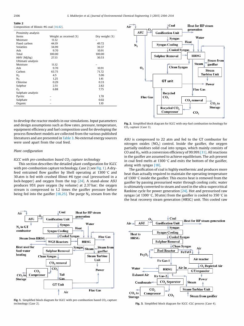
Table 2Composition of Illinois #6 coal [14,42].
Proximity analysisItems Weight as received (%) Dry weight (%)Moisture 11.12 –
Fixed carbon 44.19 49.72Volatiles 34.99 39.37Ash 9.70 10.91Total 100.00 100.00HHV (MJ/kg) 27.13 30.53Ultimate analysisMoisture 11.12 –
Ash 9.70 10.91Carbon 63.75 71.72H2 4.5 5.06N2 1.25 1.41Chlorine 0.29 0.33Sulphur 2.51 2.82O2 6.88 7.75Sulphate analysisPyritic – 1.70Sulphate – 0.02Organic – 1.10
Fig. 2. Simplified block diagram for IGCC with oxy-fuel combustion technology forCO2 capture (Case 3).
2106 S. Mukherjee et al. / Journal of Environmental Chemical Engineering 3 (2015) 2104–2114
to develop the reactor models in our simulations. Input parametersand design assumptions such as flow rates, pressure, temperature,equipment efficiency and fuel composition used for developing theprocess flowsheet models are collected from the various publishedliteratures and are presented in Table 3. No external energy sourceswere used apart from the coal feed.
Plant configuration
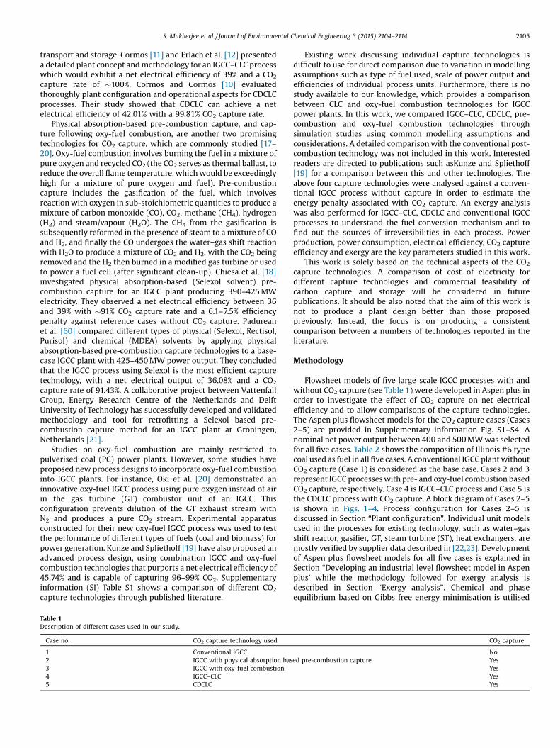
IGCC with pre-combustion based CO2 capture technologyThis section describes the detailed plant configuration for IGCC
with pre-combustion capture technology, Case 2 (see Fig. 1). A dry-feed entrained flow gasifier by Shell operating at 1300 �C and30 atm is fed with crushed Illinoi #6 type coal (pressurised in alock-hopper) and oxygen from the top [24]. A stand-alone ASUproduces 95% pure oxygen (by volume) at 2.37 bar; the oxygenstream is compressed to 1.2 times the gasifier pressure beforebeing fed into the gasifier [18,25]. The purge N2 stream from the
Fig. 1. Simplified block diagram for IGCC with pre-combustion based CO2 capturetechnology (Case 2).
ASU is compressed to 22 atm and fed to the GT combustor fornitrogen oxides (NOx) control. Inside the gasifier, the oxygenpartially oxidises solid coal into syngas, which mainly consists ofCO and H2, with a conversion efficiency of 99.99% [11]. All reactionsin the gasifier are assumed to achieve equilibrium. The ash presentin coal feed melts at 1300 �C and exits the bottom of the gasifier,along with syngas [18].
The gasification of coal is highly exothermic and produces moreheat than actually required to maintain the operating temperatureof 1300 �C inside the gasifier. This excess heat is removed from thegasifier by passing pressurised water through cooling coils; wateris ultimately converted to steam and used in the ultra-supercriticalRankine cycle for power generation [24]. Hot and pressurised rawsyngas (at 1300 �C, 30 atm) from the gasifier is cooled to 350 �C inthe heat recovery steam generation (HRSG) unit. This cooled raw
Fig. 3. Simplified block diagram for IGCC–CLC process (Case 4).
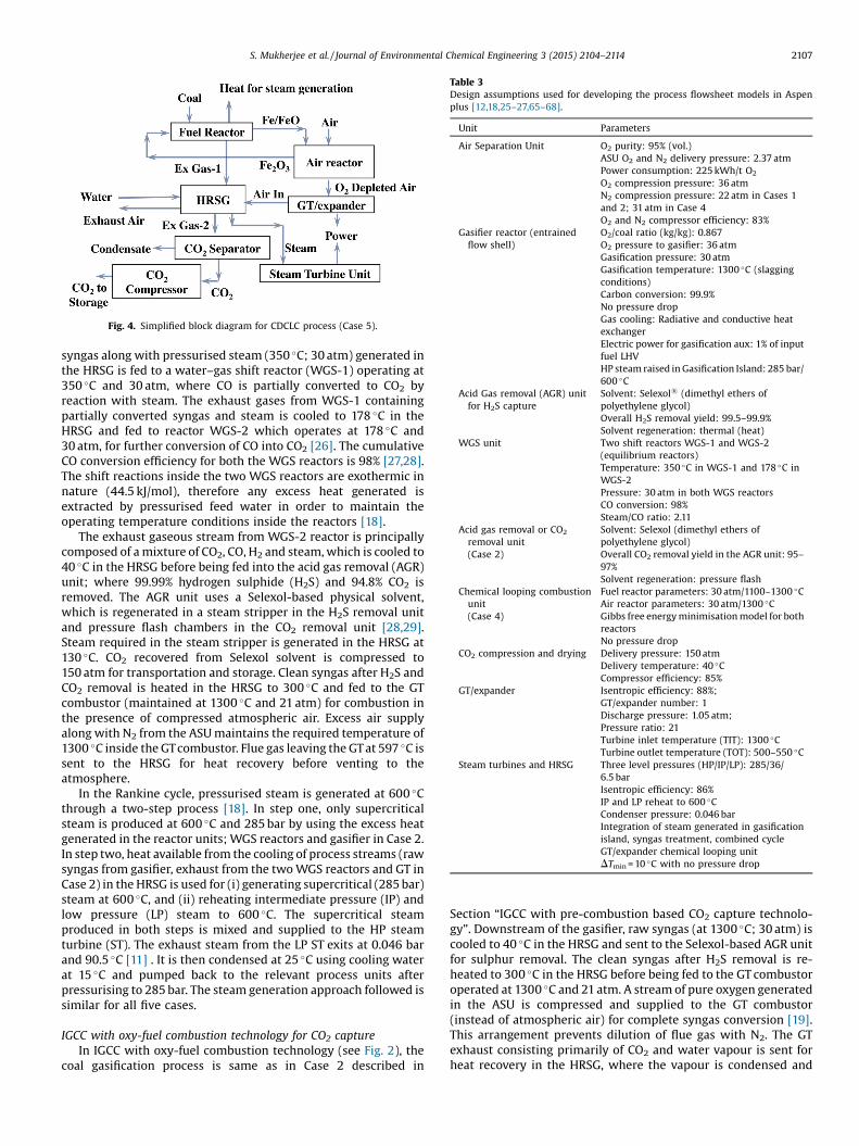
Fig. 4. Simplified block diagram for CDCLC process (Case 5).
Table 3Design assumptions used for developing the process flowsheet models in Aspenplus [12,18,25–27,65–68].
Unit Parameters
Air Separation Unit O2 purity: 95% (vol.)ASU O2 and N2 delivery pressure: 2.37 atmPower consumption: 225 kWh/t O2
O2 compression pressure: 36 atmN2 compression pressure: 22 atm in Cases 1and 2; 31 atm in Case 4O2 and N2 compressor efficiency: 83%
Gasifier reactor (entrainedflow shell)
O2/coal ratio (kg/kg): 0.867O2 pressure to gasifier: 36 atmGasification pressure: 30 atmGasification temperature: 1300 �C (slaggingconditions)Carbon conversion: 99.9%No pressure dropGas cooling: Radiative and conductive heatexchangerElectric power for gasification aux: 1% of inputfuel LHVHP steam raised in Gasification Island: 285 bar/600 �C
Acid Gas removal (AGR) unitfor H2S capture
Solvent: Selexol1 (dimethyl ethers ofpolyethylene glycol)Overall H2S removal yield: 99.5–99.9%Solvent regeneration: thermal (heat)
WGS unit Two shift reactors WGS-1 and WGS-2(equilibrium reactors)Temperature: 350 �C in WGS-1 and 178 �C inWGS-2Pressure: 30 atm in both WGS reactorsCO conversion: 98%Steam/CO ratio: 2.11
Acid gas removal or CO2
removal unit(Case 2)
Solvent: Selexol (dimethyl ethers ofpolyethylene glycol)Overall CO2 removal yield in the AGR unit: 95–97%Solvent regeneration: pressure flash
Chemical looping combustionunit(Case 4)
Fuel reactor parameters: 30 atm/1100–1300 �CAir reactor parameters: 30 atm/1300 �CGibbs free energy minimisation model for bothreactorsNo pressure drop
CO2 compression and drying Delivery pressure: 150 atmDelivery temperature: 40 �CCompressor efficiency: 85%
GT/expander Isentropic efficiency: 88%;GT/expander number: 1Discharge pressure: 1.05 atm;Pressure ratio: 21Turbine inlet temperature (TIT): 1300 �CTurbine outlet temperature (TOT): 500–550 �C
Steam turbines and HRSG Three level pressures (HP/IP/LP): 285/36/6.5 barIsentropic efficiency: 86%IP and LP reheat to 600 �CCondenser pressure: 0.046 barIntegration of steam generated in gasificationisland, syngas treatment, combined cycleGT/expander chemical looping unitDTmin = 10 �C with no pressure drop
S. Mukherjee et al. / Journal of Environmental Chemical Engineering 3 (2015) 2104–2114 2107
syngas along with pressurised steam (350 �C; 30 atm) generated inthe HRSG is fed to a water–gas shift reactor (WGS-1) operating at350 �C and 30 atm, where CO is partially converted to CO2 byreaction with steam. The exhaust gases from WGS-1 containingpartially converted syngas and steam is cooled to 178 �C in theHRSG and fed to reactor WGS-2 which operates at 178 �C and30 atm, for further conversion of CO into CO2 [26]. The cumulativeCO conversion efficiency for both the WGS reactors is 98% [27,28].The shift reactions inside the two WGS reactors are exothermic innature (44.5 kJ/mol), therefore any excess heat generated isextracted by pressurised feed water in order to maintain theoperating temperature conditions inside the reactors [18].
The exhaust gaseous stream from WGS-2 reactor is principallycomposed of a mixture of CO2, CO, H2 and steam, which is cooled to40 �C in the HRSG before being fed into the acid gas removal (AGR)unit; where 99.99% hydrogen sulphide (H2S) and 94.8% CO2 isremoved. The AGR unit uses a Selexol-based physical solvent,which is regenerated in a steam stripper in the H2S removal unitand pressure flash chambers in the CO2 removal unit [28,29].Steam required in the steam stripper is generated in the HRSG at130 �C. CO2 recovered from Selexol solvent is compressed to150 atm for transportation and storage. Clean syngas after H2S andCO2 removal is heated in the HRSG to 300 �C and fed to the GTcombustor (maintained at 1300 �C and 21 atm) for combustion inthe presence of compressed atmospheric air. Excess air supplyalong with N2 from the ASU maintains the required temperature of1300 �C inside the GT combustor. Flue gas leaving the GT at 597 �C issent to the HRSG for heat recovery before venting to theatmosphere.
In the Rankine cycle, pressurised steam is generated at 600 �Cthrough a two-step process [18]. In step one, only supercriticalsteam is produced at 600 �C and 285 bar by using the excess heatgenerated in the reactor units; WGS reactors and gasifier in Case 2.In step two, heat available from the cooling of process streams (rawsyngas from gasifier, exhaust from the two WGS reactors and GT inCase 2) in the HRSG is used for (i) generating supercritical (285 bar)steam at 600 �C, and (ii) reheating intermediate pressure (IP) andlow pressure (LP) steam to 600 �C. The supercritical steamproduced in both steps is mixed and supplied to the HP steamturbine (ST). The exhaust steam from the LP ST exits at 0.046 barand 90.5 �C [11] . It is then condensed at 25 �C using cooling waterat 15 �C and pumped back to the relevant process units afterpressurising to 285 bar. The steam generation approach followed issimilar for all five cases.
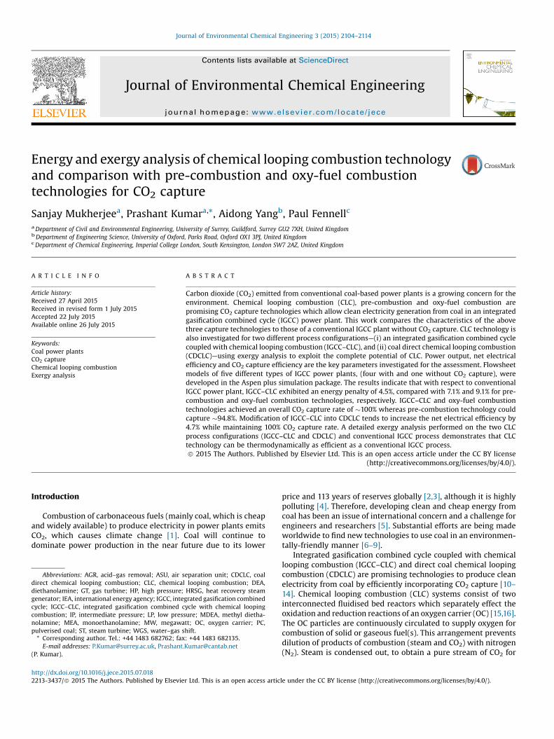
IGCC with oxy-fuel combustion technology for CO2 captureIn IGCC with oxy-fuel combustion technology (see Fig. 2), the
coal gasification process is same as in Case 2 described in
Section “IGCC with pre-combustion based CO2 capture technolo-gy”. Downstream of the gasifier, raw syngas (at 1300 �C; 30 atm) iscooled to 40 �C in the HRSG and sent to the Selexol-based AGR unitfor sulphur removal. The clean syngas after H2S removal is re-heated to 300 �C in the HRSG before being fed to the GT combustoroperated at 1300 �C and 21 atm. A stream of pure oxygen generatedin the ASU is compressed and supplied to the GT combustor(instead of atmospheric air) for complete syngas conversion [19].This arrangement prevents dilution of flue gas with N2. The GTexhaust consisting primarily of CO2 and water vapour is sent forheat recovery in the HRSG, where the vapour is condensed and
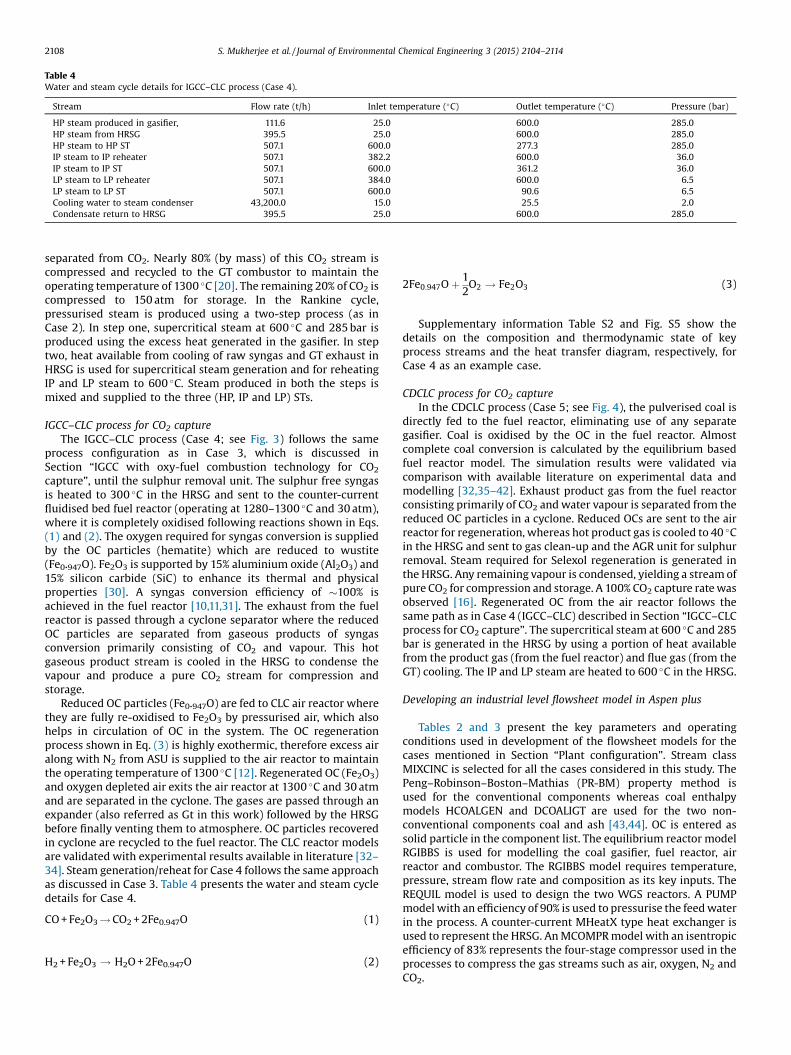
Table 4Water and steam cycle details for IGCC–CLC process (Case 4).
Stream Flow rate (t/h) Inlet temperature (�C) Outlet temperature (�C) Pressure (bar)
HP steam produced in gasifier, 111.6 25.0 600.0 285.0HP steam from HRSG 395.5 25.0 600.0 285.0HP steam to HP ST 507.1 600.0 277.3 285.0IP steam to IP reheater 507.1 382.2 600.0 36.0IP steam to IP ST 507.1 600.0 361.2 36.0LP steam to LP reheater 507.1 384.0 600.0 6.5LP steam to LP ST 507.1 600.0 90.6 6.5Cooling water to steam condenser 43,200.0 15.0 25.5 2.0Condensate return to HRSG 395.5 25.0 600.0 285.0
2108 S. Mukherjee et al. / Journal of Environmental Chemical Engineering 3 (2015) 2104–2114
separated from CO2. Nearly 80% (by mass) of this CO2 stream iscompressed and recycled to the GT combustor to maintain theoperating temperature of 1300 �C [20]. The remaining 20% of CO2 iscompressed to 150 atm for storage. In the Rankine cycle,pressurised steam is produced using a two-step process (as inCase 2). In step one, supercritical steam at 600 �C and 285 bar isproduced using the excess heat generated in the gasifier. In steptwo, heat available from cooling of raw syngas and GT exhaust inHRSG is used for supercritical steam generation and for reheatingIP and LP steam to 600 �C. Steam produced in both the steps ismixed and supplied to the three (HP, IP and LP) STs.
IGCC–CLC process for CO2 captureThe IGCC–CLC process (Case 4; see Fig. 3) follows the same
process configuration as in Case 3, which is discussed inSection “IGCC with oxy-fuel combustion technology for CO2
capture”, until the sulphur removal unit. The sulphur free syngasis heated to 300 �C in the HRSG and sent to the counter-currentfluidised bed fuel reactor (operating at 1280–1300 �C and 30 atm),where it is completely oxidised following reactions shown in Eqs.(1) and (2). The oxygen required for syngas conversion is suppliedby the OC particles (hematite) which are reduced to wustite(Fe0.947O). Fe2O3 is supported by 15% aluminium oxide (Al2O3) and15% silicon carbide (SiC) to enhance its thermal and physicalproperties [30]. A syngas conversion efficiency of �100% isachieved in the fuel reactor [10,11,31]. The exhaust from the fuelreactor is passed through a cyclone separator where the reducedOC particles are separated from gaseous products of syngasconversion primarily consisting of CO2 and vapour. This hotgaseous product stream is cooled in the HRSG to condense thevapour and produce a pure CO2 stream for compression andstorage.
Reduced OC particles (Fe0.947O) are fed to CLC air reactor wherethey are fully re-oxidised to Fe2O3 by pressurised air, which alsohelps in circulation of OC in the system. The OC regenerationprocess shown in Eq. (3) is highly exothermic, therefore excess airalong with N2 from ASU is supplied to the air reactor to maintainthe operating temperature of 1300 �C [12]. Regenerated OC (Fe2O3)and oxygen depleted air exits the air reactor at 1300 �C and 30 atmand are separated in the cyclone. The gases are passed through anexpander (also referred as Gt in this work) followed by the HRSGbefore finally venting them to atmosphere. OC particles recoveredin cyclone are recycled to the fuel reactor. The CLC reactor modelsare validated with experimental results available in literature [32–34]. Steam generation/reheat for Case 4 follows the same approachas discussed in Case 3. Table 4 presents the water and steam cycledetails for Case 4.
CO + Fe2O3! CO2 + 2Fe0.947O (1)
H2 + Fe2O3 ! H2O + 2Fe0.947O (2)
2Fe0:947O þ 12O2 ! Fe2O3 (3)
Supplementary information Table S2 and Fig. S5 show thedetails on the composition and thermodynamic state of keyprocess streams and the heat transfer diagram, respectively, forCase 4 as an example case.
CDCLC process for CO2 captureIn the CDCLC process (Case 5; see Fig. 4), the pulverised coal is
directly fed to the fuel reactor, eliminating use of any separategasifier. Coal is oxidised by the OC in the fuel reactor. Almostcomplete coal conversion is calculated by the equilibrium basedfuel reactor model. The simulation results were validated viacomparison with available literature on experimental data andmodelling [32,35–42]. Exhaust product gas from the fuel reactorconsisting primarily of CO2 and water vapour is separated from thereduced OC particles in a cyclone. Reduced OCs are sent to the airreactor for regeneration, whereas hot product gas is cooled to 40 �Cin the HRSG and sent to gas clean-up and the AGR unit for sulphurremoval. Steam required for Selexol regeneration is generated inthe HRSG. Any remaining vapour is condensed, yielding a stream ofpure CO2 for compression and storage. A 100% CO2 capture rate wasobserved [16]. Regenerated OC from the air reactor follows thesame path as in Case 4 (IGCC–CLC) described in Section “IGCC–CLCprocess for CO2 capture”. The supercritical steam at 600 �C and 285bar is generated in the HRSG by using a portion of heat availablefrom the product gas (from the fuel reactor) and flue gas (from theGT) cooling. The IP and LP steam are heated to 600 �C in the HRSG.
Developing an industrial level flowsheet model in Aspen plus
Tables 2 and 3 present the key parameters and operatingconditions used in development of the flowsheet models for thecases mentioned in Section “Plant configuration”. Stream classMIXCINC is selected for all the cases considered in this study. ThePeng–Robinson–Boston–Mathias (PR-BM) property method isused for the conventional components whereas coal enthalpymodels HCOALGEN and DCOALIGT are used for the two non-conventional components coal and ash [43,44]. OC is entered assolid particle in the component list. The equilibrium reactor modelRGIBBS is used for modelling the coal gasifier, fuel reactor, airreactor and combustor. The RGIBBS model requires temperature,pressure, stream flow rate and composition as its key inputs. TheREQUIL model is used to design the two WGS reactors. A PUMPmodel with an efficiency of 90% is used to pressurise the feed waterin the process. A counter-current MHeatX type heat exchanger isused to represent the HRSG. An MCOMPR model with an isentropicefficiency of 83% represents the four-stage compressor used in theprocesses to compress the gas streams such as air, oxygen, N2 andCO2.
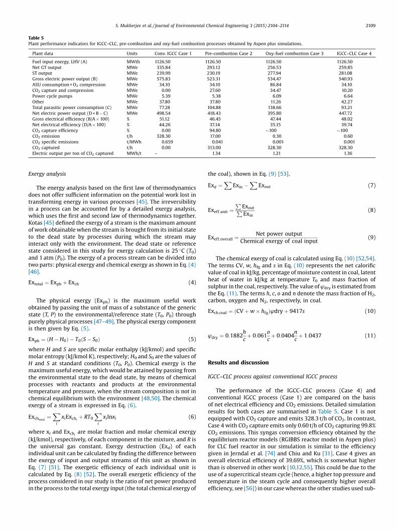
Table 5Plant performance indicators for IGCC–CLC, pre-combustion and oxy-fuel combustion processes obtained by Aspen plus simulations.
Plant data Units Conv. IGCC Case 1 Pre-combustion Case 2 Oxy-fuel combustion Case 3 IGCC–CLC Case 4
Fuel input energy, LHV (A) MWth 1126.50 1126.50 1126.50 1126.50Net GT output MWe 335.84 293.12 256.53 259.85ST output MWe 239.99 230.19 277.94 281.08Gross electric power output (B) MWe 575.83 523.31 534.47 540.93ASU consumption + O2 compression MWe 34.10 34.10 86.84 34.10CO2 capture and compression MWe 0.00 27.60 34.47 10.20Power cycle pumps MWe 5.39 5.38 6.09 6.64Other MWe 37.80 37.80 11.26 42.27Total parasitic power consumption (C) MWe 77.28 104.88 138.66 93.21Net electric power output (D = B � C) MWe 498.54 418.43 395.80 447.72Gross electrical efficiency (B/A � 100) % 51.12 46.45 47.44 48.02Net electrical efficiency (D/A � 100) % 44.26 37.14 35.15 39.74CO2 capture efficiency % 0.00 94.80 �100 �100CO2 emission t/h 328.30 17.00 0.30 0.60CO2 specific emissions t/MWh 0.659 0.041 0.001 0.001CO2 captured t/h 0.00 313.00 328.30 328.30Electric output per ton of CO2 captured MWh/t – 1.34 1.21 1.36
S. Mukherjee et al. / Journal of Environmental Chemical Engineering 3 (2015) 2104–2114 2109
Exergy analysis
The energy analysis based on the first law of thermodynamicsdoes not offer sufficient information on the potential work lost intransforming energy in various processes [45]. The irreversibilityin a process can be accounted for by a detailed exergy analysis,which uses the first and second law of thermodynamics together.Kotas [45] defined the exergy of a stream is the maximum amountof work obtainable when the stream is brought from its initial stateto the dead state by processes during which the stream mayinteract only with the environment. The dead state or referencestate considered in this study for exergy calculation is 25 �C (T0)and 1 atm (P0). The exergy of a process stream can be divided intotwo parts: physical exergy and chemical exergy as shown in Eq. (4)[46].
Extotal ¼ Exph þ Exch (4)
The physical exergy (Exph) is the maximum useful workobtained by passing the unit of mass of a substance of the genericstate (T, P) to the environmental/reference state (T0, P0) throughpurely physical processes [47–49]. The physical exergy componentis then given by Eq. (5).
Exph ¼ ðH � H0Þ � T0ðS � S0Þ (5)
where H and S are specific molar enthalpy (kJ/kmol) and specificmolar entropy (kJ/kmol K), respectively; H0 and S0 are the values ofH and S at standard conditions (T0, P0). Chemical exergy is themaximum useful energy, which would be attained by passing fromthe environmental state to the dead state, by means of chemicalprocesses with reactants and products at the environmentaltemperature and pressure, when the stream composition is not inchemical equilibrium with the environment [48,50]. The chemicalexergy of a stream is expressed in Eq. (6).
Exchtotal¼
X
i
xiExchiþ RT0
X
i
xilnxi (6)
where xi and Exchiare molar fraction and molar chemical exergy
(kJ/kmol), respectively, of each component in the mixture, and R isthe universal gas constant. Exergy destruction (Exd) of eachindividual unit can be calculated by finding the difference betweenthe exergy of input and output streams of this unit as shown inEq. (7) [51]. The exergetic efficiency of each individual unit iscalculated by Eq. (8) [52]. The overall exergetic efficiency of theprocess considered in our study is the ratio of net power producedin the process to the total exergy input (the total chemical exergy of
the coal), shown in Eq. (9) [53].
Exd ¼X
Exin �X
Exout (7)
Exeff;unit ¼P
ExoutPExin
(8)
Exeff;overall ¼Net power output
Chemical exergy of coal input(9)
The chemical exergy of coal is calculated using Eq. (10) [52,54].The terms CV, w, hfg and s in Eq. (10) represents the net calorificvalue of coal in kJ/kg, percentage of moisture content in coal, latentheat of water in kJ/kg at temperature T0 and mass fraction ofsulphur in the coal, respectively. The value of ’dry is estimated fromthe Eq. (11). The terms h, c, o and n denote the mass fraction of H2,carbon, oxygen and N2, respectively, in coal.
Exch;coal ¼ ðCV þ w � hfgÞ’dry þ 9417s (10)
’dry ¼ 0:1882hcþ 0:061
ocþ 0:0404
ncþ 1:0437 (11)
Results and discussion
IGCC–CLC process against conventional IGCC process
The performance of the IGCC–CLC process (Case 4) andconventional IGCC process (Case 1) are compared on the basisof net electrical efficiency and CO2 emissions. Detailed simulationresults for both cases are summarised in Table 5. Case 1 is notequipped with CO2 capture and emits 328.3 t/h of CO2. In contrast,Case 4 with CO2 capture emits only 0.60 t/h of CO2 capturing 99.8%CO2 emissions. This syngas conversion efficiency obtained by theequilibrium reactor models (RGIBBS reactor model in Aspen plus)for CLC fuel reactor in our simulation is similar to the efficiencygiven in Jerndal et al. [74] and Chiu and Ku [31]. Case 4 gives anoverall electrical efficiency of 39.69%, which is somewhat higherthan is observed in other work [10,12,55]. This could be due to theuse of a supercritical steam cycle (hence, a higher top pressure andtemperature in the steam cycle and consequently higher overallefficiency, see [56]) in our case whereas the other studies used sub-
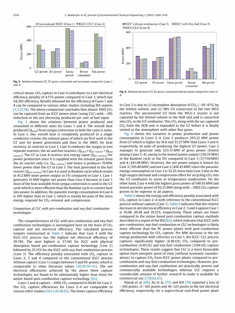
Fig. 5. Relation between GT, ST, gross, consumed and net power output for Cases 1and 4.
Fig. 6. Relation between GT, ST, gross, consumed and net power output for Cases 2–4.
2110 S. Mukherjee et al. / Journal of Environmental Chemical Engineering 3 (2015) 2104–2114
critical steam. CO2 capture in Case 4 contributes to a net electricalefficiency penalty of 4.57%-points compared to Case 1, which has44.26% efficiency. Results obtained for the efficiency of Cases 1 and4 can be compared to various other studies including IEA reports[1,3,57,58]. The above comparison concludes that almost 100% CO2
can be captured from an IGCC power plant (using CLC) with �10%reduction in the net electricity produced per unit of fuel input.
Fig. 5 shows the relations between power produced andconsumed in different units for Cases 1 and 4. The overall heatproduced (Qtotal) from syngas conversion in both the cases is same.In Case 1, this overall heat is completely produced in a singlecombustor reactor, the exhaust gases of which are first used in theGT unit for power generation and then in the HRSG for heatrecovery. In contrast to Case 1, Case 4 combusts the syngas in twoseparate reactors; the air and fuel reactors, (Qtotal = Qair reactor + Qfuel
reactor). The GT in Case 4 receives less energy input (Qair reactor) forpower production since it is supplied with the exhaust gases fromthe air reactor only (i.e. Qair reactor) and hence it produces 76 MWlower power than the GT in Case 1. The heat generated in the fuelreactor (Qfuel reactor) in Case 4 is used in Rankine cycle which resultsin 41.2 MW more power output in STs compared to Case 1. Case 1generates 51 MW higher net power than Case 4 because in Case 1most of the heat available from syngas conversion is used in the GTcycle which is more efficient than the Rankine cycle to convert heatinto power. In addition, the parasitic energy consumption in Case 4is 20% higher than in Case 1, which is mainly because of the extraenergy required for CO2 removal and compression.
Comparison of CLC with pre-combustion and oxy-fuel combustiontechnologies
The competitiveness of CLC with pre-combustion and oxy-fuelcombustion technologies is investigated here on the basis of CO2
capture and net electrical efficiency. The calculated processoutputs summarised in Table 5 indicate that Case 4 with theIGCC–CLC process has the highest net electrical efficiency of39.74%. The next highest is 37.14% for IGCC with physicalabsorption based pre-combustion capture technology (Case 2)followed by 35.15% for the IGCC with oxy-fuel combustion process(Case 3). The efficiency penalty associated with CO2 capture inCases 2, 3 and 4 compared to the conventional IGCC processwithout capture (Case 1) ranges between 5 and 9%-points, which iscomparable to other literature values [10,29,59–61]. The netelectrical efficiencies achieved by the above three capturetechnologies are found to be substantially higher than those foramine based post-combustion capture technology [62].
Cases 3 and 4 capture �100% CO2 compared to 94.8% for Case 2.The CO2 capture efficiencies for Cases 2–4 are comparable tovarious other studies [10,11,20,58,62]. The lower capture efficiency
in Case 2 is due to (i) incomplete absorption of CO2 (�95–97%) bythe Selexol solvent, and (ii) 98% CO conversion in the two WGSreactors. The unconverted CO from the WGS-2 reactor is notcaptured by the Selexol solvent in the AGR unit and is convertedinto CO2 in the GT combustor. This CO2 along with the un-capturedCO2 from the AGR unit is expanded in the GT before it is finallyvented to the atmosphere with other flue gases.
Fig. 6 shows the variation in power production and powerconsumption in Cases 2–4. Case 2 produces 293.12 MW powerfrom GT which is higher by 36.6 and 33.27 MW than Cases 3 and 4,respectively. In spite of producing the highest GT power, Case 2manages to generate only 523.31 MW of gross power (lowestamong Cases 2–4), owing to the lowest power output (230.19 MW)in the Rankine cycle or the STs compared to Case 3 (277.94 MW)and 4 (281.08 MW). However, the net power output is lowest forCase 3 (395.80 MW) and not Case 2 (418.43 MW) since the parasiticenergy consumption in Case 3 is 32.2% more than Case 2 due to thehigh oxygen demand and compression effort for recycling CO2 intothe GT combustor to assist in temperature moderation. On theother hand, Case 4 with the highest gross power of 540.93 MW andlowest parasitic power of 93.21 MW along with �100% CO2 captureproves to be superior in all aspects.
Table 6 shows the energy and efficiency penalty associated withCO2 capture in Cases 2–4 with reference to the conventional IGCCprocess without capture (Case 1). Table 6 indicates that the relativedecrease in net electrical efficiency in Case 2, 3 and 4 against Case 1is 16.08, 20.58 and 10.21%, respectively. These values are lowercompared to the amine based post-combustion capture methodsdescribed in a report of the IEA [62], which indicates that IGCC withpre-combustion, oxy-fuel combustion or CLC technologies is likelymore efficient than the PC power plants with post-combustioncapture technology for CO2 capture. Per MW decrease in the netenergy production with reference to Case 1, the IGCC–CLC processcaptures significantly higher (6.46 t/h) CO2 compared to pre-combustion (4.10 t/h) and oxy-fuel combustion (3.04 t/h) capturetechnologies. These results suggest that CLC is a more favourableoption from energetic point of view (without economic consider-ations) to capture CO2 from IGCC power plants compared to pre-combustion and oxy-fuel combustion technologies. However, pre-combustion and oxy-fuel combustion are practically proven andcommercially available technologies whereas CLC requires aconsiderable amount of further research to make it available forcommercial use [7,18,62,63].
Hanak et al. [69], Xu et al. [73] and IEA [70] reported a loss of�10% points, 11–16% points and 10–12% points in the net electricalefficiency, respectively, for a supercritical coal-fired power plant
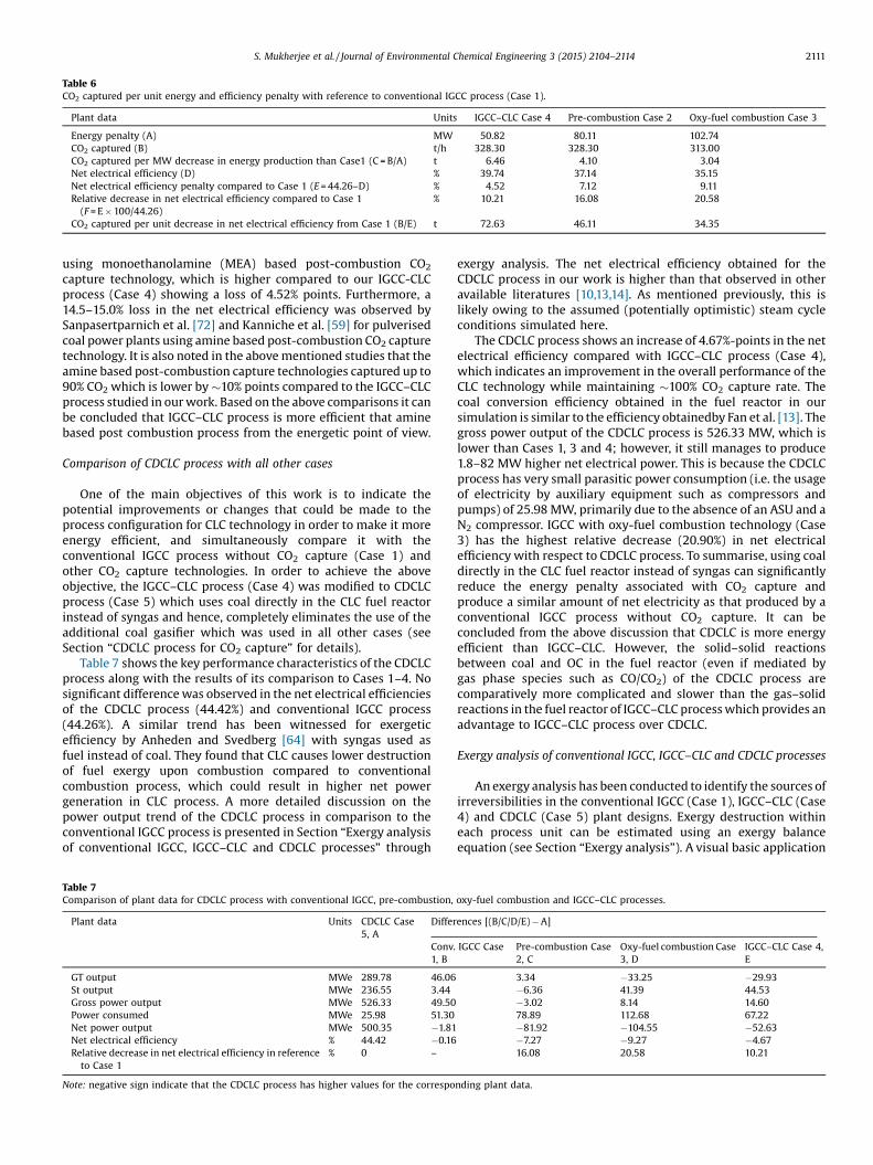
Table 6CO2 captured per unit energy and efficiency penalty with reference to conventional IGCC process (Case 1).
Plant data Units IGCC–CLC Case 4 Pre-combustion Case 2 Oxy-fuel combustion Case 3
Energy penalty (A) MW 50.82 80.11 102.74CO2 captured (B) t/h 328.30 328.30 313.00CO2 captured per MW decrease in energy production than Case1 (C = B/A) t 6.46 4.10 3.04Net electrical efficiency (D) % 39.74 37.14 35.15Net electrical efficiency penalty compared to Case 1 (E = 44.26–D) % 4.52 7.12 9.11Relative decrease in net electrical efficiency compared to Case 1(F = E � 100/44.26)
% 10.21 16.08 20.58
CO2 captured per unit decrease in net electrical efficiency from Case 1 (B/E) t 72.63 46.11 34.35
S. Mukherjee et al. / Journal of Environmental Chemical Engineering 3 (2015) 2104–2114 2111
using monoethanolamine (MEA) based post-combustion CO2
capture technology, which is higher compared to our IGCC-CLCprocess (Case 4) showing a loss of 4.52% points. Furthermore, a14.5–15.0% loss in the net electrical efficiency was observed bySanpasertparnich et al. [72] and Kanniche et al. [59] for pulverisedcoal power plants using amine based post-combustion CO2 capturetechnology. It is also noted in the above mentioned studies that theamine based post-combustion capture technologies captured up to90% CO2 which is lower by �10% points compared to the IGCC–CLCprocess studied in our work. Based on the above comparisons it canbe concluded that IGCC–CLC process is more efficient that aminebased post combustion process from the energetic point of view.
Comparison of CDCLC process with all other cases
One of the main objectives of this work is to indicate thepotential improvements or changes that could be made to theprocess configuration for CLC technology in order to make it moreenergy efficient, and simultaneously compare it with theconventional IGCC process without CO2 capture (Case 1) andother CO2 capture technologies. In order to achieve the aboveobjective, the IGCC–CLC process (Case 4) was modified to CDCLCprocess (Case 5) which uses coal directly in the CLC fuel reactorinstead of syngas and hence, completely eliminates the use of theadditional coal gasifier which was used in all other cases (seeSection “CDCLC process for CO2 capture” for details).
Table 7 shows the key performance characteristics of the CDCLCprocess along with the results of its comparison to Cases 1–4. Nosignificant difference was observed in the net electrical efficienciesof the CDCLC process (44.42%) and conventional IGCC process(44.26%). A similar trend has been witnessed for exergeticefficiency by Anheden and Svedberg [64] with syngas used asfuel instead of coal. They found that CLC causes lower destructionof fuel exergy upon combustion compared to conventionalcombustion process, which could result in higher net powergeneration in CLC process. A more detailed discussion on thepower output trend of the CDCLC process in comparison to theconventional IGCC process is presented in Section “Exergy analysisof conventional IGCC, IGCC–CLC and CDCLC processes” through
Table 7Comparison of plant data for CDCLC process with conventional IGCC, pre-combustion,
Plant data Units CDCLC Case5, A
Differ
Conv.1, B
GT output MWe 289.78 46.06St output MWe 236.55 3.44
Gross power output MWe 526.33 49.50Power consumed MWe 25.98 51.30Net power output MWe 500.35 �1.81Net electrical efficiency % 44.42 �0.16Relative decrease in net electrical efficiency in referenceto Case 1
% 0 –
Note: negative sign indicate that the CDCLC process has higher values for the correspo
exergy analysis. The net electrical efficiency obtained for theCDCLC process in our work is higher than that observed in otheravailable literatures [10,13,14]. As mentioned previously, this islikely owing to the assumed (potentially optimistic) steam cycleconditions simulated here.
The CDCLC process shows an increase of 4.67%-points in the netelectrical efficiency compared with IGCC–CLC process (Case 4),which indicates an improvement in the overall performance of theCLC technology while maintaining �100% CO2 capture rate. Thecoal conversion efficiency obtained in the fuel reactor in oursimulation is similar to the efficiency obtainedby Fan et al. [13]. Thegross power output of the CDCLC process is 526.33 MW, which islower than Cases 1, 3 and 4; however, it still manages to produce1.8–82 MW higher net electrical power. This is because the CDCLCprocess has very small parasitic power consumption (i.e. the usageof electricity by auxiliary equipment such as compressors andpumps) of 25.98 MW, primarily due to the absence of an ASU and aN2 compressor. IGCC with oxy-fuel combustion technology (Case3) has the highest relative decrease (20.90%) in net electricalefficiency with respect to CDCLC process. To summarise, using coaldirectly in the CLC fuel reactor instead of syngas can significantlyreduce the energy penalty associated with CO2 capture andproduce a similar amount of net electricity as that produced by aconventional IGCC process without CO2 capture. It can beconcluded from the above discussion that CDCLC is more energyefficient than IGCC–CLC. However, the solid–solid reactionsbetween coal and OC in the fuel reactor (even if mediated bygas phase species such as CO/CO2) of the CDCLC process arecomparatively more complicated and slower than the gas–solidreactions in the fuel reactor of IGCC–CLC process which provides anadvantage to IGCC–CLC process over CDCLC.
Exergy analysis of conventional IGCC, IGCC–CLC and CDCLC processes
An exergy analysis has been conducted to identify the sources ofirreversibilities in the conventional IGCC (Case 1), IGCC–CLC (Case4) and CDCLC (Case 5) plant designs. Exergy destruction withineach process unit can be estimated using an exergy balanceequation (see Section “Exergy analysis”). A visual basic application
oxy-fuel combustion and IGCC–CLC processes.
ences [(B/C/D/E) � A]
IGCC Case Pre-combustion Case2, C
Oxy-fuel combustion Case3, D
IGCC–CLC Case 4,E
3.34 �33.25 �29.93�6.36 41.39 44.53
�3.02 8.14 14.60 78.89 112.68 67.22
�81.92 �104.55 �52.63 �7.27 �9.27 �4.67
16.08 20.58 10.21
nding plant data.
2112 S. Mukherjee et al. / Journal of Environmental Chemical Engineering 3 (2015) 2104–2114
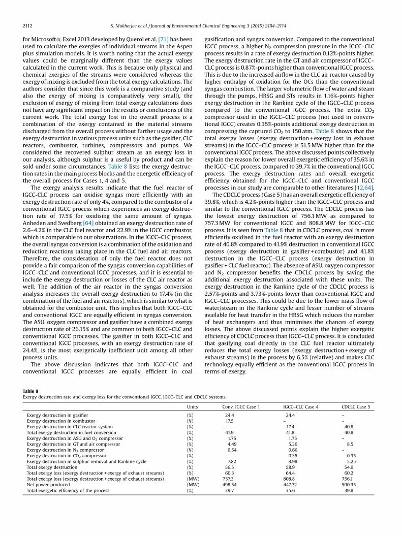
for Microsoft1 Excel 2013 developed by Querol et al. [71] has beenused to calculate the exergies of individual streams in the Aspenplus simulation models. It is worth noting that the actual exergyvalues could be marginally different than the exergy valuescalculated in the current work. This is because only physical andchemical exergies of the streams were considered whereas theexergy of mixing is excluded from the total exergy calculations. Theauthors consider that since this work is a comparative study (andalso the exergy of mixing is comparatively very small), theexclusion of exergy of mixing from total exergy calculations doesnot have any significant impact on the results or conclusions of thecurrent work. The total exergy lost in the overall process is acombination of the exergy contained in the material streamsdischarged from the overall process without further usage and theexergy destruction in various process units such as the gasifier, CLCreactors, combustor, turbines, compressors and pumps. Weconsidered the recovered sulphur stream as an exergy loss inour analysis, although sulphur is a useful by product and can besold under some circumstances. Table 8 lists the exergy destruc-tion rates in the main process blocks and the energetic efficiency ofthe overall process for Cases 1, 4 and 5.
The exergy analysis results indicate that the fuel reactor ofIGCC-CLC process can oxidise syngas more efficiently with anexergy destruction rate of only 4%, compared to the combustor of aconventional IGCC process which experiences an exergy destruc-tion rate of 17.5% for oxidising the same amount of syngas.Anheden and Svedberg [64] obtained an exergy destruction rate of2.6–4.2% in the CLC fuel reactor and 22.9% in the IGCC combustor,which is comparable to our observations. In the IGCC–CLC process,the overall syngas conversion is a combination of the oxidation andreduction reactions taking place in the CLC fuel and air reactors.Therefore, the consideration of only the fuel reactor does notprovide a fair comparison of the syngas conversion capabilities ofIGCC–CLC and conventional IGCC processes, and it is essential toinclude the exergy destruction or losses of the CLC air reactor aswell. The addition of the air reactor in the syngas conversionanalysis increases the overall exergy destruction to 17.4% (in thecombination of the fuel and air reactors), which is similar to what isobtained for the combustor unit. This implies that both IGCC–CLCand conventional IGCC are equally efficient in syngas conversion.The ASU, oxygen compressor and gasifier have a combined exergydestruction rate of 26.15% and are common to both IGCC–CLC andconventional IGCC processes. The gasifier in both IGCC–CLC andconventional IGCC processes, with an exergy destruction rate of24.4%, is the most exergetically inefficient unit among all otherprocess units.
The above discussion indicates that both IGCC–CLC andconventional IGCC processes are equally efficient in coal
Table 8Exergy destruction rate and exergy loss for the conventional IGCC, IGCC–CLC and CDCL
Units
Exergy destruction in gasifier (%)
Exergy destruction in combustor (%)
Exergy destruction in CLC reactor system (%)
Total exergy destruction in fuel conversion (%)
Exergy destruction in ASU and O2 compressor (%)
Exergy destruction in GT and air compressor (%)
Exergy destruction in N2 compressor (%)
Exergy destruction in CO2 compressor (%)
Exergy destruction in sulphur removal and Rankine cycle (%)
Total exergy destruction (%)
Total exergy loss (exergy destruction + exergy of exhaust streams) (%)
Total exergy loss (exergy destruction + exergy of exhaust streams) (MW)
Net power produced (MW)
Total exergetic efficiency of the process (%)
gasification and syngas conversion. Compared to the conventionalIGCC process, a higher N2 compression pressure in the IGCC–CLCprocess results in a rate of exergy destruction 0.12%-points higher.The exergy destruction rate in the GT and air compressor of IGCC–CLC process is 0.87%-points higher than conventional IGCC process.This is due to the increased airflow in the CLC air reactor caused byhigher enthalpy of oxidation for the OCs than the conventionalsyngas combustion. The larger volumetric flow of water and steamthrough the pumps, HRSG and STs results in 1.16%-points higherexergy destruction in the Rankine cycle of the IGCC–CLC processcompared to the conventional IGCC process. The extra CO2
compressor used in the IGCC–CLC process (not used in conven-tional IGCC) creates 0.35%-points additional exergy destruction incompressing the captured CO2 to 150 atm. Table 8 shows that thetotal exergy losses (exergy destruction + exergy lost in exhauststreams) in the IGCC–CLC process is 51.5 MW higher than for theconventional IGCC process. The above discussed points collectivelyexplain the reason for lower overall exergetic efficiency of 35.6% inthe IGCC–CLC process, compared to 39.7% in the conventional IGCCprocess. The exergy destruction rates and overall exergeticefficiency obtained for the IGCC–CLC and conventional IGCCprocesses in our study are comparable to other literatures [12,64].
The CDCLC process (Case 5) has an overall exergetic efficiency of39.8%, which is 4.2%-points higher than the IGCC–CLC process andsimilar to the conventional IGCC process. The CDCLC process hasthe lowest exergy destruction of 756.1 MW as compared to757.3 MW for conventional IGCC and 808.8 MW for IGCC–CLCprocess. It is seen from Table 8 that in CDCLC process, coal is moreefficiently oxidised in the fuel reactor with an exergy destructionrate of 40.8% compared to 41.9% destruction in conventional IGCCprocess (exergy destruction in gasifier + combustor) and 41.8%destruction in the IGCC–CLC process (exergy destruction ingasifier + CLC fuel reactor). The absence of ASU, oxygen compressorand N2 compressor benefits the CDCLC process by saving theadditional exergy destruction associated with these units. Theexergy destruction in the Rankine cycle of the CDCLC process is2.57%-points and 3.73%-points lower than conventional IGCC andIGCC–CLC processes. This could be due to the lower mass flow ofwater/steam in the Rankine cycle and lesser number of streamsavailable for heat transfer in the HRSG which reduces the numberof heat exchangers and thus minimises the chances of exergylosses. The above discussed points explain the higher exergeticefficiency of CDCLC process than IGCC–CLC process. It is concludedthat gasifying coal directly in the CLC fuel reactor ultimatelyreduces the total exergy losses (exergy destruction + exergy ofexhaust streams) in the process by 6.5% (relative) and makes CLCtechnology equally efficient as the conventional IGCC process interms of exergy.
C systems.
Conv. IGCC Case 1 IGCC–CLC Case 4 CDCLC Case 5
24.4 24.4 –
17.5 – –
– 17.4 40.841.9 41.8 40.81.75 1.75 –
4.49 5.36 8.50.54 0.66 –
– 0.35 0.357.82 8.98 5.25
56.5 58.9 54.960.3 64.4 60.2
757.3 808.8 756.1498.54 447.72 500.3539.7 35.6 39.8
S. Mukherjee et al. / Journal of Environmental Chemical Engineering 3 (2015) 2104–2114 2113
Summary and conclusion
This article evaluates (via modelling in Aspen plus) thecompetitiveness of CLC technology against pre-combustion andoxy-fuel combustion technology for IGCC plants with CO2 captureproducing electricity from coal, in five different process config-urations (four with, and one base-case without, CO2 capturetechnology). Chemical Looping Combustion (CLC) was studied fortwo different process configurations, IGCC–CLC and CDCLC, inorder to fully explore its potential. The work also examines the CLCtechnology through a detailed exergy analysis. The key conclusionsobtained from this work are as follows:
� For IGCC cases with CO2 capture (Cases 2–4), the IGCC–CLCprocess achieves the highest net electrical efficiency of 39.74%(capture efficiency �100%) followed by pre-combustion captureat 37.14% (capture efficiency �94.8%) and oxy-fuel combustioncapture at 35.15% (capture efficiency �100%). These figures arerelative to a net electrical efficiency of 44.26 for the unabatedplant.
� Modification of the IGCC–CLC process to the CDCLC process (i.e.using the coal directly in the gasification process, rather thanutilising a separate gasifier) increases the net electrical efficiencyby 4.67%-points, while maintaining the CO2 capture rate at 100%.The net electrical efficiency is then approximately equivalent tothe base case unabated system (case 1).
The detailed comparative analysis performed in this workdemonstrates that, regardless of any configuration used, the CLCtechnology is a more suitable option for CO2 capture than physicalabsorption based pre-combustion capture and oxy-fuel combus-tion capture technologies from the thermodynamic perspective.However, it is necessary to examine the economic aspects (which isout of the scope of this work), before drawing firm conclusionsregarding the selection of a capture technology. Furthermore, theimpact of degradation of the OC for CLC and Selexol for physicalabsorption technologies should be examined for completetechnoeconomic evaluation; life cycle analysis is also necessaryfor a complete understanding of the environmental impact of theprocess.
Competing interests
The authors declare no competing financial interest.
Acknowledgement
This work was supported by the joint UK-China Engineering andPhysical Research Council (EPSRC) funded project [grant numberEP/I010912/1] “Multi-scale evaluation of advanced technologiesfor capturing the CO2: Chemical looping applied to solid fuels”. PKthanks the consortium members from the Universities of Cam-bridge, Nottingham, Tsinghua and South-East (China) for theircooperation. The Surrey team is also grateful to the Department ofCivil and Environmental Engineering at the University of Surrey foradditional funding support for this work.
Appendix A. Supplementary data
Supplementary data associated with this article can be found, inthe online version, at 10.1016/j.jece.2015.07.018.
References
[1] IEA, CO2 Emissions from Fuel Combustion, International Energy Agency, 2012.[2] BP, BP Statistical Review of World Energy, BP plc, 2014.
[3] IEA, World Energy Outlook, International Energy Agency, 2009.[4] IEA, key World Energy Statistics, Key World Energy Statistics, International
Energy Agency, 2013.[5] WCI, Coal Meeting the Climate Challenge, World Coal Institute, 2009.[6] S. Anderson, R. Newell, Prospects for carbon capture and storage technologies,
Annu. Rev. Environ. Resour. 29 (1) (2004) 109–142, doi:http://dx.doi.org/10.1146/annurev.energy.29.082703.145619.
[7] M.E. Boot-Handford, J.C. Abanades, E.J. Anthony, M.J. Blunt, S. Brandani, N. MacDowell, J.R. Fernández, M. Ferrari, R. Gross, J.P. Hallett, R.S. Haszeldine, P.Heptonstall, A. Lyngfelt, Z. Makuch, E. Mangano, R.T.J. Porter, M. Pourka-shanian, G.T. Rochelle, N. Shah, J.G. Yao, P.S. Fennell, Carbon capture andstorage update, Energ. Environ. Sci. 7 (1) (2014) 130–189, doi:http://dx.doi.org/10.1039/C3EE42350F.
[8] J. Gibbins, H. Chalmers, Carbon capture and storage, Energy Policy 36 (12)(2008) 4317–4322, doi:http://dx.doi.org/10.1016/j.enpol.2008.09.058.
[9] A.J. Minchener, J.T. McMullan, Sustainable clean coal power generation withina European context—the view in 2006, Fuel 86 (14) (2007) 2124–2133, doi:http://dx.doi.org/10.1016/j.fuel.2007.01.022.
[10] A.-M. Cormos, C.-C. Cormos, Investigation of hydrogen and power co-gener-ation based on direct coal chemical looping systems, Int. J. Hydrogen Energy 39(5) (2014) 2067–2077, doi:http://dx.doi.org/10.1016/j.ijhydene.2013.11.123.
[11] C.-C. Cormos, Evaluation of syngas-based chemical looping applications forhydrogen and power co-generation with CCS, Int. J. Hydrogen Energy 37 (18)(2012) 13371–13386, doi:http://dx.doi.org/10.1016/j.ijhydene.2012.06.090.
[12] B. Erlach, M. Schmidt, G. Tsatsaronis, Comparison of carbon capture IGCC withpre-combustion decarbonisation and with chemical-looping combustion,Energy 36 (6) (2011) 3804–3815, doi:http://dx.doi.org/10.1016/j.ener-gy.2010.08.038.
[13] L.-S. Fan, L. Zeng, W. Wang, S. Luo, Chemical looping processes for CO2 captureand carbonaceous fuel conversion—prospect and opportunity, Energy Environ.Sci. 5 (6) (2012) 7254–7280, doi:http://dx.doi.org/10.1039/c2ee03198a.
[14] L.S. Fan, Chemical Looping Systems for Fossil Energy Conversions, Wiley, 2010.[15] A. Lyngfelt, B. Leckner, T. Mattisson, A fluidized-bed combustion process with
inherent CO2 separation; application of chemical-looping combustion, Chem.Eng. Sci. 56 (10) (2001) 3101–3113, doi:http://dx.doi.org/10.1016/S0009-2509(01)00007-0.
[16] A. Tong, S. Bayham, M.V. Kathe, L. Zeng, S. Luo, L.-S. Fan, Iron-based syngaschemical looping process and coal-direct chemical looping process devel-opment at Ohio State University, Appl. Energy 113 (2014) 1836–1845, doi:http://dx.doi.org/10.1016/j.apenergy.2013.05.024.
[17] P. Casero, F.G. Peña, P. Coca, J. Trujillo, ELCOGAS 14 MWth pre-combustioncarbon dioxide capture pilot. Technical & economical achievements, Fuel 116(2014) 804–811, doi:http://dx.doi.org/10.1016/j.fuel.2013.07.027.
[18] P. Chiesa, S. Consonni, T. Kreutz, W. Robert, Co-production of hydrogen,electricity and CO from coal with commercially ready technology. Part A:performance and emissions, Int. J. Hydrogen Energy 30 (7) (2005) 747–767,doi:http://dx.doi.org/10.1016/j.ijhydene.2004.08.002.
[19] C. Kunze, H. Spliethoff, Assessment of oxy-fuel, pre- and post-combustion-based carbon capture for future IGCC plants, Appl. Energy 94 (2012) 109–116,doi:http://dx.doi.org/10.1016/j.apenergy.2012.01.013.
[20] Y. Oki, J. Inumaru, S. Hara, M. Kobayashi, H. Watanabe, S. Umemoto, H. Makino,Development of oxy-fuel IGCC system with CO2 recirculation for CO2 capture,Energy Procedia 4 (2011) 1066–1073, doi:http://dx.doi.org/10.1016/j.egy-pro.2011.01.156.
[21] C. Trapp, Advances in Model-Based Design of Flexible and Prompt EnergySystems—the CO2 Capture Plant at the Buggenum IGCC Power Station as a TestCase, Aerodynamics, Wind Energy, Flight Performance and Propulsion, Uni-versity of Stuttgart, Netherlands, 2014.
[22] C. Kunze, H. Spliethoff, Modelling of an IGCC plant with carbon capture for2020, Fuel Process. Technol. 91 (8) (2010) 934–941, doi:http://dx.doi.org/10.1016/j.fuproc.2010.02.017.
[23] C. Kunze, H. Spliethoff, Modelling, comparison and operation experiences ofentrained flow gasifier, Energ. Convers. Manage. 52 (5) (2011) 2135–2141, doi:http://dx.doi.org/10.1016/j.enconman.2010.10.049.
[24] L. Zheng, E. Furinsky, Comparison of shell, Texaco, BGL and KRW gasifiers aspart of IGCC plant computer simulations, Energy Convers. Manag. 46 (11–12)(2005) 1767–1779, doi:http://dx.doi.org/10.1016/j.enconman.2004.09.004.
[25] C.-C. Cormos, Evaluation of energy integration aspects for IGCC-based hy-drogen and electricity co-production with carbon capture and storage, Int. J.Hydrogen Energy 35 (14) (2010) 7485–7497, doi:http://dx.doi.org/10.1016/j.ijhydene.2010.04.160.
[26] A. Brunetti, E. Drioli, G. Barbieri, Medium/high temperature water gas shiftreaction in a Pd–Ag membrane reactor: an experimental investigation, RSCAdv. 2 (1) (2012) 226–233, doi:http://dx.doi.org/10.1039/C1RA00569C.
[27] M. Bracht, P.T. Alderliesten, R. Kloster, R. Pruschek, G. Haupt, E. Xue, J.R.H. Ross,M.K. Koukou, N. Papayannakos, Water gas shift membrane reactor for CO2
control in IGCC systems: techno-economic feasibility study, Energy Convers.Manag. 38 (1997) S159–S164, doi:http://dx.doi.org/10.1016/S0196-8904(96)00263-4.
[28] C.-C. Cormos, Assessment of hydrogen and electricity co-production schemesbased on gasification process with carbon capture and storage, Int. J. HydrogenEnergy 34 (15) (2009) 6065–6077, doi:http://dx.doi.org/10.1016/j.ijhy-dene.2009.05.054.
[29] J. Urech, L. Tock, T. Harkin, A. Hoadley, F. Maréchal, An assessment of differentsolvent-based capture technologies within an IGCC–CCS power plant, Energy64 (2014) 268–276, doi:http://dx.doi.org/10.1016/j.energy.2013.10.081.
2114 S. Mukherjee et al. / Journal of Environmental Chemical Engineering 3 (2015) 2104–2114
[30] F. Li, L. Zeng, L.G. Velazquez-Vargas, Z. Yoscovits, L.-S. Fan, Syngas chemicallooping gasification process: bench-scale studies and reactor simulations,AIChE J. 56 (8) (2010) 2186–2199, doi:http://dx.doi.org/10.1002/aic.12093.
[31] P.-C. Chiu, Y. Ku, Chemical looping process—a novel technology for inherentCO2 capture, Aerosol Air Qual. Res. 12 (2012) 1421–1432, doi:http://dx.doi.org/10.4209/aaqr.2012.08.0215.
[32] J. Adanez, A. Abad, F. Garcia-Labiano, P. Gayan, L.F. de Diego, Progress inchemical-looping combustion and reforming technologies, Prog. EnergyCombust. Sci. 38 (2) (2012) 215–282, doi:http://dx.doi.org/10.1016/j.pecs.2011.09.001.
[33] S. Chen, W. Xiang, Z. Xue, X. Sun, Experimental investigation of chemicallooping hydrogen generation using iron oxides in a batch fluidized bed, Proc.Combust. Inst. 33 (2) (2011) 2691–2699, doi:http://dx.doi.org/10.1016/j.proci.2010.08.010.
[34] R. Sharma, A. Delebarre, B. Alappat, Chemical-looping combustion—an over-view and application of the recirculating fluidized bed reactor for improve-ment, Int. J. Energy Res. 38 (10) (2014) 1331–1350, doi:http://dx.doi.org/10.1002/er.3151.
[35] G. Azimi, M. Keller, A. Mehdipoor, H. Leion, Experimental evaluation andmodeling of steam gasification and hydrogen inhibition in chemical-loopingcombustion with solid fuel, Int. J. Greenhouse Gas Control 11 (2012) 1–10, doi:http://dx.doi.org/10.1016/j.ijggc.2012.07.018.
[36] A. Cuadrat, A. Abad, L.F. de Diego, F. García-Labiano, P. Gayán, J. Adánez, Promptconsiderations on the design of chemical-looping combustion of coal fromexperimental tests, Fuel 97 (2012) 219–232, doi:http://dx.doi.org/10.1016/j.fuel.2012.01.050.
[37] L.-S. Fan, Chemical Looping Systems for Fossil Energy Conversions, Wiley-AIChe, USA, 2010.
[38] L. Fan, F. Li, S. Ramkumar, Utilization of chemical looping strategy in coalgasification processes, Particuology 6 (3) (2008) 131–142, doi:http://dx.doi.org/10.1016/j.partic.2008.03.005.
[39] F. He, N. Galinsky, F. Li, Chemical looping gasification of solid fuels usingbimetallic oxygen carrier particles—feasibility assessment and process sim-ulations, Int. J. Hydrogen Energy 38 (19) (2013) 7839–7854, doi:http://dx.doi.org/10.1016/j.ijhydene.2013.04.054.
[40] T. Song, T. Shen, L. Shen, J. Xiao, H. Gu, S. Zhang, Evaluation of hematite oxygencarrier in chemical-looping combustion of coal, Fuel 104 (2013) 244–252, doi:http://dx.doi.org/10.1016/j.fuel.2012.09.030.
[41] B. Wang, H. Lv, H. Zhao, C. Zheng, Experimental and simulated investigation ofchemical looping combustion of coal with Fe2O3 based oxygen carrier, Pro-cedia Eng. 16 (2011) 390–395, doi:http://dx.doi.org/10.1016/j.pro-eng.2011.08.1100.
[42] L. Zeng, F. He, F. Li, L.-S. Fan, Coal-direct chemical looping gasification forhydrogen production: reactor modeling and process simulation, Energy Fuels26 (6) (2012) 3680–3690, doi:http://dx.doi.org/10.1021/ef3003685.
[43] Aspentech, Physical Property Methods and Models, Aspen Physical PropertySystem vol. 11, Aspentech, Cambridge, USA, 20011.
[44] Aspentech, Physical Property Methods, Aspen Physical Property System,Aspentech, Burlington, USA, 2010.
[45] T.J. Kotas, The Exergy Method of Thermal Plant Analysis, Anchor Brendon Ltd,Essex, England, 1985.
[46] A.P. Hinderink, F.P.J.M. Kerkhof, A.B.K. Lie, J. De Swaan Arons, H.J. Van Der Kooi,Exergy analysis with a flowsheeting simulator—I. Theory; calculating exergiesof material streams, Chem. Eng. Sci. 51 (20) (1996) 4693–4700, doi:http://dx.doi.org/10.1016/0009-2509(96)00220-5.
[47] A. Aspelund, D.O. Berstad, T. Gundersen, An extended pinch analysis anddesign procedure utilizing pressure based exergy for subambient cooling,Appl. Therm. Eng. 27 (16) (2007) 2633–2649, doi:http://dx.doi.org/10.1016/j.applthermaleng.2007.04.017.
[48] I. Dincer, M.A. Rosen, Exergy: Energy, Environment and Sustainable Devel-opment, Elsevier, 2007.
[49] S. Harvey, N.D. Kane, Analysis of a reheat gas turbine cycle with chemicalrecuperation using aspen, Energ. Convers. Manage. 38 (15–17) (1997) 1671–1679, doi:http://dx.doi.org/10.1016/S0196-8904(96)00208-7.
[50] E. Querol, B. Gonzalez-Regueral, J.L. Perez-Benedito, Practical Approach toExergy and Thermoeconomic Analyses of Industrial Processes, Springer, 2013.
[51] G.P. Verkhivker, B.V. Kosoy, On the exergy analysis of power plants, EnergyConvers. Manag. 42 (18) (2001) 2053–2059, doi:http://dx.doi.org/10.1016/S0196-8904(00)00170-9.
[52] R.S. El-Emam, I. Dincer, G.F. Naterer, Energy and exergy analyses of an inte-grated SOFC and coal gasification system, Int. J. Hydrogen Energy 37 (2) (2012)1689–1697, doi:http://dx.doi.org/10.1016/j.ijhydene.2011.09.139.
[53] H. Ozcan, I. Dincer, Thermodynamic analysis of a combined chemical looping-based trigeneration system, Energ. Convers. Manage. 85 (2014) 477–487, doi:http://dx.doi.org/10.1016/j.enconman.2014.06.011.
[54] I. Dincer, M.A. Rosen, Exergy: Energy, Environment and Sustainable Devel-opment, second edition, Elsevier, 2012.
[55] C.-C. Cormos, Evaluation of iron based chemical looping for hydrogen andelectricity co-production by gasification process with carbon capture andstorage, Int. J. Hydrogen Energy 35 (6) (2010) 2278–2289, doi:http://dx.doi.org/10.1016/j.ijhydene.2010.01.033.
[56] L.F. Pellegrini, S. de Oliveira Júnior, J.C. Burbano, Supercritical steam cycles andbiomass integrated gasification combined cycles for sugarcane mills, Energy35 (2) (2010) 1172–1180, doi:http://dx.doi.org/10.1016/j.energy.2009.06.011.
[57] J. Davison, Performance and costs of power plants with capture and storage ofCO2, Energy 32 (7) (2007) 1163–1176, doi:http://dx.doi.org/10.1016/j.ener-gy.2006.07.039.
[58] IEA, CO2 Capture and Storage, International Energy Agency, 2008.[59] M. Kanniche, R. Gros-Bonnivard, P. Jaud, J. Valle-Marcos, J.-M. Amann, C.
Bouallou, Pre-combustion, post-combustion and oxy-combustion in thermalpower plant for CO2 capture, Appl. Therm. Eng. 30 (1) (2010) 53–62, doi:http://dx.doi.org/10.1016/j.applthermaleng.2009.05.005.
[60] A. Padurean, C.-C. Cormos, P.-S. Agachi, Pre-combustion carbon dioxide cap-ture by gas–liquid absorption for integrated gasification combined cyclepower plants, Int. J. Greenhouse Gas Control 7 (2012) 1–11, doi:http://dx.doi.org/10.1016/j.ijggc.2011.12.007.
[61] S. Rezvani, Y. Huang, D. McIlveen-Wright, N. Hewitt, J.D. Mondol, Comparativeassessment of coal fired IGCC systems with CO2 capture using physical ab-sorption, membrane reactors and chemical looping, Fuel 88 (12) (2009) 2463–2472, doi:http://dx.doi.org/10.1016/j.fuel.2009.04.021.
[62] IEA, Cost and Performance of Carbon Dioxide Capture from Power Generation,International Energy Agency, 2011.
[63] T. Uchida, T. Goto, T. Yamada, T. Kiga, C. Spero, Oxyfuel combustion as CO2
capture technology advancing for practical use—callide Oxyfuel Project, En-ergy Procedia 37 (2013) 1471–1479, doi:http://dx.doi.org/10.1016/j.egy-pro.2013.06.022.
[64] M. Anheden, G. Svedberg, Exergy analysis of chemical-looping combustionsystems, Energy Convers. Manag. 39 (16–18) (1998) 1967–1980, doi:http://dx.doi.org/10.1016/S0196-8904(98)00052-1.
[65] N. Casas, J. Schell, L. Joss, M. Mazzotti, A parametric study of a PSA process forpre-combustion CO2 capture, Sep. Purif. Technol. 104 (2013) 183–192, doi:http://dx.doi.org/10.1016/j.seppur.2012.11.018.
[66] Y. Li, Q. Fu, M. Flytzani-Stephanopoulos, Low-temperature water-gas shiftreaction over Cu� and Ni-loaded cerium oxide catalysts, Appl. Catal. B Environ.27 (3) (2000) 179–191, doi:http://dx.doi.org/10.1016/S0926-3373(00)00147-8.
[67] Y. Liu, Z.-S. Li, L. Xu, N. Cai, Effect of sorbent type on the sorption enhancedwater gas shift process in a fluidized bed reactor, Ind. Eng. Chem. Res. 51 (37)(2012) 11989–11997, doi:http://dx.doi.org/10.1021/ie301100y.
[68] J. Schell, N. Casas, D. Marx, M. Mazzotti, Precombustion CO2 capture bypressure swing adsorption (PSA): comparison of Laboratory PSA experimentsand simulations, Ind. Eng. Chem. Res. 52 (24) (2013) 8311–8322, doi:http://dx.doi.org/10.1021/ie3026532.
[69] D.P. Hanak, C. Biliyok, H. Yeung, R. Białecki, Heat integration and exergyanalysis for a supercritical high-ash coal-fired power plant integrated with apost-combustion carbon capture process, Fuel 134 (2014) 126–139, doi:http://dx.doi.org/10.1016/j.fuel.2014.05.036.
[70] IEA, CO2 Emissions from Fuel Combustion, IEA, 2013.[71] E. Querol, B. Gonzalez-Regueral, A. Ramos, J.L. Perez-Benedito, Novel appli-
cation for exergy and thermoeconomic analysis of processes simulated withAspen Plus1, Energy 36 (2) (2011) 964–974, doi:http://dx.doi.org/10.1016/j.energy.2010.12.013.
[72] T. Sanpasertparnich, R. Idem, I. Bolea, D. deMontigny, P. Tontiwachwuthikul,Integration of post-combustion capture and storage into a pulverized coal-fired power plant, Int. J. Greenhouse Gas Control 4 (3) (2010) 499–510, doi:http://dx.doi.org/10.1016/j.ijggc.2009.12.005.
[73] G. Xu, Y. Hu, B. Tang, Y. Yang, K. Zhang, W. Liu, Integration of the steam cycleand CO2 capture process in a decarbonization power plant, Appl. Therm. Eng.73 (1) (2014) 277–286, doi:http://dx.doi.org/10.1016/j.applth-ermaleng.2014.07.051.
[74] E. Jerndal, T. Mattisson, A. Lyngfelt, Thermal analysis of chemical-loopingcombustion, Chem. Eng. Res. Des. 84 (2006) 795–806.