Embed Size (px)
Citation preview

Journal of Magnetism and Magnetic Materials 416 (2016) 25–36
Contents lists available at ScienceDirect
Journal of Magnetism and Magnetic Materials
http://d0304-88
n CorrE-m
journal homepage: www.elsevier.com/locate/jmmm
Mixed convection in a nanofluid filled-cavity with partial slip subjectedto constant heat flux and inclined magnetic field
Muneer A. Ismael a, M.A. Mansour b, Ali J. Chamkha c,d, A.M. Rashad e,n
a Mechanical Engineering Department, Engineering College, University of Basrah, Basrah, Iraqb Department of Mathematics, Assuit University, Faculty of Science, Assuit, Egyptc Mechanical Engineering Department, Prince Mohammad Bin Fahd University, Al-Khobar 31952, Saudi Arabiad Prince Sultan Endowment for Energy and Environment, Prince Mohammad Bin Fahd University, Al-Khobar 31952, Saudi Arabiae Department of Mathematics, Aswan University, Faculty of Science, Aswan 81528, Egypt
a r t i c l e i n f o
Article history:Received 16 February 2016Received in revised form2 April 2016Accepted 4 May 2016Available online 5 May 2016
Keywords:Magnetic fieldHeat sourceLid-driven cavityPartial slipNanofluid
x.doi.org/10.1016/j.jmmm.2016.05.00653/& 2016 Elsevier B.V. All rights reserved.
esponding author.ail address: [email protected] (A.M. Ras
a b s t r a c t
Mixed convection in a lid-driven square cavity filled with Cu-water nanofluid and subjected to inclinedmagnetic field is investigated in this paper. Partial slip effect is considered along the lid driven horizontalwalls. A constant heat flux source on the left wall is considered, meanwhile the right vertical wall iscooled isothermally. The remainder cavity walls are thermally insulted. A control finite volume method isused as a numerical appliance of the governing equations. Six pertinent parameters were studied these;the orientation of the magnetic field (Φ¼0–360°), Richardson number (Ri¼0.001–1000), Hartmannumber (Ha¼0–100), the size and position of the heat source (B¼0.2–0.8, D¼0.3–0.7, respectively),nanoparticles volume fraction (ϕ¼0.0–0.1), and the lid-direction of the horizontal walls (λ¼71) wherethe positive sign means lid-driven to the right while the negative sign means lid-driven to the left. Theresults show that the orientation and the strength of the magnetic field can play a significant role incontrolling the convection under the effect of partial slip. It is also found that the natural convectiondecreases with increasing the length of the heat source for all ranges of the studied parameters, while itis do so due to the vertical distance up to Hartman number of 50, beyond this value the natural con-vection decreases with lifting the heat source narrower to the top wall.
& 2016 Elsevier B.V. All rights reserved.
1. Introduction
The developments in electronic technology, industry, environ-mental applications such as lubrication technologies, food pro-cessing and nuclear reactors have became more pronounced in therecent years [1–5]. These continually developments are cumulativeaccompanied with progress in heat rejection (cooling) methods.Mixed convection has been and will continue to be pivotal inimproving the performance of the heat rejection in electronicsources contained in enclosures. Mixed convection flow and heattransfer in enclosures can also encountered in many other in-dustrial applications such as, float glass manufacturing, solidifi-cation of ingots, coating or continuous reheating furnaces, and anyapplication under goes to a solid material motion inside a cham-ber. The mixed convection flow in lid-driven cavity or enclosure israised from two mechanisms. The first is due to shear flow causedby the movement of one (or two) of the cavity wall(s) while thesecond is due to the buoyancy flow induced by the non-
had).
homogeneous thermal boundaries. The contribution of shear forcecaused by movement of wall and the buoyancy force by tem-perature difference make the heat transfer mechanism complex.Cavity flow simulation was introduced in early works of Torranceet al. [6] and Ghia et al. [7]. Recently, lid-driven cavities are foundstudied in various situations such as pure or nanofluid-filled cav-ities, and pure or nanofluid saturated porous medium cavities.Selective studies of lid-driven cavities filled with pure fluids can bereferred to Koseff [1], Mohamad and Viskanta [8], Mekroussi et al.[9], Sivasankaran et al. [10], or in nanofluid filled cavities as inTiwari and Das [11], Talebi et al. [12], Abu-Nada and Chamkha [13],Chamkha and Abu-Nada [14]. The effect of uniform magnetic fieldwas found to have considerable effect on the rate of heat transfer[15]. The role of magnetic field on natural convection in nanofluidfilled cavities is addressed in Sheikholeslami et al. [16] and Shei-kholeslami and Rashidi [17]. Lid-driven pure fluid filled cavities asin Oztop et al. [18], Muthtamilselvan et al. [19]. Lid-driven porouscavity as in Khanafer and Chamkha [20], lid-driven nanofluid sa-turated porous cavities as in Sun and Pop [21], Chamkha and Is-mael [22], and Bourantas et al. [23].
In some applications like fluoroplastic coating (e.g. Teflon)which resists adhesion, the no-slip boundary condition imposed

Nomenclature
B heat source (m)D heat source position (m)g gravitational field (m s�2)Gr Grashof number β ν= ΔGr g T H /3 2
H cavity width (m)Ha Hartman numberN slip constant (m2 s kg�1)Nus local Nusselt numberNum average Nusselt numberp pressure (N/m2)Pr Prandtl number ν α=Pr /Re Reynolds number ν=Re U H/0
Ri Richardson number Ri¼(Gr/Re2)S dimensionless partial slip parameter μ= =S S N H/t b fT temperature (K)u velocity component along x-direction (m s�1)U dimensionless velocity component along x-directionUo velocity of the moving wall (m/s)v velocity component along y-direction (m s�1)V dimensionless velocity component along y-directionx,y Cartesian coordinates (m)X,Y dimensionless Cartesian coordinates
Greek symbols
α thermal diffusivity (m2 s�1)β thermal expansion coefficient (K�1)ϕ nanoparticles volume fractionΦ inclination angle of the magnetic field (degree)λ constant moving parameterm dynamic viscosity (Pa s)ν kinematic viscosity (m2 s�1)θ dimensionless temperatureρ density (kg m�3)s electrical conductivity (S m�1)ψ, Ψ stream function (m2 s�1), dimensionless stream
function
Subscripts
b bottomc coldf fluidh hotm averagenf nanofluidp poroust top
Fig. 1. Schematic diagram and boundary conditions.
M.A. Ismael et al. / Journal of Magnetism and Magnetic Materials 416 (2016) 25–3626
on the tangential velocity cannot be held. Moreover, some surfacesare rough or porous such that equivalent slip occurs (Wang [24]).Also, there existsa hydrodynamic boundary slip regime for rarefiedgases when the Knudsen number is small (Sharipov and Seleznev[25]). Dealing with such problems is strictly embargo to considerNavier's slip-boundary condition [26] along these surfaces. Gen-erally, the physical interpretation of the velocity slip on solidboundary arises from the unequal wall and fluid densities, theweak wall-fluid interaction, and the high temperature [27]. How-ever, the studies dealing with slip boundary conditions may beachieved in order to simulate engineering problems Fang et al. [28]and Yoshimura and Prudhomme [29], or to solve the problem ofnon-physical singularity resulting from meeting stationary andmoving walls, Navier [26], Koplik & Banavar [30], Qian and Wang[31], Nie et al. [32], and Ismael et al. [33] have considered thepartial slip condition along two horizontal isothermal movingwalls under steady laminar mixed convection inside lid-drivensquare cavity. Their results have showed that there were criticalvalues of the partial slip parameter at which the convection isdeclined. These non-zero critical slips where found to be sensitiveto both Richardson number and the lid direction. Alternatively,Soltani and Yilmazer [34] have reported that the wall slip canoccur in the working fluid contains concentrated suspensions.Convective heat transfer of nanofluids in circular concentric pipesunder the influence of partial velocity slips on the surfaces and theresulting anomalous heat transfer enhancement were investigatedby Turkyilmazoglu [35]. Recently, there are some studies considerslip boundary condition in nanofluid fill cavity, as in Malvandi andGanji [36], and Mabood and Mastroberardin [37].
The present literature survey has led us to confirm that there is,relatively, a very little published works regarding the slip bound-ary condition in the lid-driven cavities. Moreover, the topics ofnanofluids and magnetic field with partial slip have not clearlyarisen yet. Accordingly, the present work is prepared as an attemptto continue in developing the mixed convection aspects. Thepresent geometry is a square cavity filled with Cu-Water nanofluid
subjected to an inclined magnetic field. The horizontal walls arethermally insulted (adiabatic) and lid-driven with partial slip, thevertical left wall is also adiabatic but contains a segment of heatsource. The right wall is isothermally cooled. It is sought that thiswork will contribute in finding new parameters arrangementsthose govern the performance of the lid driven cavities especiallythose hold very high temperature difference where the partial slipis inevitably exist.
2. Mathematical modeling
Consider a steady two-dimensional mixed convection flow in-side a square cavity of side length H filled with Cu-water nano-fluid, as depicted in Fig. 1. The coordinates x and y are chosen suchthat x measures the distance along the bottom horizontal wall,

Table 1Thermo-physical properties of water and nanoparticles [22].
Property Water Copper (Cu)
ρ (kg m�3) 997.1 8933Cp (J Kg�1 K�1) 4179 385k (W m�1 K�1) 0.613 401β (K�1) 21�10�5 1.67�10�5
s (S m�1) 0.05 5.96�10�7
Table 2Comparisons of the mean Nusselt number at the top wall, for different values of Reat Pr¼0.71, Gr¼102.
Re Iwatsu et al. [4] Khanafer and Chamkha [20] Present study
100 1.94 2.01 1.93400 3.84 3.91 3.911000 6.33 6.33 6.31
M.A. Ismael et al. / Journal of Magnetism and Magnetic Materials 416 (2016) 25–36 27
while y measures the distance along the left vertical wall, re-spectively. Heat source (q″¼constant) is located on a part of theleft wall with length B* at x¼D*. The remainder of the left wall isadiabatic, while the right wall is kept isothermally at cold tem-perature Tc. The upper and bottom walls are adiabatic and movesto the right or left with a speed U0. The nanofluids used in theanalysis are assumed to be incompressible and laminar, and thebase fluid (water) and the solid spherical nanoparticles (Cu) are inthermal equilibrium. The thermo-physical properties of the basefluid and the nanoparticles are given in Table 1 [21]. The thermo-physical properties of the nanofluid are assumed constant exceptfor the density variation, which is calculated based on the Bous-sinesq approximation. Under the above assumptions, the con-servation of mass, linear momentum, and also conservation ofenergy equations are as follow [38]:
∂∂
+ ∂∂
=( )
ux
vy
0,1
Fig. 2. (a) Streamlines and (b) Isotherms for Ri¼1,
ρν
σρ
Φ Φ Φ
∂∂
+ ∂∂
= − ∂∂
+ ∂∂
+ ∂∂
+ ( − )( )
⎛⎝⎜
⎞⎠⎟u
ux
vuy
px
ux
uy
Bv u
1
sin cos sin ,2
nfnf
n
nf
2
2
2
2
02
2
( )
ρν
σρ
Φ Φ Φρβ
ρ
∂∂
+ ∂∂
= − ∂∂
+ ∂∂
+ ∂∂
+ ( − ) +( )
( − )
⎛⎝⎜
⎞⎠⎟
3
uvx
vvy
py
vx
vy
Bu v g T T
1
sin cos cos
nfnf
nf
nf
nf
nfc
2
2
2
2
02
2
α∂∂
+ ∂∂
= ∂∂
+ ∂∂ ( )
⎛⎝⎜
⎞⎠⎟u
Tx
vTy
Tx
Ty
,4
nf
2
2
2
2
where u and v are the velocity components along the x and y axes,respectively, T is the fluid temperature, p is the fluid pressure, g isthe gravity acceleration, ρnf is the density, αnf is the kinematicviscosity.
The boundary conditions areOn the left wall, x¼0,
( ) ( )= = ∂∂
= − ″ * − * ≤ ≤ * + *
∂∂
=
u vTx
qk
D B y D B
Tx
0, , 0. 5 0. 5 ,
0 otherwise
nf
On the right wall, x¼H,
= = = ≤ ≤u v T T y H0, , 0c
On the top wall, y¼H (partial slip) (5)
λ μ= = + ∂∂
∂∂
=v u U Nuy
Ty
0, , 0t o nf
Ha¼10, ϕ¼0.05, D¼0.5, B¼0.5, λt¼1, λb¼�1.

Fig. 3. Horizontal (a) and vertical (b) velocities along mid sections of the enclosure for Ri¼1, Ha¼10, ϕ ¼0.05, D¼0.5, B¼0.5, λt¼1, λb¼�1.
Fig. 4. Variation of the mean Nusselt number for Ri¼1, Ha¼10, D¼0.5, B¼0.5,λt¼1, λb¼�1.
Fig. 5. Variation of the average Nusselt number with Φ for different combinationsof λt and λb for Ri¼1, Ha¼10, ϕ ¼0.05, D¼0.5, B¼0.5.
M.A. Ismael et al. / Journal of Magnetism and Magnetic Materials 416 (2016) 25–3628
On the bottom wall, y¼0 (partial slip)
λ μ= = + ∂∂
∂∂
=v u U Nuy
Ty
0, , 0b o nf
Numerous formulations for the thermo-physical properties ofnanofluids are proposed in the literature. In the present study, weare adopting the relations which depend on the nanoparticlesvolume fraction only which were proven and used in many
previous studies (Aminossadati and Ghasemi [39], Khanafer et al.[40], and Tukyilmazoglu [41]). This assumption is even coincidingwith Buongiorno's nanofluid model (multi-phase) when the con-centration of nanoparticles is assumed constant [42] as follows:
The effective density of the nanofluid is given as:
( )ρ ϕ ρ ϕρ= − + ( )1 , 6nf f p
where ϕ is the solid volume fraction of the nanofluid, ρf and ρp arethe densities of the fluid and of the solid particles respectively, andthe heat capacitance of the nanofluid is given by Khanafer et al.[40] as,
( ) ( ) ( ) ( )ρ ϕ ρ ϕ ρ= − + ( )Cp Cp Cp1 , 7nf f p
The thermal expansion coefficient of the nanofluid can be de-termined by:
( ) ( ) ( ) ( )ρβ ϕ ρβ ϕ ρβ= − + ( )1 , 8nf f p
where βf and βp are the coefficients of thermal expansion of thefluid and of the solid particles respectively.
Thermal diffusivity, αnf of the nanofluid is defined by Abu-Nadaand Chamkha [43] as:
αρ
=( ) ( )
kc
,9
nfnf
p nf
In Eq. (9), knf is the thermal conductivity of the nanofluid whichfor spherical nanoparticles, according to the Maxwell-Garnettmodel [44], is:
( ) ( )( ) ( )
ϕϕ
=+ − −+ + − ( )
kk
k k k k
k k k k
2 2
2,
10nf
f
p f f p
p f f p
The effective dynamic viscosity of the nanofluid based on theBrinkman model [45] is given by
( )μ
μ
φ=
− ( )1,
11nf
f2.5
where μf is the viscosity of the base fluid and the effectiveelectrical conductivity of nanofluid was presented by Maxwell [44]as;
( )( ) ( )
σσ
γ ϕγ γ ϕ
= +−
+ − − ( )1
3 1
2 1,
12nf
f
where

Fig. 6. (a) Streamlines and (b) Isotherms for Φ¼0, Ha¼10, ϕ¼0.05, D¼0.5, B¼0.5 λt¼1 and λb¼�1.
0.0 0.2 0.4 0.6 0.8 1.0
-0.7-0.6-0.5-0.4-0.3-0.2-0.10.00.10.20.30.40.50.60.70.80.9
U (X
=0.5
)
Y
Ri=0.001 Ri=0.01 Ri=1 Ri=100 Ri=1000
0.0 0.2 0.4 0.6 0.8 1.0-0.8-0.7-0.6-0.5-0.4-0.3-0.2-0.10.00.10.20.30.40.50.60.70.8
V (Y
=0.5
)
X
Ri=0.001 Ri=0.01 Ri=1 Ri=100 Ri=1000
Fig. 7. Horizontal (a) and vertical (b) velocities along mid sections of the enclosure for Φ¼0, Ha¼10, ϕ¼0.05, D¼0.5, B¼0.5, λt ¼�λb¼1.
M.A. Ismael et al. / Journal of Magnetism and Magnetic Materials 416 (2016) 25–36 29
γσσ
=( )
.13
p
f
Introducing the following dimensionless set:
)
( ) ( )
(ρ
θμ
=* *
= =
=−
″= = =
( )
⎛⎝⎜
⎞⎠⎟
⎛⎝⎜
⎞⎠⎟X Y D B
x y D BH
U Vu vU
PpU
T T
q Hk Ri
GrRe
S SN
H
, , ,, , ,
, ,,
, ,
, , ,14
o nf o
cnf t b
f
2
2
into Eqs. (1)–(4) yields the following dimensionless equations:
∂∂
+ ∂∂
= ( )UX
VY
0, 15
νν
ρρ
σσ
Φ Φ Φ
∂∂
+ ∂∂
= − ∂∂
+ ∂∂
+ ∂∂
+ ( − )( )
⎛⎝⎜
⎞⎠⎟
⎛⎝⎜
⎞⎠⎟
⎛⎝⎜⎜
⎞⎠⎟⎟
⎛⎝⎜
⎞⎠⎟
UUX
VUY
PX
UX
UY
HaV U
1Re
.
.Re
. sin cos cos ,16
nf
f
f
nf
nf
f
2
2
2
2
22
νν
ρβρ β
θ
ρρ
σσ
Φ Φ Φ
∂∂
+ ∂∂
= − ∂∂
+ ∂∂
+ ∂∂
+( )
+ ( − )( )
⎛⎝⎜
⎞⎠⎟
⎛⎝⎜
⎞⎠⎟
⎛⎝⎜⎜
⎞⎠⎟⎟
⎛⎝⎜
⎞⎠⎟
UVX
VVY
PY
VX
VY
Ri
HaU V
1Re
. ..
.
.Re
. sin cos cos17
nf
f
nf
nf f
f
nf
nf
f
2
2
2
2
22

Fig. 8. Variation of the mean Nusselt number for Φ¼0, ϕ¼0.05, D¼0.5, B¼0.5,λt¼1, λb¼�1.
M.A. Ismael et al. / Journal of Magnetism and Magnetic Materials 416 (2016) 25–3630
θ θ αα
θ θ∂∂
+ ∂∂
= ∂∂
+ ∂∂ ( )
⎛⎝⎜
⎞⎠⎟
⎛⎝⎜
⎞⎠⎟U
XV
Y X Y1
Pr. Re,
18nf
f
2
2
2
2
where
να ν
βν
σ μ= = =Δ
=Pr ReU H
Grg H T
Ha B H, , , /f
f f
f
ff f
03
2 0
are the Prandtl number, the Reynolds number, the Grashof numberand the Hartman number, respectively.
The dimensionless boundary conditions for Eqs. (15)–(18) areas follows:
On the left wall, X¼0
( ) ( )θ θ= = ∂∂
= − − ≤ ≤ + ∂∂
=U VX
kk
D B Y D BX
0, , 0. 5 0. 5 , 0 otherwisef
nf
On the right wall, X¼1
Fig. 9. (a) Streamlines and (b) Isotherms for Φ¼
( )θ= = = ≤ ≤
= ( )
U V Y
Y
0, 0, 0 1
On the top wall, 1 partial slip 19
λμμ
θ= = + ∂∂
∂∂
=V U SUY Y
0, , 0t tnf
f
On the bottom wall, Y¼0 (partial slip)
λμμ
θ= = + ∂∂
∂∂
=V U SUY Y
0, , 0b bnf
f
where μ= =S St bNH f
The local Nusselt number is defined as:
θ=
( )=Nu
1,
20s
along y B
and the average Nusselt number over the heat source is defined as:
∫=( )−
+
=
⎛
⎝⎜⎜⎜
⎞
⎠⎟⎟Nu
BNu dY
1
21m
D B
D B
s
X0.5
0.5
0
It is useful to recall the definition of the stream function ψ todescribe the fluid motion. It can be expressed as follow:
ψ ψ=∂∂
= − ∂∂ ( )
uy
vx
,22
3. Numerical method and validation
Eqs. (15)–(18) with the boundary conditions (19) have beensolved numerically using the collocated finite volume method. Thefirst upwind and central difference approaches have been used toapproximate the convective and diffusive terms, respectively. Theresulting discretized equations have been solved iteratively,through alternate direction implicit ADI, using the SIMPLE
0, Ri¼1, ϕ¼0.05, D¼0.5, B¼0.5, λt¼�λb¼1.

0.0 0.2 0.4 0.6 0.8 1.0
-0.12
-0.10
-0.08
-0.06
-0.04
-0.02
0.00
0.02
0.04
U (X
=0.5
)
Y
Ha=0 Ha=10 Ha=20 Ha=50 Ha=100
0.0 0.2 0.4 0.6 0.8 1.0
-0.03
-0.02
-0.01
0.00
0.01
0.02
0.03
0.04
V (Y
=0.5
)
X
Ha=0 Ha=10 Ha=20 Ha=50 Ha=100
Fig. 10. Horizontal (a) and vertical (b) velocities along mid sections of the enclosure for Φ¼0, Ri ¼1, ϕ ¼0.05, D¼0.5, B¼0.5, λt¼�λb¼1.
0.2 0.3 0.4 0.5 0.6 0.7 0.8
2
3
4
5
6
7
8
9
Nu
Y
Ha=0 Ha=10 Ha=20 Ha=50 Ha=100
0.00 0.02 0.04 0.06 0.08 0.101.82.02.22.42.62.83.03.23.43.63.84.04.24.44.64.85.05.2
Nu Ha=0
Ha=10Ha=20Ha=50Ha=100
φ
Fig. 11. (a) Distribution of the local Nusselt number and at ϕ¼0.05 and (b) variation of the mean Nusselt number for Φ¼0, Ri¼1, D¼0.5, B¼0.5, λt¼1, λb¼�1.
M.A. Ismael et al. / Journal of Magnetism and Magnetic Materials 416 (2016) 25–36 31
algorithm [46]. The velocity correction has been made using theRhie and Chow interpolation. For convergence, under-relaxationtechnique has been employed. To check the convergence, the massresidue of each control volume has been calculated and themaximum value has been used to check the convergence. Theconvergence criterion was set as 10�5. A uniform grid resolution of81�81 is found to be suitable. In order to verify the accuracy ofpresent method, the obtained results in special cases are com-pared with the results obtained by Iwatsu et al. [4] and Khanaferand Chamkha [20] in terms of the mean Nusselt number at the topwall, for different values of Re. As we can see form Table 2, theresults are found in a good agreement with these results. Thesefavorable comparisons lend confidence in the numerical results tobe reported subsequently.
4. Results and discussion
Streamlines, isotherms, local velocity components, and localand average Nusselt numbers are adopted in inspecting the resultsof mixed convection aspects of the present problem. The studiedparameters which pertinently affect the flow and thermal fieldsinside the considered cavity are; the orientation of the magneticfield Φ¼0–360°, the constant moving parameter λ¼71, the sizeand position of the constant heat source B¼0.2–0.8, D¼0.3–0.7,respectively, Hartman number Ha¼0–100, Richardson number Ri¼0.001–1000, and nanoparticles volume fraction ϕ¼0.0–0.1.
Prandtl number and slip parameter are fixed at Pr¼6.26, and Sb¼St¼1, respectively. For the purpose of viewing the results easily,five parameters are fixed (unless where stated) while the re-mainder single one is altered and as illustrated in the followingcategories.
4.1. Effect of magnetic field orientation (Φ)
To investigate the effect of the orientation angle (Φ) of theapplied magnetic field, the other parameters are fixed at Ri¼1,ϕ¼0.05, Ha¼10, D¼B¼1, λt¼1, λb¼�1. Fig. 2 shows thestreamlines and isotherms for various values ofΦ. ForΦ¼45°, thestreamlines are formed in a main clockwise (CW) circulation witha secondary counterclockwise (CCW) vortex formed close to theupper wall which is being lid to the right. When Φ is increased to90°, the expected magnetic force will act horizontally, hence, thiswill skew the buoyancy effect, as a result, decreases the stream-lines strength as can be seen in Fig. 2a. When Φ is set at 180° themagnetic force will act downward, i.e. in opposite with thebuoyancy force, the case which is identical with that of Φ¼0.WhenΦ is further increased to 270°, the magnetic force will againact horizontally, hence the main circulation is mostly similar tothat ofΦ¼90°, except the absence of the secondary vortex. Fig. 2bpresents the isotherms contours which manifest undisturbedpatterns with varying Φ, this due to the equivalence convectionsmode (Ri¼1) and low Hartman number as well.
The horizontal U and vertical V velocity components are plotted

Fig. 12. (a) Streamlines and (b) Isotherms for Ri ¼1, Ha¼10, Φ ¼0, ϕ¼0.05, D¼0.5 λt¼�λb¼1.
Fig. 13. (a) Distribution of the local Nusselt number at Ha¼10 and (b) variation of the mean Nusselt number for Φ¼0, Ri ¼1, ϕ¼0.05, D¼0.5, λt ¼1, λb¼�1.
M.A. Ismael et al. / Journal of Magnetism and Magnetic Materials 416 (2016) 25–3632
in Fig. 3 along Y¼0.5 and X¼0.5, respectively. The U componentreveals negative values close to both horizontal walls (Fig. 3a). Thisis an expected result for the bottom wall, but due to the top one,this means that the buoyancy effect overcomes the shear effectexerted by the top wall (λt¼1 and λb¼�1). Increasing Φ reducesthe negative speed close to the moving walls. Two peaks of verticalcomponents V (Fig. 3b) are recorded close to the vertical wallswith higher velocity values associated with increasing Φ.
The mean Nusselt number is plotted with the nanoparticlesvolume fraction for different values ofΦ. As depicted in Fig. 4, it isclear that for pure fluid (ϕ¼0), a maximum convection suppres-sion can be obtained when Φ¼45°, while for nanofluid (ϕ40),convection suppression vanishes with increasing Φ value. How-ever, the effect nanoparticles volume fraction will be discussedfairly in Subsection 4.5.
It is worth mentioning here that the lid-directions of the hor-izontal walls was inspected for different combinations of λt and λb
with the orientation of the magnetic field Φ. The set of λt¼1 (topwall moves to right) and λb¼�1 (bottom wall moves to left)manifests more stable performance with Φ and gives higherNusselt number whenΦr25° (see Fig. 5). All others combinationsof λt,b manifests sinusoidally variation of Num with Φ. However,the stable set λt¼�λb¼1 will be adopted in the next results.
4.2. Effect of Richardson number (ri)
The ratio of natural to forced convection modes is measured byRichardson number. Its effect is studied by fixing the other in-dependent parameters at Ha¼10, ϕ¼0.05, B¼0.5, D¼0.5, λt¼�λb¼1. For low Ri range (0.001–0.01) the dominance forced convec-tion can be characterized by the dominance shear action wheretwo counter rotated vortices each one is guided by a moving wall(Fig. 6a). The corresponding isotherms (Fig. 6b) tend to be plumedfrom heat source towards the cold vertical wall with isothermal

Fig. 14. (a) Streamlines and (b) Isotherms for Ri¼1, Ha¼10, Φ ¼0, ϕ¼0.05, B¼0.5, λt¼�λb¼1.
(a) (b)
0.0 0.1 0.2 0.3 0.4 0.5 0.6 0.7 0.8 0.9 1.0
2.5
3.0
3.5
4.0
4.5
5.0
5.5
6.0
6.5
7.0
7.5
8.0
Nu
Y
D=0.3 D=0.4 D=0.5 D=0.6 D=0.7
0 20 40 60 80 1001.5
2.0
2.5
3.0
3.5
4.0
4.5
5.0
5.5
Nu
Ha
D=0.3 D=0.4 D=0.5 D=0.6 D=0.7
Fig. 15. (a) Distribution of the local Nusselt number at Ha¼10 and (b) variation of the mean Nusselt number for Φ¼0, Ri¼1, ϕ¼0.05, B¼0.5, λt¼1, λb¼�1.
M.A. Ismael et al. / Journal of Magnetism and Magnetic Materials 416 (2016) 25–36 33
zones localized close the moving walls and dense isotherms closeto the heat source. For the dominance natural convection(Ra¼100–1000), the streamlines are strengthened and governedby a single main CW circulation while the mostly horizontal iso-therms reveal the dominance convection mode.
The local velocity components U and V shown in Fig. 7 de-monstrate the mostly nanofluid stagnant at low Ra number.Whereas for high Ra number these velocity components are sig-nificantly increased, nevertheless, the cavity center (core center)still appearing as a stagnant point. However, U does not reach thecavity walls speed (Uo) because the slip effect.
The effect of Richardson number on the mean Nusselt numberNum is shown in Fig. 8 with Hartman number. It is clear that theNum is significantly decrease with increasing Ri up to unity wherebeyond this Ri value there is no noticeable variation of Num withRi. This trend reveals that the convection is mainly due to the
forced convection mode which comes from the shear effect re-sulting from the horizontal walls movement. The variation of Numwith Hartman number will be postponed to a next category.
4.3. Effect of Hartman number
The effect of the applied magnetic field is studied by varyingthe Hartman number Ha from 0 to 100 in the case of horizontalmagnetic field (Φ¼0) while the other parameters are fixed atRi¼1, ϕ¼0.05, B¼0.5, D¼0.5, λt¼�λb¼1. It is well known thatapplying an external magnetic field, Lorentz force will be gener-ated perpendicularly to the direction of the applied magnetic fieldi.e. opposite to the buoyancy force (in this case). Therefore, Lorentzforce will act normally in the negative Y-direction. Accordingly, thestreamlines presented in Fig. 9a weaken and the main vortexbreaks up to double-eye pattern at Ha¼50 while secondary vortex

Fig. 16. (a) Streamlines and (b) Isotherms forRi¼1, Ha¼10, Φ¼0, D¼0.5, B¼0.5 λt¼�λb¼1.
Fig. 17. Distribution of the local Nusselt number for Φ¼0, Ri¼1, Ha¼10, D¼0.5,B¼0.5, λt¼�λb¼1.
Fig. 18. Variation of the mean Nusselt number for Φ¼0, Ri¼1, Ha¼10, B¼0.5,λt¼�λb¼1.
M.A. Ismael et al. / Journal of Magnetism and Magnetic Materials 416 (2016) 25–3634
is squeezed to be limited close to the moving top wall. The cor-responding isotherms (Fig. 9b) are transmitted from convectionpattern at Ha¼0 to mostly vertical pattern with increasing Hawhich indicates to the suppressed convection due to the magneticforce effect. The U component is flattened with Ha while the peaksof V component are significantly vanished as shown in Fig. 10. Themagnetic field suppression effect can be clearly observed by thereduction of local and mean Nusselt numbers with increasing Haas shown in Fig. 11.
4.4. Effect of position (D) and dimension (B) of heating element
The effects of the size (B) and the position (D) of the heatsource will be discussed in this category for Ri¼1, Φ¼0, ϕ¼0.05,Ha¼10, λt¼�λb¼1. Fig. 12 shows the effect of B on the stream-lines and isotherms while D is fixed at 0.5. When B is increased,the mostly equivalent counter rotating vortices pattern associated
with small heat source, B¼0.2, is changed to a main CW circula-tion occupying most of the cavity with small secondary vortexclose to the top wall. This fashion is almost seen with isothermallyheated wall cavity. Respecting with isotherms (Fig. 12b), theplume-like and the dense isotherms fashion seen adjacent to theheat source is not seen when B is increased more than 0.4. How-ever, the effect of B is more evidenced by the local and meanNusselt numbers as shown in Fig. 13. This figure shows that themaximum local Nusselt number occurs at the lower edge of theheat source (Fig. 13a), and generally it is greater for smaller heatsource size. This can be understood by re-examining the isothermsof Fig. 12b, where their pattern manifests that when increasing theheat source size, a large portion of heat is transferred by conduc-tion, hence, a decrease of convection heat transfer occurs accord-ingly as shown in Fig. 13b.
The effect of heat source position (D) on the streamlines andisotherms is depicted in Fig. 14 for fixed source size (B¼0.5). It can
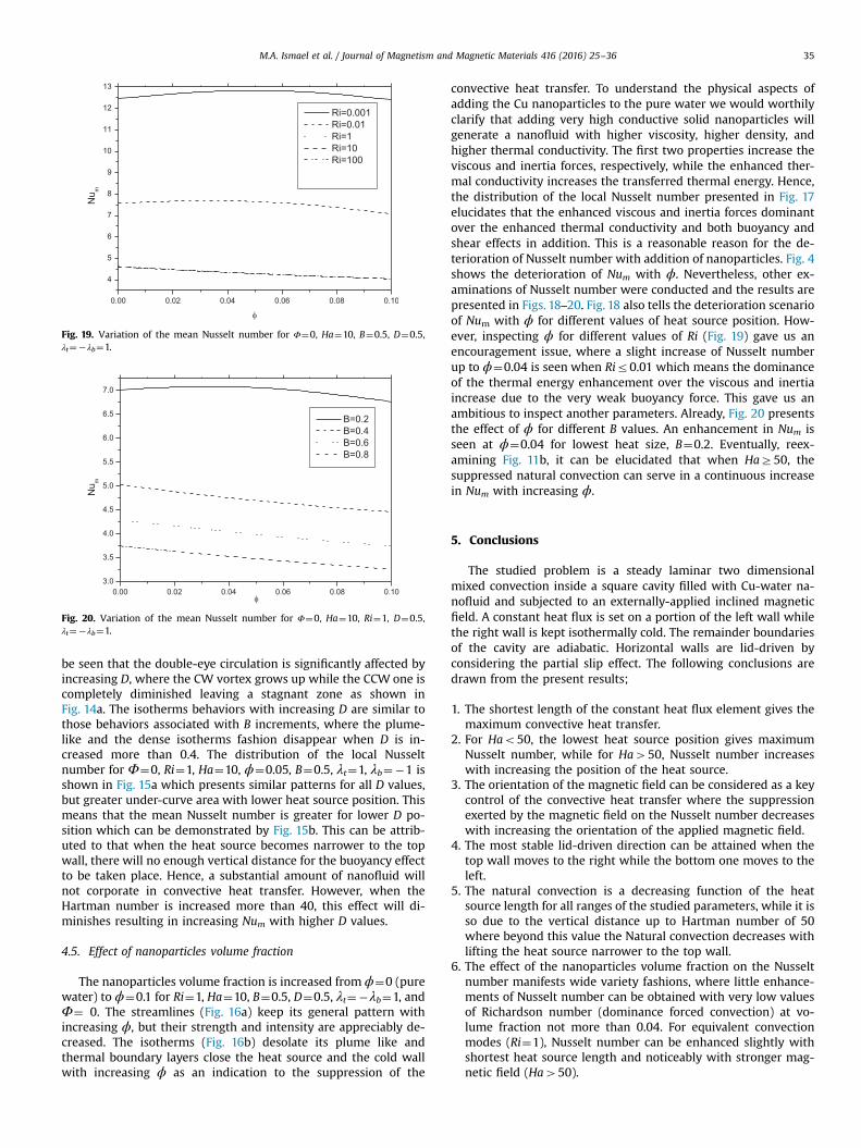
Fig. 19. Variation of the mean Nusselt number for Φ¼0, Ha¼10, B¼0.5, D¼0.5,λt¼�λb¼1.
Fig. 20. Variation of the mean Nusselt number for Φ¼0, Ha¼10, Ri¼1, D¼0.5,λt¼�λb¼1.
M.A. Ismael et al. / Journal of Magnetism and Magnetic Materials 416 (2016) 25–36 35
be seen that the double-eye circulation is significantly affected byincreasing D, where the CW vortex grows up while the CCW one iscompletely diminished leaving a stagnant zone as shown inFig. 14a. The isotherms behaviors with increasing D are similar tothose behaviors associated with B increments, where the plume-like and the dense isotherms fashion disappear when D is in-creased more than 0.4. The distribution of the local Nusseltnumber for Φ¼0, Ri¼1, Ha¼10, ϕ¼0.05, B¼0.5, λt¼1, λb¼�1 isshown in Fig. 15a which presents similar patterns for all D values,but greater under-curve area with lower heat source position. Thismeans that the mean Nusselt number is greater for lower D po-sition which can be demonstrated by Fig. 15b. This can be attrib-uted to that when the heat source becomes narrower to the topwall, there will no enough vertical distance for the buoyancy effectto be taken place. Hence, a substantial amount of nanofluid willnot corporate in convective heat transfer. However, when theHartman number is increased more than 40, this effect will di-minishes resulting in increasing Num with higher D values.
4.5. Effect of nanoparticles volume fraction
The nanoparticles volume fraction is increased from ϕ¼0 (purewater) to ϕ¼0.1 for Ri¼1, Ha¼10, B¼0.5, D¼0.5, λt¼�λb¼1, andΦ¼ 0. The streamlines (Fig. 16a) keep its general pattern withincreasing ϕ, but their strength and intensity are appreciably de-creased. The isotherms (Fig. 16b) desolate its plume like andthermal boundary layers close the heat source and the cold wallwith increasing ϕ as an indication to the suppression of the
convective heat transfer. To understand the physical aspects ofadding the Cu nanoparticles to the pure water we would worthilyclarify that adding very high conductive solid nanoparticles willgenerate a nanofluid with higher viscosity, higher density, andhigher thermal conductivity. The first two properties increase theviscous and inertia forces, respectively, while the enhanced ther-mal conductivity increases the transferred thermal energy. Hence,the distribution of the local Nusselt number presented in Fig. 17elucidates that the enhanced viscous and inertia forces dominantover the enhanced thermal conductivity and both buoyancy andshear effects in addition. This is a reasonable reason for the de-terioration of Nusselt number with addition of nanoparticles. Fig. 4shows the deterioration of Num with ϕ. Nevertheless, other ex-aminations of Nusselt number were conducted and the results arepresented in Figs. 18–20. Fig. 18 also tells the deterioration scenarioof Num with ϕ for different values of heat source position. How-ever, inspecting ϕ for different values of Ri (Fig. 19) gave us anencouragement issue, where a slight increase of Nusselt numberup to ϕ¼0.04 is seen when Rir0.01 which means the dominanceof the thermal energy enhancement over the viscous and inertiaincrease due to the very weak buoyancy force. This gave us anambitious to inspect another parameters. Already, Fig. 20 presentsthe effect of ϕ for different B values. An enhancement in Num isseen at ϕ¼0.04 for lowest heat size, B¼0.2. Eventually, reex-amining Fig. 11b, it can be elucidated that when HaZ50, thesuppressed natural convection can serve in a continuous increasein Num with increasing ϕ.
5. Conclusions
The studied problem is a steady laminar two dimensionalmixed convection inside a square cavity filled with Cu-water na-nofluid and subjected to an externally-applied inclined magneticfield. A constant heat flux is set on a portion of the left wall whilethe right wall is kept isothermally cold. The remainder boundariesof the cavity are adiabatic. Horizontal walls are lid-driven byconsidering the partial slip effect. The following conclusions aredrawn from the present results;
1. The shortest length of the constant heat flux element gives themaximum convective heat transfer.
2. For Hao50, the lowest heat source position gives maximumNusselt number, while for Ha450, Nusselt number increaseswith increasing the position of the heat source.
3. The orientation of the magnetic field can be considered as a keycontrol of the convective heat transfer where the suppressionexerted by the magnetic field on the Nusselt number decreaseswith increasing the orientation of the applied magnetic field.
4. The most stable lid-driven direction can be attained when thetop wall moves to the right while the bottom one moves to theleft.
5. The natural convection is a decreasing function of the heatsource length for all ranges of the studied parameters, while it isso due to the vertical distance up to Hartman number of 50where beyond this value the Natural convection decreases withlifting the heat source narrower to the top wall.
6. The effect of the nanoparticles volume fraction on the Nusseltnumber manifests wide variety fashions, where little enhance-ments of Nusselt number can be obtained with very low valuesof Richardson number (dominance forced convection) at vo-lume fraction not more than 0.04. For equivalent convectionmodes (Ri¼1), Nusselt number can be enhanced slightly withshortest heat source length and noticeably with stronger mag-netic field (Ha450).

M.A. Ismael et al. / Journal of Magnetism and Magnetic Materials 416 (2016) 25–3636
References
[1] J.R. Koseff, A.K. Prasad, The lid-driven cavity flow: a synthesis of quantitativeand qualitative observations, ASME J. Fluids Eng. 106 (1984) 390–398.
[2] M. Morzinski, C.O. Popiel, Laminar heat transfer in a two-dimensional cavitycovered by a moving wall, Numer. Heat. Transf. 12 (1988) 265–273.
[3] N. Ramanan, G.M. Homsy, Linear stability of lid-driven cavity flow, Phys. Fluids6 (1994) 2690–2701.
[4] R. Iwatsu, J.M. Hyun, K. Kuwahara, Mixed convection in a driven cavity with astable vertical temperature gradient, Int. J. Heat Mass Transf. 36 (1993)1601–1608.
[5] A.K. Prasad, R.J. Koseff, Combined forced and natural convection heat transferin a deep lid-driven cavity flow, Int. J. Heat Fluid Flow 17 (1996) 460–467.
[6] K. Torrance, R. Davis, K. Eike, P. Gill, D. Gutman, A. Hsui, S. Lyons, H. Zien,Cavity flows driven by buoyancy and shear, J. Fluid Mech. 51 (1972) 221–231.
[7] U. Ghia, K.N. Ghia, C.T. Shin, High-Re solutions for incompressible flow usingthe Navier-Stokes equations and a multigrid method, J. Comput. Phys. 48(1982) 367–411.
[8] A.A. Mohamad, R. Viskanta, Flow and thermal structures in a lid-driven cavityheated from below, Fluid Dyn. Res. 12 (1993) 173–184.
[9] S. Mekroussi, D. Nehari, M. Bouzit, N.S. Chemloul, Analysis of mixed convec-tion in an inclined lid-driven cavity with a wavy wall, J. Mech. Sci. Technol. 27(2013) 2181–2190.
[10] S. Sivasankaran, V. Sivakumar, A.K. Hussein, Numerical study on mixed con-vection in an inclined lid-driven cavity with discrete heating, Int. Commun.Heat Mass Transf. 46 (2013) 112–125.
[11] R.K. Tiwari, M.K. Das, Heat transfer augmentation in a two-sided lid-drivendifferentially heated square cavity utilizing nanofluids, Int. J. Heat Mass Transf.50 (2007) 2002–2018.
[12] F. Talebi, A.H. Mahmoudi, M. Shahi, Numerical study of mixed convectionflows in a square lid-driven cavity utilizing nanofluid, Int. Commun. Heat MassTransf. 47 (2010) 79–90.
[13] E. Abu-Nada, A.J. Chamkha, Mixed convection flow in a lid-driven inclinedsquare enclosure filled with a nanofluid, Eur. J. Mech. B/Fluids 29 (2010)472–482.
[14] A.J. Chamkha, E. Abu-Nada, Mixed convection flow in single- and double-liddriven square cavities filled with water–Al2O3 nanofluid: effect of viscositymodels, Eur. J. Mech. B/Fluids 36 (2012) 82–96.
[15] M. Turkyilmazoglu, MHD fluid flow and heat transfer due to a stretching ro-tating disk, Int. J. Therm. Sci. 51 (2012) 195–201.
[16] M. Sheikholeslami, M. Gorji-Bandpy, D.D. Ganji, S. Soleimani, Natural con-vection heat transfer in a cavity with sinusoidal wall filled with CuO-waternanofluid in presence of magnetic field, J. Taiwan Inst. Chem. Eng. 45 (2014)40–59.
[17] M. Sheikholeslami, M.M. Rashidi, Effect of space dependent magnetic field onfree convection of Fe3O4–water nanofluid, J. Taiwan Inst. Chem. Eng. 56 (2015)6–15.
[18] H.F. Oztop, Combined convection heat transfer in a porous lid-driven en-closure due to heater with finite length, Int. Commun. Heat Mass Transf. 33(2006) 772–779.
[19] M. Muthtamilselvan, P. Kandaswamy, J. Lee, Hydromagnetic mixed convectionin a lid-driven cavity filled with a fluid-saturated porous medium, Int. J. Appl.Math. Mech. 5 (2009) 28–44.
[20] K.M. Khanafer, A.J. Chamkha, Mixed convection flow in a lid-driven enclosurefilled with a fluid-saturated porous medium, Int. J. Heat Mass Transf. 31 (1999)1354–1370.
[21] Q. Sun, I. Pop, Free convection in a triangle cavity filled with a porous mediumsaturated with nanofluids with flush mounted heater on the wall, Int. J.Therm. Sci. 50 (2011) 2141–2153.
[22] A.J. Chamkha, M.A. Ismael, Conjugate heat transfer in a porous cavity filledwith nanofluids and heated by a triangular thick wall, Int. J. Therm. Sci. 67
(2013) 135–151.[23] G.C. Bourantas, E.D. Skouras, V.C. Loukopoulos, V.N. Burganos, Heat transfer
and natural convection of nanofluids in porous media, Eur. J. Mech. B/Fluids 43(2014) 45–56.
[24] C.Y. Wang, Flow over a surface with parallel grooves, Phys. Fluids 15 (2003)1114–1121.
[25] F. Sharipov, V. Selezniev, Data on internal rarefied gas flows, J. Phys. Chem. Ref.Data 27 (1988) 651–706.
[26] C.L.M.H. Navier, Mémoiresur les lois du movement des fluids, Mem. Acad. R.Sci. Inst. Fr. 6 (1823) 389–416.
[27] Q. He, W.-P. Wang, Numerical study of the effect of Navier slip on the drivencavity flow, J. Appl. Math. Mech. (ZAMM) 89 (2009) 857–868.
[28] T. Fang, S. Yao, J. Zhang, A. Aziz, Viscous flow over a shrinking sheet with asecond order slip flow mode, Commun. Nonlinear Sci. Numer. Simul. 15 (15)(2010) 1831–1842.
[29] A. Yoshimura, R.K. Prudhomme, Wall slip corrections for Couette and paralleldisc viscometers, J. Rheol. 32 (1988) 53–67.
[30] J. Koplik, J.R. Banavar, Corner flow in the sliding plate problem, Phys. Fluids 7(1995) 118–3125.
[31] T.Z. Qian, X.-P. Wang, Driven cavity flow: from molecular dynamics to con-tinuum hydrodynamics, SIAM Multiscale Model. Simul. 3 (2005) 749–763.
[32] X. Nie, M.O. Robbin, S. Chen, Resolving singular forces in cavity flow: multi-scale modeling from atomic to millimeter scales, Phys. Rev. Lett. 96 (2006)134501.
[33] M.A. Ismael, I. Pop, A.J. Chamkha, Mixed convection in a lid-driven squarecavity with partial slip, Int. J. Therm. Sci. 82 (2014) 47–61.
[34] F. Soltani, Ü. Yilmazer, Slip velocity and slip layer thickness in flow of con-centrated suspensions, J. Appl. Polym. Sci. 70 (1988) 515–522.
[35] M. Turkyilmazoglu, Anomalous heat transfer enhancement by slip due tonanofluids in circular concentric pipes, Int. J. Heat Mass Transf. 85 (2015)609–614.
[36] V. Malvandi, D.D. Ganji, Magnetic field and slip effects on free convectioninside a vertical enclosure filled with alumina/water nanofluid, Chem. Eng.Res. Des. 94 (2015) 55–364.
[37] F. Mabood, A. Mastroberardin, Melting heat transfer on MHD convective flowof a nanofluid over a stretching sheet with viscous dissipation and secondorder slip, J. Taiwan Inst. Chem. Eng. 57 (2015) 62–68.
[38] H.M. Elshehabey, F.M. Hady, S.E. Ahmed, R.A. Mohamed, Numerical in-vestigation for natural convection of a nanofluid in an inclined l-shaped cavityin the presence of an inclined magnetic field, Int. Commun. Heat Mass Transf.57 (2014) 228–238.
[39] S.M. Aminossadati, B. Ghasemi, Natural convection cooling of a localized heatsource at the bottom of a nanofluid-filled enclosure, Eur. J. Mech. B/Fluids 28(2009) 630–640.
[40] K. Khanafer, K. Vafai, M. Lightstone, Buoyancy-driven heat transfer enhance-ment in a two dimensional enclosure utilizing nanofluids, Int. J. Heat MassTransf. 46 (2003) 3639–3653.
[41] M. Turkyilmazoglu, A note on the correspondence between certain nanofluidflows and standard fluid flows, J. Heat Transf. 137 (2015) 024501.
[42] M. Turkyilmazoglu, Analytical solutions of single and multi-phase models forthe condensation of nanofluid film flow and heat transfer, Eur. J. Mech. B/Fluids 53 (2015) 272–277.
[43] E. Abu-Nada, A.J. Chamkha, Effect of nanofluid variable properties on naturalconvection in enclosures filled with a CuO-EG-water nanofluid, Int. J. Therm.Sci. 49 (2010) 2339–2352.
[44] J.A. Maxwell, Treatise on Electricity and Magnetism, second ed., Oxford Uni-versity Press, Cambridge, UK, 1904.
[45] H.C. Brinkman, The viscosity of concentrated suspensions and solution, J.Chem. Phys. 20 (1952) 571–581.
[46] S.V. Patankar, Numerical Heat Transfer and Fluid Flow, Hemisphere, New York,1980.