Embed Size (px)
Citation preview
J O U R N A L O F M A T E R I A L S S C I E N C E 3 9 (2 0 0 4 ) 6561 – 6569
Mechanical properties and microstructural
characterization of extrusion welds in AA6082-T4
A. LOUKUS, G. SUBHASH∗, M. IMANINEJADMechanical Engineering-Engineering Mechanics Department, Michigan TechnologicalUniversity, Houghton, MichiganE-mail: [email protected]
Microstructural observations of extrusion welds in an A-pillar made of AA6082-T4 revealed
that the observed extrusion weld is a composite of a seam weld (longitudinal weld) and a
charge weld (transverse weld). To determine the mechanical properties of this weld region,
tensile specimens were prepared with the weld located at 0◦, 45◦, and 90◦ to the tensile axis.
For comparison purposes, specimens from no-weld regions were also prepared in the
same orientations and tested. The specimens with 45◦-weld exhibited the lowest tensile
strength, followed by the specimens with 90◦-weld, no-weld and 0◦-weld specimens.
Comparison of failure strains and fracture modes revealed that weld regions are less
ductile than the no-weld regions. Microscopic observations of fractured surfaces and
further analysis revealed that Mg2Si precipitates that align along the charge weld cause
premature failure at these locations. C© 2004 Kluwer Academic Publishers
1. IntroductionExtrusion welds are an inevitable consequence of the
extrusion process. These welds are present in both
closed-loop and some open-loop cross sections. When
a heated aluminum billet is pushed into an extrusion die
cavity, the material flows around the mandrel supports
and is welded in the solid state, as shown in Fig. 1,
to form extrusion welds. Extrusion welds, as they are
broadly termed, consist of a seam weld (longitudinal
weld) and a charge weld (transverse weld) [1, 2]. Seam
welds are formed as material streams around the man-
drel supports in a porthole die and are brought into
intimate contact in the welding chamber [1]. In the in-
dustrial extrusion facilities, several billets may be ex-
truded in succession. After an extrusion cycle, some
material from the previous billet remains in the extru-
sion die ports even after the back end of the billet is cut
off. During the next cycle, the following billet pushes
the material from the previous billet through the ex-
trusion die (see Fig. 2). The resulting solid state weld-
ing between these two billet materials forms “tongue”
shaped “charge welds”, also called transverse weld. Al-
though the extrusion welds form a small fraction of the
overall volume of any extruded shape, they are some-
times responsible for premature failure of a finished
part during a forming operation [1]. This is because
failure often occurs at or near these welds thus limiting
the capability of the material to achieve more complex
shapes during forming processes. Understanding the
influence of extrusion welds on the overall mechani-
cal behavior of a component is essential because the
extrusion welds are known to affect formability, fail-
∗Author to whom all correspondence should be addressed.
ure location, fatigue life, and strength of extruded parts
in service [1–3]. This knowledge can assist in posi-
tioning mandrel supports in the porthole dies thus con-
trolling the locations of the extrusion welds in an ex-
truded part. Product design engineers can utilize such
information on extrusion welds to assess whether a
specific complex feature can be formed based on the
forming limits of the weld and no-weld regions. Die
designers can also employ this information to avoid
premature part failures at a specific location during
service. By locating weld-affected regions away from
high stressed regions of the part to be formed, they
can probably enhance the overall formability of some
alloys.
To illustrate the motivation for the current study,
a typical failure pattern of a hydroformed tube of
AA6082-T4 is shown in Fig. 3, where the seam weld
location is indicated by a dark line. Analysis of several
experiments performed by the authors also revealed that
failure does not occur exactly on the seam weld line but
occurs in the close proximity [3]. Thus, extrusion welds
could play a significant role in the formability of alu-
minum tubes since the failure location is consistently
adjacent to a weld. Therefore, the resulting formability
is for the composite material consisting of weld and
no-weld regions of an extruded tube. Since extrusion
welds are unavoidable in many extruded parts (due to
economical and manufacturing reasons), investigating
their effect on formability and failure of the material
is of considerable practical importance and is indus-
trially relevant. The additional ductility inherent in the
no-weld regions needs to be quantified (in the absence
0022–2461 C© 2004 Kluwer Academic Publishers 6561
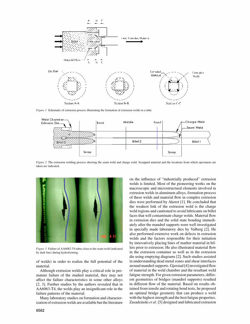
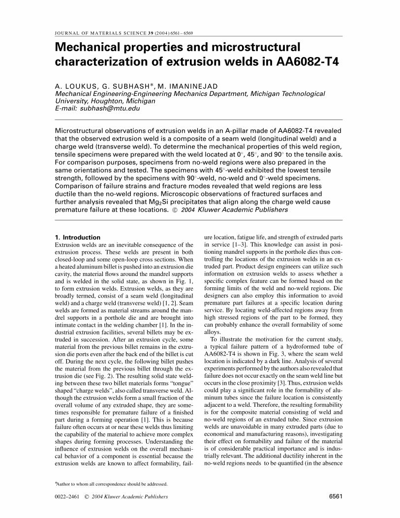
Figure 1 Schematic of extrusion process illustrating the formation of extrusion welds in a tube.
Figure 2 The extrusion welding process showing the seam weld and charge weld. Scrapped material and the locations from which specimens are
taken are indicated.
Figure 3 Failure of AA6082-T4 tubes close to the seam weld (indicated
by dark line) during hydroforming.
of welds) in order to realize the full potential of the
material.
Although extrusion welds play a critical role in pre-
mature failure of the studied material, they may not
affect the failure characteristics in some other alloys
[2, 3]. Further studies by the authors revealed that in
AA6063-T4, the welds play an insignificant role in the
failure patterns of the material.
Many laboratory studies on formation and character-
ization of extrusion welds are available but the literature
on the influence of “industrially produced” extrusion
welds is limited. Most of the pioneering works on the
macroscopic and microstructural elements involved in
extrusion welds in aluminum alloys, formation process
of these welds and material flow in complex extrusion
dies were performed by Akeret [1]. He concluded that
the weakest link of the extrusion weld is the charge
weld regions and cautioned to avoid lubricants on billet
faces that will contaminate charge welds. Material flow
in extrusion dies and the solid state bonding immedi-
ately after the mandrel supports were well investigated
in specially made laboratory dies by Valberg [2]. He
also performed extensive work on defects in extrusion
welds and the factors responsible for their initiation
by innovatively placing lines of marker material in bil-
lets prior to extrusion. He also illustrated material flow
in the extrusion container as well as in the extrusion
die using emptying diagrams [2]. Such studies assisted
in understanding dead metal zones and shear interfaces
around mandrel supports. Gjerstad [4] investigated flow
of material in the weld chamber and the resultant weld
fatigue strength. For given extrusion parameters, differ-
ent geometries of bridges (mandrel supports) resulted
in different flow of the material. Based on results ob-
tained from tensile and rotating bend tests, he proposed
an optimal bridge geometry that can produce a weld
with the highest strength and the best fatigue properties.
Zasadzinski et al. [5] designed and fabricated extrusion
6562
dies to investigate the influence of extrusion parame-
ters in producing an extrusion weld. Uni-axial tensile
tests performed along the extrusion length indicated
that the position of the extrusion weld (i.e., distance
from edge of the billet) did not affect the mechanical
properties. However, if the fracture occurred outside
the weld region, it was concluded that the extrusion
parameters were in a manner that the weld was cre-
ated successfully. Fracture occurring within the weld
region, led to the conclusion that the parameters were
not optimized to guarantee a good quality extrusion
weld. Based on these experiments, Zasadzinski et al.[5] defined optimal parameters to obtain good qual-
ity extrusion welds. Although the above experiments
were well conducted, since, the material was not in the
heat-treated condition (T4 or T6) the influence extru-
sion welds was deemed minimal in the forming process
[3].
The current research focuses on microstructural
characterization and mechanical property determina-
tion of the extrusion welds at different weld orienta-
tions from a commercially extruded, heat-treated, alu-
minum alloy. Tensile properties and ductility of the
weld-affected and no-weld regions were compared and
analyzed.
2. Specimen preparation and experimentalprocedure
Extruded “A-pillar” frames of aluminum alloy 6082-
T4 were obtained from Hydro Aluminum Technology
Center, N.A., Holland, Michigan. To identify the lo-
Figure 4 Micrographs of polished and etched A-pillar cross-section revealing the weld regions.
cation of welds on the A-pillar cross section, a small
piece was cut out from the extrusion cross-section and
was ground with 240, 320, 400 and 600 grit abrasives
successively. The entire surface was then polished with
a 6 mm diamond paste and etched initially with a 25%
NaOH + 75% water solution to locate the weld regions.
These regions were further etched with heated (∼60◦C)
NaOH solution for an additional two minutes. Obser-
vations under a stereomicroscope revealed the weld re-
gions with greater contrast. Micrographs presented in
Figs 4 and 5 illustrate the A-pillar cross-section and the
weld-affected microstructure. It is clear that each extru-
sion weld consists of two distinct zones; a central seam
weld line, surrounded by material from the previous bil-
let, shown in Fig. 2. This material is charge welded to
the new billet material on the “tongue shaped” bound-
ary [1].
Optical micrographs of this region, shown in Fig. 5a
and b, reveal that there is a distinct change in grain
size and surface topography on opposite sides of this
charge weld interface. Scanning electron microscope
(SEM) observation of this interface between the new
billet material and the previous billet material revealed
aligned precipitates along the weld boundary as seen
in Fig. 5c and d. Also, note that precipitates do exist
on both sides of this charge weld, but are randomly
distributed. More discussions on the formation of pre-
cipitates and their influence will be presented later in
this paper.
The A-pillar cross-section was ideally suited for in-
vestigation of mechanical properties of welds because
it contained one extrusion weld in the flat section (see
6563
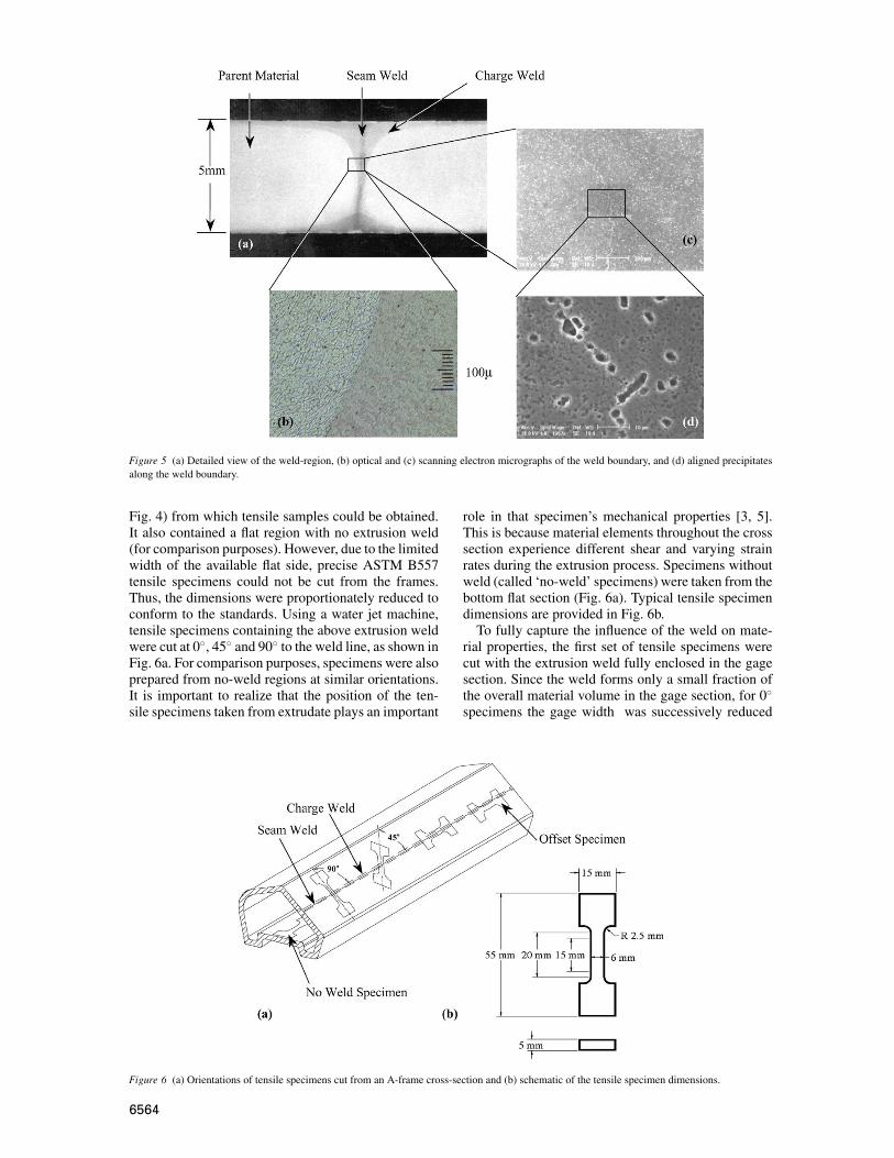
Figure 5 (a) Detailed view of the weld-region, (b) optical and (c) scanning electron micrographs of the weld boundary, and (d) aligned precipitates
along the weld boundary.
Fig. 4) from which tensile samples could be obtained.
It also contained a flat region with no extrusion weld
(for comparison purposes). However, due to the limited
width of the available flat side, precise ASTM B557
tensile specimens could not be cut from the frames.
Thus, the dimensions were proportionately reduced to
conform to the standards. Using a water jet machine,
tensile specimens containing the above extrusion weld
were cut at 0◦, 45◦ and 90◦ to the weld line, as shown in
Fig. 6a. For comparison purposes, specimens were also
prepared from no-weld regions at similar orientations.
It is important to realize that the position of the ten-
sile specimens taken from extrudate plays an important
Figure 6 (a) Orientations of tensile specimens cut from an A-frame cross-section and (b) schematic of the tensile specimen dimensions.
role in that specimen’s mechanical properties [3, 5].
This is because material elements throughout the cross
section experience different shear and varying strain
rates during the extrusion process. Specimens without
weld (called ‘no-weld’ specimens) were taken from the
bottom flat section (Fig. 6a). Typical tensile specimen
dimensions are provided in Fig. 6b.
To fully capture the influence of the weld on mate-
rial properties, the first set of tensile specimens were
cut with the extrusion weld fully enclosed in the gage
section. Since the weld forms only a small fraction of
the overall material volume in the gage section, for 0◦
specimens the gage width was successively reduced
6564
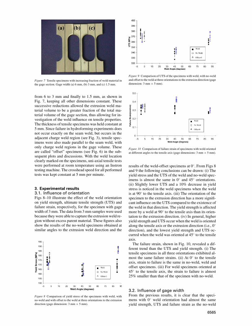
Figure 7 Tensile specimens with increasing fraction of weld material in
the gage section. Gage width (a) 6 mm, (b) 3 mm, and (c) 1.5 mm.
from 6 to 3 mm and finally to 1.5 mm, as shown in
Fig. 7, keeping all other dimensions constant. These
successive reductions allowed the extrusion weld ma-
terial volume to be a greater fraction of the total ma-
terial volume of the gage section, thus allowing for in-
vestigation of the weld influence on tensile properties.
The thickness of tensile specimens was held constant at
5 mm. Since failure in hydroforming experiments does
not occur exactly on the seam weld, but occurs in the
adjacent charge weld region (see Fig. 3), tensile spec-
imens were also made parallel to the seam weld, with
only charge weld regions in the gage volume. These
are called “offset” specimens (see Fig. 6) in the sub-
sequent plots and discussions. With the weld location
clearly marked on the specimens, uni-axial tensile tests
were performed at room temperature using an Instron
testing machine. The crosshead speed for all performed
tests was kept constant at 5 mm per minute.
3. Experimental results3.1. Influence of orientationFigs 8–10 illustrate the effect of the weld orientation
on yield strength, ultimate tensile strength (UTS) and
failure strain, respectively, for the specimen with gage
width of 3 mm. The data from 3 mm samples were used
because they were able to capture the extrusion weld re-
gion without excess parent material. These figures also
show the results of the no-weld specimens obtained at
similar angles to the extrusion weld direction and the
Figure 8 Comparison of yield stress of the specimens with weld, with
no-weld and with offset to the weld at three orientations to the extrusion
direction (gage dimension: 3 mm × 5 mm).
Figure 9 Comparison of UTS of the specimens with weld, with no-weld
and offset to the weld at three orientations to the extrusion direction (gage
dimension: 3 mm × 5 mm).
Figure 10 Comparison of failure strain of specimens with weld oriented
at different angles to the tensile axis (gage dimensions: 3 mm × 5 mm).
results of the weld-offset specimens at 0◦. From Figs 8
and 9 the following conclusions can be drawn: (i) The
yield stress and the UTS of the weld and no-weld spec-
imens is almost the same in 0◦ and 45◦ orientations.
(ii) Slightly lower UTS and a 10% decrease in yield
stress is noticed in the weld specimens when the weld
is at 90◦ to the tensile axis. (iii) The orientation of the
specimen to the extrusion direction has a more signifi-
cant influence on the UTS compared to the existence of
the weld in that direction. The yield strength is affected
more by a weld at 90◦ to the tensile axis than its orien-
tation to the extrusion direction. (iv) In general, higher
yield strength and UTS occur when the weld is oriented
along the tensile axis or the extrusion direction (i.e., 0◦
direction), and the lowest yield strength and UTS oc-
curred when the weld was oriented at 45◦ to the tensile
axis.
The failure strain, shown in Fig. 10, revealed a dif-
ferent trend than the UTS and yield strength. (i) The
tensile specimens in all three orientations exhibited al-
most the same failure strains. (ii) At 0◦ to the tensile
axis, strain to failure is the same in no-weld, weld and
offset specimens. (iii) For weld specimens oriented at
45◦ to the tensile axis, the strain to failure is almost
25% smaller than that of the specimen with no-weld.
3.2. Influence of gage widthFrom the previous results, it is clear that the speci-
mens with 0◦ weld orientation had almost the same
yield strength, UTS and failure strain as the no-weld
6565
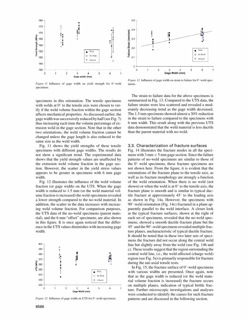
Figure 11 Influence of gage width on yield strength for 0◦-weld
specimens.
specimens in this orientation. The tensile specimens
with welds at 0◦ to the tensile axis were chosen to ver-
ify if the weld volume fraction within the gage section
affects mechanical properties. As discussed earlier, the
gage width was successively reduced by half (see Fig. 7)
thus increasing each time the volume percentage of ex-
trusion weld in the gage section. Note that in the other
two orientations, the weld volume fraction cannot be
changed unless the gage length is also reduced to the
same size as the weld width.
Fig. 11 shows the yield strengths of these tensile
specimens with different gage widths. The results do
not show a significant trend. The experimental data
shows that the yield strength values are unaffected by
the extrusion weld volume fraction in the gage sec-
tion. However, the scatter in the yield stress values
appears to be greater in specimens with 6 mm gage
width.
Fig. 12 illustrates the influence of the weld volume
fraction (or gage width) on the UTS. When the gage
width is reduced to 1.5 mm (or the weld material vol-
ume fraction is increased) the weld-specimens revealed
a lower strength compared to the no-weld material. In
addition, the scatter in the data increases with increas-
ing weld volume fraction. For comparison purposes,
the UTS data of the no-weld specimens (parent mate-
rial), and the 6 mm “offset” specimens, are also shown
in this figure. It is once again noticed that the differ-
ence in the UTS values diminishes with increasing gage
width.
Figure 12 Influence of gage width on UTS for 0◦-weld specimens.
Figure 13 Influence of gage width on strain to failure for 0◦-weld spec-
imens.
The strain to failure data for the above specimens is
summarized in Fig. 13. Compared to the UTS data, the
failure strains were less scattered and revealed a mod-
erately decreasing trend as the gage width decreased.
The 1.5 mm specimens showed almost a 30% reduction
in the strain to failure compared to the specimens with
6 mm width. This result along with the previous UTS
data demonstrated that the weld material is less ductile
than the parent material with no-weld.
3.3. Characterization of fracture surfacesFig. 14 illustrates the fracture modes in all the speci-
mens with 3 mm × 5 mm gage section. Since the failure
patterns of no-weld specimens are similar to those of
the 0◦ weld specimens, these fracture specimens are
not shown here. From the figure, it is evident that the
orientations of the fracture plane to the tensile axis, as
well as its fracture morphology are strongly a function
of the weld orientation. When there is no weld (not
shown) or when the weld is at 0◦ to the tensile axis, the
fracture plane is smooth and is similar to typical duc-
tile fracture at approximately 45◦ to the loading axis
as shown in Fig. 14a. However, the specimens with
90◦-weld orientation (Fig. 14c) fractured in a plane ap-
parently parallel to the weld interface. A closer look
at the typical fracture surfaces, shown at the right of
each set of specimens, revealed that the no-weld spec-
imens, showed a smooth ductile fracture plane but the
45◦ and the 90◦-weld specimens revealed multiple frac-
ture planes, uncharacteristic of typical ductile fracture.
It should be noted that in these two later sets of speci-
mens the fracture did not occur along the central weld
line but slightly away from the weld (see Fig. 14b and
c). These results suggest that the region surrounding the
central weld line, i.e., the weld-affected (charge weld)
region (see Fig. 5a) is primarily responsible for fracture
during the uni-axial tensile tests.
In Fig. 15, the fracture surface of 0◦-weld specimens
with various widths are presented. Once again, note
that as the gage width is reduced (or the weld mate-
rial volume fraction is increased) the fracture occurs
on multiple planes, indication of typical brittle frac-
ture. Further microscopic investigations and analyses
were conducted to identify the causes for such fracture
patterns and are discussed in the following section.
6566
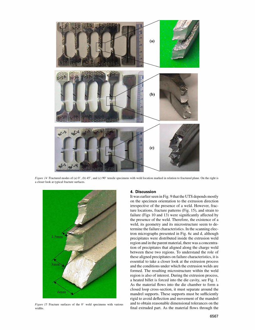
Figure 14 Fractured modes of (a) 0◦, (b) 45◦, and (c) 90◦ tensile specimens with weld location marked in relation to fractured plane. On the right is
a closer look at typical fracture surfaces.
Figure 15 Fracture surfaces of the 0◦ weld specimens with various
widths.
4. DiscussionIt was earlier seen in Fig. 9 that the UTS depends mostly
on the specimen orientation to the extrusion direction
irrespective of the presence of a weld. However, frac-
ture locations, fracture patterns (Fig. 15), and strain to
failure (Figs 10 and 13) were significantly affected by
the presence of the weld. Therefore, the existence of a
weld, its geometry and its microstructure seem to de-
termine the failure characteristics. In the scanning elec-
tron micrographs presented in Fig. 6c and d, although
precipitates were distributed inside the extrusion weld
region and in the parent material, there was a concentra-
tion of precipitates that aligned along the charge weld
between these two regions. To understand the role of
these aligned precipitates on failure characteristics, it is
essential to take a closer look at the extrusion process
and the conditions under which the extrusion welds are
formed. The resulting microstructure within the weld
region is also of interest. During the extrusion process,
a heated billet is forced into the die cavity, see Fig. 1.
As the material flows into the die chamber to form a
closed loop cross-section, it must separate around the
mandrel supports. These supports must be sufficiently
rigid to avoid deflection and movement of the mandrel
and to obtain reasonable dimensional tolerances on the
final extruded part. As the material flows through the
6567
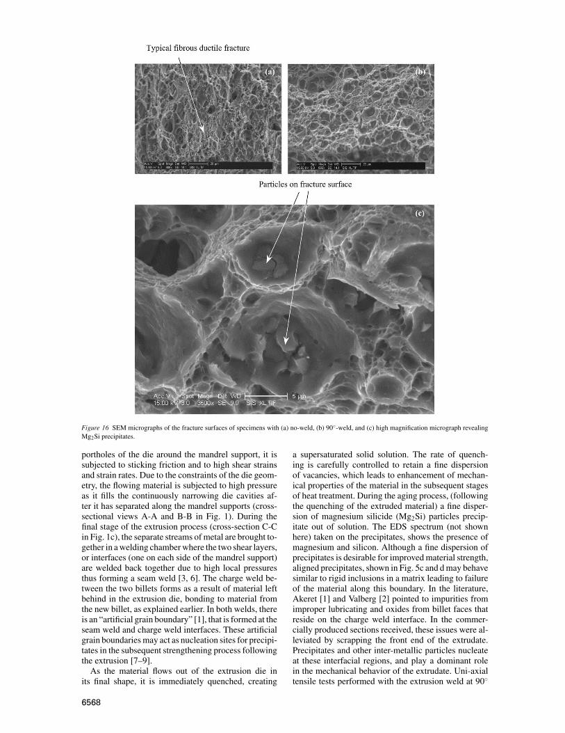
Figure 16 SEM micrographs of the fracture surfaces of specimens with (a) no-weld, (b) 90◦-weld, and (c) high magnification micrograph revealing
Mg2Si precipitates.
portholes of the die around the mandrel support, it is
subjected to sticking friction and to high shear strains
and strain rates. Due to the constraints of the die geom-
etry, the flowing material is subjected to high pressure
as it fills the continuously narrowing die cavities af-
ter it has separated along the mandrel supports (cross-
sectional views A-A and B-B in Fig. 1). During the
final stage of the extrusion process (cross-section C-C
in Fig. 1c), the separate streams of metal are brought to-
gether in a welding chamber where the two shear layers,
or interfaces (one on each side of the mandrel support)
are welded back together due to high local pressures
thus forming a seam weld [3, 6]. The charge weld be-
tween the two billets forms as a result of material left
behind in the extrusion die, bonding to material from
the new billet, as explained earlier. In both welds, there
is an “artificial grain boundary” [1], that is formed at the
seam weld and charge weld interfaces. These artificial
grain boundaries may act as nucleation sites for precipi-
tates in the subsequent strengthening process following
the extrusion [7–9].
As the material flows out of the extrusion die in
its final shape, it is immediately quenched, creating
a supersaturated solid solution. The rate of quench-
ing is carefully controlled to retain a fine dispersion
of vacancies, which leads to enhancement of mechan-
ical properties of the material in the subsequent stages
of heat treatment. During the aging process, (following
the quenching of the extruded material) a fine disper-
sion of magnesium silicide (Mg2Si) particles precip-
itate out of solution. The EDS spectrum (not shown
here) taken on the precipitates, shows the presence of
magnesium and silicon. Although a fine dispersion of
precipitates is desirable for improved material strength,
aligned precipitates, shown in Fig. 5c and d may behave
similar to rigid inclusions in a matrix leading to failure
of the material along this boundary. In the literature,
Akeret [1] and Valberg [2] pointed to impurities from
improper lubricating and oxides from billet faces that
reside on the charge weld interface. In the commer-
cially produced sections received, these issues were al-
leviated by scrapping the front end of the extrudate.
Precipitates and other inter-metallic particles nucleate
at these interfacial regions, and play a dominant role
in the mechanical behavior of the extrudate. Uni-axial
tensile tests performed with the extrusion weld at 90◦
6568
to the tensile axis show that the fracture plane is next
to this interface. The fracture runs along the interface
briefly before shearing through the rest of the material.
This would imply that the alignment of the particles
shown in Fig. 5 create a “slightly” weaker and less duc-
tile material than the surrounding matrix. These parti-
cles on this charge weld interface cause the occurrence
of more complex fracture surfaces in the weld region
compared to the smooth planar fracture of the no-weld
specimens. As discussed in the following, more parti-
cles are seen on the fracture surfaces of weld specimens
(compared to no-weld specimens) confirming that the
stress concentration due to the aligned particles initiates
the failure of the material.
To further validate the role of the Mg2Si parti-
cles discussed above on the observed fracture of the
charge weld, SEM micrographs on no-weld and 90◦-
weld specimen fracture (of 1.5 mm width) surfaces are
presented in Fig. 16. Careful observation of the mi-
crographs reveals that the 90◦-weld fracture surface
(Fig. 16b) contains a higher density of voids containing
the precipitates than the no-weld specimen fracture sur-
face shown in Fig. 16a. Also note that Fig. 16a reveals
more regions of typical ductile fracture compared to the
fracture surfaces of the material with weld in Fig. 16b.
Fig. 16c shows a high magnification picture of typical
void containing the Mg2Si precipitates. Therefore, it is
concluded that the aligned Mg2Si precipitates are par-
tially, if not primarily, responsible for the observed less
ductile behavior of the extrusion weld.
5. ConclusionsUni-axial tensile tests performed on the specimens with
extrusion welds revealed that the extrusion weld in-
fluences the fracture location, the failure characteris-
tics and the strain to failure of the extruded material.
The UTS and yield strength are moderately affected
by the weld and its orientation, but a greater reduc-
tion in ductility of the material is noticed when the
weld material volume is greatly increased in the spec-
imens. It was seen that failure occurred consistently in
the region adjacent to the seam weld, always cutting
through the charge weld interface. Microscopic obser-
vations in this region revealed a distinct change in grain
pattern (Fig. 5b) and precipitation of Mg2Si particles
along the weld/parent material interface. When speci-
mens were tested with a higher volume fraction of weld
region, the strain to failure yield strength and UTS de-
creased significantly indicating more brittle behavior of
the weld material. The failure modes were also consis-
tent with this observation. Microscopic observation of
failure surfaces revealed that the specimens with an ex-
trusion weld at 45◦ and 90◦ have more visible particles
than those without an extrusion weld.
AcknowledgementThe authors sincerely acknowledge the support from
Hydro Aluminum Technology Center N.A. in Holland,
Michigan.
References1. R . A K E R E T , in Proceedings of 5th International Aluminum Extru-
sion Technology Seminar, Chicago (1992) Vol. 1, p. 219.
2. H . V A L B E R G , Int. J. Mater. Prod. Tech. 17(7) (2002) 497.
3. H . V A L B E R G , Private Conversation, NTNU, Trondheim,
Norway, May 11, 2004.
4. O . G J E R S T A D , “Untersuchung der Eigneschaften von Langs-
pressnahten an AlMgSi1-Strangpressprofilen,” Thesis (in German),
NTNU, Trondheim, Norway, 1999.
5. J . Z A S A D Z I N S K I , J . R I C H E R T and W .M I S I O L E K , Light
Metal Age April (1993) 8.
6. P . K . S A H A , “Aluminum Extrusion Technology” (ASM Interna-
tional, Materials Park, Ohio, 2000).
7. S . S T O R E N and P . T . M O E , “Extrusion” (Handbook of Alu-
minum, Physical Metallurgy and Processes) Vol. 1, p. 385.
8. I . J . P O L M E A R , “Light Alloys—Metallurgy of the Light Alloys”
(Halsted Press, New York, 1995).
9. T . H . C O U R T N E Y , “Mechanical Behavior of Materials”
(McGraw-Hill, Boston, 2000).
Received 25 April 2003
and accepted 19 July 2004
6569