Embed Size (px)
Citation preview
Journal of Physics D Applied Physics 32, (1999), p. 1455-1461.
Influence of Beam Polarization on Laser Cutting Efficiency
V.G.Niziev, A.V.Nesterov
NICTL-Laser Research Center of Russian Academy of Sciences Shatura 140700, Russia
ABSTRACT. The 3D theory of laser cutting is presented. The cutting efficiency determined by its ultimate parameters at different types of polarization is estimated. It is shown that ultimate cutting characteristics at plane P-polarized beam are essentially worse in comparison with potential possibilities connected with P-wave absorption. The physical reasons for this limitation are illustrated. For cutting metals with a large ratio of sheet thickness to width of the cut laser cutting efficiency for radially polarized beam is 1.5-2 times more than for plane P-polarized and circularly polarized beams. The possibility of the radially polarized beam generation is discussed.
1. INTRODUCTION
Laser cutting of metals is one of the most widespread methods of laser processing. The practice
of laser cutting poses a number of basic problems. One of the most important problems is increasing
laser cutting efficiency. Laser cutting efficiency, defined as a ratio between energy expenses for
material removal and input energy, is about 20% and efficiency of the laser itself is less than 20%.
To date there exist two directions in laser cutting of metals: cutting thin sheets with a small ratio of
thickness (h) to cutting width (d) and thick sheets, for which h/d ≥ 10. For cutting thin metal sheets
they use lasers of comparatively low output power, generated in the TEM00 mode. The sharp
focusing of radiation is necessary for high-speed cutting of thin sheet steel. Frequently they use
plane polarized radiation with maximal absorption at the cut front, in comparison with the
absorption on the walls. In this case such a polarization has certain advantages.
With laser cutting of thick metal sheets, the situation is different. On the one hand, lenses of
longer focal length are used, therefore the advantage of the main mode appears less essential. On
the other hand, the use of the main mode in lasers of higher power is a difficult task to be solved.
Therefore, lasers of different transverse mode structure (TEM00/01*, TEM01*) are used.
In the case of h/d ≥ 10 the question of optimum polarization remains open until the present time.
Yet in the early study [1] the basic features of laser cutting with plane-polarized radiation were
investigated theoretically and experimentally. It was noted that the maximum efficiency of laser
cutting with plane-polarized radiation is achieved when most energy is absorbed in the front of the
cut, i.e. cutting direction is parallel to the oscillation plane of the electric field vector. But even then
many firms produced industrial lasers with the circular polarization. This tendency remains up to
now. The up-to-date technological systems for metal cutting use circularly polarized radiation,
although the plane P-polarized beam with maximum absorption on the cut front seems to be the best
for this application.
As for theoretical investigations, a great deal of them involves the particular aspects of laser
cutting such as heat diffusion at moving heat source, hydrodynamic processes, the role of oxygen,
formation of striations on the cut walls, and so on [2-7]. These authors used the simplified concepts
of radiation absorption and the cut shape.
In some studies, radiation absorption was considered in accordance with Fresnel laws. For
example, cutting with a P-polarized laser beam at the cut front was treated in [8]. The
recommendations were given for focus position and mode structure, but the influence of different
polarization types on cutting parameters was not analyzed.
The ultimate cutting depth was calculated by the use of the 3D metal cutting model [9]. The
authors used the following restrictions in calculations: energy density over the beam cross-section
was constant and peculiarities of absorption on the cut walls were not taken into account.
Another 3D laser cutting model [10] is also noteworthy. The authors considered the influence of
different parameters (intensity, polarization, focus position, mode structure, laser beam divergence)
on cutting processes. The fundamental restriction of this consideration was a simplified description
of the cut shape that was not calculated. Such an approach excludes the possibility of analyzing the
cause of restrictions on ultimate cutting parameters.
In paper [11] the 2D laser cutting task taking into account the intensity distribution according to
Gauss law and Fresnel absorption on the cut front, was solved. The front shape was found from the
stationary solution at different types of polarization and focus positions in the co-ordinate system
connected with the beam. The solution for fluctuations determined the instabilities development
area on the cut front, the velocity of fluctuation movement, along the front and the increment of
their development.
2. MATHEMATICAL MODEL
The problem of 3D cut shape description has been solved in the present study. This description
takes into account radiation absorption on the whole cut surface: both on the front and on the walls.
This approach allows comparisons of the efficiency of the action of different laser beam
polarization (plane, circular, and so on) on material from the same viewpoint.
LASER BEAM
TEM00
TEM01*
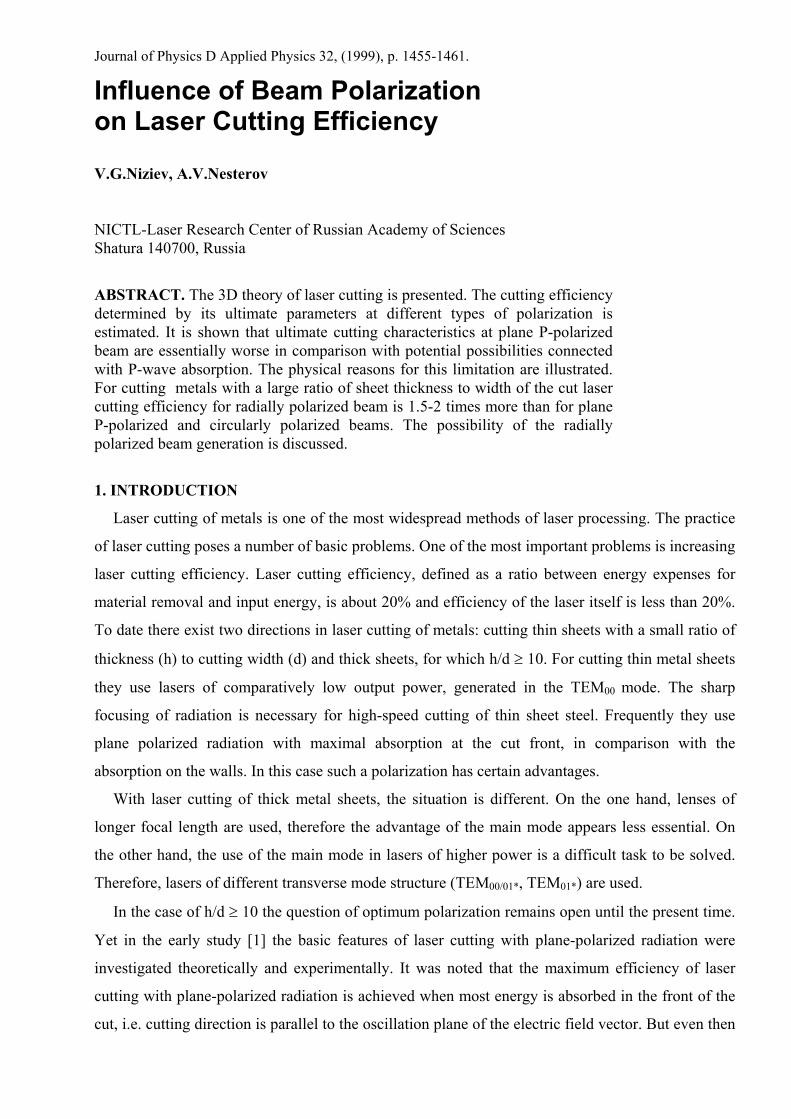
Fig. 1. The scheme of sample and laser beam positions in the used coordinate system.
Laser cutting of metal is carried out with gas jet directed at high pressure into the kerf. The main
function of gas jet is the removal of the melted material. The hydrodynamic processes are very fast
under current conditions of intense gas jet use. So the material is considered to be removed
instantly. Thus a detailed description of hydrodynamic processes becomes unnecessary.
0.1 0.1
-0.4
0
z, mm
r, mm
bb
а
c
а а
c
r, mm
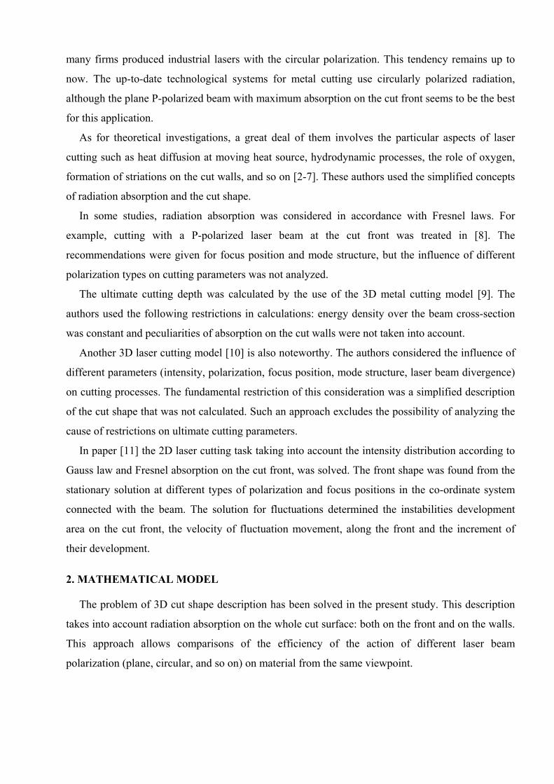
Fig. 2. Laser beam hole punching. Evolution of depth and form at azimuthal (left) and radial (right) polarization (A and R, Table 1). The curves a, b, c correspond to the time moments t1<t2<t3.
The chemical reactions on the cut surface are not discussed in the present paper. This relates
directly to laser cutting without oxygen. The problem of effective and qualitative metal cutting
without oxygen is real [12]. The aspects of radiation absorption with different polarization types
discussed in the present study are also important for cutting with oxygen.
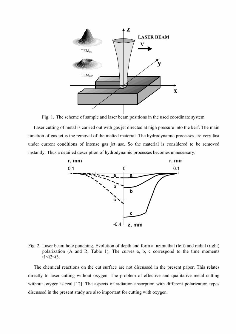
In real cutting conditions, the main portion of heat is concentrated in the melted material
removed from the kerf with gas flow. The temperature distribution is localized in the thin surface
layer. Therefore heat conduction processes are neglected in the present model.
Fig. 3. Cut form projection on y-z-plane (left) and the distribution of absorbed laser power over the cross section of the laser beam (right) for plane (P) and circular (C) polarization. Absorbed laser power is equal to I×F, see (3). The circle shows the border of a laser beam schematically, the large arrow is the direction of beam movement, the dotted line is cut contours.
The model is being considered within the limits of geometrical optics approximation. Only
single reflections have been taken into account. The cut has an open shape in comparison with the
channel at laser beam hole punching. Radiation, reflected from the laser beam action area, is
scattered on the cut walls outside this area. Thus the reflected radiation does not contribute to
material destruction and dissipates in metal by thermal conductivity.
The aspect ratio of laser cutting (the ratio of the depth to the width) is about 10 in practice. It
means that the main part of the radiation interacts with material at large angles close to the main
angle (∼85o for steel). In our model we used the classical Fresnel formulae for metals with complex
index of refraction. A significant feature of this absorption law is the sharp dependence of P-wave
absorption on large angles of incidence. Such behavior of the absorption coefficient is retained,
when the surface temperature rises. So taking into account the dependence of absorption on
temperature would not lead to qualitative changes at high temperatures up to 3000°K and can only
give some quantitative specification [13].
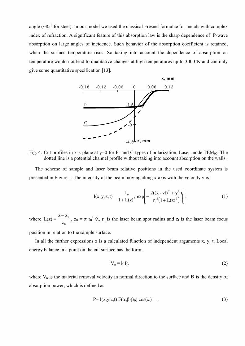
-0.18 -0.12 -0.06 0 0.06 0.12
x, mm
-4.5
-3
-1.5
z, mm
Р
С
Fig. 4. Cut profiles in x-z-plane at y=0 for P- and C-types of polarization. Laser mode TEM00. The dotted line is a potential channel profile without taking into account absorption on the walls.
The scheme of sample and laser beam relative positions in the used coordinate system is
presented in Figure 1. The intensity of the beam moving along x-axis with the velocity v is
( )I(x,y, z, t)I
1 L(z)exp
2((x - vt) y )r 1 L(z)
o2
2 2
02 2=
+−
++
, (1)
where L(z)z z
zf
0=
−, z0 = π r0
2 /λ, r0 is the laser beam spot radius and zf is the laser beam focus
position in relation to the sample surface.
In all the further expressions z is a calculated function of independent arguments x, y, t. Local
energy balance in a point on the cut surface has the form:
Vn = k P, (2)
where Vn is the material removal velocity in normal direction to the surface and Ð is the density of
absorption power, which is defined as
P= I(x,y,z,t) F(α,β-β0) cos(α) . (3)
Here F(α,β-β0) is the absorption coefficient, α is the angle of the laser beam incidence on the
surface (α= arctg z zx2
y2
= ar
+
µ
), β is the angle between the incidence plane of the laser beam and its
movement direction (β ). In the case of a plane polarized beam, the angle β0
between the electric field vector and the vector of beam velocity is constant.
ctg(z / z )y x
For a plane polarized beam F(α,β-β0) is given by the formula
FL(α,β-β0)= FS(α)sin2(β-β0)+ FP(α)cos2(β-β0), (4)
where FS(α), FP(α) are Fresnel formulae for S- and P- wave absorption. In the case of circular
polarization the absorption coefficient depends only on α:
FC(α)=(FS(α)+FP(α)) / 2. (5)
Coefficient k in (2) depends on thermal properties of the material and is a constant value. By
removal of the melted material with gas flow, k is given by:
k (c (T T ) )1 01= − + −ρ , (6)
where ñ, ρ, µ are specific heat, density and melting heat of the material; T0, T1 are the initial
temperature and the melting temperature of the material.
Because of the threshold character of material destruction, formula (2) is valid only for high
densities of absorbed power P, which exceed the threshold value. Such conditions must exist in the
beam action area where the main radiation power is contained. In particular, the use of the present
model is restricted at low beam velocity v. If the focus was on the sample surface and v was low,
the radiation intensity could decrease at high channel depth in such a way that the absorbed power
density would be below the threshold of destruction. The approximation determined by equation (2)
is fully justified for the wide spectrum of laser cutting parameters.
The equation of surface kinematic compatibility is
dN/dt=0, (7)
where N=z-z(x,y,t). Formulae (2) and (7) form an equation system that is transformed into a
nonlinear partial equation by x,y,t written in the co-ordinate system connected with the laser beam:
∂z/∂t=v ∂z/∂x - kI(x,y,z) F(α,β-β0). (8)
By analogy [11], the stationary part zs(x,y) of the general solution z(x,y,t)= zs(x,y)+δ(x,y,t)
is calculated from
v ∂ zs /∂x=kI(x,y, zs) F(α,β-β0). (9)
The stationary solution zs(x,y) defined by equation (9) exactly describes the surface under a
stable cutting regime. In real laser processing conditions convective instabilities with low amplitude
develop on the cut surface [14]. One can speak about their movement along the surface zs.
Increasing instability amplitude is restricted by time, during which the instabilities move in the
beam action area.
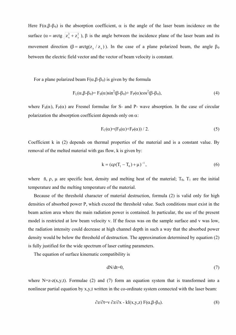
-4.5
-3
-1.5
0-0.3 -0.2 -0.1 0 0.1 0.2
x, mm
z, mm
12
3
4
Fig. 5. Cut profiles in x-z-plane at y=0 for C-polarization (curves 1, 3) and R-polarization (curves
2, 4). Ratio of beam intensity to velocity I0/v for curves 3, 4 is ten times larger than for curves 1, 2. Focus is on the sample surface. Laser mode TEM01* .
Taking into account the instabilities of the front can change the calculated results only if we
assume that the developing instabilities change the nature of absorption significantly and the
classical Fresnel formulae are not acceptable. At the present time, there is no common opinion
about the physical nature of these instabilities. No reliable data on their influence on the absorption
coefficient are available. Meanwhile, the polarization of the radiation affects the parameters of the
cut according to the S- or P-wave absorption. This universally recognized fact is indirect evidence
of the immaterial role of the front instabilities in the absorption process.
The parameters of the model are: coefficient Â=kI0/v, beam parameters r0 and z0, components of
complex refraction index of metal n(1+im) and focus position zf.
Equation (9) has been solved by the method of characteristics. Calculation of each of the specific
characteristics starts from a point on the semi-circumference having its center on the beam axis and
radius R>>r0 on the sample surface:
x2 + y2 = R2; x>0.
The following expressions are valid along the semi-circumference:
z k I x y F z z
z dx z dyx x
x y
' '
' '
( , , ) ( , )= ⋅ ⋅
⋅ + ⋅ =
0
0y'
Passing through the beam action area, the characteristics form the cut surface.
Within the framework of the present mathematical model the cut shape is described from the
sample upper surface to the ultimate depth of material removal. When the sample thickness is less
than the ultimate depth, the part of the solution that exceeds the sample thickness may not be taken
into account. The list of laser beam polarization types on which the calculations have been carried
out is given in Table 1.
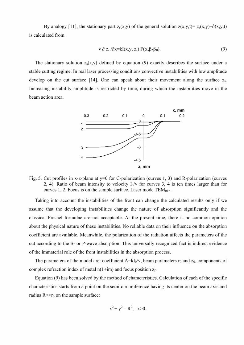
Table 1. Types of laser beam polarization used for calculation.
Laser beam polarization type
Schematic view Designation in the text
Plane polarization, an electrical vector is parallel to the beam velocity vector
P
Plane polarization, an electrical vector is perpendicular to the beam velocity vector
S
Circular polarization
C
Azimuthal polarization
A
Radial polarization
R
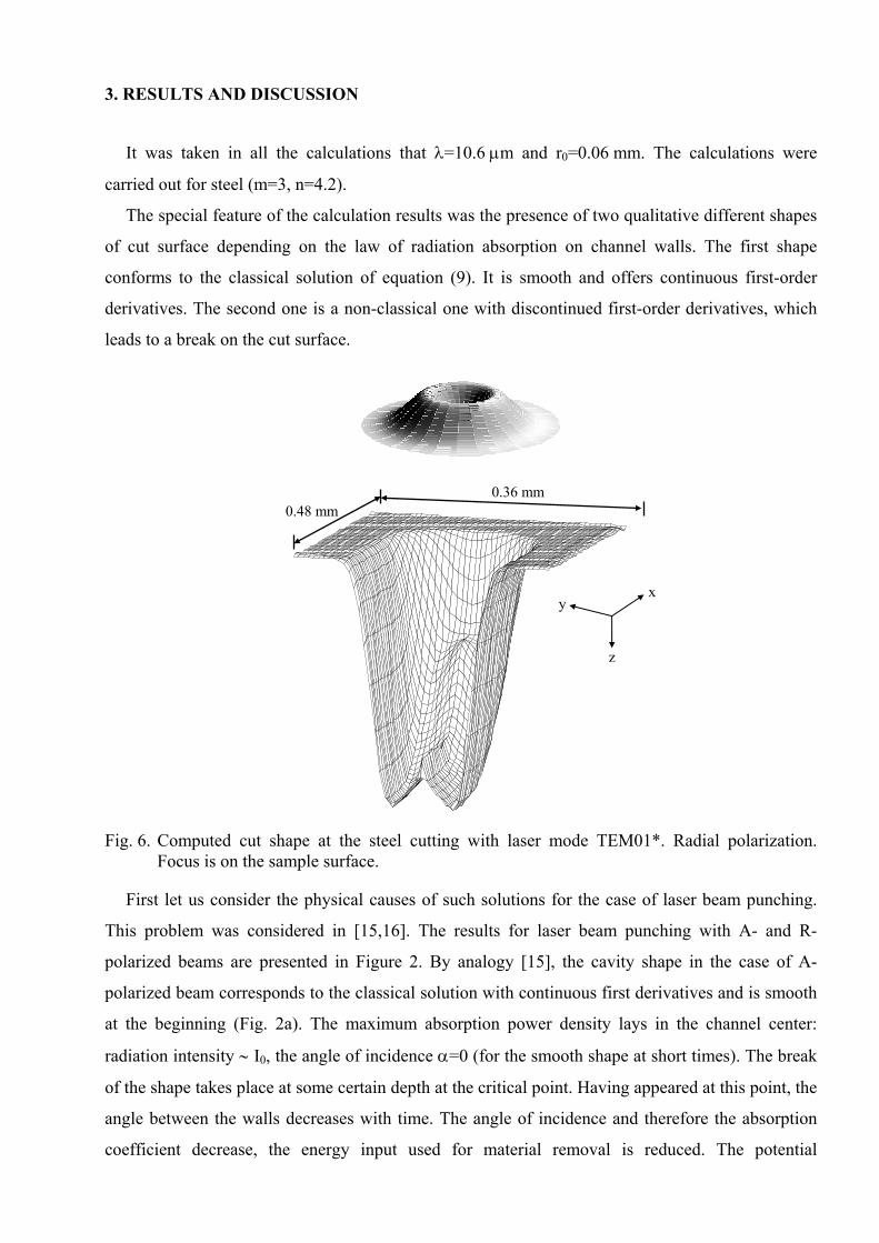
3. RESULTS AND DISCUSSION
It was taken in all the calculations that λ=10.6 µm and r0=0.06 mm. The calculations were
carried out for steel (m=3, n=4.2).
The special feature of the calculation results was the presence of two qualitative different shapes
of cut surface depending on the law of radiation absorption on channel walls. The first shape
conforms to the classical solution of equation (9). It is smooth and offers continuous first-order
derivatives. The second one is a non-classical one with discontinued first-order derivatives, which
leads to a break on the cut surface.
0.48 mm 0.36 mm
x y
z
Fig. 6. Computed cut shape at the steel cutting with laser mode TEM01*. Radial polarization. Focus is on the sample surface.
First let us consider the physical causes of such solutions for the case of laser beam punching.
This problem was considered in [15,16]. The results for laser beam punching with A- and R-
polarized beams are presented in Figure 2. By analogy [15], the cavity shape in the case of A-
polarized beam corresponds to the classical solution with continuous first derivatives and is smooth
at the beginning (Fig. 2a). The maximum absorption power density lays in the channel center:
radiation intensity ∼ I0, the angle of incidence α=0 (for the smooth shape at short times). The break
of the shape takes place at some certain depth at the critical point. Having appeared at this point, the
angle between the walls decreases with time. The angle of incidence and therefore the absorption
coefficient decrease, the energy input used for material removal is reduced. The potential
possibilities connected with the channel depth in the center by α=0 are not realized in this case. The
real depth is lower than it could be for the smooth shape with the flat bottom. Thus, one can speak
about the self-organization effect, which occurs in shape evolution to minimum radiation
absorption.
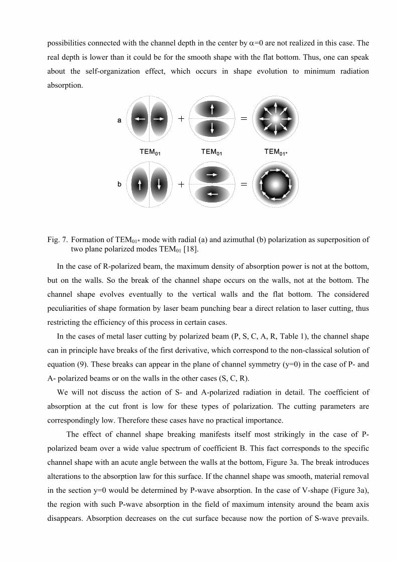
Fig. 7. Formation of TEM01* mode with radial (a) and azimuthal (b) polarization as superposition of two plane polarized modes TEM01 [18].
In the case of R-polarized beam, the maximum density of absorption power is not at the bottom,
but on the walls. So the break of the channel shape occurs on the walls, not at the bottom. The
channel shape evolves eventually to the vertical walls and the flat bottom. The considered
peculiarities of shape formation by laser beam punching bear a direct relation to laser cutting, thus
restricting the efficiency of this process in certain cases.
In the cases of metal laser cutting by polarized beam (P, S, C, A, R, Table 1), the channel shape
can in principle have breaks of the first derivative, which correspond to the non-classical solution of
equation (9). These breaks can appear in the plane of channel symmetry (y=0) in the case of P- and
A- polarized beams or on the walls in the other cases (S, C, R).
We will not discuss the action of S- and A-polarized radiation in detail. The coefficient of
absorption at the cut front is low for these types of polarization. The cutting parameters are
correspondingly low. Therefore these cases have no practical importance.
The effect of channel shape breaking manifests itself most strikingly in the case of P-
polarized beam over a wide value spectrum of coefficient B. This fact corresponds to the specific
channel shape with an acute angle between the walls at the bottom, Figure 3a. The break introduces
alterations to the absorption law for this surface. If the channel shape was smooth, material removal
in the section y=0 would be determined by P-wave absorption. In the case of V-shape (Figure 3a),
the region with such P-wave absorption in the field of maximum intensity around the beam axis
disappears. Absorption decreases on the cut surface because now the portion of S-wave prevails.
The ultimate cutting parameters become lower in comparison with the expected ones. Such a
phenomenon can be interpreted as “sticking” of the laser beam in the material between the badly
destroying channel walls. In the case presented in Figure 3a the V-shape of the channel is formed
quite fast (curve 4), so in the centre of the laser beam, the absorbed power is very low although the
intensity of radiation is maximum here. The absorption region is located in a small part of the laser
beam cross section. Naturally only this part of the beam forms the cut front. The smaller the
parameter B (it is determined in the text following (9)) taken for calculations, the bigger the
absorption area will be. So such a limitation on laser power absorption is more for the laser cutting
of thick metal sheet with big h/d.
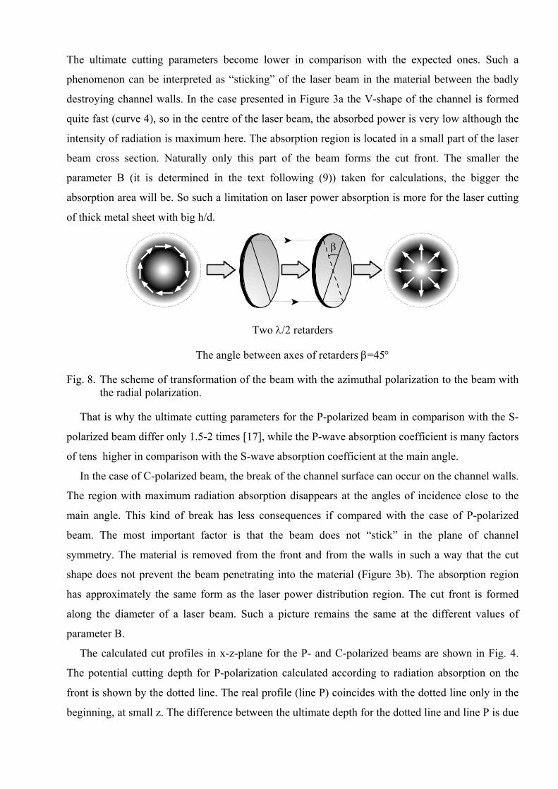
β
Two λ/2 retarders
The angle between axes of retarders β=45°
Fig. 8. The scheme of transformation of the beam with the azimuthal polarization to the beam with the radial polarization.
That is why the ultimate cutting parameters for the P-polarized beam in comparison with the S-
polarized beam differ only 1.5-2 times [17], while the P-wave absorption coefficient is many factors
of tens higher in comparison with the S-wave absorption coefficient at the main angle.
In the case of C-polarized beam, the break of the channel surface can occur on the channel walls.
The region with maximum radiation absorption disappears at the angles of incidence close to the
main angle. This kind of break has less consequences if compared with the case of P-polarized
beam. The most important factor is that the beam does not “stick” in the plane of channel
symmetry. The material is removed from the front and from the walls in such a way that the cut
shape does not prevent the beam penetrating into the material (Figure 3b). The absorption region
has approximately the same form as the laser power distribution region. The cut front is formed
along the diameter of a laser beam. Such a picture remains the same at the different values of
parameter B.
The calculated cut profiles in x-z-plane for the P- and C-polarized beams are shown in Fig. 4.
The potential cutting depth for P-polarization calculated according to radiation absorption on the
front is shown by the dotted line. The real profile (line P) coincides with the dotted line only in the
beginning, at small z. The difference between the ultimate depth for the dotted line and line P is due
to the surface evolution to the shape with minimum radiation absorption (Fig. 3a). In the case of C-
polarized beam, the front is more gentle and the ultimate cutting depth is larger. The ratio of
ultimate depth for P- and C-types of polarization can be different and depends on the slope angle of
the front and walls at specified cutting parameters. In any case the ultimate cutting parameters for
the C-polarized beam turn out not worse than for the P-polarized beam [17].
As for the laser cutting efficiency and the ultimate cutting parameters, the axis symmetrical
structure of polarization is preferable to plane P-polarization and especially to plane S-polarization.
This is so in spite of the absorption coefficient on the cut front for C-polarization which is an
average value of P- and S-wave absorption.
The preceding calculations were carried out for the laser TEM00 mode. The comparison of
cutting parameters for the R- and C-polarized beams were conducted for the laser TEM01* mode
(Fig. 5). The better cutting parameters for the R-polarized beam are easily explicable. The
coefficient of absorption is determined by P-wave absorption in the case of the R-polarized beam
and by the arithmetical mean of P- and S-wave absorption in the case of the C-polarized beam. The
ratio of ultimate depths for both the polarization types depends on parameter B, i.e., on material
properties, radiation power and beam velocity. Maximum gain owing to the advantages of material
processing with the R-polarized beam consists of increasing depth or cutting speed by 1.5-2 times
in comparison with the C-polarized beam. The presence of “shelf” on the curves (Fig..5, 6) at x∼0 is
due to the ring structure of intensity distribution in laser mode TEM01*.
Radial polarized radiation can be obtained on the basis of the laser TEM01* mode [18]. The
laser TEM01* mode is a superposition of two laser TEM01 modes turned around the beam axis by
90° relative to each other. This «doughnut» mode is circular in cross section but hollow in the
centre [19]. The resonators of the modern technological lasers commonly contain the element that
provides for the plane polarization in all the transverse modes. The radial polarized TEM01* can be
obtained only when both the laser TEM01 modes have mutually perpendicular polarization (Fig. 7a).
The generation of azimuthal polarization of the TEM01* mode is shown in Fig. 7b.
Hence, the stable radial polarization of mode TEM01* requires the specific polarization and the
appropriate phase oscillation in the TEM01 modes. The technical solutions to this problem seem to
be quite real. One of them uses a total mirror of conical form, which produces a beam with
azimuthal polarization. Azimuthal polarization can be transformed to radial polarization by means
of optical elements outside the resonator (Fig. 8). Here two phase reflecting retarders λ/2 are turned
in such a way that the angle between their axes is 45°. Then the output radiation acquires radial
polarization. There are also some possibilities to transform circular polarization into radial
polarization outside the resonator.
4. CONCLUSION
The absorption of radiation on the cutting surface is the main physical process, which determines
the cutting parameters. To adequately describe this process, the 3D problem of the cut calculation
has been solved. Within the framework of this problem the ultimate laser cutting parameters have
been estimated. A comparison of cutting efficiency for different polarization types and mode
structures has been carried out.
The significant peculiarity of the calculation results is the presence of two qualitative different
shapes of cut surface depending on the law of radiation absorption on channel walls. The first shape
is smooth and offers continuous first-order derivatives. The second has discontinued first-order
derivatives, i.e., breaks on the cut surface.
The P-polarized beam forms the shape with the break at the bottom. This V-shape results from
low radiation absorption on the cut walls. It restricts the ultimate cut depth as the area with
prevailing P-wave absorption disappears.
Such a restriction does not hold for axis-symmetrical polarization types (C, R). In these cases the
breaks of the shape can appear on the walls but not at the bottom. They do not impede the beam
penetrating into the material. The action of R- and C-polarized beams is characterized by P-wave
absorption and by the arithmetic mean of S-wave and P-wave absorption on the whole cutting
surface correspondingly. Therefore the ultimate depth and cutting speed for R-polarization are 1.5-2
times higher than the same parameters for C-polarization.
According to the calculations, C-polarized radiation is preferable to plane polarized radiation at
the TEM00 mode. R-polarized radiation is the most effective for cutting with the laser TEM01*
mode.
The physical reason for restrictions on laser cutting depth at L-polarization considered in this
paper is connected to the large difference in absorption on the front and on the walls. This takes
place at the large h/d ratio, when the angle of incidence is close to the main angle. For cutting thin
metal sheets with the small h/d ratio the increased absorption on the front in comparison with
absorption on the walls is insignificant, and the considered restrictions on the use of the Ð-polarized
radiation also become insignificant.
One of the possible methods for generating laser TEM01* mode with radial polarization includes
two steps. A laser with a conical total mirror in its resonator will generate azimuthally polarized
output radiation. It can be transformed to radial with two λ/2 retarders.
5. REFERENCES
1. F.O.Olsen ″Studies of Sheet Metal Cutting with Plane-Polarized CO2-laser″. Proc. 5th annual
Congress of Opto Electronics in Engineering (Laser-81) Munich, p.227-231, 1982.
2. G.Simon and U. Gratzke, ″Theoretical Investigations of Instabilities in Laser Gas Cutting,″ SPIE, Vol.1132, pp. 204-209, 1989
3. A.V. La Rocca, L. Rorsati and M. Cantello, ″Nozzle Design to Fluid Dynamics Effects in Laser Cutting, ″ SPIE, Vol. 2207, pp. 48-62, 1994.
4. D.Schuocker, ″Theoretical Model of Reactive Gas Assisted Laser Cutting Including Dynamic Effects″ J. Appl. Phys. B, Vol. 40, pp. 9-14, 1986.
5. M. Vicanek and G.Simon, ″Momentum and Heat Transfer of an Inert Gas Jet to the Melt in Laser Cutting,″ J.Phys. D: Appl Phys, Vol. 20, pp. 1191-1196, 1987.
6. A.F.H. Kaplan, ″An Analytical Model of Metal Cutting, ″ J.Appl.Phys., 79 (5), pp. 2198-2199, 1996.
7. A.F.H. Kaplan, O. Wangler and D. Schuocker, ″Laser Cutting: Fundamentals of the Periodic Striations and Their on-Line Direction,″ Lasers in Engineering, Vol. 2, pp. 103-126, 1997.
8. W. Schulz, G. Simon, H.M. Urbassek and I. Decker, ″On Laser Fusion Cutting,″ J.Phys. D: Appl. Phys., Vol. 20, pp. 481-488, 1986.
9. G.P. Cherepanov and A.G.Cherepanov, ″Shape and Depth at Laser Beam Cutting″, Physics and Chemistry of Material Processing (in Russian), Vol. 2, pp. 133-137, 1990.
10. D. Petring, P. Abels and E.Beyer, ″Absorption Distribution on Idealized Cutting Front Geometries and its Significance for Laser Beam Cutting,″ SPIE, Vol.1020, pp. 123-131, 1988.
11. V.G.Niziev, ″Theory of CW Laser Beam Cutting,″ Laser Physics, Vol. 3, ¹3, pp. 629-635, 1993.
12. J-M. Weick and W.Bartel, ″Laser Cutting without Oxygen and its Benefits for Cutting Stainless Steel,″ Proc. 6th Int. Conf. Lasers in Manufacturing, pp. 81-89, May 1989.
13. E.Beyer, K.Wissenbach, G.Herzinger Feinwerktechnik und Messtechnik 1984, 92, 3, S.141-143.
14. N.N. Rykalin, A.A. Uglov, I.V. Zuev and A.N. Kokora, ″Laser Material Processing″ (in Russian) Moscow, Mashinostroenie, , 496 p, 1985.
15. A.A. Vedenov, O.P. Ivanov and A.L. Chernyakov, ″Theory of Destruction of Opaque Material Surface by Laser Radiation,″ Sov. J. Quant. Electron., Vol. 14, pp. 1587-91, 1984
16. W. Schulz, G. Simon and M.Vicanek, ″Ablation of Opaque Surfaces due to Laser Irradiation, ″ J. Phys. D: Appl. Phys., Vol. 19, pp. 173-177, 1986
17. R. Nuss and S.Biermann, ″Auswirkung der Polarisation beim Laserstrahlschneiden,″ Laser und Optoelektronik, Vol. 4, pp. 389-392, 1987.
18. Handbook of Lasers with Selected Data on Optical Technology. Edited by R.J. Pressley. Chemical Rubber Co, Cleveland, 1971.
19. J. Powell, ″CO2 - Laser Cutting″, Springer Verlag, 1993, p.16.


![[Rubenchik] Physics of Laser Plasma(BookFi.org)](https://img.pdfslide.net/doc/110x75/5529f79c4a795922778b4639/rubenchik-physics-of-laser-plasmabookfiorg.jpg)