Embed Size (px)
Citation preview

JOURNAL OF RESOURCE MANAGEMENT AND TECHNOLOGY ISSN NO: 0745-6999
Vol 10, Issue1, JAN / 2019
www.jrmat.com Page No:44
Identification of Suitable Unified Power Quality Conditioner
topology for Power Quality Enhancement of Industrial Applications
P.Mahes Kumar, A.Senthil Kumar, R.Venkata Krishna
Abstract
The voltage sag, current harmonic distortions and reactive power demand are the most common problems
that affect the industrial performance. Conventionally, the UPQC with voltage source inverter topology is used to
address power quality problems. But, the topology based on conventional voltage source inverter suffers from major
disadvantages such as depends on system parameters, high transient period and limited operating conditions. To
overcome the drawbacks of the conventional inverter topology, a new neutral point clamped based UPQC topology
is proposed in this paper. The performance of the proposed UPQC topology is evaluated for various industrial loads
such as RL load and rectifier RL load. Also the effectiveness of the proposed UPQC topology is investigated for
various operating conditions extensively through SIMPOWERSYSTEM block sets of MATLAB/SIMULINK
simulation and compared with the conventional scheme.
Index Terms—Power Quality, Power Factor Improvement, Total Harmonic Distortion, UPQC strategy,
Series and Shunt Active Power Filter.
1. Introduction
The proliferation of power electronic based loads has brought great awareness on power quality of the
electrical power supply. These power electronics based loads are very sensitive and need a clean power supply for
optimal performance. In recent years, the power electronic devices are incorporated with equipments for power
conversion, measuring purposes, electronic controller has increased power quality distortion in a power transmission
and distribution system. The power electronic devices generate the unwanted current and voltage harmonics in the
power system network [1-3]. These unwanted current and voltage harmonics have caused over heating, reduced life
time, acoustic noise emission, pulsating torque in the electrical machines, malfunction of equipments and radio
interference. These effects are very expensive for the customer, ranging from minor quality variations to production
downtime. All this interest has resulted in a variety of compensation devices have developed by power engineers for
dynamic and adjustable solution to power quality problems encountered in a power distribution system.[4-6].
Traditionally, the passive filters have installed to compensate the current harmonics produced by nonlinear
load and to improve the power factor of the system. But these conventional methods have a lot of disadvantages
such as tunning problem, creates series and parallel resonance [7]&[8]. To overcome these problems, the custom
power devices are proposed. The custom power devices [7-9] provide an appropriate solution to compensate the
power quality problems and also protects the load from voltage sags, swells, outages etc. According to the topology
the custom power device is classified into the shunt active power filter, series active power filter and unified power
quality conditioner strategy. The unified power quality conditioner is the universal power conditioner for
compensating power quality problems. The unified power quality conditioner strategy is the combination of series
and shunt active power line conditioner with a common DC link capacitor.
Conventionally, the series and shunt active power filter of UPQC strategy utilizes back to back connect
three phase three leg voltage source inverter with a common DC link capacitor. The conventional topology required
high DC link capacitor voltage to mitigate the power quality problems. This problem made the control technique
more complicated and increases the rating of the system. To overcome this problem three level neutral point
clamped based voltage inverter is proposed in this paper. A number of control techniques for the UPQC strategy
have presented in the literature [14-17]. The unit vector template generation (UVTG) is a familiar time domain
based control techniques designed and analyzed in this paper. The advantage of the unit vector control technique is

JOURNAL OF RESOURCE MANAGEMENT AND TECHNOLOGY ISSN NO: 0745-6999
Vol 10, Issue1, JAN / 2019
www.jrmat.com Page No:45
that is simple to implement, easy to analyze and it has high reliability on the compensation of the power quality
problems.
In this paper, the performance of conventional and proposed UPQC topology is investigated for management of
inherent power quality issues. The implementation of sinusoidal pulse width modulation technique for proposed
UPQC strategy is discussed The power quality of a nonlinear load for before and after connecting the proposed
UPQC is investigated. The compensation of voltage sag power quality and power consumed by the load is derived
and analyzed
A general introduction to the problem of power quality is presented the in introduction, to quantify the power
quality problems, conventional distribution system is discussed in section 2, the configuration of conventional and
proposed UPQC topology for the management of inherent power quality issues are represented in section 3, the
control technique deployed in UPQC strategy for the DC link voltage regulation using a PI controller is discussed in
the section 4 and the simulation results for quantifying the benefits of proposed system is brought out in section 6,
finally the conclusions of this paper finds a place in section 7.
2. Conventional Distribution System
In conventional distribution system, the domestic loads and industrial loads are directly connected to the grid. Any
active power line conditioner is not installed between grids and loads. Such that, the three phase source voltage of
the system is given as follows
(1))tωsin(mVtsaV
(2) )ο120tωsin(mVtsbV
(3) )ο120-tωsin(mVtscV
Without any active power line conditioner, the load voltage and current is delivered from the source voltage and
current. The non linear loads created harmonic components at the point of common coupling such that the source
voltage and current contains both the fundamental and the harmonic current component is given as follows.
( ) ( ) ( ) ( ) tLV=tsV and tLI=tsI
(4) )οnφtωnsin(
∞
3,1n
nI)ο1φtωsin(1ItsI
and )tωnsin(
∞
3,1n
nV)tωsin(1VtsV
∑
∑
component lfundamenta =)ο1φ+tωsin(1I and )tωsin(1V
component harmonics = )οnφ+tωnsin(∑∞
3,1=nnI and )tωnsin(∑
∞
3,1=nnV
These harmonic components created the major power quality problems in the distribution system. A novel UPQC
strategy is introduced to mitigate the power quality problems presented in the distribution system. The compensation
capability of UPQC strategy is determined by the topologies implemented for active power filter, the following
section deals with the configuration of UPQC strategy with conventional and proposed topology.
3. Unified Power Quality Conditioner Strategy
The power quality issues gain a quantify attention in industrial sectors. In recent years for power quality
management, many compensating devices are designed by the various power engineers. Among several devices, a

JOURNAL OF RESOURCE MANAGEMENT AND TECHNOLOGY ISSN NO: 0745-6999
Vol 10, Issue1, JAN / 2019
www.jrmat.com Page No:46
unified power quality conditioner strategy is novel power device proposed to compensate the power quality
distortions in a distribution system simultaneously. The power circuit for UPQC strategy to solve power quality
problems encountered in industries and distribution system is highlighted in Fig.1. It consists of two voltage source
inverters are connected back to back which shares a common DC link. One voltage source inverter is connected in
parallel between source and load at the point of common coupling point (PCC) which forced to act as a shunt active
power filter. Another voltage source inverter is connected in series between grid and load through series transformer
acting as a series active power filter. Normally, the shunt active power filter is utilized to compensate current
harmonics created by
nonlinear loads, power factor corrections and compensate load reactive power demand. The compensation of voltage
related problems such as sag, swell, flicker, unbalance, interrupt is done by series active power filter. The
performance of shunt and series active power filter of UPQC strategy is mainly depends on its voltage source
inverter topology.
3.1 Conventional voltage source inverter topology for UPQC strategy
The impact of UPQC strategy of mitigating power problems is generally depends on the voltage source
inverter topology. The conventional voltage source inverter topology for UPQC strategy and its pulse generation
technique are shown in the Fig.2. In general, the voltage source inverter is used to generate the AC voltage from a
DC source with controlled magnitude, frequency and phase. It consists of two voltage source inverter connected
back to back with a common DC link capacitor. These inverters are forced to act as series and shunt active filter.
These active filters share a single DC link and no place for providing neutral point at the DC link. And also the
compensation of harmonics is greatly depends on passive filter. These reasons

JOURNAL OF RESOURCE MANAGEMENT AND TECHNOLOGY ISSN NO: 0745-6999
Vol 10, Issue1, JAN / 2019
www.jrmat.com Page No:47
are limited the compensation capability of the active power filter, its operating conditions and also source current
THD is quite high even after compensation. In order to overcome these problems a new voltage source inverter
topology is proposed for series and shunt active power filter.
3.2 Proposed voltage source inverter topology for UPQC strategy
The three level PWM based neutral clamped voltage source inverter topology is proposed in UPQC
strategy. The construction of the proposed topology is shown in the Fig.3. It consists of two back to back connected
three level PWM based neutral clamped voltage source inverter which sharing a common two DC link capacitor
with a neutral point. One neutral clamped voltage source inverter connected in series between source and load
through a series transformer which forced to act as series active power filter for UPQC strategy. Another neutral
clamped voltage source inverter is connected in parallel between source and load at the point of common coupling
which behave as a shunt active power filter. The advantage of the proposed topology is
two DC link capacitor is equally charged. Hence the voltage across any one of a capacitor is regulated to
compensate the power quality problems. Hence, the proposed topology reduces the power rating of filters and
JOURNAL OF RESOURCE MANAGEMENT AND TECHNOLOGY ISSN NO: 0745-6999
Vol 10, Issue1, JAN / 2019
www.jrmat.com Page No:48
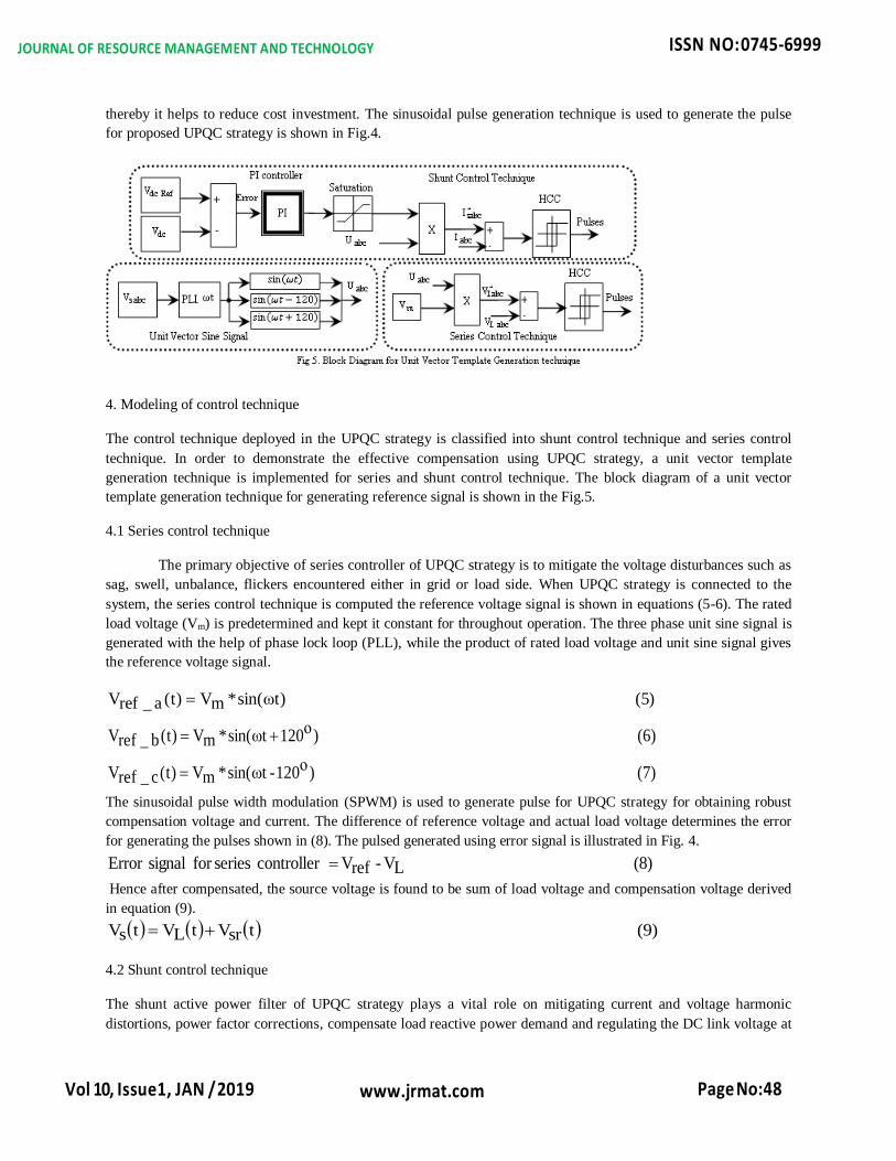
thereby it helps to reduce cost investment. The sinusoidal pulse generation technique is used to generate the pulse
for proposed UPQC strategy is shown in Fig.4.
4. Modeling of control technique
The control technique deployed in the UPQC strategy is classified into shunt control technique and series control
technique. In order to demonstrate the effective compensation using UPQC strategy, a unit vector template
generation technique is implemented for series and shunt control technique. The block diagram of a unit vector
template generation technique for generating reference signal is shown in the Fig.5.
4.1 Series control technique
The primary objective of series controller of UPQC strategy is to mitigate the voltage disturbances such as
sag, swell, unbalance, flickers encountered either in grid or load side. When UPQC strategy is connected to the
system, the series control technique is computed the reference voltage signal is shown in equations (5-6). The rated
load voltage (Vm) is predetermined and kept it constant for throughout operation. The three phase unit sine signal is
generated with the help of phase lock loop (PLL), while the product of rated load voltage and unit sine signal gives
the reference voltage signal.
(5) )tωsin(*mV)t(a_refV
(6) )ο120tωsin(*mV)t(b_refV
(7) )ο120-tωsin(*mV)t(c_refV
The sinusoidal pulse width modulation (SPWM) is used to generate pulse for UPQC strategy for obtaining robust
compensation voltage and current. The difference of reference voltage and actual load voltage determines the error
for generating the pulses shown in (8). The pulsed generated using error signal is illustrated in Fig. 4.
(8) LV - refV controller seriesfor signal Error
Hence after compensated, the source voltage is found to be sum of load voltage and compensation voltage derived
in equation (9).
(9) tsrVtLVtsV
4.2 Shunt control technique
The shunt active power filter of UPQC strategy plays a vital role on mitigating current and voltage harmonic
distortions, power factor corrections, compensate load reactive power demand and regulating the DC link voltage at

JOURNAL OF RESOURCE MANAGEMENT AND TECHNOLOGY ISSN NO: 0745-6999
Vol 10, Issue1, JAN / 2019
www.jrmat.com Page No:49
rated value. The shunt control technique is utilized PI controller for decreasing the error between actual and
reference DC link voltage and extract the reference current signal is displayed in equation (10).
(10) )tωsin(*)s
IK+p(K*)dcV-dcref(V)t(srefI
where
)sIK
+p(K is PI Controller
)dcV-dcref(V is error
)tωsin( is unit vector
The three phase reference signal for extracting compensating current is obtained as following equations
(11) )tωsin(*)dcV-dcref(V*)s
IK+p(K)t(a_srefI
(12) )ο120tωsin(*)dcV-dcref(V*)s
IK+p(K)t(b_srefI
(13) )ο120-tωsin(*)dcV-dcref(V*)s
IK+p(K)t(c_srefI
The difference of reference current and the actual source current determines error signal processed for producing the
pulses shunt active inverter shown in (14).
(14) sI - refI controller seriesfor signal Error
Hence after compensated, the source current is found to be difference of compensation current and load derived in
equation (9).
(15) tlItshItsI
5. Simulation Results, Analysis and Discussion
The performance of conventional and proposed UPQC topology is evaluated in SIMPOWERSYSTEM
block sets of MATLAB/SIMULINK of simulation software. The system ratings are taken for investigation are
230*sqrt(3/2) line to line RMS voltage, three phase RL load is 5KW+j0.1KVAR, three phase rectifier load is
20ohms and 20mH, shown in table. This investigation carried two sections: one is a comparative analysis between
conventional and proposed UPQC topology and another one is a performance analysis of the proposed strategy. In
the second section, the power quality of nonlinear loads is tested for before and after connecting proposed UPQC
strategy and also compensation of voltage sag, unbalance also carried out.

JOURNAL OF RESOURCE MANAGEMENT AND TECHNOLOGY ISSN NO: 0745-6999
Vol 10, Issue1, JAN / 2019
www.jrmat.com Page No:50
5.1 Performance Analysis of conventional and proposed UPQC topology
The regulation of DC link voltage determines the compensation capability of UPQC strategy for mitigating power
quality problems. The DC link voltage profile for conventional and proposed UPQC topology is represented in
Fig.6. the compensation of power quality by using conventional topology is done when its DC link capacitor is
charge and maintained at 550V whereas DC link voltage of proposed topology required only 260V for compensating

JOURNAL OF RESOURCE MANAGEMENT AND TECHNOLOGY ISSN NO: 0745-6999
Vol 10, Issue1, JAN / 2019
www.jrmat.com Page No:51
power quality problems. Hence, the proposed topology reduces the complexity of control technique, burdern of the
protecting device and improves the compensation capability. The peak overshoot and settling time of DC link
voltage using proposed topology is minimum compared to convention topology explained in the table. Fig. 7 shows
that the relation between DC link voltage and source current harmonic distortions using conventional and proposed
topology. This relation helps to choose the rated DC link voltage. This relation proved that the proposed UPQC
strategy has less DC link voltage. The compensation total harmonic distortion of voltage and current is illustrated in
Fig. 8. From the obtained Fig. 8, the proposed UPQC strategy has a better compensation of voltage and current
harmonic distortion.
5.2 Investigations on power quality of nonlinear load for before and after connecting proposed UPQC
strategy
In this investigation, the proposed UPQC strategy is connected to the system at 500msec shown in Fig.9. Before
500msec, the harmonics generated by the nonlinear load, is still not compensated is clearly visualized in Fig.9-A and
E. After connecting UPQC strategy, DC link voltage is regulated at rated voltage is shown in Fig.9-D. After
500msec the compensation voltage and current is starting to inject by the series and shunt active power filter. Hence
after injecting compensation voltage and current, the harmonics of source voltage and current is mitigated by the
proposed UPQC strategy
5.3 Simulation analysis for compensation of voltage sag in source side using UPQC strategy
The compensation of voltage sags conditions using proposed UPQC strategy is illustrated in the Fig. 10. In this
investigation, 20% of rated voltage is reduced in grid voltage during peak load condition at 400 msec shown in
Fig.10-A. In this state, without power line conditioner means the performance of industrial loads and domestic loads
is greatly affected. With the help of proposed UPQC strategy, the series active power filter has started to inject the
required voltage for maintaining the load voltage at rated level at the instant of 400 msec represented in Fig.10-C.
After compensated, the load voltage is maintained at rated voltage with the support of series active power filter,
Fig.10-B. Corresponding DC link voltage is also represented in the Fig.10-D. In normal operating condition, the DC
link voltage is maintained at rated value. After occurring sag conditions on the source side, the DC link voltage has
begun to reduce. The shunt active power filter has started to inject the compensation current which helps to regulate

JOURNAL OF RESOURCE MANAGEMENT AND TECHNOLOGY ISSN NO: 0745-6999
Vol 10, Issue1, JAN / 2019
www.jrmat.com Page No:52
the DC link voltage at rated value, Fig.10-G. The load current has not found to be disturbed with the help of
shunt active power filter during voltage sag condition. The fundamental magnitude of voltage is represented in
Fig.10–H for understanding the operation of UPQC strategy. This demonstration
ensured that the UPQC strategy has capable of compensating the voltage sags and maintain the load voltage at rated
value.
5.4 Simulation analysis for power consumption of load using UPQC strategy
In this section, the power consumption of the load for before and after compensation is analysed using
proposed UPQC Normally, the power consumed of the load is measured from the product of voltage and current.
However, without any power line conditioner the source current contains both the fundamental and harmonic
component and the power consumption of the nonlinear load is derived as
(16) ))nφtωnsin(
3,1nnI)1φtωsin(1I(*)tωsin(mVtsP
))nφtωnsin(
3,1nnI*)tωsin(mV
)1φtωsin(1I(*)tωcos(*)1φsin(*)tωsin(1ImV)1φcos(*)tω(2sin1ImVtsP
Power Consumed= Real power + Reactive Power + Harmonic Power
Due to the presence of harmonic and reactive power, the power consumption of the load is found to be high
for before compensation. While after connecting the UPQC strategy, the harmonic current and reactive current are
mitigated from the system such that source current is contained only fundamental component and harmonic
components are brought to zero. The power consumption of the load after compensation is measured from the
following equation.
(17) ))1φtωsin(1I(*)tωsin(mVtP
JOURNAL OF RESOURCE MANAGEMENT AND TECHNOLOGY ISSN NO: 0745-6999
Vol 10, Issue1, JAN / 2019
www.jrmat.com Page No:53
However after compensation, the voltage and current are found to be in phase with each other. The angle
between voltage and current is observed to be approximately zero, then the power equation became
(18) )1φcos(*)tω(2sin*1I*mVtsP
The power consumed as well as delivered by the UPQC strategy for maintaining the load voltage at rated
value and also compensating power quality problems is given in following equations.
The active and reactive power of series active power filter of UPQC strategy are derived as
(18) )srφcos(*sI*srVtsrP
(19) )srφsin(*sI*srVtsrQ
The active and reactive power of series active power filter of UPQC strategy are derived as
(20) )shφcos(*shI*LVtshP
(21) )shφsin(*shI*LVtshQ
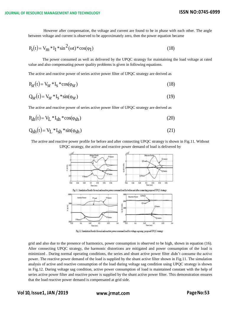
The active and reactive power profile for before and after connecting UPQC strategy is shown in Fig.11. Without
UPQC strategy, the active and reactive power demand of load is delivered by
grid and also due to the presence of harmonics, power consumption is observed to be high, shown in equation (16).
After connecting UPQC strategy, the harmonic distortions are mitigated and power consumption of the load is
minimized . During normal operating conditions, the series and shunt active power filter didn’t consume the active
power. The reactive power demand of the load is supplied by the shunt active filter shown in Fig.11. The simulation
analysis of active and reactive consumption of the load during voltage sag condition using UPQC strategy is shown
in Fig.12. During voltage sag condition, active power consumption of load is maintained constant with the help of
series active power filter and reactive power is supplied by the shunt active power filter. This demonstration ensures
that the load reactive power demand is compensated at grid side.

JOURNAL OF RESOURCE MANAGEMENT AND TECHNOLOGY ISSN NO: 0745-6999
Vol 10, Issue1, JAN / 2019
www.jrmat.com Page No:54
6. Conclusion
A neutral point clamped voltage source inverter based UPQC strategy for the management of inherent power quality
issues is proposed in this paper. The performance of the proposed UPQC strategy is outperforms the conventional
UPQC strategy for mitigation of current harmonics generated by nonlinear load. The proposed UPQC strategy has
reduced the power consumed by the nonlinear and also it helps to maintain the power factor of the system in unity.
The control strategy deployed for maintaining the load voltage at rated condition with respect to different operating
conditions is addressed. The better computational efficiency of the proposed approach has shown that it can be a
wide range of power quality problems. The dynamic simulation results have brought out the advantage of the
proposed UPQC strategy for power quality enhancement of domestic and industrial applications.
Reference
[1]. H. Akagi, “New trends in active filters for power conditioning,” IEEE Trans. Ind. Appl., vol. 32, no. 6, pp.
1312–1322, Nov.-Dec. 1996
[2]. B. Singh, K. Al-Haddad, and A. Chandra, “A review of active power filters for power quality improvement,”
IEEE Trans Ind. Electron., vol. 45, no. 5, pp. 960–971, Oct. 1999.
[3]. H. Fujita and H. Akagi, “The unified power quality conditioner: The integration of series and shunt-active
filters,” IEEE Trans. Power Electron., vol. 13, no. 1, pp. 315–322, Mar. 1998.
[4]. V. Khadkikar, A. Chandra, A. O. Barry, and T. D. Nguyen, “Application of UPQC to protect a sensitive load on
a polluted distribution network,” in Proc. IEEE PES General Meeting, Montreal, QC, Canada, 2006, 6 pp.
[5]. V. Khadkikar, A. Chandra, A. O. Barry, and T. D. Nguyen, “Conceptual analysis of unified power quality
conditioner (UPQC),” in Proc. IEEE ISIE, 2006, pp. 1088–1093.
[6]. M. Aredes, K. Heumann, and E. H.Watanabe, “An universal active power line conditioner,” IEEE Trans. Power
Del., vol. 13, no. 2, pp. 545–551, Apr. 1998.
[7]. B. Han, B. Bae, S. Baek, and G. Jang, “New configuration of UPQC for medium-voltage application,” IEEE
Trans. Power Del., vol. 21, no. 3, pp. 1438–1444, Jul. 2006.
[8]. M. Basu, S. P. Das, and G. K. Dubey, “Comparative evaluation of two models of UPQC for suitable interface to
enhance power quality,” Elect. Power Syst. Res., pp. 821–830, 2007.
[9]. K. Jindal, A. Ghosh, and A. Joshi, “Interline unified power quality conditioner,” IEEE Trans. Power Del., vol.
22, no. 1, pp. 364–372, an. 2007.
[10]. .Karuppanan P and Kamala kanta Mahapatra “PID with PLL Synchronization controlled Shunt APLC under
Non-sinusoidal and Unbalanced conditions” National Power Electronics Conference (NPEC) Proceedings, IIT-
Roorkee, June-2010.
[11]. Hirofumi Akagi and Ryota Kondo “A Transformerless Hybrid Active Filter Using a Three-Level Pulsewidth
Modulation (PWM) Converter for a Medium-Voltage Motor Drive” IEEE TRANSACTIONS ON POWER
ELECTRONICS, VOL. 25, NO. 6, JUNE 2010 1365

JOURNAL OF RESOURCE MANAGEMENT AND TECHNOLOGY ISSN NO: 0745-6999
Vol 10, Issue1, JAN / 2019
www.jrmat.com Page No:55
Appendix
System Parameter
Source
Voltage and frequency 230V and 50Hz
Impedance R=0.1Ω and L=0.1mH
DC Link
Voltage
Conventional Topology 550V
Proposed Topology 260V
Capacitor 30000µF
Shunt Active Power
Filter Impedance R=0.001Ω and L=15mH
Series Active Power
Filter
Transformer 1KVA and 1:1
Impedance R=0.001Ω and L=10mH
Load
Impedance R=0.001Ω and L=15mH
RL Load 5KW and 1KVAR
Rectifier RL Load R=20Ω and L=20mH