Embed Size (px)
Citation preview
Contents lists available at ScienceDirect
Journal of Sound and Vibration
Journal of Sound and Vibration 366 (2016) 343–356
http://d0022-46
n CorrE-m
journal homepage: www.elsevier.com/locate/jsvi
A refined one-dimensional rotordynamics modelwith three-dimensional capabilities
E. Carrera, M. Filippi n
Department of Mechanical and Aerospace Engineering, Politecnico di Torino, Corso Duca degli Abruzzi 24, 10129 Torino, Italy
a r t i c l e i n f o
Article history:Received 3 June 2015Received in revised form15 December 2015Accepted 16 December 2015
Handling Editor: H. Ouyang(LE) are here adopted to develop the refined displacement theories. The LE elements make
Available online 2 January 2016
Keywords:RotordynamicsFEMComponent-wise approachHigher-order beam theoriesCarrera Unified Formulation
x.doi.org/10.1016/j.jsv.2015.12.0360X/& 2015 Elsevier Ltd. All rights reserved.
esponding author.ail addresses: [email protected] (E. Ca
a b s t r a c t
This paper evaluates the vibration characteristics of various rotating structures. The pre-sent methodology exploits the one-dimensional Carrera Unified Formulation (1D CUF),which enables one to go beyond the kinematic assumptions of classical beam theories.According to the component-wise (CW) approach, Lagrange-like polynomial expansions
it possible to model each structural component of the rotor with an arbitrary degree ofaccuracy using either different displacement theories or localized mesh refinements.Hamilton's Principle is used to derive the governing equations, which are solved by theFinite Element Method. The CUF one-dimensional theory includes all the effects due torotation, namely the Coriolis term, spin softening and geometrical stiffening. Thenumerical simulations have been performed considering a thin ring, discs and bladed-deformable shafts. The effects of the number and the position of the blades on thedynamic stability of the rotor have been evaluated. The results have been compared, whenpossible, with the 2D and 3D solutions that are available in the literature. CUF modelsappear very practical to investigate the dynamics of complex rotating structures sincethey provide 2D and quasi-3D results, while preserving the computational effectiveness ofone-dimensional solutions.
& 2015 Elsevier Ltd. All rights reserved.
1. Introduction
The study of the dynamics of rotors is of primary importance for the design of several structural components such ascompressors, turbines, and propellers. These structures are generally analyzed through simplified mathematical models thathave been established on the basis of one- and two-dimensional assumptions.
One-dimensional models yield accurate results for rotors with compact cross-sections. For instance, using Euler–Ber-noulli and Timoshenko's beam theories, Bauer [1] and Curti et al. [2,3] analytically evaluated the critical speeds andinstabilities of metallic shafts. Bauchau [4] and Chen et al. [5] considered the same problems for thin-walled shafts made ofcomposite materials. Bert and Kim [6] compared the critical speeds of laminated cylinders with shell and experimentalresults taking into account the effect of bending–twisting coupling. In order to overcome the limitations of classical beamtheories, Song et al. [7,8] proposed refined formulations that included non-classical effects such as primary and secondarywarping effects.
rrera), [email protected] (M. Filippi).
E. Carrera, M. Filippi / Journal of Sound and Vibration 366 (2016) 343–356344
When the cross-section deformability is no longer negligible, the effect of centrifugal stiffening becomes predominant.Therefore, 2D formulations are typically adopted tomodel thin-walled structures, such as discs and cylinders. Saito and Endo [9], forinstance, used Flügge-type basic equations to evaluate the effects of different boundary conditions on the dynamics of finite-lengthrotating shells. Later, Chen et al. [10] adopted the Novoshilov theory to develop shell finite elements for vibratory problems of highspeed rotating cylinders. Similarly, Duo et al. proposed a nonlinear two-dimensional finite element to analyze thin [11] and thick[12] shells, in which the radial stress contribution was overlooked. Furthermore, Sun et al. [13] performed interesting parametricstudies using an analytical solution for any boundary condition, based on the Fourier series expansion method and the Sander shelltheory. Lam and Loy [14] evaluated the accuracy of Donnell, Flügge, Love and Sanders shell theories for simply supported laminatedcylinders through a unified formulation. In [15], the authors considered different boundary conditions using the most efficienttheory for thin cylinders, namely the Love theory. The same displacement formulationwas used in [16], where Lee and Kim studiedthe dynamic behavior of orthotropic cylinders with axial and circumferential stiffeners. Considering the Reissner–Mindlin kine-matical hypothesis, Chatelet et al. [18] proposed reduction techniques for dynamic analyses of cyclically symmetric multilayeredstructures such as cylinders and disc-shaft assemblies.
On the other hand, several rotor configurations have been modeled through combinations of one-, two- and three-dimensionalapproaches. For instance, Jang and Lee [19] combined the FEM with substructure synthesis to describe the dynamic behavior of aspinning disc-spindle system. The disc was modeled using 2D elements based on the Kirchhoff theory, while the spindle andstationary were discretized using Rayleigh and Euler beam elements, respectively. Later, Jang and Han [20] extended this approachto a disc-spindle system supported by flexible structures, such as a stator core, housing and base plate. The supports were modeledwith three-dimensional elements to ensure the fulfilment of geometric compatibility with the beam elements. Genta et al. [21]developed an annular element to describe the dynamics of rotating bladed discs on flexible shafts. The structural components(shaft, disc and blades) were linked using “transition” elements. The displacement field for the disc was obtained using a Fourierseries and polynomial shape functions along the circumferential and radial direction, respectively. Combescure and Lazarus [22]combined 2D Fourier elements with 3D FE to perform analyses of large rotating machines. The main limitation of the Fourierapproach is that the rotors must be axisymmetric. Therefore, in order to study asymmetric structures and ensure an accuratedescription of their kinematics, the 3D FE modeling techniques are often used [23]. Despite the significant advances in computingpower, large and sophisticated 3D models still represent complex computational problems. These problems have driven thederivation of reducing techniques, which are commonly found in the control, optimization, and structural mechanics fields,especially over the last few years. A reduction model, in a nutshell, is a mathematical tool that is devoted to limiting the number ofcomputations, starting from information obtained from computationally expensive 3D models [24]. As far as computing efficiencyis concerned, the benefits of these approaches are significant but their use generally requires great capabilities in the interpretationof the physical system in order to preserve the characteristics of the real structure. An interesting review on reduction models canbe found in [25].
The present paper presents a class of refined one-dimensional beam models obtained through the Carrera Unified Formulation[26]. CUF enables one, at least theoretically, to derive an infinite number of sophisticated displacement models. As far as the rotordynamics problem is concerned, the 1D-CUF approach has led to encouraging results for shafts made of isotropic [27] andorthotropic materials [28] and for thin/thick rotating shells [29]. In these works, Taylor-like expansions of n-th order (TEn) wereadopted to obtain the displacement theories. The results have demonstrated that TE models are efficient for prismatic structures,but they can show limitations when the components of the rotor present different deformability. In order to overcome thisshortcoming, the CWmethod has been extended, for the first time, within the CUF framework, to the rotordynamics problem. TheCW approach exploits the inherent capability of Lagrange-type expansions (LE) to assemble CUF beam models at the cross-sectionlevel. The CW methodology allows only beam elements to be used to model each component of the rotor (shaft, disc, blade, etc.)with arbitrary kinematic assumptions, which depend on the characteristics of the components (deformability, mechanical prop-erties, etc.). Moreover, only physical surfaces are employed to build the mathematical model. The enhanced capabilities of the CW-CUF approach have already been observed in static and dynamic analyses of aeronautical, civil and composite structures. Theproposed formulation includes all the effects due to the rotation, namely the Coriolis, spin softening and stress stiffening con-tribution. Numerical analyses have been carried out on both axisymmetric and asymmetric rotating structures, and the relatedresults have been compared with solutions available in the literature and with those obtained by means of an FE commercialsoftware. The article is organized as follows. Section 2 presents the basic notions of the LE formulation; Section 3 contains therotordynamics equations in CUF form; Section 4 is devoted to the numerical results, and the concluding remarks are given inSection 5.
2. One-dimensional theories through the unified formulation: the Lagrange element
Within the CUF framework, the displacement field is an expansion of generic cross-sectional functions, Fτ:
uðx; y; zÞ ¼ Fτðx; zÞuτðyÞ τ¼ 1;2;…;M (1)
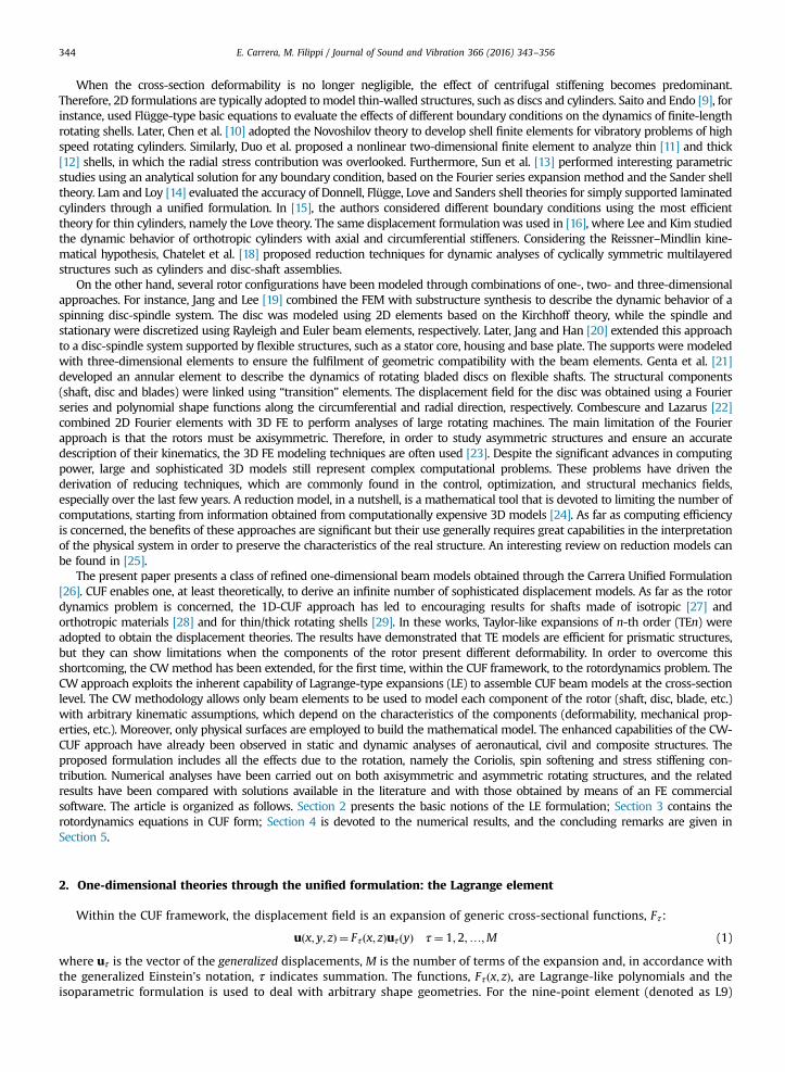
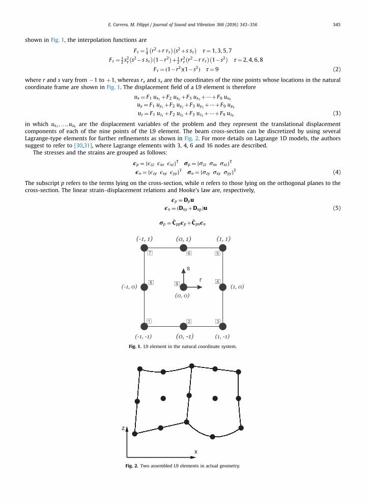
where uτ is the vector of the generalized displacements, M is the number of terms of the expansion and, in accordance withthe generalized Einstein's notation, τ indicates summation. The functions, Fτðx; zÞ, are Lagrange-like polynomials and theisoparametric formulation is used to deal with arbitrary shape geometries. For the nine-point element (denoted as L9)
E. Carrera, M. Filippi / Journal of Sound and Vibration 366 (2016) 343–356 345
shown in Fig. 1, the interpolation functions are
Fτ ¼ 14 r2þr rτ� �
s2þs sτ� �
τ¼ 1;3;5;7
Fτ ¼ 12 s
2τ s2�s sτ� �
1�r2� �þ1
2 r2τ r2�r rτ� �
1�s2� �
τ¼ 2;4;6;8
Fτ ¼ ð1�r2Þð1�s2Þ τ¼ 9 (2)
where r and s vary from �1 to þ1, whereas rτ and sτ are the coordinates of the nine points whose locations in the naturalcoordinate frame are shown in Fig. 1. The displacement field of a L9 element is therefore
ux ¼ F1 ux1 þF2 ux2 þF3 ux3 þ⋯þF9 ux9
uy ¼ F1 uy1 þF2 uy2 þF3 uy3 þ⋯þF9 uy9
uz ¼ F1 uz1 þF2 uz2 þF3 uz3 þ⋯þF9 uz9 (3)
in which ux1 ;…;uz9 are the displacement variables of the problem and they represent the translational displacementcomponents of each of the nine points of the L9 element. The beam cross-section can be discretized by using severalLagrange-type elements for further refinements as shown in Fig. 2. For more details on Lagrange 1D models, the authorssuggest to refer to [30,31], where Lagrange elements with 3, 4, 6 and 16 nodes are described.
The stresses and the strains are grouped as follows:
ϵp ¼ fϵzz ϵxx ϵxzgT σp ¼ fσzz σxx σxzgTϵn ¼ fϵzy ϵxy ϵyygT σn ¼ fσzy σxy σyygT (4)
The subscript p refers to the terms lying on the cross-section, while n refers to those lying on the orthogonal planes to thecross-section. The linear strain–displacement relations and Hooke's law are, respectively,
ϵp ¼Dpuϵn ¼ ðDnyþDnpÞu (5)
σp ¼ ~Cppϵpþ ~Cpnϵn
Fig. 1. L9 element in the natural coordinate system.
Fig. 2. Two assembled L9 elements in actual geometry.
E. Carrera, M. Filippi / Journal of Sound and Vibration 366 (2016) 343–356346
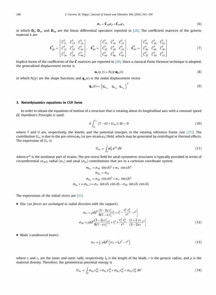
σn ¼ ~Cnpϵpþ ~Cnnϵn (6)
in which Dp, Dny and Dnp are the linear differential operators reported in [26]. The coefficient matrices of the genericmaterial k are
~Ckpp ¼
~Ck11
~Ck12
~Ck14
~Ck12
~Ck22
~Ck24
~Ck14
~Ck24
~Ck44
26664
37775; ~C
kpn ¼
~Ck15
~Ck16
~Ck13
~Ck25
~Ck26
~Ck23
~Ck45
~Ck46
~Ck43
26664
37775; ~C
knn ¼
~Ck55
~Ck56
~Ck35
~Ck56
~Ck66
~Ck36
~Ck35
~Ck36
~Ck33
26664
37775 (7)
Explicit forms of the coefficients of the ~C matrices are reported in [28]. Since a classical Finite Element technique is adopted,the generalized displacement vector is
uτðy; tÞ ¼NiðyÞqτiðtÞ (8)
in which Ni(y) are the shape functions and qτiðtÞ is the nodal displacement vector
qτiðtÞ ¼ quxτiquyτi
quzτi
n oT(9)
3. Rotordynamics equations in CUF form
In order to obtain the equations of motion of a structure that is rotating about its longitudinal axis with a constant speedΩ, Hamilton's Principle is used:
δZ t1
t0T�ðUþUσ0 Þ� �
dt ¼ 0 (10)
where T and U are, respectively, the kinetic and the potential energies in the rotating reference frame (see [27]). Thecontribution Uσ0 is due to the pre-stress σ0 (or pre-strain ϵ0) field, which may be generated by centrifugal or thermal effects.The expression of Uσ is
Uσ0 ¼ZVσT0 ϵ
nl dV (11)
where ϵnl is the nonlinear part of strains. The pre-stress field for axial-symmetric structures is typically provided in terms ofcircumferential ðσδδÞ, radial (σrr) and axial (σyy) contributions that are in a cartesian coordinate system
σ0xx ¼ σδδ sin ðδÞ2þσrr cos ðδÞ2σ0yy ¼ σyy
σ0zz ¼ σδδ cos ðδÞ2þσrr sin ðδÞ2
σ0xz ð ¼ σ0zx Þ ¼ σrr sin ðδÞ cos ðδÞ�σδδ sin ðδÞ cos ðδÞ
The expressions of the initial stress are [23]
� Disc (no forces are exchanged in radial direction with the support):
σrr ¼ ρΩ2 ð3�2νÞ8ð1�νÞ r2oþr2i �
r2i r2o
r2�r2
� �
σδδ ¼ ρΩ2ð3�2νÞ8ð1�νÞ r2oþr2i þ
r2i r2o
r2�ð1þ2 νÞ
ð3�2νÞ r2
� �(12)
� Blade (cantilevered beam):
σrr ¼ 12 ρΩ2 ðroþ lbÞ2�r2
� �(13)
where ri and ro are the inner and outer radii, respectively, lb is the length of the blade, r is the generic radius, and ρ is thematerial density. Therefore, the geometrical potential energy is
Uσ0 ¼ZVσ0xxϵ
nlxxþσ0zzϵ
nlzzþσ0xzϵ
nlxzþσ0zxϵ
nlzx dV (14)
E. Carrera, M. Filippi / Journal of Sound and Vibration 366 (2016) 343–356 347
Using Eqs. (1) and (8), Eq. (10) becomesZ t1
t0δqT
τiMijτs €qsjþδqT
τiGijτsΩ
_qsjþδqTτi KijτsþKijτs
σ0�Kijτs
Ω
� �qsjþδqT
τi½FiτΩr� �
dt ¼ 0 (15)
The matrices written in terms of fundamental nuclei are
Mijτs ¼ Iijl ◁ðFτρkIFsÞ▷GijτsΩ ¼ Iijl ◁ðFτρkIFsÞ▷2Ω
Kijτs ¼ Iijl ◁DTnpðFτIÞ ~C
knpDpðFsIÞþ ~C
knnDnpðFsIÞ
h iþDT
pðFτIÞ ~CkppDpðFsIÞþ ~C
kpnDnpðFsIÞ
h i▷þ Iij;yl ◁ DT
npðFτIÞþDTpðFτIÞ ~C
kpn
h iFs▷
þ Ii;yjl ITAy◁Fτ ~CknpDpðFsIÞþ ~C
knnDnpðFsIÞ
h i▷þ Ii;yj;yl ITAyIAy◁Fτ ~C
knnFs▷
Kijτsσ0
¼ Iijl ◁ðFτ;xσ0xx IFs;x ÞþðFτ;zσ0zz IFs;z ÞþðFτ;xσ0xz IFs;z ÞþðFτ;zσ0zx IFs;x Þ▷KijτsΩ ¼ Iijl ◁ðFτρkIFsÞ▷ΩTΩFiτΩ ¼ Iil◁Fτρr▷Ω
TΩ (16)
where
Ω¼0 0 Ω0 0 0
�Ω 0 0
264
375 IAy ¼
0 0 11 0 00 1 0
264
375 I¼
1 0 00 1 00 0 1
264
375 (17)
◁… ▷¼ZA… dA (18)
Iil; Iijl ; I
ij;yl ; Ii;yjl ; Ii;yj;yl
� �¼Zl
Ni;Ni Nj; Ni Nj;y ; Ni;y Nj; Ni;y Nj;y
� �dy (19)
and r¼ fxP ;0; zPgT is the distance of a generic point P belonging to the cross-section from the neutral axis. The ninecomponents of the fundamental nucleus of the matrix Kijτs are written in an explicit form in [28].
The homogeneous equations are solved assuming a periodic solution q¼ qeiωt in order to obtain natural frequencies andnormal modes of the rotor:
qeiωt KþKσ0 �KΩ� �þðGΩÞiω�ðMÞω2� ¼ 0 (20)
The quadratic eigenvalue problem of Eq. (20) is solved as previously done in [27,28].
4. Numerical results
This section has the aim of showing how various rotors can be modeled using only the 1D-CUF approach. In order todemonstrate the enhanced features of LE models, highly deformable structures have been considered, in which the effects due torotation can only be predicted properly using 2D and 3D approaches.
Table 1Frequencies (Hz) of the ring shown in Fig. 3.
Mode 7,8a 9,10b 11,12a 13,14a 15,16b 17,18a 19,20b DOF
40L91B3 51.46 94.92 145.9 280.8 300.7 456.1 605.9 21602B3 51.46 92.52 145.9 280.8 295.5 456.1 598.0 36003B3 51.46 92.11 145.9 280.8 294.6 456.0 596.7 50404B3 51.46 91.99 145.9 280.7 294.4 456.0 596.3 64805B3 51.46 91.94 145.9 280.7 294.3 456.0 596.3 7920
20L161B3 50.79 94.13 143.7 275.9 298.7 447.2 602.2 21602B3 50.78 91.67 143.7 275.9 293.3 447.2 593.9 36003B3 50.78 91.29 143.7 275.9 292.5 447.2 592.8 50404B3 50.78 91.18 143.7 275.9 292.3 447.2 592.4 64805B3 50.78 91.14 143.7 275.9 292.2 447.2 592.3 7920HEXA8c 50.64 94.43 143.8 275.8 298.3 446.5 599.6 2160HEXA20c 50.80 91.06 143.0 273.7 291.3 441.5 589.3 7200
a In-plane mode.b Out-of-plane mode.c 80�2�2 brick finite elements.
E. Carrera, M. Filippi / Journal of Sound and Vibration 366 (2016) 343–356348
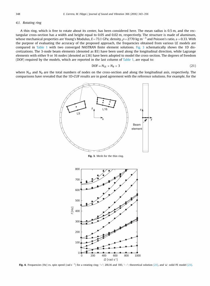
4.1. Rotating ring
A thin ring, which is free to rotate about its center, has been considered here. The mean radius is 0.5 m, and the rec-tangular cross-section has a width and height equal to 0.05 and 0.02 m, respectively. The structure is made of aluminum,whose mechanical properties are Young's Modulus, E¼73.1 GPa; density, ρ¼2770 kg m�3 and Poisson's ratio, ν¼0.33. Withthe purpose of evaluating the accuracy of the proposed approach, the frequencies obtained from various LE models arecompared in Table 1 with two converged NASTRAN finite element solutions. Fig. 3 schematically shows the 1D dis-cretizations. The 3-node beam elements (denoted as B3) have been used along the longitudinal direction, while Lagrangeelements with either 9 or 16 nodes (denoted as L16) have been adopted to model the cross-section. The degrees of freedom(DOF) required by the models, which are reported in the last column of Table 1, are equal to:
DOF¼NLE � NB � 3 (21)
where NLE and NB are the total numbers of nodes on the cross-section and along the longitudinal axis, respectively. Thecomparisons have revealed that the 1D-CUF results are in good agreement with the reference solutions. For example, for the
Fig. 3. Mesh for the thin ring.
Fig. 4. Frequencies (Hz) vs. spin speed (rad s�1) for a rotating ring; ‘—’: 20L16 and 1B3, ‘- -’: theoretical solution [23], and ‘�’: solid FE model [23].
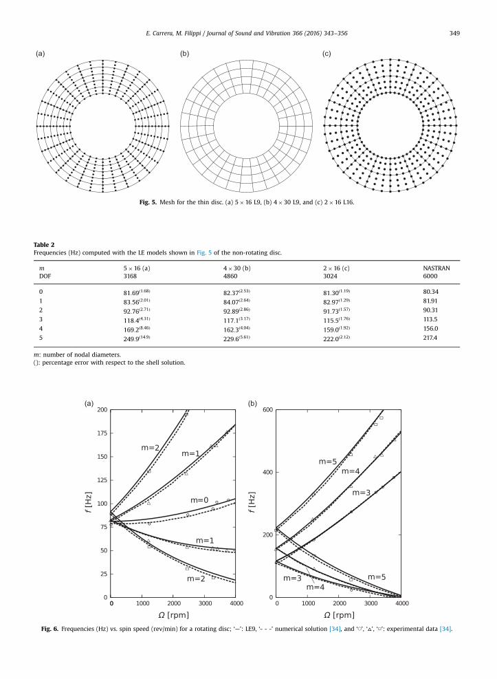
Fig. 5. Mesh for the thin disc. (a) 5�16 L9, (b) 4�30 L9, and (c) 2�16 L16.
Table 2Frequencies (Hz) computed with the LE models shown in Fig. 5 of the non-rotating disc.
m 5�16 (a) 4�30 (b) 2�16 (c) NASTRANDOF 3168 4860 3024 6000
0 81:69ð1:68Þ 82:37ð2:53Þ 81:30ð1:19Þ 80.34
1 83:56ð2:01Þ 84:07ð2:64Þ 82:97ð1:29Þ 81.91
2 92:76ð2:71Þ 92:89ð2:86Þ 91:73ð1:57Þ 90.31
3 118:4ð4:31Þ 117:1ð3:17Þ 115:5ð1:76Þ 113.5
4 169:2ð8:46Þ 162:3ð4:04Þ 159:0ð1:92Þ 156.0
5 249:9ð14:9Þ 229:6ð5:61Þ 222:0ð2:12Þ 217.4
m: number of nodal diameters.(): percentage error with respect to the shell solution.
Fig. 6. Frequencies (Hz) vs. spin speed (rev/min) for a rotating disc; ‘—’: LE9, ‘- - -’ numerical solution [34], and ‘◯’, ‘▵’, ‘□’: experimental data [34].
E. Carrera, M. Filippi / Journal of Sound and Vibration 366 (2016) 343–356 349
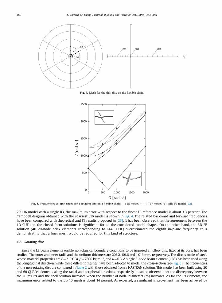
Fig. 7. Mesh for the thin disc on the flexible shaft.
Fig. 8. Frequencies vs. spin speed for a rotating disc on a flexible shaft; ‘—’: LE model, ‘- - -’: TE7 model, ‘�’: solid FE model [22].
E. Carrera, M. Filippi / Journal of Sound and Vibration 366 (2016) 343–356350
20 L16 model with a single B3, the maximum error with respect to the finest FE reference model is about 3.3 percent. TheCampbell diagram obtained with the coarsest L16 model is shown in Fig. 4. The related backward and forward frequencieshave been compared with theoretical and FE results proposed in [23]. It has been observed that the agreement between the1D-CUF and the closed-form solutions is significant for all the considered modal shapes. On the other hand, the 3D FEsolution (40 20-node brick elements corresponding to 1440 DOF) overestimated the eighth in-plane frequency, thusdemonstrating that a finer mesh would be required for this kind of structure.
4.2. Rotating disc
Since the LE beam elements enable non-classical boundary conditions to be imposed a hollow disc, fixed at its bore, has beenstudied. The outer and inner radii, and the uniform thickness are 203.2, 101.6 and 1.016 mm, respectively. The disc is made of steel,whose material properties are E¼210 GPa, ρ¼7800 kgm�3, and ν¼0.3. A single 3-node beam element (1B3) has been used alongthe longitudinal direction, while three different meshes have been adopted to model the cross-section (see Fig. 5). The frequenciesof the non-rotating disc are compared in Table 2 with those obtained from a NASTRAN solution. This model has been built using 20and 60 QUAD4 elements along the radial and peripheral directions, respectively. It can be observed that the discrepancy betweenthe LE results and the shell solution increases when the number of nodal diameters (m) increases. As for the L9 elements, themaximum error related to the 5�16 mesh is about 14 percent. As expected, a significant improvement has been achieved by
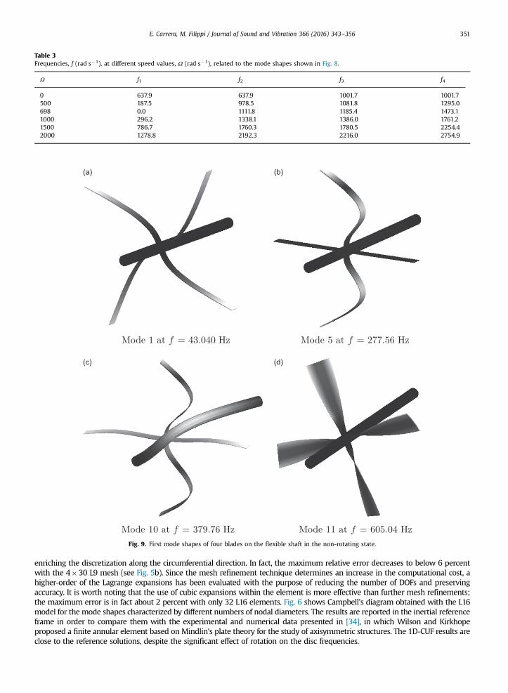
Table 3Frequencies, f (rad s�1), at different speed values, Ω (rad s�1), related to the mode shapes shown in Fig. 8.
Ω f1 f2 f3 f4
0 637.9 637.9 1001.7 1001.7500 187.5 978.5 1081.8 1295.0698 0.0 1111.8 1185.4 1473.11000 296.2 1338.1 1386.0 1761.21500 786.7 1760.3 1780.5 2254.42000 1278.8 2192.3 2216.0 2754.9
Fig. 9. First mode shapes of four blades on the flexible shaft in the non-rotating state.
E. Carrera, M. Filippi / Journal of Sound and Vibration 366 (2016) 343–356 351
enriching the discretization along the circumferential direction. In fact, the maximum relative error decreases to below 6 percentwith the 4�30 L9 mesh (see Fig. 5b). Since the mesh refinement technique determines an increase in the computational cost, ahigher-order of the Lagrange expansions has been evaluated with the purpose of reducing the number of DOFs and preservingaccuracy. It is worth noting that the use of cubic expansions within the element is more effective than further mesh refinements;the maximum error is in fact about 2 percent with only 32 L16 elements. Fig. 6 shows Campbell's diagram obtained with the L16model for the mode shapes characterized by different numbers of nodal diameters. The results are reported in the inertial referenceframe in order to compare them with the experimental and numerical data presented in [34], in which Wilson and Kirkhopeproposed a finite annular element based on Mindlin's plate theory for the study of axisymmetric structures. The 1D-CUF results areclose to the reference solutions, despite the significant effect of rotation on the disc frequencies.
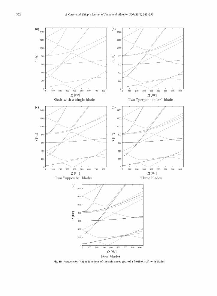
Fig. 10. Frequencies (Hz) as functions of the spin speed (Hz) of a flexible shaft with blades.
E. Carrera, M. Filippi / Journal of Sound and Vibration 366 (2016) 343–356352
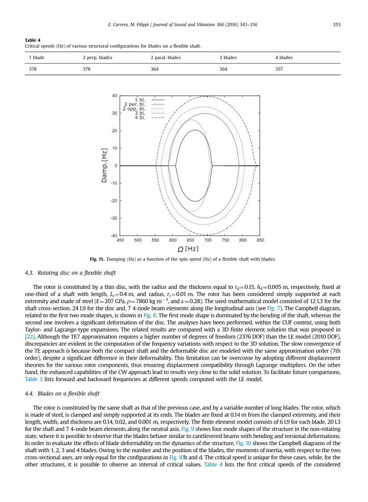
Table 4Critical speeds (Hz) of various structural configurations for blades on a flexible shaft.
1 blade 2 perp. blades 2 paral. blades 3 blades 4 blades
378 378 364 364 357
Fig. 11. Damping (Hz) as a function of the spin speed (Hz) of a flexible shaft with blades.
E. Carrera, M. Filippi / Journal of Sound and Vibration 366 (2016) 343–356 353
4.3. Rotating disc on a flexible shaft
The rotor is constituted by a thin disc, with the radius and the thickness equal to rd¼0.15, hd¼0.005 m, respectively, fixed atone-third of a shaft with length, Ls¼0.4 m, and radius, rs¼0.01 m. The rotor has been considered simply supported at eachextremity and made of steel (E¼207 GPa, ρ¼7860 kgm�3, and ν¼0.28). The used mathematical model consisted of 12 L3 for theshaft cross-section, 24 L9 for the disc and, 7 4-node beam elements along the longitudinal axis (see Fig. 7). The Campbell diagram,related to the first twomode shapes, is shown in Fig. 8. The first mode shape is dominated by the bending of the shaft, whereas thesecond one involves a significant deformation of the disc. The analyses have been performed, within the CUF context, using bothTaylor- and Lagrange-type expansions. The related results are compared with a 3D finite element solution that was proposed in[22]. Although the TE7 approximation requires a higher number of degrees of freedom (2376 DOF) than the LE model (2010 DOF),discrepancies are evident in the computation of the frequency variations with respect to the 3D solution. The slow convergence ofthe TE approach is because both the compact shaft and the deformable disc are modeled with the same approximation order (7thorder), despite a significant difference in their deformability. This limitation can be overcome by adopting different displacementtheories for the various rotor components, thus ensuring displacement compatibility through Lagrange multipliers. On the otherhand, the enhanced capabilities of the CW approach lead to results very close to the solid solution. To facilitate future comparisons,Table 3 lists forward and backward frequencies at different speeds computed with the LE model.
4.4. Blades on a flexible shaft
The rotor is constituted by the same shaft as that of the previous case, and by a variable number of long blades. The rotor, whichis made of steel, is clamped and simply supported at its ends. The blades are fixed at 0.14m from the clamped extremity, and theirlength, width, and thickness are 0.14, 0.02, and 0.001 m, respectively. The finite element model consists of 6 L9 for each blade, 20 L3for the shaft and 7 4-node beam elements along the neutral axis. Fig. 9 shows four mode shapes of the structure in the non-rotatingstate, where it is possible to observe that the blades behave similar to cantilevered beams with bending and torsional deformations.In order to evaluate the effects of blade deformability on the dynamics of the structure, Fig. 10 shows the Campbell diagrams of theshaft with 1, 2, 3 and 4 blades. Owing to the number and the position of the blades, the moments of inertia, with respect to the twocross-sectional axes, are only equal for the configurations in Fig. 10b and d. The critical speed is unique for these cases, while, for theother structures, it is possible to observe an interval of critical values. Table 4 lists the first critical speeds of the considered
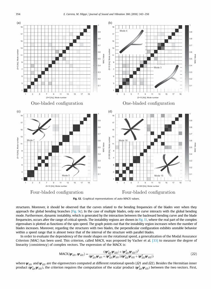
Fig. 12. Graphical representations of auto-MACX values.
E. Carrera, M. Filippi / Journal of Sound and Vibration 366 (2016) 343–356354
structures. Moreover, it should be observed that the curves related to the bending frequencies of the blades veer when theyapproach the global bending branches (Fig. 9c). In the case of multiple blades, only one curve interacts with the global bendingmode. Furthermore, dynamic instability, which is generated by the interaction between the backward bending curve and the bladefrequencies, occurs after the range of critical speeds. The instability regions are shown in Fig. 11, where the real part of the complexeigenvalues is plotted as functions of the spin speed. The graph points out that the instability region increases when the number ofblades increases. Moreover, regarding the structures with two blades, the perpendicular configuration exhibits unstable behaviorwithin a speed range that is almost twice that of the interval of the structure with parallel blades.
In order to evaluate the dependency of the mode shapes on the rotational speed, a generalization of the Modal AssuranceCriterion (MAC) has been used. This criterion, called MACX, was proposed by Vacher et al. [33] to measure the degree oflinearity (consistency) of complex vectors. The expression of the MACX is:
MACX ψΩ1;ψΩ2
� �¼ ðjψ�Ω1ψΩ2jþjψT
Ω1ψΩ2jÞ2ðψ�
Ω1ψΩ1þjψTΩ1ψΩ1jÞðψ�
Ω2ψΩ2þjψTΩ2ψΩ2jÞ
(22)
where ψΩ1 and ψΩ2 are the eigenvectors computed at different rotational speeds (Ω1 andΩ2). Besides the Hermitian innerproduct ðψ�
Ω1ψΩ2Þ, the criterion requires the computation of the scalar product ðψTΩ1ψΩ2Þ between the two vectors. First,
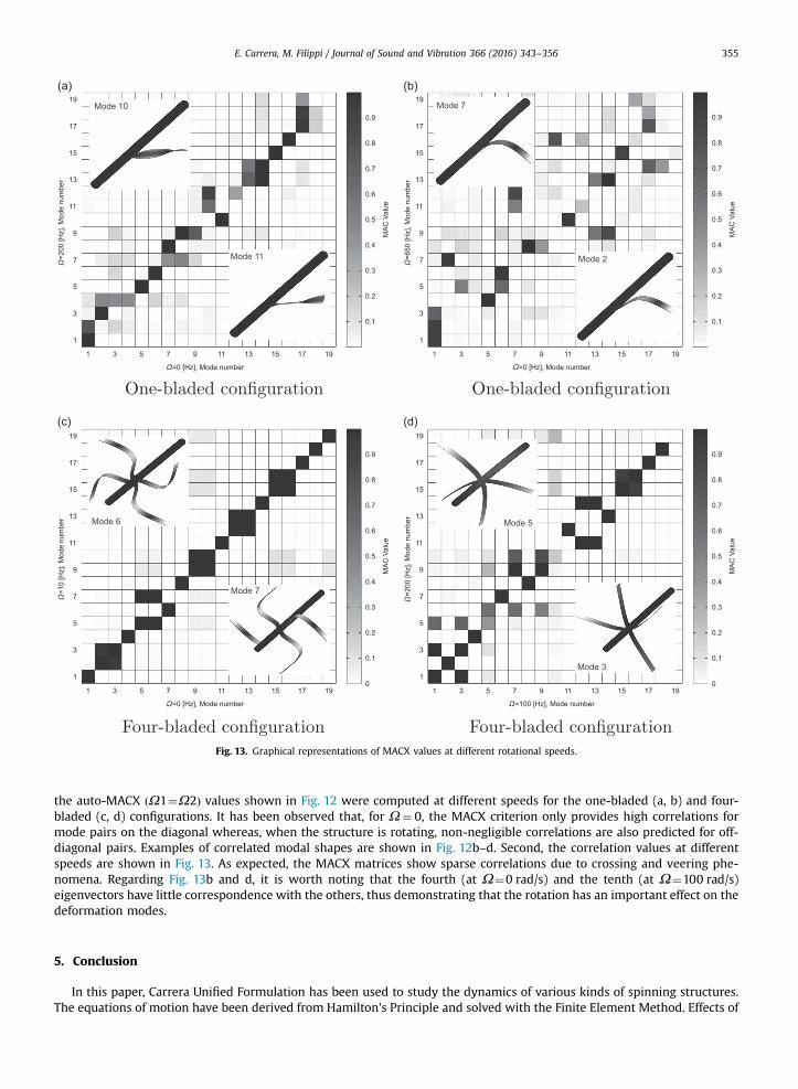
Fig. 13. Graphical representations of MACX values at different rotational speeds.
E. Carrera, M. Filippi / Journal of Sound and Vibration 366 (2016) 343–356 355
the auto-MACX ðΩ1¼Ω2Þ values shown in Fig. 12 were computed at different speeds for the one-bladed (a, b) and four-bladed (c, d) configurations. It has been observed that, for Ω¼ 0, the MACX criterion only provides high correlations formode pairs on the diagonal whereas, when the structure is rotating, non-negligible correlations are also predicted for off-diagonal pairs. Examples of correlated modal shapes are shown in Fig. 12b–d. Second, the correlation values at differentspeeds are shown in Fig. 13. As expected, the MACX matrices show sparse correlations due to crossing and veering phe-nomena. Regarding Fig. 13b and d, it is worth noting that the fourth (at Ω¼0 rad/s) and the tenth (at Ω¼100 rad/s)eigenvectors have little correspondence with the others, thus demonstrating that the rotation has an important effect on thedeformation modes.
5. Conclusion
In this paper, Carrera Unified Formulation has been used to study the dynamics of various kinds of spinning structures.The equations of motion have been derived from Hamilton's Principle and solved with the Finite Element Method. Effects of
E. Carrera, M. Filippi / Journal of Sound and Vibration 366 (2016) 343–356356
the initial stress have been included in the present one-dimensional formulation. Analyses have been performed on thindiscs, rings and bladed-shafts made of metallic material. The main results show the following:
� the proposed beam elements enable the natural frequencies of deformable structures to be predicted with a high-level ofaccuracy;
� unlike classical beam theories, the 1D-CUF models enable the initial stress and the related geometrical stiffness matrix tobe included;
� unlike the TE approach, the LE elements enable different structural components to be modeled with arbitrary orders ofaccuracy;
� the LE elements enable non-conventional boundary conditions (for example the disc clamped at the bore) to be modeled;� the LE approach enables the stability of non-axisymmetric configurations to be evaluated.
References
[1] H.F. Bauer, Vibration of a rotating uniform beam, Part 1: Orientation in the axis of rotation, Journal of Sound and Vibration 72 (1980) 177–189.[2] G. Curti, F.A. Raffa, F. Vatta, The dynamic stiffness matrix method in the analysis of rotating systems, Tribology Transactions 34 (1991) 81–85.[3] G. Curti, F.A. Raffa, F. Vatta, An anaytical approach to the dynamics of rotating shafts, Meccanica 27 (1992) 285–292.[4] O.A. Bauchau, Optimal design of high speed rotating graphite/epoxy shafts, Journal of Composite Materials 17 (1983) 170–180.[5] L.W. Chen, W.K. Peng, The stability behavior of rotating composite shafts under axial compressive loads, Composite Structures 41 (1998) 253–263.[6] C.W. Bert, C.D. Kim, Whirling of composite-material driveshafts including bending-twisting coupling and transverse shear deformation, Journal of
Vibration and Acoustics 17 (1995) 17–21.[7] O. Song, L. Librescu, Anisotropy and structural coupling on vibration and instability of spinning thin-walled beams, Journal of Sound and Vibration 204
(1997) 477–494.[8] O. Song, L. Librescu, N.-H. Jeong, Vibration and stability of prestwisted spinning thin-walled composite beams featuring bending-bending elastic
coupling, Journal of Sound and Vibration 237 (2000) 513–533.[9] T. Saito, M. Endo, Vibration of finite length rotating cylindrical shells, Journal of Sound and Vibration 107 (1985) 17–28.
[10] Y. Chen, H.B. Zhao, Z.P. Shen, I. Grieger, B.-H. Kröplin, Vibrations of high speed rotating shells with calculations for cylindrical shells, Journal of Soundand Vibration 160 (1993) 137–160.
[11] D. Guo, Z. Zheng, F. Chu, Vibration analysis of spinning cylindrical shells by finite element method, International Journal of Solids and Structures 39(2002) 725–739.
[12] D. Guo, F.L. Chu, Z.C. Zheng, The influence of rotation on vibration of a thick cylindrical shell, Journal of Sound and Vibration 242 (2001) 487–505.[13] Shupeng Sun, Shiming Chu, Dengqing Cao, Vibration characteristics of thin rotating cylindrical shells with various boundary conditions, Journal of
Sound and Vibration 331 (2012) 4170–4186.[14] K.Y. Lam, C.T. Loy, Analysis of rotating laminated cylindrical shells by different thin shell theories, Journal of Sound and Vibration 186 (1995) 23–35.[15] K.Y. Lam, C.T. Loy, Influence of boundary conditions for a thin laminated rotating cylindrical shell, Composite Structures 41 (1998) 215–228.[16] Y.S. Lee, Y.W. Kim, Vibration analysis of rotating composite cylindrical shells with orthogonal stiffeners, Computers and Structures 69 (1998) 271–281.[18] E. Chatelet, D. Lornage, G. Jacquet-Richardet, A three dimensional modeling of the dynamic behavior of composite rotors, International Journal of
Rotating Machinery 8 (2002) 185–192.[19] G.H. Jang, S.H. Lee, Free vibration analysis of a spinning flexible disk-spindle system supported by ball bearing and flexible shaft using the finite
element method and substructure synthesis, Journal of Sound and Vibration 251 (2002) 59–78.[20] G.H. Jang, J.H. Han, Finite element modal analysis of a spinning flexible disk-spindle systemin a hdd considering the flexibility of complicated sup-
porting structure, Microsystem Technologies 11 (2005) 766–778, http://dx.doi.org/10.1007/s00542-005-0579-4.[21] G. Genta, Chen Feng, A. Tonoli, Dynamics behavior of rotating bladed discs: a finite element formulation for the study of second and higher order
harmonics, Journal of Sound and Vibration 329 (2010) 5289–5306.[22] D. Combescure, A. Lazarus, Refined finite element modelling for the vibration analysis of large rotating machines: application to the gas turbine
modular helium reactor power conversion unit, Journal of Sound and Vibration 318 (2008) 1262–1280, http://dx.doi.org/10.1016/j.jsv.2008.04.025.[23] G. Genta, Dynamics of Rotating Systems, Springer, New York, 2005.[24] V. Ganine, D. Laxalde, H. Michalska, C. Pierre, Parameterized reduced order modeling of misaligned stacked disks rotor assemblies, Journal of Sound
and Vibration 330 (2010) 445–460, http://dx.doi.org/10.1016/j.jsv.2010.08.026.[25] M.B. Wagner, A. Younan, P. Allaire, R. Cogill, Model reduction methods for rotor dynamic analysis: a survey and review, International Journal of Rotating
Machinery (2010) 1–17, http://dx.doi.org/10.1155/2010/273716.[26] E. Carrera, G. Giunta, M. Petrolo, Beam Structures—Classical and Advanced Theories, Wiley, Chichester, West Sussex, United Kingdom, 2011.[27] E. Carrera, M. Filippi, E. Zappino, Analysis of rotor dynamic by one-dimensional variable kinematic theories, Journal of Engineering for Gas Turbines and
Power 135 (2013) 092501–092510, http://dx.doi.org/10.1115/1.4024381.[28] E. Carrera, M. Filippi, Variable kinematic one-dimensional finite elements for the analysis of rotors made of composite materials, Journal of Engineering
for Gas Turbines and Power 136 (2014) 092501–092512, http://dx.doi.org/10.1115/1.4027192.[29] E. Carrera, M. Filippi, Vibration analysis of thin/thick, composites/metallic spinning cylindrical shells by refined beam models, Journal of Vibration and
Acoustics 137 (2015) 031020–031029, http://dx.doi.org/10.1115/1.4029688.[30] E. Carrera, M. Petrolo, Refined beam elements with only displacement variables and plate/shell capabilities, Meccanica 47 (2012) 537–556.[31] E. Carrera, M. Petrolo, Refined one-dimensional formulations for laminated structure analysis, AIAA Journal 50 (2012) 176–189.[33] P. Vacher, B. Jacquier, A. Bucharles, Extensions of the mac criterion to complex modes, Proceedings of ISMA2010 including USD2010, Leuven, November
2010, pp. 2713–2726.[34] G.J. Wilson, J. Kirkhope, Vibration analysis of axial flow turbine disks using finite elements, Journal of Engineering for Industry 98 (1976) 1008–1013,
http://dx.doi.org/10.1115/1.3438992.