Embed Size (px)
DESCRIPTION
interfacing
Citation preview
The Parallel Printer Port
The PC parallel printer port is an interface between the computer and the printer. It is called parallel because the data is sent in parallel or by group of bits at a time unlike serial flow wherein data is sent one bit at a time.
While the parallel port is designed specifically for the printer, it can also be used as an interface to other electronic/electrical devices.
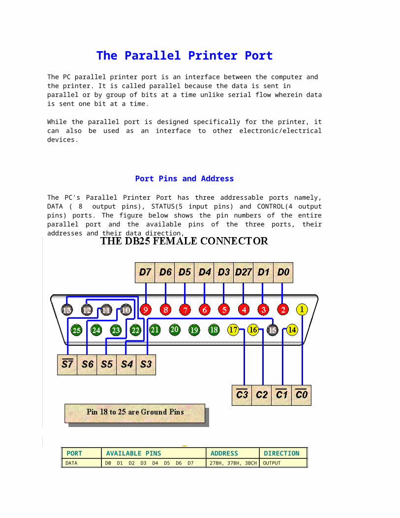
Port Pins and Address
The PC's Parallel Printer Port has three addressable ports namely, DATA ( 8 output pins), STATUS(5 input pins) and CONTROL(4 output pins) ports. The figure below shows the pin numbers of the entire parallel port and the available pins of the three ports, their addresses and their data direction,
PORT AVAILABLE PINS ADDRESS DIRECTION DATA D0 D1 D2 D3 D4 D5 D6 D7 278H, 378H, 3BCH OUTPUT
STATUS - - - S3 S4 S5 S6 S7 279H, 379H, 3BDH INPUT
CONTROL C0 C1 C2 C3 - - - - 27AH, 37AH, 3BEH OUTPUT
S7 pin of the status port is active low. Since this is an input pin, the bit that will enter here will be inverted when the computer reads this. C0 C1 and C3 are also active low pins. This means
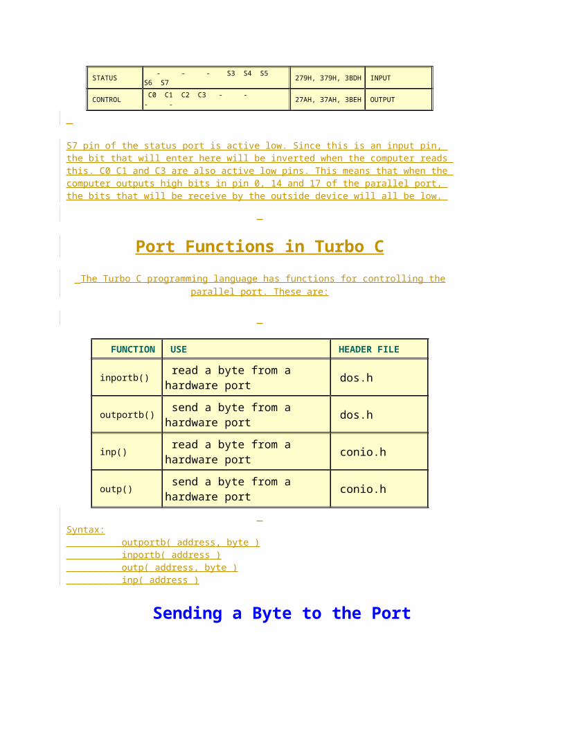
that when the computer outputs high bits in pin 0, 14 and 17 of the parallel port, the bits that will be receive by the outside device will all be low.
Port Functions in Turbo C
The Turbo C programming language has functions for controlling the parallel port. These are:
FUNCTION USE HEADER FILE
inportb() read a byte from a hardware port dos.h
outportb() send a byte from a hardware port dos.h
inp() read a byte from a hardware port conio.h
outp() send a byte from a hardware port conio.h
Syntax: outportb( address, byte ) inportb( address ) outp( address, byte ) inp( address )
Sending a Byte to the Port
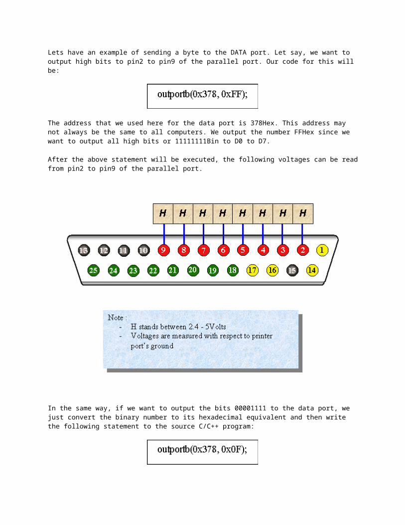
Lets have an example of sending a byte to the DATA port. Let say, we want to output high bits to pin2 to pin9 of the parallel port. Our code for this will be:
The address that we used here for the data port is 378Hex. This address may not always be the same to all computers. We output the number FFHex since we want to output all high bits or 11111111Bin to D0 to D7.
After the above statement will be executed, the following voltages can be read from pin2 to pin9 of the parallel port.
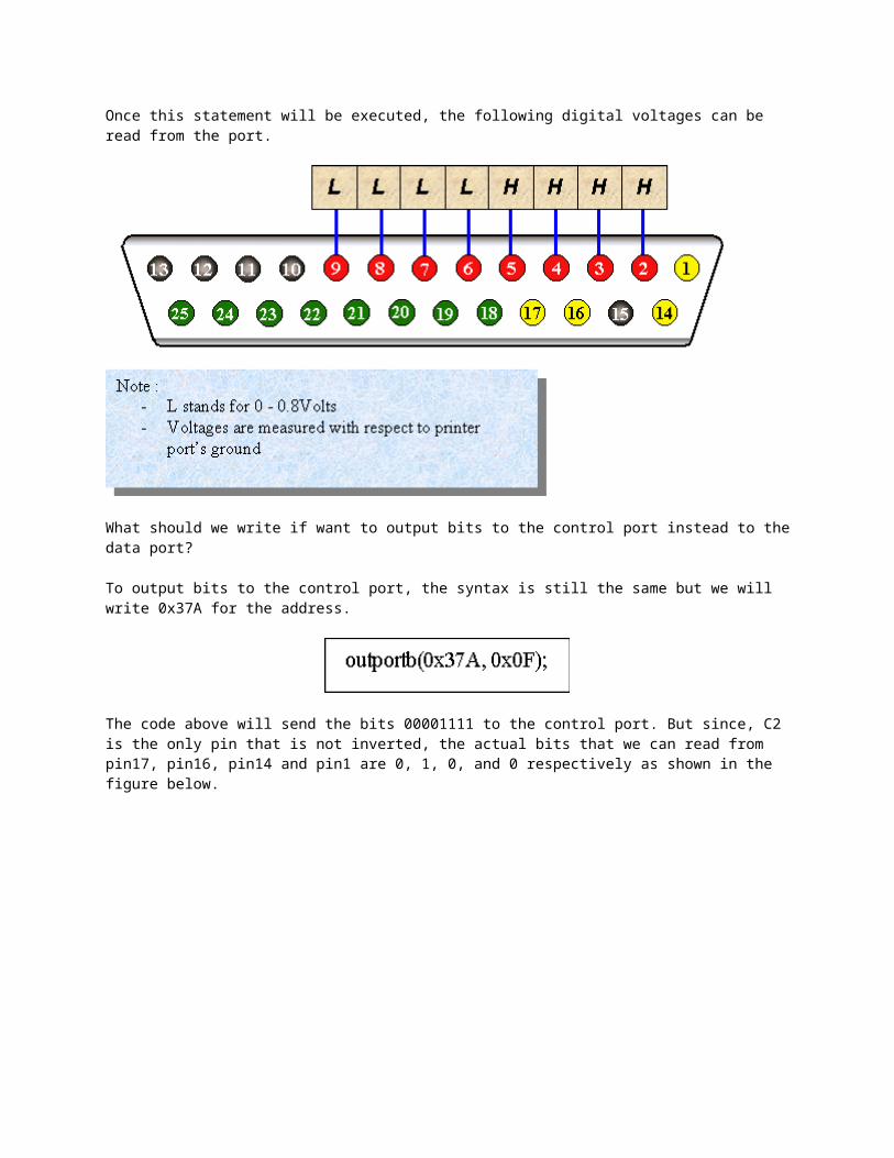
In the same way, if we want to output the bits 00001111 to the data port, we just convert the binary number to its hexadecimal equivalent and then write the following statement to the source C/C++ program:
Once this statement will be executed, the following digital voltages can be read from the port.
What should we write if want to output bits to the control port instead to the data port?
To output bits to the control port, the syntax is still the same but we will write 0x37A for the address.
The code above will send the bits 00001111 to the control port. But since, C2 is the only pin that is not inverted, the actual bits that we can read from pin17, pin16, pin14 and pin1 are 0, 1, 0, and 0 respectively as shown in the figure below.
The number that we write in our code is not actually the number that can be read from the port. So, if we really want to have 1111 bits to the control port, we should output the bits 0100. Our code will now look like this :
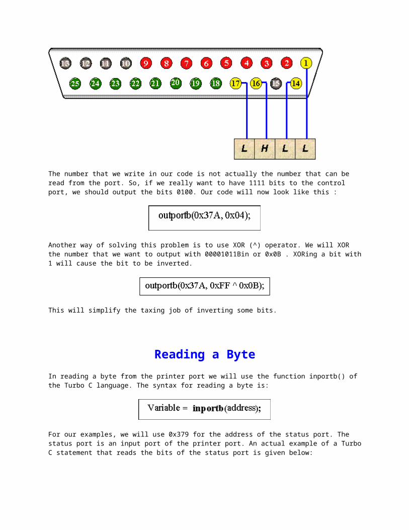
Another way of solving this problem is to use XOR (^) operator. We will XOR the number that we want to output with 00001011Bin or 0x0B . XORing a bit with 1 will cause the bit to be inverted.
This will simplify the taxing job of inverting some bits.
Reading a Byte
In reading a byte from the printer port we will use the function inportb() of the Turbo C language. The syntax for reading a byte is:
For our examples, we will use 0x379 for the address of the status port. The status port is an input port of the printer port. An actual example of a Turbo C statement that reads the bits of the status port is given below:
We use input as our variable. Executing this statement will cause the bits in the status port to be read and store it to variable input.
If for example, the pins of the status port is connected to a +5 volts supply as illustrated below.
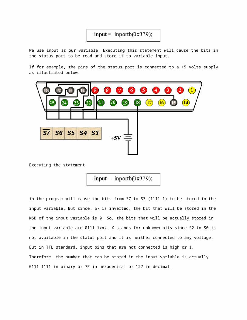
Executing the statement,
in the program will cause the bits from S7 to S3 (1111 1) to be stored in the input variable. But since, S7
is inverted, the bit that will be stored in the MSB of the input variable is 0. So, the bits that will be actually
stored in the input variable are 0111 1xxx. X stands for unknown bits since S2 to S0 is not available in the
status port and it is neither connected to any voltage. But in TTL standard, input pins that are not
connected is high or 1. Therefore, the number that can be stored in the input variable is actually 0111
1111 in binary or 7F in hexadecimal or 127 in decimal.
Interfacing with LED
To interface an LED, the cathode should be connected towards the port of the computer and anode towards the positive five volts external supply.
A series resistor, typically 330 ohms, must be present to limit the current passing through the LED.
or
The ground of the external power supply must also be connected to the ground of the parallel port.
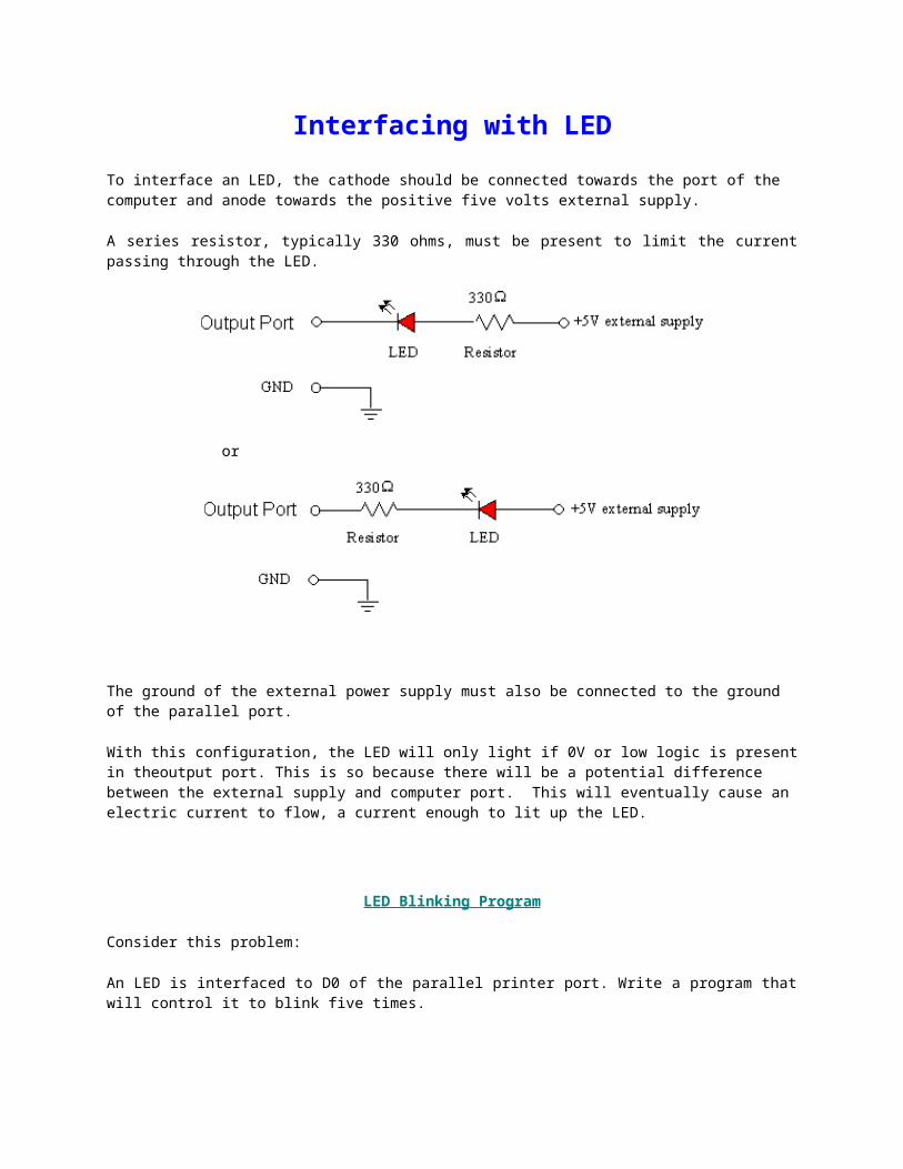
With this configuration, the LED will only light if 0V or low logic is present in theoutput port. This is so because there will be a potential difference between the external supply and computer port. This will eventually cause an electric current to flow, a current enough to lit up the LED.
LED Blinking Program
Consider this problem:
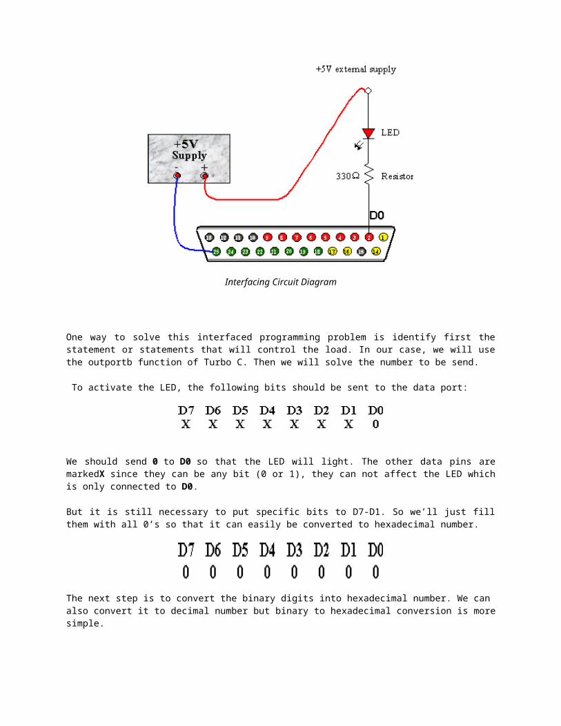
An LED is interfaced to D0 of the parallel printer port. Write a program that will control it to blink five times.
Interfacing Circuit Diagram
One way to solve this interfaced programming problem is identify first the statement or statements that will control the load. In our case, we will use the outportb function of Turbo C. Then we will solve the number to be send.
To activate the LED, the following bits should be sent to the data port:
We should send 0 to D0 so that the LED will light. The other data pins are markedX since they can be any bit (0 or 1), they can not affect the LED which is only connected to D0.
But it is still necessary to put specific bits to D7-D1. So we’ll just fill them with all 0’s so that it can easily be converted to hexadecimal number.
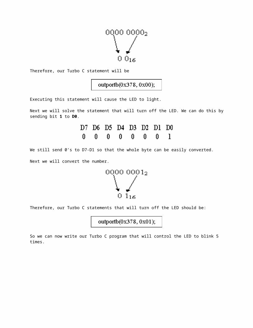
The next step is to convert the binary digits into hexadecimal number. We can also convert it to decimal number but binary to hexadecimal conversion is more simple.
Therefore, our Turbo C statement will be
Executing this statement will cause the LED to light.
Next we will solve the statement that will turn off the LED. We can do this by sending bit 1 to D0.
We still send 0’s to D7-D1 so that the whole byte can be easily converted.
Next we will convert the number.
Therefore, our Turbo C statements that will turn off the LED should be:
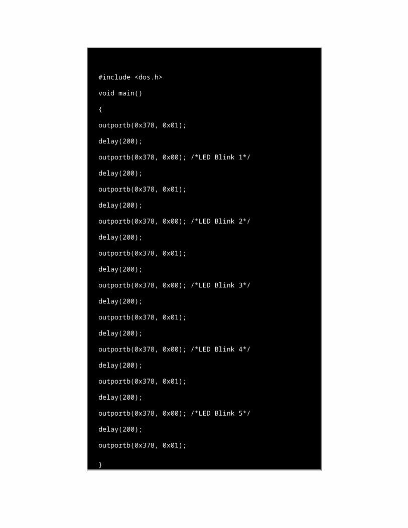
So we can now write our Turbo C program that will control the LED to blink 5 times.
#include <dos.h>
void main()
{
outportb(0x378, 0x01);
delay(200);
outportb(0x378, 0x00); /*LED Blink 1*/
delay(200);
outportb(0x378, 0x01);
delay(200);
outportb(0x378, 0x00); /*LED Blink 2*/
delay(200);
outportb(0x378, 0x01);
delay(200);
outportb(0x378, 0x00); /*LED Blink 3*/
delay(200);
outportb(0x378, 0x01);
delay(200);
outportb(0x378, 0x00); /*LED Blink 4*/
delay(200);
outportb(0x378, 0x01);
delay(200);
outportb(0x378, 0x00); /*LED Blink 5*/
delay(200);
outportb(0x378, 0x01);
}
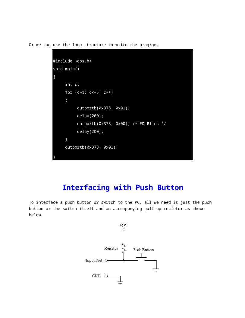
Or we can use the loop structure to write the program.
#include <dos.h>
void main()
{
int c;
for (c=1; c<=5; c++)
{
outportb(0x378, 0x01);
delay(200);
outportb(0x378, 0x00); /*LED Blink */
delay(200);
}
outportb(0x378, 0x01);
}
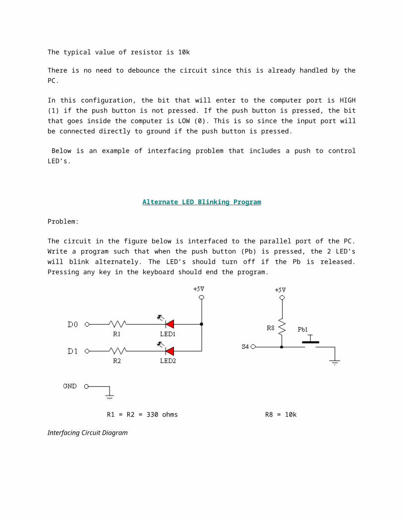
Interfacing with Push Button
To interface a push button or switch to the PC, all we need is just the push button or the switch itself and an accompanying pull-up resistor as shown below.
The typical value of resistor is 10k
There is no need to debounce the circuit since this is already handled by the PC.
In this configuration, the bit that will enter to the computer port is HIGH (1) if the push button is not pressed. If the push button is pressed, the bit that goes inside the computer is LOW (0). This is so since the input port will be connected directly to ground if the push button is pressed.
Below is an example of interfacing problem that includes a push to control LED’s.
Alternate LED Blinking Program
Problem:
The circuit in the figure below is interfaced to the parallel port of the PC. Write a program such that when the push button (Pb) is pressed, the 2 LED’s will blink alternately. The LED’s should turn off if the Pb is released. Pressing any key in the keyboard should end the program.
R1 = R2 = 330 ohms R8 = 10k
Interfacing Circuit Diagram
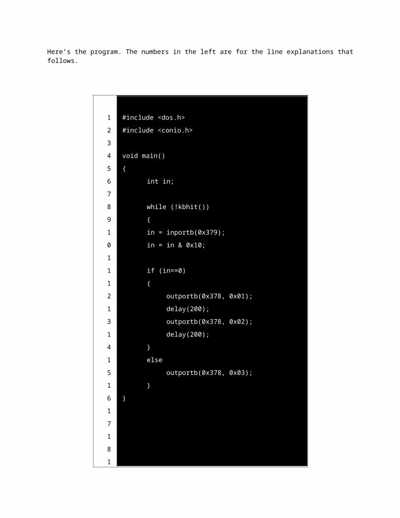
Here’s the program. The numbers in the left are for the line explanations that follows.
1
2
#include <dos.h>
#include <conio.h>
3
4
5
6
7
8
9
1
0
1
1
1
2
1
3
1
4
1
5
1
6
1
7
1
8
1
9
2
0
2
1
2
2
void main()
{
int in;
while (!kbhit())
{
in = inportb(0x379);
in = in & 0x10;
if (in==0)
{
outportb(0x378, 0x01);
delay(200);
outportb(0x378, 0x02);
delay(200);
}
else
outportb(0x378, 0x03);
}
}
2
3
Line explanations
1. header file for inportb, outportb and delay functions
2. header file for kbhit function
3. line space to make the program more readable
4. main function
5. open brace for main function
6. variable declaration of integer in
7. line space to make the program more readable
8. while loop with true condition if no key is pressed in the keyboard
9. open brace for while
10. read the status port and assigned the value to variable in
11. in variable masked with 0001 00002 so that variable in will only have two possible values, 0000 00002 (016)if the push button is pressed and 0001 00002 (1016)if the push button is not pressed
12.space to make the program more readable
13. if statement which will be true if value of in is 0(meaning, the push button is pressed)
14.open brace of if
15.output the bits 0000 00012 to the data port which will cause LED2 to light and LED1 no light
16.delay function to be able to observe the lighting of the LED
17. output the bits 0000 00102 to the data port which will cause LED1 to light and LED2 no light
18.delay function to be able to observe the lighting of the LED
19.close brace of if statement
20.else statement that will be executed if the push button is not pressed
21.output the bits 0000 00112 to the data port which will cause LED1 and LED2 to turn off
22.close brace of while loop
23.close brace of main function, the end of program.
Interfacing with 7-Segment Display
A 7-segment display is compose of seven LED’s. So interfacing it to the computer port is just similar as with interfacing with LED. There are two kinds of 7-segment display, common-anode and common-cathode. In common-anode 7-segment display, the anodes of the seven LED's are internally connected while In common-cathode 7-segment display, the cathodes anodes of the seven LED's are internally connected. The examples here focus only on common-anode 7-segment display.
There are two basic ways to interface 7-segment display to the computer, direct and indirect.
Direct Control of Seven-Segment Display
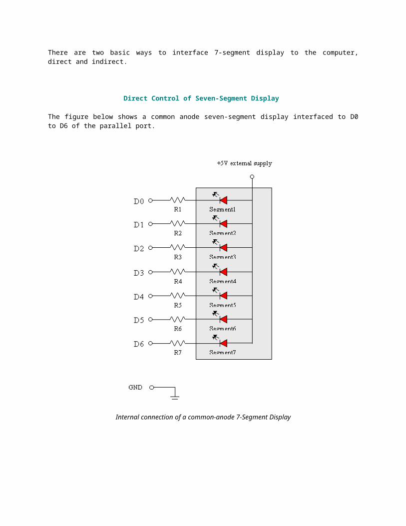
The figure below shows a common anode seven-segment display interfaced to D0 to D6 of the parallel port.
Internal connection of a common-anode 7-Segment Display
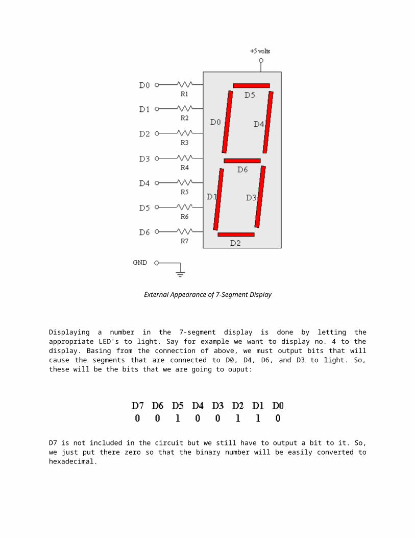
External Appearance of 7-Segment Display
Displaying a number in the 7-segment display is done by letting the appropriate LED's to light. Say for example we want to display no. 4 to the display. Basing from the connection of above, we must output bits that will cause the segments that are connected to D0, D4, D6, and D3 to light. So, these will be the bits that we are going to ouput:
D7 is not included in the circuit but we still have to output a bit to it. So, we just put there zero so that the binary number will be easily converted to hexadecimal.
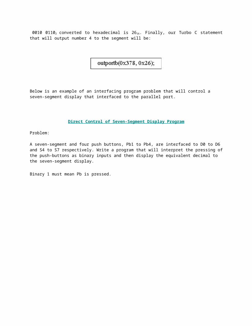
0010 01102 converted to hexadecimal is 2616. Finally, our Turbo C statement that will output number 4 to the segment will be:
Below is an example of an interfacing program problem that will control a seven-segment display that interfaced to the parallel port.
Direct Control of Seven-Segment Display Program
Problem:
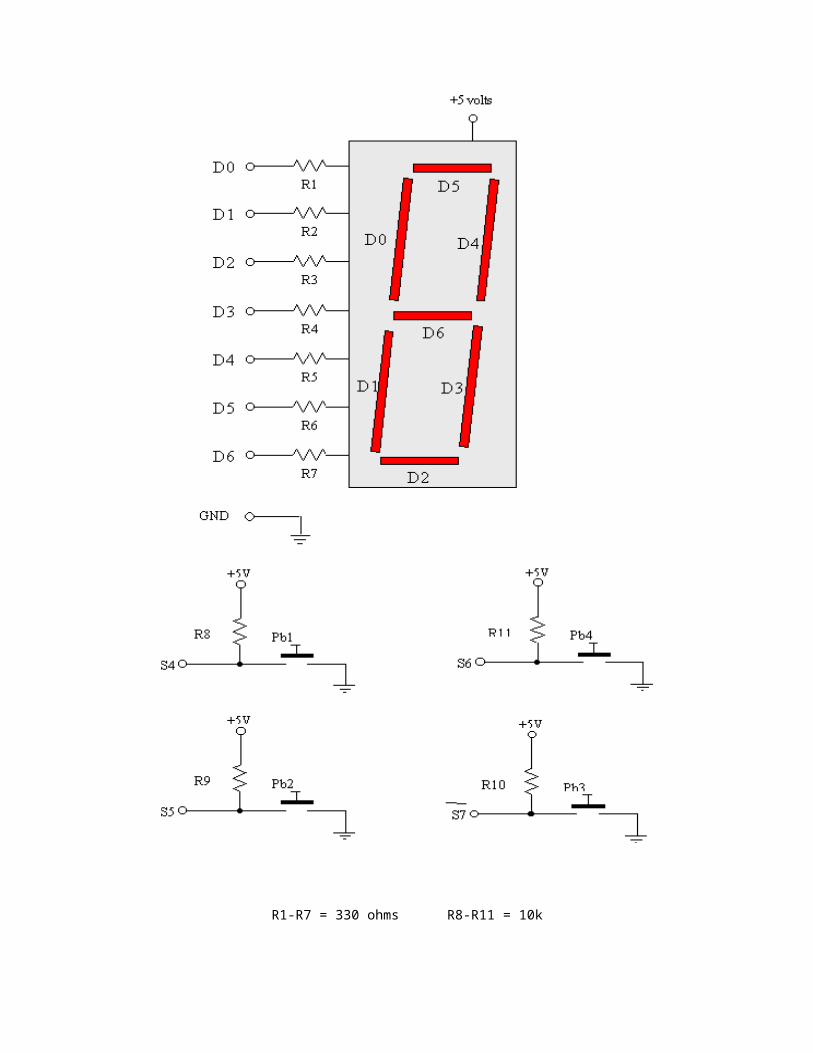
A seven-segment and four push buttons, Pb1 to Pb4, are interfaced to D0 to D6 and S4 to S7 respectively. Write a program that will interpret the pressing of the push-buttons as binary inputs and then display the equivalent decimal to the seven-segment display.
Binary 1 must mean Pb is pressed.
R1-R7 = 330 ohms R8-R11 = 10k
Interfacing Circuit Diagram
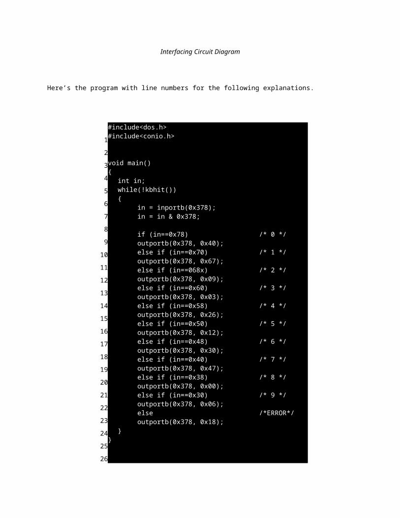
Here’s the program with line numbers for the following explanations.
a
1
2
3
4
5
6
7
8
9
10
11
12
13
14
15
16
17
18
19
20
21
22
23
24
25
26
27
28
#include<dos.h>#include<conio.h> void main(){
int in;while(!kbhit()) {
in = inportb(0x378);in = in & 0x378; if (in==0x78) /* 0 */outportb(0x378, 0x40);else if (in==0x70) /* 1 */outportb(0x378, 0x67);else if (in==068x) /* 2 */outportb(0x378, 0x09);else if (in==0x60) /* 3 */outportb(0x378, 0x03);else if (in==0x58) /* 4 */outportb(0x378, 0x26);else if (in==0x50) /* 5 */outportb(0x378, 0x12);else if (in==0x48) /* 6 */outportb(0x378, 0x30);else if (in==0x40) /* 7 */outportb(0x378, 0x47);else if (in==0x38) /* 8 */outportb(0x378, 0x00);else if (in==0x30) /* 9 */outportb(0x378, 0x06);else /*ERROR*/outportb(0x378, 0x18);
}}
29
30
31
32
33
34
35
36
Line Explanations
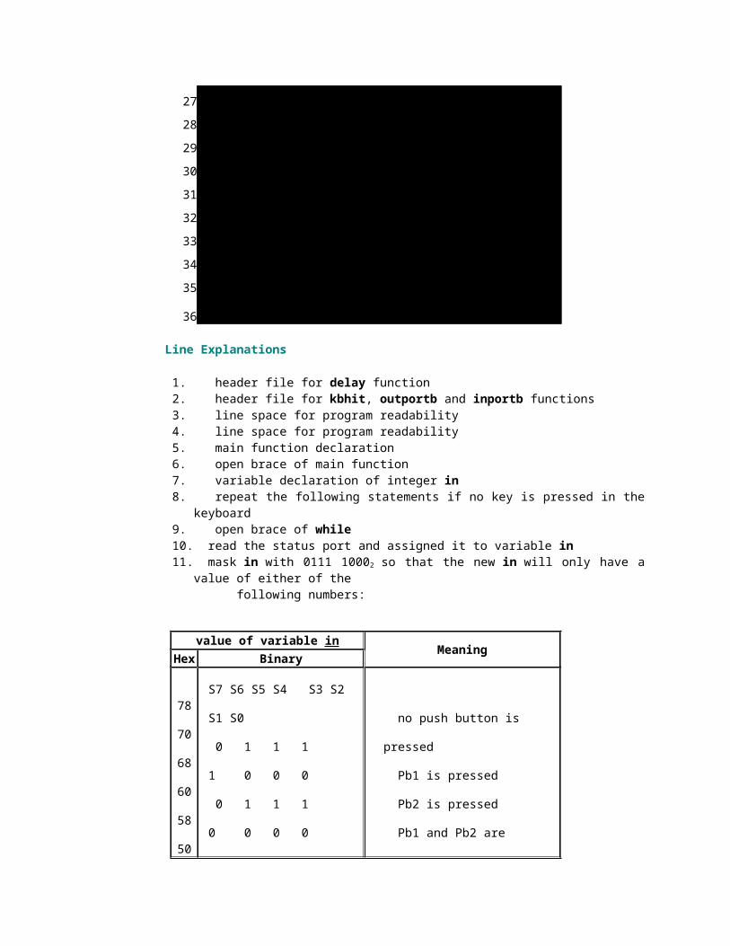
1. header file for delay function2. header file for kbhit, outportb and inportb functions3. line space for program readability4. line space for program readability5. main function declaration6. open brace of main function7. variable declaration of integer in8. repeat the following statements if no key is pressed in the keyboard9. open brace of while10. read the status port and assigned it to variable in11. mask in with 0111 10002 so that the new in will only have a value of either of the following numbers:
value of variable inMeaning
Hex Binaryw
78
70
68
60
58
50
48
40
38
30
S7 S6 S5 S4 S3 S2 S1 S0
0 1 1 1 1 0 0 0
0 1 1 1 0 0 0 0
0 1 1 0 1 0 0 0
0 1 1 0 0 0 0 0
0 1 0 1 1 0 0 0
0 1 0 1 0 0 0 0
0 1 0 0 1 0 0 0
0 1 0 0 0 0 0 0
0 0 1 1 1 0 0 0
no push button is pressed
Pb1 is pressed
Pb2 is pressed
Pb1 and Pb2 are pressed
Pb3 is pressed
Pb3 and Pb1are pressed
Pb3 and Pb2 are pressed
Pb3, Pb2, and Pb1 are pressed
Pb4 is pressed
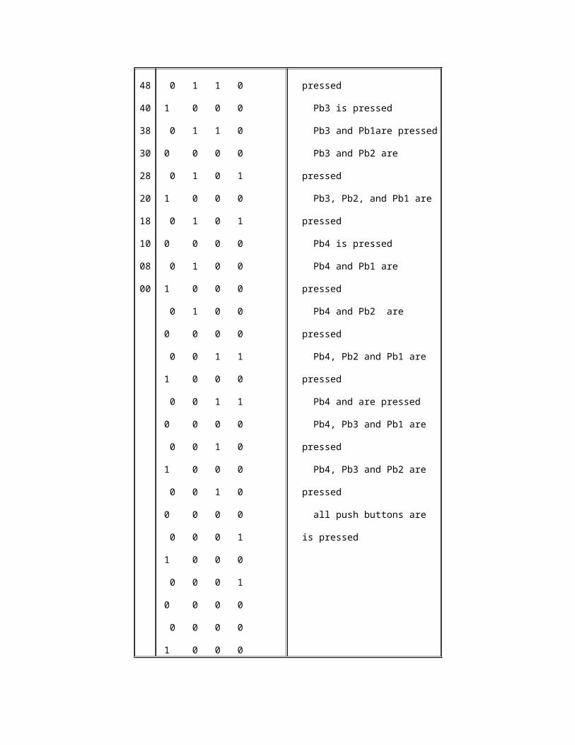
28
20
18
10
08
00
0 0 1 1 0 0 0 0
0 0 1 0 1 0 0 0
0 0 1 0 0 0 0 0
0 0 0 1 1 0 0 0
0 0 0 1 0 0 0 0
0 0 0 0 1 0 0 0
0 0 0 0 0 0 0 0
Pb4 and Pb1 are pressed
Pb4 and Pb2 are pressed
Pb4, Pb2 and Pb1 are pressed
Pb4 and are pressed
Pb4, Pb3 and Pb1 are pressed
Pb4, Pb3 and Pb2 are pressed
all push buttons are is pressed
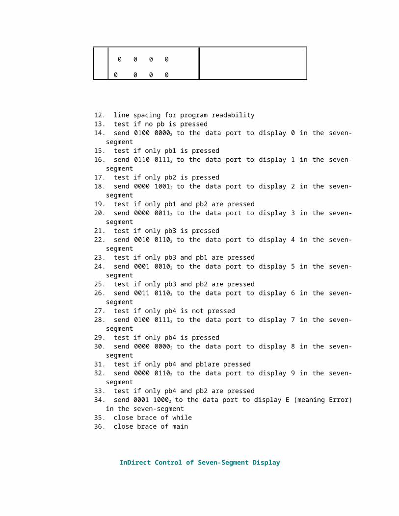
12. line spacing for program readability13. test if no pb is pressed14. send 0100 00002 to the data port to display 0 in the seven-segment15. test if only pb1 is pressed16. send 0110 01112 to the data port to display 1 in the seven-segment17. test if only pb2 is pressed18. send 0000 10012 to the data port to display 2 in the seven-segment19. test if only pb1 and pb2 are pressed20. send 0000 00112 to the data port to display 3 in the seven-segment 21. test if only pb3 is pressed22. send 0010 01102 to the data port to display 4 in the seven-segment23. test if only pb3 and pb1 are pressed24. send 0001 00102 to the data port to display 5 in the seven-segment25. test if only pb3 and pb2 are pressed26. send 0011 01102 to the data port to display 6 in the seven-segment27. test if only pb4 is not pressed28. send 0100 01112 to the data port to display 7 in the seven-segment29. test if only pb4 is pressed30. send 0000 00002 to the data port to display 8 in the seven-segment31. test if only pb4 and pb1are pressed32. send 0000 01102 to the data port to display 9 in the seven-segment33. test if only pb4 and pb2 are pressed34. send 0001 10002 to the data port to display E (meaning Error) in the seven-segment35. close brace of while36. close brace of main
InDirect Control of Seven-Segment Display
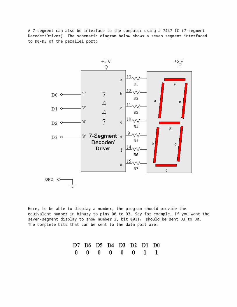
A 7-segment can also be interface to the computer using a 7447 IC (7-segment Decoder/Driver). The schematic diagram below shows a seven segment interfaced to D0-D3 of the parallel port:
Here, to be able to display a number, the program should provide the equivalent number in binary to pins D0 to D3. Say for example, If you want the seven-segment display to show number 3, bit 00112 should be sent D3 to D0. The complete bits that can be sent to the data port are:
D4 to D7 have no connections so it can be set to zero for ease of number conversion. Finally, the C/C++ statement that will cause the above seven-segment to display 3 is:
Below is a problem for indirect control of seven segment-display.
Indirect Control of Seven-Segment Display Program
Problem:
A 7-segment Display is interfaced to the computer through a 7447 IC. Write a program that will cause the display to show up-counting and down counting.
R1-R7 = 330 ohms
Interfacing Circuit Diagram
Here’s the program with line numbers for the following explanations.
123
#include <dos.h> void main()
45678910111213141516
{ int c; for(c=0; c<10; c++) { outportb(0x378, c); delay(1000); } for(c=9; c>=0; c--) { outportb(0x378, c); delay(1000); }}
Line Explanations
1. header file for delay, outportb and inportb functions2. line space for program readability3. main function declaration4. open brace of main function5. variable declaration of integer c6. loop for count-up7. open brace of for8. output the value of c to the data port9. time delay to be able to see the display10. close brace of for11. second loop for count-down12. open brace of for13. output the value of c to the data port14. time delay to be able to see the display15. close brace of for16. close brace of main