Embed Size (px)
Citation preview

Revision history Table of revisions
Date Changed Rev
November 2018 Moved PR2, PP2 grip cover option H8-Y and put in circle and lowered; Added note to top ofElectronic modules chapter; Updated JS1-H Analog Category 1 and 3 wiring connectiondiagrams; Changed FNR IP to IP 66; Under Mechanical, changed table Friction hold/Springreturn, base only, row 1 code to E and row 2 code to J; JS1-H Base model code Table C,added row PEP; Table D, Changed row 1 code to E and row 2 code to J that applies onlywhen using XF base; added sub-topic JS1 Heavy Duty Joystick critical mounting under topicJoystick safety critical functions
1101
August 2018 Updated for spring/friction base 1001
June 2018 Changed vertical maximum load; Added table under Joystick Functions for OperatorPresence Switch (PR7, PPR grip only); Added A and E options for Operator Presence Switch,in last two rows of table H8-Defining grip side, under chapter Product configuration modelcode.
0901
March 2018 Removed J options from PR7, PP7 grip faceplate options; Added Grip only sales and serviceoptions topic; removed the wire color column from all connectors pin tables; corrected H4through H12 tables under Grip model code; added to types of grips offered for applicationsthat require high ingress protection; and listed grips with Operator Presence Switch inProduct configuration model code table H7 and H8
0801
January 2018 Added Analog Cat 1, 3 information 0701
November 2017 Added CANalog and CAN+ information 0601
January 2017 Pushbutton color codes updated 0503
January 2017 Removed information that does not apply, corrected PR2 grip options information 0502
December 2016 Added PVE information 0501
October 2016 Updated PR2 faceplate designation; and Environmental IP rating 0403
September 2016 Updated Operating temperature for CAN to 85° C in Environmental table 0402
September 2016 Updates regarding IP switches; Common model code for J3-cable 0401
September 2016 Various updates; updated to Engineering Tomorrow design 0302
February 2016 Removed Connection diagrams chapter 0201
February 2016 First edition 0101
Technical InformationJS1 Heavy Duty Joysticks
2 | © Danfoss | November 2018 BC00000347en-001101

OverviewJS1-H description..............................................................................................................................................................................5Features................................................................................................................................................................................................5Options.................................................................................................................................................................................................6
HR1, HP1 gripDescription..........................................................................................................................................................................................7Dimensions......................................................................................................................................................................................... 8Ten total grip functions..................................................................................................................................................................8Function overview........................................................................................................................................................................... 9Faceplate options.............................................................................................................................................................................9Cover options.................................................................................................................................................................................. 10Base options.....................................................................................................................................................................................11
ST2, SP2 gripDimensions.......................................................................................................................................................................................13Five total grip functions...............................................................................................................................................................13Faceplate options.......................................................................................................................................................................... 14Cover options.................................................................................................................................................................................. 14
PR2, PP2 gripDimensions.......................................................................................................................................................................................16Twelve total grip functions.........................................................................................................................................................16Faceplate options.......................................................................................................................................................................... 17Cover options.................................................................................................................................................................................. 18
ST7, SP7 gripDimensions.......................................................................................................................................................................................20Faceplate options.......................................................................................................................................................................... 21Cover options.................................................................................................................................................................................. 22
PR7, PP7 gripDimensions.......................................................................................................................................................................................24Faceplate options.......................................................................................................................................................................... 25Cover options.................................................................................................................................................................................. 26
Compatible gripsGrip only sales and service options......................................................................................................................................... 27Dimensions.......................................................................................................................................................................................28
BaseDimensions.......................................................................................................................................................................................29
Electronic modulesCAN..................................................................................................................................................................................................... 30CAN+...................................................................................................................................................................................................30CANalog.............................................................................................................................................................................................30
Additional X and Y analog outputs.................................................................................................................................... 30Proportional roller output..................................................................................................................................................... 30
PVE.......................................................................................................................................................................................................30PVE—Standard................................................................................................................................................................................31PVE—Extended...............................................................................................................................................................................32Non-Redundant Analog interface (CAT1)............................................................................................................................. 32Full-Redundant Analog interface (CAT3)...............................................................................................................................32
Connection diagramsCAN+...................................................................................................................................................................................................33CANalog.............................................................................................................................................................................................34PVE DSUB.......................................................................................................................................................................................... 35Analog Cat 1.....................................................................................................................................................................................36Analog Cat 3.....................................................................................................................................................................................37PVE Deutsch..................................................................................................................................................................................... 38
Specifications
Technical InformationJS1 Heavy Duty Joysticks
Contents
© Danfoss | November 2018 BC00000347en-001101 | 3

Mechanical....................................................................................................................................................................................... 39Electrical—CAN, CAN+, and CANalog.................................................................................................................................... 40Electrical—PVE (Standard and Extended).............................................................................................................................40Electrical—PVE (Extended only)............................................................................................................................................... 40Electrical—Analog Cat 1, Cat 3..................................................................................................................................................41Environmental.................................................................................................................................................................................42
Joystick functionsGrip options..................................................................................................................................................................................... 43Push button......................................................................................................................................................................................43Roller...................................................................................................................................................................................................44FNR...................................................................................................................................................................................................... 45Toggle switch.................................................................................................................................................................................. 45Operator Presence switch...........................................................................................................................................................46
Connector options and cablingOne 6 pin connector..................................................................................................................................................................... 47Two 6 pin connectors................................................................................................................................................................... 48Two 12 pin connectors.................................................................................................................................................................49Two 12 pin and one 6 pin connectors.................................................................................................................................... 50One 18 pin connector...................................................................................................................................................................51One 25 pin SUB-D and one 6 pin connectors...................................................................................................................... 52Mating connectors bag assemblies.........................................................................................................................................53Cable assemblies............................................................................................................................................................................54
Product configuration model codeJS1-H base and grip model code fields..................................................................................................................................56
JS1-H Base model code.......................................................................................................................................................... 57Grip model code....................................................................................................................................................................... 59Common model code............................................................................................................................................................. 66
Product installationJoystick safety critical functions............................................................................................................................................... 67
JS1 Heavy Duty Joystick critical mounting......................................................................................................................67Machine wiring guidelines......................................................................................................................................................... 67
Appendix: CAN J1939 protocolJoysticks CAN J1939 protocol option..................................................................................................................................... 70SAE J1939 basic joystick message............................................................................................................................................71
Data field......................................................................................................................................................................................71JS1-H Basic joystick message data field descriptions.................................................................................................. 72
Joystick X-axis neutral position status.........................................................................................................................73Joystick X-axis handle left negative position status............................................................................................... 73Joystick X-axis handle right positive position status..............................................................................................73Joystick X-axis position status........................................................................................................................................ 73Joystick Y-axis neutral position status......................................................................................................................... 74Joystick Y-axis handle back negative position status............................................................................................ 74Joystick Y-axis handle forward positive position status........................................................................................74Joystick Y-axis position status.........................................................................................................................................74Joystick button 1-8 pressed status................................................................................................................................75
SAE J1939 extended joystick message...................................................................................................................................76Extended joystick message parameters and data field descriptions.....................................................................76
SAE J1939 error (DM1) messages............................................................................................................................................. 78
Appendix: CAN+ and CANopen protocolCANopen Object Dictionary for JS1-H joysticks..................................................................................................................80Parameter/variable index - JS1-H CAN, JS1-H CANalog...................................................................................................81Parameter/variable index - JS1-H CAN+................................................................................................................................93Error handling............................................................................................................................................................................... 105
Technical InformationJS1 Heavy Duty Joysticks
Contents
4 | © Danfoss | November 2018 BC00000347en-001101

JS1-H description
A wide variety of new grip designs
The Danfoss JS1 platform offers a wide variety of new grip designs and were developed after extensiveresearch detailing operator needs. The JS1 heavy duty joysticks (JS1-H) and compatible grips meet thedemanding conditions typically found in mobile equipment environments. The available grips featuresprovide a high degree of protection from chemicals, shock, vibration and EMC exposure. Danfossjoysticks are appropriate for both in-cabin and out of cabin applications and feature ergonomic formsthat minimize machine operator fatigue. The JS1-H ergonomic left-hand, right-hand and ambidextrousgrip design options enable efficient operation and comfortable human-machine interface with easy touse fingertip controls for maximum productivity. The grips feature a modular design that allows switchand proportional rollers locations flexibility.
Features
• Hall effect with two sensors per axis or long life potentiometer position sensing• Simultaneous operation of two proportional rollers• Operator Presence switch
Technical InformationJS1 Heavy Duty Joysticks
Overview
© Danfoss | November 2018 BC00000347en-001101 | 5

Options
Axis• Dual Axis Spring Return• Single Axis Spring Return• Single Axis with Friction• Dual Axis with one axis Spring, one axis Friction
Output options• CAN J1939• CANopen• PVE• CANalog• CAN+• Analog Category 1• Analog Category 3
Ergonomic grip• Right hand• Left hand• Ambidextrous (used with either the left or right hand)
On axis shaft, deflection• ±18°
JS1-H grips• HR1• ST2• ST7• PR2• PR7
Technical InformationJS1 Heavy Duty Joysticks
Overview
6 | © Danfoss | November 2018 BC00000347en-001101

Horizontal, multifunction, ergonomic HR1, HP1 grip
Description
The horizontal, multifunction, ergonomic HR1, HP1 grip is designed with easy to use fingertip controls fora comfortable user interface and maximum functional control.
The grip features a modular design that allows flexibility in the location of switches and proportionalfunctions.
For applications that require high ingress protection (IP66) select the HP1 grip. For more information, seeordering code F2, under Grip model code on page 59.
Technical InformationJS1 Heavy Duty Joysticks
HR1, HP1 grip
© Danfoss | November 2018 BC00000347en-001101 | 7

Dimensions
HR1 (horizontal) grip with base dimensions in millimeters [inches]
10.00 [0.39]
68.80 [2.71]
Ø 72.60 [2.86]
150.00 [5.90]
88.00 ± 0.05 [3.46 ± 0.002]Ø 6.00 [0.24]
45.00 [1.77]
90.00 [3.54]
145.00 [5.73]
18° 18° 18° 18°
kwa1433358071249
Ten total grip functions
• Front plate: Up to five functions• Grip top side: Up to two functions• Grip rear side: Up to three functions
Push button = 1 function, roller/rocker/FNR/Operator Presence Switch = 2 functions
Technical InformationJS1 Heavy Duty Joysticks
HR1, HP1 grip
8 | © Danfoss | November 2018 BC00000347en-001101

Function overview
HR1 grip function overview
kwa1452624614146
1 2
3
1. Faceplate finger function location2. Cover finger function location3. Base finger function location
Faceplate options
HR1 grip faceplate options
L-NNNNN R-NNNNN L-UNNNN R-UNNNN L-UNUNN R-UNUNN L-PNKNN R-PNKNN
L-YNNNN R-YNNNN L-UNYNN R-UNYNN L-UNUNY R-UNUNY
L-YYNNN R-YYNNN L-UNYYN R-UNYYN L-KNNNN R-KNNNN
L-YYYNN R-YYYNN L-UNYYY R-UNYYY L-NNKNN R-NNKNN
L-YYYYN R-YYYYN L-YYUNN R-YYUNN
L-YYYYY R-YYYYY L-YYUNY R-YYUNY
L-KNKNN R-KNKNN
L-NNYPN R-NNYPN
L-PNKNY R-PNKNY
L-NYNNN
L-NNYNN R-NNYNN
L-NNNYN R-NNNYN
L-NNNNY R-NNNNY
R-NYNNN
H1=Y H1=Y
H1=U
H1=U H1=U H1=U H1=U
H3=Y H3=YH3=U H3=U
H1=U H1=U
H5=Y H5=Y H5=Y H5=Y
H2=Y
H3=Y H3=Y
H4=Y H4=Y
H5=Y H5=Y
H2=Y
H3=U H3=U
H1=U H1=U H1=K H1=K
H3=Y H3=Y
H4=Y H4=Y
H1=U
H3=U H3=U
H3=U H3=U
H1=U
H3=Y
H2=Y H2=Y
H1=Y H1=Y
H3=Y
H4=Y H4=Y
H5=Y H5=Y
H1=U H1=U H1=U H1=U H1=U
H1=Y H1=Y
H2=Y H2=Y
H1=Y
H3=Y H3=Y
H1=Y
H2=Y H2=Y
H1=Y
H3=Y H3=Y
H4=Y H4=YH1=Y
H2=Y H2=Y
H1=Y
H3=Y H3=Y
H4=Y
H5=Y H5=Y H5=Y H5=Y
H4=YH1=Y H1=Y H1=Y
H2=Y H2=Y H2=Y H2=YH4=P
H3=Y
H4=P
H3=Y
H3=K
H3=K
H1=K H1=K
H3=K
H3=K
H3=K
H3=K H3=K
H3=K
kwa1452624730259
Technical InformationJS1 Heavy Duty Joysticks
HR1, HP1 grip
© Danfoss | November 2018 BC00000347en-001101 | 9

Related reference
Cover options
HR1 grip cover options
L-#####NN R-#####NN L-#####YY R-#####YY
L-#####YN R-#####YN L-#####KN R-#####KN
L-#####NY R-#####NY L-#####UN R-#####UNkwa1452624768604
H7=Y
H6=K
H6=U H6=U
H6=Y H6=Y
H7=Y H7=Y
H6=K
H7=Y
H6=YH6=Y
Technical InformationJS1 Heavy Duty Joysticks
HR1, HP1 grip
10 | © Danfoss | November 2018 BC00000347en-001101

Base options
HR1 grip base options
L-#######NNN R-#######NNN L-#######YYN R-#######YYN
L-#######YNN R-#######YNN L-#######NYY R-#######NYY
L-#######NYN R-#######NYN L-#######YYY R-#######YYY
L-#######NNY R-#######NNY L-#######DNN R-#######DNN
H8=Y H8=YH9=Y H9=YH10=Y
H8=D H8=D
H9=Y H9=Y
H9=YH9=Y
H10=YH10=Y
H10=YH10=Y
H10=Y
H8=Y H8=Y
H8=YH8=Y
H9=Y H9=Y
kwa1452624813199
Technical InformationJS1 Heavy Duty Joysticks
HR1, HP1 grip
© Danfoss | November 2018 BC00000347en-001101 | 11

The ergonomic ST2, SP2 grip is designed to provide a solution to grip applications requiring an operatorpresence function. The profile of the ST2, SP2 grip, ensures that the operator’s fingers are always close tothe buttons to minimize operator fatigue and maximize functional control.
For applications that require high ingress protection (IP66) select the SP2 grip. For more information seeF2 ordering code under Grip model code on page 59.
Technical InformationJS1 Heavy Duty Joysticks
ST2, SP2 grip
12 | © Danfoss | November 2018 BC00000347en-001101

Dimensions
ST2 grip with base dimensions in millimeters [inches]
Ø 72.60 [2.86]
68.80 [2.71]
10.00 [0.39]
Ø 75.80 [2.98]
18° 18°
18° 18°166.00 [6.55]
Ø 6.00 [0.24]
88.00 ± 0.05 [3.46 ± 0.002]
45.00 [1.77]
90.00 [3.54]
kwa1433433604401
Five total grip functions
• Front plate: Up to three functions• Pointer finger side: one function (if nothing is placed in position 2)• Grip rear side: Up to two functions or an Operator Presence switch
Push button = 1 function, roller/rocker/FNR/Operator Presence Switch = 2 functions
Technical InformationJS1 Heavy Duty Joysticks
ST2, SP2 grip
© Danfoss | November 2018 BC00000347en-001101 | 13

Faceplate options
ST2 grip faceplate options
Y+N YNN NYN NNY YYN
NYY YNY YYY PNN KNN
KNY Y+Y NPN NKNkwa1442519181260
H1=Y+
H3=Y
H1=Y H2=YH1=Y H2=Y
H3=Y H3=Y H3=Y
H3=Y
H1=K
H3=Y
H2=Y
H2=P H2=K
H2=YH1=P H1=KH1=Y H1=Y
H1=Y+
Related reference
Cover options
ST2 grip cover options
H8=0
H6=Y
H6=Y
H8=Y
H9=Y
kwa1467052019867
Technical InformationJS1 Heavy Duty Joysticks
ST2, SP2 grip
14 | © Danfoss | November 2018 BC00000347en-001101

The PR2, PP2 grip is the successor of the Prof 1. The grip features a forward-leaning, curved, ergonomicshape. The textured surface and movement pattern of the grip is designed for a comfortable userinterface and maximum functional control.
For applications that require high ingress protection (IP66) select the PP2 grip. For more information seeF2 ordering code under Grip model code on page 59.
Technical InformationJS1 Heavy Duty Joysticks
PR2, PP2 grip
© Danfoss | November 2018 BC00000347en-001101 | 15

Dimensions
PR2 grip with base dimensions in millimeters [inches]
90.00 [3.54]
45.00 [1.77]
Ø 6.00 [0.24]
88.00 [3.46]
190.00 [7.48]18° 18°
Ø 76.00 [2.98]
10.00 [0.39]
68.80 [2.71]
Ø 72.60 [2.86]
kwa1433433677109
Twelve total grip functions
• Front plate: Up to five functions• Grip left side: Up to three functions• Grip right side: Up to two functions• Grip rear side: Up to two functions or an OPS
Push button = 1 function, roller/rocker/FNR/Operator Presence Switch = 2 functions
Technical InformationJS1 Heavy Duty Joysticks
PR2, PP2 grip
16 | © Danfoss | November 2018 BC00000347en-001101

Faceplate options
PR2 faceplate options
NNNNN NYNNN YYNNN YYYNN YYYYN YYYYY YNNYY NYYNN NYYNY
NNNYN NNYNN YNNNN YNYYN YNNYN NYYYN YYNYN NNNNY NNYYN
YP NYN YYFNN NNPNN NNP NY YYPNN YYP NY PNNNN NPNNN NNNPN
NYPNN P NYYN P NYNN NYYPN P NYYY YP NYY NYYPY PNPNN NPNPN
NPNPY PNP NY PNF NY NFNPY NNNPY FNFNY FNP NY NYNPY NNYPY
NNFNN FNYYY
KNP NY KNPNN
FNFNN NNFNN FNYYN KNNNN FNNNN KNYNY KNYYY
H2=Y H2=Y H3=Y
H3=Y
H3=FH2=Y
H3=Y
H3=F H1=F H1=F H1=F
H3=F
H3=F H3=F H1=FH1=K H1=K
H1=K
H1=K
H2=Y H3=Y H2=Y
H1=Y
H1=Y
H1=Y
H1=Y
H1=YH1=Y H1=Y
H1=YH4=Y
H4=YH4=Y
H1=Y
H3=Y
H4=Y
H4=Y
H3=Y H2=Y
H2=YH2=Y
H2=P H2=Y
H2=Y
H2=Y
H3=Y
H2=Y
H3=Y H2=Y
H1=Y
H5=Y
H3=Y
H3=Y
H2=Y
H5=Y
H5=Y
H5=YH5=Y
H5=Y H5=Y
H5=Y
H3=Y
H4=Y
H5=Y
H5=Y H5=Y
H5=Y H5=Y H5=Y H5=Y H5=Y H5=Y H5=Y
H4=Y H1=Y
H5=Y
H4=Y
H4=YH1=YH4=Y H4=Y H4=Y
H2=P
H4=P
H3=PH3=PH3=P
H3=P
H3=P H1=P
H1=P
H4=P
H4=P H4=P H4=P H4=PH4=P
H4=P H4=P
H2=PH3=Y H3=Y H3=Y H3=Y
H4=Y H4=Y
H4=Y
H1=Y
H5=Y H5=Y H5=Y
H1=PH2=P
H2=P
H2=Y H2=Y
H1=P H1=PH3=P
H1=PH2=F H2=Y H3=Y
H3=YH3=Y H3=Y
H4=Y
H1=PH3=P
H3=P H1=KH3=P
H3=PH3=F H1=F H1=F
kwa1442519652547
Related reference
Technical InformationJS1 Heavy Duty Joysticks
PR2, PP2 grip
© Danfoss | November 2018 BC00000347en-001101 | 17

Cover options
PR2 cover options
H6=Y
H7=Y
H8=Y
H9=Y
H11=Y
H6=U
H12=Y H12=U
H10=K
H10=Y
H6 alternate position when configuring Prof1 replacement
H6=Y
When this option is used, grip is limited to 8 functions.
Technical InformationJS1 Heavy Duty Joysticks
PR2, PP2 grip
18 | © Danfoss | November 2018 BC00000347en-001101

The multifunction, ambidextrous, ergonomic ST7, SP7 grip is designed for a comfortable user interfaceand maximum functional control. The ST7, SP7 grip features a modular design that allows switch locationflexibility.
The ST7, SP7 grip is available with combinations of up to 11 push-button switches, or a mix ofproportional, FNR, rocker switches, and an Operator Presence switch.
For applications that require high ingress protection (IP66) select the SP7 grip. For more information seeF2 ordering code under Grip model code on page 59.
Technical InformationJS1 Heavy Duty Joysticks
ST7, SP7 grip
© Danfoss | November 2018 BC00000347en-001101 | 19

Dimensions
ST7 grip with base dimensions in millimeters [inches]
190.00 [7.48 ]
18 ° 18 °18° 18°
Ø 75.80 [2.98]
10.00 [0.39]
68.80 [2.71]
Ø 72.60 [2.86]
Ø 6.00 [0.24] 88.00 [3.46]
45.00 [1.77]
90.00 [3.54]
kwa1452886441007
Technical InformationJS1 Heavy Duty Joysticks
ST7, SP7 grip
20 | © Danfoss | November 2018 BC00000347en-001101

Faceplate options
ST7 grip faceplate options
NNNNNN
NYYNNN NYYPNN NYYPYN YNNYNN
NPNPYN KNPNNN KNPNYN PNYYYN
NNNPNN KNNNNN NNKNNN PNPNNN PNPNYN NPNPNN
PNYNNNYYPNYN
NNNNNY YYYYYN YYYYNN PNNNNN NNPNNN NPNNNN
NNNNYNNNNYNNNNYNNNNYNNNNYNNNNN
jbf1473988482902
H1=Y
H6=Y
H2=Y H3=Y
H3=Y H2=Y
H4=Y
H4=Y H1=Y
H1=K
H1=K H1=K
H3=K
H1=P
H1=P H1=P
H1=PH3=PH1=P
H2=P
H4=P
H3=P
H3=P H3=PH3=YH2=YH3=Y
H1=YH4=Y
H3=Y H2=Y H3=Y H2=Y H3=Y H2=Y
H4=Y H1=Y
H3=P
H3=P
H2=P
H4=P
H2=P
H4=P
H4=P H4=P
H3=Y H2=Y
H4=Y H1=Y
H5=Y
H5=Y
H5=Y
H5=YH5=Y
H5=Y
H5=YH5=Y
ST7 grip faceplate customer specified options
kwa1470173173764
Y+NNNN
YYYYYY YYPN+Y PNYYY+PNY+NNY+PNNN
NYY+NN YYY+NN YYYY+Y YYYYY+YYYY+N
H1=Y+
H3=Y H2=Y
H3=Y H2=YH5=Y
H6=Y
H4=Y H1=Y
H3=P H1=Y H3=Y H1=P H3=PH2=Y H3=Y
H6=Y H5=Y
H1=Y H4=Y
H1=P
H3=Y H3=YH2=Y
H2=Y H2=YH2=Y
H1=Y
H1=YH6=Y
H5=YH3=Y
H3=Y
H1=Y
H1=Y
H4=Y H4=Y
H4=Y
Technical InformationJS1 Heavy Duty Joysticks
ST7, SP7 grip
© Danfoss | November 2018 BC00000347en-001101 | 21

Cover options
ST7 cover options
H7=Y
H8=Y
H9=Y
H10=Y H11=Y
H8=O H8=O
kwa1470173162014
Technical InformationJS1 Heavy Duty Joysticks
ST7, SP7 grip
22 | © Danfoss | November 2018 BC00000347en-001101

The ergonomic PR7, PP7 left and right hand grips, with easy-to-use finger tip switches, are designed forease of access to push-button, trigger switches and proportional grip function manipulation for acomfortable user interface and maximum functional control.
The PR7, PP7 grip features quicker adaptability, especially for new and complex machines, maximizingproductivity in all operating conditions.
For applications that require high ingress protection (IP66) select the PP7 grip. For more information seeF2 ordering code under Grip model code on page 59.
Technical InformationJS1 Heavy Duty Joysticks
PR7, PP7 grip
© Danfoss | November 2018 BC00000347en-001101 | 23

Dimensions
PR7 grip with base dimensions in millimeters [inches]
Ø 6.00 [0.24] 88.00 ± 0.05 [3.46 ± 0.002]
45.00 [1.77]
90.00 [3.54]
18° 18°18° 18°
kwa1452895556296
126 [4.96]
78.00 [3.07]
274.00 [10.79]
121.00 [4.76]
166.00 [6.53]
117.00 [4.60]
Technical InformationJS1 Heavy Duty Joysticks
PR7, PP7 grip
24 | © Danfoss | November 2018 BC00000347en-001101

Faceplate options
PR7 faceplate options
L-NNNNN R-NNNNN L-NUNNN R-NUNNN L-NKNNN R-NKNNN
L-NYNNN R-NYNNN L-NUNUN R-NUNUN L-NKNKN R-NKNKN
L-NYYNN R-NYYNN L-YUNNN R-YUNNN L-YKNNN R-YKNNN
L-YYYNN R-YYYNN L-YUNUN R-YUNUN L-YKNKN R-YKNKN
L-NYYYY R-NYYYY L-NUNYY R-NUNYY L-NKNYY R-NKNYY
L-YYYYY R-YYYYY L-YUNYY R-YUNYY
H2=U H2=U H2=K H2=K
H2=Y H2=Y
H2=U H4=U H2=U H2=KH4=K
H2=K
H2=K
H1=YH2=K
H1=Y
H4=KH4=U
H2=UH2=UH1=YH1=Y
H3=Y
H2=Y
H3=Y
H2=Y
H3=Y H3=Y
H1=Y H1=YH2=Y H2=Y H1=Y H1=Y
H2=U H2=UH4=U H4=U
H1=Y H1=Y
H2=K H2=KH4=K H4=K
H5=Y H5=Y
H2=K H2=KH4=Y H4=Y
H5=Y H5=Y
H2=U H2=UH4=Y H4=Y
H5=Y H5=Y
H2=U H2=UH4=Y H4=Y
H5=YH5=Y
H2=YH2=Y
H3=YH3=YH4=YH4=Y
H5=YH5=Y
H2=YH2=Y
H3=YH3=YH4=YH4=Y
H1=Y H1=Y H1=Y H1=Y H1=Y H1=Y
H2=K H2=K
H5=Y H5=Y
H4=Y H4=Y
L-YKNYY R-YKNYY
H1=Y H1=Y
H2=F H2=F
H5=Y H5=Y
H4=Y H4=Y
L-YFNYY R-YFNYY L-NFNNN R-NFNNN L-NFNFN R-NFNFN
H2=FH4=F H4=F
H2=FH2=FH2=F
L-YFNNN R-YFNNN L-YFNFN R-YFNFN
H2=F
H1=Y
H2=F
H1=Y
H2=F
H4=F
H1=Y
H2=F
H1=Y
H4=F
L-NFNYY R-NFNYY
H5=Y
H2=FH4=Y
H5=Y
H4=YH2=F
kwa1454539607113
Technical InformationJS1 Heavy Duty Joysticks
PR7, PP7 grip
© Danfoss | November 2018 BC00000347en-001101 | 25

Cover options
PR7 cover options
L-#######N
L-#####NN# R-#####NN#
L-#####YN# R-#####YN#
L-#####YY# R-#####YY#
L-#####KN# R-#####KN#
L-#####FN# R-#####FN#
L-#####QN# R-#####QN#
R-#######N R-#######E
L-#######A
H8=A
H8=E
H6=F
H6=K
H7=Y
H6=Y
H6=Y H6=Y
H6=Q H6=Q
H7=Y
H6=Y
H6=K
H6=F
kwa1454542269293
Technical InformationJS1 Heavy Duty Joysticks
PR7, PP7 grip
26 | © Danfoss | November 2018 BC00000347en-001101

Other Danfoss grips compatible with the JS1 heavy duty base are Prof1, PVRE and PVRET which aregenerally used together with valves. For more information regarding Prof1, PVRE and PVRET grips pleasereference Prof 1, PVRE and PVRET Joystick Technical Information Manual, 520L0541.
Grip only sales and service options
All Danfoss grips are sell-able items. Go to Product configuration model code on page 56 and Grip modelcode on page 59 for developing grips.
All finger functions are marked with colored tape to indicate their position on the grip. The grip locationswill match to a location on the printed circuit board.
Printed circuit board
Position Tape color
H1 Red
H2 Yellow
H3 Blue
H4 Black
H5 N/A
H6 None
H7 Green
H8 Blue/Black
H9 Yellow/Black
H10 Yellow/Red
H11 White/Red
H12 White/Green
Prop 3 N/A
Prop 4 Yellow
Prop 5 Red
Technical InformationJS1 Heavy Duty Joysticks
Compatible grips
© Danfoss | November 2018 BC00000347en-001101 | 27

Dimensions
PROF1; PVRE; and PVRET grips dimensions in millimeters [inches]
93.00 [3.66]
18° 18°
18°
18° 18°
18°46.00 [1.81]
186.00 [7.32]
B A
198.00 [7.80]
139.00 [5.47]
kwa1433434519003
Technical InformationJS1 Heavy Duty Joysticks
Compatible grips
28 | © Danfoss | November 2018 BC00000347en-001101

Dimensions
Base dimensions in millimeter [inches]
24.00 ± 0.10 [0.94 ± 0.004]
21.00 ± 0.30 [0.83 ± 0.011]
3.30 [0.13]
5.50 [0.22]
Ø 88.00 [3.46]
Ø 74.00 [2.91]
4x Ø 5.50 [0.22]
90.00 [3.54]
37.50 [1.48]
130.30 [5.13]
68.8
[2.71]
132.30
[5.21]
39.40
[1.55]
kwa1433458535145
1
62.23 [2.45]
62.23 [2.45]
1. Minimum clearance from the bottom of the base:• 25.4 mm (1 in) for the one and two 6 pin connector cables (CAN output)• 40 mm (1.6 in) for all other cables
Mounting screws have a maximum torque of 7.9 N•m (69.9 in•lbf).
Technical InformationJS1 Heavy Duty Joysticks
Base
© Danfoss | November 2018 BC00000347en-001101 | 29

Due to mechanical limitations, the sensor outputs may not reach 100% output when the JS1-H joystick ismoved to the corners of the base.
CAN
The CAN heavy duty joystick provides conditioned output information in CAN 2.0B, J1939 or in CAN 2.0B,CANopen message protocols.
CAN+
The CAN+ electronic module is designed to provide the same functionality as some of the DanfossJS6000 and JS7000 modules. "The "+" feature set allows developers to take advantage of 4 analog and 7digital inputs for other machine functions.
The Can+ electronic module has a sensor power output of 5.0 VDC rated for 250 mA.
CANalog
The CANalog electronic module provides conditioned output information in CAN 2.0B, J1939 or in CAN2.0B, CANopen message protocols. Additionally, the two X-axis outputs and the two Y-axis outputs arebrought out as analog signals on the connecting cables. The outputs from any other optional analogdevices, such as rollers, are also brought out to the connecting cables.
Additional X and Y analog outputs
There are two X-axis outputs and two Y-axis outputs on the CAN joystick. The outputs are linear withrespect to the shaft angle. The two outputs of the same axis are complementary of each other, as theoutput voltage of one increases, the output voltage of the second decreases. The voltage output rangesfrom 0.5 to 4.5 VDC.
Proportional roller output
+ - 0
5.04.54.03.53.02.52.01.51.00.50
P200078
Volts: Output with Halls = 0.5 to 4.5 V
Solid line: Output 1
Dashed line: Output 2
Left arrow: Direction 1 (+ travel)
Right arrow: Direction 2 (- travel)
PVE
The PVE electronic module is designed to provide functionality the same as the Danfoss Prof1 Joystick.There are two different PVE modules, the Standard and the Extended.
Technical InformationJS1 Heavy Duty Joysticks
Electronic modules
30 | © Danfoss | November 2018 BC00000347en-001101

PVE—Standard
The standard level electronic module provides amplifiers, inverting and signal relays on all proportionaloutputs, and an electronic switch on all On/Off outputs.
The signal relays are controlled by the power supply in such a way that a power failure will disconnect theoutput. When used together with a Danfoss proportional valve signal inversion, the joystick moves thespool in the direction opposite to the default. This is equivalent to swapping the hoses on the valveoutlets.
The directional switches are not affected by the signal inversion.
Technical InformationJS1 Heavy Duty Joysticks
Electronic modules
© Danfoss | November 2018 BC00000347en-001101 | 31

PVE—Extended
The extended level electronic module has the same configuration as the standard level module.Additionally it has adjustable proportional functions. The extended level module offers the option ofindividual signal adaption (flow adjustment) and common dead-band compensation.
The dead band compensation ensures that the dead band of the valve is reduced to a minimummovement of the grip. The dead band compensation is only active outside the neutral range, whichensures normal amplification within the neutral position range. The dead band compensation is set for allfour proportional functions on one potentiometer. For each proportional function there are twointegrated potentiometers that independently control the gain for the A and B directions of the signaloutput without limiting the movement range of the handle (adjustable flow range). The gain of eachfunction can be adjusted from 0.25 to 2.00. This has no effect within the dead band compensation.
Non-Redundant Analog interface (CAT1)
The Non-Redundant Analog interface provides single channel X-axis and Y-axis output signals by a pureanalog platform that contains no active electronics. This version offers raw signals from functionmodules, proportional modules, and push buttons. This module is available only with Hall effect sensingelements. The Hall effect base is limited to 5 VDC input power and provides an output of 10 to 90% of theinput voltage.
Full-Redundant Analog interface (CAT3)
In addition to the features of the Analog Category 1 electronic module, the Analog Category 3 interfaceprovides redundant X- and Y-axis output signals with separated power supply and ground connections.
Due to mechanical limitations, the sensor outputs may not reach 100% output when the JS1-H joystick ismoved to the corners of the base.
Technical InformationJS1 Heavy Duty Joysticks
Electronic modules
32 | © Danfoss | November 2018 BC00000347en-001101

CAN+
Numbers in [] indicate external DTM pin number.
+-
+-
+-
VBatt
CAN Shield
CAN LO
CAN HI
GND
[2]
[1]
[8]
[11]
[12]
[3]
[4]
[5]
12-Pin DTM A
[10]
[7]
[8]
[9]
[12]
[11]
[1]
+-[7]
ADIN 1
ADIN 2
ADIN 3
ADIN 4
DIN 1
DIN 2
DIN 3
DIN 4
DIN 5
DIN 6
DIN 7
12-Pin DTM B
+5V Sensor Power
Sensor Gnd
[10]
[9]
Technical InformationJS1 Heavy Duty Joysticks
Connection diagrams
© Danfoss | November 2018 BC00000347en-001101 | 33

CANalog
Numbers in [] indicate external DTM pin number, numbers in {} indicate external 18 pin DT pin number.
+-
+-
+-
+-
VBatt
CAN Shield
CAN LO
CAN HI
GND
[2] {2}
[1] {1}
[8] {10}
[11] {11}
[12] {13}
[3] {3}
[4] {4}
[5] {5}
12-Pin DTM A
[10] {16}
[7] {12}
[8] {14}
[9] {15}
[12] {18}
[11] {17}
[7] {9}
12-Pin DTM B
[10] {7}
[9] {8}
+5V_REF
+5V_REF Gnd
+-
+-
+-
+-
+-
+-
Analog Out 3A
Analog Out 3B
Analog Out 1A
Analog Out 1B
Analog Out 2A
Analog Out 2B
Analog Out YA
Analog Out XA
Analog Out YB
Analog Out XB
Technical InformationJS1 Heavy Duty Joysticks
Connection diagrams
34 | © Danfoss | November 2018 BC00000347en-001101

PVE DSUB
Numbers in [ ] indicate the DB25 connector pin number.
+-
+-
+-
+-
Prop Y
Prop X
Prop 4
VBatt
Direction Y A
Direction Y B
Direction X A
Direction X B
Direction 3A / Push 1
Direction 3B / Push 2
Direction 4B / Push 4
Direction 5A / Push 5
Direction 5B / Push 6
Push 7
Direction 4A / Push 3
Push 8
Prop 3
CAN Shield
Neutral Position Switch
CAN LO
CAN HI
GND
[10]
[3, 15][16]
[22]
[7]
[8]
[5]
[18]
[24]
[11]
[9]
[23]
[4]
[17]
[13]
[12]
[20]
[21]
[6]
[19]
[1, 2, 14]
[3]
[4]
[5]
6-Pin DTMCAN Function
DB25 Conn
PVE Power Feedback
Technical InformationJS1 Heavy Duty Joysticks
Connection diagrams
© Danfoss | November 2018 BC00000347en-001101 | 35

Analog Cat 1
Numbers in [ ] indicate external DTM pin number.
Prop Y A
Prop X A
Push 4
Push 6
Push 7
Push 8 / Operator Presence
Push 1
Push 5
Push 2
Prop 3 A
Push 3
Push 9
Push 10
Push 11
Push 12
GND
[2]
[11]
[1], [12]
[6]
[10]
[9]
[10]
[7]
[8]
[7]
[8]
[9]
[3]
[4]
[1]
[2]
[3]
[4]
[5]
12-Pin DTM A
12-Pin DTM B
6-Pin DTM
[3]
[5]
[4]
[11]
[12]
[6]
5 Vdc
Prop Y B
Prop 3 B
Prop X B
Prop 4 A
Prop 5 A
Prop 5 B
Prop 4 B
VBatt
Technical InformationJS1 Heavy Duty Joysticks
Connection diagrams
36 | © Danfoss | November 2018 BC00000347en-001101

Analog Cat 3
Numbers in [ ] indicate external DTM pin number.
Prop Y A
Prop X A
Push 4
Push 6
Push 7
Push 8 / Operator Presence
Push 1
Push 5
Push 2
Prop 3 A
Push 3
Push 9
Push 10
Push 11
Push 12
GND_1
[2]
[11]
[1]
[6]
[10]
[9]
[10]
[7]
[8]
[7]
[8]
[9]
[3]
[4]
[1]
[2]
[3]
[4]
[5]
12-Pin DTM A
12-Pin DTM B
6-Pin DTM
GND_2
5 Vdc
[12]
Prop Y B [3]
Prop 3 B [5]
Prop X B [4]
Prop 4 A
Prop 5 A [11]
[12]
[6]
Prop 5 B
Prop 4 B
PWR_2
Technical InformationJS1 Heavy Duty Joysticks
Connection diagrams
© Danfoss | November 2018 BC00000347en-001101 | 37

PVE Deutsch
Numbers in [] indicate external DTM pin number.
+-
+-
+-
+-
+-
Prop Y
Prop X
Prop 4
VBatt
Direction Y A
Direction Y B
Direction X A
Direction X B
Push 1
Push 2
Push 4
Push 5
Push 6
Push 7
Push 3
Push 8
Prop 3
CAN Shield
Neutral Position Switch
Push 9
Push 10
Push 11
Push 12
Prop 5
CAN LO
CAN HI
GND
[12]
[2]
[1]
[1]
[6]
[7]
[8]
[7]
[1]
[2]
[3]
[4]
[11]
[12]
[9]
[10]
[8]
[9]
[5]
[6]
[11]
[10]
[4]
[5]
[2]
[3]
[3]
[4]
[5]
VBatt
12-Pin DTM A PVRE, Standard, and Extended
12-Pin DTM B
6-Pin DTM
PVE Power Feedback
Technical InformationJS1 Heavy Duty Joysticks
Connection diagrams
38 | © Danfoss | November 2018 BC00000347en-001101

Mechanical
Mechanical characteristics
Shaft mechanical angle limits ± 18˚
Base mechanical life Single axis with friction = 1 million full operating cycles
Single axis and dual axis with spring return = 2.0 million full operating cycles
Dual axis with spring in one axis, friction in one axis = 1 million full operating cycles
Maximum force on handle 1000 N
Maximum torque 15 Nm
Base only mass 0.75 kg (1.65 lbf)
Weight (base without grip) 725 G (1.8 lb)
Vertical maximum load 2500 N (560 lbs)
Spring return, base only
Breakout load on axis
Standard duty spring: 6 to 8.5 N (3.37 to 5.71 lbf) Heavy duty spring: 12 to 19 N (2.698 to 4.271 lbf)
Friction hold, base only
Friction level Friction Center detent
A Low friction-Low detent 0.8 Nm 1.5 Nm
B Low friction-High detent 0.8 Nm 2.0 Nm
C High friction-High detent 1.6 Nm 3.0 Nm
Friction hold/Spring return, base only
Friction level Spring type
E A Standard
J A Heavy
Technical InformationJS1 Heavy Duty Joysticks
Specifications
© Danfoss | November 2018 BC00000347en-001101 | 39

Electrical—CAN, CAN+, and CANalog
Electrical—CAN, CAN+, and CANalog characteristics
Sensor type Hall effect with redundant sensors
Potentiometer
Resolution 12 bit
Supply voltage (Vs) 9 to 36 VDC
Output J1939 and CANopen protocols
Can+ Sensor Power 5.0 VDC +/- 5% at 250 mA
CANalog volt reference 5.0 VDC +/- 5% at 50 mA
Base maximum currentconsumption
120 mA at 9 V
CANalog analog outputs 0.5 to 4.5 VDC at 1 mA max
Electrical—PVE (Standard and Extended)
Electrical—PVE (Standard and Extended) characteristics
Supply voltages UDC 9 to 36 VDC
Maximum current consumption 8 A
Current consumption, no load 150 mA
Maximum load for push buttons and directional switches for all proportional functions 0.6 A
Neutral position switch 3 A
Sensor type Hall effect with redundant sensors
Potentiometer
Signal voltage US Minimum to maximum 0.25 to 0.75
Neutral position 0.50
Signal load in neutral position Load type PVE Other
Load impedance >6 kΩ >15 kΩ
Signal current at maximummovement
UDC = 12 V 6 kΩ 15 kΩ
± 0.6 mA 0.2 to 0.6 mA
UDC= 24 V ± 1.2 mA 0.4 to 1.2 mA
Signal current in neutral position UDC = 12 V ± 0 mA ± 0.4 mA
UDC = 24 V ± 0 mA ± 0.8 mA
Inverter Non inverted Output signal = Us
Inverted Output signal = -1 x (Us -0.5 x U+) +0.5 x U+
Electrical—PVE (Extended only)
Electrical—PVE (Extended only) characteristics
Signal regulation Us Us Minimum (50%) 0.37 to 0.63 at 100% movement
U+ Maximum (200%) 0.25 to 0.75 at 50% movement
Dead band compensation Us Minimum 0.00
U+ Maximum 0.06
Technical InformationJS1 Heavy Duty Joysticks
Specifications
40 | © Danfoss | November 2018 BC00000347en-001101

Electrical—Analog Cat 1, Cat 3
Electrical—Analog Cat 1, Cat 3 characteristics
Sensor type Hall effect with redundant sensors
Supply voltage (Vs) 4.5 to 5.5 VDC
Output 10 to 90% of input voltage
Output impedance 1 mA max output current at 200 Ohm output impedance
Digital outputs Vs-0.3 VDC, maximum current 100 mA
Technical InformationJS1 Heavy Duty Joysticks
Specifications
© Danfoss | November 2018 BC00000347en-001101 | 41

Environmental
Environmental characteristics
Operating temperature CAN, CANalog, CAN+, Analog Cat1, Analog Cat3 -30° C to 80° C (-22° F to176° F)
PVE -30° C to 70° C (-22° F to158° F)
Storage temperature -40° C to 85° C (-40° F to 185° F)
EMI/RFI rating 150 V/m
Vibration 25 G, 10 ms, 500 bumps in each of 6 directionsIEC 60068-2-29 test Eb
Shock 50 G, 11 ms, 3 shocks in each of 6 directionsIEC 60068-2-29 test Ea
Ingress Protection (IP)rating
Up to IP 66 (dependent on grip sealing selected)
For more information regarding IP rating reference F2—Grip type, Grip model code on page 59
Technical InformationJS1 Heavy Duty Joysticks
Specifications
42 | © Danfoss | November 2018 BC00000347en-001101

Grip options
Name Image Option Switchfunctionsquantity
Push buttonsquantity
Roller/rockerquantity
Alternativeconfiguration
HR1 Left hand andright hand grip
10 10 3 2 rollers orrockers with 4push buttons
ST2 Ambidextrousgrip
5 5 1 1 roller orrocker with 1push buttonand 1 OperatorPresenceswitch
PR2 Left hand andright hand grip
12 11 3 3 rollers orrockers with 3push buttonsand 1 OperatorPresenceswitch
ST7 Ambidextrousgrip
11 11 2 2 rollers orrockers with2push buttonsand 1 OperatorPresenceswitch
PR7 Left hand andright hand grip
8 7 3 3 rollers orrocker with 1push buttonand 1 triggerswitch
Push button
Name View Description Data Code number
Flat profile Action Momentary 11174908-Black--B11174907-Red--R11174906-Yellow--Y11174909-Gray--G11189216-Green--L11189217-Blue--W11189218-White--H
Type Single pole, NO
Current rating 30 Vdc/50 mA
Connection in base Use 1 function
Mechanical life 1 million cycles
Operating force 1 to 2.5 N (100 to 250 g)
Ingress protection, IP rating IP 66
Operating temperature -30°C to 60°C (-22°F to 140°F)
Technical InformationJS1 Heavy Duty Joysticks
Joystick functions
© Danfoss | November 2018 BC00000347en-001101 | 43

Name View Description Data Code number
Dome shape Action Momentary 11167315-Yellow--111167314-Black--211189213-Green--311167271-Red--411189214-Blue--511189215-White--6
Type SPST-NO-DB
Current rating 30 Vdc/50 mA
Connection in base Use 1 function
Mechanical life 1 million cycles
Operating force Nominal 3 N (306 g)
Ingress protection, IP rating IP 66
Operating temperature -40°C to +85°C C (-40°F to185°F)
Roller
Name View Description Data Code number
Roller—5mm (use only onthe faceplate)
Action Spring return to neutral 162B3100—P162B3109—SOutput Max. voltage: 30 Vdc
Proportional signal: 25% -50% - 75%
Impedance: 5 kΩ ±50%
Signal: 15 uA (1 mA peak)
Direction switches 30 Vdc/2 mA
Working angle ±42°
Mechanical life 3 million cycles
Ingress protection (IP) rating IP 43
Operating temperature -30°C to 60°C (-22°F to 140°F)
Name View Description Data Code number
Roller—3mm (use only onthe grip)
Action Spring return to neutral 11145231—U11089719—QOutput Maximum voltage: 30 Vdc
Proportional signal: 25% -50% - 75%
Impedance: 5 kΩ ±50%
Signal: 15 uA (1mA peak)
Direction switches 30 Vdc/2 mA
Working angle ±42°
Mechanical life 3 million cycles
Ingress protection (IP) rating IP 43
Operating temperature -30°C to 60°C (-22°F to 140°F)
Technical InformationJS1 Heavy Duty Joysticks
Joystick functions
44 | © Danfoss | November 2018 BC00000347en-001101

Name View Description Data Code number
Roller—proportional Action Proportional spring return tocenter±40˚ mechanical travel
11174764—V
Sensing Hall effect
CAN electrical output ±0 to 1000 counts fromcenter
Analog electrical output 0.5 to 4.5 Vdc (2.5 Vdccenter)
Mechanical life 3 million cycles
Ingress protection (IP) rating Electrical shield IP 66
Operating temperature -30°C to 60°C (-22°F to 140°F)
FNR
Name View Description Data Code number
Black Action 3-position maintained 162B3030—F
Type Single pole, NC - NO - NC
Contact rating 30 Vdc/50 mA
Connection in base Use 2 functions
Mechanical life 1 million cycles
Ingress protection, IP rating IP 40
Operating temperature -30°C to 60°C (-22°F to 140°F)
Name View Description Data Code number
Red Action 3-position maintained 11181338—K
Type Single pole, NC - NO - NC
Contact rating 30 Vdc/50 mA
Connection in base Use 2 functions
Mechanical life 1 million cycles
Ingress protection, IP rating IP 66
Operating temperature -30°C to 60°C (-22°F to 140°F)
Toggle switch
Name View Description Data Code number
Rocker Action 2-position maintained 11043530—T
Type Single pole, NO and NCoutput
Contact rating 30 Vdc/50 mA
Connection in base Use 2 functions
Mechanical life 1 million cycles
Ingress protection, IP rating IP 40
Operating temperature -30°C to 60°C (-22°F to 140°F)
Technical InformationJS1 Heavy Duty Joysticks
Joystick functions
© Danfoss | November 2018 BC00000347en-001101 | 45

Operator Presence switch
Name View Description Data Code number
Square push button Action Momentary 162B3020—D
Type Single pole, NO
Contact rating 30 Vdc, 50 mA
Connection in base Use 1 function
Mechanical life 1 million cycles
Ingress protection, IP rating IP 40
Operating temperature -20° C to 55° C (-4° F to 67° F)
Name View Description Data Code number
Operator Presence switch Action Momentary 11169098 - O
Type Single pole, NO
Contact rating 10 mA, 12 Vdc resistive
Connection in base Use 1 function
Mechanical life 1 million cycles
Ingress protection, IP rating IP 66
Operating temperature -40° C to +85° C (-40° F to185° F)
Name View Description Data Code number
Operator Presence switch(PR7, PPR grip only)
Action Momentary 11183678—A (left)11183677—E (right)Type Single pole, NO
Contact rating 30 Vdc, 50 mA
Connection in base Use 1 function
Mechanical life 1 million cycles
Ingress protection, IP rating IP 66
Operating temperature -40° C to 85° C (-40° F to 185°F)
Technical InformationJS1 Heavy Duty Joysticks
Joystick functions
46 | © Danfoss | November 2018 BC00000347en-001101
One 6 pin connector
Used only with CAN base.
Cabling and pin location: One 6 pin DEUTSCH DTM04 connector
6
1
4
3
kwa1442328497987
One 6 pin pinout
DEUTSCH DTM04 6 pin Function
1 Ground
2 Power
3 CAN high
4 CAN low
5 CAN shield
6 NC
Technical InformationJS1 Heavy Duty Joysticks
Connector options and cabling
© Danfoss | November 2018 BC00000347en-001101 | 47

Two 6 pin connectors
Used only in CAN base.
Cabling and pin location: Two 6 pin DEUTSCH DTM04 connectors
kwa1442328596963
6
1
4
3
6
1
4
3
Two 6 pin pinout
DEUTSCH DTM04 6 pin DEUTSCH DTM04 6 pin Function
1 Ground
2 Power
3 CAN high
4 CAN low
5 CAN shield
6 NC
1 Ground
2 Power
3 CAN high
4 CAN low
5 CAN shield
6 NC
Technical InformationJS1 Heavy Duty Joysticks
Connector options and cabling
48 | © Danfoss | November 2018 BC00000347en-001101

Two 12 pin connectors
Used only on CANalog, CAN+, PVE, Analog Cat 1, and Analog Cat 3 Standard base.
Cabling and pin location: Two 12 pin DEUTSCH DTM04 connectors
12
1
7
6
12
1
7
6
kwa1454870808461
Standard, 12 pin A pinout (Gray)
DEUTSCH DTM0412 PIN
PVE Standard CANalog CAN+ Analog Cat 1 Analog Cat 3
1 GND GND GND GND GND_ANA1
2 PWR PWR PWR PWR_ANA PWR_ANA1 (+5V only)
3 CAN high CAN high CAN high Y1 (Prop 1) Y1 (Prop 1)
4 CAN low CAN low CAN low X1 (Prop 2) X1 (Prop 2)
5 CAN shield CAN shield CAN shield Analog 3A Analog 3A
6 Proportional Y NC NC Analog 4A Analog 4A
7 Proportional X Grip analog 3a A/D 1 Button 1 Button 1
8 Proportional 3 Grip analog 3b A/D 2 Button 2 Button 2
9 Push 7 Reference ground Sensor ground Button 3 Button 3
10 Push 8 5V reference Sensor power Button 4 Button 4
11 PVE power(neutral switch)
Grip analog 1a A/D 3 PWR_ANA PWR_ANA2 (+5V Only)
12 PVE power feedback Grip analog 1b A/D GND GND_ANA2
Standard, 12 pin B pinout (Black)
DEUTSCH DTM0412 PIN
PVE Standard CANalog CAN+ Analog Cat 1 Analog Cat 3
1 Direction Ya NC Digital input 7 NC NC
2 Direction Yb NC NC NC NC
3 Direction Xa NC NC Y2 Y2
4 Direction Xb NC NC X2 X2
5 Push 1 NC NC Analog 3B Analog 3B
6 Push 2 NC NC Analog 4B Analog 4B
7 Proportional 4 Grip analog 2a Digital input 1 Button 5 Button 5
8 Push 3 Grip analog 2b Digital input 2 Button 6 Button 6
9 Push 4 Y1 Digital input 3 Button 7 Button 7
10 Proportional 5 X1 Digital input 4 Button 8 / OPS Button 8 / OPS
11 Direction 5a Y2 Digital input 5 Analog 5A Analog 5A
12 Direction 5b X2 Digital input 6 Analog 5B Analog 5B
Technical InformationJS1 Heavy Duty Joysticks
Connector options and cabling
© Danfoss | November 2018 BC00000347en-001101 | 49
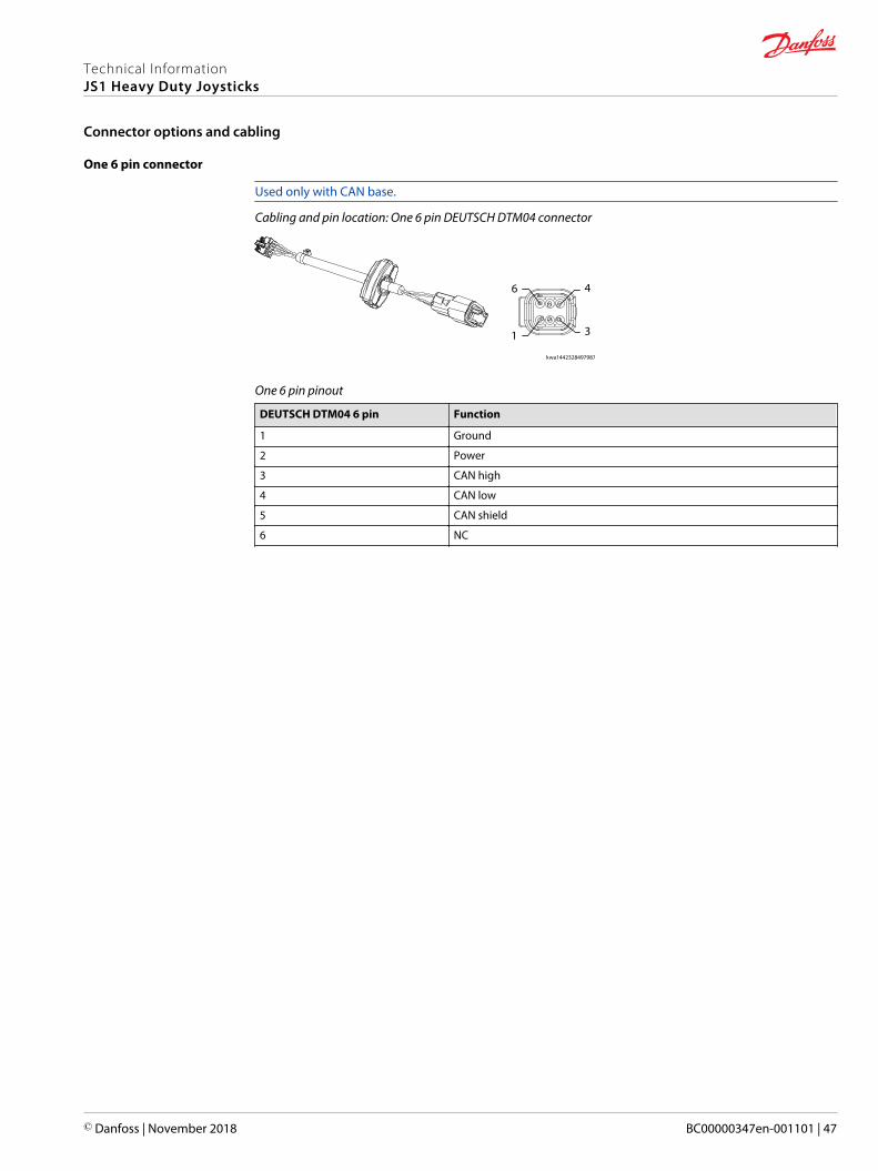
Two 12 pin and one 6 pin connectors
Used only on PVE Extended base.
Cabling and pin location: Two 12 pin and one 6 pin DEUTSCH DTM04 connectors
12
1
7
6
12
1
7
6
6
1
4
3
kwa1454871825360
Extended, 12 pin A pinout (Gray)
DEUTSCH DTM04 12 PIN PVE Extended Analog Cat 1 Analog Cat 3
1 Ground GND GND_ANA1
2 Power PWR_ANA PWR_ANA1 (+5V only)
3 CAN high Y1 (Prop 1) Y1 (Prop 1)
4 CAN low X1 (Prop 2) X1 (Prop 2)
5 CAN shield Analog 3A Analog 3A
6 Proportional Y Analog 4A Analog 4A
7 Proportional X Button 1 Button 1
8 Proportional 3 Button 2 Button 2
9 Push 7 Button 3 Button 3
10 Push 8 Button 4 Button 4
11 PVE power (neutral switch) PWR_ANA PWR_ANA2 (+5V Only)
12 PVE power feedback GND GND_ANA2
Extended, 12 pin B pinout (Black)
DEUTSCH DTM04 12 PIN PVE Extended Analog Cat 1 Analog Cat 3
1 Direction Ya NC NC
2 Direction Yb NC NC
3 Direction Xa Y2 Y2
4 Direction Xb X2 X2
5 Direction 3A/Push 1 Analog 3B Analog 3B
6 Direction 3B/Push 2 Analog 4B Analog 4B
7 Proportional 4 Button 5 Button 5
8 Direction 4A/Push 3 Button 6 Button 6
9 Direction 4B/Push 4 Button 7 Button 7
10 Proportional 5 Button 8 / OPS Button 8 / OPS
11 Direction 5A/Push 5 Analog 5A Analog 5A
12 Direction 5B/Push 6 Analog 5B Analog 5B
Technical InformationJS1 Heavy Duty Joysticks
Connector options and cabling
50 | © Danfoss | November 2018 BC00000347en-001101

Extended, 6 pin pinout
DEUTSCH DTM04 6-pin PVE Analog Cat 1 Analog Cat 3
1 Power Button 9 Button 9
2 Push 9 Button 10 Button 10
3 Push 10 Button 11 Button 11
4 Push 11 Button 12 Button 12
5 Push 12 open open
6 NC NC NC
One 18 pin connector
Used only on CAN+ or CANalog base.
Cabling and pin location: One 18 pin DEUTSCH connector (DT16-18SB-K004)
13
1
18
6
zmf1490390716959
18 pin pinout
DEUTSCH 18 pin CAN+ function CANalog function
1 Ground Ground
2 Power Power
3 CAN Hi CAN Hi
4 CAN Lo CAN Lo
5 CAN Shield CAN Shield
6 Digital input 7 Not connected
7 Vref ground Reference ground
8 Vref +5V Reference +5V
9 Analog in 1 Grip analog 3a
10 Analog in 2 Grip analog 3b
11 Analog in 3 Grip analog 1a
12 Analog in 4 Grip analog 2a
13 Digital input 1 Grip analog 1b
14 Digital input 2 Grip analog 2b
15 Digital input 3 Proportional Y-axis 1
16 Digital input 4 Proportional X-axis 1
17 Digital input 5 Proportional Y-axis 2
18 Digital input 6 Proportional X-axis 2
Technical InformationJS1 Heavy Duty Joysticks
Connector options and cabling
© Danfoss | November 2018 BC00000347en-001101 | 51

One 25 pin SUB-D and one 6 pin connectors
Used only on PVE base, with PP2, PR2, STT, and STP grips as Prof 1 replacements.
Cabling and pin location: One 25 pin SUB-D and one 6 pin DEUTSCH DTM04 connectors; Code number:11173403-T
6
1
1
13
4
14
3
25
wew1481755641811
25 pin SUB-D pinout
25 pin SUB-D Function
1 PVE power (neutral switch)
2 PVE power (neutral switch)
3 Power
4 Direction 5a/Push 5
5 Proportional 3
6 Direction 3a/Push 1
7 Proportional Y
8 Proportional X
9 Direction Xa
10 PVE Power feedback
11 Direction Yb
12 Push 8
13 Push 7
14 PVE power (neutral switch)
15 Power
16 Power
17 Direction 5b/ Push 6
18 Proportional 4
19 Direction 3b/Push 2
20 Direction 4a/Push 3
21 Direction 4a/Push 4
22 Ground
23 Direction Xb
24 Direction Ya
25 NC
Technical InformationJS1 Heavy Duty Joysticks
Connector options and cabling
52 | © Danfoss | November 2018 BC00000347en-001101

6 pin DEUTSCH DTM04 pinout
6 pin DEUTSCH DTM04 Function
1 NC
2 NC
3 CAN high
4 CAN low
5 CAN shield
6 NC
Mating connectors bag assemblies
Danfoss connector bag assemblies part numbers (Must be ordered separately from joystick)
Description Danfoss part number
One 6 pin DEUTSCH connector 10101551
Two 6 pin DEUTSCH connectors 11177980
Two 12 pin DEUTSCH connectors (GRY/BLK) 10100945
Two 12 pin and One 6 pin DEUTSCH connectors (GRY/BLK)
11176538
DEUTSCH mating connector bag assemblies contents
Description 6 pin module 12 pin module (GRY) 12 pin module (BLK)
Crimp tool HDT-48-00 HDT-48-00 HDT-48-00
Contacts 0462-201-2031 0462-201-2031 0462-201-2031
Connector plug DTM06-6S,GRY DTMO6-12SA, GRY DTMO6-12SB, BLK
Wedge WM-6S WM-12S WM-12S
Strip length 3.96 to 5.54 mm(0.156 to 0.218 in)
3.96 to 5.54 mm(0.156 to 0.218 in)
3.96 to 5.54 mm(0.156 to 0.218 in)
Rear seal maximuminsulation OD
3.05 mm (0.120 in) 3.05 mm (0.120 in) 3.05 mm (0.120 in)
Sealing plugs 0413-204-2005 0413-204-2005 0413-204-2005
Technical InformationJS1 Heavy Duty Joysticks
Connector options and cabling
© Danfoss | November 2018 BC00000347en-001101 | 53

Cable assemblies
All cable assemblies for JS1-H are 185 mm from the bottom of the case to the end of the connector.
JS1-H cable length in millimeters
143.00
43.70
1kwa1458923139980
1. DEUTSCH DTM04 receptacle
Compatible mating cables available for different applications
Code no. 162B…. Length mm Plug type Type
6013 4000 Leads Vertical SUB-D
6014 4000 Leads Horizontal SUB-D
6015 500 Clipper –
6016 230 TRIM TRIO –
6017 230 Tabs PVRE compatibility
Technical InformationJS1 Heavy Duty Joysticks
Connector options and cabling
54 | © Danfoss | November 2018 BC00000347en-001101

Cable assemblies - first is vertical view, followed by horizontal views
kwa1385300991617
Technical InformationJS1 Heavy Duty Joysticks
Connector options and cabling
© Danfoss | November 2018 BC00000347en-001101 | 55

The product configuration model code specifies particular features when ordering the JS1-H. The modelcode begins with the product family name and the remaining fields are filled in to configure the productwith the desired features.
JS1-H base and grip model code fields
The configuration model code contains information relating to both base and grip features.
JS1-H Joystick product configuration model code
Base Grip Common
A B C D E F1 F2 G H1 H2 H3 H4 H5 H6 H7 H8 H9 H10 H11 H12 J1 J2 J3 J4 K
JS1H
Technical InformationJS1 Heavy Duty Joysticks
Product configuration model code
56 | © Danfoss | November 2018 BC00000347en-001101

JS1-H Base model code
JS1-H Joystick product configuration model code
Base Grip Common
A B C D E F1 F2 G H1 H2 H3 H4 H5 H6 H7 H8 H9 H10 H11 H12 J1 J2 J3 J4 K
JS1H
A—Product family
Code Description
JS1H Family name
B—Operational axis
Code Description
NN No base
XY Bi-directional: X and Y-axis
NY Uni-directional: Only Y-axis
XN Uni-directional: Only X-axis
NF Single Axis: Frictional Y-axis
XF Bi-directional: X Spring Return, Y Frictional
C—Shaft position, sensing output
Code Description
NNN No base
NN2 No base, no connectors on wires
CJP CAN J1939 with potentiometer
CJH CAN J1939 with Hall effect
CPP CANopen with potentiometer
CPH CANopen with Hall effect
CSP CAN Analog, J1939 with potentiometer
CSH CAN Analog, J1939 with Hall effect
CTP CAN Analog, Open with potentiometer
CTH CAN Analog, Open with Hall effect
CLP CAN+ J1939 with potentiometer
CLH CAN+ J1939 with Hall effect
CMP CAN+ Open with potentiometer
CMH CAN+ Open with Hall effect
PSP PVE Standard base with potentiometer
PSH PVE Standard base with Hall effect
PEH PVE Extended base with Hall effect
PEP PVE Extended base with potentiometer
PBH Analog Category 1 with Hall effect
PRH PRH Analog Category 3 with Hall effect
Technical InformationJS1 Heavy Duty Joysticks
Product configuration model code
© Danfoss | November 2018 BC00000347en-001101 | 57

D—Centering spring
Code Description
N No base
S Standard spring force
H Heavy spring force
A Friction 0.8 Nm, Center 1.5 Nm
B Friction 0.8 Nm, Center 2.0 Nm
C Friction 1.6 Nm, Center 3.0 Nm
The following table only applies when using XF base.
Code Description
E Friction 0.8 Nm, Center 1.5 Nm, Standard spring force
J Friction 0.8 Nm, Center 1.5 Nm, Heavy spring force
E—CAN
Code Description
NNN Analog (base and/or grip)
C10 Node ID 10, 250kbs
C13 Node ID 13, 250kbs
C16 Node ID 16, 250kbs
C33 Note ID 33, 250kbs
C34 Note ID 34, 250kbs
C35 Note ID 35, 250kbs
C36 Note ID 36, 250kbs
D90 Node ID 90, 500kbs
D93 Node ID 93, 500kbs
D96 Node ID 96, 500kbs
D9C Node ID 9C, 500kbs
C90 Node ID 90, 250kbs
C93 Node ID 93, 250kbs
C96 Node ID 96, 250kbs
C9C Node ID 9C, 250kbs
B10 Node ID 10, 125kbs
B13 Node ID 13, 125kbs
B16 Node ID 16, 125kbs
B1C Node ID 1C, 125kbs
C1C Node ID 1C, 250kbs
C71 Replace of NodeID: N71
C72 Replace of NodeID: N72
F1—Mounting
Code Description
N No base
T Top mount
Technical InformationJS1 Heavy Duty Joysticks
Product configuration model code
58 | © Danfoss | November 2018 BC00000347en-001101

Grip model code
JS1-H Joystick product configuration model code
Base Grip Common
A B C D E F1 F2 G H1 H2 H3 H4 H5 H6 H7 H8 H9 H10 H11 H12 J1 J2 J3 J4 K
JS1H
F2—Grip type
Code Description
HR1 Horizontal grip
HP1 IP 66 version of HR1
ST2 Medium straight grip
SP2 IP 66 version of ST2
PR2 Prof1 version 2 grip
PP2 IP 66 version of PR2
ST7 Large straight grip
SP7 IP 66 version of ST7
PR7 Professional JS7000 grip
PP7 IP 66 version PR7
Select the grip that meets the needs of your application.
G—Left or right hand or ambidextrous
Code Description
L Left hand grip
R Right hand grip
U Ambidextrous grip (accommodates left and right hand)
Select the grip that meets the needs of your application.
H1—Defining of front plate
Code Description
N No button
B Black push button
R Red push button
Y Yellow push button
G Gray push button
L Green push button
W Blue push button
H White push button
1 Yellow push button - Dome Shape
2 Black push button - Dome Shape
3 Green push button - Dome Shape
4 Red push button - Dome Shape
5 Blue push button - Dome Shape
6 White push button - Dome Shape
P Roller, [position 1-2]
S Roller v-Lead, [position 1-2]
Technical InformationJS1 Heavy Duty Joysticks
Product configuration model code
© Danfoss | November 2018 BC00000347en-001101 | 59

H1—Defining of front plate (continued)
Code Description
V IP 66 Roller, [position 1-2]
F FNR [Black], [position 1-2]
T Toggle [Rocker], [position 1-2]
K FNR [Red], [position 1-2]
H2—Defining of front plate
Code Description
N No button
B Black push button
R Red push button
Y Yellow push button
G Gray push button
L Green push button
W Blue push button
H White push button
1 Yellow push button - Dome Shape
2 Black push button - Dome Shape
3 Green push button - Dome Shape
4 Red push button - Dome Shape
5 Blue push button - Dome Shape
6 White push button - Dome Shape
P Roller, [position 2-3]
S Roller v-Lead, [position 2-3]
V IP 66 Roller, [position 2-3]
F FNR [Black], [position 2-3]
T Toggle [Black], [position 2-3]
K FNR [Red], [position 2-3]
+ CustomerRefer to ST2 Faceplate options on page 14 andST7 Faceplate options on page 21
H3—Defining of front plate
Code Description
N No button
B Black push button
R Red push button
Y Yellow push button
G Gray push button
L Green push button
W Blue push button
H White push button
1 Yellow push button - Dome Shape
2 Black push button - Dome Shape
3 Green push button - Dome Shape
Technical InformationJS1 Heavy Duty Joysticks
Product configuration model code
60 | © Danfoss | November 2018 BC00000347en-001101

H3—Defining of front plate (continued)
Code Description
4 Red push button - Dome Shape
5 Blue push button - Dome Shape
6 White push button - Dome Shape
P Roller,[position 3-4]
S Roller v-Lead, [position 3-4]
V IP 66 Roller, [position 3-4]
F FNR [Black], [position 3-4]
T Toggle [Black], [position 3-4]
K FNR [Red], [position 3-4]
+ CustomerRefer to ST2 Faceplate options on page 14and ST7 Faceplate options on page 21
H4—Defining of front plate
Code Description
N No button
B Black push button
R Red push button
Y Yellow push button
G Gray push button
L Green push button
W Blue push button
H White push button
1 Yellow push button - Dome Shape
2 Black push button - Dome Shape
3 Green push button - Dome Shape
4 Red push button - Dome Shape
5 Blue push button - Dome Shape
6 White push button - Dome Shape
P Roller, [position 4-1]
S Roller v-Lead, [position 4-1]
V IP 66 Roller, [position 4-1]
F FNR [Black], [position 4-1]
T Toggle [Black], [position 4-1]
K FNR [Red], [position 4-1]
+ CustomerRefer to ST2 Faceplate options on page 14and ST7 Faceplate options on page 21
H5—Defining of front plate
Code Description
N No button
B Black push button
R Red push button
Technical InformationJS1 Heavy Duty Joysticks
Product configuration model code
© Danfoss | November 2018 BC00000347en-001101 | 61

H5—Defining of front plate (continued)
Code Description
Y Yellow push button
G Gray push button
L Green push button
W Blue push button
H White push button
1 Yellow push button - Dome Shape
2 Black push button - Dome Shape
3 Green push button - Dome Shape
4 Red push button - Dome Shape
5 Blue push button - Dome Shape
6 White push button - Dome Shape
+ CustomerRefer to ST2 Faceplate options on page 14and ST7 Faceplate options on page 21
H6—Defining grip side
Code Description
N No button
B Black push button
R Red push button
Y Yellow push button
G Gray push button
L Green push button
W Blue push button
H White push button
1 Yellow push button - Dome Shape
2 Black push button - Dome Shape
3 Green push button - Dome Shape
4 Red push button - Dome Shape
5 Blue push button - Dome Shape
6 White push button - Dome Shape
U Roller, [position 6-12]
Q Roller v-Lead, [position 6-12]
V IP 66 Roller, [position 6-12]
F FNR [Black], [position 6-12]
T Toggle [Black], [position 6-12]
K FNR [Red], [position 6-12]
+ CustomerRefer to ST2 Faceplate options on page 14and ST7 Faceplate options on page 21
Technical InformationJS1 Heavy Duty Joysticks
Product configuration model code
62 | © Danfoss | November 2018 BC00000347en-001101

H7—Defining grip side
Code Description
N No button
B Black push button
R Red push button
Y Yellow push button
G Gray push button
L Green push button
W Blue push button
H White push button
1 Yellow push button - Dome Shape
2 Black push button - Dome Shape
3 Green push button - Dome Shape
4 Red push button - Dome Shape
5 Blue push button - Dome Shape
6 White push button - Dome Shape
D Square Push Button - Operator Presence Switch
O Operator Presence Switch (PR2 and PP2 grips only)
U Roller, [position 7-8]
Q Roller v-Lead, [position 7-8]
V IP 66 Roller, [position 7-8]
H8—Defining grip side
Code Description
N No button
B Black push button
R Red push button
Y Yellow push button
G Gray push button
L Green push button
W Blue push button
H White push button
1 Yellow push button - Dome Shape
2 Black push button - Dome Shape
3 Green push button - Dome Shape
4 Red push button - Dome Shape
5 Blue push button - Dome Shape
6 White push button - Dome Shape
D Square push button - Operator Presence Switch
O Operator Presence Switch (ST7, SP7, ST2, SP2, HR1, and HP1 grips only)
A Operator Presence Switch (left hand PR7, PP7 grips only)
E Operator Presence Switch (right hand PR7, PP7 grips only)
Technical InformationJS1 Heavy Duty Joysticks
Product configuration model code
© Danfoss | November 2018 BC00000347en-001101 | 63

H9—Defining of back side
Code Description
N No button
B Black push button
R Red push button
Y Yellow push button
G Gray push button
L Green push button
W Blue push button
H White push button
1 Yellow push button - Dome Shape
2 Black push button - Dome Shape
3 Green push button - Dome Shape
4 Red push button - Dome Shape
5 Blue push button - Dome Shape
6 White push button - Dome Shape
K FNR [Red], [position 9-10]
H10—Defining grip side
Code Description
N No button
B Black push button
R Red push button
Y Yellow push button
G Gray push button
L Green push button
W Blue push button
H White push button
1 Yellow push button - Dome Shape
2 Black push button - Dome Shape
3 Green push button - Dome Shape
4 Red push button - Dome Shape
5 Blue push button - Dome Shape
6 White push button - Dome Shape
F FNR [Black], [position 10-11]
H11—Defining grip side
Code Description
N No button
B Black push button
R Red push button
Y Yellow push button
G Gray push button
L Green push button
W Blue push button
H White push button
Technical InformationJS1 Heavy Duty Joysticks
Product configuration model code
64 | © Danfoss | November 2018 BC00000347en-001101

H11—Defining grip side (continued)
Code Description
1 Yellow push button - Dome Shape
2 Black push button - Dome Shape
3 Green push button - Dome Shape
4 Red push button - Dome Shape
5 Blue push button - Dome Shape
6 White push button - Dome Shape
H12—Defining grip side
Code Description
N No button
B Black push button
R Red push button
Y Yellow push button
G Gray push button
L Green push button
W Blue push button
H White push button
1 Yellow push button - Dome Shape
2 Black push button - Dome Shape
3 Green push button - Dome Shape
4 Red push button - Dome Shape
5 Blue push button - Dome Shape
6 White push button - Dome Shape
K FNR [Red], [position 12]
J1—Grip color
Code Description
N No grip
G HR1 and PR7 grip
B ST2, ST7 and PR2 grip
J2—Color band
Code Description
N No color band
Y Yellow color band
B Black color band
R Red color band
Related reference
Technical InformationJS1 Heavy Duty Joysticks
Product configuration model code
© Danfoss | November 2018 BC00000347en-001101 | 65

Common model code
JS1-H Joystick product configuration model code
Base Grip Common
A B C D E F1 F2 G H1 H2 H3 H4 H5 H6 H7 H8 H9 H10 H11 H12 J1 J2 J3 J4 K
JS1H
J3—Cable
Code Description
N No cable
G CAN cable with 1 x 6 pin DEUTSCH connector
H CAN cable with 2 x 6 pin DEUTSCH connector
J CANalog cable with 18 pin DEUTSCH connector
L PVE cable with 12+12+6 pin DEUTSCH connector
K PVE cable with 12+12 pin DEUTSCH connector
T PVE cable with SUB-D 25 + 6 pin DEUTSCH connector
Q CAN+ cable with 18 pin DEUTSCH connector
J4—Kit and extension cable
Code Description
N No kit
B Adapter Plate for JS7000
C JS6000 bottom mount adapter
K—Software or settings
Code Description
NN No software or settings
Technical InformationJS1 Heavy Duty Joysticks
Product configuration model code
66 | © Danfoss | November 2018 BC00000347en-001101

Joystick safety critical functions
For a system to operate safely it must be able to differentiate between commanded and uncommandedinputs. Take steps to detect and manage joystick and system failures that may cause an erroneousoutput.
For safety critical functions Danfoss recommends you use an independent momentary action systemenable switch. You can incorporate this switch into the joystick as an operator presence switch or can bea separate foot or hand operated momentary switch. Disable all joystick functions that the joystickcontrols when this switch is released.
Ensure the control system looks for the appropriate system enable switch input before the joystick isdisplaced from its neutral position. Enable functions only after receiving this input.
Applications using CAN joysticks should continuously monitor for the presence of the CAN messages onperiodic basis. Messages are to be checked frequently enough for the system or operator to react if theCAN messages lose priority or are no longer received.
JS1 Heavy Duty Joystick critical mounting
JS1 Heavy Duty Joysticks are intended to be mounted in an upright position. Failure to mount properlycould result in erroneous Out of Neutral signals.
JS1-H mounted in upright position
Machine wiring guidelines
W Warning
Unintended movement of the machine or mechanism may cause injury to the technician or bystanders.Improperly protected power input lines against over current conditions may cause damage to thehardware. Properly protect all power input lines against over-current conditions. To protect againstunintended movement, secure the machine.
C Caution
Unused pins on mating connectors may cause intermittent product performance or premature failure.Plug all pins on mating connectors.
Technical InformationJS1 Heavy Duty Joysticks
Product installation
© Danfoss | November 2018 BC00000347en-001101 | 67

• Protect wires from mechanical abuse, run wires in flexible metal or plastic conduits.• Use 85˚ C (185˚ F) wire with abrasion resistant insulation and 105˚ C (221˚ F) wire should be
considered near hot surfaces.• Use a wire size that is appropriate for the module connector.• Separate high current wires such as solenoids, lights, alternators or fuel pumps from sensor and other
noise-sensitive input wires.• Run wires along the inside of, or close to, metal machine surfaces where possible, this simulates a
shield which will minimize the effects of EMI/RFI radiation.• Do not run wires near sharp metal corners, consider running wires through a grommet when
rounding a corner.• Do not run wires near hot machine members.• Provide strain relief for all wires.• Avoid running wires near moving or vibrating components.• Avoid long, unsupported wire spans.• Ground electronic modules to a dedicated conductor of sufficient size that is connected to the
battery (-).• Power the sensors and valve drive circuits by their dedicated wired power sources and ground
returns.• Twist sensor lines about one turn every 10 cm (4 in).• Use wire harness anchors that will allow wires to float with respect to the machine rather than rigid
anchors.
Technical InformationJS1 Heavy Duty Joysticks
Product installation
68 | © Danfoss | November 2018 BC00000347en-001101

Joysticks CAN J1939 protocol option on page 70
SAE J1939 basic joystick message on page 71
SAE J1939 extended joystick message on page 76
SAE J1939 error (DM1) messages on page 78
Technical InformationJS1 Heavy Duty Joysticks
Appendix: CAN J1939 protocol
© Danfoss | November 2018 BC00000347en-001101 | 69

Joysticks CAN J1939 protocol option
Joysticks CAN J1939 protocol option designated as model code CAN and broadcast two J1939 messagesto communicate the device information. The two messages are:• Basic Joystick Message 1 (BJM1)• Extended Joystick Message (EJM1)
Technical InformationJS1 Heavy Duty Joysticks
Appendix: CAN J1939 protocol
70 | © Danfoss | November 2018 BC00000347en-001101

SAE J1939 basic joystick message
The JS1-H joystick uses the SAE J1939 basic joystick message to transfer information about the measuredstatus of the X-axis and Y-axis of a joystick, the state of the switches on the joystick grip, and the state ofexternal to the joystick digital inputs.
Basic joystick message structure
Basic messagenumber
Priority Base parameterGroup number(PGN)
Protocol Data Unit(PDU) format
PDU specific Source address Data field
Dec hex Dec hex Dec hex Dec hex
1 3 64982 FDD6 253 FD 214 D6 * * 8 bytes
3 3 64986 FDDA 253 FD 218 DA * * 8 bytes* Depends on position specified in master model code.
• Message transmission rate: 20 ms• CAN bus baud rate: 250kbps
The resulting SAE J1939 basic joystick message PGN on the CAN bus is:
0xCFDD6 * * or 0xCFDDA * *
* = joystick source address (hex)
Data field
The data field contains the joystick’s output information. SAE J1939 data fields contain 8 bytes of data.
Information in the data field
Byte# 0 1 2 and so on
Bit# 1 2 3 4 5 6 7 8 1 2 3 4 5 6 7 8 1 2 3 4 5 6 7 8
Technical InformationJS1 Heavy Duty Joysticks
Appendix: CAN J1939 protocol
© Danfoss | November 2018 BC00000347en-001101 | 71

JS1-H Basic joystick message data field descriptions
Basic joystick message parameters and data field locations
Start position(byte/bit)
Length(bits)
Parameter name
0/1 2 Joystick X-axis neutral position status
0/3 2 Joystick X-axis lever left negative position status
0/5 2 Joystick X-axis lever right positive position status
0/7 through 1/1-8 10 Joystick X-axis position (Byte 0 Bit 7 is LSB. Byte 1 Bit 8 is MSB)
2/1 2 Joystick Y-axis neutral position status
2/3 2 Joystick Y-axis lever back negative position
2/5 2 Joystick Y-axis lever forward positive position
2/7 through 3/1-8 10 Joystick Y-axis position (Byte 2 Bit 7 is LSB. Byte 3 Bit 8 is MSB)
4/5 2 Joystick Y-axis detent position status
4/7 2 Joystick X-axis detent position status
5/1 2 Grip button 4 pressed status
5/3 2 Grip button 3 pressed status
5/5 2 Grip button 2 pressed status
5/7 2 Grip button 1 pressed status
6/1 2 Grip button 8 pressed status
6/3 2 Grip button 7 pressed status
6/5 2 Grip button 6 pressed status
6/7 2 Grip button 5 pressed status
7/1 2 Grip button 12 pressed status
7/3 2 Grip button 11 pressed status
7/5 2 Grip button 10 presses status
7/7 2 Grip button 9 pressed status
Data field example 1
Byte 0
Bit 8 7 6 5 4 3 2 1
The 2 LSB* of X-axisposition status
X-axis lever right positivestatus
X-axis lever left negativeposition status
X-axis neutral positionstatus
* Least Significant Bit.
Data field example 2
Byte 1
Bit 8 7 6 5 4 3 2 1
MSB* X-axis position* Most Significant Bit.
Technical InformationJS1 Heavy Duty Joysticks
Appendix: CAN J1939 protocol
72 | © Danfoss | November 2018 BC00000347en-001101

Data field example 3
Byte 2
Bit 8 7 6 5 4 3 2 1
The 2 LSB* of X-axisposition status
X-axis lever forwardpositive status
Y-axis lever back negativeposition status
Y-axis neutral positionstatus
* Least Significant Bit.
Joystick X-axis neutral position status
Reports when the current joystick position is in the neutral position for the X-axis of travel.
Information in the data field
Bit status Remarks
00 Not in neutral position
01 In neutral position
10 Error indicator
11 Not available
Joystick X-axis handle left negative position status
Reports when the current joystick position is on the negative travel side (back, left, counterclockwise,down) relative to the neutral position for the X-axis.
Information in the Data Field
Bit status Remarks
00 Not on negative side of neutral
01 On negative side of neutral
10 Error indicator
11 Not available
Joystick X-axis handle right positive position status
Reports when the current joystick position is on the positive travel side (forward, right, clockwise, up)relative to the neutral position for the X-axis.
Information in the data field
Bit status Remarks
00 Not on positive side of neutral
01 On positive side of neutral
10 Error indicator
11 Not available
Joystick X-axis position status
This is the position of the joystick in the relative motion of travel from the neutral position. The positionvalue of 0 is always neutral. The output range of the joystick handle at the end of travel is factory setaccording to the option specified in the electrical interface options section of the master model code.
The master model code specifies that the full-scale output at the end of each linear zone will be 1000counts.
Technical InformationJS1 Heavy Duty Joysticks
Appendix: CAN J1939 protocol
© Danfoss | November 2018 BC00000347en-001101 | 73

W Warning
Potential uncommanded machine movement. Per the SAE J1939-71 standard:• if the joystick internal diagnostics detect a shaft position measurement error, the joystick output will
be set to a value of 1022 counts regardless of shaft position.• if a specific joystick axis is not available, the basic joystick message for the unavailable axis will
indicate an output value of 1023 counts.Ensure application software recognizes these conditions to avoid the possibility of unintended machinemotion.
Joystick Y-axis neutral position status
Reports when the current joystick position is in the neutral position for the Y-axis of travel.
Information in the data field
Bit status Remarks
00 Not in neutral position
01 In neutral position
10 Error indicator
11 Not available
Joystick Y-axis handle back negative position status
Reports when the current joystick position is on the negative travel side (back, left, counterclockwise,down) relative to the neutral position for the Y-axis.
Information in the data field
Bit status Remarks
00 Not on negative side of neutral
01 On negative side of neutral
10 Error indicator
11 Not available
Joystick Y-axis handle forward positive position status
Reports when the current joystick position is on the positive travel side (forward, right, clockwise, up)relative to the neutral position for the Y-axis.
Information in the data field
Bit status Remarks
00 Not on positive side of neutral
01 On positive side of neutral
10 Error indicator
11 Not available
Joystick Y-axis position status
This is the position of the joystick in the relative motion of travel from the neutral position. The positionvalue of 0 is always neutral. The output range of the joystick handle at the end of travel is factory setaccording to the option specified in the electrical interface options section of the master model code.
Technical InformationJS1 Heavy Duty Joysticks
Appendix: CAN J1939 protocol
74 | © Danfoss | November 2018 BC00000347en-001101

The master model code specifies that the full-scale output at the end of each linear zone will be 1000counts.
W Warning
Potential uncommanded machine movement. Per the SAE J1939-71 standard:• if the joystick internal diagnostics detect a shaft position measurement error, the joystick output will
be set to a value of 1022 counts regardless of shaft position.• if a specific joystick axis is not available, the basic joystick message for the unavailable axis will
indicate an output value of 1023 counts.Ensure application software recognizes these conditions to avoid the possibility of unintended machinemotion.
Joystick button 1-8 pressed status
Joystick button 1-8 pressed status
Bit status Remarks
00 Button not pressed
01 Button pressed
10 Error indicator
11 Not available (no button installed)
Technical InformationJS1 Heavy Duty Joysticks
Appendix: CAN J1939 protocol
© Danfoss | November 2018 BC00000347en-001101 | 75

SAE J1939 extended joystick message
The JS1-H joystick uses the SAE J1939 extended joystick message to transfer information about themeasured status of up to 3 additional proportional input functions on the joystick grip, and external-to-the-joystick analog inputs. The joystick base X and Y-axis information is available in the basic joystickmessage.
Extended joystick message structure
Messagenumber
Priority Base PGN PDU format PDU specific Source address Data field
Dec hex Dec hex Dec hex Dec hex
1 3 64983 FDD7 253 FD 215 D7 The source addressdepends on positionspecified in mastermodel code.
8 bytes
3 3 64987 FDDB 253 FD 219 DB The source addressdepends on positionspecified in mastermodel code.
8 bytes
Message transmission rate: 20 ms
CAN bus baud rate: 250kbps
The resulting SAE J1939 extended joystick message PGN on the CAN bus is:
0xCFDD7 * * or 0xCFDDB * *
* = joystick source address (hex)
Extended joystick message parameters and data field descriptions
Extended joystick message parameters and data field locations
Start position(Byte/Bit)
Length(Bits)
Parameter name
0/1 2 Grip X-axis neutral position status
0/3 2 Grip X-axis lever left negative position status
0/5 2 Grip X-axis lever right positive position status
0/7 through 1/1-8 10 Grip X-axis position
2/1 2 Grip Y-axis neutral position status
2/3 2 Grip Y-axis lever back negative position
2/5 2 Grip Y-axis lever forward positive position
2/7 through 3/1-8 10 Grip Y-axis position
6/5 2 Grip Y-axis detent position status-not available
6/7 2 Grip X-axis detent position status-not available
Data field descriptions and output ranges for extended joystick messages are similar to those for base X-axis and Y-axis basic joystick messages.
Grip proportional input naming convention
Proportional input location Extended joystick message designation
Horizontal orientation, top X-axis
Horizontal orientation, bottom Y-axis
Technical InformationJS1 Heavy Duty Joysticks
Appendix: CAN J1939 protocol
76 | © Danfoss | November 2018 BC00000347en-001101
Grip proportional input naming convention (continued)
Proportional input location Extended joystick message designation
Vertical orientation, left side X-axis
Vertical orientation, right side Y-axis
Technical InformationJS1 Heavy Duty Joysticks
Appendix: CAN J1939 protocol
© Danfoss | November 2018 BC00000347en-001101 | 77

SAE J1939 error (DM1) messages
SAE J1939 DM1 error messages are supported. Suspect Parameter Number (SPN) and Failure ModeIdentifier (FMI) information are in the following tables.
Failure: Voltage too high
Message Axis SPN FMI
BJM1 X 2660 3
BJM1 Y 2661 3
BJM1 Grip X 2662 3
BJM1 Grip Y 2663 3
BJM1 Grip Theta 2664 3
Failure: Voltage too low
Message Axis SPN FMI
BJM1 X 2660 4
BJM1 Y 2661 4
BJM1 Grip X 2662 4
BJM1 Grip Y 2663 4
BJM1 Grip Theta 2664 4
Failure: Input not calibrated
Message Axis SPN FMI
BJM1 X 2660 13
BJM1 Y 2661 13
BJM1 Grip X 2662 13
BJM1 Grip Y 2663 13
BJM1 Grip Theta 2664 13
Failure: Redundant input failure
Message Axis SPN FMI
BJM1 X 2660 14
BJM1 Y 2661 14
BJM1 Grip X 2662 14
BJM1 Grip Y 2663 14
BJM1 Grip Theta 2664 14
SAE J1939 dynamic addressing is not supported, since the joystick source addresses are hard-coded(static). However, there is SAE J1939 address claiming protocol compliance. In the unlikely event anothernode on the SAE J1939 bus claims an identical source address to the joystick, the joystick may ceasecommunication on the bus, depending on the message priority on the other node.
Technical InformationJS1 Heavy Duty Joysticks
Appendix: CAN J1939 protocol
78 | © Danfoss | November 2018 BC00000347en-001101

CANopen Object Dictionary for JS1-H joysticks on page 80
Parameter/variable index - JS1-H CAN, JS1-H CANalog on page 81
Parameter/variable index - JS1-H CAN+ on page 93
Error handling on page 105
Technical InformationJS1 Heavy Duty Joysticks
Appendix: CAN+ and CANopen protocol
© Danfoss | November 2018 BC00000347en-001101 | 79
CANopen Object Dictionary for JS1-H joysticks
To access the CANopen Object Dictionary go to http://www.powersolutions.danfoss.com/products/electronic-components/Joysticks/, then under Download find CANopen EDS under the JS1-H.
In order to access an Entry within an Object, the Service Data Object (SDO) is used. The Initiate SDODownload/Upload protocol and the Upload SDO Segment protocol (used when data type isVISIBLE_STRING) are supported. Each Object has an Index and a Name. For each Entry within an Objectthere is a Sub-Index followed by a Name and a Description (if applicable).
The different Data types of an Entry can be as follows:• U32 (UNSIGNED32), U16 (UNSIGNED16) or U8 (UNSIGNED8)• S32 (INTEGER32), S16 (INTEGER16) or S8 (INTEGER8)• STR (VISIBLE_STRING)• NEUTRAL_STATE (2 bit state value)
The Access of an Entry can be as follows:• ro (Read Only)• rw (Read Write)• wo (Write Only)• const
The minimum and maximum value of an Entry is also specified where applicable. This does not mean thatthere is a check within the joystick that the written value is within the value range, for example, the Useris responsible to write a value within the value range. It should also be observed that the Default value ofan Entry may not be true for all applications. The Unit/Scale gives either the unit of the value and/or thescaling used where applicable.
CANopen Baud Rate and Node ID setting
Baud rate and Node ID may be set using the Danfoss PLUS+1® Service Tool. Additionally, the parameterscan be set using the CANopen LSS protocol.
CiA® 305: Layer Setting Services (LSS)
LSS distinguishes between an LSS master (typically residing in the host controller) and the LSS slaves. LSSenables the LSS master to modify the LSS slaves’ CANopen node-ID and to switch the entire networkfrom one data rate to another. LSS utilizes exactly two CAN frames. The CAN data frame 7E5h carries thecommand from the LSS master to one or several LSS slaves. The CAN frame 7E4h is used to provide theresponse(s) to the LSS master. LSS is specified in the document CiA 305.
Technical InformationJS1 Heavy Duty Joysticks
Appendix: CAN+ and CANopen protocol
80 | © Danfoss | November 2018 BC00000347en-001101

Parameter/variable index - JS1-H CAN, JS1-H CANalog
40h Device type
Sub-index Name Description Data type Access Minimum Maximum Default Unit/Scale
0 NEUTRAL_STATE
2-bit Proportional Axis(Neutral State) data type.0x00 = Neutral0x01 = Out Of Neutral0x02 = Error0x03 = Not Available
U32 ro - - - -
1000h Device type
Sub-index Name Description Data type Access Minimum Maximum Default Unit/Scale
0 Device Type 01050191h: Joystick withoutdigital outputs
U32 const - - Seedescription
-
1001h Device register
Sub-index Name Description Data type Access Minimum Maximum Default Unit/Scale
0 Error Register Bit 0 (Generic): 1 in case ofan unknown errorBit 1 (Current): Always zeroBit 2 (Voltage): 1 in case of avoltage to high or lowBit 3 (Temperature): AlwayszeroBit 4 (Communication Error):Always zeroBit 5 (Device Profile Specific):Always zeroBit 6 (Reserved): Always zeroBit 7 (Manufacture-Specific):1 in case of an IIC gripcommunication error, or acalibration error
U8 ro - - - -
1003h Error log: Code
Sub-index Name Description Data type Access Minimum Maximum Default Unit/Scale
0h Log size The entry at sub-index 0contains the number ofactual errors that arerecorded starting at sub-index 1.Writing a zero to sub-index 0clears the error log.Writing a value other thanzero to sub-index 0 willresult in an abort message.
U8 rw 0 24 - -
1h Error 1 Code Every new error is stored atsub-index 1, the older onesmove down the list.
U32 ro 0 232-1 - -
2h Error 2 Code U32 ro 0 232-1 - -
3h Error 3 Code U32 ro 0 232-1 - -
4h Error 4 Code U32 ro 0 232-1 - -
5h Error 5 Code U32 ro 0 232-1 - -
Technical InformationJS1 Heavy Duty Joysticks
Appendix: CAN+ and CANopen protocol
© Danfoss | November 2018 BC00000347en-001101 | 81

1003h Error log: Code (continued)
Sub-index Name Description Data type Access Minimum Maximum Default Unit/Scale
6h Error 6 Code U32 ro 0 232-1 - -
7h Error 7 Code U32 ro 0 232-1 - -
8h Error 8 Code U32 ro 0 232-1 - -
9h Error 9 Code U32 ro 0 232-1 - -
Ah Error 10 Code U32 ro 0 232-1 - -
Bh Error 11 Code U32 ro 0 232-1 - -
Ch Error 12 Code U32 ro 0 232-1 - -
Dh Error 13 Code U32 ro 0 232-1 - -
Eh Error 14 Code U32 ro 0 232-1 - -
Fh Error 15 Code U32 ro 0 232-1 - -
10h Error 16 Code U32 ro 0 232-1 - -
11h Error 17 Code U32 ro 0 232-1 - -
12h Error 18 Code U32 ro 0 232-1 - -
13h Error 19 Code U32 ro 0 232-1 - -
14h Error 20 Code U32 ro 0 232-1 - -
15h Error 21 Code U32 ro 0 232-1 - -
16h Error 22 Code U32 ro 0 232-1 - -
17h Error 23 Code U32 ro 0 232-1 - -
18h Error 24 Code U32 ro 0 232-1 - -
1008h Manufacturer device name
Sub-index Name Description Data type Access Minimum Maximum Default Unit/Scale
0 ManufacturerDevice Name
JS1-H device family name.Returns “JOYSTICK”
STR Const - - - -
1009h Manufacturer hardware version
Sub-index Name Description Data type Access Minimum Maximum Default Unit/Scale
0 ManufacturerHardwareVersion
Hardware part number.The part number will bedifferent for joystick models.
STR Const - - - -
100Ah Manufacturer software version
Sub-index Name Description Data type Access Minimum Maximum Default Unit/Scale
0 ManufacturerSoftwareVersion
Software part number andversion.
STR Const - - - -
1014h COB-ID EMCY message
Sub-index Name Description Data type Access Minimum Maximum Default Unit/Scale
0 COB-ID EMCYMessage
Defines the COB-ID of theEMCY object.
U32 ro 0 232-1 80h+ NodeID
-
Technical InformationJS1 Heavy Duty Joysticks
Appendix: CAN+ and CANopen protocol
82 | © Danfoss | November 2018 BC00000347en-001101

1017h Producer heartbeat time
Sub-index Name Description Data type Access Minimum Maximum Default Unit/Scale
0 Producer Time in milliseconds on howoften the Joystick willtransmit a heartbeat.A value of 0 will disable theheartbeat.It requires a reboot for thevalue to take effect afterchange.
U16 rw 0 232-1 20 -
1018h Identity object
Sub-index Name Description Data type Access Minimum Maximum Default Unit/Scale
0 Number ofentries
U8 const - - 4 -
1 Vendor Id Returns the Vendor Id forJS1-H = 19h.
U32 const - - 19h -
2 ProductCode
U32 const - - 1h -
3 RevisionNumber
U32 const - - 10001h -
4 SerialNumber
Device serial number. U32 const - - - -
1200h Server SD01 parameters
Sub-index Name Description Data type Access Minimum Maximum Default Unit/Scale
0 Number ofentries
U8 const - - 2 -
1 COB-ID usedby SDO 1 rx
U32 ro 0 232-1 600h+ NodeId
-
2 COB-ID usedby SDO 1 tx
U32 ro 0 232-1 580h+ NodeId
-
1800h Transmit PD01 communication parameters
Sub-index Name Description Data type Access Minimum Maximum Default Unit/Scale
0 Number ofentries
U8 const - - 5 -
1 COB-ID usedby PDO1 Tx
U32 ro 0 232-1 180h+ NodeId + 230
-
2 TransmissionType
FEh: event driven(manufacturer specific)
U8 ro 0 255 FEh -
3 Inhibit Time The time is the minimuminterval for PDOtransmission.The value is defined asmultiple of 100microseconds.The value of 0 shall disablethe inhibit time.
U16 rw 0 216-1 0 ms/10
Technical InformationJS1 Heavy Duty Joysticks
Appendix: CAN+ and CANopen protocol
© Danfoss | November 2018 BC00000347en-001101 | 83

1800h Transmit PD01 communication parameters (continued)
Sub-index Name Description Data type Access Minimum Maximum Default Unit/Scale
4 Reserved Not implemented; a read orwrite access results in anSDO abort with abort code06090011h.
- - - - - -
5 Event Time The time is the maximuminterval for PDOtransmission.The value of 0 shall disablethe event timer, resulting inthe PDO not beingtransmitted.
U16 rw 0 216-1 20 ms
1801h Transmit PDO2 communication parameters
Sub-index Name Description Data type Access Minimum Maximum Default Unit/Scale
0 Number ofentries
U8 const - - 5 -
1 COB-ID usedby PDO2 Tx
U32 ro 0 232-1 280h + NodeId + 230
-
2 TransmissionType
FEh: event driven(manufacturer specific)
U8 ro 0 255 FEh -
3 Inhibit Time The time is the minimuminterval for PDOtransmission.The value is defined asmultiple of 100microseconds.The value of 0 shall disablethe inhibit time.
U16 rw 0 216-1 0 ms/10
4 Reserved Not implemented; a read orwrite access results in anSDO abort with abort code06090011h.
- - - - - -
5 Event Timer The time is the maximuminterval for PDOtransmission.The value of 0 shall disablethe event timer, resulting inthe PDO not beingtransmitted.
U16 rw 0 216-1 20 ms
1802h Transmit PDO3 communication parameters
Sub-index Name Description Data type Access Minimum Maximum Default Unit/Scale
0 Number ofentries
U8 const - - 5 -
1 COB-ID usedby PDO3 Tx
U32 ro 0 232-1 380h + NodeId + 230
-
2 TransmissionType
FEh: event driven(manufacturer specific)
U8 ro 0 255 FEh -
Technical InformationJS1 Heavy Duty Joysticks
Appendix: CAN+ and CANopen protocol
84 | © Danfoss | November 2018 BC00000347en-001101

1802h Transmit PDO3 communication parameters (continued)
Sub-index Name Description Data type Access Minimum Maximum Default Unit/Scale
3 Inhibit Time The time is the minimuminterval for PDOtransmission.The value is defined asmultiple of 100microseconds.The value of 0 shall disablethe inhibit time.
U16 rw 0 216-1 0 ms/10
4 Reserved Not implemented; a read orwrite access results in anSDO abort with abort code06090011h.
- - - - - -
5 Event Timer The time is the maximuminterval for PDOtransmission.The value of 0 shall disablethe event timer, resulting inthe PDO not beingtransmitted.
U16 rw 0 216-1 20 ms
1A00h Transmit PD01 map parameters
Sub-index Name Description Data type Access Minimum Maximum Default Unit/Scale
0 Number ofMappedApplicationsObjects inPDO1Tx
U8 ro 0 49 49 -
1 Mapping forProportionalMemoryFreeze Status
Example: 6000h:1gives value=60000108hwhere index=6000hsub-index=01hdata type=08h (8bits)
U32 ro 0 232-1 60000108h -
2 Mapping forButton 1
Button status U32 ro 0 232-1 60200101h -
3 Mapping forButton 2
Button status U32 ro 0 232-1 60200201h -
4 Mapping forButton 3
Button status U32 ro 0 232-1 60200301h -
5 Mapping forButton 4
Button status U32 ro 0 232-1 60200401h -
6 Mapping forButton 5
Button status U32 ro 0 232-1 60200401h -
7 Mapping forButton 6
Button status U32 ro 0 232-1 60200601h -
8 Mapping forButton 7
Button status U32 ro 0 232-1 60200701h -
9 Mapping forButton 8
Button status U32 ro 0 232-1 60200801h -
10 Mapping forButton 9
Button status U32 ro 0 2232-1 60200901h -
11 Mapping forButton 10
Button status U32 ro 0 232-1 60200A01h -
12 Mapping forButton 11
Button status U32 ro 0 232-1 60200B01h -
Technical InformationJS1 Heavy Duty Joysticks
Appendix: CAN+ and CANopen protocol
© Danfoss | November 2018 BC00000347en-001101 | 85

1A00h Transmit PD01 map parameters (continued)
Sub-index Name Description Data type Access Minimum Maximum Default Unit/Scale
13 Mapping forButton 12
Button status U32 ro 0 232-1 60200C01h -
14 Mapping forButton 13
Button status U32 ro 0 232-1 60200D01h -
15 Mapping forButton 14
Button status U32 ro 0 232-1 60200E01h -
16 Mapping forButton 15
Button status U32 ro 0 232-1 60200F01h -
17 Mapping forButton 16
Button status U32 ro 0 232-1 60201001h -
18 Mapping forButton 17
Button status U32 ro 0 232-1 60201101h -
19 Mapping forButton 18
Button status U32 ro 0 232-1 60201201h -
20 Mapping forButton 19
Button status U32 ro 0 232-1 60201301h -
21 Mapping forButton 20
Button status U32 ro 0 232-1 60201401h -
22 Mapping forButton 21
Button status U32 ro 0 232-1 60201501h -
23 Mapping forButton 22
Button status U32 ro 0 232-1 60201601h -
24 Mapping forButton 23
Button status U32 ro 0 232-1 60201701h -
25 Mapping forButton 24
Button status U32 ro 0 232-1 60201801h -
26 Reserved Example: 6000h:2gives value=60000208hwhere index=6000hsub-index=02h datatype=08h (8 bits)
U32 ro 0 232-1 60000208h -
27 Mapping forButton 1
Button enabled U32 ro 0 232-1 60201901h -
28 Mapping forButton 2
Button enabled U32 ro 0 232-1 60201A01h -
29 Mapping forButton 3
Button enabled U32 ro 0 232-1 60201B01h -
30 Mapping forButton 4
Button enabled U32 ro 0 232-1 60201C01h -
31 Mapping forButton 5
Button enabled U32 ro 0 232-1 60201D01h -
32 Mapping forButton 6
Button enabled U32 ro 0 232-1 60201E01h -
33 Mapping forButton 7
Button enabled U32 ro 0 232-1 60201F01h -
34 Mapping forButton 8
Button enabled U32 ro 0 232-1 60202001h -
35 Mapping forButton 9
Button enabled U32 ro 0 232-1 60202101h -
36 Mapping forButton 10
Button enabled U32 ro 0 232-1 60202201h -
37 Mapping forButton 11
Button enabled U32 ro 0 232-1 60202301h -
Technical InformationJS1 Heavy Duty Joysticks
Appendix: CAN+ and CANopen protocol
86 | © Danfoss | November 2018 BC00000347en-001101

1A00h Transmit PD01 map parameters (continued)
Sub-index Name Description Data type Access Minimum Maximum Default Unit/Scale
38 Mapping forButton 12
Button enabled U32 ro 0 232-1 60202401h -
39 Mapping forButton 13
Button enabled U32 ro 0 232-1 60202501h -
40 Mapping forButton 14
Button enabled U32 ro 0 232-1 60202601h -
41 Mapping forButton 15
Button enabled U32 ro 0 232-1 60202701h -
42 Mapping forButton 16
Button enabled U32 ro 0 232-1 60202801h -
43 Mapping forButton 17
Button enabled U32 ro 0 232-1 60202901h -
44 Mapping forButton 18
Button enabled U32 ro 0 232-1 60202A01h -
45 Mapping forButton 19
Button enabled U32 ro 0 232-1 60202B01h -
46 Mapping forButton 20
Button enabled U32 ro 0 232-1 60202C01h -
47 Mapping forButton 21
Button enabled U32 ro 0 232-1 60202D01h -
48 Mapping forButton 22
Button enabled U32 ro 0 232-1 60202E01h -
49 Mapping forButton 23
Button enabled U32 ro 0 232-1 60202F01h -
50 Mapping forButton 24
Button enabled U32 ro 0 232-1 60203001h -
1A01h Transmit PD02 map parameters
Sub-index Name Description Data type Access Minimum Maximum Default Unit/Scale
0 Number ofMappedApplicationsObjects inPDO2Tx
U8 ro 0 6 6 -
1 Mapping forX-AxisProportional
Example: 6401h:1gives value=64010110hwhere index=6401hsub-index=01hdata type=10h (16 bits)
U32 ro 0 232-1 64010110h -
2 Mapping forY-AxisProportional
U32 ro 0 232-1 64010210h -
3 Reserved Example: 6405h:1gives value=64050110hwhere index=6405hsub-index=01hdata type=10h (16 bits)
U32 ro 0 232-1 64050110h -
4 Mapping forX-AxisNeutral State
Example: 6404h:1gives value=64040102hwhere index=6404hsub-index=01hdata type=02h (2 bits)
U32 ro 0 232-1 64040102h -
Technical InformationJS1 Heavy Duty Joysticks
Appendix: CAN+ and CANopen protocol
© Danfoss | November 2018 BC00000347en-001101 | 87

1A01h Transmit PD02 map parameters (continued)
Sub-index Name Description Data type Access Minimum Maximum Default Unit/Scale
5 Mapping forY-AxisNeutral State
U32 ro 0 232-1 64040202h -
6 Reserved Example: 6406h:1gives value=64060102hwhere index=6406hsub-index=01hdata type=02h (2 bits)
U32 ro 0 232-1 64060102h -
1A02h Transmit PD03 map parameters
Sub-index Name Description Data type Access Minimum Maximum Default Unit/Scale
0 Number ofMappedApplicationsObjects inPDO3Tx
U8 ro 0 6 6 -
1 Mapping forGrip 1Proportional
Example:6401h:1 givesvalue=64010310hwhereindex=6401hsub-index=03h datatype=10h (16 bits)
U32 ro 0 232-1 64010310h -
2 Mapping forGrip 2Proportional
U32 ro 0 232-1 64010410h -
3 Mapping forGrip 3Proportional
U32 ro 0 232-1 64010510h -
4 Mapping forGrip 1 AxisNeutral State
Example: 6404h:3gives value=64040302hwhere index=6404hsub-index=03hdata type=02h (2 bits)
U32 ro 0 232-1 64040302h -
5 Mapping forGrip 2 AxisNeutral State
U32 ro 0 232-1 64040402h -
6 Mapping forGrip 3 AxisNeutral State
U32 ro 0 232-1 64040502h -
Technical InformationJS1 Heavy Duty Joysticks
Appendix: CAN+ and CANopen protocol
88 | © Danfoss | November 2018 BC00000347en-001101

6000h Read input 8-bit
Sub-index Name Description Data type Access Minimum Maximum Default Unit/Scale
0 Number ofInputs 8-Bit
U8 ro 0 1 - -
1 ProportionalMemoryFreeze
*Not supportedMemory status for theproportional outputs.0: memory function off(release proportional values)1: memory functions on(freeze proportional values)
U8 ro 0 0 0 -
2 ProportionalMemoryFreeze
*Not supportedMemory status for theproportional outputs.0: memory function off(release proportional values)1: memory functions on(freeze proportional values)
U8 ro 0 0 0 -
6020h Read input bit (buttons)
Sub-index Name Description Data type Access Minimum Maximum Default Unit/Scale
0 Number ofInputs Bits
U8 ro 0 32 32 -
1 Freeze Bit 1 *Not supportedMemory status for theproportional outputs.0: memory function off(release proportional values)1: memory functions on(freeze proportional values)
U8 ro 0 0 0 -
2 Freeze Bit 2 *Not supported U8 ro 0 0 0 -
3 Freeze Bit 3 *Not supported U8 ro 0 0 0 -
4 Freeze Bit 4 *Not supported U8 ro 0 0 0 -
5 Freeze Bit 5 *Not supported U8 ro 0 0 0 -
6 Freeze Bit 6 *Not supported U8 ro 0 0 0 -
7 Freeze Bit 7 *Not supported U8 ro 0 0 0 -
8 Freeze Bit 8 *Not supported U8 ro 0 0 0 -
9 Button 1 0: Not Pressed1: Pressed
U8 ro 0 1 0 -
10 Button 2 See Button 1 (Sub Index 9) U8 ro 0 1 0 -
11 Button 3 See Button 1 (Sub Index 9) U8 ro 0 1 0 -
12 Button 4 See Button 1 (Sub Index 9) U8 ro 0 1 0 -
13 Button 5 See Button 1 (Sub Index 9) U8 ro 0 1 0 -
14 Button 6 See Button 1 (Sub Index 9) U8 ro 0 1 0 -
15 Button 7 See Button 1 (Sub Index 9) U8 ro 0 1 0 -
16 Button 8 See Button 1 (Sub Index 9) U8 ro 0 1 0 -
17 Button 9 See Button 1 (Sub Index 9) U8 ro 0 1 0 -
18 Button 10 See Button 1 (Sub Index 9) U8 ro 0 1 0 -
19 Button 11 See Button 1 (Sub Index 9) U8 ro 0 1 0 -
20 Button 12 See Button 1 (Sub Index 9) U8 ro 0 1 0 -
21 Button 13 See Button 1 (Sub Index 9) U8 ro 0 1 0 -
Technical InformationJS1 Heavy Duty Joysticks
Appendix: CAN+ and CANopen protocol
© Danfoss | November 2018 BC00000347en-001101 | 89

6020h Read input bit (buttons) (continued)
Sub-index Name Description Data type Access Minimum Maximum Default Unit/Scale
22 Button 14 See Button 1 (Sub Index 9) U8 ro 0 1 0 -
23 Button 15 See Button 1 (Sub Index 9) U8 ro 0 1 0 -
24 Button 16 See Button 1 (Sub Index 9) U8 ro 0 1 0 -
25 Button 17 See Button 1 (Sub Index 9) U8 ro 0 1 0 -
26 Button 18 See Button 1 (Sub Index 9) U8 ro 0 1 0 -
27 Button 19 See Button 1 (Sub Index 9) U8 ro 0 1 0 -
28 Button 20 See Button 1 (Sub Index 9) U8 ro 0 1 0 -
29 Button 21 See Button 1 (Sub Index 9) U8 ro 0 1 0 -
30 Button 22 See Button 1 (Sub Index 9) U8 ro 0 1 0 -
31 Button 23 See Button 1 (Sub Index 9) U8 ro 0 1 0 -
32 Button 24 See Button 1 (Sub Index 9) U8 ro 0 1 0 -
33 Button 1 0: Not Enabled1: Enabled
U8 ro 0 1 0 -
34 Button 2 See Button 1 (Sub Index 33) U8 ro 0 1 0 -
35 Button 3 See Button 1 (Sub Index 33) U8 ro 0 1 0 -
36 Button 4 See Button 1 (Sub Index 33) U8 ro 0 1 0 -
37 Button 5 See Button 1 (Sub Index 33) U8 ro 0 1 0 -
38 Button 6 See Button 1 (Sub Index 33) U8 ro 0 1 0 -
39 Button 7 See Button 1 (Sub Index 33) U8 ro 0 1 0 -
40 Button 8 See Button 1 (Sub Index 33) U8 ro 0 1 0 -
41 Button 9 See Button 1 (Sub Index 33) U8 ro 0 1 0 -
42 Button 10 See Button 1 (Sub Index 33) U8 ro 0 1 0 -
43 Button 11 See Button 1 (Sub Index 33) U8 ro 0 1 0 -
44 Button 12 See Button 1 (Sub Index 33) U8 ro 0 1 0 -
45 Button 13 See Button 1 (Sub Index 33) U8 ro 0 1 0 -
46 Button 14 See Button 1 (Sub Index 33) U8 ro 0 1 0 -
47 Button 15 See Button 1 (Sub Index 33) U8 ro 0 1 0 -
48 Button 16 See Button 1 (Sub Index 33) U8 ro 0 1 0 -
49 Button 17 See Button 1 (Sub Index 33) U8 ro 0 1 0 -
50 Button 18 See Button 1 (Sub Index 33) U8 ro 0 1 0 -
51 Button 19 See Button 1 (Sub Index 33) U8 ro 0 1 0 -
52 Button 20 See Button 1 (Sub Index 33) U8 ro 0 1 0 -
53 Button 21 See Button 1 (Sub Index 33) U8 ro 0 1 0 -
54 Button 22 See Button 1 (Sub Index 33) U8 ro 0 1 0 -
55 Button 23 See Button 1 (Sub Index 33) U8 ro 0 1 0 -
56 Button 24 See Button 1 (Sub Index 33) U8 ro 0 1 0 -
6401h Read analog inputs 16-Bit
Sub-index Name Description Data type Access Minimum Maximum Default Unit/Scale
0 Number ofAnalogInputs 16-Bit
U8 ro 0 10 - -
1 X-AxisProportional
S16 ro -1000 1000 0 %*10
2 Y-AxisProportional
S16 ro -1000 1000 0 %*10
Technical InformationJS1 Heavy Duty Joysticks
Appendix: CAN+ and CANopen protocol
90 | © Danfoss | November 2018 BC00000347en-001101

6401h Read analog inputs 16-Bit (continued)
Sub-index Name Description Data type Access Minimum Maximum Default Unit/Scale
3 Grip 1Proportional
S16 ro -1000 1000 0 %*10
4 Grip 2Proportional
S16 ro -1000 1000 0 %*10
5 Grip 3Proportional
S16 ro -1000 1000 0 %*10
6 Axis 5 S16 ro -1000 1000 0 %*10
7 Axis 6 S16 ro -1000 1000 0 %*10
8 Axis 7 S16 ro -1000 1000 0 %*10
9 Axis 8 S16 ro -1000 1000 0 %*10
10 Axis 9 S16 ro -1000 1000 0 %*10
6404h Manufacturer specific input 2-Bit
Sub-index Name Description Data type Access Minimum Maximum Default Unit/Scale
0 Number ofMfg SpecificInputs 2-Bit
U8 ro 0 10 - -
1 X-AxisProportionalNeutral State
U8 ro 0 3 0 00 – Neutral01 – Out ofNeutral10 – Error11 – NotAvailable
2 Y-AxisProportionalNeutral State
U8 ro 0 3 0 See SubIndex 1
3 Grip 1ProportionalNeutral State
U8 ro 0 3 0 See SubIndex 1
4 Grip 2ProportionalNeutral State
U8 ro 0 3 0 See SubIndex 1
5 Grip 3ProportionalNeutral State
U8 ro 0 3 0 See SubIndex 1
6 Axis 5Neutral State
U8 ro 0 3 0 See SubIndex 1
7 Axis 6Neutral State
U8 ro 0 3 0 See SubIndex 1
8 Axis 7Neutral State
U8 ro 0 3 0 See SubIndex 1
9 Axis 8Neutral State
U8 ro 0 3 0 See SubIndex 1
10 Axis 9Neutral State
U8 ro 0 3 0 See SubIndex 1
Technical InformationJS1 Heavy Duty Joysticks
Appendix: CAN+ and CANopen protocol
© Danfoss | November 2018 BC00000347en-001101 | 91

6405h Manufacturer specific reserved 16-Bit
Sub-index Name Description Data type Access Minimum Maximum Default Unit/Scale
0 Number ofMfg SpecificReserved 16-Bit
U16 ro 0 1 - -
1 Reserved 1 U16 ro 0 216-1 0
6406h Manufacturer specific reserved 2-Bit
Sub-index Name Description Data type Access Minimum Maximum Default Unit/Scale
0 Number ofMfg SpecificReserved 2-Bit
U8 ro 0 1 - -
1 Reserved 1 U8 ro 0 3 0
Technical InformationJS1 Heavy Duty Joysticks
Appendix: CAN+ and CANopen protocol
92 | © Danfoss | November 2018 BC00000347en-001101

Parameter/variable index - JS1-H CAN+
40h Device type
Sub-index Name Description Data type Access Minimum Maximum Default Unit/Scale
0 NEUTRAL_ST ATE 2-bit Proportional Axis (NeutralState) data type.0x00 = Neutral0x01 = Out Of Neutral0x02 = Error0x03 = Not Available
U32 ro = = = =
1000h Device type
Sub-index Name Description Data type Access Minimum Maximum Default Unit/Scale
0 Device Type 01050191h: Joystick without digitaloutputs
U32 const = = Seedescription
=
1001h Device register
Sub-index Name Description Data type Access Minimum Maximum Default Unit/Scale
0 Error Register Bit 0 (Generic): 1 in case of anunknown errorBit 1 (Current): Always zero Bit 2(Voltage): 1 in case of a voltage tohigh or lowBit 3 (Temperature): Always zeroBit 4 (Communication Error): AlwayszeroBit 5 (Device Profile Specific): AlwayszeroBit 6 (Reserved): Always zeroBit 7 (Manufacture-Specific): 1 incase of an IIC grip communicationerror, or a calibration error
U8 ro = = = =
1003h Error log: Code
Sub-index Name Description Data type Access Minimum Maximum Default Unit/Scale
0h Log size The entry at sub-index 0 containsthe number of actual errors that arerecorded starting at sub- index 1.Writing a zero to sub-index 0 clearsthe error log.Writing a value other than zero tosub-index 0 will result in an abortmessage.
U8 rw 0 24 = =
1h Error 1 Code Every new error is stored at sub-index 1, the older ones move downthe list.
U32 ro 0 232-1 = =
2h Error 1 Code U32 ro 0 232-1 = =
3h Error 1 Code U32 ro 0 232-1 = =
4h Error 1 Code U32 ro 0 232-1 = =
5h Error 1 Code U32 ro 0 232-1 = =
6h Error 1 Code U32 ro 0 232-1 = =
7h Error 1 Code U32 ro 0 232-1 = =
Technical InformationJS1 Heavy Duty Joysticks
Appendix: CAN+ and CANopen protocol
© Danfoss | November 2018 BC00000347en-001101 | 93

1003h Error log: Code (continued)
Sub-index Name Description Data type Access Minimum Maximum Default Unit/Scale
8h Error 1 Code U32 ro 0 232-1 = =
9h Error 1 Code U32 ro 0 232-1 = =
Bh Error 1 Code U32 ro 0 232-1 = =
Ch Error 1 Code U32 ro 0 232-1 = =
Dh Error 1 Code U32 ro 0 232-1 = =
Eh Error 1 Code U32 ro 0 232-1 = =
Fh Error 1 Code U32 ro 0 232-1 = =
10h Error 1 Code U32 ro 0 232-1 = =
11h Error 1 Code U32 ro 0 232-1 = =
12h Error 1 Code U32 ro 0 232-1 = =
13h Error 1 Code U32 ro 0 232-1 = =
14h Error 1 Code U32 ro 0 232-1 = =
15h Error 1 Code U32 ro 0 232-1 = =
16h Error 1 Code U32 ro 0 232-1 = =
17h Error 1 Code U32 ro 0 232-1 = =
18h Error 1 Code U32 ro 0 232-1 = =
1008h Manufacturer device name
Sub-index Name Description Data type Access Minimum Maximum Default Unit/Scale
0 Manufacturer DeviceName
JS1-H device family name. Returns“JOYSTICK”
STR Const = = = =
1009h Manufacturer hardware version
Sub-index Name Description Data type Access Minimum Maximum Default Unit/Scale
0 Manufacturer HardwareVersion
Hardware part number.The part number will be different forjoystick models.
STR Const = = = =
100Ah Manufacturer software version
Sub-index Name Description Data type Access Minimum Maximum Default Unit/Scale
0 Manufacturer SoftwareVersion
Software part number and version. STR Const = = = =
1014h COB-ID EMCY message
Sub-index Name Description Data type Access Minimum Maximum Default Unit/Scale
0 COB-ID EMCYMessage
Defines the COB-ID of the EMCYobject.
U32 ro 0 232-1 80h+Node ID
=
Technical InformationJS1 Heavy Duty Joysticks
Appendix: CAN+ and CANopen protocol
94 | © Danfoss | November 2018 BC00000347en-001101

1017h Producer heartbeat time
Sub-index Name Description Data type Access Minimum Maximum Default Unit/Scale
0 Producer Time in milliseconds on how oftenthe Joystick will transmit aheartbeat.A value of 0 will disable theheartbeat.It requires a reboot for the value totake effect after change.
U16 rw 0 232-1 20 =
1018h Identity object
Sub-index Name Description Data type Access Minimum Maximum Default Unit/Scale
0 Number of entries U8 Const = = 4 =
1 Vendor Id Returns the Vendor Id for JS1-H =19h.
U32 Const = = 19h =
2 Product Code U32 Const = = 1h =
3 Revision Number U32 Const = = 10001h =
4 Serial Number Device serial number. U32 Const = = = =
1200h Server SD01 parameters
Sub-index Name Description Data type Access Minimum Maximum Default Unit/Scale
0 Number of entries U8 Const = = 2 =
1 COB-ID used by SDO 1rx
U32 ro 0 232-1 600h+Node Id
=
2 COB-ID used by SDO 1tx
U32 ro 0 232-1 580h+Node Id
=
1800h Transmit PD01 communication parameters
Sub-index Name Description Data type Access Minimum Maximum Default Unit/Scale
0 Number of entries U8 Const = = 5 =
1 COB-ID used by PDO1Tx
U32 ro 0 232-1 180h+Node Id +230
=
2 Transmission Type FEh: event driven(manufacturer specific)
U8 ro 0 255 FEh =
3 Inhibit Time The time is the minimum interval forPDO transmission.The value is defined as multiple of100 microseconds.The value of 0 shall disable theinhibit time.
U16 rw 0 216-1 0 ms/10
4 Reserved Not implemented; a read or writeaccess results in an SDO abort withabort code 06090011h.
= = = = = =
5 Event Time The time is the maximum intervalfor PDO transmission.The value of 0 shall disable theevent timer, resulting in the PDOnot being transmitted.
U16 rw 0 216-1 20 ms
Technical InformationJS1 Heavy Duty Joysticks
Appendix: CAN+ and CANopen protocol
© Danfoss | November 2018 BC00000347en-001101 | 95

1801h Transmit PDO2 communication parameters
Sub-index Name Description Data type Access Minimum Maximum Default Unit/Scale
0 Number of entries U8 Const = = 5 =
1 COB-ID used by PDO2Tx
U32 ro 0 232-1 280h+Node Id +230
=
2 Transmission Type FEh: event driven(manufacturer specific)
U8 ro 0 255 FEh =
3 Inhibit Time The time is the minimum interval forPDO transmission.The value is defined as multiple of100 microseconds.The value of 0 shall disable theinhibit time.
U16 rw 0 216-1 0 ms/10
4 Reserved Not implemented; a read or writeaccess results in an SDO abort withabort code 06090011h.
= = 0 = = =
5 Event Time The time is the maximum intervalfor PDO transmission.The value of 0 shall disable theevent timer, resulting in the PDOnot being transmitted.
U16 rw 0 216-1 20 ms
1802h Transmit PDO3 communication parameters
Sub-index Name Description Data type Access Minimum Maximum Default Unit/Scale
0 Number of entries U8 Const = = 5 =
1 COB-ID used by PDO3Tx
U32 ro 0 232-1 380h+Node Id +230
=
2 Transmission Type FEh: event driven(manufacturer specific)
U8 ro 0 255 FEh =
3 Inhibit Time The time is the minimum interval forPDO transmission.The value is defined as multiple of100 microseconds.The value of 0 shall disable theinhibit time.
U16 rw 0 216-1 0 ms/10
4 Reserved Not implemented; a read or writeaccess results in an SDO abort withabort code 06090011h.
= = = = = =
5 Event Time The time is the maximum intervalfor PDO transmission.The value of 0 shall disable theevent timer, resulting in the PDOnot being transmitted.
U16 rw 0 216-1 20 ms
1803h Transmit PDO4 communication parameters
Sub-index Name Description Data type Access Minimum Maximum Default Unit/Scale
0 Number of entries U8 Const = = 5 =
1 COB-ID used by PDO3Tx
U32 ro 0 232-1 380h+Node Id +230
=
2 Transmission Type FEh: event driven(manufacturer specific)
U8 ro 0 255 FEh =
Technical InformationJS1 Heavy Duty Joysticks
Appendix: CAN+ and CANopen protocol
96 | © Danfoss | November 2018 BC00000347en-001101

1803h Transmit PDO4 communication parameters (continued)
Sub-index Name Description Data type Access Minimum Maximum Default Unit/Scale
3 Inhibit Time The time is the minimum interval forPDO transmission.The value is defined as multiple of100 microseconds.The value of 0 shall disable theinhibit time.
U16 rw 0 216-1 0 ms/10
4 Reserved Not implemented; a read or writeaccess results in an SDO abort withabort code 06090011h.
= = = = = =
5 Event Time The time is the maximum intervalfor PDO transmission.The value of 0 shall disable theevent timer, resulting in the PDOnot being transmitted.
U16 rw 0 216-1 20 ms
1A00h Transmit PD01 map parameters
Sub-index Name Description Data type Access Minimum Maximum Default Unit/Scale
0 Number of MappedApplications Objects inPDO1Tx
U8 ro 0 39 39 =
1 Mapping forProportional MemoryFreeze Status
Example: 6000h:1gives value=60000108hwhere index=6000hsub-index=01hdata type=08h (8bits)
U32 ro 0 0 60000108h
=
2 Mapping for Button 1 Button status U32 ro 0 1 60200101h
=
3 Mapping for Button 2 Button status U32 ro 0 1 60200201h
=
4 Mapping for Button 3 Button status U32 ro 0 1 60200301h
=
5 Mapping for Button 4 Button status U32 ro 0 1 60200401h
=
6 Mapping for Button 5 Button status U32 ro 0 1 60200401h
=
7 Mapping for Button 6 Button status U32 ro 0 1 60200401h
=
8 Mapping for Button 7 Button status U32 ro 0 1 60200701h
=
9 Mapping for Button 8 Button status U32 ro 0 1 60200801h
=
10 Mapping for Button 9 Button status U32 ro 0 1 60200901h
=
11 Mapping for Button 10 Button status U32 ro 0 1 60200A01h
=
12 Mapping for Button 11 Button status U32 ro 0 1 60200B01h
=
13 Mapping for Button 12 Button status U32 ro 0 1 60200C01h
=
14 Reserved Example: 6000h:2gives value=60000204hwhere index=6000hsub-index=02hdata type=04h (4 bits)
U32 ro 0 0 60000204h
=
Technical InformationJS1 Heavy Duty Joysticks
Appendix: CAN+ and CANopen protocol
© Danfoss | November 2018 BC00000347en-001101 | 97

1A00h Transmit PD01 map parameters (continued)
Sub-index Name Description Data type Access Minimum Maximum Default Unit/Scale
15 Mapping for Button 13 Button status U32 ro 0 1 60200D01h
=
16 Mapping for Button 14 Button status U32 ro 0 1 60200E01h
=
17 Mapping for Button 15 Button status U32 ro 0 1 60200F01h
=
18 Mapping for Button 16 Button status U32 ro 0 1 60201001h
=
19 Mapping for Button 17 Button status U32 ro 0 1 60201101h
=
20 Mapping for Button 18 Button status U32 ro 0 1 60201201h
=
21 Mapping for Button 19 Button status U32 ro 0 1 60201301h
=
22 Mapping for Button 20 Button status U32 ro 0 1 60201401h
=
23 Mapping for Button 21 Button status U32 ro 0 1 60201501h
=
24 Mapping for Button 22 Button status U32 ro 0 1 60201601h
=
25 Mapping for Button 23 Button status U32 ro 0 1 60201701h
=
26 Mapping for Button Button status U32 ro 0 1 60201801h
=
27 Reserved Example: 6000h:2gives value=60000204hwhere index=6000hsub-index=02hdata type=04h (4 bits)
U32 ro 0 1 60000204h
=
28 Mapping for Button 1 Button enabled U32 ro 0 1 60201901h
=
29 Mapping for Button 2 Button enabled U32 ro 0 1 60201A01h
=
30 Mapping for Button 3 Button enabled U32 ro 0 1 60201B01h
=
31 Mapping for Button 4 Button enabled U32 ro 0 1 60201C01h
=
32 Mapping for Button 5 Button enabled U32 ro 0 1 60201D01h
=
33 Mapping for Button 6 Button enabled U32 ro 0 1 60201E01h
=
34 Mapping for Button 7 Button enabled U32 ro 0 1 60201F01h
=
35 Mapping for Button 8 Button enabled U32 ro 0 1 60202001h
=
36 Mapping for Button 9 Button enabled U32 ro 0 1 60202101h
=
37 Mapping for Button 10 Button enabled U32 ro 0 1 60202201h
=
38 Mapping for Button 11 Button enabled U32 ro 0 1 60202301h
=
39 Mapping for Button 12 Button enabled U32 ro 0 1 60202401h
=
Technical InformationJS1 Heavy Duty Joysticks
Appendix: CAN+ and CANopen protocol
98 | © Danfoss | November 2018 BC00000347en-001101

1A01h Transmit PD02 map parameters
Sub-index Name Description Data type Access Minimum Maximum Default Unit/Scale
0 Number of MappedApplications Objects inPDO2Tx
U8 ro 0 6 6 =
1 Mapping for X-AxisProportional
Example: 6401h:1gives value=64010110hwhere index=6401hsub-index=01hdata type=10h (16 bits)
U32 ro 0 232-1 64010110h
=
2 Mapping for Y-AxisProportional
U32 ro 0 232-1 64010210h
=
3 Reserved Example: 6405h:1gives value=64050110hwhere index=6405hsub-index=01hdata type=10h (16 bits)
U32 ro 0 232-1 64050110h
=
4 Mapping for X-AxisNeutral State
Example: 6404h:1gives value=64040102hwhere index=6404hsub-index=01hdata type=02h (2 bits)
U32 ro 0 232-1 64040102h
=
5 Mapping for Y-AxisNeutral State
U32 ro 0 232-1 64040202h
=
6 Reserved Example: 6406h:1gives value=64060102hwhere index=6406hsub-index=01hdata type=02h (2 bits)
U32 ro 0 232-1 64060102h
=
1A02h Transmit PD03 map parameters
Sub-index Name Description Data type Access Minimum Maximum Default Unit/Scale
0 Number of MappedApplications Objects inPDO3Tx
U8 ro 0 6 6 =
1 Mapping for Grip 1Proportional
Example: 6401h:1gives value=64010310hwhere index=6401hsub-index=03hdata type=10h (16 bits)
U32 ro 0 232-1 64010310h
=
2 Mapping for Grip 2Proportional
U32 ro 0 232-1 64010410h
=
3 Mapping for Grip 3Proportional
U32 ro 0 232-1 64010510h
=
4 Mapping for Grip 1 AxisNeutral State
Example: 6404h:3gives value=64040302hwhere index=6404hsub-index=03hdata type=02h (2 bits)
U32 ro 0 232-1 64040302h
=
5 Mapping for Grip 2 AxisNeutral State
U32 ro 0 232-1 64040402h
=
6 Mapping for Grip 3 AxisNeutral State
U32 ro 0 232-1 64040502h
=
Technical InformationJS1 Heavy Duty Joysticks
Appendix: CAN+ and CANopen protocol
© Danfoss | November 2018 BC00000347en-001101 | 99

1A03h Transmit PD04 map parameters
Sub-index Name Description Data type Access Minimum Maximum Default Unit/Scale
0 Number of MappedApplications Objects inPDO4Tx
U8 ro 0 4 4 =
1 Mapping for X100p11 Example: 6401h:1gives value=64010610hwhere index=6401hsub-index=06hdata type=10h (16 bits)
U32 ro 0 232-1 64010610h
=
2 Mapping for X100p12 U32 ro 0 232-1 64010710h
=
3 Mapping for X100p30 U32 ro 0 232-1 64010810h
=
4 Mapping for X100p15 U32 ro 0 232-1 64010910h
=
6000h Read input 8-bit
Sub-index Name Description Data type Access Minimum Maximum Default Unit/Scale
0 Number of Inputs 8-Bit U8 ro 0 1 = =
1 Proportional MemoryFreeze
Not supportedMemory status for the proportionaloutputs.0: memory function off (releaseproportional values)1: memory functions on (freezeproportional values)
U8 ro 0 0 0 =
2 Proportional MemoryFreeze
Not supportedMemory status for the proportionaloutputs.0: memory function off (releaseproportional values)1: memory functions on (freezeproportional values)
U8 ro 0 0 0 =
6020h Read input bit (buttons)
Sub-index Name Description Data type Access Minimum Maximum Default Unit/Scale
0 Number of Inputs Bits U8 ro 0 32 32 =
1 Freeze Bit 1 Not supportedMemory status for the proportionaloutputs.0: memory function off (releaseproportional values)1: memory functions on (freezeproportional values)
U8 ro 0 0 0 =
2 Freeze Bit 2 Not supportedMemory status for the proportionaloutputs.0: memory function off (releaseproportional values)1: memory functions on (freezeproportional values)
U8 ro 0 0 0 =
Technical InformationJS1 Heavy Duty Joysticks
Appendix: CAN+ and CANopen protocol
100 | © Danfoss | November 2018 BC00000347en-001101

6020h Read input bit (buttons) (continued)
Sub-index Name Description Data type Access Minimum Maximum Default Unit/Scale
3 Freeze Bit 3 Not supportedMemory status for the proportionaloutputs.0: memory function off (releaseproportional values)1: memory functions on (freezeproportional values)
U8 ro 0 0 0 =
4 Freeze Bit 4 Not supportedMemory status for the proportionaloutputs.0: memory function off (releaseproportional values)1: memory functions on (freezeproportional values)
U8 ro 0 0 0 =
5 Freeze Bit 5 Not supportedMemory status for the proportionaloutputs.0: memory function off (releaseproportional values)1: memory functions on (freezeproportional values)
U8 ro 0 0 0 =
6 Freeze Bit 6 Not supportedMemory status for the proportionaloutputs.0: memory function off (releaseproportional values)1: memory functions on (freezeproportional values)
U8 ro 0 0 0 =
7 Freeze Bit 7 Not supportedMemory status for the proportionaloutputs.0: memory function off (releaseproportional values)1: memory functions on (freezeproportional values)
U8 ro 0 0 0 =
8 Freeze Bit 8 Not supportedMemory status for the proportionaloutputs.0: memory function off (releaseproportional values)1: memory functions on (freezeproportional values)
U8 ro 0 0 0 =
9 Button 1 0: Not Pressed1: Pressed
U8 ro 0 1 0 =
10 Button 2 See Button 1 (Sub Index 9) U8 ro 0 1 0 =
11 Button 3 See Button 1 (Sub Index 9) U8 ro 0 1 0 =
12 Button 4 See Button 1 (Sub Index 9) U8 ro 0 1 0 =
13 Button 5 See Button 1 (Sub Index 9) U8 ro 0 1 0 =
14 Button 6 See Button 1 (Sub Index 9) U8 ro 0 1 0 =
15 Button 7 See Button 1 (Sub Index 9) U8 ro 0 1 0 =
16 Button 8 See Button 1 (Sub Index 9) U8 ro 0 1 0 =
17 Button 9 See Button 1 (Sub Index 9) U8 ro 0 1 0 =
18 Button 10 See Button 1 (Sub Index 9) U8 ro 0 1 0 =
19 Button 11 See Button 1 (Sub Index 9) U8 ro 0 1 0 =
Technical InformationJS1 Heavy Duty Joysticks
Appendix: CAN+ and CANopen protocol
© Danfoss | November 2018 BC00000347en-001101 | 101

6020h Read input bit (buttons) (continued)
Sub-index Name Description Data type Access Minimum Maximum Default Unit/Scale
20 Button 12 See Button 1 (Sub Index 9) U8 ro 0 1 0 =
21 Button 13 See Button 1 (Sub Index 9) U8 ro 0 1 0 =
22 Button 14 See Button 1 (Sub Index 9) U8 ro 0 1 0 =
23 Button 15 See Button 1 (Sub Index 9) U8 ro 0 1 0 =
24 Button 16 See Button 1 (Sub Index 9) U8 ro 0 1 0 =
25 Button 17 See Button 1 (Sub Index 9) U8 ro 0 1 0 =
26 Button 18 See Button 1 (Sub Index 9) U8 ro 0 1 0 =
27 Button 19 See Button 1 (Sub Index 9) U8 ro 0 1 0 =
28 Button 20 See Button 1 (Sub Index 9) U8 ro 0 1 0 =
29 Button 21 See Button 1 (Sub Index 9) U8 ro 0 1 0 =
30 Button 22 See Button 1 (Sub Index 9) U8 ro 0 1 0 =
31 Button 23 See Button 1 (Sub Index 9) U8 ro 0 1 0 =
32 Button 24 See Button 1 (Sub Index 9) U8 ro 0 1 0 =
33 Button 1 0: Not Enabled1: Enabled
U8 ro 0 1 0 =
34 Button 2 See Button 1 (Sub Index 33) U8 ro 0 1 0 =
35 Button 3 See Button 1 (Sub Index 33) U8 ro 0 1 0 =
36 Button 4 See Button 1 (Sub Index 33) U8 ro 0 1 0 =
37 Button 5 See Button 1 (Sub Index 33) U8 ro 0 1 0 =
38 Button 6 See Button 1 (Sub Index 33) U8 ro 0 1 0 =
39 Button 7 See Button 1 (Sub Index 33) U8 ro 0 1 0 =
40 Button 8 See Button 1 (Sub Index 33) U8 ro 0 1 0 =
41 Button 9 See Button 1 (Sub Index 33) U8 ro 0 1 0 =
42 Button 10 See Button 1 (Sub Index 33) U8 ro 0 1 0 =
43 Button 11 See Button 1 (Sub Index 33) U8 ro 0 1 0 =
44 Button 12 See Button 1 (Sub Index 33) U8 ro 0 1 0 =
45 Button 13 See Button 1 (Sub Index 33) U8 ro 0 1 0 =
46 Button 14 See Button 1 (Sub Index 33) U8 ro 0 1 0 =
47 Button 15 See Button 1 (Sub Index 33) U8 ro 0 1 0 =
48 Button 16 See Button 1 (Sub Index 33) U8 ro 0 1 0 =
49 Button 17 See Button 1 (Sub Index 33) U8 ro 0 1 0 =
50 Button 18 See Button 1 (Sub Index 33) U8 ro 0 1 0 =
51 Button 19 See Button 1 (Sub Index 33) U8 ro 0 1 0 =
52 Button 20 See Button 1 (Sub Index 33) U8 ro 0 1 0 =
53 Button 21 See Button 1 (Sub Index 33) U8 ro 0 1 0 =
54 Button 22 See Button 1 (Sub Index 33) U8 ro 0 1 0 =
55 Button 23 See Button 1 (Sub Index 33) U8 ro 0 1 0 =
56 Button 24 See Button 1 (Sub Index 33) U8 ro 0 1 0 =
6401h Read analog inputs 16-Bit
Sub-index Name Description Data type Access Minimum Maximum Default Unit/Scale
0 Number of AnalogInputs 16-Bit
U8 ro 0 10 = =
1 X-Axis Proportional S16 ro -1000 1000 0 %*10
2 Y-Axis Proportional S16 ro -1000 1000 0 %*10
Technical InformationJS1 Heavy Duty Joysticks
Appendix: CAN+ and CANopen protocol
102 | © Danfoss | November 2018 BC00000347en-001101

6401h Read analog inputs 16-Bit (continued)
Sub-index Name Description Data type Access Minimum Maximum Default Unit/Scale
3 Grip 1 Proportional S16 ro -1000 1000 0 %*10
4 Grip 2 Proportional S16 ro -1000 1000 0 %*10
5 Grip 3 Proportional S16 ro -1000 1000 0 %*10
6 Axis 5 S16 ro -1000 1000 0 %*10
7 Axis 6 S16 ro -1000 1000 0 %*10
8 Axis 7 S16 ro -1000 1000 0 %*10
9 Axis 8 S16 ro -1000 1000 0 %*10
10 Axis 9 S16 ro -1000 1000 0 %*10
6404h Manufacturer specific input 2-Bit
Sub-index Name Description Data type Access Minimum Maximum Default Unit/Scale
0 Number of Mfg SpecificInputs 2-Bit
U8 ro 0 10 = =
1 X-Axis ProportionalNeutral State
U8 ro 0 3 0 00 –Neutral01 – Out ofNeutral12 – Error13 – NotAvailable
2 Y-Axis ProportionalNeutral State
U8 ro 0 3 0 See SubIndex 1
3 Grip 1 ProportionalNeutral State
U8 ro 0 3 0 See SubIndex 1
4 Grip 2 ProportionalNeutral State
U8 ro 0 3 0 See SubIndex 1
5 Grip 3 ProportionalNeutral State
U8 ro 0 3 0 See SubIndex 1
6 Axis 5 Neutral State U8 ro 0 3 0 See SubIndex 1
7 Axis 6 Neutral State U8 ro 0 3 0 See SubIndex 1
8 Axis 7 Neutral State U8 ro 0 3 0 See SubIndex 1
9 Axis 8 Neutral State U8 ro 0 3 0 See SubIndex 1
10 Axis 9 Neutral State U8 ro 0 3 0 See SubIndex 1
6405h Manufacturer specific reserved 16-Bit
Sub-index Name Description Data type Access Minimum Maximum Default Unit/Scale
0 Number of Mfg SpecificReserved 16- Bit
U16 ro 0 1 = =
1 Reserved 1 U16 ro 0 216-1 0
Technical InformationJS1 Heavy Duty Joysticks
Appendix: CAN+ and CANopen protocol
© Danfoss | November 2018 BC00000347en-001101 | 103

6406h Manufacturer specific reserved 2-Bit
Sub-index Name Description Data type Access Minimum Maximum Default Unit/Scale
0 Number of Mfg SpecificReserved 2- Bit
U8 ro 0 1 = =
1 Reserved 1 U8 ro 0 3 0
Technical InformationJS1 Heavy Duty Joysticks
Appendix: CAN+ and CANopen protocol
104 | © Danfoss | November 2018 BC00000347en-001101

Error handling
General
When an event classified as an error occurs, a CANopen standard error code is sent out in an EMCYmessage. The emergency message and its contents are shown in the table below. The emergencymessage follows reference CiA Draft Standard 301, Version4.0. Parts of the manufacturer specific errorfield are used for the more specified error definition.
Emergency message
Byte 0 1 2 3 4 5 6 7
Content Emergency error code Errorregister
Manufacturer specific
Emergency error codes
CANopen failure code
Inputs Voltage high Voltage low Not calibrated Redundancy
Error code Manufacturerspecific
Error code Manufacturerspecific
Error code Manufacturerspecific
Error code Manufacturerspecific
X 0x3110 0x80 0x3120 0x80 0xFF10 0x80 0xFF20 0x80
Y 0x3110 0x81 0x3120 0x81 0xFF10 0x81 0xFF20 0x81
Grip X 0x3110 0x82 0x3120 0x82 0xFF10 0x82 0xFF20 0x82
Grip Y 0x3110 0x83 0x3120 0x83 0xFF10 0x83 0xFF20 0x83
Grip Theta 0x3110 0x84 0x3120 0x84 0xFF10 0x84 0xFF20 0x84
Manufacturer specific error codes
The manufacturer specific error codes are used to help identify which sensor has experienced failure.
Manufacturer specific definition
Byte 0 occurrencecounter
Byte 1 sensor identifier Byte 2 not used Byte 3 not used
0-127 Digital inputs 0x00 - 0x3F 0 0
0-127 Digital outputs 0x40 - 0x7F 0 0
0-127 Analog inputs 0x80 - 0xBF 0 0
0-127 Analog outputs 0xC0 - 0xFF 0 0
Error register
The error register can also be read at index 1001h:0.
Standard error resister (bit field) for the emergency message
Code Bit Value Description
Generic 0 0
Current 1 0
Voltage 2 0
Temperature 3 0
Communication 4 0
Device 5 0
Technical InformationJS1 Heavy Duty Joysticks
Appendix: CAN+ and CANopen protocol
© Danfoss | November 2018 BC00000347en-001101 | 105

Standard error resister (bit field) for the emergency message (continued)
Code Bit Value Description
Reserved 6 0
Manufacturer 7 0
Technical InformationJS1 Heavy Duty Joysticks
Appendix: CAN+ and CANopen protocol
106 | © Danfoss | November 2018 BC00000347en-001101

Technical InformationJS1 Heavy Duty Joysticks
© Danfoss | November 2018 BC00000347en-001101 | 107

Danfoss Power Solutions is a global manufacturer and supplier of high-quality hydraulic andelectric components. We specialize in providing state-of-the-art technology and solutionsthat excel in the harsh operating conditions of the mobile off-highway market as well as themarine sector. Building on our extensive applications expertise, we work closely with you toensure exceptional performance for a broad range of applications. We help you and othercustomers around the world speed up system development, reduce costs and bring vehiclesand vessels to market faster.
Danfoss Power Solutions – your strongest partner in mobile hydraulics and mobileelectrification.
Go to www.danfoss.com for further product information.
We offer you expert worldwide support for ensuring the best possible solutions foroutstanding performance. And with an extensive network of Global Service Partners, we alsoprovide you with comprehensive global service for all of our components.
Local address:
Danfoss Power Solutions GmbH & Co. OHGKrokamp 35D-24539 Neumünster, GermanyPhone: +49 4321 871 0
Danfoss Power Solutions ApSNordborgvej 81DK-6430 Nordborg, DenmarkPhone: +45 7488 2222
Danfoss Power Solutions (US) Company2800 East 13th StreetAmes, IA 50010, USAPhone: +1 515 239 6000
Danfoss Power Solutions Trading(Shanghai) Co., Ltd.Building #22, No. 1000 Jin Hai RdJin Qiao, Pudong New DistrictShanghai, China 201206Phone: +86 21 3418 5200
Danfoss can accept no responsibility for possible errors in catalogues, brochures and other printed material. Danfoss reserves the right to alter its products without notice. This also applies to productsalready on order provided that such alterations can be made without subsequent changes being necessary in specifications already agreed.All trademarks in this material are property of the respective companies. Danfoss and the Danfoss logotype are trademarks of Danfoss A/S. All rights reserved.
© Danfoss | November 2018 BC00000347en-001101
Products we offer:
• DCV directional controlvalves
• Electric converters
• Electric machines
• Electric motors
• Hydrostatic motors
• Hydrostatic pumps
• Orbital motors
• PLUS+1® controllers
• PLUS+1® displays
• PLUS+1® joysticks andpedals
• PLUS+1® operatorinterfaces
• PLUS+1® sensors
• PLUS+1® software
• PLUS+1® software services,support and training
• Position controls andsensors
• PVG proportional valves
• Steering components andsystems
• Telematics
Comatrolwww.comatrol.com
Turolla www.turollaocg.com
Hydro-Gearwww.hydro-gear.com
Daikin-Sauer-Danfosswww.daikin-sauer-danfoss.com


![Djbl jbbhp gdbAMGmqZsboky h[mqZxsbokyihijh]jZff ki …shkola-kalinino.ucoz.ru › js1 › kriterii_ocenki_zun_uchashhikhsja.pdfDjbl_jbbhp_gdbAMGmqZsboky h[mqZxsbokyihijh]jZff_ki_pbZevguo](https://img.pdfslide.net/doc/110x75/5f1b67aa10286e2a116eecfc/djbl-jbbhp-gdbamgmqzsboky-hmqzxsbokyihijhjzff-ki-shkola-a-js1-a-kriteriiocenkizunuchashhikhsjapdf.jpg)