Embed Size (px)
Citation preview
NASA Technical Memorandum 104774
TECHNICAL UPDATE: JSC System Using a SolidElectrolytic Cell in a Remote Location to MeasureOxygen Fugacities in CO/CO2 Controlled-AtmosphereFurnaces
A. J. G. Jurewicz
Lockheed Engineering and Sciences Co.
Houston, TX 77058
R. J. Williams
NASA Space Station Program Officer
Reston, VA 22091
L. Le
Lockheed Engineering and Sciences Co.
Houston, TX 77058
J. Wagstaff
Lockheed Engineering and Sciences Co.
Houston, TX 77058
G. E. Lofgren, Ph.D.
Lyndon B. Johnson Space Center
Houston, Texas 77058
A. Lanier
Lockheed Engineering and Sciences Co.
Houston, TX 77058
W. Carter
Lockheed Engineering and Sciences Co.
Houston, TX 77058
A. Roshko
National Institute of Standards and Technology
Boulder, CO 80303
NASANational Aeronautics and
Space Administration

CONTENTS
Section Page
SUMMARY ........................................................................................................................... 1
INTRODUCTION ................................................................................................................ 1
NEW MODIFICATIONS ...................................................................................................... 1
COMPUTER SOFTWARE .................................................................................................. 3
CONCLUDING REMARKS ................................................................................................. 4
REFERENCES ..................................................................................................................... 4
APPENDIX ............................................................................................................................ A-1
FIGURES
Figure Page
Schematicof themanifoldsystemusedto diverttheexhaust
gasesfromthesamplefurnacetothereferencefurnace.......................................... 6
2 Thedifferencebetweentheoxygencontentofthesamplefurnace
asmeasureddirectlyandtheoxygencontentof thesamplefurnacecalculatedfrommeasurementsinthereferencefurnace............................................
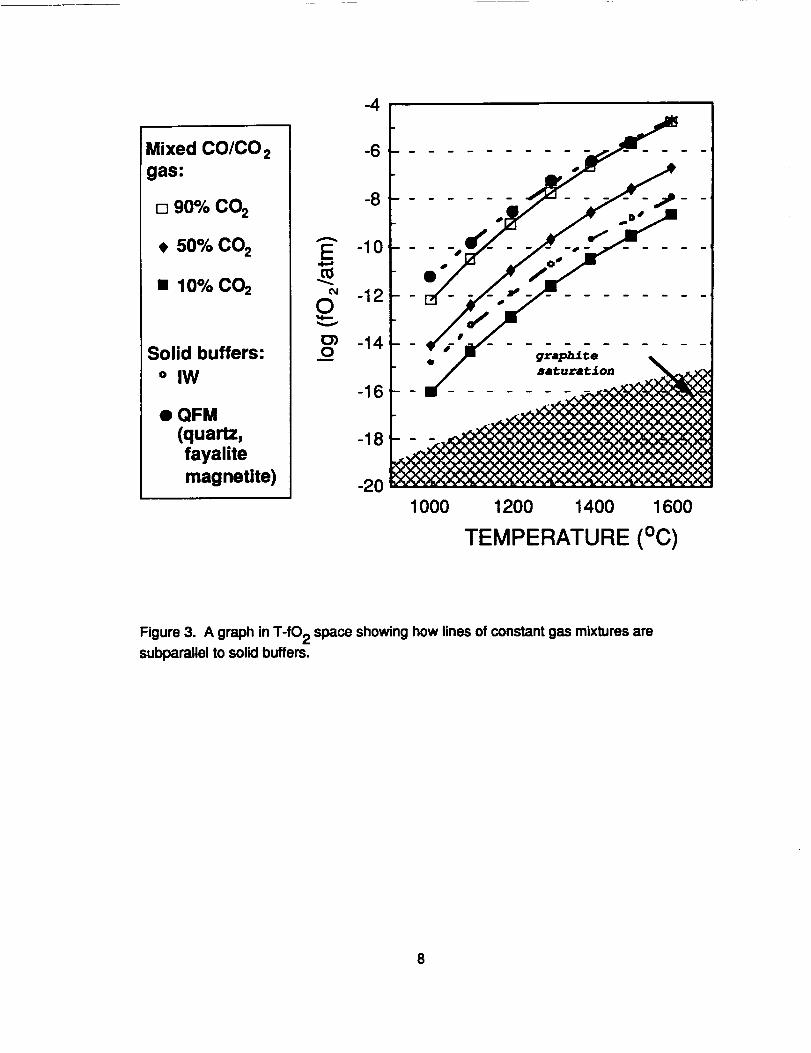
3 A graphinT-fO2spaceshowinghowlinesof constantgasmixturesaresubparallelto solidbuffers...................................................................
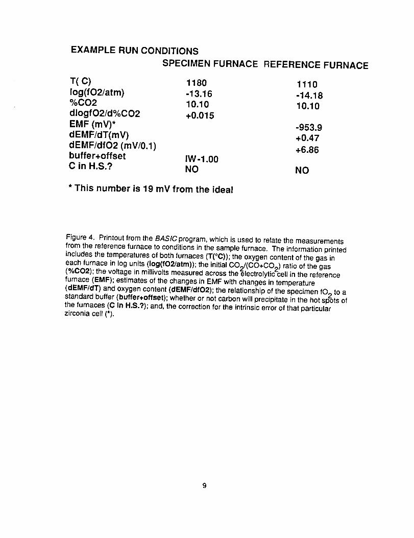
4 PrintoutfromtheBASICprogramthatis usedto relatethemeasurementsfromthereferencefurnaceto conditionsinthe
samplefurnace.........................................................................................................
iv

TECHNICAL UPDATE: JSC System Using a Solid Electrolytic Cell in a RemoteLocation to Measure Oxygen Fugaclties in CO/CO2Controlled-Atmosphere Furnaces
SUMMARY
The CO/CO 2 controlled-atmosphere furnaces in the Johnson Space CenterExperimental Petrology Laboratory have been modified so that only one solid electrolytezirconia cell 1,2 is needed for all the furnaces running under standard operatingconditions and requiring standard tolerances for deviations in oxygen fugacity. This
technique relies on measuring the oxygen fugacity (fO2) in each experimental furnaceusing a zirconia cell in a designated reference furnace. A manifold system diverts theexhaust gas from the experimental furnace containing the sample through the referencefurnace. Then, (1) the temperature and fO2 of the reference furnace are used tocalculate the composition of the exhaust gases; (2) given the temperature of the samplefurnace and the composition of the exhaust gas, the fO2 of the sample furnace isobtained from the Deines et al. (1974) tables. 3 This cumbersome procedure has been
computerized to save time and to give added flexibility to the scientist using the system.
Using a remote system for measuring fO 2 saves money by reducing the need for azirconia cell in each furnace, as well as extending the life of the cells in use. It alsowidens the range of temperatures and fO2's within which the scientist can run samples.There are, however, additional errors incurred while measuring the gases outside thesample furnace. Calibration procedures can be used to show the size of the additionalerror for a given furnace configuration and set of experimental conditions.
INTRODUCTION
Williams and Mullins' (1981) NASA Technical Memorandum 58234 describes the
basic system used at JSC for performing experiments and materials synthesis undercontrolled oxygen fugacities. 2 The system controls the partial pressure of oxygen bypassing a gas comprised of a specific mixture of CO and CO2 gases over the sampleslowly enough that they react to produce predictable, equilibrium amounts of CO, CO2,and 02. Using this method, very small concentrations of 02 can be controlled veryprecisely. For example, oxygen partial pressures of 10 "10 atm (+10 "0"2 atm) 02 are
obtained routinely.
There are, however, several limitations to the basic system described by Williams
and Mullins (1981). That system requires that an electrolytic cell be placed within eachof the furnaces, even though the cells are both fragile and expensive. Moreover, thecells are easily contaminated, and they are limited in the range of temperatures andoxygen fugacities at which they will function. So, even as Williams and Mullins (1981)was being published, new modifications were being implemented to make the systemsless expensive to maintain, more flexible, and easier to operate.
NEWMODIFICATIONS
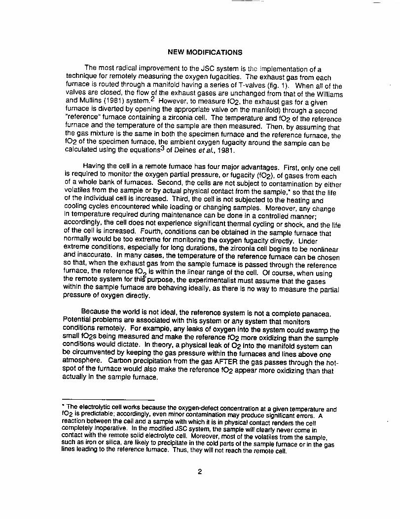
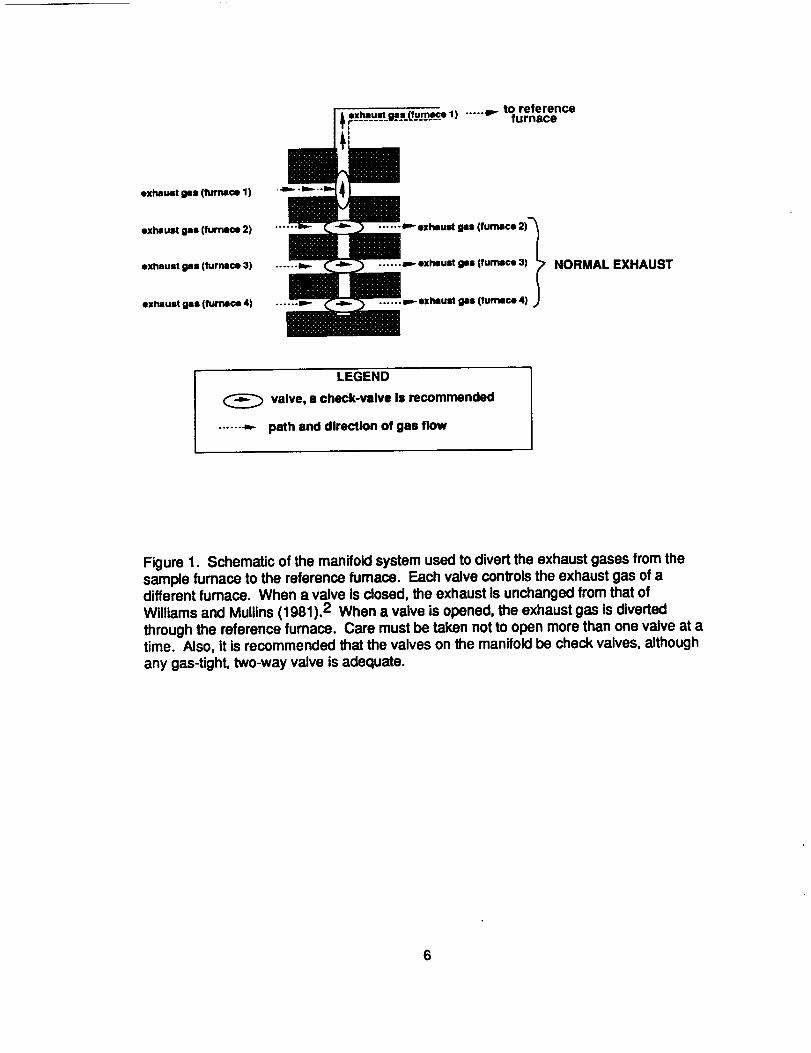
The most radical improvement to the JSC system is the implementation of atechnique for remotely measuring the oxygen fugacities. The exhaust gas from eachfurnace is routed through a manifold having a series of T-valves (fig. 1). When all of thevalves are closed, the flow of the exhaust gases are unchanged from that of the Williamsand Mullins (1981) system. 2 However, to measure fO2, the exhaust gas for a givenfurnace is diverted by opening the appropriate valve on the manifold) through a second"reference" furnace containing a zirconia cell. The temperature and fO2 of the referencefurnace and the temperature of the sample are then measured. Then, by assuming thatthe gas mixture is the same in both the specimen furnace and the reference furnace, thefO2 of the specimen furnace, the ambient oxygen fugacity around the sample can becalculated using the equations 3 of Deines etaL, 1981.
Having the cell in a remote furnace has four major advantages. First, only one cellis required to monitor the oxygen partial pressure, or fugacity (fO2), of gases from eachof a whole bank of furnaces. Second, the cells are not subject to contamination by eithervolatiles from the sample or by actual physical contact from the sample,* so that the lifeof the individual cell is increased. Third, the cell is not subjected to the heating andcooling cycles encountered while loading or changing samples. Moreover, any changein temperature required during maintenance can be done in a controlled manner;accordingly, the cell does not experience significant thermal cycling or shock, and the lifeof the cell is increased. Fourth, conditions can be obtained in the sample furnace thatnormally would be too extreme for monitoring the oxygen fugacity directly. Underextreme conditions, especially for long durations, the zirconia cell begins to be nonlinearand inaccurate. In many cases, the temperature of the reference furnace can be chosenso that, when the exhaust gas from the sample furnace is passed through the referencefurnace, the reference fO 2 is within the linear range of the cell. Of course, when usingthe remote system for this purpose, the experimentalist must assume that the gaseswithin the sample furnace are behaving ideally, as there is no way to measure the partialpressure of oxygen directly.
Because the world is not ideal, the reference system is not a complete panacea.Potential problems are associated with this system or any system that monitors
conditions remotely. For example, any leaks of oxygen into the system could swamp thesmall fO2s being measured and make the reference fO2 more oxidizing than the sampleconditions would dictate. In theory, a physical leak of 02 into the manifold system canbe circumvented by keeping the gas pressure within the furnaces and lines above oneatmosphere. Carbon precipitation from the gas AFTER the gas passes through the hot-spot of the furnace would also make the reference fO2 appear more oxidizing than thatactually in the sample furnace.
* The electrolytic cell works because the oxygen-defect concentration at a given temperature andfO2 is predictable; accordingly, even minorcontamination may produce significanterrors. Areaction between the cell and a sample with which it is in physical contact renders the cellcompletely inoperative. In the modified JSC system, the sample will clearly never come incontact with the remote solid electrolytecell. Moreover, most of the volatiles from the sample,such as iron or silica, are likely to precipitate inthe cold parts of the sample furnace or in the gaslines leading to the reference furnace. Thus, they will not reach the remote cell.
2

Severalsets of experiments have been run to quantify how large an error isincurred by sampling the gases remotely. In these experiments, the ambient fO2's in thespecimen and reference furnaces were measured simultaneously over a variety ofconditions.
The first set of these "calibration" experiments was done by R. Williams, O.Mullins, and a then summer intern student, A. Roshko, in 1981-1982 as a part of theinitial implementation of the system. Other investigators have since performed similarexperiments for their particular furnaces and conditions. In 1990, L. Le performedextensive calibrations over a wide range of fO2's for a variety of furnace configurations.This was followed in 1992 by a recalibration of L. Le's most successful furnaceconfigurations using the smaller, faster-responding Ceramic Oxide Fabricators sensors(Australian Patents #466251 and #513552).
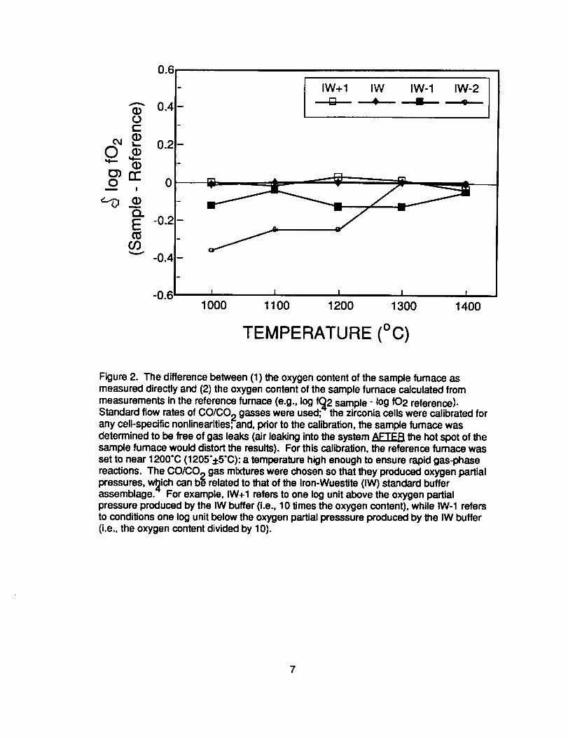
Figure 2 gives the results from one of the latest furnace calibrations. It illustratesan important point concerning the accuracy of the reference system. For the moreoxidizing CO/CO2 gas mixtures, the reference system is quite accurate over a widerange of temperaturesmthe oxygen partial pressures calculated for the sample fumaceare within xl0:l: 0.2 atmospheres of the actual oxygen content. Although not illustratedhere, loss of accuracy can occur when the sample furnace is at a lower temperature.This loss of accuracy is explained if the reaction between the CO and CO2 gas in thesample furnace has not gone to completion. As such, this error can be a function of flowrate. There is also a loss of accuracy for the more reducing CO/CO2 gas mixtures. Inthese extreme cases, this loss of accuracy is explained if the exhaust gases are unstablein the temperature gradients of either the sample furnace or the reference furnace, orboth. The instability could allow carbon to precipitate after the gas has passed thesample and entered the cooler regions of the furnace or exhaust line, causingmeasurement in the reference furnace to indicate that the sample furnace is significantlymore oxidizing than it actually is. In fact, we routinely observe such carbon precipitatesunder certain operating conditions.
In general, it has been found that the deviation in f02 between the referencefurnace and the sample furnace varies with parameters such as furnace configuration,gas flow rates, and run conditions. However, these deviations are consideredacceptably small by the majority of scientists using the system. The restrictions foraccurate use of the remote system for all of the controlled-atmosphere furnaces now inuse at JSC are
(a) redox conditions well above the graphite saturation surface,(b) temperatures high enough for the initial gas mixture to react to completion, and(c) flow rates within the recommended range (cf., ref. 4).
Experimental conditions characterized by C0/C02 gas mixtures near the graphitesaturation surface, low temperatures, or unusual gas flow rates can be attained;however, the scientist must be aware of the potential sources of error.
3
COMPUTERSOFTWARE
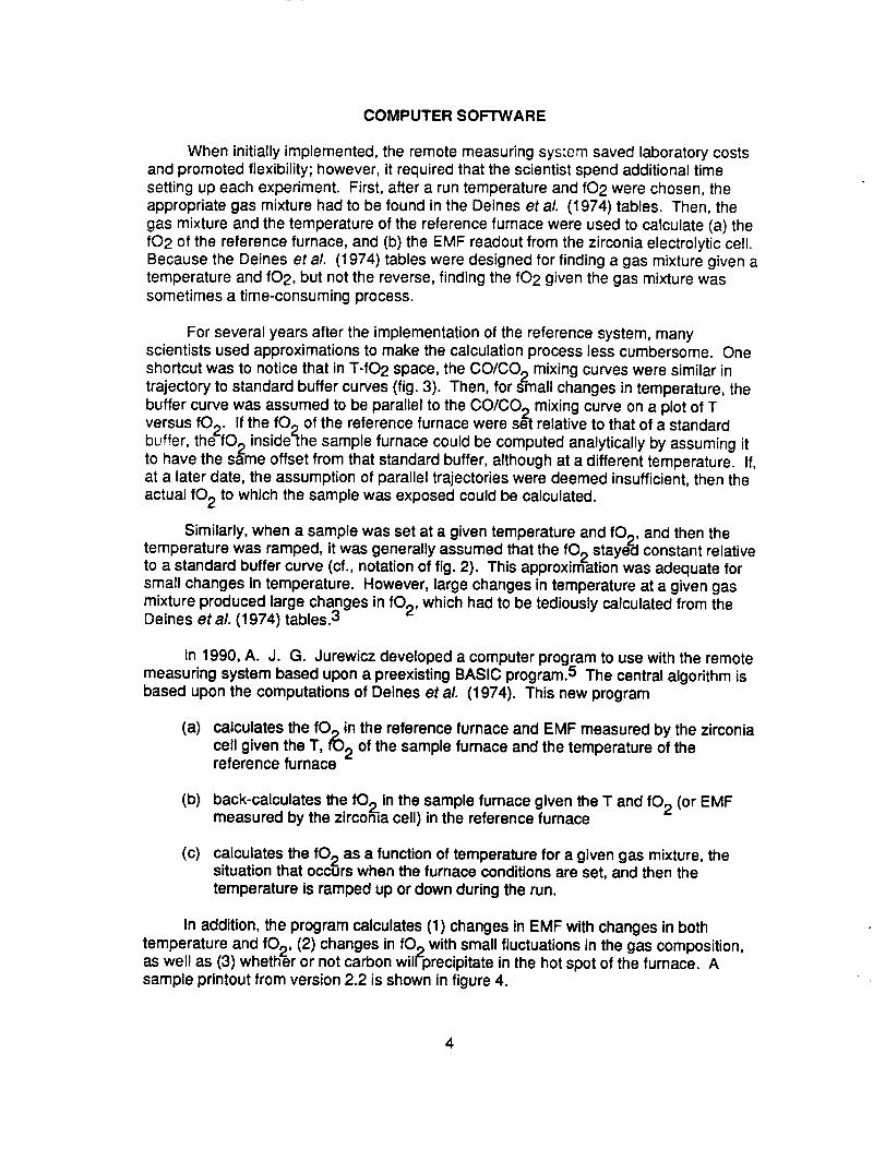
When initially implemented, the remote measuring system saved laboratory costsand promoted flexibility; however, it required that the scientist spend additional timesetting up each experiment. First, after a run temperature and fO2 were chosen, theappropriate gas mixture had to be found in the Deines et aL (1974) tables. Then, thegas mixture and the temperature of the reference furnace were used to calculate (a) thefO2 of the reference furnace, and (b) the EMF readout from the zirconia electrolytic cell.Because the Deines et al. (1974) tables were designed for finding a gas mixture given atemperature and fO2, but not the reverse, finding the fO2 given the gas mixture wassometimes a time-consuming process.
For several years after the implementation of the reference system, manyscientists used approximations to make the calculation process less cumbersome. One
shortcut was to notice that in T-fO2 space, the CO/CO 2 mixing curves were similar intrajectory to standard buffer curves (fig. 3). Then, for small changes in temperature, the
buffer curve was assumed to be parallel to the CO/CO 2 mixing curve on a plot of Tversus fOp. If the fOp of the reference furnace were set relative to that of a standard
buffer, the-fO 2 inside-the sample furnace could be computed analytically by assuming itto have the same offset from that standard buffer, although at a different temperature. If,at a later date, the assumption of parallel trajectories were deemed insufficient, then the
actual fO 2 to which the sample was exposed could be calculated.
Similarly, when a sample was set at a given temperature and fO 2, and then thetemperature was ramped, it was generally assumed that the fO 2 staye_l constant relativeto a standard buffer curve (cf., notation of fig. 2). This approximation was adequate forsmall changes in temperature. However, large changes in temperature at a given gas
mixture produced large changes in fO 2, which had to be tediously calculated from theDeines et aL (1974)tables. 3
In 1990, A. J. G. Jurewicz developed a computer program to use with the remotemeasuring system based upon a preexisting BASIC program.5 The central algorithm isbased upon the computations of Deines et aL (1974). This new program
(a) calculates the fOpin the reference furnace and EMF measured by the zirconia
cell given the T, fO 2 of the sample furnace and the temperature of thereference furnace
(b) back-calculates the fO 2 in the sample furnace given the T and fO 2 (or EMFmeasured by the zirconia cell) in the reference furnace
(c) calculates the fO 2 as a function of temperature for a given gas mixture, thesituation that occurs when the furnace conditions are set, and then thetemperature is ramped up or down during the run.
In addition, the program calculates (1) changes in EMF with changes in bothtemperature and fop, (2) changes in fOp with small fluctuations in the gas composition,as well as (3) whether or not carbon will-precipitate in the hot spot of the furnace. Asample printout from version 2.2 is shown in figure 4.
CONCLUDING REMARKS
Both the network of JSC controlled-atmosphere furnaces and the applicablecomputer software constitute a dynamic system. Physical modifications that mayincrease the reliability and the ease of using the furnaces are being tested continuously.Similarly, the computer program has been modified several times as needs arise, and itwill continue to grow and provide more flexibility and efficiency for the scientist.
REFERENCES
1. Sato, Motoaki: Electrochemical Measurements and Control of Oxygen Fugacity andOther Gaseous Fugacities with Solid Electrolyte Sensors. Research Techniques forHigh Pressure and High Temperature, Gene C. Ulmer, ed., Springer-Verlag (New York),1971, pp. 43-49.
2. Williams, R. J. and O. Mullins: JSC Systems Using Solid Ceramic OxygenElectrolyte Cells to Measure Oxygen Fugacities in Gas-Mixing Systems. NASATM-58234, 1981.
3. Deines, P.; Nafziger, R. H.; Ulmer, G. C.; and E. Woermann: Temperature-oxygenfugacity tables for selected gas mixtures in the system C-H-O at one atmosphere totalpressure. Earth and Miner. Sci. Exper. Sta., Bull., The Penn. State Univ. College ofEarth and Miner. Sci., N 88 129 pp., 1974.
4. Darkin, L. S.; and R. W. Gurry: The system iron-oxygen. I. The wustite field andrelated equilibria. J. Amer. Chem. Soc. V86, 1945, pp. 1398-1412.
5. Jurewicz, A. G. J.: Appendix 2: Software Used to Calculate Run Conditions for theDeltech Controlled-Atmosphere Furnace in Effect of Temperature, Pressure, OxygenFugacity and Composition on Calcium Partitioning, Calcium-Magnesium Distribution andthe Kinetics of Cation Exchange Between Olivines and Basaltic Melts. Thesis, GeologyDepartment, Rensselaer Polytechnic Inst. (Troy, NY, 12180), 1986, pp. 206-213
5
I_ gas (.|uml¢s 1) ..... p,- tO referenceexhaust furnaceol ................
exhaust gas (furnace 1)
exhaust gas (furnace 2)
exhaust gas (furnace 3)
exhaust gas (furnace 4)
NORMAL EXHAUST
LEGEND
valve, a check-valve is recommended
...... _ path and direction of gas flow
Figure 1. Schematic of the manifold system used to divert the exhaust gases from thesample furnace to the reference furnace. Each valve controls the exhaust gas of adifferent fumace. When a valve is closed, the exhaust is unchanged from that of
Williams and Mullins (1981).2 When a valve is opened, the exhaust gas is divertedthrough the reference furnace. Care must be taken not to open more than one valve at atime. Also, it is recommended that the valves on the manifold be check valves, although
any gas-tight, two-way valve is adequate.
0.6
- IW+l IW IW-1 IW-2
0.4- [] _ - -"
o.2-
o!
_ -0.4 -
_o61- , , , , ,1000 1100 1200 1300 1400
TEMPERATURE (Oc)
Figure 2. The difference between (1) the oxygen content of the sample fumace asmeasured directly and (2) the oxygen content of the sample furnace calculated from
measurements in the reference furnace (e.g., log f_2 sample - log fO2 reference).Standard flow rates of CO/CO 2 gasses were used;-" the zirconia cells were calibrated forany cell-specific nonlinearities; and, prior to the calibration, the sample furnace wasdetermined to be free of gas leaks (air leaking into the system AFTER the hot spot of thesample furnace would distort the results). For this calibration, the reference furnace wasset to near 1200"C (1205"+5"C): a temperature high enough to ensure rapid gas-phase
reactions. The CO/CO 2 gas mixtures were chosen so that they produced oxygen partialpressures, w_ich can be related to that of the Iron-Wuestite (IW) standard bufferassemblage.-" For example, IW+I refers to one log unit above the oxygen partialpressure produced by the IW buffer (i.e., 10 times the oxygen content), while IW-1 refersto conditions one log unit below the oxygen partial presssure produced by the IW buffer(i.e., the oxygen content divided by 10).
7
-4
Mixed CO/CO 2 -6
gas:
[] 90% CO2 -8 .....
• lOO/oC_
/_ 1 4
#
Solid buffers: _' - _'' r. - _-. ......m / • _ g =p_ t: %, ,
• QFM
(quartz, -18fayalite
magnetite) -20
1000 1200 1400 1600
TEMPERATURE (°C)
Figure 3. A graph in T-fO 2 space showing how lines of constant gas mixtures aresubparallel to solid buffers.
8
EXAMPLE RUN CONDITIONS
SPECIMEN FURNACE
T(C) 1180
log (fO2/at m) -13.16%CO2 10.10dlogfO2/d%CO2 +0.015EMF (mV)*dEMF/dT(mV)dEMF/dfO2 (mV/0.1)
buffer+offset IW-1.00C in H.S.? NO
* This number is 19 mV from the ideal
REFERENCE FURNACE
1110
-14.1810.10
-953.9+0.47
+6.86
NO
Figure 4. Printout from the BASIC program, which is used to relate the measurements
from the reference furnace to conditions in the sample furnace. The information printedincludes the temperatures of both furnaces (T(°C)); the oxygen content of the gas in
each furnace in log units (Iog(fO2/atm)); the initial CO_(CO+CO ) ratio of the gas(%CO2); the voltage in millivolts measured across the ectrolytic2cell in the referencefurnace (EMF); estimates of the changes in EMF with changes in temperature
(dEMF/dT) and oxygen content (dEMF/dfO2); the relationship of the specimen fO 2 to astandard buffer (buffer+offset); whether or not carbon will precipitate in the hot spots ofthe furnaces (C In H.S.?); and, the correction for the intrinsic error of that particularzirconia cell (*).
9


APPENDIX
SoftwareUsedalongwiththeReferenceSystemof DeterminingFurnaceConditions.
Thissoftwareactuallyconsistsof threeseparateGWBASIC programs. The programsare: GAS.BAS, used for selecting gas mixtures to acheive specific oxygen fugacitiesgiven ideal sample furnace temperatures; GASREV2.BAS, used for calculating the trueoxygen fugacity in the sample furnace, given the sample temperature and the measuredconditions in the reference furnace; and RAMP.BAS, used for seeing how conditionschange in the sample furnace at a given gas mix when the temperature is ramped. Allthree applications have been linked using the CHAIN function, and are organized by amenu program (MENU.BAS), used for selecting applications. A fourth application program,CALIB.BAS, used for calculating the ideal EMF of a zirconia cell given a chemical analysisof a calibration gas and the measured furnace temperature, is still in progress. Thesoftware is based upon the BASIC program by A. Jurewicz (1986).
A-1

Listof Variables.
A.BranchingandStringVariablesA$=generalbranchvariable.B$= YESif carbonwill precipitatein thehotspotof thefurnaceand NOotherwiseBUFFERS= the labelof thebuffer(= NONEif Z$=N)CHANGE%= branchvariablein menu.CHOICE%= branchvariablein menu.C$= generalbranchvariable.DECIDES= to continueorexitif carbonprecipitation.FURNACES= sampleorreferenceICOUNTER= for indicatingsampleor referenceJ, J1= countingvariablesforprint-outin rampingprogram.LABELS--titleforcalculation&/orprint-out.P$= branch,askingprogramto endloop.Q$ = branchvariable.ROUND%= for checkingif printerto use(Laseror Epson)hasbeendefined.STEPFO2= counterfor iterativelycalculatingoxygenfugacity,stepwise.STEPT%= temperaturestepsoverwhichto calculateoxygenfugacityat a
constantgasmixture.V$= checksfor INKEYto endpause.Y = numberof loopstheprogramhasrun (Y>0meansheadinghasalreadybeen
printed).X$,XX$= simplebranches.Z = counterfor H=+1or -1 (seeQ(Z)).Z$, Y = fO2 correspondsto a buffer;N= fO2 doesnotcorrespondto a buffer.
Constants.R= empericalconstantinequationsof equilibriumequationsof Deinesetal (1974).
NumericVariables.A = functionof K1and LOGFO2as listed.AA= newAfor shiftintemperature(calculatingDELEMFDELT).CORREMF= thesystematicoffsetoftheEMFof thereferencefurnacemeasured
duringcalibration.DELEMFDELFO2= the change in ideal EMF with a small change in furnace fO2.DELEMFDELT = the change of EMF with small changes in temperature.EMF(T,K) = EMF at temperature T (celcius) and oxygen fugacity K (log units).FCO = the partial pressure of carbon monixide.FCO2 = the partial pressure of carbon dioxide.FO2OFFSET -- deviation of oxygen fugacity from that of a standard, reference
buffer in sample furnace.FO2OFFSET2 -- deviation of oxygen fugacity from that of a standard, reference
buffer in reference furnace.GG = new Gibbs free energy for calculating DELEMFDELT.G1 = Gibbs free energy for the reaction, CO+O 2 to CO 2 from Deines et al (1974).G2 ---Gibbs free energy for the reaction, C+O2 to CO from Deines et al (1974).H = incremental change in temperature (DELEMFDELT).IDEALEMF = EMF calculated from the Nernst Equation.K1 = equilibrium constant for the reaction CO+O2 to CO2 from Deines et al (1974).K2 = equilibrium constant for the reaction, C+O2 to CO from Deines et al (1974).KK = variable equilibrium constant (for calculating DELEMFDELT).LOGFO2 = the natural logarithm of the oxygen fugacity of interest (atmospheres).MIXRATIO = %CO2 in gas mix for both furnaces.
A-2
DELRATIO= differenceingasmixbetweenwanted(MIXRATIO)andcalculatedforcalculatingoxygenfugacityof referencefurnace
NEWFO2= LOGFO2afterchangingtemperature.Q(Z)= equilibriumconstantsusedfor checkingstabilityof oxygenfugacitywith
temperatureandgasmix.REALEMF= EMFincludingsystematicoffset.REFFO2= oxygenfugacityof referencefurnace.RM(X,Y)= empiricalvariableusingequilibriumconstantX andoxygenfugacityY,
fromDeineset al (1974).SPECFO2= "specific"oxygenfugacitywantedin thesamplefurnaceduringan
experiment;thespecimenfO2.TC=samplefurnacetemperature;initialtemperatureduringramp.TREF= referencefurnacetemperature.TFINAL=finaltemperatureduringramp.VOLCO2= the gasmixtureinvolume%CO2.W = TC+Hforcalculatingstabilityofoxygenfugacitywithtemperatureandgasmix.
A-3
MENU.BAS
Thissub-programsegmentlinksallof thesub-programstogetherusingtheCHAINcommand.Essentially,it actslikea menuforselectingapplications(theothersub-programs).
SelectseitherEpsonprinterorLaserprinter(autoformfeed).Seeline204.1 ROUND%=-1:PRINTER$="EPSON"
InitialTitleforProgram
2 DIMREFFO2(100),FO2OFFSET2(100)5 DEFDBLG,A,K10 COLOR15,14,14:CLS20PRINT:PRINT:PRINT:PRINT30 PRINT" CO/CO2GASMIXINGUTILITYPROGRAM"32PRINT" version3.0":PRINT:PRINT:PRINT34 PRINT" SeeA.J.GJurewicz,if youhaveanyquestions"40PRINT:PRINT:PRINT41 COLOR14,15,1542 PRINT"Pressanykeyto continue..."50V$=INKEY$60 IF (LEN(V$)=0)GOTO50
ProgramMenu
70 COLOR15,9,9:CLS:PRINT:PRINT:PRINT:PRINT75 ROUND%=ROUND%+I80 PRINT"Doyouwant to:"90PRINT:PRINT°' 1.Takeknownsampletemperatureandoxygenfugacities"100PRINT" anddeterminethe%CO2ofthegas,andthe"102PRINT °' fO2, & EMF of reference furnace"110 PRINT:PRINT120 PRINT" 2. Take EMF (or setpoint) and T of reference furnace and"130 PRINT" determine fO2 of the sample"140 PRINT:PRINT150 PRINT" 3. Determine the range of fO2's experienced by a sample"160 PRINT" with a fixed gas mixture, but where the temperature was"170 PRINT" ramped"180 PRINT:PRINT:PRINT" 4. Exit program"185 COLOR 1,15,15190 PRINT:PRINT:PRINT "Enter choice of 1,2, 3, or 4. ";:INPUT "",CHOICE%200 IF (CHOICE%<1) OR (CHOICE%>4) GOTO 190201 IF (CHOICE%=4) GOTO 211202 IF ROUND%>0 GOTO 210
Selects either Epson printer or Laser printer. The only difference for this program is that theLaser printer requires an automatic form feed after printing.
204 COLOR 14,15,15:PRINT:PRINT:PRINT "Do you have a laser printer (Y/N)?";:206 Q$=INPUT$(1):IF (Q$="y") OR (Q$="Y") GOTO 209207 IF (Q$="N") OR (Q$="n") GOTO 210208 PRINT "HUH?":GOTO 204209 PRINTER$="LASER"
A-4
Branchtoothersub-programs,or Exit,asselectedonmenu.
210 COLOR31,1,1:CLS:PRINT:PRINT:PRINT:PRINT"LOADINGNEXTSEGMENT"211 ON CHOICE%GOTO220,230,240,250220230240250252260270280290300305310
CHAIN"GAS.BAS",I0,ALLCHAIN"GASREV2",I0,ALLCHAIN"RAMP",10,ALLCOLOR17,15,15PRINT:PRINT:PRINT"Areyousurethatyouwantto exit (Y/N)?";:Q$=INPUT$(1):IF(Q$="y")OR (Q$="Y")GOTO290IF (Q$="N")OR (Q$="n")GOTO70PRINT"HUH?":GOTO240PRINT"O.K.":COLOR15,0,0:CLSPRINT:PRINT:PRINT:PRINTPRINT"Atthe OKprompt,typeSYSTEM"PRINT"Toreturntotheoperatingsystem":PRINT:PRINT:END
A-5
GAS.BASThissub-programtakesthesampletemperatureandoxygenfugacitywhichtheexperimentalistdesires,andcalculateswhatthegasmixtureshouldbe.Then,giventhetemperatureofthereferencefurnace,calculatestheoxygenfugacityofthereferencefurnaceandtheEMFregisteredby thezirconiacell.
SetsUser-definedfunctionsaswellasmainmenu.
10REM20 REMTHISVERSIONINCLUDESCHANGINGREFERENCEGASTOOXYGEN30 DEFFNEMF(T,K)= .0496055*(T+273)*(K+0)40 REMDEFDBLG,K,A50 DEFFN RM(X,Y)=(X-3*X*(10^Y)-2"((10^Y)̂ (3/2)))/(2"X*(10^Y)+(10̂Y)+((10̂ Y)̂ (3/2))+SQR(10^Y))52 COLOR15,1,1:CLS60PRINT:PRINT62 PRINT" PROGRAMTOCALCULATEPARAMETERSTO BE USEDWITH"70 PRINT" NASACO/CO2GAS-MIXINGFURNACES"72PRINT73PRINT" REMINDER.... "80PRINT" FOREXTREMERANGES(OTHERTHAN1000C<T<1400,-6<logfO2<-16)"90 PRINT" THEZlRCONIACELLMAYBECOMENON-IDEAL"100COLOR6,15,15127PRINT:PRINT"Doyouwishto continue,or returnto themainmenu(C/R)?"128Q$=INPUT$(1)129 IF (Q$="c")OR (Q$="C")GOTO150130 IF (Q$="r")OR (Q$="R")GOTO140135 PRINT:PRINT"HUH?":PRINT:GOTO127140CHAIN"MENU.BAS",70,ALL
Selectingandchangingvariables.
150Y=0:R=1.98726E-03200 REMVARIABLESUSEDARE:TC,TREF,FO2OFFSET2,BUFFER$,REFFO2,REALEMF,CORREMF202 REMMOREVARIABLESUSEDARE:IDEALEMF205 PRINT:PRINT:PRINT210 TC=1400:TREF=1065:FO2OFFSET2=-I:BUFFER$="IW":SPECFO2=-10.69719215 CORREMF=26:BUFFER$="IW"2202252302502552602702652702803OO
COLOR15,3,3:CLS:PRINT:PRINT:PRINT"Thecurrent conditions are:"B$(1 )="NO":B$(2)="NO":DECIDE$="YES"PRINT:PRINT" 1. Sample temperature is ";TC;" degrees C"PRINT" 2. Sample oxygen fugacity is ";SPECFO2;" log (/atm)"IF (FO2OFFSET2--0) GOTO 265PRINT" --- which is ";BUFFERS;" offset ";FO2OFFSET2;" log units":GOTO
PRINT" --- which is ";BUFFERSPRINT" 3. Reference temperature is ";TREF;" degrees C"PRINT" 4. The correction to the zirconia cell is ";CORREMF;" mV"PRINT" and 5. The reference buffer is ";BUFFERS
A-6
320 PRINT:PRINT:PRINT380COLOR15,9,9:PRINT"Enterthenumberyouwishto change(1- 5, 6 tocontinue;7 toexit).";:390 INPUT.... ,CHANGE%400 IF (CHANGE%>0)AND(CHANGE%<8)GOTO420410 COLOR31,9,9:PRINT"Pleaseentera number,1 - 7.";:COLOR15,9,9:GOTO390420 CLS:ONCHANGE%GOTO430,580,440,450,487,1000,140
Changingsampletemperatureat constantfO2.
430 INPUT"EnterthenewsampletemperatureindegreesC";TC431 IF (BUFFER$="IW")GOTO850432 IF (BUFFER$="WM")GOTO851433 IF (BUFFER$="MH")GOTO852434 IF (BUFFER$="QFM")GOTO853435 IF(BUFFER$="NNO")GOTO854436 PRINT"ERRORIN PROGRAM/NOBUFFER":STOP
Changingreferencefurnacetemperature.
440 INPUT "Enter the new reference temperature in degrees C";TREF:CLS:GOTO220
Changing the deviation of zirconia cell from the ideal (systematic offset determined bycalibration at reference temperature).
450 INPUT "Enter the new correction to the zirconia celI";CORREMF:CLS:GOTO220
Changing the oxygen fugacity of the sample furnace, as well as the reference buffer(see also 580).
4604704804854874905OO51052053053554055056O570571572573574575
CLS :PR INT:PR INT:PR INT
PRINT "The sample fO2 data will be given as relative to a buffer, as well"PRINT "as in Iog(fO2/atm) units. Your choice of 'reference buffers' are:"GOTO 490CLS:PRINT:PRINT:PRINT:PRINT "Your choice of reference buffers are:"PRINT:PRINT" 1. IW"PRINT" 2. WM"PRINT" 3. MH"PRINT" 4. QFM"PRINT" 5. NNO"
PRINT:PRINT "(Your current choice is )";BUFFERSPRINT:PRINT "Enter the number of your selection."INPUT" ",CHANGE%IF (CHANGE%<1) OR (CHANGE%>5) GOTO 460ON CHANGE% GOTO 571,572,573,574,575BUFFER$="IW":GOTO 850BUFFER$="WM":GOTO 851BUFFER$="MH":GOTO 852BUFFER$="QFM":GOTO 853BUFFER$="NNO":GOTO 854
A-7

580 CLS590 PRINT:PRINT:PRINT600 PRINT"ThesamplefurnacefO2canbeexpressedas anyof threeways:"610 PRINT:PRINT" 1.asa standardbuffer"620PRINT" 2. asoffsetfromastandardbuffer"630 PRINT" 3. asa specificfO2 (independentof anybuffer)"650 PRINT:PRINT"Howwouldyouliketo expressyournewfO2"660PRINT" (Enter1-3,or4 for unchanged)."670 INPUT....,CHANGE%680 IF (CHANGE%<1)OR (CHANGE%>4)GOTO590690 ON CHANGE%GOTO700,700,820,692692 CLS:GOTO220700PRINT:PRINT"Yourchoicesof standardreferencebuffersare:":PRINT701 PRINT" 1. IW"702 PRINT" 2.WM"703 PRINT"3. MH"704 PRINT"4. QFM"705 PRINT" 5. NNO"706 PRINT" 6. noneabove.Returnto previousmenu."710 PRINT:PRINT"Enterthenumberofyourselection.";:720 INPUT.... ,CHOICE%730 IF (CHOICE%<1)OR (CHOICE%>6)GOTO710740 FO2OFFSET2=0:IF(CHANGE%=1)GOTO760750 INPUT"Entertheoffsetfromthebuffer,in log(fO2/atm)units.",FO2OFFSET2760 ON CHOICE%GOTO770,780,790,800,810,580770 SPECFO2 = 6.57 - 27215/(TC +273)+FO2OFFSET2:BU FFER$="IW":CLS:GOTO 220780 SPECFO2 = 13.12 - 32730/(TC +273)+FO2OFFSET2:BU FFER$="WM":CLS:GOTO 220790 SPECFO2 = 13.966 - 24634/(TC +273)+FO2OFFSET2:BU FFER$="MH":CLS:GOTO 220800 SPECFO2 = 9! - 25738/(TC +273)+FO2OFFSET2:BU FFER$="QFM":CLS:GOTO 220810 SPECFO2 = 9.359999 - 24930/(TC +273)+FO2OFFSET2:BUFFER$="N NO":CLS:GOTO 220820 CLS:PRINT:PRINT "The current Iog(fO2) is ";SPECFO2830 PRINT:PRINT "What is the log of the new f02 that you want? ";:840 INPUT SPECFO2:GOTO 431850 FO2OFFSET2=SPECFO2-(6.57 - 27215/(TO + 273)):CLS:GOTO 220851 FO2OFFSET2=SPECFO2-(13.12 - 32730/(TC + 273)):CLS:GOTO 220852 FO2OFFSET2=SPECFO2-(13.966 - 24634/(TC + 273)):CLS:GOTO 220853 FO2OFFSET2=SPECFO2-(91 - 25738/(TC + 273)):CLS:GOTO 220854 FO2OFFSET2=SPECFO2-(9.359999 - 24930/(TC + 273)):CLS:GOTO 220
Program branches to calculate the parameters of interest: the gas mix needed for the samplefurnace, the oxygen fugacity of the reference furnace, the EMF of the zirconia cell in thereference furnace, and the effect of small changes in the gas mixture on the oxygen fugacityin the sample furnace and the EMF of the reference furnace•
1000 COLOR 15,0,01001 REM NOW FO2 HAS BEEN INPUT1010 REM SUBROUTINE AT 1750 CALCULATES GASMIXTURES, 1830 = CSTABILITY1020 REM SUBROUTINE AT 1100 CALCULATES EMF'S
A-8
1030REMSUBROUTINEAT1380CALCULATESDELEMFDELT;1680=DEMFDFO21031REMSUBROUTINEAT 1530ITERATESREFERENCEFURNACEFO21035CLS:PRINT:PRINT:PRiNT"WORKING.... "10401O5O106010701080109011001110112011211125
LOGFO2=SPECFO2:T=TC:GOSUB1760MIXRATIO=VOLCO2:FURNACE$="SAMPLE":ICOUNTER=I:GOSUB1830IF (VOLCO2>100)GOTO1290IF (DECIDE$="NO")GOTO220GOSUB1530FURNACE$="REFERENCE":ICOUNTER=2:GOSUB1830IF (DECIDE$="NO")GOTO220GOSUB1680GOSUB1380REMCALCULATINGAPPROX.DCO2/DFO2DELFO2DELCO2=0.1/(DVOLCO2)
Printingroutinefor printingfinishedresultstothescreen.
1130PRINT:PRINT:PRINT"Entera labelforyourrunconditions:";:INPUTLABELS1140CLS1150PRINTLABELS1160PRINT:PRINT:PRINTSPC(15);"SPECIMENFURNACE";" REFERENCEFURNACE"1170PRINTUSING"\ \ #### ####";"T(C)";TC;TREF1180PRINTUSING'_ \ +##.##+##.##";"Iog(fO2/atm)";SPECFO2;REFFO21190PRINTUSING"\ \ ###.#####.##";"%CO2";MIXRATIO;(MIXRATIO-DELRATIO)1195PRINTUSING'& \+#.###";"dlogfO2/d%CO2";DELFO2DELCO21200PRINTUSING'& \ +####.#";"EMF(mV)*";REALEMF1210PRINTUSING"_ \ +##.##";"dEMF/dT(mV)";DELEMFDELT1220PRINTUSING"\ \+##.##";"dEMF/dfO2(mV/.1)";DELEMFDELFO21225IF (FO2OFFSET2=0)GOTO12401230PRINTUSING'_ \\ \ +#.##";"buffer+offset";BUFFER$;FO2OFFSET2.GOTO12601240PRINTUSING"_ \ \ \ ";"buffer";BUFFER$1260PRINTUSING"Cin H.S.? \ \ \ \";B$(1);B$(2)1270127212731274127512761277127812791280129013001301131013201330
PRINT:PRINT"* Thisnumberis offset";CORREMF;"mVfromtheideal."PRINT:PRINT°'Doyouwishto Printtheresults,Continuewiththisprogram,"PRINT" or Returnto themainmenu?(P/C/R)"P$=INPUTS(1)IF(P$="r")OR(P$="R")GOTO1360IF (P$="c")OR (P$="C")GOTO1350IF(P$="p")OR (P$="P")GOTO1279PRINT:PRINT:PRINT"Huh?":PRINT:GOTO1272GOSUB2150GOTO1300PRINT"Thegasmixis unrealistic(eg.,";VOLCO2;"%).Try again."PRINT:PRINT"Doyouwishto continuewiththisprogram,"PRINT" or returnto themainmenu?(C/R)"AS=INPUTS(1)IF (A$="r")OR (A$="R")GOTO1360IF (A$="c")OR (A$="C")GOTO1350
A-9
13401350136013651370
PRINT:PRINT:PRINT"Huh?":PRINT:GOTO1300CLS:GOTO220CLSCHAIN"MENU.BAS",70,ALLEND
Sub-routineforcalculatingthedeviationsinoxygenfugacitywithtemperature..
1380139014001410142014301440
Z=IRATIO= FCO2/(1-FCO2-10hREFFO2)AA =(1- 2*RATIO*(100/ MIXRATIO - 1))/(1 + 2"(100 / MIXRATIO - 1))PART = LOG(1 - AA)- LOG(100 / MiXRATIO - 1)FOR I= 1 TO- 1 STEP -2H=IW=T+H
1450 GG = 62.110326# - .02144446#*W + 4.720326E-07*(W h 2)+(-4.5574288#)*(10h( - 12))*(W h 3)- 7.343018200000001 #*(10h( - 15))*(W h 4)1460 KK = EXP(- GG/(R*(W + 273.18)))1470 Q(Z)= KK1480 Z = Z + 11490 NEXT I1500 NEWFO21 = LOG(10)*.5*(LOG(Q(1 ))+ PART):NEWFO22 =LOG(10)*.5*(LOG(Q(2))+ PART)1510 DELEMFDELT =(FN EMF (TREF + 1,NEWFO21) - FN EMF (TREF - 1,NEWFO22))/21520 RETURN
Given a gas mixture and a temperature, this sub-routine calculates the oxygen fugacity ofthe fumace, as well as the expected EMF of the zirconia cell.
1530 REM SUBROUTINE TO ITERATIVELY CALCULATE THE FO2 OF THEREFERENCE FURNACE1540 STEPFO2=I !:IF (TC>TREF) GOTO 15701550 IF (TC=TREF) GOTO 15701560 STEPFO2=-STEPFO21570 T=TREF1580 LOGFO2=LOGFO2-STEPFO2:GOSUB 17601590160016101620163016401650166016651670
DELRATIO=MIXRATIO-VOLCO2IF ABS(DELRATIO)<.001 GOTO 1660IF (TREF>TC) GOTO 1640IF (DELRATIO<0) GOTO 1580LOGFO2=LOGFO2+STEPFO2:STEPFO2=STEPFO2/2:GOTO 1580IF (DELRATIO>0) GOTO 1580LOGFO2=LOGFO2+STEPFO2:STEPFO2=STEPFO2/2:GOTO 1580REFFO2=LOGFO2IDEALEMF=FN EMF(TREF,REFFO2):REALEMF=IDEALEMF+CORREMFRETURN
Sub-routine calculates the EMF of the zirconia cell in the reference furnace, as well as thechange of EMF with small changes in temperature and oxygen fugacity.
1680 REM NOW THAT WE HAVE TEMPERATURE AND LOGFO2, WE NEED TOCALCULATE THE EMF'S AND DELTA-EMF'S1690 IDEALEMF = FN EMF (TREF,REFFO2)
A-10
1700 DELEMFDELFO2 =( FN EMF (TREF,(REFFO2 + .1))- FN EMF(TREF,(REFFO2 - .1 )))/21740 RETURN
Sub-routine for taking the temperature of a furnace and computing the CO/CO 2 gas mixtureneeded to obtain a specific oxygen fugacity.
1750 REM NOW WE WANT TO TAKE THE T, FO2 CONDITIONS & COMPUTETHE %CO2
1760 G1 = 62.110326# + T*(- .02144446#)+(Th2)*(4.720326)*(10h(- 7))+(Th3)*(-4.5574288#)*(10h( - 12))+(Th4)*(- 7.343018200000001 #)*(10h( - 15))1770 G2 = 94.25770200000001# + T*(7.321945)*(10h('4))-(Th2)*(10h(-7))*(3.416474)+(Th3)*(4.7858617#)*(10h( - 11))1780 K1 = EXP(- G1 /(R*(T + 273.18))): K2 = EXP(- G2 /(R*(T + 273.18)))1790 A =(K1 "(SQR(10hLOGFO2))*FN RM(K1 ,LOGFO2))/(K1 +SQR(10hLOGFO2))1800 FCO2 = 2"(1 - A)/(2 + A + 2*FN RM(K1,LOGFO2))1810 VOLCO2 = 100 /(1 + FNRM(K1 ,LOG FO2)):DVOLCO2= 100/(1 +FN RM(K1 ,(LOGFO2+. 1)))-100/(1 +FNRM(K1 ,(LOG FO2-. 1)))/21820 RETURN
Sub-routine for checking whether carbon will precipitate in the hot-spot of the furnace.
1830 IF ((10 h LOGFO2)>(K2*FCO2)) GOTO 19201840 B$(ICOUNTER)="YES": PRINT:PRINT "Carbon WILL precipitate in the";FURNACES;" using these settings."1850 PRINT "DO YOU WANT THE INFORMATION ANYWAY (Y/N)?"1860 INPUT X$18701880189018601900191019201930
IF (X$="Y") OR (X$="y") GOTO 1900IF (X$="n") OR (X$="N") GOTO 1910PRINT:PRINT: "1don't understand. Please try again.":PRINT:PRINT:GOTO
DECIDE$="YES":GOTO 1930DECIDE$="NO":GOTO 1930B$(ICOUNTER)="NO"
RETURN
Routine for printing the results to paper.
2150 LPRINT LABELS2160 LPRINT:LPRINT:LPRINT SPC(15);"SPECIMEN FURNACE ";" REFERENCEFURNACE"2170 LPRINT USING "\ \ #### ####";"T( C)";TC;TREF2180 LPRINT USING "\ \ +##.##+##.##";"Iog(fO2/atm)";SPECFO2;REFFO22190 LPRINT USING '& \ ###.#####.##";"%CO2";MIXRATIO;(MIXRATIO-DELRATIO)2195 LPRINT USING '& \+#.### ";"dlogfO2/d%CO2";DELFO2DELCO22200 LPRINT USING '& \ +####.#";"EMF(mV)*";REALEMF2210 LPRINT USING "\ \ +##.##";"dEMF/dT(mV)";DELEMFDELT2220 LPRINT USING "\ \+##.##";"dEMF/dfO2(mV/. 1)";DELEMFDELFO22225 IF (FO2OFFSET2=0) GOTO 2240
A-11

2230LPRINTUSING"\ \\ \ +#.##";"buffer+offset";BUFFER$;FO2OFFSET2:GOTO22602240LPRINTUSING"\ \ \ \ ";"buffer";BUFFER$2260LPRINTUSING"Cin H.S.? \ \ \ \";B$(1);B$(2)2270LPRINT:LPRINT"*Thisnumberis offset";CORREMF;"mVfromtheideal."2275 IF (PRINTER$="EPSON")GOTO22782276 LPRINTCHR$(12);:GOTO22802278LPRINT:LPRINT2280 CLS2290RETURN
A-12
GASREV2.BAS
Thissub-programtakesolddata,forwhich(1)thereferenceconditions(temperature,EMF)and(2)thesampletemperatureareknownandcalculateswhattheambientoxygenfugacitywas inthesamplefurnace.
SetsUser-definedfunctions,aswellasmainmenu.
1 REMVARIABLESINCLUDE:MIXRATIO,VOLCO2,G1,G2, (ALLVARIABLES2 REMFROMDEFAULTS.BAS),DVOLCO2,FCO2,R, K1,K2,A, B$(1),B$(2),OPTIONS%3 REMT, LOGFO2,DCO2DFO2REF4 REMDEFDBLG,A,K10DEFFN RM(X,Y)=(X-3*X*(10^Y)-2"((10*Y)̂ (3/2)))/(2"X*(10^Y)+(10*Y)+((10*Y)A(3/2))+SQR(10^Y))13R=1.98726"10^(-3)15COLOR15,14,14:CLS:PRlNT:PRINT:PRINT20 PRINT" PROGRAMTOTAKEDATAFROMREFERENCEFURNACE":PRINT30PRINT" ANDTOCALCULATETHECONDITIONSINTHESAMPLEFURNACE"35PRINT" FORCO/CO2GASMIXINGSYSTEMS"40PRINT:PRINT:PRINT50COLOR15,1,1:PRINT"Doyouwishto continue,or returnto themainmenu(C/R)?"60 Q$=INPUT$(1 )70 IF (Q$="c") OR (Q$="C") GOTO 11080 IF (Q$="R") OR (Q$="r") GOTO 10085 PRINT "HUH?":GOTO 50100 CHAIN "MENU.BAS",70,ALL
Sets default variables, and allows them to be changed using a menu-driven system.
110 CLS113 TC=1400:TREF--1065:FO2OFFSET=0:BU FFER$="IW":REFFO2=-13.7706:FO2OFFSET2=0114 IDEALEMF=-913.9486:CORREMF=26:BUFFER$="IW"200 REM VARIABLES USED ARE:TC,TREF, FO2OFFSET,BUFFER$,REFFO2,REALEMF,CORREMF202 REM MORE VARIABLES USED ARE: IDEALEMF205 COLOR 15,4,4:CLS:PRINT:PRINT:PRINT:REALEMF=IDEALEMF+CORREMF220 PRINT "The current conditions are:"230 PRINT:PRINT" 1. Sample temperature is ";TC;" degrees C"240 PRINT" 2. Reference temperature is ";TREF;" degrees C"25025526027026527029030O320330
PRINT" 3. Reference oxygen fugacity is ";REFFO2;" log (/atm)"
IF (FO2OFFSET=0) GOTO 265PRINT" --- which is ";BUFFERS;" offset ";FO2OFFSET;" log units":GOTO
PRINT" --- which is ";BUFFERSPRINT" --- the corrected EMF is ";IDEALEMF+CORREMF;" mV"PRINT" 4. The correction to the zirconia cell is ";CORREMF;" mV"PRINT" and 5. The reference buffer is ";BUFFERSPRINT:PRINTCOLOR 4,15,15
A-13
380 PRINT "Enter the number you wish to change (or 6 to continue; 7 to exit)";:390 INPUT .... ,CHANGE%400 IF (CHANGE%>0) AND (CHANGE%<8) G©T© 420410 COLOR 31,1,1 :PRINT "Please enter a number, 1 - 7.";:COLOR 15,1,1 :GOTO390420 ON CHANGE% GOTO 430,440,580,450,487,1000,100
Changes sample temperature at constant.
430 INPUT "Enter the new sample temperature in degrees C";TC:CLS:GOTO 205
Changes reference temperature.
440 INPUT "Enter the new reference temperature in degrees C";TREF:CLS:GOTO845
Changes systematic deviation in the zirconia cell.
450 INPUT "Enter the new correction to the zirconia celI";CORREMF:CLS:GOTO205
Changes the standard reference buffer used to describe the oxygen fugacity.
460 CLS:PRINT:PRINT:PRINT
470 PRINT "The sample fO2 data will be given as relative to a buffer, as well"480 PRINT "as in Iog(fO2/atm) units. Your choice of 'reference buffers' are:"485 GOTO 490487 CLS:PRINT:PRINT:PRINT:PRINT "Your choice of buffers are:"490 PRINT:PRINT" 1. IW"500 PRINT" 2. WM"510 PRINT" 3. MH"520 PRINT" 4. QFM"530 PRINT" 5. NNO"535 PRINT:PRINT "(Your current choice is )";BUFFERS540 PRINT:PRINT "Enter the number of your selection.";:550 INPUT" ",CHANGE%
560 IF (CHANGE%<1) OR (CHANGE%>5) GOTO 460570 ON CHANGE% GOTO 571,572,573,574,575571 BUFFER$="IW":GOTO 850572 BUFFER$="WM":GOTO 850573 BUFFER$="MH":GOTO 850574 BUFFER$="QFM":GOTO 850575 BUFFER$="NNO":GOTO 850
Changes the oxygen fugacity of the reference furnace. This section allows the oxygenfugacity to be described either as a standard buffer, as an offset from a standard buffer,or in atmospheres (log units).
58O CLS590 PRINT:PRINT:PRINT
600 PRINT "The reference furnace fO2 can be expressed as any of several ways:"610 PRINT:PRINT" 1. as a standard buffer"620 PRINT" 2. as offset from a standard buffer"
630 PRINT" 3. as a specific fO2 (independent of any buffer) "
A-14

640PRINT" 4. astheEMF(inmV)indicatedbythezirconiacell"650 PRINT:PRINT"Howwouldyou liketo expressyournewfO2"660PRINT°' Enter1-4(or5 to continue;6 t3 exit).";:670 INPUT .... ,CHANGE%680 IF (CHANGE%<1) OR (CHANGE%>6) GOTO690 ON CHANGE% GOTO 700,700,820,870,205,100
700 PRINT:PRINT "Your choices of standard reference buffers are:":PRINT701 PRINT "1. IW"702 PRINT "2. WM"703 PRINT" 3. MH"704 PRINT "4. QFM"705 PRINT " 5. NNO"706 PRINT" 6. none above. Return to previous menu."710 PRINT:PRINT "Enter the number of your selection.";:720 INPUT .... ,CHOICE%730 IF (CHOICE%<1) OR (CHOICE%>6) GOTO 710740 FO2OFFSET=0:IF (CHANGE%=1) GOTO 760750 INPUT "Enter the offset from the buffer, in log (fO2/atm) units.",FO2OFFSET760 ON CHOICE% GOTO 770,780,790,800,810,580770 REFFO2 = 6.57 - 27215/(TREF +273)+FO2OFFSET:IDEALEMF=0.0496055*(TREF+273)*REFFO2:BU FFER$="IW":CLS:GOTO 205780 REFFO2 = 13.12 - 32730/(TREF +273)+FO2OFFSET:I DEALE MF=0.0496055*(TREF+273)*REFFO2:BU FFER$="WM":CLS:GOTO 205790 REFFO2 = 13.966 - 24634/(TREF +273)+FO2OFFSET:IDEALEMF=0.0496055*(TREF+273)*REFFO2:BUFFER$="MH":CLS:GOTO 205800 REFFO2 = 9! - 25738/(TREF +273)+FO2OFFSET:IDEALEMF=0.0496055*(TREF+273)*REFFO2:BUFFER$="QFM":CLS:GOTO 205810 REFFO2 = 9.359999 - 24930/(TREF +273)+FO2OFFSET:IDEALEMF=0.0496055*(TREF+273)*REFFO2:BUFFER$="NNO":CLS:GOTO 205
820 CLS
830 PRINT:PRINT "What is the log of the f02 you want? ";:840 INPUT REFFO2845 IDEALEMF=0.0496055*(TREF+273)*REFFO2850 IF (BUFFER$="IW") GOTO 860852 IF (BUFFER$="WM") GOTO 862854 IF (BUFFER$="MH") GOTO 864856 IF (BUFFER$="QFM") GOTO 866858 IF (BUFFER$="NNO") GOTO 868859 PRINT "THERE IS A PROBLEM WITH THE PROGRAM!!!!!":STOP860 FO2OFFSET=REFFO2-(6.57 - 27215/(TREF + 273)):GOTO 205862 FO2OFFSET=REFFO2-(13.12 - 32730/(TREF + 273)):GOTO 205864 FO2OFFSET=REFFO2-(13.966 - 24634/(TREF + 273)):GOTO 205866 FO2OFFSET=REFFO2-(9! - 25738/(TREF + 273)):GOTO 205868 FO2OFFSET=REFFO2-(9.359999 - 24930/(TREF + 273)):GOTO 205
870 CLS880 PRINT:PRINT:PRINT
A-15
890PRINT"TheEMF(inmV)thatyouenterisassumedto be the"891PRINT"correctedvalue(i.e,whatyoureadon themeter)."892PRINT"Thecurrentcorrectionfactoris";CORREMF;"mV."894 PRINT"Is that O.K.(Y/N)?"900 C$-INPUT$(1)902 IF (C$="Y")OR (C$="y")GOTO920904 IF (C$="N")OR (C$="n")GOTO910906 PRINT"HUH?":GOTO870910 INPUT"Enterthecorrection,inmV(lowis +).",CORREMF920 INPUT"EntertheEMFinmV(eg.,-908)",REALEMF930 IDEALEMF=REALEMF-CORREMF940 REFFO2=IDEALEMF/(0.0496055*(TREF+273))950 GOTO850
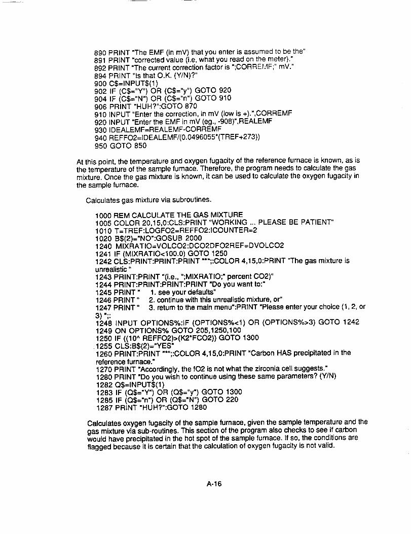
At thispoint,thetemperatureandoxygenfugacityof thereferencefurnaceis known,as isthetemperatureofthesamplefurnace.Therefore,theprogramneedstocalculatethegasmixture.Oncethegasmixtureis known,it canbeusedto calculatetheoxygenfugacityinthesamplefurnace.
Calculatesgasmixtureviasubroutines.
12441245124612473)";:124812491250
1255
1000 REM CALCULATE THE GAS MIXTURE1005 COLOR 20,15,0:CLS:PRINT "WORKING ... PLEASE BE PATIENT"1010 T=TREF:LOGFO2=REFFO2:ICOUNTER=21020 B$(2)--"NO":GOSUB 20001240 MIXRATIO=VOLCO2:DCO2DFO2REF=DVOLCO21241 IF (MIXRATIO<100.0) GOTO 12501242 CLS:PRINT:PRINT:PRINT "*";:COLOR 4,15,0:PRINT "The gas mixture isunrealistic"1243 PRINT:PRINT "(i.e., ";MIXRATIO;" percent CO2)"
PRINT:PRINT:PRINT:PRINT "Do you want to:"PRINT" 1. see your defaults"PRINT" 2. continue with this unrealistic mixture, or"PRINT" 3. return to the main menu":PRINT "Please enter your choice (1,2, or
INPUT OPTIONS%:IF (OPTIONS%<1) OR (OPTIONS%>3) GOTO 1242ON OPTIONS% GOTO 205,1250,100IF ((10 ^ REFFO2)>(K2*FCO2)) GOTO 1300CLS:B$(2)="YES"
1260 PRINT:PRINT "*";:COLOR 4,15,0:PRINT "Carbon HAS precipitated in thereference furnace."1270 PRINT "Accordingly, the fO2 is not what the zirconia cell suggests."1280 PRINT "Do you wish to continue using these same parameters? (Y/N)1282 Q$=INPUT$(1 )1283 IF (Q$="Y") OR (Q$="y") GOTO 13001285 IF (Q$="n") OR (Q$="N") GOTO 2201287 PRINT "HUH?":GOTO 1280
Calculates oxygen fugacity of the sample furnace, given the sample temperature and thegas mixture via sub-routines. This section of the program also checks to see if carbonwould have precipitated in the hot spot of the sample furnace. If so, the conditions areflagged because it is certain that the calculation of oxygen fugacity is not valid.
A-16
1300REMWE NOWHAVETC,VOLCO2=MIXRATIO,WE NEEDFO2OFSAMPLEFURNACE1310 ICOUNTER=I1320 COLOR15,1,1:B$(1)="NO":GOSUB23001330GOSUB20001340 DCO2DFO2SPEC=DVOLCO21350 IF((10̂ SPECFO2)>(K2*FCO2))GOTO13901355CLS:B$(1)="YES"1360PRINT:PRINT.....;:COLOR4,15,0:PRINT"CarbonHASprecipitatedin thespecimenfurnace."1370PRINT"Accordingly,thefO2 isnotwhatthezirconiacellsuggests."
1380PRINT"Doyouwishto continueusingthesesameparameters?(Y/N)1382Q$=INPUT$(1)1383IF (Q$="Y")OR (Q$="y")GOTO14001385IF (Q$="n")OR (Q$="N")GOTO2201387PRINT"HUH?":GOTO13801390GOSUB2800
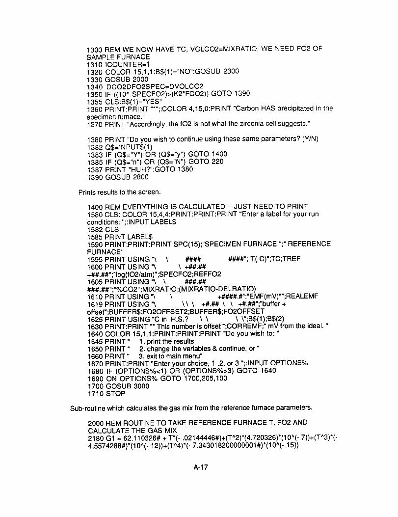
Printsresultsto thescreen.
1400REMEVERYTHINGISCALCULATED-- JUSTNEEDTO PRINT1580CLS:COLOR15,4,4:PRINT:PRINT:PRINT"Entera labelfor yourrunconditions:";:INPUTLABELS1582CLS1585PRINTLABELS1590PRINT:PRINT:PRINTSPC(15);"SPECIMENFURNACE";" REFERENCEFURNACE"1595PRINTUSING"\ \ #### ####";"T(C)";TC;TREF1600PRINTUSING'& \ +##.##+##.##";"Iog(fO2/atm)";SPECFO2;REFFO21605PRINTUSING"\ \ ###.#####.##";"%CO2";MIXRATIO;(MIXRATIO-DELRATIO)1610PRINTUSING'_ \ +####.#";"EMF(mV)*";REALEMF1619PRINTUSING"\ \\ \ +#.## \ \ +#.##";"buffer+offset";BUFFER$;FO2OFFSET2;BUFFER$;FO2OFFSET1625PRINTUSING"C in H.S.? \ \ \ V';B$(1);B$(2)1630 PRINT:PRINT "* This number is offset ";CORREMF;" mV from the ideal. "1640 COLOR 15,1,1 :PRINT:PRINT:PRINT "Do you wish to: "1645 PRINT" 1. print the results1650 PRINT" 2. change the variables & continue, or"1660 PRINT" 3. exitto main menu"1670 PRINT:PRINT "Enter your choice, 1 ,2, or 3.";:INPUT OPTIONS%1680 IF (OPTIONS%<1) OR (OPTIONS%>3) GOTO 16401690 ON OPTIONS% GOTO 1700,205,1001700 GOSUB 30001710 STOP
Sub-routine which calculates the gas mix from the reference furnace parameters.
2000 REM ROUTINE TO TAKE REFERENCE FURNACE T, FO2 ANDCALCULATE THE GAS MIX2180 G1 = 62.110326# + T*(- .02144446#)+(T^2)*(4.720326)*(10^( - 7))+(T"3)*(-4.5574288#)*(10*(- 12))+(T^4)*( - 7.343018200000001 #)*(10^( - 15))
A-17
2190G2-- 94.25770200000001#+ T*(7.321945)*(10^(-4))_(T^2)*(10^(_7))*(3.416474)+(T^3)*(4.7858617#)*(10^(- 11))2200K1= EXP(-G1/(R*(T+ 273.18))):K2= EXP,-G2/(R*(T+ 273.18)))2210 A =(K1-(SQR(10^LOGFO2))*FNRM(K1,LOGFO2))/(K1+SQR(10^LOGFO2))2220FCO2= 2"(1 - A)/(2+ A + 2*FNRM(K1,LOGFO2))2230VOLCO2= 100/(1 + FNRM(K1,LOGFO2)):DVOLCO2=100/(1+FNRM(K1,(LOGFO2+.1)))-100/(1+FNRM(K1,(LOGFO2-.1)))2240RETURN
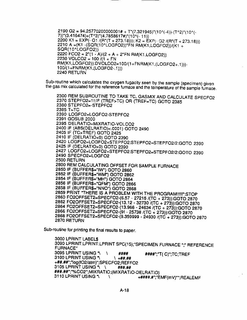
Sub-routinewhichcalculatestheoxygenfugacityseenbythesample(specimen)giventhegasmixcalculatedforthereferencefurnaceandthetemperatureof thesamplefurnace.
2300237023802385239023912395240024052410242024252427249025002800285028522854285628582859286028622864286628682870
REMSUBROUTINETO TAKETC,GASMIXANDCALCULATESPECFO2STEPFO2=I!:IF (TREF>TC)OR (TREF=TC)GOTO2385STEPFO2=-STEPFO2T=TCLOGFO2=LOGFO2-STEPFO2GOSUB2000DELRATIO=MIXRATIO-VOLCO2IF (ABS(DELRATIO)<.0001)GOTO2490IF (TC>TREF)GOTO2425IF (DELRATIO<0)GOTO2390LOGFO2=LOGFO2+STEPFO2:STEPFO2=STEPFO2/2:GOTO2390IF (DELRATIO>0)GOTO2390LOGFO2=LOGFO2+STEPFO2:STEPFO2=STEPFO2/2:GOTO2390SPECFO2--LOGFO2RETURNREMCALCULATINGOFFSETFORSAMPLEFURNACEIF (BUFFER$="IW")GOTO2860IF (BUFFER$="WM")GOTO2862IF (BUFFER$="MH")GOTO2864IF (BUFFER$="QFM")GOTO2866IF (BUFFER$="NNO")GOTO2868PRINT"THEREISA PROBLEMWiTHTHE PROGRAM!!H!":STOPFO2OFFSET2=SPECFO2-(6.57- 27215/(TC + 273)):GOTO2870FO2OFFSET2=SPECFO2-(13.12- 32730/(TC+ 273)):GOTO2870FO2OFFSET2=SPECFO2-(13.966- 24634/(TC+ 273)):GOTO2870FO2OFFSET2=SPECFO2-(g!- 25738/(TC+ 273)):GOTO2870FO2OFFSET2=SPECFO2-(9.359999- 24930/(TC + 273)):GOTO2870RETURN
Sub-routinefor printingthefinalresultsto paper.
3000LPRINTLABELS3090LPRINT:LPRINT:LPRINTSPC(15);"SPECIMENFURNACE";" REFERENCEFURNACE"3095LPRINTUSING"\ \ #### ####";"T(C)";TC;TREF3100LPRINTUSING"_ \ +##.##+##.##";"Iog(fO2/atm)";SPECFO2;REFFO23105LPRINTUSING"_ \ ###.#####.##";"%CO2";MIXRATIO;(MIXRATIO-DELRATIO)3110LPRINTUSING'_ \ +####.#";"EMF(mV)*";REALEMF
A-18

3119LPRINTUSING"\ \\ \ +#.## \ \ +#.##":"buffer+offset";BUFFER$;FO2OFFSET2;BUFFER$;FO2OFFSET3125LPRINTUSING"C in H.S.? \ \ _,":B$(1);B$(2)3130LPRINT:LPRINT"* Thisnumberisoffset";CORREMF;"mVfromtheideal."3135 IF (PRINTER$="EPSON")GOTO31383137 LPRINTCHR$(12);:GOTO31403138LPRINT:LPRINT3140CLS3150RETURN1640
A-19
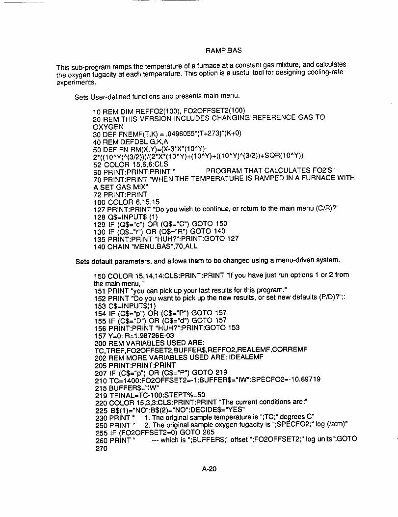
RAMP.BAS
Thissub-programrampsthetemperatureof afurnaceata constantgasmixture,andcalculatestheoxygenfugacityat eachtemperature.Thisoptionisa usefultoolfordesigningcooling-rateexperiments.
SetsUser-definedfunctionsandpresentsmainmenu.
10REMDIMREFFO2(100),FO2OFFSET2(100)20 REMTHISVERSIONINCLUDESCHANGINGREFERENCEGASTOOXYGEN30 DEFFNEMF(T,K)=.0496055*(T+273)*(K+0)40 REMDEFDBLG,K,A50DEFFNRM(X,Y)=(X-3*X*(10^Y)-2"((10^Y)̂ (3/2)))/(2"X*(10̂Y)+(10^Y)+((10̂ Y)̂ (3/2))+SQR(10^Y))52 COLOR15,6,6:CLS60 PRINT:PRINT:PRINT" PROGRAMTHATCALCULATESFO2'S"70 PRINT:PRINT"WHENTHETEMPERATUREISRAMPEDINA FURNACEWITHA SETGASMIX"72 PRINT:PRINT100 COLOR6,15,15127PRINT:PRINT"Doyouwishto continue,or returnto themainmenu(C/R)?"128Q$=INPUT$(1)129 IF (Q$="c")OR (Q$="C")GOTO150130 IF (Q$="r")OR (Q$="R")GOTO140135 PRINT:PRINT"HUH?":PRINT:GOTO127140CHAIN"MENU.BAS",70,ALL
Sets default parameters, and allows them to be changed using a menu-driven system.
150 COLOR 15,14,14:CLS:PRINT:PRINT "If you have just run options 1 or 2 fromthe main menu,"151 PRINT "you can pick up your last results for this program."152 PRINT "Do you want to pick up the new results, or set new defaults (P/D)?";:153 C$=INPUT$(1 )154 IF (C$="p") OR (C$="P") GOTO 157155 IF (C$="D") OR (C$="d") GOTO 157156 PRINT:PRINT "HUH?":PRINT:GOTO 153157 Y=0: R=1.98726E-03200 REM VARIABLES USED ARE:TC,TREF,FO2OFFSET2,BUFFER$,REFFO2,REALEMF,CORREMF202 REM MORE VARIABLES USED ARE: IDEALEMF205 PRINT:PRINT:PRINT207210215219220225230250255260270
IF (C$="p") OR (C$="P") GOTO 219TC=1400:FO2OFFSET2=- 1:BU FFER$="IW":S PEC FO2=- 10.69719BUFFER$="IW"TFINAL=TC-100:STEPT%=50COLOR 15,3,3:CLS:PRINT:PRINT "The current conditions are:"B$(1 )="NO":B$(2)="NO":DECIDE$="YES"PRINT" 1. The original sample temperature is ";TC;" degrees C"PRINT" 2. The original sample oxygen fugacity is ";SPECFO2;" log (/atm)"IF (FO2OFFSET2=0) GOTO 265PRINT" --- which is ";BUFFERS;" offset ";FO2OFFSET2;" log units":GOTO
A-20
265 PRINT" ---which is ";BUFFERS270 PRINT" 3. Final temperature is ";TFINAL;" degrees C"280 PRINT " --- and fO2's will be printed for e,,,e_v ";STEPT%;" degrees"300 PRINT "and 4. The reference buffer is ";BUFFERS320 PRINT:PRINT:PRINT
380 COLOR 15,9,9:PRINT "Please enter a number: 1 - 4 for changes; 5 to continue;6 to exit.";:390 INPUT .... ,CHANGE%400 IF (CHANGE%>0) AND (CHANGE%<7) GOTO 420410 PRINT:COLOR 31,9,9:PRINT .....;:GOTO 380420 CLS:ON CHANGE% GOTO 430,580,440,487,1000,140430 INPUT "Enter the new sample temperature in degrees C";TC431 IF (BUFFER$="IW") GOTO 850432 IF (BUFFER$="WM") GOTO 851433 IF (BUFFER$="MH") GOTO 852434 IF (BUFFER$="QFM") GOTO 853435 IF (BUFFER$="NNO") GOTO 854436 PRINT "ERROR IN PROGRAM/NO BUFFER":STOP440 INPUT "Enter the final temperature in degrees C";TFINAL450 INPUT "Enter the interval for which you want fO2's printed";STEPT%:CLS:GOTO 220460 CLS:PRINT:PRINT:PRINT
470 PRINT "The sample fO2 data will be given as relative to a buffer, as well"480 PRINT "as in Iog(fO2/atm) units. Your choice of 'reference buffers' are:"485 GOTO 490487 CLS:PRINT:PRINT:PRINT:PRINT "Your choice of reference buffers are:"490 PRINT:PRINT" 1. IW"500 PRINT" 2. WM"510 PRINT" 3. MH"520 PRINT" 4. QFM"530 PRINT" 5. NNO"
535 PRINT:PRINT "(Your current choice is )";BUFFERS540 PRINT:PRINT "Enter the number of your selection."550 INPUT .... ,CHANGE%560 IF (CHANGE%<1) OR (CHANGE%>5) GOTO 460570 ON CHANGE% GOTO 571,572,573,574,575571 BUFFER$="IW":GOTO 850572 BUFFER$="WM":GOTO 851573 BUFFER$--"MH":GOTO 852574 BUFFER$="QFM":GOTO 853575 BUFFER$="NNO":GOTO 854580 CLS590 PRINT:PRINT:PRINT
600 PRINT "The sample furnace fO2 can be expressed as any of three ways:"610 PRINT:PRINT" 1. as a standard buffer"620 PRINT" 2. as offset from a standard buffer"630 PRINT" 3. as a specific fO2 (independent of any buffer) "650 PRINT:PRINT "How would you like to express your new fO2"660 PRINT" (Enter 1-3, or 4 for unchanged)."670 INPUT .... ,CHANGE%680 IF (CHANGE%<1) OR (CHANGE%>4) GOTO 590690 ON CHANGE% GOTO 700,700,820,692692 CLS:GOTO 220700 PRINT:PRINT "Your choices of standard reference buffers are:":PRINT
A-21
701 PRINT"1. IW"702 PRINT" 2. WM"703 PRINT" 3. MH"704 PRINT" 4. QFM"705 PRINT" 5. NNO"706 PRINT" 6. noneabove.Returnto previousmenu."710PRINT:PRINT"Enterthenumberofyourselection.";:720 INPUT.... ,CHOICE%730 IF (CHOICE%<1)OR (CHOICE%>6)GOTO710740 FO2OFFSET2=0:IF(CHANGE%=1)GOTO760750 INPUT"Entertheoffsetfromthebuffer,in log(fO2/atm)units.",FO2OFFSET2760 ON CHOICE%GOTO770,780,790,800,810,580770 SPECFO2= 6.57- 27215/(TC+273)+FO2OFFSET2:BUFFER$="IW":CLS:GOTO220780 SPECFO2= 13.12- 32730/(TC+273)+FO2OFFSET2:BUFFER$="WM":CLS:GOTO220790 SPECFO2= 13.966- 24634/(TC+273)+FO2OFFSET2:BUFFER$="MH":CLS:GOTO220800 SPECFO2= 9! - 25738/(TC+273)+FO2OFFSET2:BUFFER$="QFM":CLS:GOTO220810SPECFO2= 9.359999- 24930/(TC+273)+FO2OFFSET2:BUFFER$="NNO":CLS:GOTO220820 CLS830 PRINT:PRINT"Whatis the logof thef02youwant?";:840 INPUTSPECFO2:GOTO431850 FO2OFFSET2=SPECFO2-(6.57- 27215/(TC + 273)):CLS:GOTO220851 FO2OFFSET2=SPECFO2-(13.12- 32730/(TC + 273)):CLS:GOTO220852 FO2OFFSET2=SPECFO2-(13.966- 24634/(TC + 273)):CLS:GOTO220853 FO2OFFSET2=SPECFO2-(9!- 25738/(TC+ 273)):CLS:GOTO220854 FO2OFFSET2--SPECFO2-(9.359999- 24930/(TC + 273)):CLS:GOTO220
Given the initial conditions in the sample furnace, the cooling rate, and the temperature of thereference furnace, the other parameters of interest can be calculated using sub-routines.
1000 COLOR 15,6,6:CLS1001 REM NOW TC,TFINAL,STEPT,FO2 HAS BEEN INPUT1010 REM SUBROUTINE AT 1750 CALCULATES GASMIXTURES, 1830 = CSTABILITY1020 REM SUBROUTINE AT 1100 CALCULATES EMF'S1030 REM SUBROUTINE AT 1380 CALCULATES DELEMFDELT; 1680 =DEMFDFO21031 REM SUBROUTINE AT 1530 ITERATES REFERENCE FURNACE FO21032 PRINT:PRINT:PRINT "Enter a label for this calculation: ";:INPUT LABELS1034 COLOR 15,1,1 :CLS:PRINT:PRINT:PRINT "WORKING ... PLEASE BEPATIENT"1035 PRINT:PRINT:PRINT:PRINT:PRINT:PRINT:PRINT LABELS1040 T=TC:LOGFO2=SPECFO2:GOSUB 17601050 MIXRATIO=VOLCO21057 PRINT:PRINT "For a constant gas mix of ";:PRINT USING"###.##";MIXRATIO:PRINT:PRINT "T";SPC(5);"logfO2";SPC(2);"Buffer + offset"1060 IF (VOLCO2>100)GOTO 12901070 IF (TFINAL>TC) GOTO 10751073 STEPT%=-STEPT%1074 I1=0
A-22
1075FORI=TCTOTFINALSTEPSTEPT%1078TREF=I:II=I1+1:GOSUB15301079GOSUB18301080PRINTUSING" #### +##.##\ \+#.##";TREF;REFFO2;BUFFER$;FO2OFFSET21085FO2OFFSET2(I1)=FO2OFFSET2:REFFO2(I1)=REFFO2109011001101111011201130113511401150120012901300130113101320133013401350136013651370
NEXTIPRINT:PRINT"Doyouwishto Printtheresults,Continuewiththisprogram,PRINT" or Returnto themainmenu?(P/C/R)"P$=INPUTS(1)IF (P$="r")OR (P$="R")GOTO1360IF (P$="c")OR (P$="C")GOTO1350IF(P$="P")OR (P$="p")GOTO1150PRINT:PRINT:PRINT"Huh?":PRINT:GOTO1100GOSUB2000GOTO1300PRINT"Thegasmixis unrealistic(eg.,";VOLCO2;"%).Try again."PRINT:PRINT"Doyouwishto continuewiththisprogram,°'PRINT" orreturntothemainmenu?(C/R)"P$=INPUTS(1)IF (P$="r")OR (P$="R")GOTO1360IF (P$="c")OR (P$="C")GOTO1350PRINT:PRINT:PRINT"Huh?":PRINT:GOTO1300CLS:GOTO220CLSCHAIN"MENU.BAS",70,ALLEND
Sub-routineforcalculatingthechangeinoxygenfugacitywithchangein temperatureforsmallchangesintemperature.
1380Z = 11390RATIO= FCO2/(1-FCO2-10^REFFO2)1400AA =(1- 2*RATIO*(100/ MIXRATIO - 1))/(1 + 2"(100 / MIXRATIO - 1))1410 PART = LOG(1 - AA)- LOG(100 / MIXRATIO - 1)1420 FOR I= 1 TO- 1 STEP -21430 H = I1440 W -- T + H1450 GG = 62.110326# - .02144446#*W + 4.720326E-07*(W ^ 2)+(-4.5574288#)*(10^( - 12))*(W ^ 3)- 7.343018200000001#*(10^( - 15))*( w^ 4)1460 KK = EXP(- GG/(R*(W + 273.18)))1470 Q(Z)= KK1480 Z = Z+ 11490 NEXT I1500 NEWFO21 = LOG(10)*.5*(LOG(Q(1))+ PART):NEWFO22 =LOG(10)*.5*(LOG(Q(2))+ PART)1510 DELEMFDELT =(FN EMF (TREF + 1,NEWFO21) - FN EMF (TREF - 1,NEWFO22))/21520 RETURN
Sub-routine to calculate the oxygen fugacity for the reference furnace.
1530 REM SUBROUTINE TO ITERATIVELY CALCULATE THE FO2 OF THEREFERENCE FURNACE
A-23

154015501560157015801590160016101620163016401650
STEPFO2=I {:IF (TC>TREF) GOTO 1570IF (TC=TREF) GOTO 1570STEPFO2=-STEPFO2T=TREFLOGFO2=LOGFO2-STEPFO2:GOSUB 1760DELRATIO=MIXRATIO-VOLCO2IF ABS(DELRATIO)<.001 GOTO 1660IF (TREF>TC) GOTO 1640IF (DELRATIO<0) GOTO 1580LOGFO2=LOGFO2+STEPFO2:STEPFO2=STEPFO2/2:GOTO 1580IF (DELRATIO>0) GOTO 1580LOGFO2=LOGFO2+STEPFO2:STEPFO2=STEPFO2/2:GOTO 1580
1660 REFFO2=LOGFO21670 RETURN
Sub-routine to calculate the EMF of the zirconia cell, and how it changes with smallfluctuations in temperature and oxygen fugacity.
1680 REM NOW THAT WE HAVE TEMPERATURE AND LOGFO2, WE NEED TOCALCULATE THE EMF'S AND DELTA-EMF'S1690 IDEALEMF = FN EMF (TREF,REFFO2)1700 DELEMFDELFO2 =( FN EMF (TREF,(REFFO2 + .1))- FN EMF(TREF,(REFFO2 - .1)))/21740 RETURN
Sub-routine for calculating the gas mixture.
1750 REM NOW WE WANT TO TAKE THE T, FO2 CONDITIONS & COMPUTETHE %CO2
1760 G 1 = 62.110326# + T*(- .02144446#)+(Th2)*(4.720326)*(10h( - 7))+(T^3)*(-4.5574288#)*(10h(- 12))+(T*4)*(- 7.343018200000001#)*(10h(- 15))1770 G2 = 94.25770200000001# + T*(7.321945)*(10h('4))-(Th2)*(10h(-7))*(3.416474)+(T*3)*(4.7858617#)*(10h( - 11))1780 K1 = EXP(- G1/(R*(T + 273.18))): K2 = EXP(- G2/(R*(T + 273.18)))1790 A =(K1 -(SQR(10ALOGFO2))*FN RM(K1 ,LOGFO2))/(K1 +SQR(10hLOGFO2))1800 FCO2 = 2"(1 - A)/(2 + A + 2*FN RM(K1 ,LOGFO2))1810 VOLCO2 = 100/(1 + FNRM(K1, LOG FO2)) :DVOLCO2= 100/(1 +FN RM(K1, (LOGFO2+. 1)))-100/(1 +FN R M(K 1,(LOGFO2-. 1)))1820 RETURN
Sub-routine for comparing the oxygen fugacities in the sample and reference furnaces witha standard buffer.
183018311832183318341835185018511852
REM CALCULATING FO2OFFSETIF (BUFFER$="IW") GOTO 1850IF (BUFFER$="WM") GOTO 1851IF (BUFFER$="MH") GOTO 1852IF (BUFFER$="QFM") GOTO 1853IF (BUFFER$="NNO") GOTO 1854FO2OFFSET2=REFFO2-(6.57 - 27215/(TREF + 273)):GOTO 1860FO2OFFSET2=REFFO2-(13.12 - 32730/(TREF + 273)):GOTO 1860FO2OFFSET2=REFFO2-(13.966 - 24634/(TREF + 273)):GOTO 1860
A-24
1853FO2OFFSET2=REFFO2-(9!-25738/(TREF+ 273)):GOTO18601854FO2OFFSET2=REFFO2-(9.359999- 24930/(TREF+ 273))1860RETURN
Sub-routinefor printingtheresultsto paper.
2000REMPRINTINGSUBROUTINE2035LPRINTLABEL$:LPRINT:LPRINT"(atconstantgasmixof ";:LPRINTUSING"###.##";MIXRATIO;:LPRINT")":LPRINT:LPRINT"T";SPC(5);"logfO2";SPC(2);"Buffer+ offset"2040J1=02050 FORJ=TCTO TFINALSTEPSTEPT%2060TPRINT=J:JI=JI+I2080LPRINTUSING"#### +##.##\ \+#.##";TPRINT;REFFO2(J1);BUFFER$;FO2OFFSET2(J1)2100NEXTJ2110 IF (PRINTER$="EPSON")GOTO21252120 LPRINTCHR$(12);:GOTO21272125LPRINT:LPRINT2127CLS2130RETURN
A-25
Form ApprovedREPORT DOCUM ENTATION PAGE OMB_o.OZO_-OTBB
PubliC reporting burden for this collection of information is estimated to average 1 hour per recjx>nse, including the trme for re_q_wmg instructions, searching existing data sources, gathering andmaintaining the data needed, and completing and reviewing the collection of information Send comments regarding 1his burden estimate or any other aspect of _his coltectlon of informattonincluding suggestions for reducing this burden, to Washington Headquarters Services, Directorate for Information Operations ano Reoorts, 1215 Jefferson Davis Highway, Suite 1204, Arhngton, VA22202-4302. and to the Office of Management and Budget, paperwork Reduction Proiect {0704-0188}, Washington. DC 205G3
1, AGENCY USE ONLY (Leave blank) 2. REPORT DATE 3. REPORT TY oE AND DATES COVERED
September 1993 interim
4. TITLE AND SUBTITLE
Technical Update: JSC System Using a SolidElectrolyticCell ina RemoteLocation toMeasure Oxygen Fugacitiesin CO/CO2 Controlled-Atmosphere
Furnaces
6 AUTHOR(S)
A. J.G. Jurewicz, R. J.Williams, L.Le, J.Wagstaff, G. Lofgren,A. Lanier,
W. Carter,A. Roshko
PERFORMING ORGANIZATION NAME(S) AND ADDRESS(ES)
Lyndon B.Johnson Space Center
Houston, TX 77058
SPONSORING/ MONITORINGAGENCYNAME(S)AND ADDRESS(ES)National Aeronautics and Space Administration
Washington. D.C. 20546
S. FUNDING NUMBERS
NAS 9-11410F
8. PERFORMING ORGANIZATIONREPORT NUMBER
S-727
10. SPONSORING / MONITORINGAGENCY REPORT NUMBER
TM-104774
11. SUPPLEMENTARY NOTES
12a. DISTRIBUTION/AVAILABILITYSTATEMENTNational Technical Informatin Service
5285 Port Royal Road
Springfield,VA 22161(703)487-4600
SubjectCategory: 88 Space Sciences General
12b. DISTRIBUTION CODE
13. ABSTRACT (Maximum 200 words)
Detailsare given forthe design and applicationofa (one atmosphere) redox-controlsystem. This system differsfrom
that given in NASA Technical Memorandum 58234 inthat ituses a singlesolid-electrolyticcellina remote location
tomeasure the oxygen fugacitiesofmultiple CO/CO2 controlled-atmosphere furnaces. This remote measurement
(1)extends the range ofsample-furnace conditionsthat can be measured using a solid-electrolyticcell,and (2)cuts
costsby extending the lifeofthe sensors and by minimizing the number ofsensorsinuse. The system consistsofareferencefurnace and an exhaust-gas manifold. The referencefurnace isdesigned according tothe redox control
system ofNASA Technical Memorandum 58234, and any number ofCO/CO2 controlled-atmospherefurnaces can beattached tothe exhaust-gas manifold. Using the manifold,the exhaust gas from individualCO/CO2 controlled-
atmosphere furnaces can be diverted through the referencefurnace,where a solid-electrolytecellisused toread the
ambient oxygen fugacity.The oxygen fugacitymeasured inthe referencefurnace can then be used tocalculatethe
oxygen fugacityinthe individualCO/CO2 controlled-atmospherefurnace. A BASIC computer program was
developed toexpedite thiscalculationand isavailablefrom the firstauthor.
14. SUBJECT TERMS
furnaces,controlled-atmosphere;oxygen fugacity;electrolyticcell(solid);redox cells
(controlsystem)
17. SECURITY CLASSIFICATION 18. SECURITY CLASSIFICATION 19. SECURITY CLASSIFICATIONOF REPORT OF THIS PAGE OF ABSTRACT
Unclassified Unclassified Unclassified
15. NUMBER OF PAGES
37
16. PRICE CODE
20. LIMITATION OF ABSTRACT
Unlimited
Standard Form 298 (Ray. 2-8g)Prescribed by ANSI Std. 239-18298-102