Embed Size (px)
Citation preview

JSX 212
For information on other great Peavey products, visit your local Peavey dealer or visit us online at www.peavey.com
™ Joe Satriani Signature All-Tube Amplifier

2
Intended to alert the user to the presence of uninsulated “dangerous voltage” within the product’s enclosure that may be of sufficient magnitude to constitute a risk of electric shock to persons.
Intended to alert the user of the presence of important operating and maintenance (servicing) instructions in the literature accompanying the product.
CAUTION: Risk of electrical shock — DO NOT OPEN! CAUTION: To reduce the risk of electric shock, do not remove cover. No user serviceable parts inside. Refer servicing to qualified service personnel.
WARNING: To prevent electrical shock or fire hazard, do not expose this appliance to rain or moisture. Before using this appliance, read the operating guide for further warnings.
Este símbolo tiene el propósito, de alertar al usuario de la presencia de “(voltaje) peligroso” sin aislamiento dentro de la caja del producto y que puede tener una magnitud suficiente como para constituir riesgo de descarga eléctrica.
Este símbolo tiene el propósito de alertar al usario de la presencia de Instrucciones importantes sobre la operación y mantenimiento en la información que viene con el producto.
PRECAUCION: Riesgo de descarga eléctrica ¡NO ABRIR! PRECAUCION: Para disminuír el riesgo de descarga eléctrica, no abra la cubierta. No hay piezas útiles dentro. Deje todo mantenimiento en manos del personal técnico cualificado.
ADVERTENCIA: Para evitar descargas eléctricas o peligro de incendio, no deje expuesto a la lluvia o humedad este aparato Antes de usar este aparato, Iea más advertencias en la guía de operación.
Ce symbole est utilisé dans ce manuel pour indiquer à l’utilisateur la présence d’une tension dangereuse pouvant être d’amplitude suffisante pour constituer un risque de choc électrique.
Ce symbole est utilisé dans ce manuel pour indiquer à l’utilisateur qu’il ou qu’elle trouvera d’importantes instructions concernant l’utilisation et l’entretien de l’appareil dans le paragraphe signalé.
ATTENTION: Risques de choc électrique — NE PAS OUVRIR!ATTENTION: Afin de réduire le risque de choc électrique, ne pas enlever le couvercle. Il ne se trouve à l’intérieur aucune pièce pouvant être reparée par l’utilisateur. Confiez I’entretien et la réparation de l’appareil à un réparateur Peavey agréé.
AVERTISSEMENT: Afin de prévenir les risques de décharge électrique ou de feu, n’exposez pas cet appareil à la pluie ou à l’humidité. Avant d’utiliser cet appareil, lisez attentivement les avertissements supplémentaires de ce manuel.
Dieses Symbol soll den Anwender vor unisolierten gefährlichen Spannungen innerhalb des Gehäuses warnen, die von Ausreichender Stärke sind, um einen elektrischen Schlag verursachen zu können.
Dieses Symbol soll den Benutzer auf wichtige Instruktionen in der Bedienungsanleitung aufmerksam machen, die Handhabung und Wartung des Produkts betreffen.
VORSICHT: Risiko — Elektrischer Schlag! Nicht öffnen! VORSICHT: Um das Risiko eines elektrischen Schlages zu vermeiden, nicht die Abdeckung enfernen. Es befinden sich keine Teile darin, die vom Anwender repariert werden könnten. Reparaturen nur von qualifiziertem Fachpersonal durchführen lassen.
ACHTUNG: Um einen elektrischen Schlag oder Feuergefahr zu vermeiden, sollte dieses Gerät nicht dem Regen oder Feuchtigkeit ausgesetzt werden. Vor Inbetriebnahme unbedingt die Bedienungsanleitung lesen.

3
IMPORTANT SAFETY INSTRUCTIONS
WARNING: When using electrical products, basic cautions should always be followed, including the following:1. Read these instructions.
2. Keep these instructions.
3. Heed all warnings.
4. Follow all instructions.
5. Do not use this apparatus near water.
6. Clean only with a dry cloth.
7. Do not block any of the ventilation openings. Install in accordance with manufacturer’s instructions.
8. Do not install near any heat sources such as radiators, heat registers, stoves or other apparatus (including amplifiers) that produce heat.
9. Do not defeat the safety purpose of the polarized or grounding-type plug. A polarized plug has two blades with one wider than the other. A grounding type plug has two blades and a third grounding plug. The wide blade or third prong is provided for your safety. If the provided plug does not fit into your outlet, consult an electrician for replacement of the obsolete outlet.
10. Protect the power cord from being walked on or pinched, particularly at plugs, convenience receptacles, and the point they exit from the apparatus.
11. Only use attachments/accessories provided by the manufacturer.
12. Use only with a cart, stand, tripod, bracket, or table specified by the manufacturer, or sold with the apparatus. When a cart is used, use caution when moving the cart/apparatus combination to avoid injury from tip-over.
13. Unplug this apparatus during lightning storms or when unused for long periods of time.
14. Refer all servicing to qualified service personnel. Servicing is required when the apparatus has been damaged in any way, such as power-supply cord or plug is damaged, liquid has been spilled or objects have fallen into the apparatus, the apparatus has been exposed to rain or moisture, does not operate normally, or has been dropped.
15. Never break off the ground pin. Write for our free booklet “Shock Hazard and Grounding.” Connect only to a power supply of the type marked on the unit adjacent to the power supply cord.
16. If this product is to be mounted in an equipment rack, rear support should be provided.
17. Note for UK only: If the colors of the wires in the mains lead of this unit do not correspond with the terminals in your plug‚ proceed as follows:
a) The wire that is colored green and yellow must be connected to the terminal that is marked by the letter E‚ the earth symbol‚ colored green or colored green and yellow.
b) The wire that is colored blue must be connected to the terminal that is marked with the letter N or the color black.
c) The wire that is colored brown must be connected to the terminal that is marked with the letter L or the color red.
18. This electrical apparatus should not be exposed to dripping or splashing and care should be taken not to place objects containing liquids, such as vases, upon the apparatus.
19. Exposure to extremely high noise levels may cause a permanent hearing loss. Individuals vary considerably in suscep-tibility to noise-induced hearing loss, but nearly everyone will lose some hearing if exposed to sufficiently intense noise for a sufficient time. The U.S. Government’s Occupational Safety and Health Administration (OSHA) has specified the following permissible noise level exposures:
Duration Per Day In Hours Sound Level dBA, Slow Response 8 90 6 92 4 95 3 97 2 100 1 1⁄2 102 1 105 1⁄2 110 1⁄4 or less 115
According to OSHA, any exposure in excess of the above permissible limits could result in some hearing loss. Ear plugs or protectors to the ear canals or over the ears must be worn when operating this amplification system in order to prevent a permanent hearing loss, if exposure is in excess of the limits as set forth above. To ensure against potentially dangerous exposure to high sound pressure levels, it is recommended that all persons exposed to equipment capable of producing high sound pressure levels such as this amplification system be protected by hearing protectors while this unit is in operation.
SAVE THESE INSTRUCTIONS!

4
WICHTIGE SICHERHEITSHINWEISE
ACHTUNG: Beim Einsatz von Elektrogeräten müssen u.a. grundlegende Vorsichtsmaßnahmen befolgt werden:1. Lesen Sie sich diese Anweisungen durch.
2. Bewahren Sie diese Anweisungen auf.
3. Beachten Sie alle Warnungen.
4. Befolgen Sie alle Anweisungen.
5. Setzen Sie dieses Gerät nicht in der Nähe von Wasser ein.
6. Reinigen Sie es nur mit einem trockenen Tuch.
7. Blockieren Sie keine der Lüftungsöffnungen. Führen Sie die Installation gemäß den Anweisungen des Herstellers durch.
8. Installieren Sie das Gerät nicht neben Wärmequellen wie Heizungen, Heizgeräten, Öfen oder anderen Geräten (auch Verstärkern), die Wärme erzeugen.
9. Beeinträchtigen Sie nicht die Sicherheitswirkung des gepolten Steckers bzw. des Erdungssteckers. Ein gepolter Stecker weist zwei Stifte auf, von denen einer breiter ist als der andere. Ein Erdungsstecker weist zwei Stifte und einen dritten Erdungsstift auf. Der breite Stift bzw. der dritte Stift dient Ihrer Sicherheit. Sollte der beiliegende Stecker nicht in Ihre Steckdose passen, wenden Sie sich bitte an einen Elektriker, um die ungeeignete Steckdose austauschen zu lassen.
10. Schützen Sie das Netzkabel, sodass niemand darauf tritt oder es geknickt wird, insbesondere an Steckern oder Buchsen und ihren Austrittsstellen aus dem Gerät.
11. Verwenden Sie nur die vom Hersteller erhältlichen Zubehörgeräte oder Zubehörteile.
12. Verwenden Sie nur einen Wagen, Stativ, Dreifuß, Träger oder Tisch, der den Angaben des Herstellers entspricht oder zusammen mit dem Gerät verkauft wurde. Wird ein Wagen verwendet, bewegen Sie den Wagen mit dem darauf befindlichen Gerät besonders vorsichtig, damit er nicht umkippt und möglicherweise jemand verletzt wird.
13. Trennen Sie das Gerät während eines Gewitters oder während längerer Zeiträume, in denen es nicht benutzt wird, von der Stromversorgung.
14. Lassen Sie sämtliche Wartungsarbeiten von qualifizierten Kundendiensttechnikern durchführen. Eine Wartung ist erforderlich, wenn das Gerät in irgendeiner Art beschädigt wurde, etwa wenn das Netzkabel oder der Netzstecker beschädigt wurden, Flüssigkeit oder Gegenstände in das Gerät gelangt sind, das Gerät Regen oder Feuchtigkeit ausgesetzt wurde, nicht normal arbeitet oder heruntergefallen ist.
15. Der Erdungsstift darf nie entfernt werden. Auf Wunsch senden wir Ihnen gerne unsere kostenlose Broschüre „Shock Hazard and Grounding“ (Gefahr durch elektrischen Schlag und Erdung) zu. Schließen Sie nur an die Stromversorgung der Art an, die am Gerät neben dem Netzkabel angegeben ist.
16. Wenn dieses Produkt in ein Geräte-Rack eingebaut werden soll, muss eine Versorgung über die Rückseite eingerichtet werden.
17. Hinweis – Nur für Großbritannien: Sollte die Farbe der Drähte in der Netzleitung dieses Geräts nicht mit den Klemmen in Ihrem Stecker übereinstimmen, gehen Sie folgendermaßen vor:
a) Der grün-gelbe Draht muss an die mit E (Symbol für Erde) markierte bzw. grüne oder grün-gelbe Klemme angeschlossen werden.
b) Der blaue Draht muss an die mit N markierte bzw. schwarze Klemme angeschlossen werden.
c) Der braune Draht muss an die mit L markierte bzw. rote Klemme angeschlossen werden.
18. Dieses Gerät darf nicht ungeschützt Wassertropfen und Wasserspritzern ausgesetzt werden und es muss darauf geachtet werden, dass keine mit Flüssigkeiten gefüllte Gegenstände, wie z. B. Blumenvasen, auf dem Gerät abgestellt werden.
19. Belastung durch extrem hohe Lärmpegel kann zu dauerhaftem Gehörverlust führen. Die Anfälligkeit für durch Lärm bedingten Gehörverlust ist von Mensch zu Mensch verschieden, das Gehör wird jedoch bei jedem in gewissem Maße geschädigt, der über einen bestimmten Zeitraum ausreichend starkem Lärm ausgesetzt ist. Die US-Arbeitsschutzbehörde (Occupational and Health Administration, OSHA) hat die folgenden zulässigen Pegel für Lärmbelastung festgelegt: Dauer pro Tag in Stunden Geräuschpegel dBA, langsame Reaktion
8 90 6 92 4 95 3 97 2 100 1 1Đ2 102 1 105 1Đ2 110 1Đ4 oder weniger 115
Laut OSHA kann jede Belastung über den obenstehenden zulässigen Grenzwerten zu einem gewissen Gehörverlust führen. Sollte die Belastung die obenstehenden Grenzwerte übersteigen, müssen beim Betrieb dieses Verstärkungssystems Ohrenstopfen oder Schutzvorrichtungen im Gehörgang oder über den Ohren getragen werden, um einen dauerhaften Gehörverlust zu verhindern. Um sich vor einer möglicherweise gefährlichen Belastung durch hohe Schalldruckpegel zu schützen, wird allen Personen empfohlen, die mit Geräten arbeiten, die wie dieses Verstärkungssystem hohe Schalldruckpegel erzeugen können, beim Betrieb dieses Geräts einen Gehörschutz zu tra-gen.
BEWAHREN SIE DIESE SICHERHEITSHINWEISE AUF!

5
INSTRUCTIONS IMPORTANTES DE SECURITE
ATTENTION: L’utilisation de tout appareil électrique doit être soumise aux precautions d’usage incluant:
1. Lire ces instructions.
2. Gardez ce manuel pour de futures références.
3. Prétez attention aux messages de précautions de ce manuel.
4. Suivez ces instructions.
5. N’utilisez pas cette unité proche de plans d’eau.
6. N’utilisez qu’un tissu sec pour le nettoyage de votre unité.
7. N’obstruez pas les systèmes de refroidissement de votre unité et installez votre unité en fonction des instructions de ce manuel.
8. Ne positionnez pas votre unité à proximité de toute source de chaleur.
9. Connectez toujours votre unité sur une alimentation munie de prise de terre utilisant le cordon d’alimentation fourni.
10. Protégez les connecteurs de votre unité et positionnez les cablages pour éviter toutes déconnexions accidentelles.
11. N’utilisez que des fixations approuvées par le fabriquant.
12. Lors de l’utilsation sur pied ou pole de support, assurez dans le cas de déplacement de l’ensemble enceinte/support de prévenir tout basculement intempestif de celui-ci.
13. Il est conseillé de déconnecter du secteur votre unité en cas d’orage ou de durée prolongée sans utilisation.
14. Seul un technicien agréé par le fabriquant est à même de réparer/contrôler votre unité. Celle-ci doit être contrôlée si elle a subit des dommages de manipulation, d’utilisation ou de stockage (humidité,…).
15. Ne déconnectez jamais la prise de terre de votre unité.
16. Si votre unité est destinée a etre montée en rack, des supports arriere doivent etre utilises.
17. Note pour les Royaumes-Unis: Si les couleurs de connecteurs du cable d’alimentation ne correspond pas au guide de la prise secteur, procédez comme suit:
a) Le connecteur vert et jaune doit être connectrer au terminal noté E, indiquant la prise de terre ou correspondant aux couleurs verte ou verte et jaune du guide.
b) Le connecteur Bleu doit être connectrer au terminal noté N, correspondnat à la couleur noire du guide.
c) Le connecteur marron doit être connectrer au terminal noté L, correspondant à la couleur rouge du guide.
18. Cet équipement électrique ne doit en aucun cas être en contact avec un quelconque liquide et aucun objet contenant un liquide, vase ou autre ne devrait être posé sur celui-ci.
19. Une exposition à de hauts niveaux sonores peut conduire à des dommages de l’écoute irréversibles. La suscep-tibilité au bruit varie considérablement d’un individu à l’autre, mais une large majorité de la population expériencera une perte de l’écoute après une exposition à une forte puissance sonore pour une durée prolongée. L’organisme de la santé américaine (OSHA) a produit le guide ci-dessous en rapport à la perte occasionnée:
Durée par Jour (heures) Niveau sonore moyen (dBA) 8 90 6 92 4 95 3 97 2 100 1 1Đ2 102 1 105 1Đ2 110 1Đ4 ou inférieur 115
D’après les études menées par le OSHA, toute exposition au delà des limites décrites ce-dessus entrainera des pertes de l’écoute chez la plupart des sujets. Le port de système de protection (casque, oreilette de filtrage,…) doit être observé lors de l’opération cette unité ou des dommages irréversibles peuvent être occasionnés. Le port de ces systèmes doit être observé par toutes personnes susceptibles d’être expo-sées à des conditions au delà des limites décrites ci-dessus.
GARDEZ CES INSTRUCTIONS!

6
INSTRUCCIONES IMPORTANTES PARA SU SEGURIDAD
CUIDADO: Cuando use productos electrónicos, debe tomar precauciones básicas, incluyendo las siguientes:1. Lea estas instrucciones.
2. Guarde estas instrucciones.
3. Haga caso de todos los consejos.
4. Siga todas las instrucciones.
5. No usar este aparato cerca del agua.
6. Limpiar solamente con una tela seca.
7. No bloquear ninguna de las salidas de ventilación. Instalar de acuerdo a las instrucciones del fabricante.
8. No instalar cerca de ninguna fuente de calor como radiadores, estufas, hornos u otros aparatos (incluyendo amplificadores) que produzcan calor.
9. No retire la patilla protectora del enchufe polarizado o de tipo “a Tierra”. Un enchufe polarizado tiene dos puntas, una de ellas más ancha que la otra. Un enchufe de tipo “a Tierra” tiene dos puntas y una tercera “a Tierra”. La punta ancha (la tercera ) se proporciona para su seguridad. Si el enchufe proporcionado no encaja en su enchufe de red, consulte a un electricista para que reemplaze su enchufe obsoleto.
10. Proteja el cable de alimentación para que no sea pisado o pinchado, particularmente en los enchufes, huecos, y los puntos que salen del aparato.
11. Usar solamente añadidos/accesorios proporcionados por el fabricante.
12. Usar solamente un carro, pie, trípode, o soporte especificado por el fabricante, o vendido junto al aparato. Cuando se use un carro, tenga cuidado al mover el conjunto carro/aparato para evitar que se dañe en un vuelco. No suspenda esta caja de ninguna manera.
13. Desenchufe este aparato durante tormentas o cuando no sea usado durante largos periodos de tiempo.
14. Para cualquier reparación, acuda a personal de servicio cualificado. Se requieren reparaciones cuando el aparato ha sido dañado de alguna manera, como cuando el cable de alimentación o el enchufe se han dañado, algún líquido ha sido derramado o algún objeto ha caído dentro del aparato, el aparato ha sido expuesto a la lluvia o la humedad, no funciona de manera normal, o ha sufrido una caída.
15. Nunca retire la patilla de Tierra.Escríbanos para obtener nuestro folleto gratuito “Shock Hazard and Grounding” (“Peligro de Electrocución y Toma a Tierra”). Conecte el aparato sólo a una fuente de alimentación del tipo marcado al lado del cable de alimentación.
16. Si este producto va a ser enracado con más equipo, use algún tipo de apoyo trasero.
17. Nota para el Reino Unido solamente: Si los colores de los cables en el enchufe principal de esta unidad no corresponden con los terminales en su enchufe‚ proceda de la siguiente manera:
a) El cable de color verde y azul debe ser conectado al terminal que está marcado con la letra E‚ el símbolo de Tierra (earth)‚ coloreado en verde o en verde y amarillo.
b) El cable coloreado en azul debe ser conectado al terminal que está marcado con la letra N o el color negro.
c) El cable coloreado en marrón debe ser conectado al terminal que está marcado con la letra L o el color rojo.
18. Este aparato eléctrico no debe ser sometido a ningún tipo de goteo o salpicadura y se debe tener cuidado para no poner objetos que contengan líquidos, como vasos, sobre el aparato.
19. La exposición a altos niveles de ruido puede causar una pérdida permanente en la audición. La susceptibilidad a la pérdida de audición provocada por el ruido varía según la persona, pero casi todo el mundo perderá algo de audición si se expone a un nivel de ruido suficientemante intenso durante un tiempo determinado. El Departamento para la Salud y para la Seguridad del Gobierno de los Estados Unidos (OSHA) ha especificado las siguientes exposiciones al ruido permisibles: Duración por Día en Horas Nivel de Sonido dBA, Respuesta Lenta
8 90 6 92 4 95 3 97 2 100 1 1Đ2 102 1 105 1Đ2 110 1Đ4 o menos 115
De acuerdo al OSHA, cualquier exposición que exceda los límites arriba indicados puede producir algún tipo de pérdida en la audición. Protectores para los canales auditivos o tapones para los oídos deben ser usados cuando se opere con este sistema de sonido para preve-nir una pérdida permanente en la audición, si la exposición excede los límites indicados más arriba. Para protegerse de una exposición a altos niveles de sonido potencialmente peligrosa, se recomienda que todas las personas expuestas a equipamiento capaz de producir altos niveles de presión sonora, tales como este sistema de amplificación, se encuentren protegidas por protectores auditivos mientras esta uni-dad esté operando.
GUARDE ESTAS INSTRUCCIONES!

7
Congratulations on purchasing a Peavey JSX guitar amplifier. The
JSX is a guitar player’s dream come true—an amp that delivers
superior sound quality and high performance for any style of
guitar playing. Only the finest materials are used to create this
great-sounding, rugged, tour-worthy and very unique-looking tone
machine. I hope you like this amp as much as I do!
ENGLISH
Features
• Three 12AX7 preamp tubes
• Four EL34 power amp tubes driven by a 12AX7
• Power amp convertible to accommodate four 6L6GC tubes
• Footswitchable effects loop with independent send and return controls
• Resonance and presence damping controls
• Fully adjustable noise gate circuitry on Ultra and Crunch channels
• Line out with level control
• Cabinet impedance switch (4, 8 or 16 ohms)
• Heavy duty power, standby and channel select toggle switches
• Classic-style power status indicator lamp
• Accutronics™ spring reverb
• Two specially voiced Peavey JSX SP-8 speakers
• High/low power level switch
Joe Satriani
™

8
F R O N T PA N E L
(1) POWER SWITCH
This two-way toggle switch applies mains power to the
unit. The red POWER STATUS LAMP (3) will illuminate
when this switch is in the ON position.
(2) STANDBY SWITCH
This two-way toggle switch allows the amp to be placed in STANDBY mode. In the STANDBY position
the tubes stay hot but the amplifier is not operational. Switching to the ON position places the amp in
active mode.
(3) POWER STATUS LAMP
This indicator illuminates when mains power is being supplied to the amp.
(4) PRESENCE
This is used to fine-tune the high frequency range of the speaker enclosure by varying the damping
factor of the amplifier at high frequencies.
(5) RESONANCE
This is used to fine-tune the low frequency range of the speaker enclosure by varying the damping
factor of the amplifier at low frequencies.
(6) MASTER VOLUME
This control sets the overall volume level of the amp. Once the desired balance between the three
channels in the amplifier has been achieved, the entire output level of the unit can be increased or
decreased by rotating this control. Clockwise rotation increases the level; counterclockwise rotation
decreases the level.
(7) MASTER REVERB
This controls the overall reverb level.
16
7
5
4 3
2
WARNINGTHE ON/OFF SWITCH IN THIS APPARATUS DOES NOT BREAK BOTH SIDES OF THE MAINS. HAZARDOUS ENERGY MAY BE PRESENT INSIDE THE ENCLOSURE WHEN THE POWER SWITCH IS IN THE OFF POSITION.

(8) TREBLE
On both the Ultra and Crunch channels, this control varies the high frequency response of the
amplifier. It is an active control (shelving type) and allows approximately 12 dB of boost or cut.
(9) MID
On both the Ultra and Crunch channels, this control varies the mid frequency response of the amplifier.
It is an active control (peak/notch type) and allows approximately 12 dB of boost or cut.
(10) BASS
On both the Ultra and Crunch channels, this control varies the low frequency response of the amplifier.
It is an active control (shelving type) and allows approximately 12 dB of boost or cut.
(11) VOLUMEOn all three channels, this control sets the overall level of its respective channel.
(12) GAINOn both the Ultra and Crunch channels, this controls the input volume level of the channel. Rotating this control clockwise will increase the amount of preamp distortion and sustain.
(13) CHANNEL ACTIVATION LEDsThese indicators signify which channel is active. Ultra channel activation illuminates the red LED; Crunch channel activation illuminates the yellow LED; and Clean channel activation illuminates the green LED.
(14) FAT SWITCHThese two-position toggle switches on the Ultra and Crunch channels modify the low frequency response of the amplifier and have the most noticeable effect when the guitar is "cleaned up," i.e. when the guitar's volume control is turned down. This control affects the tightness of the attack; the attack is sloppier when the switch is in the "FAT" position.
(15) NOISE GATEThis control is shared by the Ultra and Crunch channels and adjusts the effectiveness of the noise gate circuitry. Noise is reduced more as the control is turned clockwise. Avoid using high settings of the noise gate when using lower gain settings, since at these settings the decay of the note will be adversely affected.
6
9
8
8
9
10
101112
1112
13
14
1415

10
(16) TREBLEThis passive control regulates the high frequencies for the Clean channel.
(17) MIDThis passive control regulates the mid frequencies for the Clean channel.
(18) BASSThis passive control regulates the low frequencies for the Clean channel.
(19) HIGH GAIN INPUTUsed for most electronic guitars. It is 6 dB louder than the Low Gain input.
(20) LOW GAIN INPUTProvided for instruments that have extremely high outputs that tend to overdrive (distort) the High Gain input. If both inputs are used simultaneously, the output levels are the same (both are Low Gain).
(21) CHANNEL SELECT SWITCHThis three-position toggle switch allows selection between the amplifier’s three channels. LED (13) illumination indicates which channel is active. Channel switching can also be accomplished by footswitch. See the FOOTSWITCH section of this manual for explanation of switch operation. The CHANNEL SELECT SWITCH must be set in the Ultra position in order for the footswitch to operate properly.
2120
171819 16

11
R E A R PA N E L
(22) EFFECTS SEND LEVEL
This calibrated (0 – 10) control sets the level of signal being sent to external effects and/or signal
processors. Clockwise rotation increases the amount of signal being sent; counterclockwise rotation
decreases the amount. For the quietest operation, the EFFECTS SEND LEVEL should be set as high as
possible. Generally, the SEND and RETURN levels should be set in opposite proportions. If the EFFECTS
SEND LEVEL is set low, the EFFECTS RETURN LEVEL (24) should be set high to achieve unity gain.
Note: The effects loop may also be used as a footswitchable volume boost by turning both
controls to higher settings.
(23/24) EFFECTS SEND/EFFECTS RETURN
These 1/4" mono (TS) jacks allow signal to be sent to and returned from external effects and/or signal
processors. Using shielded cables with 1/4" mono (TS) phone plugs, patch from EFFECTS SEND to
the input of the external device and from the output of the external device to EFFECTS RETURN. Only
devices that do not increase signal gain should be used in this effects loop (chorus, delay, reverb, etc.).
If the footswitch is used, the EFFECTS SELECTOR (39) switch must be depressed to activate the effects
loop. See the FOOTSWITCH section of this manual for explanation of switch operation.
(25) EFFECTS RETURN LEVEL
This calibrated (0 – 10) control sets the level of signal being returned from external effects and/or
signal processors. Clockwise rotation increases the amount of signal being returned; counterclockwise
rotation decreases the amount. Again, SEND and RETURN levels should be set in opposite proportions,
with the SEND level being high and the RETURN level low to ensure the quietest operation.
(26) REMOTE SWITCH
This seven-pin DIN connector is provided for the connection of the remote footswitch. The footswitch
cable should be connected before the amp is powered up. See the FOOTSWITCH section of this manual
for an explanation of switch operation.
(27) BIAS TEST TERMINALS
These terminals are provided to measure the bias voltage of the amplifier’s power tubes. A knob
behind the back panel grille allows for adjustment. Bias adjustment should only be done by a qualified
technician.
CAUTION
FUSE FUSE
26
22
23
24
25
27
12
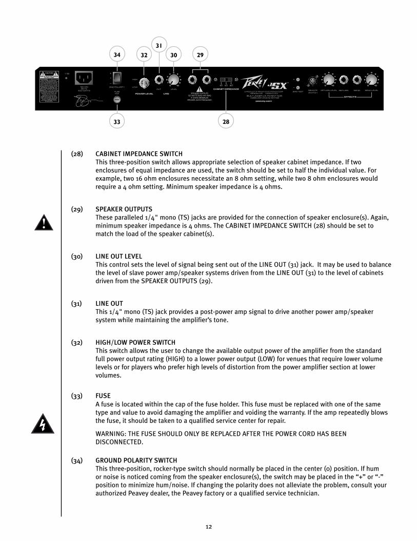
(28) CABINET IMPEDANCE SWITCHThis three-position switch allows appropriate selection of speaker cabinet impedance. If two enclosures of equal impedance are used, the switch should be set to half the individual value. For example, two 16 ohm enclosures necessitate an 8 ohm setting, while two 8 ohm enclosures would require a 4 ohm setting. Minimum speaker impedance is 4 ohms.
(29) SPEAKER OUTPUTSThese paralleled 1/4" mono (TS) jacks are provided for the connection of speaker enclosure(s). Again, minimum speaker impedance is 4 ohms. The CABINET IMPEDANCE SWITCH (28) should be set to match the load of the speaker cabinet(s).
(30) LINE OUT LEVELThis control sets the level of signal being sent out of the LINE OUT (31) jack. It may be used to balance the level of slave power amp/speaker systems driven from the LINE OUT (31) to the level of cabinets driven from the SPEAKER OUTPUTS (29).
(31) LINE OUTThis 1/4" mono (TS) jack provides a post-power amp signal to drive another power amp/speaker system while maintaining the amplifier’s tone.
(32) HIGH/LOW POWER SWITCHThis switch allows the user to change the available output power of the amplifier from the standard full power output rating (HIGH) to a lower power output (LOW) for venues that require lower volume levels or for players who prefer high levels of distortion from the power amplifier section at lower volumes.
(33) FUSE A fuse is located within the cap of the fuse holder. This fuse must be replaced with one of the same type and value to avoid damaging the amplifier and voiding the warranty. If the amp repeatedly blows the fuse, it should be taken to a qualified service center for repair.
WARNING: THE FUSE SHOULD ONLY BE REPLACED AFTER THE POWER CORD HAS BEEN DISCONNECTED.
(34) GROUND POLARITY SWITCHThis three-position, rocker-type switch should normally be placed in the center (0) position. If hum or noise is noticed coming from the speaker enclosure(s), the switch may be placed in the “+” or “-” position to minimize hum/noise. If changing the polarity does not alleviate the problem, consult your authorized Peavey dealer, the Peavey factory or a qualified service technician.
CAUTION
FUSE FUSE
33 28
2930
31
3234

13
(35) IEC MAINS CONNECTORThis is a standard IEC power connector. An AC mains cord with the appropriate AC plug and ratings for the intended operating voltage is included in the carton. The mains cord should be connected to the amplifier before connecting to a suitable AC outlet.
U.S DOMESTIC AC MAINS CORDThe mains cord supplied with the unit is a heavy duty, three-conductor type with a conventional 120 VAC plug with ground pin. If the outlet used does not have a ground pin, a suitable grounding adapter should be used and the third wire should be properly grounded.
Never break off the ground pin on any equipment. It is provided for your safety.
NOTE FOR UK ONLY:
If the colors of the wires in the mains lead of this unit do not correspond with the colored markings identifying
the terminals in your plug, proceed as follows: (1) The wire that is colored green and yellow must be connected
to the terminal that is marked by the letter E, the earth symbol or colored green or green and yellow; (2) The
wire that is colored blue must be connected to the terminal that is marked with the letter N or the color black;
(3) The wire that is colored brown must be connected to the terminal that is marked with the letter L or the
color red.
CAUTION
FUSE FUSE
35

14
F O O T S W I T C H
(36) CABLE CONNECTOR
This seven-pin DIN connector is provided for connecting the footswitch to the amplifier REMOTE
SWITCH (26) via the cable included in the carton. Connections at the switch and the amplifier should
be made before the amp is powered up.
(37) ULTRA/CRUNCH SELECTOR
This switch selects between the Ultra and Crunch channels on the amplifier. The LED will illuminate
when the Ultra channel is selected. When the LED is dark, the Crunch channel is selected. The CLEAN
SELECTOR (38) must be in the BYPASS mode to activate either the Ultra or Crunch channel.
(38) CLEAN SELECTOR
This switch selects the Clean channel and will activate regardless of the position of the ULTRA/CRUNCH
SELECTOR (37). The LED will illuminate when the Clean channel is selected. This switch must be in the
BYPASS position, indicated by a dark LED, in order to utilize the ULTRA/CRUNCH SELECTOR (37).
(39) EFFECTS SELECTORThis switch activates the amplifier’s effects loop (22 – 25). The LED will illuminate when the effects loop is active.
37 39
36
38

15
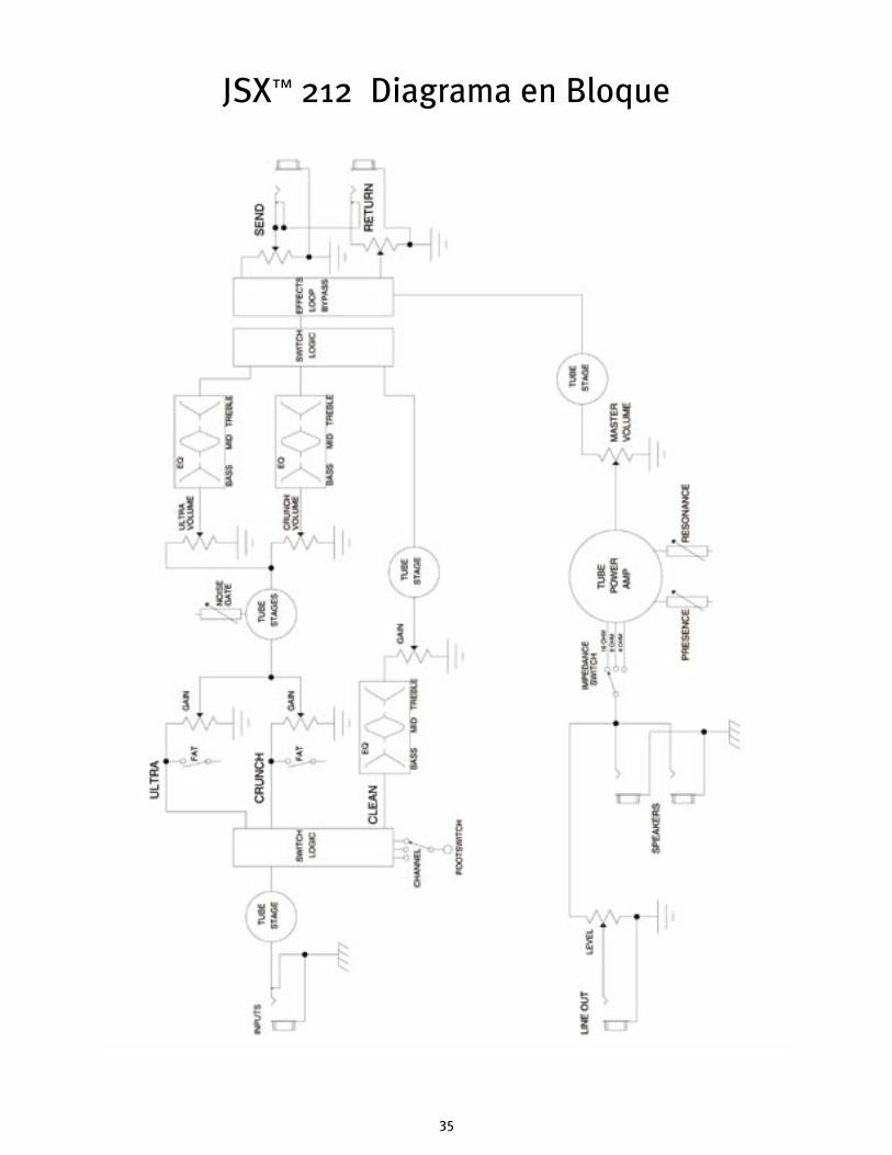
JSX 212 Block Diagram™

16
JSX 212SPECIFICATIONS
Note: For proper ventilation‚ allow 24" clearance from nearest combustible surface.
POWER AMPLIFIER SECTION:
Tubes:Four EL34 tubes with 12AX7 driver Rated Power & Load:130 watts RMS into 16, 8 or 4 ohms
Power @ Clipping:(typically @ 5% THD, 1 kHz, 120 VAC line)130 watts RMS into 16, 8 or 4 ohms
Frequency Response:+/-3 dB, 50 Hz to 20 kHz @ 90 watts RMS into 8 ohms
Hum & Noise:Greater than 76 dB below rated power
Power Consumption:Domestic: 400 watts, 50/60 Hz, 120 V ACExport: 400 watts, 60 Hz, 220-230/240 V AC
PREAMP SECTION:
Tubes:Three 12AX7 tubes
The following specs are measured @ 1 kHz with the controls preset as follows:All EQ controls @ 5Ultra & Crunch Volumes @ 10Master Volume @ 5Resonance and Presence controls @ 5Effects Send @ 0Effects Return @ 10Nominal levels are with Gain @ 5Minimum levels are with Gain @ 10All levels increased by 6 dB if using Low Gain input
Clean Channel:Nominal Input Level: -10 dBV, 300 mV RMSMinimum Input Level: -22 dBV, 80 mV RMSMaximum Input Level: 0 dBV, 1 .0 mV RMS
Crunch Channel:Nominal Input Level: -60 dBV, 1 mV RMSMinimum Input Level: -90 dBV, 0.03 mV RMS
Ultra Channel:Nominal Input Level: -70 dBV, 0.3 mV RMSMinimum Input Level: -90 dBV, 0.03 mV RMS
Effects Send:Load Impedance: 47 k ohms or greater Minimum Output: -10 dBV, 300 mV RMS Maximum Output: 0 dBV, 1 V RMS
Effects Return:Impedance: High Z, 80 k ohms Minimum Input Sensitivity: -10 dBV, 300 mV RMS Maximum Input Sensitivity: 0 dBV, 1 V RMS
Line Output:Load Impedance: 47 k ohms or greater Adjustable Output: +/- 20 dBV, 0.1V RMS-10 V RMS
Remote Footswitch:Special three-button metal footswitch with LED indicators and detachable cord (supplied) selects between three channels and bypasses effects loop
System Hum & Noise @ Nominal Level:(Clean channel - 20 Hz to 20 kHz unweighted)Greater than 74 dB below rated power(Adjustable noise gate circuitry for Ultra & Crunch)
Equalization: Custom bass, mid & treble passive-type EQ on Clean channelSeparate active +/-12 dB bass, mid & treble EQs on Ultra & Crunch channelsFat switches on Ultra & Crunch modifies low frequency responseResonance and presence damping EQ controls in power amp
Dimensions & Weight:20.5" (521 mm) H x 26.5" (673 mm) W x 11" (279 mm) D85.3 lbs. (38.7 kg)
™

17
Felicitaciones en la compra de su amplificador para guitarra
Peavey JSX. JSX es para el guitarrista su sueño hecho realidad – el
amplificador que le impartirá tanto a su sonido como a cualquiera
que sea su estilo de ejecución, una calidad superior. Sólo los
materiales más finos se han utilizado en crear esta máquina tonal
de gran sonido, resistente, digna de giras, y con una apariencia
única. ¡Espero que este amp le guste tanto como a mí!
ESPAÑOL
Características
• Tres Válvulas de preamplificador 12AX7
• Cuatro válvulas de amplificador EL34 alimentados por un 12AX7
• Etapa de potencia convertible para usar válvulas 6L6GC
• Circuito de efectos controlable por pedal con controles independientes de envió y retorno
• Resonancia y controles de amortiguación de presencia.
• Circuito de portón de ruido en canales Ultra y Crunch completamente ajustables.
• Salida de línea con control de nivel
• Interruptor de impedancia de gabinetes (4, 8, o 16 ohmios)
• Interruptores resistentes de encendido standby y canal
• Lámpara clásica indicadora de estatus
• Reverb Accutronics™ a muelles
• Dos altavoces Peavey JSX SP-8 especialmente diseñados
• Interruptor de nivel de potencia High/low
Joe Satriani
™

18
PA N E L F R O N TA L
(1) INTERRUPTOR DE POTENCIA
Este interruptor de dos posiciones aplica corriente a
la unidad. La lámpara de estatus roja (3) se iluminará
cuando el interruptor de encuentre en la posición de
encendido (ON).
(2) INTERRUPTOR DE STANDBY
Este interruptor de dos posiciones permite poner al amplificador en modo STANDBY. En la posición
STANDBY los bulbos se mantienen calientes pero el amplificador no puede ser operado. Cambiar a la
posición de ON pone al amplificador en modo activo.
(3) LÁMPARA DE ESTATUS DE PODER
Este indicador se ilumina cuando el amplificador recibe corriente.
(4) PRESENCIA
Se usa para ajustar precisamente el rango de frecuencias altas de los altavoces a través de la variación
del coeficiente de amortiguación del amplificador para frecuencias altas.
(5) RESONANCIA
Se usa para ajustar precisamente el rango de frecuencias bajas de los altavoces a través de la variación
del coeficiente de amortiguación del amplificador para frecuencias bajas.
(6) VOLUMEN MAESTRO
Este control ajusta el volumen general del amplificador. Una vez que se alcanza el balance entre los
tres canales del amplificador, la salida completa del amplificador puede ser incrementada o reducida al
girar este control. En el sentido de las agujas del reloj el nivel se incrementará; y en sentido contrario
se reducirá.
(7) REVERB MAESTRA
Éste controla el nivel general de reverb.
16
7
5
4 3
2
ADVERTENCIAEL INTERRUPTOR ON/OFF DE ESTE APARATO NO ROMPE AMBOS LADOS DEL CIRCUITO. ENERGÍA PELIGROSA PUEDE ESTAR PRESENTE DENTRO DE LA CAJA CUANDO EL INTERRUPTOR DE ENCENDIDO ESTÉ EN LA POSICIÓN OFF.

19
(8) AGUDOS
Este control, tanto en el canal Crunch como en el Ultra, varÍa la respuesta en frecuencias agudas del
amplificador. Es un control activo (de tipo shelving) y permite aproximadamente 12 dB de recorte o
aumento.
(9) MEDIOS
Este control, tanto en el canal Crunch como en el Ultra, varía la respuesta en frecuencias medias del
amplificador. Es un control activo (de tipo peak/notch) y permite aproximadamente 12 dB de recorte o
aumento.
(10) GRAVESEste control, tanto en el canal Crunch como en el Ultra, varía la respuesta en frecuencias graves del amplificador. Es un control activo (de tipo shelving) y permite aproximadamente 12 dB de recorte o aumento.
(11) VOLUMENEste control, en los tres canales, ajusta el nivel de su respectivo canal.
(12) GANANCIAEste control, tanto en el canal Ultra como Crunch, controla el volumen de entrada del canal. Al girar la perilla en el sentido de las agujas del reloj incrementará la cantidad de distorsión del previo y el sostenido
(13) LEDs DE ACTIVACIÓN DE CANALEstos indicadores indican el canal que está activo. El canal Ultra ilumina el LED rojo, el canal Crunch el amarillo y el canal Limpio el LED verde.
(14) INTERRUPTOR DE EXCESOEstos interruptores de dos posiciones en los canales Ultra y Crunch modifican las respuestas de frecuencia bajas del amplificador y tienen un efecto más notable cuando la guitarra está “limpia”, es decir, con el control de volumen de la guitarra hacia abajo. Este control afecta la tensión del ataque de las notas; el ataque es más “redondeado” cuando el interruptor está en la posición de exceso (FAT).
(15) PORTÓN DE RUIDOEste control está compartido por los canales Ultra y Crunch, y ajusta la efectividad del circuíto del portón de ruido. El ruido se reduce más según el control se gire en dirección de las manecillas del reloj. Evite el usar posiciones altas del portón de ruido cuando use posiciones de ganancia baja; ya que en estas posiciones el decaimiento de la nota se afectará adversamente.
9
8
8
9
10
101112
1112
13
14
1415

20
(16) TREBLEEste control pasivo regula las frecuencias agudas del canal Limpio.
(17) MIDEste control pasivo regula las frecuencias medias del canal Limpio.
(18) BASS
Este control pasivo regula las frecuencias graves del canal Limpio.
(19) ENTRADA DE GANANCIA ALTA
Utilizada por la mayoría de las guitarras eléctricas. Es 6dB más alta que la entrada de Ganancia Baja.
(20) ENTRADA DE GANANCIA BAJAProvista para los instrumentos que tienen salidas extremadamente altas que tienden a sobreimpulsar (distorsionar) la entrada de Ganancia Alta. Si ambas entradas son usadas simultáneamente, los niveles de salida son iguales (ambos son de Ganancia Baja).
(21) INTERRUPTOR DE SELECCIÓN DE CANALEste interruptor de tres posiciones permite la selección entre los tres canales del amplificador. La iluminación de los LEDs (13) indica el canal que está activo. Los canales también se pueden ambiar con pedal. Ver la sección de PEDAL en este manual para una explicación de su uso. El INTERRUPTOR DE SELECCION DE CANAL tiene que estar en la posición Ultra para que el pedal funcione correctamente.
2120
171819 16

21
PA N E L T R A S E R O
(22) NIVEL DE ENVÍO DE EFECTOS
Este control calibrado (0-10) ajusta el nivel de señal que se envía a la unidad de efectos o procesador
externo. La rotación en sentido de las agujas del reloj incrementará la cantidad de señal enviada; la
rotación en dirección contrarreloj reducirá la cantidad. Para la operación más silenciosa, el NIVEL DE
ENVÍO DE EFECTOS debería estar colocado lo más alto posible. En general, los niveles de ENVÍO y
RETORNO deberían estar en proporciones opuestas. Si el NIVEL DE ENVÍO DE EFECTOS está bastante
bajado, el NIVEL DE RETORNO DE EFECTOS (24) debería estar subido para conseguir una ganancia
unitaria.
Nota: El loop de efectos puede además ser usado como un incremento de volumen conmutable
por pedal girando ambos controles más a la derecha.
(23/24) ENVIO DE EFECTOS/RETORNO DE EFECTOS
Estos conectadores mono de 1/4" permiten que la señal sea enviada y regresada de unidades de
efectos externas y/o procesadores. Con cables propiamente aislados mono de 1/4" (TS) tipo phone,
conecta del ENVIO DE EFECTOS a la entrada del procesador externo, y de la salida del procesador al
RETORNO DE EFECTOS. Sólo se deben usar procesadores que no incrementen la ganancia de la señal
en este circuito (chorus, delay, reverb, etc.). Si se usa pedalera el interruptor SELECTOR DE EFECTOS
(39) debe estar oprimido para activar el circuito de efectos. Ver la sección de PEDALERA en este manual
para más detalles de operación.
(25) NIVEL DE RETORNO DE EFECTOS
Este control calibrado (0-10) ajusta el nivel de señal que regresa de la unidad de efectos o procesador
externo. La rotación en sentido de las manecillas del reloj incrementará la cantidad de señal que
regresa; la rotación en dirección contrarreloj reducirá la cantidad. Una vez más, los controles de ENVIO
y RETORNO deben usarse de manera opuesta, con el ENVIO alto y el RETORNO bajo para una operación
más silenciosa.
(26) CONTROL REMOTO
Este conectador DIN de 7 agujas se incluye para la conexión de un pedal de control remoto. El cable
del pedal debe ser conectado antes que el amplificador sea encendido. Ver la sección de PEDALERA en
este manual para más detalles de operación.
(27) TERMINALES DE PRUEBA DE BIAS
Estas terminales se incluyen para medir el bias de las válvulas del amplificador. Una perilla detrás
de la parrilla trasera permite su ajuste. El ajuste del bias sólo debe llevarse a cabo por un técnico
cualificado.
CAUTION
FUSE FUSE
26
22
23
24
25
27
22
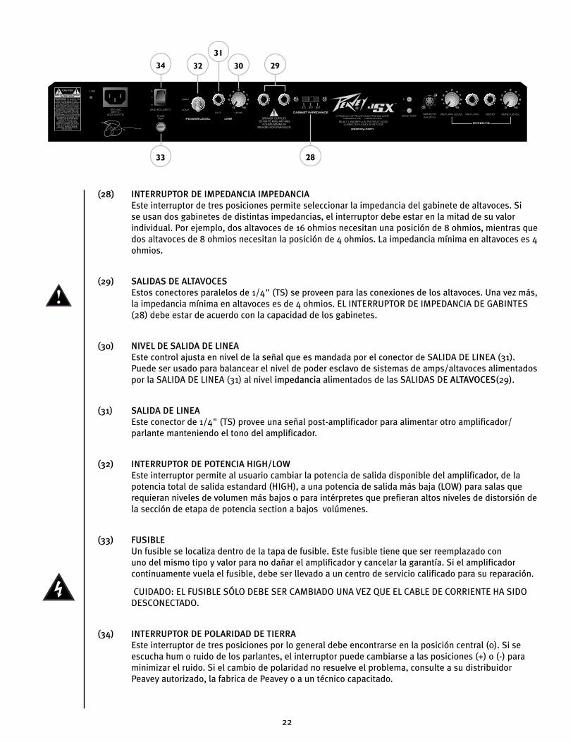
(28) INTERRUPTOR DE IMPEDANCIA IMPEDANCIAEste interruptor de tres posiciones permite seleccionar la impedancia del gabinete de altavoces. Si se usan dos gabinetes de distintas impedancias, el interruptor debe estar en la mitad de su valor individual. Por ejemplo, dos altavoces de 16 ohmios necesitan una posición de 8 ohmios, mientras que dos altavoces de 8 ohmios necesitan la posición de 4 ohmios. La impedancia mínima en altavoces es 4 ohmios.
(29) SALIDAS DE ALTAVOCESEstos conectores paralelos de 1/4" (TS) se proveen para las conexiones de los altavoces. Una vez más, la impedancia mínima en altavoces es de 4 ohmios. EL INTERRUPTOR DE IMPEDANCIA DE GABINTES (28) debe estar de acuerdo con la capacidad de los gabinetes.
(30) NIVEL DE SALIDA DE LINEAEste control ajusta en nivel de la señal que es mandada por el conector de SALIDA DE LINEA (31). Puede ser usado para balancear el nivel de poder esclavo de sistemas de amps/altavoces alimentados por la SALIDA DE LINEA (31) al nivel impedancia alimentados de las SALIDAS DE ALTAVOCES(29).
(31) SALIDA DE LINEAEste conector de 1/4" (TS) provee una señal post-amplificador para alimentar otro amplificador/parlante manteniendo el tono del amplificador.
(32) INTERRUPTOR DE POTENCIA HIGH/LOW Este interruptor permite al usuario cambiar la potencia de salida disponible del amplificador, de la potencia total de salida estandard (HIGH), a una potencia de salida más baja (LOW) para salas que requieran niveles de volumen más bajos o para intérpretes que prefieran altos niveles de distorsión de la sección de etapa de potencia section a bajos volúmenes.
(33) FUSIBLEUn fusible se localiza dentro de la tapa de fusible. Este fusible tiene que ser reemplazado con uno del mismo tipo y valor para no dañar el amplificador y cancelar la garantía. Si el amplificador continuamente vuela el fusible, debe ser llevado a un centro de servicio calificado para su reparación.
CUIDADO: EL FUSIBLE SÓLO DEBE SER CAMBIADO UNA VEZ QUE EL CABLE DE CORRIENTE HA SIDO DESCONECTADO.
(34) INTERRUPTOR DE POLARIDAD DE TIERRAEste interruptor de tres posiciones por lo general debe encontrarse en la posición central (0). Si se escucha hum o ruido de los parlantes, el interruptor puede cambiarse a las posiciones (+) o (-) para minimizar el ruido. Si el cambio de polaridad no resuelve el problema, consulte a su distribuidor Peavey autorizado, la fabrica de Peavey o a un técnico capacitado.
CAUTION
FUSE FUSE
33 28
2930
31
3234
23
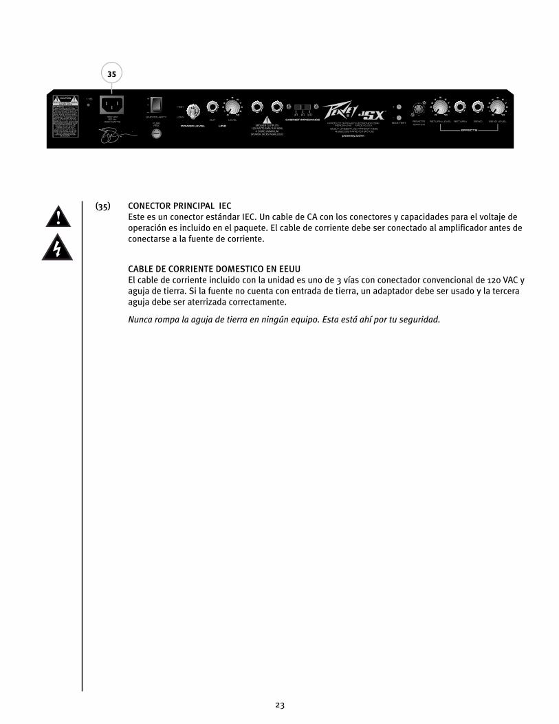
(35) CONECTOR PRINCIPAL IEC Este es un conector estándar IEC. Un cable de CA con los conectores y capacidades para el voltaje de operación es incluido en el paquete. El cable de corriente debe ser conectado al amplificador antes de conectarse a la fuente de corriente.
CABLE DE CORRIENTE DOMESTICO EN EEUUEl cable de corriente incluido con la unidad es uno de 3 vías con conectador convencional de 120 VAC y aguja de tierra. Si la fuente no cuenta con entrada de tierra, un adaptador debe ser usado y la tercera aguja debe ser aterrizada correctamente.
Nunca rompa la aguja de tierra en ningún equipo. Esta está ahí por tu seguridad.
CAUTION
FUSE FUSE
35
24
P E D A L
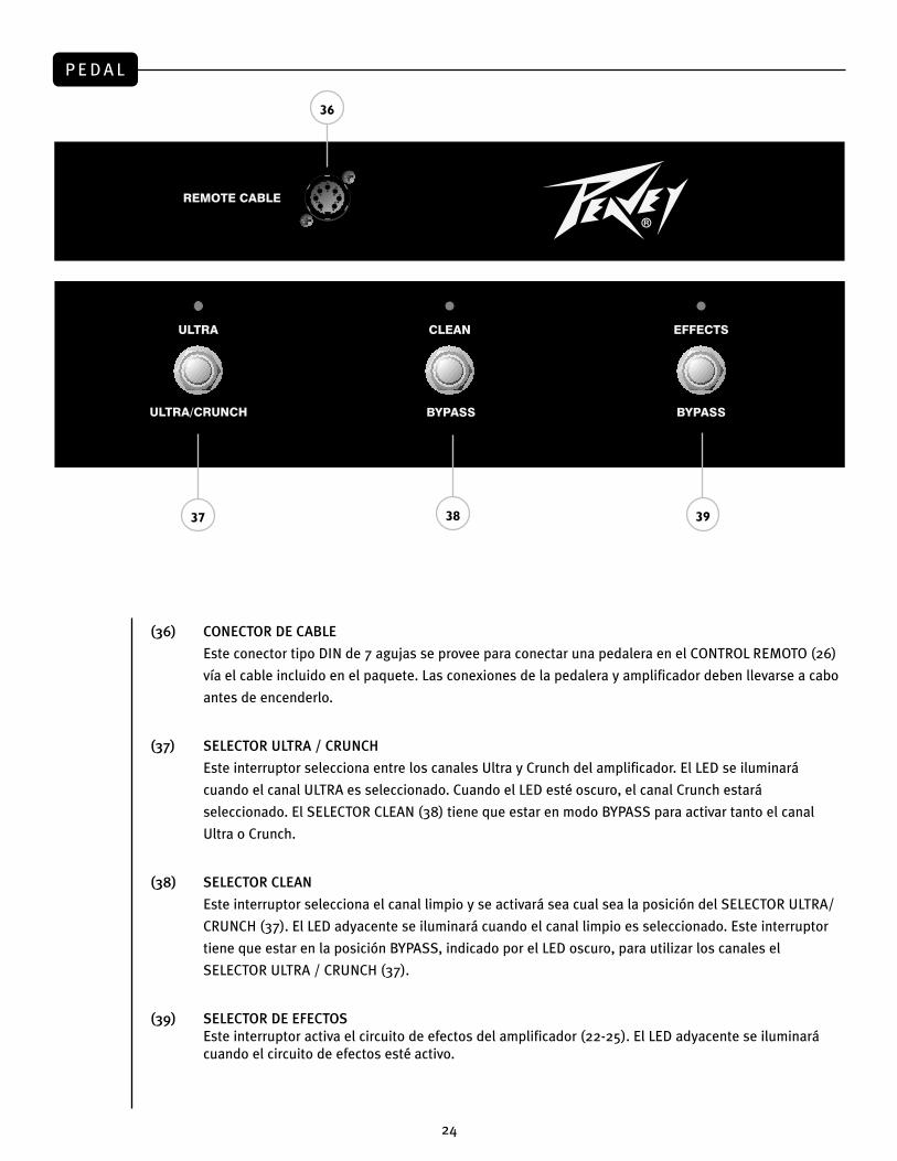
(36) CONECTOR DE CABLE
Este conector tipo DIN de 7 agujas se provee para conectar una pedalera en el CONTROL REMOTO (26)
vía el cable incluido en el paquete. Las conexiones de la pedalera y amplificador deben llevarse a cabo
antes de encenderlo.
(37) SELECTOR ULTRA / CRUNCH
Este interruptor selecciona entre los canales Ultra y Crunch del amplificador. El LED se iluminará
cuando el canal ULTRA es seleccionado. Cuando el LED esté oscuro, el canal Crunch estará
seleccionado. El SELECTOR CLEAN (38) tiene que estar en modo BYPASS para activar tanto el canal
Ultra o Crunch.
(38) SELECTOR CLEAN
Este interruptor selecciona el canal limpio y se activará sea cual sea la posición del SELECTOR ULTRA/
CRUNCH (37). El LED adyacente se iluminará cuando el canal limpio es seleccionado. Este interruptor
tiene que estar en la posición BYPASS, indicado por el LED oscuro, para utilizar los canales el
SELECTOR ULTRA / CRUNCH (37).
(39) SELECTOR DE EFECTOSEste interruptor activa el circuito de efectos del amplificador (22-25). El LED adyacente se iluminará cuando el circuito de efectos esté activo.
37 39
36
38

25
JSX™ 212 Diagrama en Bloque

26
JSX™ 212ESPECIFICACIONES
Note: For proper ventilation‚ allow 24" clearance from nearest combustible surface.
POWER AMPLIFIER SECTION:
Bulbos:Cuatro tubos EL34 con 12AX7 impulsor Potencia Nominal & Carga:130 Wats (Vatios) RMS a 16, 8, ó 4 ohmios
Capacidad @ Clipping:Potencial @ Mutilación de Señales(típicamente @ 5% THD, 1 kHz, línea 120 VAC )130 Wats (Vatios) RMS a 16, 8, ó 4 ohmios
Respuesta de frecuencias:+/- 3 dB, 50 Hz a 20 kHz @ 90 Wats (Vatios) RMS a 8 ohmios
Hum y ruido:Mayor de 76 dB bajo potencia nominal
Consumo de Potencia:Doméstico: 400 Wats (Vatios), 50/60 Hz, 120 V ACExportación: 400 Wats (Vatios), 60 Hz, 220-230/240 V AC
PREAMP SECTION:
Válvulas:Tres tubos 12AX7
Las siguientes especificaciones son medidas @ 1 kHz con los controles preajustados como sigue:Todos los controles EQ @ 5Volúmenes de los Canales Ultra & Crunch @ 10Volumen Maestro @ 5Resonancia y controles de Presencia @ 5Envío de Efectos @ 0Devolución de Efectos @ 10Niveles nominales están con Ganancia @ 5Niveles mínimos están con Ganancia @ 10Todos los niveles aumentan por 6 dB si usanEntrada de Baja Ganancia
Canales limpiosNivel Nominal de Entrada : -10 dBV, 300 m V RMSNivel Mínimo de Entrada: -22 dBV, 80 m V RMSNivel Máximo de Entrada: 0 dBV, 1.0 m V RMS
Canal Crunch:Nivel Nominal de Entrada: -60 dBV, 1 m V RMSNivel Mínimo de Entrada: -90 dBV, 0.03 m V RMS
Canal Ultra:Nivel Nominal de Entrada: -70 dBV, 0.3 m V RMSNivel Mínimo de Entrada: -90 dBV, 0.3 m V RMS
Envío de Efectos:Carga de Impedancia: 47 k ohmios o mayor Salida Mínima -10 dBV, 300 mV RMS Salida Máxima 0 dBV, 1 V RMS
Devolución de Efectos:Impedancia: Alta Z, 80 k ohmios Entrada de Mínima Sensitividad: -10 dBV, 300 mV RMS Entrada de Máxima Sensitividad: 0 dBV, 1 V RMS
Línea de Salida:Carga de Impedancia: 47 k ohmios o mayor Salida Ajustable: +/- 20 dBV, 0.1V RMS-10 V RMS
Pedal de Interruptor Remoto:Pedal especial de metal de tres botones con indicadores LED y cable removible (incluído) para seleccionar entre tres canales y sobrepasar efectos circulares.
Zumbido (Hum) & Ruido de Sistema @ Niveles Nominales:(Canal limpio – 20 Hz a 20 kHz descompensado)Mayor que 74 dB bajo potencia nominal(Circuito de Portal de Ruido Ajustable para Ultra & Crunch)
Ecualización:Ecualización a la medida para graves, medios, y agudos tipo pasivo EQ en canal limpio Separado activo +/-12 dB graves, medios, y agudos EQ en canales Ultra & Crunch Interruptores de exceso en Ultra & Crunch para modificar la respuesta de frecuencia baja Resonancia y controles de ecualización de amortiguación de presencia en amplificador de potencia
Dimensiones y Peso:20.5" (521 mm) H x 26.5" (673 mm) W x 11" (279 mm) D85.3 lbs. (38.7 kg)
27
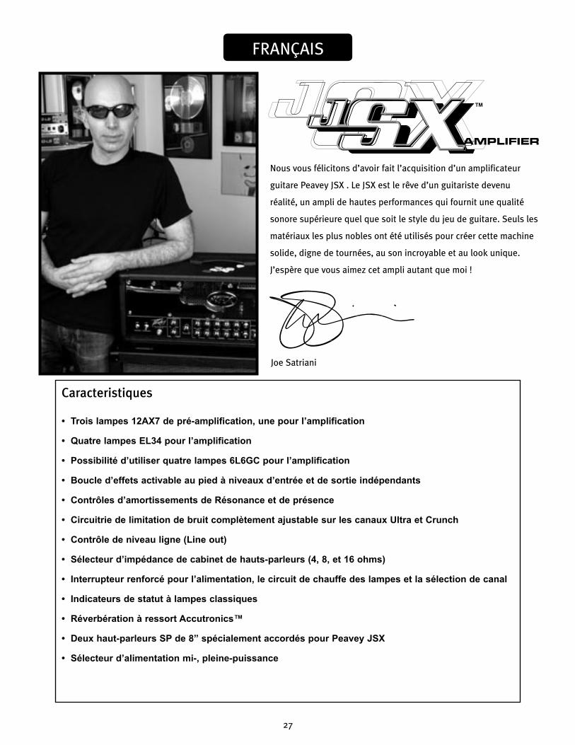
Nous vous félicitons d’avoir fait l’acquisition d’un amplificateur
guitare Peavey JSX . Le JSX est le rêve d’un guitariste devenu
réalité, un ampli de hautes performances qui fournit une qualité
sonore supérieure quel que soit le style du jeu de guitare. Seuls les
matériaux les plus nobles ont été utilisés pour créer cette machine
solide, digne de tournées, au son incroyable et au look unique.
J’espère que vous aimez cet ampli autant que moi !
FRANÇAIS
Caracteristiques
• Trois lampes 12AX7 de pré-amplification, une pour l’amplification
• Quatre lampes EL34 pour l’amplification
• Possibilité d’utiliser quatre lampes 6L6GC pour l’amplification
• Boucle d’effets activable au pied à niveaux d’entrée et de sortie indépendants
• Contrôles d’amortissements de Résonance et de présence
• Circuitrie de limitation de bruit complètement ajustable sur les canaux Ultra et Crunch
• Contrôle de niveau ligne (Line out)
• Sélecteur d’impédance de cabinet de hauts-parleurs (4, 8, et 16 ohms)
• Interrupteur renforcé pour l’alimentation, le circuit de chauffe des lampes et la sélection de canal
• Indicateurs de statut à lampes classiques
• Réverbération à ressort Accutronics™
• Deux haut-parleurs SP de 8” spécialement accordés pour Peavey JSX
• Sélecteur d’alimentation mi-, pleine-puissance
Joe Satriani
™

28
PA N N E A U A V A N T
(1) SELECTEUR D’ALIMENTATIONCet interrupteur 2-positions contrôle l’alimentation électrique pour votre unité. Une lampe de statut (3) s’illumine lorsque l’unité est sous tension.
2) SELECTEUR DE CIRCUIT DE CHAUFFE (STANDBY)Cet interrupteur 2-positions permet à votre unité d’alimenter les lampes sans les rendre opérationnelles (aucun signal en sortie). En position STANDBY, les lampes sont alimentées pour leur permettre de monter (ou de rester) en température mais votre unité n’est pas opérationelle. Passez en position ON pour mettre votre unité en mode de fonctionnement.
(3) LAMPE DE STATUT
Cette indicateur s’illumine lorsque votre unité est mise sous tension.
(4) PRESENCEUtilisé pour accorder avec finesse la gamme des hautes fréquences du haut-parleur en variant le facteur d’amortissement de l’amplificateur sur les hautes fréquences.
(5) RESONANCEUtilisé pour accorder avec finesse la gamme des basses fréquences du haut-parleur en variant le facteur d’amortissement de l’ampli sur les basses fréquences.
(6) MASTER VOLUMECe contrôle permet de régler le niveau de sortie général de votre unité. Un fois que la balance entre les différents volumes des différents canaux vous satisfait, vous pouvez utilisez ce contrôle pour monter ou descendre le niveau général. Une rotation horaire augmente le volume, une rotation anti-horaire diminue ce dernier.
(7) MASTER REVERB
Ce contrôle ajuste le niveau général de réverbération
16
7
5
4 3
2
ATTENTIONL'INTERRUPTEUR D'ALIMENTATION NE COUPE PAS CELLE-CI AUX DEUX BORNES ET DE L'ENERGIE ELECTRIQUE PEUT ETRE PRESENTE DANS CERTAINS COMPOSANTS APRES LA MISE HORS-TENSION.

29
(8) TREBLECe contrôle, sur les canaux Ultra et Crunch, permet de modifier la réponse en hautes fréquences de votre unité sur ces canaux. Ce contrôle est actif et vous permet jusqu’à 12 dB de modification (augmentation/coupure).
(9) MEDIUMS Ce contrôle, sur les canaux Ultra et Crunch, permet de modifier la réponse en fréquences mediums de votre unité sur ces canaux. Ce contrôle est actif et vous permet jusqu’à 12 dB de modification (augmentation/coupure).
(10) BASS Ce contrôle, sur les canaux Ultra et Crunch, permet de modifier la réponse en basses fréquences de votre unité sur ces canaux. Ce contrôle est actif et vous permet jusqu’à 12 dB de modification (augmentation/coupure).
(11) VOLUMECe contrôle, sur chacun des canaux, permet de régler le niveau du canal concerné.
(12) GAINCe contrôle, sur les canaux Ultra et Crunch, vous permet de déterminer le niveau du signal d’entrée dans le canal correspondant. Tournez ce contrôle horairement pour augmenter le niveau de saturation.
(13) LEDS D’INDICATION DE CANAL ACTIFCes Leds vous indique quel canal est actif. Le canal Ultra active la Led rouge, le canal Crunch active la Led jaune et le canal clair la Led verte.
(14) FAT SWITCH (Sélecteur FAT)Ces sélecteurs à deux positions sur les canaux Ultra et Crunch modifient la réponse dans les graves de l’amplificateur et ont un effet particulièrement notable quand le signal de la guitare est étouffé, par exemple lorsque le contrôle de volume est proche de la position minimum. Ce contrôle affecte l’étroitesse de l’attaque des notes; l’attaque est plus molle lorsque le sélecteur est en position « FAT ».
(15) NOISE GATE (Limitateur de bruit)Ce contrôle est partagé par les canaux Ultra et Crunch et ajuste l’efficacité de la circuitrie limitant le bruit. Le bruit est réduit encore davantage si on tourne le contrôle dans le sens horaire. Evitez d’utiliser des réglages élevés de limitation de bruit quand vous utilisez des réglages plus faibles de gain, puisque à ces réglages, l’amortissement de la note sera compromis.
9
8
8
9
10
101112
1112
13
14
1415

30
(16) TREBLECe contrôle passif vous permet de filtrer les fréquences aigues du canal clair.
(17) MIDCe contrôle passif vous permet de filtrer les fréquences medium du canal clair.
(18) BASSCe contrôle passif vous permet de filtrer les fréquences graves du canal clair.
(19) HIGH GAIN INPUT (Entrée de gain élevé)A Utiliser avec la plupart des guitares électroniques, sa sensibilité est de 6 dB supérieure à l’entrée de de faible gain de 6 dB.
(20) LOW GAIN INPUT (Entrée de faible gain)Fournie pour les instruments qui possèdent de hauts rendements de sortie susceptibles de saturer le signal à l’entrée de votre unité. Si les deux entrées sont utilisées simultanément, les sensibilités des deux entrées seront identiques et de faible gain.
(21) SELECTEUR DE CANALCe selecteur 3-positions vous permet de sélectionner un des 3 canaux de votre unité. Les Leds d’indication de canal actif (13) vous signale lequel est actuellement actif. La sélection de canal peut également être controlée par le pédalier (fourni). Reportez-vous à la section PEDALIER de ce manuel pour plus d’informations sur ce sujet. Le sélecteur de canal doit être en position Ultra pour que le pédalier fonctionne correctement.
2120
171819 16

31
PA N N E A U A R R I È R E
(22) CONTROLE DE NIVEAU D’ENVOI D’EFFETS (EFFECTS SEND LEVEL)Ce contrôle calibré (0 –10) détermine le niveau du signal envoyé par la sortie EFFECTS SEND à une unité externe d’effets ou autre (Pédale de volume,...). Le tourner horairement augmentera ce niveau et vice-versa. Pour un niveau de bruit le plus faible possible le bouton EFFECTS SEND LEVEL doit être positionné au niveau maximum toléré par l’unité d’effets externe. Généralement les niveaux d’envoi et de retour doivent êtres positionnés de manière opposée.
Si le réglage d’envoi est bas le niveau de retour devra être élevé pour atteindre un gain de sortie suffisant.
Note: La boucle d’effet peut également comme un renfort de volume contrôlable au pied en
augmentant au maximum les deux boutons.
(23/24) BOUCLE D’EFFETS (EFFECTS SEND / EFFECTS RETURN) Ces jacks 1/4" mono (TS) permettent de connecter une unité externe d’effets ou autres (Pédale de volume,...). En utilisant des cables blindés mono (les plus courts possibles), connectez le EFFECT SEND(17) à l’entrée de votre unité externe et sa sortie au EFFECTS RETURN (18). Si le pédalier est utilisé, le sélecteur EFFECTS SELECTOR (39) doit être en position relachée pour activer la boucle d’effets. Reportez-vous à la section PEDALIER de ce manuel pour plus d’informations.
(25) CONTROLE DE NIVEAU DE RETOUR D’EFFETS (EFFECTS RETURN LEVEL)Ce contrôle calibré (0 –10) détermine le niveau du signal retourné par votre unité externe d’effets ou autre (Pédale de volume,...). Le tourner horairement augmentera ce niveau et vice-versa. De même, les niveaux d’envoi et de retour doivent êtres proportionés de manière opposée. Egalement, pour un niveau de bruit le plus faible possible le bouton EFFECTS SEND LEVEL doit être positionné au niveau maximum toléré par l’unité d’effets externe, permettant de positionner le contrôle EFFECTS RETURN LEVEL au minimum.
(26) REMOTE SWITCH (PEDALIER)Ce connecteur 7-pins DIN vous permet de connecter le pédalier (fourni) à votre unité. Cette connection doit être effectuée avant la mise sous tension de l’appareil. Reportez-vous à la section PEDALIER de ce manuel pour plus d’informations.
(27) BIAS TEST TERMINALSCes connecteurs permettent d’obtenir la valeur de Bias de votre ampli de puissance. Un contrôle situé derrière la grille permet de le modifier si besoin. Seul un technicien qualifié peut correctement régler ce contrôle.
CAUTION
FUSE FUSE
26
22
23
24
25
27

32
(28) SELECTEUR D’IMPEDANCE D’ENCEINTECe sélecteur 3-positions vous permet d’accorder le transformateur de sortie de votre unité à la charge totale de vos enceintes. Si une seule enceinte est utilisée, positionnez le sélecteur sur l’impédance de celle-ci. Si 2 enceintes sont utilisées (identiques), positionnez le sélecteur sur la moitié de l’impédance d’une de vos enceintes. Par exemple, 2 enceintes de 8 ohms chacunes nécessitent la position 4 ohms,...
La charge de travail minimum de votre unité est 4 ohms.
(29) SORTIES HAUTS-PARLEURS
Ces jack 1/4" mono (TS) sont montés en parallèles et vous permettent de connecter vos enceintes à
votre unité. Le sélecteur d’impédance (27) doit ëtre positionné sur la position donnée par le nombre et
l’impédance des enceintes que vous comptez utiliser. La charge de travail minimum de votre unité est
4 ohms
(30) CONTROLE DE SORTIE LIGNE (LINE LEVEL)
Ce potentiomètre permet de controler le niveau du signal à la sortie ligne de votre unité (31). Ajustez
ce niveau en fonction de la sensibilité de l’appareil à réception (Mixer, Amplificateur additionnel,...).
(31) SORTIE LIGNE (LINE OUT)
Ce jack 1/4" mono (TS) permet d’envoyer un signal post-ampli vers un autre appareil (Mixer,
Amplificateur additionnel,...) pour augmenter le volume sonore sans changer la tonalité de votre unité.
(32) SELECTEUR MI-/PLEINE-PUISSANCE
Ce sélecteur permet de changer la puissance de sortie disponible de l’amplificateur de sa puissance
d’origine (HIGH) pour une puissance et un volume réduits dans le cas ou l’utilisateur préfère utiliser
au maximum la puissance des lampes pour un haut niveau de distortion un faible niveau sonore..
(33) FUSIBLE
Un fusible est situé dans le capuchon dévissable. Il peut être remplacé par un autre fusible de mêmes
type et valeur pour éviter tout dommage à votre unité et la validité de sa garantie. Si votre unité fait
régulièrement sauter ce fusible, faites-la vérifier par un technicien qualifié.
ATTENTION: LE CABLE SECTEUR DOIT ETRE DECONNECTE AVANT TOUTE OPERATION SUR LE FUSIBLE.
(34) SELECTEUR DE VALEUR D’ALIMENTATION
Placez ce sélecteur en accordance avec l’alimentation de votre localité.
CAUTION
FUSE FUSE
33 28
2930
31
3234

33
(35) CONNECTEUR IEC
Ceci est la prise d’alimentation à la norme IEC. Vous trouverez dans le carton de votre unité un
câble d’alimentation approprié au voltage nécésaire et a cette prise. Ce câble doit être connecté à
l’amplificateur avant d’être branché à l’alimentation.
NOTE POUR LES ROYAUMES UNIS:
Si les couleurs de connecteurs du cable d’alimentation ne correspond pas au guide de la prise secteur,
procédez comme suit: (1) Le connecteur vert et jaune doit être connectrer au terminal noté E, indiquant
la prise de terre ou correspondant aux couleurs verte ou verte et jaune du guide. (2) Le connecteur
Bleu doit être connectrer au terminal noté N, correspondnat à la couleur noire du guide. (3) Le
connecteur marron doit être connectrer au terminal noté L, correspondant à la couleur rouge du guide.
CAUTION
FUSE FUSE
35

34
P É D A L I E R
(36) CONNECTEUR CABLE DIN
Ce connecteurs 7-pins DIN vous permet de connecter le pédalier à votre unité via un cable 7-pins DIN
(fourni). Le branchement du pédalier doit se faire avant la mise sous tension de votre unité.
(37) SELECTEUR ULTRA / CRUNCH
Ce sélecteur vous permet de choisir entre les canaux Ultra et Crunch de votre unité. La Led s’illuminera
quand le canal Ultra est actif, et restera éteinte pour indiquer la sélection du canal Crunch. Le sélecteur
CLEAN (38) doit être sur BYPASS pour pouvoir activer les canaux Crunch et Ultra.
(38) SELECTEUR DE CANAL CLAIR (CLEAN)
Ce sélecteur vous permet d’activer le canal clair, quelle que soit la position du sélecteur Ultra/
Crunch(37). La Led correspondante s’illuminera quand le canal clair est sélectionné. Ce sélecteur doit
être en position BYPASS pour activer les autres canaux Crunch et Ultra.
(39) SELECTEUR D’EFFETS
Ce sélecteur vous permet d’activer la boucle d’effets de votre unité (22 – 25). La Led correspondante
s’illuminera quand la boucle est active.
37 39
36
38
35
JSX™ 212 Diagrama en Bloque

36
JSX™212SPECIFICATIONS
Note: For proper ventilation‚ allow 24" clearance from nearest combustible surface.
SECTION AMPLIFICATEUR DE PUISSANCELampes:Quatre lampes EL34 combinées à des 12AX7
Puissance Nominale et Charge:130 watts RMS sous16, 8 ou 4 ohms.
Puissance en crête:(typiquement à 5% THD, 1 kHz, 120 V en courant alternatif )130 watts RMS sous 16, 8 ou 4 ohms.
Réponse en fréquence: +/- 3 dB, de 50 Hz à 20 kHz à 90 watts RMS sous 8 ohms.
Ronflement et Bruit:Supérieur à 76 dB en dessous de la puissance nominale.
Consommation Electrique:USA : 400 watts, 50/60 Hz, 120 V Courant alternatif.Export : 400 watts, 60 Hz, 220-230/240 V courant alternatif.
SECTION PREAMPLILampes:Trois lampes 12AX7
Les spécifications suivantes ont été mesurées à 1 kHz avec les contrôles préréglés comme ci-dessous :
Tous les contrôles EQ sur 5Les volumes de Ultra & Crunch sur 10Le Master Volume sur 5Les contrôles de Resonance et de Presence sur 5Effects Send sur 0Effects Return sur 10Les niveaux nominaux sont avec un gain sur 5Les niveaux minimums sont avec un gain sur 10Tous les niveaux augmentés de 6 dB si utilisés avecLow Gain input (entrée de faible gain)
Le canal Clean: Niveau nominal d’entrée : -10 dBV, 300 mV RMSNiveau minimum d’entrée : -22 dBV, 80 mV RMSNiveau maximum d’entrée : 0 dBv, 10 mV RMS
Canal Crunch:Niveau nominal d’entrée : -60 dBV, 1 mV RMSNiveau minimum d’entrée : -90 dBV, 0.03 mV RMS
Canal Ultra:Niveau nominal d’entrée : -70 dBV, 0.3 mV RMSNiveau minimum d’entrée : -90 dBV, 0.03 mV RMS
Effects Send:Charge d’impédance : 47 k ohms ou plus Rendement minimum : -10 dBV, 300 mV RMS Rendement maximum : 0 dBV, 1 V RMS
Effects Return:Impédance : High Z, 80 k ohms Sensibilité minimum en entrée : -10 dBV, 300 mV RMS Sensibilité maximum en entrée : 0 dBV, 1 V RMS
Sortie Ligne:Charge d’impédance : 47 k ohms ou plus Sortie ajustable: +/-20 dBV, 0.1 V RMS-10 V RLS
Pédale de contrôle:La pédale spéciale de contrôle à trois boutons en métal avec des témoins lumineux LED et un cordon détachable (inclus) permet de sélectionner les trois canaux et la boucle d’effets bypasses.
Système Ronflement et Bruit au niveau nominal: (Canal Clean de –20 Hz à 20 kHz non pondéré)Supérieur à 74 dB en dessous de la puissance nominale(Circuitrie de limitation de bruit ajustable four Ultra & Crunch)
Egalisation:EQ personalisable de type passif pour les basses, les médiums et les aigus sur le canal Clean. EQs séparés actives +/-12 dB pour les basses, les médiums et les aigus sur les canaux Ultra et Crunch. Sélecteurs Fat sur Ultra & Crunch modifient la réponse en fréquence dans les basses. Contrôles EQ d’amortissement pour la Résonance et la Présence dans l’ampli de puissance.
Dimensions et Poids: 20.5" (521 mm) H x 26.5" (673 mm) W x 11" (279 mm) D85.3 lbs. (38.7 kg)

37
Herzlichen Glückwunsch! Sie haben gerade einen Peavey JSX
Gitarrenverstärker erworben. Mit dem JSX wird ein Gitarristentraum
wahr, denn der Verstärker liefert hervorragende Soundqualität
und viel Leistung für jede Art von Gitarrenspiel. Für den Bau
dieses robusten Verstärkers, der sich durch tollen Klang und ein
einzigartiges Design auszeichnet und der jede Tour problemlos
mitmacht, wurden nur die besten Materialien verwendet. Ich hoffe,
Ihnen gefällt dieser Verstärker genauso gut wie mir!
DEUTSCH
Merkmale• Drei 12AX7-Vorstufenröhren
• Vier EL34 Endstufenröhren, angesteuert via 12AX7
• Endstufe für Betrieb mit vier 6L6GC-Röhren konvertierbar
• Fußschaltbarer Effektweg mit separaten Send- und Return-Reglern
• Resonance- und Presence-Damping-Regler
• Vollständig regulierbare Noise-Gate-Schaltung an Ultra- und Crunch-Kanal
• Line-Ausgang mit Pegelregler
• Impedanzwahlschalter für die Lautsprecherausgänge (4, 8 oder 16 ohm)
• Robuste Schalter (Toggle-Switches) für Power, Standby und Kanalanwahl
• Betriebsanzeigelampe im klassischen Stil
• Accutronics™-Federhall
• Zwei speziell abgestimmte Peavey JSX SP-8-Lautsprecher
• High/Low-Leistungspegelschalter
Joe Satriani
™

38
V O R D E R S E I T E
(1) POWERMit diesem Knebelschalter schalten Sie den Strom für das Gerät ein oder aus. In der Schalterstellung ON leuchtet die rote Statusanzeige (3).
(2) STANDBYMit diesem Knebelschalter schalten Sie den Verstärker in den STANDBY-Betrieb, d.h. die Betriebstemperatur der Röhren bleibt erhalten, der Verstärker als solches ist jedoch inaktiv. Möchten Sie in den aktiven Betrieb wechseln, schalten Sie diesen Schalter in die ON-Position.
(3) POWER-ANZEIGEZur Feinabstimmung des Hochfrequenzbereichs der Lautsprecherbox wird mit diesem Regler der Dämpfungsfaktor des Verstärkers bei hohen Frequenzen verändert.
(4) PRESENCEZur Feinabstimmung des Hochfrequenzbereichs der Lautsprecherbox wird mit diesem Regler der Dämpfungsfaktor des Verstärkers bei hohen Frequenzen verändert.
(5) RESONANCEZur Feinabstimmung des Niederfrequenzbereichs der Lautsprecherbox wird mit diesem Regler der Dämpfungsfaktor des Verstärkers bei tiefen Frequenzen verändert.
(6) MASTER VOLUMEMit diesem Regler wird der Gesamtlautstärkepegel des Verstärkers festgelegt. Ist der gewünschte Abgleich zwischen den drei Kanälen des Verstärkers erzielt, kann der Ausgangspegel des Geräts durch Drehen dieses Reglers insgesamt erhöht oder gesenkt werden. Durch Drehen im Uhrzeigersinn wird der Pegel erhöht, durch Drehen im entgegengesetzten Uhrzeigersinn wird er gesenkt.
(7) MASTER REVERB
Mit diesem Regler wird die Gesamtstärke des Reverb eingestellt.
16
7
5
4 3
2
WARNUNGDER AN/AUS SCHALTER IN DIESEM GERÄT UNTERBRICHT NICHT BEIDE SEITEN DES NETZES. AUCH WENN DER SCHALTER AUF "AUS" STEHT KANN IM INNERN DES GERÄTES IMMER NOCH GEFÄHRLICHE ELEKTRISCHE ENERGIEN VORHANDEN SEIN.

39
(8) TREBLEMit diesem Regler wird bei den Kanälen Ultra und Crunch das Ansprechen des Verstärkers bei hohen Frequenzen eingestellt. Dieser aktive Klangregler (stufenlos verstellbar) ermöglicht ein Anheben oder Absenken um etwa 12 dB.
(9) MID Mit diesem Regler wird bei den Kanälen Ultra und Crunch das Ansprechen des Verstärkers bei mittleren Frequenzen eingestellt. Dieser aktive Klangregler (Spitze/Kerbe) ermöglicht ein Anheben oder Absenken um etwa 12 dB.
(10) BASS Mit diesem Regler wird bei den Kanälen Ultra und Crunch das Ansprechen des Verstärkers bei tiefen Frequenzen eingestellt. Dieser aktive Klangregler (stufenlos verstellbar) ermöglicht ein Anheben oder Absenken um etwa 12 dB.
(11) VOLUMEMit diesem Regler wird – bei allen drei Kanälen – der Gesamtpegel des jeweiligen Kanals festgelegt.
(12) GAINMit diesem Regler wird bei den Kanälen Ultra und Crunch der Eingangslautstärkepegel des jeweiligen Kanals eingestellt. Durch Drehen dieses Reglers im Uhrzeigersinn wird der Grad an Verzerrung und Sustain des Vorverstärkers erhöht.
(13) CHANNEL-LEDsDiese LEDs dienen der Anzeige des jeweils aktiven Kanals. Rot steht für den Ultra-Modus, gelb für den Crunch-Modus und grün für den Clean-Modus.
(14) FAT-SCHALTERDiese zweistufigen Kipphebelschalter an den Kanälen Ultra und Crunch verändern das Ansprechen des Verstärkers bei niedrigen Frequenzen. Am stärksten zeigt sich diese Wirkung, wenn die Gitarre „clean“ gespielt wird, d.h. ihr Lautstärkeregler herunter gedreht wird. Mit diesem Regler wird die Ansprechgeschwindigkeit der Töne beeinflusst. Steht der Schalter auf Position „FAT“, sprechen sie langsamer an.
(15) NOISE GATEDieser Regler ist für Ultra- und Crunch-Kanal vorhanden und dient zum Einstellen der Effektivität der Noise-Gate-Schaltung. Je weiter der Regler im Uhrzeigersinn gedreht wird, desto mehr wird das Rauschen verringert. Hohe Einstellungen der Noise-Gate-Schaltung sollten bei niedrigen Gain-Einstellungen vermieden werden, da bei diesen Einstellungen das Abklingen des Tons beeinträchtigt wird.
9
8
8
9
10
101112
1112
13
14
1415
40
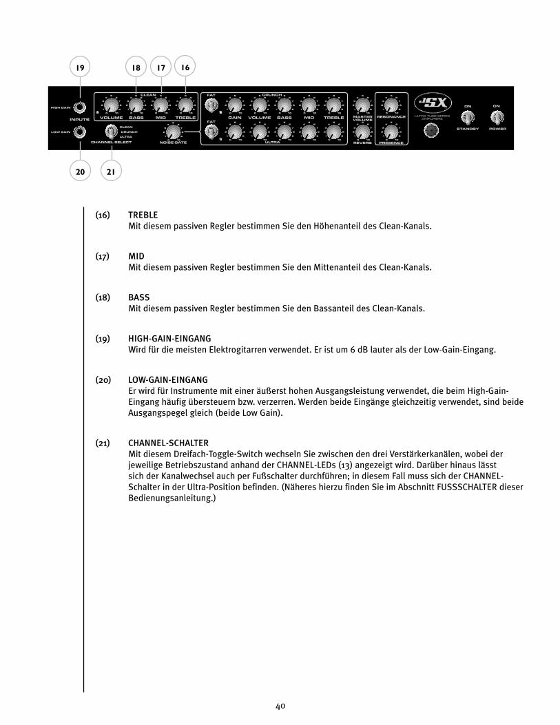
(16) TREBLEMit diesem passiven Regler bestimmen Sie den Höhenanteil des Clean-Kanals.
(17) MIDMit diesem passiven Regler bestimmen Sie den Mittenanteil des Clean-Kanals.
(18) BASSMit diesem passiven Regler bestimmen Sie den Bassanteil des Clean-Kanals.
(19) HIGH-GAIN-EINGANGWird für die meisten Elektrogitarren verwendet. Er ist um 6 dB lauter als der Low-Gain-Eingang.
(20) LOW-GAIN-EINGANGEr wird für Instrumente mit einer äußerst hohen Ausgangsleistung verwendet, die beim High-Gain-Eingang häufig übersteuern bzw. verzerren. Werden beide Eingänge gleichzeitig verwendet, sind beide Ausgangspegel gleich (beide Low Gain).
(21) CHANNEL-SCHALTERMit diesem Dreifach-Toggle-Switch wechseln Sie zwischen den drei Verstärkerkanälen, wobei der jeweilige Betriebszustand anhand der CHANNEL-LEDs (13) angezeigt wird. Darüber hinaus lässt sich der Kanalwechsel auch per Fußschalter durchführen; in diesem Fall muss sich der CHANNEL-Schalter in der Ultra-Position befinden. (Näheres hierzu finden Sie im Abschnitt FUSSSCHALTER dieser Bedienungsanleitung.)
2120
171819 16

41
R Ü C K S E I T E
(22) EFFECTS-SEND-PEGELMit diesen Stufenreglern (0-10) wird der Pegel des Signals eingestellt, das an externe Effekt- und/oder Signalprozessoren gesendet wird. Durch Drehen im Uhrzeigersinn wird die Stärke des gesendeten Signals erhöht, durch Drehen im umgekehrten Uhrzeigersinn wird sie verringert. Für einen möglichst ruhigen Betrieb sollte der EFFECTS-SEND-PEGEL so hoch wie möglich eingestellt werden. Allgemein sollten SEND- und RETURN-Pegel im umgekehrten Verhältnis zueinander eingestellt werden. Wird also der EFFECTS-SEND-PEGEL niedrig eingestellt, sollte der EFFECTS-RETURN-PEGEL (25) hoch eingestellt werden, um einen Verstärkungsfaktor von 1 zu erzielen.
Hinweis: Mittels einer Effektschleife kann die Lautstärke auch per Fußschalter angehoben
werden; dazu müssen beide Regler höher eingestellt werden.
(23/24) EFFECTS SEND / EFFECTS RETURN Diese beiden 6,3-mm-Monoklinkenbuchsen dienen der Anbindung externer Effektgeräte oder anderer Signalprozessoren. Führen Sie zu diesem Zweck ein abgeschirmtes Kabel mit 6,3-mm-Monoklinkensteckern von der EFFECTS SEND-Buchse zum Eingang des externen Geräts und ein weiteres vom Ausgang des Geräts zur EFFECTS RETURN-Buchse. Derartige Einschleifwege (“Effektwege”) eignen sich für alle Prozessoren, die das Signal nicht zusätzlich verstärken (Chorus, Delay, Reverb etc.). Bei Verwendung des Fußschalters aktivieren Sie den Einschleifweg über den EFFECTS-Schalter (39). (Näheres hierzu finden Sie im Abschnitt FUSSSCHALTER dieser Bedienungsanleitung.)
(25) EFFECTS-RETURN-PEGELMit diesen Stufenreglern (0-10) wird der Pegel des Signals eingestellt, das von externen Effekt- und/oder Signalprozessoren zurückgesendet wird. Durch Drehen im Uhrzeigersinn wird die Stärke des zurückgesendeten Signals erhöht, durch Drehen im umgekehrten Uhrzeigersinn wird sie verringert. Auch hier müssen SEND- und RETURN-Pegel im umgekehrten Verhältnis eingestellt werden, d.h. SEND-Pegel hoch und RETURN-Pegel niedrig, sodass ein möglichst ruhiger Betrieb gewährleistet ist.
(26) REMOTE SWITCHAn diese 7-polige DIN-Buchse schließen Sie den Fußschalter an. Beachten Sie, dass die Kabelverbindung bei Einschalten des Verstärkers bereits bestehen sollte. (Näheres hierzu finden Sie im Abschnitt FUSSSCHALTER dieser Bedienungsanleitung.)
(27) BIAS-TESTKLEMMENMithilfe dieser Klemmen kann die Vorspannung der Leistungsröhren des Verstärkers gemessen werden. Die Einstellung erfolgt über einen Knopf hinter dem rückseitigen Gitter. Die Vorspannung sollte jedoch nur von einem qualifizierten Techniker eingestellt werden.
CAUTION
FUSE FUSE
26
22
23
24
25
27

42
(28) CABINET IMPEDANCEMit diesem Dreifach-Schalter stellen Sie die Lautsprecherimpedanz ein. Bei Anschluss zweier Lautsprecherboxen mit identischen Impedanzwerten setzen Sie diesen Schalter auf den halben Wert einer Box. Bei zwei 16-ohm-Boxen stellen Sie den Impedanzwahlschalter also auf 8 ohm ein, bei zwei 8-ohm-Boxen auf 4 ohm (Mindestimpedanz 4 ohm).
(29) SPEAKER OUTPUTSAn diese beiden parallelgeschalteten 6,3-mm-Monoklinkenbuchsen schließen Sie die Lautsprecherbox(en) an, wobei die Mindestimpedanz 4 ohm beträgt. Stellen Sie den Impedanzwahlschalter (CABINET IMPEDANCE, 28) stets so ein, dass er der Impedanz der verwendeten Lautsprecherbox(en) entspricht.
(30) LINE OUT LEVELMit diesem Regler bestimmen Sie den Signalpegel für den LINE-Ausgang (LINE OUT, 31), z.B. wenn Sie die Lautstärke einer zweiten, via LINE OUT (31) als "Slave" angesteuerten Leistungsverstärker/Lautsprecher-Kombination an den Pegel der via SPEAKER OUTPUTS (29) direkt angesteuerten Lautsprecher angleichen möchten.
(31) LINE OUTDiese 6,3-mm-Monoklinkenbuchse bietet die Möglichkeit, das Vorstufensignal des Verstärkers abzugreifen, um z.B. unter Beibehaltung der Klangcharakteristik eine weitere Leistungsverstärker/Lautsprecher-Kombination anzusteuern.
(32) HIGH/LOW-LEISTUNGSSCHALTERMit diesem Schalter kann die verfügbare Ausgangsleistung des Verstärkers von der üblichen vollständigen Nennleistungsabgabe (HIGH) auf eine niedrigere Leistungsabgabe (LOW) umgestellt werden. Dies ist besonders bei Veranstaltungen mit geringerer Lautstärke oder für Gitarristen hilfreich, die bei niedriger Lautstärke mit starker Verzerrung der Endstufe spielen wollen.
(33) FUSE (NETZSICHERUNG)Die Netzsicherung befindet sich in der Sicherungshalterung. Sollte die Sicherung auslösen, ist es unbedingt erforderlich, sie durch eine gleichartige Sicherung zu ersetzen, da das Gerät sonst ernstlichen Schaden nehmen kann und Ihr Garantieanspruch erlischt. Falls die Sicherung wiederholt auslöst, sollten Sie das Gerät unbedingt durch einen qualifizierten Service-Techniker überprüfen lassen.
WARNUNG: ERSETZEN SIE DIE NETZSICHERUNG AUSSCHLIESSLICH BEI GEZOGENEM NETZSTECKER!
(34) GROUND POLARITYFür die meisten Anwendungen sollte sich dieser Dreifach-Wippschalter in Mittelposition (Nullposition) befinden. Eventuelles Brummen lässt sich durch Umschalten des Polaritätswahlschalters in die positive (+) bzw. negative (-) Position minimieren. Bei anhaltenden Brummproblemen wenden Sie sich an einen Peavey-Vertragshändler, direkt an Peavey oder an einen qualifizierten Service-Techniker.
CAUTION
FUSE FUSE
33 28
2930
31
3234
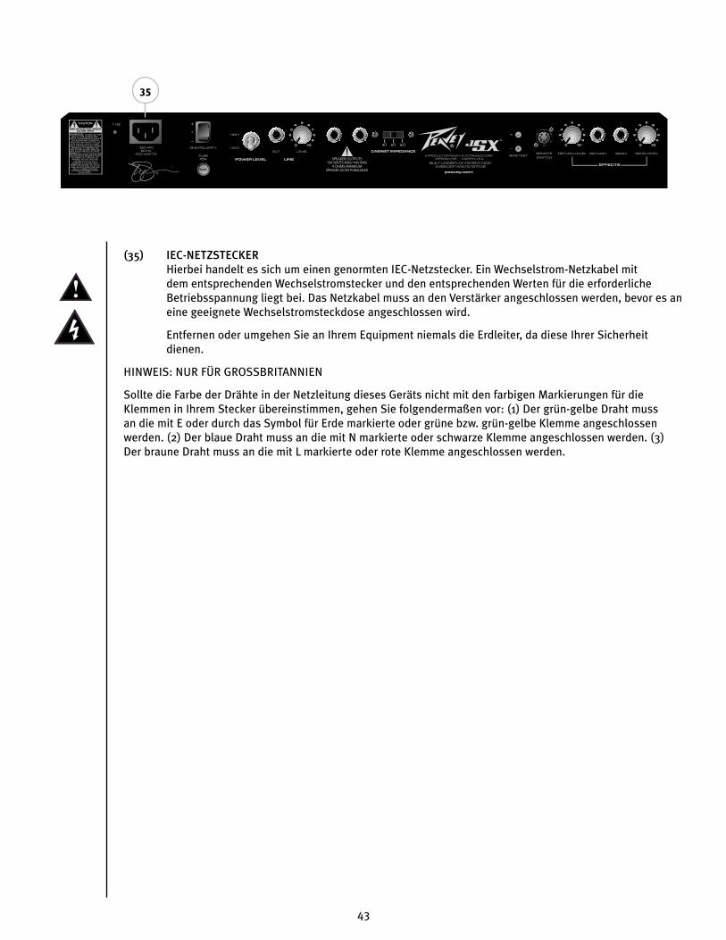
43
(35) IEC-NETZSTECKERHierbei handelt es sich um einen genormten IEC-Netzstecker. Ein Wechselstrom-Netzkabel mit dem entsprechenden Wechselstromstecker und den entsprechenden Werten für die erforderliche Betriebsspannung liegt bei. Das Netzkabel muss an den Verstärker angeschlossen werden, bevor es an eine geeignete Wechselstromsteckdose angeschlossen wird.
Entfernen oder umgehen Sie an Ihrem Equipment niemals die Erdleiter, da diese Ihrer Sicherheit dienen.
HINWEIS: NUR FÜR GROSSBRITANNIEN
Sollte die Farbe der Drähte in der Netzleitung dieses Geräts nicht mit den farbigen Markierungen für die Klemmen in Ihrem Stecker übereinstimmen, gehen Sie folgendermaßen vor: (1) Der grün-gelbe Draht muss an die mit E oder durch das Symbol für Erde markierte oder grüne bzw. grün-gelbe Klemme angeschlossen werden. (2) Der blaue Draht muss an die mit N markierte oder schwarze Klemme angeschlossen werden. (3) Der braune Draht muss an die mit L markierte oder rote Klemme angeschlossen werden.
CAUTION
FUSE FUSE
35

44
F U S S S C H A LT E R
(36) REMOTE CABLE
An diese 7-polige DIN-Buchse schließen Sie das im Lieferumfang enthaltene Fußschalter-
Anschlusskabel an und verbinden es mit dem Fußschaltereingang des Verstärkers (REMOTE SWITCH,
25). Beachten Sie, dass die Kabelverbindung bei Einschalten des Verstärkers bereits bestehen sollte.
(37) ULTRA/CRUNCH-WAHLSCHALTER
Mit diesem Schalter wird zwischen den Kanälen Ultra und Crunch des Verstärkers umgeschaltet.
Die LED leuchtet auf, wenn der Ultra-Kanal gewählt ist. Leuchtet die LED nicht, ist der Crunch-Kanal
gewählt. Der CLEAN-WAHLSCHALTER (38) muss sich im BYPASS-Modus befinden, damit Ultra- bzw.
Crunch-Kanal aktiviert werden können.
(38) CLEAN-WAHLSCHALTER
Mit diesem Schalter wird der Clean-Kanal gewählt und unabhängig von der Position des ULTRA/
CRUNCH-WAHLSCHALTERS (37) aktiviert. Die LED leuchtet auf, wenn der Clean-Kanal gewählt ist.
Dieser Schalter muss sich im BYPASS-Modus befinden (LED leuchtet nicht), damit der ULTRA/CRUNCH-
WAHLSCHALTER (37) genutzt werden kann.
(39) EFFEKTWAHLSCHALTER
Mit diesem Schalter wird die Effektschleife (22-25) des Verstärkers aktiviert. Die LED leuchtet auf,
wenn die Effektschleife aktiviert ist.
37 39
36
38

45
JSX™ 212 Block Diagram

46
JSX™ 212TECHNISCHE DATEN
Note: For proper ventilation‚ allow 24" clearance from nearest combustible surface.
ENDSTUFE:Röhren:Vier EL34-Röhren mit 12AX7-Treiber Nennleistung und Nennlast:130 watts RMS an 16, 8 oder 4 ohm
Leistung bei Clipping:(typisch bei 5% THD, 1 kHz, 120 V Wechselstromleitung)130 watts RMS an 16, 8 oder 4 ohm
Frequenzgang:+/-3 dB, 50 Hz bis 20 kHz bei 90 W RMS an 8 ohm
Brummen und Rauschen:Mehr als 76 dB unter Nennleistung
Leistungsaufnahme: USA: 400 watt, 50/60 Hz, 120 V WechselstromExport: 400 watt, 60 Hz, 220-230/240 V Wechselstrom
VORVERSTÄRKER:Röhren:Drei 12AX7-Röhren
Die folgenden technischen Daten wurden bei 1 kHz mit folgenden Reglervoreinstellungen gemessen:Alle EQ-Regler bei 5Lautstärke Ultra bzw. Crunch bei 10Master Volume bei 5Resonance- und Presence-Regler bei 5Effects Send bei 0Effects Return bei 10Nennpegel mit Gain bei 5Mindestpegel mit Gain bei 10Alle Pegel um 6 dB angehoben bei Einsatz des Low-Gain-Eingangs
Clean-Kanal:Nenneingangspegel: -10 dBV, 300 mV RMSMindesteingangspegel: -22 dBV, 80 mV RMSHöchsteingangspegel: 0 dBV, 1 mV RMS
Crunch-Kanal:Nenneingangspegel: -60 dBV, 1 mV RMSMindesteingangspegel: -90 dBV, 0,03 mV RMS
Ultra-Kanal:Nenneingangspegel: -70 dBV, 0,3 mV RMSMindesteingangspegel: -90 dBV, 0,03 mV RMS
Effects Send:Verbraucherimpedanz: 47 kohm oder darüber Mindestausgang: -10 dBV, 300 mV RMS Höchstausgang: 0 dBV, 1 V RMS
Effects Return:Impedanz: High Z, 80 kohm Mindesteingangsempfindlichkeit: -10 dBV, 300 mV RMS Höchsteingangsempfindlichkeit: 0 dBV, 1 V RMS
Line-Ausgang:Verbraucherimpedanz: 47 kohm oder darüber Einstellbarer Ausgang: +/- 20 dBV, 0,1 V RMS bis 10 V RMS
Fußschalter:Spezieller Dreitasten-Fußschalter aus Metall mit LED-Anzeigen und abziehbarem Kabel (beiliegend) zur Auswahl der drei Kanäle und Deaktivierung der Effektschleife.
Systembrummen und -rauschen bei Nenneingangspegel:(Clean-Kanal -20 Hz bis 20 kHz ungewichtet)Mehr als 74 dB unter Nennleistung(Einstellbare Noise-Gate-Schaltung für Ultra- und Crunch-Kanal)
Abgleich: Passiver Dreiband-EQ (Bass, Mid, Treble) am Clean-Kanal Separate aktive Dreiband-EQs (Bass, Mid, Treble, +/-12 dB) an Ultra- und Clean-Kanal Fat-Schalter an Ultra- und Crunch-Kanal zur Veränderung des Ansprechens bei niedrigen Frequenzen Resonance- und Presence-Damping-EQ-Regler an der Endstufe
Abmessungen und Gewicht:HxBxT 521 mm x 673 mm x 279 mm38,3 kg
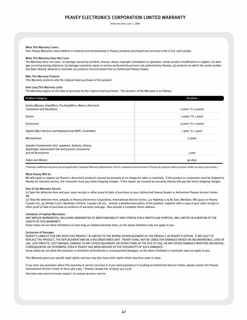
47
PEAVEY ELECTRONICS CORPORATION LIMITED WARRANTYEffective Date: July 1, 1998
What This Warranty CoversYour Peavey Warranty covers defects in material and workmanship in Peavey products purchased and serviced in the U.S.A. and Canada.
What This Warranty Does Not CoverThe Warranty does not cover: (1) damage caused by accident, misuse, abuse, improper installation or operation, rental, product modification or neglect; (2) dam-age occurring during shipment; (3) damage caused by repair or service performed by persons not authorized by Peavey; (4) products on which the serial number has been altered, defaced or removed; (5) products not purchased from an Authorized Peavey Dealer.
Who This Warranty ProtectsThis Warranty protects only the original retail purchaser of the product.
How Long This Warranty LastsThe Warranty begins on the date of purchase by the original retail purchaser. The duration of the Warranty is as follows:
Product Category Duration
Guitars/Basses, Amplifiers, Pre-Amplifiers, Mixers, Electronic Crossovers and Equalizers 2 years *(+ 3 years)
Drums 2 years *(+ 1 year)
Enclosures 3 years *(+ 2 years) Digital Effect Devices and Keyboard and MIDI Controllers 1 year *(+ 1 year)
Microphones 2 years Speaker Components (incl. speakers, baskets, drivers, diaphragm replacement kits and passive crossovers) and all Accessories 1 year
Tubes and Meters 90 days
[*Denotes additional warranty period applicable if optional Warranty Registration Card is completed and returned to Peavey by original retail purchaser within 90 days of purchase.]
What Peavey Will DoWe will repair or replace (at Peavey's discretion) products covered by warranty at no charge for labor or materials. If the product or component must be shipped to Peavey for warranty service, the consumer must pay initial shipping charges. If the repairs are covered by warranty, Peavey will pay the return shipping charges.
How To Get Warranty Service(1) Take the defective item and your sales receipt or other proof of date of purchase to your Authorized Peavey Dealer or Authorized Peavey Service Center. OR(2) Ship the defective item, prepaid, to Peavey Electronics Corporation, International Service Center, 412 Highway 11 & 80 East, Meridian, MS 39301 or Peavey Canada Ltd., 95 Shields Court, Markham, Ontario, Canada L3R 9T5. Include a detailed description of the problem, together with a copy of your sales receipt or other proof of date of purchase as evidence of warranty coverage. Also provide a complete return address. Limitation of Implied WarrantiesANY IMPLIED WARRANTIES, INCLUDING WARRANTIES OF MERCHANTABILITY AND FITNESS FOR A PARTICULAR PURPOSE, ARE LIMITED IN DURATION TO THE LENGTH OF THIS WARRANTY. Some states do not allow limitations on how long an implied warranty lasts, so the above limitation may not apply to you.
Exclusions of DamagesPEAVEY'S LIABILITY FOR ANY DEFECTIVE PRODUCT IS LIMITED TO THE REPAIR OR REPLACEMENT OF THE PRODUCT, AT PEAVEY'S OPTION. IF WE ELECT TO REPLACE THE PRODUCT, THE REPLACEMENT MAY BE A RECONDITIONED UNIT. PEAVEY SHALL NOT BE LIABLE FOR DAMAGES BASED ON INCONVENIENCE, LOSS OF USE, LOST PROFITS, LOST SAVINGS, DAMAGE TO ANY OTHER EQUIPMENT OR OTHER ITEMS AT THE SITE OF USE, OR ANY OTHER DAMAGES WHETHER INCIDENTAL, CONSEQUENTIAL OR OTHERWISE, EVEN IF PEAVEY HAS BEEN ADVISED OF THE POSSIBILITY OF SUCH DAMAGES.Some states do not allow the exclusion or limitation of incidental or consequential damages, so the above limitation or exclusion may not apply to you.
This Warranty gives you specific legal rights, and you may also have other rights which vary from state to state. If you have any questions about this warranty or service received or if you need assistance in locating an Authorized Service Center, please contact the Peavey International Service Center at (601) 483-5365 / Peavey Canada Ltd. at (905) 475-2578.
Features and specifications subject to change without notice.

Features and specifications subject to change without notice.
Peavey Electronics Corporation • 711 A Street • Meridian • MS • 39301
(601) 483-5365 • FAX (601) 486-1278 • www.peavey.com
©2005 80304951