Embed Size (px)
Citation preview

9 A
IIWWRIC PRoPErrnR REPORT
RE31OK1 ARSMAL. ALABAMAI THE
GEORGE C. MARSHALL SPACE FLIGHT CENTE
FINAL REPORT
JULY 194
DTICCIELECTE
JAN 0 91987
S This. document was prepared under Contract CX-0001.-2-0033between Building Teetmology fnoorporated. Silver Spring. Maryland
-id the Historic American Building Survey/Historme AmericanEngineerifq R*eoKrd National Park Service
U.S. Department of the Interior
A pd-ft band aIAW*i b mom"

RNTORIC PROPERTIES REPORT
IREIrOME ARSENAL ALABAMA
Wr THE
GEORGE C. MARSHALL SPACE FLIGHT CENTRM
FINAL REPORT
JULY 194
SDTIC
E
This document was prepared under Contract CX-OCOI-2-0033between Building Technology Incorporated. Silver Spring. Maryland
and the Historic American Building Survey/Historic AmericanEngineering Record. National Park Service
U.S. Department of the Interior
- A s " .. now am
'I I a eI b4

EXECUTIVE SUMMARY
Redstone Arser~l is the headquarters of the U.S. Army Missile Command
(KICOM). It is located on approximately 40,000 acres in northern Alabama
new the town of Hunitsville. and has 1,838 buildings including laboratories,
ffight, test ranges, wild other specialized buildings and eqipment. The present
arsna dates to World War It when the site served as a chemical munitions
manuftacturing and amiiismbly canter for the Army's Chemical mid Ordniance
Corps. In 1IM, the Orcbiani k uied Missile Center was established at the
site and Redstone Arsena became the Ordnance Department's principal
center for rocket research and deveopent. Today, Redstone Arsenal is
responsibl, for managing the Army's missile and rocket per ~m.
NASA's George C. Marshall Space Flight Center Is located within the lbound-
aries of Redstone Arsenal on 1,34 acres of land leased to NASA by special
agreement with the Army. The facility'was established In 1960 and is cur-
rently one of NASA's primary centers for aerospace research, design, and
developmnt. The laboratories. test stands, and high-bay facilities at the
center can accommodate Vaece system eomponents through all stages of
development wondfight readiness testing.
The Redstone Rocket Test Stand (Building 4665), located at the Marshall
Space Flight Center, is a Category I historic property listed on the Nation~al
Register of Historic, Places. Several specialized test facilities at the Marshall
Space Flight Center as-e significant engineering structures associated with the
national space program and are Category If historic properties: Neutral

Douyal Simulator, Solid Rocket Motor Propulsion and Structural Test Facility,
Structures and Mechmnics Laboratory, Acoustic Model Engine Test Facility,
Structural Dynamics Test Facility, Propumlsion and Structural Test Facility,
and High Reynolds Number Wind Tunnel. There are two Category MI historic
propertiew Fire Station #3 (Building 7102) and the Harris Residence
(Building 8012). Both hae. local importance to the history of Redstone
Arsenal.
I- e~ I" i For
ti miinounc OdJj* ~ Tlatio
Distrlialt~iof/
A'vailabllltV CodeSAvail and/or
Dt!Itt special 1

CONTENTS
Executive Summary
PREFACE. ............. 1.............
INTRODUCTION ...... .......... . .... . ...... 3
Scope ..................................... 3
Methodology ....... ................ 4
2. HISTORICAL OVERVIEW...... 12
BDakground. ................... 12
Huntsville Arsenah Site Development ................... 14
Gulf Chemical Warfare Depot: Site Development ......... 21
Redstone Ordnance Plant: Site Development .............. 22
Redtone Arsenal: 1949 - Present .... ................... 29
Marshall Space Flight Center: Background ............... 32
Marshall Space Flight Center: , Description ofMajor Facilities .................................... 33
3. PRESERVATION RECOMMENDATIONS ........................ 50
Background ......... *.................................. 50
Category I Historle Properties ............................ 55
Category I7 Historic Properties ........................... 56
Category iD Historic Properties ........................... 57
BIBLIOGRAPHY .......................................... 62

PREFACE
This report presents the results of an historic properties survey of Redstone
Arsenal, Huntsville, Alabama, including NASA's George C. Marshall Space
Flight Center. Prepared for the United States Army Materiel Development
and Readiness Command (DARCOM), the report is Intended to assist the
Army in bringing this installation into compliance with the National Historic
Preservatlon Act of 196 and Its amendments,' and related federal laws and
regulations. To this end, the report focures on the identification, evaluation,
documentation, nomination, and preservation of historic properties at Redstone
Arsenal Chapter 1, sets forth the survey's scope and methodology; Chapter 2
presents an architectural, historical, and technological overview of the installa-
tion and its properties; and Chapter 3 identifies significant properties by
Army category and sets forth preservation recommendations. Illustrations
and an annotated bibliography supplement the text
This report is part of a program initiated through a memorandum of agree-
ment between the National Park Service, Department of the Interior, and the
U.S. Department of the Array. The program covers 74 DARCOM installations
and has two components: 1) a survey of historic properties (districts, buildings,
structures, and objects), and 2) the development of archeological overviews.
Stanley H. Fried, Chief, Real Estate Branch of Headquarters DARCOM,
directed the program for the Army, and Dr. Robert J. Kapsch, Chief of the
Historic American Buildings Survey/Historic American Engineering Record
(HABS/HAER) directed the program for the National Park Service. Sally
Kress Tompkins was program manager, and Robie S. Lange was project
dB , 1
a i I I I;I 7.

manager for the historic properties survey. Technical assistance was pro-
vided by Donald C. Jackson.
Building Technology Incorporated acted as primary contractor to HABS/HA R
for the historic properties survey. William A. Brenner was BTl's principal-in-
charge and Dr. Larry D. Lankton was the chief technical consultant. Major
subcontractors were the MacDonald and Mack Partnership and Melvyn Gre
and Associates. The authors of this report were David G. Buchanan and
John P. Johnson. The authors gratefully. acknowledge the help and enthu-
siasm of Morris W. Schroder, Environmental Quality Coordinator at Re(L-to e
Arsenal
The complete HABS/HAER documentation for these installations will be
includ%-d in the HABS/HAER collections at the Library of Congress, Prints
and Photographs Division, under the designations HAER No. AL-9.
2

Chapter I
INTRODUCTION
SCOPE
This report is based on an historic properties survey conducted in 1983 of all
Army-owned properties located within the official boundaries of Redstone
Arsenal. The survey included the following tasks:
Completion of documentary research on the history of the installation
and itq properties, and general research on the history of 1) chemical
munitions manufacture in World War II, and 2) NASA space booster
programs.
a Completion of a field inventory of all properties at the installation.
0 Preparation of an architectural, historical, and technological overview
for the installation.
0 Evaluation of historic properties and development of recommendations
for preservation of these properties.
Also completed as a part of the historic -'operties survey of the installation,
but not included in this report, are HA3S/HAER Inventory cards for 40 individual
properties. These cards, which constitute HABS/HAER Documentation Level IV,
will be provided to the Department of the Army. Archival copies of the
cards, with their accompanying photographic negatives, will be transmitted
to the HABS/HAER collections at the Library of Congress.
The methodology used to complete these tasks is described in the following
section of this report.
3

METHODOLOGY
1. Documentary Research
The Redstone Arsenal has a history of chemical munitions manufacture
and research and development in the field of rocketry. Research on the
development of the arsenal and on specific aspects of the arsenal's
activities in World War II and the post-war period was conducted at the
Library of Congress and at the Historian's and Facilities Engineer's
office3 at Redstone.
The George C. Marshall Space Flight Center, located at the arsenal, is
one of NASA's primary centers for the design and development of space
transportation and orbital systems, and scientific &pplications and payloads.
Background research pertaining to NASA rocket programs Was conducted
at the Library of Congress and research on specific properties at the
Marshall Space Flight Center was conducted through the Master Planning
Office and the Technical Library of the space flight center. The Alabama
State Historic Preservation Office identified the Redstone Rocket Test
Stand, which is listed on the National Register of Historic' Places, as
the only historic property' at Redstone in their records.
Army records used for the field inventory included Real Property Inventory
(RPI) printouts that listed all officially recorded buildings and structures
by facility classification' and date of construction; the installation's
property record cards; base -maps and photographs supplied by installation
personnel; and installation master planning and environmental assessment
and related reports and documents. A complete listing of this documen-
tary material may be found in the bibliography.
4

2. Field Inventory
The field inventory wis conducted by David G. Buchanan and John P.
Johnson during a one-week period in May 1983. Morris W. Schroder,
Environmental Quality Coordinator of Redstone Arsenal, served: as the
point of contact for the survey team and provided base maps, environ-
mental assessment reports, and cultural resources reports. Ron Hagler,
also of the Environmental Office, provided assistance and supplied maps
and other documents. Mary Cagle, Historian, MICOM, and Mike Baker,
Archivist, supplied installation histories and historic photographs, which
were invaluable in'conducting the inventory and preparing, the historical
overview. Carrie Hensen, Real Property Officer at Redstone Arsenal,
provided access to the real property cards.' Frank Showalter, Environ-
mental and Energy Coordinator, Thiokol Corporation, escorted the survey
team during its field inventory of Thiokol production areas at Redstone
Arsenal; At the Marshall Space Flight Center, Robert G. Sheppard,
Director of Management Operations, provided historical materials and
facilitated the invento-y by coordinating security and photography pro-
cedures. Ramon J. Samaniego, Jr., Mastpr Planning Office, supplied
real property records, master planning documents, and photographs of
NASA facilities at the space flight center.
Field inventory procedures were based on the HABS/HAER Guidelines
for Inventories of Historic Buildings and Engineering and Industrial
Structures.1 All areas and properties were visually surveyed. Building
locations and approximate dates of construction were noted from the
installation's property records and fiel~dverified.
11

Field inventory forms were prepared for, and black and white 35 mm
photographs taken of all buildings and structures through 1945 except
basic utilitarian structures of no architectural, historical, or technological
interest. When groups of similar ("prototypical") buildings were found,
one field form was normally prepared to represent all buildings of that
type. Field inventory forms were also completed for representative
post-1945 buildings and structures. 2 Information collected on the field
forms was later evaluated, condensed, and transferred to HABS/HAER
Inventory cards.
S3. Historic Overview
A combined architectu~ral, historical, and technological overview was
prepared from information developed from the documentary research and
the field inventory. It was written in two parts: 1) an introductory
description of the installation, and 2) a history of the installation by
periods of developmeit, beginning with pre-military land uses. Maps and
photographs were selected to supplement the text when appropriate.
The..objectives of the overview were to 1) establish the periods of major
construction at the installation, 2) ider.tify important events and indi-
viduals associated with specific historic properties, 3) 'describe patterns
and locatiors of historic property types, and 4) analyze specific building
and industrial technologies employed at the installation.
4. Property Evaluation and Pres'.rvation Measures
Based on information developed in the historical overviews, properties
were, first evaluated for historical significance in accordance with the
6
";1 AN

elegibility criteria for nomination to the National Register of Historic
Places. These criteria require that eligible properties possess Integrity
of location, design, setting, materials, workmanship, feeling, and associa-
tion, and that they meet one or more of the following:3
A. Are associated with events that have made a significant contribution
to the broad patterns of our history.
B. Are associated with the lives of persons significant In the nation's
past.
C. Embody the distinctive characteristics of a type, period, or m.thod
of construction, represent the work of a master, possess high artistic
values, or represent a significant and distinguishable entity whose
components may lack individual distinction.
D. Have yielded, or may be likely to yield, information important in
pre-history or history.
Properties thus evaluated were further assessed for placement in one of
five Army historic property categories as described in Army Regulation
420-40:4
Category I Properties of major importance
Category II Properties of importance
Category IM Properties of minor importance
Category W Properties of little or no importance
Category V Properties detrimental to the significance of
of adjacent historic properties
7
111 R M '

Based on an extensive review of the architectural, historical, and techno-
logical resources identified on DARCOM installations nationwide, four
criteria were developed to help determine the appropriate categorization
level for each Army property. These criteria were used to assess the
importance not only of properties oi traditional historical interest, but
of the vast number of standardized or prototypical buildings, structures,
and pro&,ction processes that were built and put into service during
World'War f, as well as of properties associated with many post-war
teehnological achievements. The four criteria were often used in com-
bination and are as follows:
1) Degree of impc.-tance as a work of architectural, engineerin., or
indust.ial design. This criterion took into account the qualitative
factors by which design is normally judi,,d: artistic merit, work-
manship, appropriate use of materials.. and functionality.
2) Degree of rarity as a remaining example of a once widely used
architectural, engineering, or industrial design or process. This
Scriterion was applied primarily to the n-;..ny standardized or proto-
typical DARCOIM buildings, structures, o. industrial processes. The
more widespread or influential the design or process, the greater
the importance of the remaining examples of the design or process
was considered to be. This criterion was also use,' for non-military
structures such as farmhouses and other once prevalent building
types.

SDge of Integity or eompletness. This criteon am p the
mrent sotim .a and I .M of a b"O . structure,
arcdhtectural ammblage, or rocs on to Its original or
most historcaily important conditit eapperuce, mu functiMon
Thome pWortles that were highly in were generally Oonuld'ed
of prester importn then those that were not.
4) Perm* of amoelation with an Impomant persmnpr ram, or event.
This crtarion was wd to examine the relatini-tip d a property to
a famous pesonage, wartime pro , or similar faco that lent the
property qweca importce.
The majority of DARCOM properties we~built just prior to or duing,
World War IL and special attention was iven to their evahmtion. Thore
that still remain do not often poe indvual iartae, but oLlee-
tively they represent the remnants of a esat constructioa undataking
whose arehitectural, historlal. and telm Mogftal importwi needed to
be mesed before their numbers dminl further. This ameesment
centered on an extensive review of the illtary eouwtruetion of the
1940-1945 period. and its contribution to the history of World War 0
and the post-war Army landepe.
Because te-hMology has advanced so rapiy sinc* the war. post-World
War 11 properties were also given attentii n. The"m proper•tes were
evaluated in terms o( the nation's more @e'!ent aceomplishments in
weaponry, roeketry, electrcnies and relstatý teehnologleadel " scientifle
endeavors. Thus the traditional definition of "historie" as a property 50
Nil I

or mre years cad was not •erms in the amessaent of either World
War ! or post-wer DARCOM bu ingsnid structures; rather, the his-
tori.e iwortance of all properties was evaluated as completely as pop-
ible rgrdlesm of age.
Prop&.ty designations by eateory we expected to be useful for approxi-
mately ten ye ftes, er which all categorizatiton solxdd be reviewed and
updated.
Following this categoetration proeedure, CateMry L IL and MI historic
propertis were analyzed in terms of:
Current structural conditlon and state of rp . This information
was taken from the field inventory forms and photogapha. and was
often supplemented by r cheeking with facilities enginmerng
* The nature of poNiwe future adtr-e Imnpets to the propyrty This
krformatIm was gathered from the installatim's master planning
doeuments and ,echeaked with facilities engineering personneL
9ased on the above eowiderations, the general preservation r.eommends-
tions presented in Chapter 3 for Category L IL and M historic properties
were developed. Special Ixeservation rmeommendstlons werv created for
individual properties as circumstances required.
10

L. Report Review
* Prior to being completed in final farm, this report was ubjected to an
kgHoime review by Building Technology In.%orporated. It ass then sent
*i dr ~aft to the suiJect Installation for comment and clearace and. with
It: associated historical materials, to HABS/HAER staff for technical
review. When the Installation cleared the report, adtkdiu draft copies
were sent to DARCOM, the appropriate State Historic Preservation
Officer, and, when requested, to the archeological contractor performing
paralliel work at the installation. The report was revised oasd on all
comments collected, then published in final form.
NOTES
1. Historic American Buildings Survey/Historic Amewican Engineering Record,National Park Service, Guidelines for Inventories of Historic Buildings
and !ingw and bUtdustrial Structures (unpublished chart. 1982).
2. Representative poet-World War 9 buildings and structures were definedas properties that were: (a) "representative" by virtue of constructiontype, architectural type, function, or a combination of these, (b) ofobvk-us Category L 11, or IIl historic Importance, or (c) prominent onthe installat*on by virtue of size, location, or other distinetive feature.
3. National Park Service, Now to Complete National Register Forms(Washington, D.C.: U.S. Government Printing office, January 1977)6
4.. Armiy Regulation 420-40, Historic Preservation (Headquarters U.S. Army:Washiington, D.C., 15 April 198M)
I II IIIIV NM ~ 11

C-,te
HWLORICAL OVERVIEW
BACKGROUND
Redstone Arsnl, located neow Hun tuvi. A1,!ail Is the headquarters of
the U.&. Army Missile Command (MICOM), the major DARCOM subordinate
coommand that manages the Army's missile and rocket prupram. Redstone's
major responsiblities include research, development, procurement, and continued
support of the Army's missile and rocket weapons systems. Occup~ying approxi-
mately 40,000 acres of land, the Arsenal's faciHltis includs diinistrative
buildingu, laboratories, flight test ranges, and other speclallsedbuilfdings and
equipment. (iullstration 1)
Redstone Arsenal is also the location of the U.S. Army Mi=Uil and Munitions
Center and School. Established on 1 December 1952. the school trains military
and civilian persone Iin the design, development, tiest nig. and deployment of
missiles and munitions.
The Thiokol Corporation is a major contractor that has. operated government
owned facilities at Redstone Arsenal since L.949. Thiokol is esponsible for
research, development, and pinxdsctlon of solid propulsion systems. The OAF
Corporat ion operates an iron carbonyl plat at Redstone Arsenal under a
lease agreement with the Army.
N'ASA's George C. Marshall Space Flight Center (MSFC) 1s situated on 1,840
sctes in the c~enter of. Redstone Arsenal (mee separate section, on MSFC).
N4ASA operates the facility under a special leane agreement with the Army.

SamS
.!- REDSTONE 53
133

present Redstone Arenal was established in World War II as a chemical
mmunition manufacturing center by the Chemical Corps and the Ordnance
orpe of the U.S. Army. Originally known as the Siebert Arsenal Project,
I center was iocated on the Tennmessee River in northern Alabama. The
Amy acquired the site (approximately 37,000 acres of pastureland and farm-
|rd in late 1941 and early 1942.
1%e center was built as thre installations: the Huntsville Arsenal, the
I edstone Ordnance Plant, and the Gulf Chemical Warfare Depot. The
I untsville Arsenal was located on the northwest side of the site and the
i edstone Ordnance Plant in the southeast corner. The operation of both
ts was closely integrated: the arsenal manufactured and loeded chemical
ammunition shells, and the ordnance plant assembled the explosives and pro-
duced the completed rounds of chemical ammunition. The Gulf Chemical
Warfare Depot, situated in the southern portion of the site nea the
I enneue River, received, stored, and shipped ehemieal warfare materiel.1
HUNTSVILLE ARSENAL: SITE DEVELOPMENT
early 1941, the Ecgewood Arsenal in Maryland was the Chemical Warfare
& ice's only chemical manufacturing Installation. Because Edgewood had
little room to expand, a site near Huntsville, Alabama, was chosen to serve
an extension of Edpwood for the manufacture of toxic agents, smoke,
and incendiary materiel. The Army selected the Huntsville site because it
was a large tract of land accessible to rail and river transportation and to
eleetric power from the Tennessee Valley Authority. 2
14

ba July 1941, contarction of the Huntsville Arsenal was authorized and land
was acquired by condemnation proceedings. The War Department signed an
architectural and engineeing services contract with Whitman, Requardt, and
Smith of Baltimore, Maryland, and construction contracts with C. G. Kershaw
Contracting Co. of BirminWam, Alabama; Walter Butler Co. of St. Paul,
Minnesota; and Fngineers Limited of San Francisco, California. CoL Rollo C.
Ditto was the first commanding officer and coordinated the planning and
construction efforts. 3
Initial plans for the installation called for 11 manufacturing plants and four
chemieal-ioeding plants. Storage facilities, laboratories, shop buildings, offices,
housing, and a hospital were also included, as were the utilities and support
services, Including roads and railroads, necessary for the production, storage
mid shipping of chemical munitions. 4 Principal manufacturing facilities planned
for the Huntsville Arsenal included plants for the production of mustard gas,
lewisite, phosgene, white phosphorous, iron earbonyl, white smoke munitions5
and incendiaries, tear gas, and colored smoke.
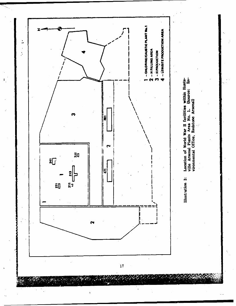
Six mustard gas ("H") manufacturing planti were constructed at the arsenal
in 1942. The first four plants were located in Area No. I and the other two
in Area No. 2. Each plant consisted of a sulphur monochloride building, an
ethylene generator building, and a mustard reactor building, and each was
designed to produce 24 tonm of mustard gas per day, with a maximum capac-
ity of 40 tons per day. All plants were in operation by the end of 1942, but
most were operated for less than one year. Production of mustard gas offi-
cially ceased at Huntsville Arsenal on May 28, 1943. (illustrations 2-4)
15
111 III I

PPLANTSAREA 3
PLANTSNT
AREA 2
REDSTONE
ORDNANCELINES 1THRU 6
Illustration 2: Map showing World War 11 locations of HuntsvilleArsenal Manufacturing and Loading Plants Areas1-3, and Redstone Ordnance Line 1-6. (Source:Environmental Office, Redstone Arsenal)
16
* -I
.1 Im
Ce,4
17c
All

I-O.OKMIME PLAte No.23JISOVL CHLORIDES..NUTAN 1m) OPERATiONS. REACTORS US4aOL INCENDIARY 90M9 FILLING&^JWOENF64AMONY I MON
I-ARSENICUTICHLORV! IDf7
18.1

Two chlorine plants constructed in 1942 supported the production of mustard
gas. The plants, one In Area No. I and the other in Area No, 2, could
produce either liquid or gaseous chlorine, a necessary ingredient for the
manufacture of mustard gas. Both plants operated from May 1942 to
July 1945.
Two mustard gas filling plants, located in Area No. 1, were completed in
early 1942. The first items produced in these plants were 105-mm M60
shells. Production began in April 1942 and continued until March 1944, when
both plants were placed on standby. The plant in Area No. 2 was reactivated
later on two separate occasions.
Originally, Huntsville Arsenal was intended to have six lewisite plants,. but
only four plants were actually operated . dring World War 11. (Plants No. 5
and 6 were completed except for minor items of equipment, but neither
plant was activated.) These four plants were all operable by May 1943.
Two plants stood in Area No. 1, and two in Area No. 2. The plants ceased
operation in October 1943, when the Huntsville Arsenal permanently halted
the manufacture of lewisite. Two other facilities, a thionyl chloride plant
and an arsenic trichloride plant, produced products necessary for the manu-
facture of lewisite. Both plants were located in Area No. 2; the chloride
plant was operational from March to October 1943, and the arsenic plant was
operational from March to November 1943.
Huntsville Arsenal's only phosgene plant, located in Area No. 2, operated
from February 1944, to January 1945. The facility ;ncluded a carbon mon-
oxide generating plant, a container filling shed, a catalyzer building, various
19
- - - - - - - - - - - - -

storage tanks, and an office building. A phosgene filling plant situated imme-
diately adjacent to this complex had six filling stations, each capable of
filling 40 bo'nbs per eight hour shift. The plant filled 500-pound M78 bombs
from 15-17 April 1944, and 1,000-pound M79 bombs from 27 April until the
supply of phosgene was depleted on 17 January 1945.
A white phosphorus filling plant occupied a site on the west side of Area
No. 1. Between May 1942 and August 1945, this plant filled ten different
munitions, including artillery and mortar shells, grenades, and igniter tubes.
During World War ]1 Huntsville Arsenal also produced M4 white smoke pots,
two types of tear gas grenades and four types of incendiary oil munitions,
and colored smoke for grenades and canisters. An iron carbonyl plant at the
arsenal served as a standby plant. This facility, located in Area No. 2, has
been operated by the GAF Corporation since 1949.
Following V.J. Day, Army activities at the Huntsville Arsenal were curtailed.
The arsenal was designated a storage center for vast amounts of war reserve
materiel. In 1946, chlorine manufacturing plants No. 1 and 2 were leased
for five years to the Solvay Process Division of Allied Chemical and Dye
Corporation. The Keller Motors Corporation took a fifteen year lease on
facilities to manufacture gas masks, and the Calabma Chemical Company
took a fifteen year lease on facilities to manufacture organic chemicals,
insecticides, and related products.6
In 1947, the Department of the Army declared the Huntsville Arsenal surplus
to the needs of the Army. The chief of the Chemical Corpz reversed this
20

decision in 1948 and placed the arsenal on "standby" status. Early in 1949,
the decision was again reversed and the arsenal was placed for sale. Plans
were made to ship serviceable supplies to other installations, demilitarize
unserviceable chemical materiel, dispose of property through sale cr salvage,
and decontaminate production lines. Redstone Arsenal, acting in a caretaker
capacity, provided security and maintained essential utilities. In April 1950,
Huntsville Arsenal was completely deactivated and was transferred from the
Chemical Corps to Army Ordnance. Its facilities were consolidated with
tloc:o of Redstone Arsenal. 7
GULF CHEMICAL WARFARE DEPOT: SITE DEVELOPMENT
The operations of the Huntsville Arsenal and the Gulf Chemical Warfare
Depot closely intertwined. Of the nearly 33,000 acres comprising the orig-
inal Huntsville Arsenal, approximately 8,010 were planned as a depot site.
This acreage was located in the southern portion of the arsenal along the
Tennessee River. In March 1942, the depot was activated as a separate
installation, known as Huntsville Chemical Warfare Depot. Its name changed
in August 1943 to the Gulf Chemical Warfare Depot. In August 1946, the
word "Warfare" was dropped from this title.
The depot received, stored, and shipped chemical warfare materiel, including
bulk chemicals, decontaminating apparatus, and protective materials. It
covered nearly twelve square miles and was divided into three principal
areas: the toxic gas yard, the munitions branch, and the warehouse area.
All were in operation by October 1942. By early 1943, the depot consisted
of seven warehouses, 370 igloos, 55 above-ground magazines, several outdoor
21
plv* MIi

storage areas, twelve miles of railroad track, and dock facilities on the
Tennessee River.8
In January 1947, the Gulf Chemical Depot was abolished as a separate entity
and its functions transferred to the Huntsville Arsenal.
REDSTONE ORDNANCE PLANT: SITE DEVELOPMENT
The Army erected the Redstone Ordnance Plant as a chemical ammunition
assembly plant on a site adjacent to the Huntsville Arsenal. Tho original
layout included two burster-loading assembly lines wnd two chemical ammunl-
tion assembly lines. Storage facilities, administrative facilities, housing, and
utilities were also built.9 (Illustrations 2 and 5)
Production Line No. 1 was scheduled for completion first, but due to construe-
tion delays, Production Lines No. 1 and 2 were constructed simultaneously.
Both lines, completed by 1942, loaded and assembled burster tubes. The
loading plants at Redstone were designed to utilize the cast method. This
process, developed at Picatinny Arser,al in 1941, centers on forming the
explosive tetrytql into predetermined shapes and sizes for later use.
(Illustrations 6-7)
Production Lines No. 3 and 4 were completed in April and August of 1942,
respectively. These lines loaded and assembled chemical ammunition. All
major ammunition components, such as cartridge cases and empty shells.
came, from private manufacturers. Other Army ordnance plants produced
minor components such as fuses, boosters, propellant charges, and primers.,
22

PLANT M& I
"Redtone Arsenal
23R"O

Illustration 6: Operations at. Redstone Ordnance Line 1 duringWorld War It consistedý of mixing, melting, andpouring the explosive tetrytol in the manufactureof burster charges. (Source: Historian's Offrice,Redstone Arsenal)
24

3~S~Polls" 4w PA Im A.1a Pwfoalit I& NoWAN
Ilustration 7: Operations at Redstone ordnance Line 2 duringWorld War 11 consisted of mixing, melt 'ing, andpouring the explosive tetrytol in the manufactureof demolition blocks and burster charges. (Source:Historian's Office, Redstone Arsenal)
25

which were shipped to Redstone for loadfng and asembly. After inpecting
. mnd testing the components, Redstone sent the empty shell and burster easing
to the Huntsville AmnaL Hoe, the dhelb were filled with the appropriate
*chemicals, sealed, and returned to Redstone for assembly into complete
rounds of chemical ammunition. (Illustration 6)
The first four production lines at the Redstone Ordnance Plant were esentially
completed by the summer of 1942. A fifth production line, designed to
asemble 155-mm shells and chemical bombs, was eonstructed in August 1942
and was ready for production by January 1943.10 (llustretion 9)
In February 1943, the plant's name changed to the Redstone Arsenal, and in
January 1945, the arsenal announced an expansion program costing $5.5 million.
This program, essentially completed by V. J. Day, greatly expanded production
output. A melt-pou' building, two screening and storage buildings, and a
change house added to Production Line No. I increased production on this-
line to 200,000 pounds of tetrytol bursters per month. Additions to Producticn
Line No. 2 included three production tulIdings, storage facilities, and related
utilities. Alterations to Line No. 3 included new buildings for reprocessing
ammunition, paint storage, and the extensive renovation of existing, buildings
to adapt the line to the mechanized assembly of 105-mm 'shells. Additions
to Line No. 4 increased production capacity to 650,000 rounds of 81-mm
chemical mortar shells per month, and changes to Production Line No. 5
more than tripled the production capacity for 155-mm chemical shells -
from 58,000 to 190,000 projectiles per month. Also included in the expansion
program were plans for a sixth production line to handle assembly of 81-mm
26

44t;
Illustration 8: Operations at Redstone Ordnance Line 3 duringWorld War Il included the assembly of completeroun~ds of chemical ammuntion. (Source: H-istor-ian's Office, Redstone Arsenal)
27I

Seain &Straping B030s
Illustration 9: Operations at Redstone Ordnance Line 5 du ingWorld War 11 included the assembly and packaingof ammunition and chemical bombs. (Source:Historian's Office, Redstone Arsenal)
28

chemlesil mortw and 105mm howitzer chemical shells. This line was con-
* gsructed but never used.1
* Activity at the Redstone Arsenal slowed rapidly following V.J. Day. Produc-
tion ot ammuniltion ceased on 17 August 1945. The Army decontaminated
production lines and placed them on standb~y status. Renovation and salvage
of wartime materiel continued until February 1947 when the Redstone Arsenal
was placed on standby status.
In 1949, the Government contracted with the Rohm and Haeas Company of
Philadelphia and the Thiokol Corporation of Trenton, New Jersey, to perform
researh on rocket prope"ants. Both eon. penies occupied space In the, vacant
production line facilities at Redstone Ar sen al. 12
The Chief of Ordnance reactivated Redstone ALrsenal in June 1949 to serve
as a center for research and development in the field of rocketry. In July,
the Army officially announced that the rocket program at the Ordnance
Research and Development 'Division in Fort Bliss, Texas would be moved to
Redstone.. With the arrival in 1950 of 120 German scientists, headed by Dr.
Wernher von Braun, and a complement of officers from Fort Bliss, the
Ordnance Cuided Missile Center was established at Redstone and the arsenal
entered the. missile era.
REDSTONE ARSENAL: 1949 -PRESENT
Redstone Arsenal's first mission after its reactivation in 1949 centered on
rocket-related research and development. This included basic and applied
research, development and testing of free rockets, jet-assisted take-off engines
29

(JATO's), solid propellant fuels, and other related items. With the arrival of
the von Braun group in 1950, Redstone became responsible for the research
and development of guided missiles. The arsenal's research program later
expanded to include anti-aircraft rockets, rocket launchers, aerial tow targets,
and liquid and solid propellant rocket fuels, liquid oxygen and other industrialgases13
Rocket research and development activities were located in the old Redstone
Arsenal area irn the southeast eorner, of the site. Guided missile research
and development activities were conducted m the chemical plant areas and
the headquarters area of the former Huntsville Arsenal. In September 1952,
both centers were combined to form the Ordnance Missile Laboratories. The
OML served as the principal source of technical information on rockets within
the Ordnance Department.
In July 1950, Redstone Arsenal was directed to develop a 500-mile surface-
to-surface missile which later became known as the REDSTONE missile. The
Arsenal fabricated and assembled the first twelve prototypes from components
supplied by private industry. The Chrysler Corporation received the first
industrial contract for the REDSTONE missile in June 1955.
In addition to the REDSTONE, the arsenal also had varying degrees of respon-
sibility for several other projects, including the NIKE AJAX, CORPORAL,
HERCULES, HAWK, DART, LACROSSE, PLATO and SERGEANT missiles, as
well as the HONEST JOHN, LOKI, and LITTLEJOHN rockets.
The U.S. Army Ordnance Guided Missile School, established at Redstone in
1952, trained military and civilian personnel in the handling and maintenance
30
Ke/4111111011 N n

of rockets and guided missiles. The Ordnance School gave instruction in
missile design, development, testing, and prototype manufacture. The school
also provided instruction in the development of maintenance programs, training
courses, and, deployment procedures. It still occupies 139 buildings on 375 acres
in the northeast corner of the installation and uses an additional 3,310 acres
for outdoor training purposes.
In February 1956, the newly created Army Ballistic Missile Agency (ABMA)
took over responsibility for the REDSTONE missile. The REDSTONE was
deployed to NATO force in 1958, thus becoming the first of the large U.S.
ballistic missile systems to become operational. The ABMA was placed under
the Army Ordnance Missile Command in March 1958. This command managed
all aspect.4 of fifteen major weapon systems, from research and development
to pri•xuction, storage, and maintenance.
The Development-Operations Division of ABMA and about $100,000 of equip-
ment from Redstone Arsenal and Cape Canaveral were transferred in July
1960 from the jurisdiction of the Army to the National Aeronautics and
Space Administration (NASA) and renamed the George C. Marshall Space
Flight Center. It now occupies 1,840 acres in the center of the arsenal on a
lease arrangement, from the Army. 14
In August 1962, the Army Ordnance Missile Command was redesignated the
U.S. Army Missile Command (MICOM), which today has jurisdiction over the
remainder of the Redstone Arsenal.
31

MARSHALL 'SPACE FLIGHT CENTER: BACKGROUND
A Presidential Executive Order in 1960 established the George C. Marshall
Space Flight Center to support a national program for the exploration of
space. The new center designed and developed large launch vehicles and
rocket propulsion systems. Initial efforts concentrated on the Juno, Saturn,
and Centaur launch vehicles, the development of the Agena B stage for the
Atlas-Agena B and Thor-Agena B booster rocket engines, the supervision of
the F-L single engine program, and the development of the Mercury-Redstone
vehicle for NASA's Project Mercury.15
During the 1960's, the center developed Saturn launch vehicles. The Saturn I
was the launch vehicle for the Pegasus meteoroid detection satellites. The
Saturn I-B was used for Apollo spacecraft development and orbital maneuvers,
and for the Skylab and Apollo-Soyuz Test Project missions. The Saturn V was
the launch vehicle for the Earth orbital missions, which included the Lunar
Lander, Lunar Rover Vehicle, and Skylab missions. 16
The Marshall Space Flight Center is currently one of NASA's primary facilities
for the design and development of space transportation systems, orbital systems,
and scientific and applications payloads for space exploration The center also
has responsibility for rocket propulsion systems mission management, spaceI
processing payload projects, and solar heating and cooling assignments in sup-
port of the Department of Energy.
32
MARSHALL SPACE FLIGHT CENTER:
DESCRIPTION OF MAJOR FACILITIES
The extensive complex of scientific equipment and facilities at the Marshall
Spece Flight Center constitutes one of the most complete aerospace research
and development centers in the world. Facilities range from standard scien-
tifie laboratories to several nationally unique and highly-specialized laboratory
facilities such as The Neutral Buoyancy Simulator, The Aeoustic Model Engine
. Test Facility and the Structural Dynamics Test Facility. The test stands and
hig•-bay spaces at the center can accommodate space ,system components
through all stages of development and' flight readiness testing.17 (Illustration 10)
The Redstone Rocket Test Stand (Building #4665) was built in 1953 and was
operational until 1973. It was listed on the National Register of Historic
Places .in 1976. The test stand, which is a steel-frame structure 75' tall, is
the oldest static firing facility at the Marshall Space Flight Center.. It was
constructed by the Ordnance Guided Missile Center at Redstone Arsenal and
was transferred to NASA in 1960. It was the first test stand in the United
States to accommodate the entire launch vehicle for static tests (previous
test stands in this. country had accommodated the engine only) and was an
important facility in developing the JUPITER C and the MERCURY-REDSTONE
vehicles that launched the first American satellite and the first American
manned spaceflight. The test stand was also used to develop the "manrated"
launch procedures vital to manned space flights and the acceptance firing
criteria which were later adapted as standard launch procedure. Technical
advances were made in launch, pneumatics, thrust measurement, propellant
fuel procedures, and launch ignition procedures during various tests at this
facility.18 (Illustration 11)
33

*me~~me~me~s~.n~mi.4a1 .........m4M
ONj
*W 44.0
Spac Fligh Cete I~
Spclgto Cener 34L- S. Hewn

WAA
35
1', " ! - 7 • 2 • '•" " " ' ' " •
p / ••: -i
"' ~Illustration 11: The Redstone Rocket Test Stand Historic Struc-,'. ture at NASA's Marshall Space Flight Center.'" (Source: Field inventory photograph, 1983, DavidJ G. Buchanai, Building Technology Incorporated)
,: I 35
" ..-." ." .,, . . ,, . .' ." -', ." ." .. . _ ,. • • . '. ' , j .'. ,? '• -, ,,. -' 7 ., ',, ' • " -. .'-, ..-,, . . ., --} ., £ , .: ., , . : i ." . '

The Neutral Bouyancy Simulator (Building #4705), built in 1955, provided a
simulated zero-gravity environment in which engineers, designers, and astra-
nauts could test the operational characteristics of equipment under zero-gravity
conditions. A large water tank, 7S' in diameter and 40' deep, simulated the
various phases of space flight. The 1.5 million gallon tank has four observa-
tion levels and special systems for underwater audio and video communication.
Life support systems allow up to four persons to use the facility at one time.
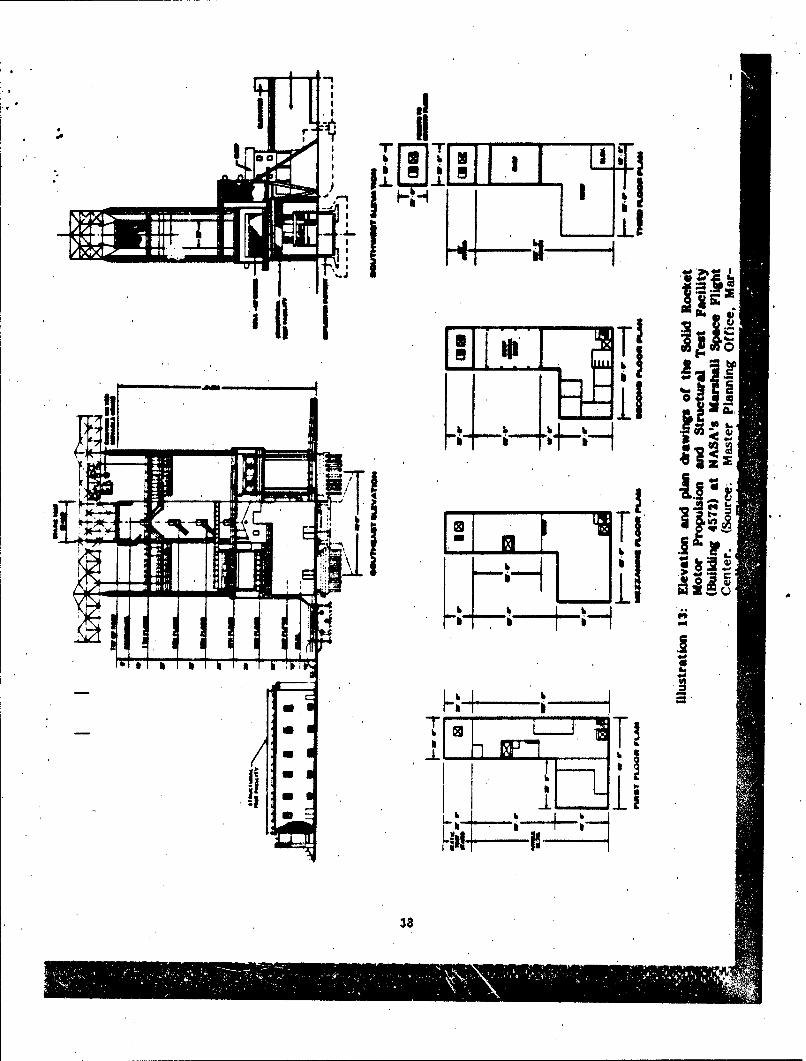
The Solid Rocket Motor Propulsion and Structural Test Facility (Building #4572).
constructed in 1957, is located in the East Test Area. Designed to gauge
the strength capabilities of various rocket motors, the facility was used in
the Saturn/Apollo program for testing the booster stage of the Saturn S-IB
vehicle and the F-1 engine of the booster stage of the Saturn S-IC vehicle.
It can structurally accommodate propulsion systems with thrust levels of up
to 1.8 million pounds. The twin rocket motor propulsion test stand Is 145'
high and 30' by 20' at the base. It is equipped with a 100-ton overhead
crane and a 45-ton gantry crane (Building #4573). Control and instrumentation
are provided by the East Area Blockhouse and Cable Tunnels (Building 44570);
with connections to the computer-controlled data acquisition system In the
Structures and Mechanics Laboratory. (Illustrations 12-13)
The Structures and Mechanics Laboratory (Building #4619) was built In 1959.
Test facilities include large high-bay and low-bay areas ror the static and
dynamic structural testing of large nnd small components of space vehicles
36
V% 1F4'

'I'I
37
S-16
' I I'
hil klJ T
____[!L38
I-!!•t ii -
L
38IK.. j' 4 iiL

or payloads. Test systems within the laboratory are linked to remote test
Wates by cable systems or by the Space Flight Center's comm•nication system.
A major component of the laboratory is the Structural Test Tower, which has
e 3 million pound universal testing machine with capacity for both lateral
and vertical load testing.
The Acoustic Model Engine Test Facility (Building #4540). built in 1964, tests
scale models of space vehicles. Small-scale liquid hydrogen and liquid oxygen
rocket engines with chamber pressure ratings of up to 5,000 psi can be fired
in the facility, which includes an Open Steel Test Stand Structure, a Mechanical
Preparation Shop (Building #4539), and an Electrical Control and Acoustic
Data Acquisition Center (Building #4541). A total of 148 acoustic measuring
stations are distributed over a large semi-circular blacktop area around the
test stand. Acoustic measuring stations are also located on the structure
itself. These measuring devices are used to record data during propulsion
systems tpsting.
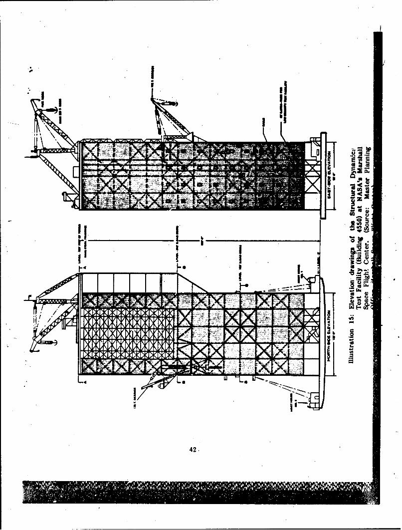
The Structural Dynamics Test Facility (Building #4550), built in 1964, can
test very large vehicles under dynamic load situations similar to those experi-
enced at launch and during flight. The vehicle rests on hydrodynamic supports
that provide a maximum of 6 degrees freedom of movement. Vibration loads
can be induced in the pitch, yaw, or longitudinal axis to obtain resonance
frequencies and bending modes. The performance of vertical mating features
between stages can also be investigated. The test stand is 360' high and
122' by 98' at the base. It has a maximum center bay size of 74' by 74',
and has a main derrick at the top of the structure capable of handling 200
39

torn at a 70' radius. The facility is connected by a cable tunnel to the east
wee Blockhouse (Building #4570). (ilustrations 14-15)
The Propulsion and Structural Test Facility (Building #4670), located in the
West Test Area, built in 1965, can accommodate propulsion systems testing
up to 12 million pounds thrust and was originally constructed to test the
Saturn S-IC booster stage engine at a thrust rating of 7.5 million pounds.
The facility Is capable of applying structural test loads to vehicles as long
as 1701and as large as 401in diameter. The test stand is 266'high and
stands on four concrete piers, each 48' by 48'. It has two derricks, a 200-ton
capacity derrick at the top of the structure and a 150-ton capacity derrick
at the 94' level. A wind barrier encloses the test stand and provides a
relatively protected environment as high as 130? above the base of the struc-
ture. Access platforms with working levels every ten feet extend to 112'
above the base of the structure. Hydraulic and pneumatic gas systems are
remotely controlled from the Test Control Center Blockhouse (Building #4674).-
Data acquisition' on 6,000 instrumentation channels is available at the block-
house. (illustrations 16-17)
The Barge Dock Facility (Building #8037) was constructed in 1966 for shipping
large space components that cannot be moved by conventional highway, raill,
or air transport The two concrete docks are located at the River Terminal
of Redstone Arsenal on the Tennessee River. They are specially designed to
accommodate the barges used to transport the Saturn I and Saturn V compo-
nents from Marshall Space Flight Center to the Kennedy Space Center at
Cape Canaveral, Florida. (Illustration 18)
/4

0412
41
.4.3
p 1p
Le a
I,42/

416
0.
43

-Cs)
V~ uU
443

I IL
0 I
'46
45

C4 L
46

.0 Q
IIm
//
47

The High Rey:olds Number Wind Tunnel Facility (Building #4775), built in
1968, can generate winds in the subeonic, transonic, and supersonic ranges up
to Mach 3.5. Its Reynolds number test capability in the critical transonic
range is higher by a factor of four than any other wind tunnel In the nation.
Primary components of the facility include a long constant ciameter supply
tube, a stilling chamber, six interchangeable nozzles, two interchangeable
test sections, a model support system, a diaphragm section, a receiver sphere,
and a 40-channel computer-controlled data acquisition system.
The Marshall Space Flight Center has numerous other laboratory buildings,
high-bay hangar-type facilities, and administrative buildings, some of which
were originally a part of the Huntsville ArsenaL The main administrative
area was built by NASA in 1963 and includes a 10-story building (Building 4200)
and two 6-story buildings (Buildings 4201-4202) that are situated on a hillside
overlooking the center's laboratories and, test stands. (Illustrations 19-20)
NOTES
1. U.S. Army Missile Command, Redstone Arsenal (Redstone Arsenal, Alabama:DARCOM, Installation and Activity Brochure, 1981), pp. 1-6; see alsoThis is DARCOM, p. 29.
2. Leo P. Brophy and George J. B. Fisher, The Chemical Warfare Service:anizing for War (Washington, D.C.: U.S. Army Office of Military
History, 1959). pp. 37 and 120-122.
3. Leo P. Brophy, Wyndhir. P. Niles, and Rexmond C. Cochrane, TheChemic,1 Warfare Service: From Laboratory to Field (Washingto-n,D.C.: U.S. Army Office of Military History, 1959), pp. 256-258, 277,and 343.
4. Helen Brents Joiner, The Redstone Arsenal Complex in the Pre-MissileEra: A History of Huntsville Arsenal, Gulf Chemical Warfare Depot,and Redstone Arsenal, 1941-1949 (Redstone Arsenal, Alabama: ArmyMissile Command, Historical Division, 1966), p. 4.
48
`101El0 1

5. Joiner, Pre-Missile Era, pp. 27-41; also U.S. Army Toxic and HazardousMaterials Agency, Ritallation Assessment of Redstone Arsenal, ReportNo. 118 (Aberdeen Proving Ground, Maryland), pp. I-.. - 11-5. Thedsiption of chemical munitions manufacture at Huntsville Arsenal inWorld War H that follows is taken from these sources
6. Joiner, Pre-Missile Era, pp. 69; 74.
7. Ibid, pp. 75-87.
8. Ibid• pp. 58-65.
9. Ibid, pp. 102-107; also Installation Assessment of Redstone Arsenal, p. 11-5.M description of production lines at Redstone Arsenal during World
War H that follows is taken from these sources.
10. Joiner, Pre-Missile Era, p. 101.
11. Ibid. pp. 123-128.
12. Ibid. pp. 132-133.
13. Helen Brents Joiner and Elizabeth C. Jolliff, The Redstone ArsenalComplex in Its Second Decade, 1950-1960 (Redstone Arsenal, Alabama:Army Missile Command, Historical Division, 1969), pp. 5-10; also ActivitBrochure, pp. 1-2. This brief summary of activities at Redstone •in--'from 1950 to the present is derived from these sources.
14. Department of Defense and National Aeronautics and Space Administration,"Army-NASA Transfer Plan," (Unpublished Agreement, December 11, 1952),pp. 1-4 and 11-17.
15. For pre-1960 Army activities in space see Ernst Stunlinger, "ArmyActivities in Space - A History," Institute of Radio Engineers, IRETransactions on Military Electronics, Vol. 49-4, No. 2-3, April-iuily 1960and Wernher von Braun, "The Redstone, Jupiter and Juno," in The Historyof Rocket Technology: Esnays on Research Development and Utility,ed. Eugene M. Ermme (Detroit: Wayne State, 1964), pp. 107-121. Seealso, Roger E. Bilstein, Stages to Saturn: A Technologcal History ofthe Apollo/Saturn Launch Vehicles (Washington, D.C.: NASA, 1980),pp. 23-56.
16. For a history of the Saturn program see Roger E. Bilstein, Stages toSaturn and David S. Akens, Saturn ruustrated Chronology: Saturn'sFi'rst Eleven Years, April 1957 through April 1968 (Huntsville, Alabama:MSFC, 1971).
17. The brief descriptions of major facilities at MSFC are taken from theMarshall Space Flight Center, Master Plan, 1982.
18. National Register Nomination for Redstone Test Stand, Redstone Arsenal,Madison County, Alabama, May 1976.
49
•t• ~ ~~~~ ~~ ,. • • •% i :

Chapter 3
PRESERVATION RECOMMENDATIONS
BACKGROUND
Army Regulation 420-40 requires that an historic preservation plan be developed
as an Integral part of each installation's planning and long ranp maintenance
and development schedulin. The purpose of such a program is to:
* Preserve historic properties to reflect the Army's role in historyand. its continuing eovt.,nrn for the protection of the nation's heritage.
* Implement historic preservation projects as an Integral pert of theinstallation's maintenance and construction programs.
0 Find adaptive uses for historic properties in order to maintaL. themas actively used facilities on the installation.
* Eliminate damage or destruction due to improper maintenance,repair, or use that may alter or destroy the significant elements ofany property.
0 Enhance the most historically significant areas of the installationthrough appropriate landscaping and conservation.
To meet these overall preservation objective., the general preservation recom-
mendations set forth below have been developed:
Category I Historic Properties
All Category I historic properties not currently listed on or nominated to the
National RegI.'r of Historic Places are assumed to be eligible for nomination
regardless of age. The following general preservation recommendations apply
to these properties:
50
soI

a) Raab Categor I historie property shuid be treated aIt it were
m the National Register. whether listed or mat rpete not
eiwretl listed shoul be momim~bted Category I historic properties
shoul rot be altered or demoishmed, All work on web properties
dolfl be performed in mmovdie with Seetlumion 18 ad6HIM of
the National HIstoric Preservation Act asamaabd In IMO, and the
regulatio. od the Advisoy CowUni for Historic Prwesrtlon (ACIUP)
as outlined in the "Proteetion of Historic, and Ciiturda Propertise
(36 CYR 00).
b) As Individul preser vation plan should be dmvlope and put MWt
effset for Samch ategory I flietorlc property. nki pem. shoul
delineate the appropriate restoration or aeservation props. to be
crrvied out for the property. It shulMbd icude a aniuuiemd!
repair sehedel mnd estimated initial and smwmm sosts. The preser-
vat ion plan shoul be appove by the State HIltoric FromsmtvlHn
Officer and the Advisory Coumeil In mceordemee with fth ave
* rferencd ACRP regaltlon. Until the hisors preeervation plan Is
put into ef feet. Category I historic properties d wli be maintained
in accordenee with the roeommendled approaches at the $mert
of the Dinterlor's Standards for Rehbiitation ud Revised Guideline
for Rehabilitating Historic Muidi2g and in eowanatotion with the
State Ristarid Preservation Officer.

4) lea Category I historic property should be documented 1 accor-
dose wi Historic Amerle &ld"Wp Suvey/Historle Americn
9FO~rW Record (HAN/HAR) DocuMentation Level U. and the
dinmentatim admitted for kwcmlon In the HABS/HAIR colleetions
in th Lhwy of CoW4uS When no adequate aueldtectwel drawings
elst for a Category I historic property, it should be documented in
mwith Dommentatio. L4el I of these standards. In
eases whee stan•d measued drawinp we uumble to rqcord ir-
alment featm of a property or techuologile proaem, Interpretive
spwings also simuld be prqee
Category II Histork ftqertie
All Categotry historic properties not currently listed on or nominated to
the National Register o( Historic Piaces we maumed to be esible for nomi-
nation rearlsso The following general preservation recommendations
apply to these properties:
a) Each Category fl historic property dsold be treated as If it were
oan the National Raltstdr, whether listed or not. Properties not
currently listed should be nominated. Category IU historic prop-
ertles thould not be altered or demolished. All work on such prop-
erties shall be performed in accordance with Sections 106 and
110(f) of the National Historic Preservation Act se amended In
19"0, and the regulations of the Advisory Coucil for Historic
Preservatkon (ACHP) as outlined in the "Protection of Historic and
Cultural Properties" (36 CFR a00).
S2

b) A Individual rervation plan should be developed and put into
effect for each Category i historic property. This plan uhould
dedlemt, the Pppropriate preservation or rehabilitation program to
be aterid out for the property or for those parts of the property
which contribute to its historical, architectural, or teodwological
importance. It should include a maintenance and repair schedule
mnd estimated Initial and annual costs. The preservatiom plan should
be approved by the State Historic Preservation Officer and the
Advisory Couez in accordance with the above referenced ACHP
reulatlons. Until .the historic preservation plan is put Into effect,
Category U histrie properties should be maintained In aecordance,
with the recommended approaches in the Secretary of the Interior's
Standards for Rehabilitation and Revised Guidelines for Rehabilitating
Historic Building 4 and in consultation with the State Historic
Preservation Officer.
E) ach Category 11 historic property should be documented In accor-
dwnc with Historic American Buildings Survey/Historic American
Engineering Record (HABS/HAER) Documentation Level IL and the
documentation submitted for inclusion in the HABS/HAER eoUee-
tions in the Library of Congrese.
Catefory MI Historic Properties
The following preservation recommendations apply to Category M historic
properties:
53

a) Category MI historic properties listed on or el 1.e for nomination
to the National Register as pert of a district thematic group
should be treated in accordance with Sections 06 and 110(f) of the
National Historic Preservation Act as amended In 1980, and the
regulations of the Advisory Council for Historic Preservation as
outlined in the "Protection of Historic and Cult al Properties"
(36 CFR 800). Such properties should not be demolished and their
facades, or those parts of the property that eaitribute to the
historical landscape, should be protected from eJor modifications.
Preservation plans should be developed f owwr inls of Category M
historic properties within a district or thematic group. The scope
of these plans should be limited to those ,parts of each property
that contribute to the district or group's Imporlanee. Until such
plans are put, into effect, these propeties should be maintained in
accordance with the recommended approaches I the Secretary of
the Interior's Standards for Rehabilitation and Revised Guidelines
for Rehabilitating Historic Buildings and in eos ultation with the
State Historic Preservation Officer.
b) Category M historic properties not listed on or eligible for nomina-
tion to the National Register as pert of a district or thematic
group should receive routine maintenance. Suchl properties should
not be demolished, and their facades, or those parts of the property
that contribute to the historical landscape, should be protected
from modifiaetion. If, the properties are unoc led, they should,
as a minimum, be maintained in stable conditio and prevented
from deteriorating.
54

HABS/HAER Documentation Level IV has been completed for all Category M
historic properties, and no additional documentation is required as long as
they are not endangered. Category III historic properties that are endangered
for operational or other reasons should be documented in accordance with
HABS/HAER Documentation Level 31, and submitted for inclusion in the
HABS/HAER collections Ln the Library of Congress. 7 Similar structures need
only be documented once.
CATEGORY I HISTORIC PROPERTIES
Redstone Rocket Test Stand (Building 4665)
Background and significance. The Redstone Rocket Test Stand, built In
1953 and operational until 1973, tested the modified Redstone Rocket
that carried the first American satellite into orbit in 1958. As noted in
Chapter 2, the test stand and its associated block house are listed on
the National Register of Historic Places. This property, although not
yet so years old, was listed on the National Register because it was
considered exceptionally significant to the development of the American
space program (see Chapter 2, Marshall Space Flight Center: Description
of Major Facilities, and Illustration 11). It is a Category I historic
structure because of Its strong association with the nation's space program.
Condition and potential adverse impact. The Redstone Rocket Test
Stand is protected and maintained as an historic structure at the arsenal.
and there are no current plans to alter or demolish this property.
55

* Preservation options. Refer to the general preservation weeommendations
at the beglining ot this chapter for Category I historic properties.
* CATEGORY 1U HISTORIC PROPERTIES
Neutral Bouyancy Simulator (Building 4705). 1955Solid Rocket Motor Propulsion and Structural Test Facility (Building 4572), 1957Structures and Mechanics Laboratory (Building 4419), 1959Acoustic Model Engine Test Facility (Building 4540), 1964Structural Dynamics Test Facility (Building 4550), 1964Propulsion and Structural Test Facility (Building 4670), 1965Hich R~nolds Number Wind Tunnel (Building 4775), 1968
* Backgroua d and significance. These facilities were all constructed at
NASA's Marshall Space Flight Center in support of the nation's space
program, and their functions we interrelated. Many we directly associ-
ated with the development of the Saturn Launch Vehicle, which was
used for the Apollo, Skylab, and Apollo-Soyus missions. (For a detailed
description of the individual structures, see Chapter 2, Marshall Space
Fligt Center: Description of Major Faeilities.) These properties do not
meet the eligibility criteria of the' National Register for buildings less
than 50 years old, but they should be reevaluated at a later date. All
are Category n historic properties because they have a direct association
with an important component of America's space program.
Condition and potential adverse impact. The properties are all currently
maintained by NASA. Some are being kept in "standby" condition, and
others are still actively used by NASA and other branches of the armed
services. There are no current plans to significantly alter or demolish
these properties.
56

Preservation options. Refer to the genral preservation recommendations
at the beglanint of this chapter for Category U properties not listed on
the National Register.
CATEGORY ITM HSTORIC PROPERTIES
Fire Station #3 (Building 7102)
Background and signfficance. Fire Station #3 is a military building with
unusual pretensions to style. It was constructed in 1942 as the main
fire station for the Redstone Ordnance Plant. The two-story wood
shipqI-sded building is derived from a standard World War 0I Army
building prototype but varies from the ,prototype through the employ-
ment of such distinctive architectural features as a curved entry bay.
and a five-story watch tower. The building served as a fire station
until recently and is now used as a general purpose administrative
building. The building does not meet the eligibility requirements for the
National Register of Historic Places, but is classified a Category M
historic property because it possesses local Importance as a work of
architecture. (flustration 21)
Condition and potential adverse impact. Fire Station #3 is currently in
good condition but is tentatively slated for, demolition, although no
definite demolition plans have been established.
Preservation options. The general preservation recommendations for
Category M] historic properties not listed on the National Register
advise against demolition and state that the facades of such structures
57

fe
'fa
J3.
49

should be protected from major modifications. If at all possible, an
adttive use should be sought for this building that will not alter 'ts
dttincUve architectural character. If the property must be demolished,
it should first be documented in accordance with HABS/HAER Documen-
tation Level Il and such documentation should then be submitted for
inclusion in the HABS/HAER collections of the Library of Congress.
Harris Residence (Bulding 8012)
* Background and signifleance. This house was constructed prior to military
acquisition of the present Redstone Arsenal site. Although the exact
date of original eonstruction is not known, records indicate that a
Mr. J. B. Harris combined two existing buildings, posibly slave quarters,
in 1927 to form one house. The house was sold to Sam Harris n 1937
and was renovated in 1938 with the addition of new siding and porches.
The house and property were purchased by the government in 1941.
The Lee House, a larger house built in 1818 and once located just to
the west of this residenace was recently moved from Its original location
off post to a Huntsville site. The Harris residence is a Category M
historic property because it is locally unique to its historic era and
contributes to an understanding of pre-military land use at the Redstone
Arsenal site. (mustration 22)
Condition and potential adverfz impact. The house is in good condition
and is presently being ade',uate!y maintained. There are no current
plans to alter or demcn.sh this property.
Preservation options. Refer to the general preservation recommendations
at the beginning of this chapter for Category ill historic properties.
59

. C4
60

NOTES
L. Army ReMuation 42-40, Historic Preservation (Headquarters, U.S. Army:• Washington, D.C., 15 April 0,11).
2. National Park Service, Secretary of the Interior's Standards for Rehabilitationand Revised Guidelines for Rehabilitating Historic Building& 1983 (Washington,D.C.: Preservation istance Division, National Park Service, 1983).
3. National Purk Servi , "Archeology and Historic Preservation; Secretaryof the Interior's St dards and Guidelines," Federal Register, Part IV,28 September 1983, . 44730-44734.
4. National Park Servie, Secretary of the Interior's Standards.
5. National Park Servie "Archeology and Historic Preservation."
6. National Park Servce, Secretary of the Interior's Standards.
7. National Park Service "Archeology and Historic Preservation."
1
A
/V
61
6
">1 &
Is*1,

BIBLIOGRAPHY
Redstone Arsenal
Armed Forces Chemical Association. The Chemical Warfare Service in WorldWar II. New York: Reinhold, 1948.
Bartholomew, Harland and Associates. Analysis of Existing Facilities/Environ-mental Assessment Report, Redstone Arsenal, Alabama. Memphis, TN:Author, 1977. Description of existing facilities with a brief summaryop the historical development of Arsenal.
Brophy, Leo P., Niles, Wyndham P., and Cochrane, Rexmond C., The ChemicalWarfare Service: From Laboratory to Field. Washington. DC.: U.S..Army Office of Military History, 1959.
Brophy, Leo P. and Fisher, George J. B. The Chemical Warfare Service:Organizing for War. Washington, D.C.: U.S. Army Office of MilitaryHistory, 1959.
Joiner, Helen Srents. The Redstone Arsenal Complex in the Pre-Missile Era:A History of Huntsflle Arsenal Gulf Chemical Warfare Depot, andRedstone Arsenal, 1941-1949. Redstone Arsenal, AL: Army MissileCommand, Historical Division, 1966. World War 9 and post-War historyof the three installations which comprise the present Redstone Arsenal.Bibliography included.
Joiner, Helen Brents and Jolliff, Elizabeth C. The Redstone Arsenal Complexin its Second Decade, 1950-1960. Redstone Arsenal, AL: Army MissileCommand, Historical Division, 1969. Description of rocket programslisted chronologically.
Jolliff, Elizabeth C. History of the U.S. Army Missile Command, 1962-1977.Redstone Arsenal, AL: HQ MICOM, Historical Division, 1979.History of the programs at Redstone in the 1960's.
National Register of Historic Places. Redstone Rocket Test Stand, 1976.
Thomas, Prentice M. Jr. Cultural Resources Investigations at RedstoneArsenal, Madison County, Alabama. New World Research, Inc., 1980.Evaluation of cultural resources at Redstone with brief developmentalhistory and land-use patterns.
Thompson, Harry C. and Mayo, Lida. The Ordnance Department: Procurementand Supply. Washington, D.C.: U.S. Army Office of Military History,1960.
U.S. Army Missile Command. Redstone Arsenal. Redstone Arsenal, AL:DARCOM, Installation and Activity Brochure, 1981.
/

U.S. Army Toxic and Hazardous Materials Agency. Installation Assessmentof Redstone Arsenal, Report No. 118. Aberdeen Proving Ground, MD:Author, 1977.
Marshall Space Flight Center
Akens, Davis S. Saturn Illustrated Chronology: Saturn's First Eleven Years,April 1957 thrioujfhA[Iil 1968. Huntsville, AL: MSFC, 1971, 5th ed.HisitFory oSaturn program with over 400 illustrations, many of testfacilities at MSFC.
Bilstein, Roger E. Stages to Saturn: A Technologcal Histo of the Apollo/Saturn Launch Vehicles. Was ington, D.C.: NASA, 1980. Illustratedofficial history of Saturn program with excellent notes and "Sourcesand Research Materials."
Brooks, Courtney G., Grimwood, James M., and Swenson, Lloyd S. Jr. Chariotsfor 1ollo: A Histo of Manned Lunar Scacecraft. Washington, DCNASA, 1979. Official history of Apolo development, references to MSFC.
Depart.-ient of Defense and National Aeronautics and Space Administration."Army-NASA Transfer Plan," unpublished agreement, December 11, 1959.DOD/NASA in-house ak-reement, MSFC Library.
Emme, Eugene M. The History of Rocket Technology: Essays on ResearchDevelopment and Utility. Detroit: Wayne State, 1964. Backgroundhistory for U.S. rockets and missiles.
George C. Marshall Space Flight Center. "Apollo-Saturn " Huntsville, AL:MSFC, NASA Fact Sheet, 1980. Apollo-Saturn highlights in 7 pages.
George C. Marshall Space Flight Center. Facilities Data Book. 1982. Majorbuildings at MSFC, photos and reduced m&awings(e ev-atins, floor plans,site plans).
George C. Marshall Space Flight Center. Master Plan. 1982. Illustratedpresentation format of mission, capabilities and facilities.
George C. Marshall Space Flight Center. Real Property Inventory. 1983.Buildings in numerical order with dates of construction.
Stuhlinger, Ernst. "Army Activities in Space - A History," Institute ofRadio Engineers, IRE Transactions on Military Electronics, Vol. 49-4,No. 2-3, April-July 1960. Eye-witness account of Army rocket andmissile programs in 1950s.
63