Embed Size (px)
Citation preview
3x'mical R e p x t No. 3-3
bY
V. R. Parfitt and A . C. Eringen
July 1966
Subroitted to
National Aeronautics axxi Space Administration
Under Contract rrClm-Ugg

THE GENERAL TECHNOLOGY CORPORATION i s engaged in the application of science and scientific methods to industrial problems.
Because of i t s unique structure, the Corporation is in a position to supply the services of outstanding scientists having university positions. These men work in teams as consultants to solve prob- lems undertaken by the Corporation. The following are typical examples of the fields of study in which the staff has been actively engaged:
Elasticity Plates and Shells
Plasticity Magnetohydrodynamics
Viscoelasticity Aerodynamics
Seismic Waves Electromagnetics
Thermoelasticity Systems Analysis
Porous Media Instrumentation
Linear Programming Ordnance
Noise and Random Vibrations
Inquiries for the arrangements of exploratory discussions of problems may be directed to either of the following ofkes:
Research and Development: 203 So. 9th St. Lafayette, Indiana Phone: 742-0570
Business Ofice: 474 Summit Street Elgin, Illinois Phone: 695-1 600
1';

i
A b s t r s c t
This paper is coneerne2 with the investigation of the effect
of rcicrostructure i n the solution of sevefal problem of wave propa-
cpticr!.
space and their ref lect ions from a stress free f l a t surface are
Sstudiec',.
wave5 can e x i s t traveling a t four d i s t i n c t speeds, three of which
disappear below a c r i t i c a l frequency dependent upon 'the character
of the medium. fieflection l a w s and amplitude r a t io s are presented
f o r three spec i f ic problems.
The prcl-etion of plane waves i n a micropolar e l a s t i c half-
It has been foun2 +ht i n a micropolor e l a s t i c so l id s i x
I
I I
1
I
INTRODUCTION
"he c lass ica l e l a e t i c i t y theory- is believed t o be inadequate fo r
the treatment of deformations and motions of a material possessing &ran-
u l a r structure. In p a r t i c u l a r , the a f f e c t of granular, or microstructure,
b e c m s important i n transmitting waves of mall wavelength andlor high - frequency. When the wavelength is cmparable w i t h the average grain size
the motion of the grains m u s t be taken into account.
new ty-pes of waves not encountered in the c lass ica l theory.
This introduces
The present paper is an attempt to s t u d y the e f fec t of microstructure
i n the solution of' several problems concerning wave propagations.
thie end w e w e the theory of micropolar e l a s t i c i t y developed i n a series
of papers by Eringen and his coworkers [l] to [3].
To
The basic difference between the theory of micropolar e l a s t i c i t y
and that of c lass ica l e l a s t i c i t y is the introduction of an independent
microrotation vector.
be obtained from a knowledge of the three crpnponents of the displacement
vector. I n micropolar e l a s t i c i ty , i n addition, we must have knowlew
of the three camponents of the microrotation vec tor .
of the general theory show that such solids can support couple streseee
and may be affected by the spin inertia.
In c lass ica l e l a e t i c i t y all other quantit ies can
'Ihe developllent
In Chapter 1 we present a xesuae of the basic equations of micro-
polar e l a s t i c i t y necessary for the analyeis of wlive motion.
derivation aad diacussian of these equations were given in 1964 by
Eringen and Suhubl [l], [2].
mlcmpohr elasticity and studied various qussldone on stability and
uniqueness of the solutions of s t a t i c and a;vnSmic boundary value problem.
A ccmrplete
Recently Eringen [3] has lPcapitulated the
.

_____~ ~
General ?kchn010gy Corporation 2
Using tbis theory ne detexmlne the t y p s and speeds of plane waves in an
. infinite micropolar e l a s t i c solid. New dispersive microrotational waves
are found In addition t o those similar to the c la s s i ca l ones. The die-
pemion relatione - discussed i n detail resulting i n several inequalit ies
among the consti tutive coefficients.
for several of these new waves below vhlch .they degenerate t o a vibratory
motion of the medium.
We also find a cutoff frequency
Chapter 2 is devoted to a discuesian of re f lec t ion of plane, longi-
tudinal dieplacement waves frosn a f la t free surface.
and amplitude ratios are obtained.
i n detai l and a few typical curves are sketched.
program is carried out f o r the reflection of coupled transverse shear
and rnicroroUitiona.3. waves and i n Chapter 4 f o r those of longitudinal
m i c r o r o t a t i o ~ ~ ~ ~ wave&.
limiting case when the incident waves are grazing parallel t o the boundary.
Reflection angles
Certain special case8 are studied
In Chapter 3 the same
chapters 2 and 4 -0 contain an -is of the
. The f i r s t l imiting analysis in Chapter 2 is similar to that presented by
Coodier and Bishop [ 4 ] for c lass ica l e l a s t i c waves (see also Ewing, Jar-
detskcy and Press [ 51). An experimental ver i f icat ion of the f3ndings of
Goodier and Bishop has not been made though I(bLsky 161 states that the
generation of a transverse wave when a longitudinal wave ~il118 parallel
t o a free surface has been observed experimentally.
we also use a limiting analysis due to F. C. Roesler [7 ] the results of
which in the c lass ica l case have been verif ied experimentally by D. G.
Chrietie [ 81.
In Chapters 2 and 4
The content of Chapters 2, 3 and 4 is believed to be new.

General ?rechnology Corporation .
c
c
This chapter is concerned with the discussion of the propagation
of plane waves in a microelastic sol id .
theory of micropolar e l a s t i c i t y (21, 131. are also to be found i n an independent paper by Pal'mov [9] and one by
Mindlin [lo].
first of these papely;, it differs frm the second and, i n f ac t , some of
the results are i n d i r ec t contradiction.
The analysis is based on Eringen's
k i e f accounts on the subject
While the present work has certein similarities to the
Basic Equations
mingen's theory of micropolar e l a s t i c i t y is based upon t f ie follow-
ing equations:
Balance of momentum:
Balance of manent of momentum:
m + E t + p(lk - j gk) = 0 ..
rk , r kLr Ir
Conservation of energy:
p i - t ( v - € v ) + % , v kl L,k htr r 1,k
C o n s t i t u t i v e equations:
General Yeckinologs~ Corporation
- ”
c
- -
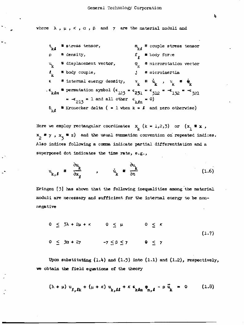
where A , p , h‘ , a , f3 and 7 are the material nociuli and
t ii stress tensor, B couple stress tensor
p =: densi ty , Id
Io body force
S nicrorotation vector f 4
% 5 displacement vector, yk I body couple, ,j E microinertia k E internal eiiergy density, Vk E p J Vk * i;:
132 -€ 321 = - €
123 ‘231 = €312 . E ab permutation symbol ( E kern
= -E E l a n d a l l other E 0 0 ) 213 Urn
C Kronecker delta ( 0 1 when k = 8 and zero otherwise) %E
\ (k = w , 3 ) or (x x p 1 Here we employ rec&ngular coordinates
x
A l s o indices following 8 curnma indicate partial differentiazion and a
superposed dot indicates the time rate, e .g . ,
y , x3 i i) and the usual sunmation convention on’repeatec! indices. 2
Eringen [3] has shown that the following inequalities among’the material
moduli are necessary and sufficient for the internal energy to be non-
negative
Upon substitutfsg (1.4) and (1.5) into (1.1) and (1.2)y respectively,
we obtain the f i e l d equations of the theory

Cemral Techn010gy Corporation
I -
. 5
where we have also s e t = k = 0 . The boundary conditions on tmctions and couples a t a point of the
surface 3 of the body v+ 3 are expressed as
%Lnk = I
where t and m are respectively the surface tractions and surface
couples prescribed on 3" and n is the exterior normal to 3 . W i t h the use of (1.4) and (1.5) these read
1 a
k
It is cowenient to express the f i e l d equations (1.8) and (1.9) in
vector form
2 2 2 2 +c)v(v*pJ-(c + c ) v x ( v x y ) + c v x q , - jf (1.12) .c (c; 3 2 3 3
where
2 K
1 P 2 P 3 P
2
c2 0 u c2 c E c = -
c4 PJ 5 P J
2
0 J PJ a+B w * @ - * - c3 K
m - 7 c2 (1.14)

General Tkchnology Corporatian
. We now decmpose the vectors 1p and 9 into scalar and vector
c
pc+--^z:ti& : D E m
6
cp v r p + v x p 4
Introduction of these potentials into equations (1.12) and (1.13) yields
.. 2 3
- c V x & + ~ ] = 0
2 .. 2 2 2 - 2 - G[(c4 + c 5 ) v cp - a* cp - 61 - v x [ c4 v x (v x 2)
I
2 2 0
- b J v x u + 2 u o 2.3.: 0 (1.18)
These equations =ray be expressed as
where the scalar potential a and the vector potential & are defined
as tbe appropriate quantities in the brackets. In particular, we can
mite, [u, P* 521,
whelp E is definedby

. General !kchn010gy Corporation
7
r
In the pmsent case B 0 , hence = 0 60 that
Thus the necessary and sufficient conditions that equations (1.17) and
(1.18) be satisfied are that each qyantity enclosed in brackets be iden-
t ica l ly zero. Hence
-
L. 2 2 2 - 1 3
(c + c ) 3 u = u
.. ( c ; + c 2 ) a , + c 2 0 x 2 = Q 3 3
.. 2 2 2 2 v g - 2 w ( + + w V X J L = 2 - =4 0
It may be observed that equations (1.20) and (1.21) are uncoupled for the
scalar potentials and (p while equations (1.22) and (1.23) consti-
tute a coupled system for the detelmiaation of the vector potentials u and 2.
Plane Waves in In f in i t e Medium --- . Plane waves advancing in the positive direction of the unit vector
y may be elcpressed as
where a b are cmplex constants, & , a may be complex constant

General Technology Corporation 8
vectors, v is the phase velocity, k is the wave nuriber and is the
posit ion vector. ‘laus
i n which 1 is the wavelength and & , J , & are the unit Cartesian
base vectors.
Substi tution of (1.24) in to (1.20) y i e l d s
2 2 2 -1 1 1 3
v a c + c = ( A + 2 V + K ) P
Hence, if v is t o be real we must have 1
h + 2 p + U - > 0
F’rm equation (1.15) w e obtain for the displacement vector
(1.26)
which is i n the direct ion of propagation. Hence these uaves represent
the counterpart of the classical d i l a t a t iona l waves. For K = 3 .. (1.25) gives the c l a s s i ca l wave speed. Since the displacemat is in-the dime-
t ion of propagation for the waves traveling a t speed v, we shaL W i g - A
nate them longitudinal displacement waves. - Turhing our a t ten t ion nar to equation (1.21), for th6 speed of
propagation v , we obtain 2
Introducing the angular frequency w by

General Technology Corporrrtlon
equation (1.27) may be written as
Equation (1.29) s h m that the speed of propagation v depends on 2
the frequency w . Eence these mves are dispersive. I n par t icular 2
if w > Ji? wo end 2
then v is real and the microrotation waves exist. The microrotation
vector cp is given by 2
-
This expmssion also shows that the microrotation vector points in the
direction of propagation.
c a l e las t i c i ty theory and to distinguish it fran other microrotstional
This is a new wave not encountered in class$-
waves we shall c a l l it a longitudinal microrotational wave. - If w = J 2 w = w the wave ha^ infinite velocity v 'as given
2 o c 2 by equation (1.29) and the wave does not exist.
2 When w <%r2 o equation (1.29) shows that the speed v2 is .
2 0 negative and v is pure imaginary, tha t is ,
2
v = t iIvJ 2
~
General %?chnology Corporation
10
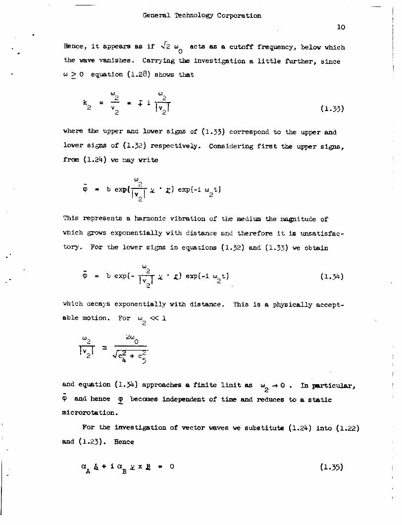
Hence, it appears as i f $2 w 0 acts as 8 cutoff frequency, below which
the wave vanishes.
w - > 0 equation (1.28) show that
Carrying the investigation a l i t t l e further, since
w 2
W 2 k = - 2
V 2
where the upper and lower signs of (1.33) correspond to the upper and
lower si- of (1.32) respectively.
frm (1.24) we may w r i t e
Considering f i r s t the upper si*,
I
This represents a harmonic vibration of' t h e medium the ryLgnitude of
which grows exponentially w i t h ciistance and therefore it is unsatisfac-
tory.
I
For the lower signs i n equations (1.32) and (1 .33) we obtain
which aecays exponentially w i t h distance.
able motion. For w << 1 2
This is 8 p r n i c a l l y accept-
I
2 W
T;;T=- 5
0 2 W
0 2 W
2 W
T;;T=- 5
and equation (1.9) approaches a f ini te l i m i t as w 2 3 0 . In psr t icular ,
(p and hence L cp becomes independent of time and reduces to a static
microrotation.
For the investigation of vector waves we substi tute (1.24) into (1.22) l
and (1.23). Hence
a & + i a B y x a - 0 A (1.35)

~
f
I - where
2 3
, a = k c 2 2 2 2
B 01 = k (V - c2 - c ~ )
A
(1.36)
(1.37)
Forming the scalar products of equations (1.35) and (1.36) w i t h y
it becomes apparent that
provicred a f 0 , ag # 0 , 8, & and B l i e in a carrrnon plane whose unit noma1 is y . Solving for
0 and B f 0 . Hence both vectors A B
from equation (1.36) we get '
0 , = - i - - y x &
n
bB (1.39)
from which we conclude that the three vectors y , & ana 8 ELR rnutudly
perpendicular.
Equation (1.39) shows t h a t if 4 P' 0 then I!J 0 making both
and & vanish. Thus there would be no coupled waves propae ted . A
similar analysis from equation (1.55) holds for
waves cannot vanish unless they do so simultaneously, hence they are
S 0 . These two
truly coupled waves.
If Q , and hence 2 , are non-zero, the second terms of (1.15)1
and (1.16) will show that and cp are n o m 1 to esch other and to
the direction of propagation y . Hence they are transverse vayes. We
cal l the wave associated w i t h Q 8 tsansverse displacement wave and tfke
one associa-d w i t h &J a transverse microrotational wave. - 'Ihe transverse
.c 1

I -
~
General l k c h m l o ~ Corporation i i 1
I2
displacement vave is similar to the c l s s s i c s l 8hxs.r wave and will reduce to
it in the limit of classical elasticity. The appearance of a transveree
I
I microrotatiod wave coupled w i t h it is new. I
I (1.39) into (1.35) w i t h the use of (1.9) for & Q gives I
The velocitleer of propagation of these waves are determined by carrying
where
2 0
2 w a = (l--)
2 w 2 2
0 2 0 2
w 2w 2
b = - [ C E + c2(1 - -) + c (1 - -11 w 2 3 u
2 2 2 a ( v ) + b v + c = 0 .( 1.40)
(1.41)
2 2 2 c = c ( c + e )
4 2 3
Equation (1.40) is a quadratic eqyation in v2 which yields two dist inct
speeds of propagation. These waves are dispersive. In the c lass ica l
case the roots of (1.40) are v = 2 0 , v = tm of which the last one
is the speed of shear v8ve8 given in ths c lass ica l theory. In order to
have two real velocities both roots of equation (1.40) for v m u s t be
positive.
2
he positive mote of equation (1.40) are
v = [-I. 2a (’b +4KGjI1’* 3
1/2 1 v4 = [- 28 (-b -Jb2 - 4ac)l
By use of (1.41) we can eventually obtain
(1.42)
(1.43)

Gene- Technology Corporation
2
3 4 ,2
I ~
! 13
which show that the d i 6 C r i ~ & ~ % n t is greater th8n or equal to zero since
K > O and y > o
t h a t i f G ) > W a
a < 0 . Since the
- - C
v is real f o r w 3
by (1.7) and w - > W . > O , I f w = o then a = O , a n d f i . n a U y i f w < w , numerator of Y is always posit ive we conclude that
> w , i n f in i t e f o r w = w , and imaginary w < w .
Fram equation (1.41)1 we see
C C
3
C C C
The detailed analysis i n the next section shows that v remains real
and f i n i t e for a l l w . Hence, t h i e c r i t i c a l frequency w - d 2 o is
again a cutoff fmquency f o r one o f the wave speeds.
4 r
C 0
In sunmary of t h i s section, we find that there are s i x waves travel-
ing a t four d i s t inc t speed8 i n an infinite micropolar e la s t i c solid:
(a) A longitu6inal displacement wave a t speed v similar t o the ala- 1 - t a t iona l wave of the c lass ica l theory; (b) a longitudinal microrotation
wave traveling with a speed v9 with its microrotation vector i n the - L
direct ion of propagation.
i f the frequency w
w =J2 oo
This motion exists as a progressive wave o w d
is larger than the c r i t i c a l c i r c u l a r frequency
&law this frequency the mve degenerates into sinusoidal C
vibrations decaying w i t h distance frcxn the source.
four are two sets of waves cmpoaed of tvo wave6 each.
a t speed v and the other at speed Y
verse displacenrent wave coupled vith a transverse microrotational wave.
An analysis similar to that for the longitudinal microrotation wave shows
( c ) The remaining
One s e t propegates
EBch se t -cons is t s of a trans- - 3 4 - - - -
* An investigationwasmadeallowing w 2 < 0 and w imaginary. Aophysi-
caUy acceptable progmssive wave solutions w e r e obtained. This is not surprising, however, since the basic theory does not contain a m e c h a n i s m for internal f r ic t ion .

Generrrl Tt?chnology Corporation 14
I - - ~L
I -
t - -
that the set of' coupled uaves traveling at speed v
w ;. cieSeur~aiiilg iaLa a ii:i?'ca;ice deca3h.g sfii-srfc'al ;-iIzmti~z
otherwise.
(1.42) and (1.43) is carried out in the next section.
exist only if 3
C
A more detailed analysis of the dispereion relations (l.29),
Analysis - of Dispersion Relations
In this sect ion we study the dependence of wave speeds on frequency.
The wave speed v is constant, thus we only need to study the characters
of v , and then v and v 1
4 . 2 3 According to equation (1.29) we have
2 2
V %
A sketch of
is imply a
88 S h o M
For
2 V
in
(1.45)
2 (1.45) is shown i n Fig . 1.1. The sketch of v- versuB w
reflection of the figure about the line x
Figure 1.2 since x and w m e mutually
the wave velocities v and v we have 3 4 - 2
C 1 2 2 2 2 3
I + c + c - (c* + -)x '3,4 2 0 - x ) (=2 3 4 2
z = 1 ( w = w =J2 "0)
C
lpciprocal.
I 2 2 2 2 2 2
3 4 + - J[(c4-c2-cJ) + ( c 2 2 ) x f ? + 2 2 2c c x) (1.46)
w h e r e the upper sign refers to v2 and the lower one to v2 in the above 3 4 and in vbat follows.
wavelength values
Ietting x -t 0 (o + 0 ) (1.46) yields the short
2 2 = c + c
2 2 2 3 - c4 v4 2 3 *
For x + Q (w + 0) the long vavelength U t a are obtained .

* L
~~
General 'lkchnologg Corporation
2 2 -
- C
2
/ I
Figure 1.1. 2
.Sketch of v versus x . 2
I
w +uJ i W P W C
I I I I I
2 2
Figure 1.2. Sketch of Y versus w .

General %chnology Corporation 16
L
L 2 a 2 1 2 Y, = 0 7 v4 = c3 + r, c,
6 2
If we allow W = W then x = 1 and tbe denaninator of eqmtion C
c ’ 5 = -= *Or (1.46) vanishes. This leads to v = f o r w > w
w < u and 3
C
2 2 2 2 2 2 2)-*l lin v4 - c (c + c ) (c + 4 2 3 4 2
x - b l
(1.49)
2 2 2 We see tbat if c = 0 then v = c - E , the c lsss ica l speed, inall
thne cases. If c = 0 also, then $ = 0 and we have the complete
cLassical situation.
3 2 4 2 P
4 3
Comparing our knowledge of v 2 and Y 2 at th is point ve see that
arises as to whether or not they intersect. If v4 L (GO) > v 2 (a) then
3 4 2 at w = w v
finite values In the l i m i t a8 w tends to infinity. Hence, the question
I s infinite and ? is finite and.they both approach c 3 4
3 the curves intersect, Otbend8e they do not. Assuming the curves inter-
sec t then there exists an w euch that v ~ = v4 . Using equations (1.42) and (1.43) we find that we m u s t have
cue8ion of equation (1.44) we concluded that
2 2
b2 - 4ac = 0 . In an earlier dis-
b2 - 4 a c - > 0 e J 1 w
the equal B i g n being in the Uit 88 w -0 . diction and the curves & not interrrect for a q finite w .
Hence we reach a; contra-
Tbey my, however, approach the same l i m i t 88 @.+a Thio meam Y 2 (a) = v 2 (a)
3 4 2 2 2 2 2
or c = c + c . In general then v (w) > y,(w) , except possibly at
infinitywfitre the equal 8ign holds, hence v > v for w > w which
lllgans
4 2 3 3 2 2 C 3 - 4

~ -~
General Technology Corporation
I- - 2 2 > c + c 2
= 4 - 2 3
Using equations (1.14) we obtain an additional inequality among the con-
st i tut ive coefficients
(1.51) Y - > p + K J -
2 2
We can continue this -is by taklng the limits of the deriva-
which m u s t be satiefied to have a consistent solution for v and v 3 4 -
2 2 3 b tives of v and v etc. The results of all these canputstions are
incorporated i n Figure 1.3. 2 4 Next ve investigate the relative msgnitudes of v at u 0 0 , ,
u = u ,. and w = 0 . Ewtim (1.47)2 and show -d2ately i;
thnt If c2 + 0 3
Likewise, ccanperison of equa-ions (1.47) and (1.49) shows t h t 2
2 2 k 4 c
To can- v (0) and v ( w ) wemuet campan eqGtions (1.48) and
or (1.49).
V&O) 5 vk(wc) . 2 1 2 2 2
FroDll the inequality (1.3) we see that c2 + cJ 5 c4 2 2 Consequently we conclude that
I
2 2 2 4 - 4 c - 4 v ( 0 ) < v ( w ) < v (a)
and show tbeae result0 in Figure 1.3.
canparison of equations (1.25) and (1.47) vith t ~ ~ e a id or (1.14) 2
shows tbat

. L
Genenil Technology Corponrtion I
18 I
+
+ ucu 0
8 U 3
3
0

2 2 71 ’. ‘p4
General Technology Corporation 19
(1.55)
2 2 1 1 3
A similar comparison of (1.25) and (1.47) for v and v is inconclu-
sive. If
> h + Z ! p + K J -
then
2 2 3 - 1
v > 9 w > oc
(1.56)
(1.57)
2 2 2 3 1
is constant there exists a fre-
However, if‘ the opposite is true then
increases for decreasing w and v:
v (a) < v , and since v,(w)
I 2 2 C 3 1
quency w , say w* , where w < w* < Q) such t ha t v = v . That is,
w*
sign and solving for w . Then we conclude that
is found by equating equation (1.25) to equation (1.b6) with the upper .
2 2 1 3 -
v > v w < w < w * - C
b) > w* 2 2 1 - 3 - v > v
Since the reflection problem considered in the later chapters do
not e i w r l t l y involve longitudinal displacement w4-s and longitu-
dinal microrotation warn a ccinpwi~<w of speeds v and v is not
nectsmry . 1 2
Call- 2
and v 2 2 ’ v3 4 . We now txamiac the relative m3gnltudes of v2
parieon of Figures 1.2 and 1.3 show at infinity

General Technology Corporation 20
and hence v2 w i l l be greater than v 2 for u > w if v 2 2 > v st 2 3 C 2 3 2/ 2 r&i w - ? w v3i v2 C
w t w . To thls end we mtennine the l i m i t of C
(x + 1) . A t x = 1 this ratio simplifies to
2 Y
2 1 2 2 2-1 + - c )(c4 + cs) - - = ( = 4 2 2 3
3
2 Y
(1.60)
2 2 2 2 3 5 2 3
Nov if we are to brrve v > v then c >' c2 fram which (1.14) shaws
t h a t the inequality
1
2 c r + p > - j K ( 1.61)
among the constitutive coefficients must be s a t i s f i e d . If the opposite
of (1.61) is s a t i s f i e d then there exists a frequency ww such that
vz(w)(() = v2(W") when w < w- < Q . In this case v 2 2 > v when 3 - 2 2 2c 3 w < u < u w and v < v when w * * < w . - 3 - 2 - C
Briefly, if inequality (1.61) is sat i s f ied then
w < w 2 2 2 v > v > v 2 3 4 C
holds. If the opposite i n e q d i t y is satisfied there exists w- such
that either
2 2 3 - 2 - 4 v > v 2 > v
or
2 2 2 v > v > v 2 - 3 - 4
( 1.62)
We bave cavered all poaeiblc case8 vithout definite knowledge of the

I - .
General Technology Corporation
relative valuee of the constitutive coefficients. These relations am
v i t a l to the analyses in the m i n i n g chapters.

General Technology Corpo=.ation
22
I - - I
Fondation
This chapter is devoted to the study of re f lec t ion of a longitudinal
displacement plane wave a t 8 stmsa Pree plane surface of infinite length.
The free surface is taken to be the x,y-plaae w i t h posit ive z pointing
i n t o the medium, Figure 2.1.
direction of a u n i t vector y is reflected a t the z L: 0 plane. To
s a t i s f y the boundary conditions on tractions and couples a t the boundary
An incident p l a n e wave advancing in the
1’
it is necessary to postulate the existence of reflected waves in three
d i s t i n c t directions, % , +, and y4 . These an (1) a longitudinal d i s p h u n e n t wave having speed v in the direction y2 a t a n a n & l e
1 8 (2) at speed v a transverse d i spkemen t wave coupled with a
transverse microrotational wave in the direction of yt , and (3) a simi-
direction at speed v if w > w . lar se t of cowled waves in the
If w < u th i s laet set of waves degenerates to a vibration of the
medium a6 dlscuesed in Chapter 1, thus we 8 8 8 1 ~ ~ w > w in tbe remainder
of the chapter.
2 ’ 4
5 3 C
C
C
If the x = 0 plane is so selected as t o mabe the incident U-
placement vector remain i n the y, z plane then the ref lected wave6 a t
the fme surface z - 0 will a280 have their displacement fields in
the same plane.
su f f i c i en t for the underetanding of the three-dimensional problem. The
nonvaniehing components of the potentials are given by
Thus the study of the problem in two-dimemions is

General Technology Corporation
23
Fi=we 2.1. Ref lec t ion of a longi tudinal displacement wave.
X
/ =
I z
Figure 2.2. Boundary conditions on surface z = 0 .

24
- u - a
% =
% = where
summed. Tbe coefficients and ~JX? related to each other by e-
quation (1.39) so that
w = kv , (a at 1, 2) , f3 = 3, 4) and the repeated indices are not
n
$ * vith 8 similar equation for
U i t h the boundary surface z - 0 being free froan tractions and
couples we must have t = m - 0 . Thus through (l.lO), (1.11) and the e 4
fact that u1 - cp2 - (pj = 0 we get
which must be satisfied at z = 0 for all y and t 'Ibe positive
directions of surface tractions, couple and the exterlor normal a m
shown in Figure 2.2.

Technology Corporation 25
I ’
I -
! .
Basic solution - The solution of 8 reflection problem consists or determining kbe
amplitudes and directions of the reflected waves when a known vave is
incident on the boundary.
conditions (2.3), (2.4) and (2.5) together w i t h equation (2.2) and a
similar equation for Bq todeterninethethreeamplitudes a
and A i n b n n s o f a .
The potentials (2.1) are used in the boundary
2 ’ A3x
4x 1 The potentials (2.1) satis0 the boundary condition (2.3) a t z = 0
if
and
= *4 w = w 1 3
k v = k v k v = k v 1 3 y 12y 3 3Y 4 4Y
2 2 2 2 halls1 + ( ~ w K ) a k2? + ha k + ( 2 p t ~ ) a2klv2z
1 1 l z 2 1
Since the incident wave is in tfrc y,z-plane v = 0 and (2.8) yield8 Ix
V - v - v = o 4x 21. 3x
showing that all the waves
t ion (2.6) s t a t e s that su
w i l l allow us to determine
for a given incident angle
we can w r i t e (2.7) a8
l ie in a y,z-plane as assunrd earUer.
the frequencies are equal and equation (2.7)
the angles of reflection of the various waves
containedin v . U s i n g t b e r e l a t i o n w = k v
Equa-
lY

- .
C v4 V 1 3
V 1
V
26
(2 .lo)
where c
front along the free surface.
writ ten
has a sinple physical meaning, m e l y the speed of the wave-
~n terms of the angles, (2.10) nay be
sharing e = e . 2 1
Equation (2.3) is one of the three needed to determine the qmpli-
and A4d’al . tude ratios a /a The other tvo boundary
conditions (2.4) and (2.5) give the two additional equatioas needed.
three equations BO obtained are
2 1 ’ A3x/al The
V 2 42 - ( 2 p t - K ) v - x = O
3x 4x
( 2 W ) V v 8 + ( 2 W K ) V v a lyh1 2y 22 2
2 2 2
2 V
4Y V
2 0 2 2 a: 2 -I& - 42,
V
(2.14) 2w
2 v 4x 32 4y =4J v 4 v p - 2) - c ][v (1 - 2) - A 4 4
w4 w 3x 3
and %2 = -a 1
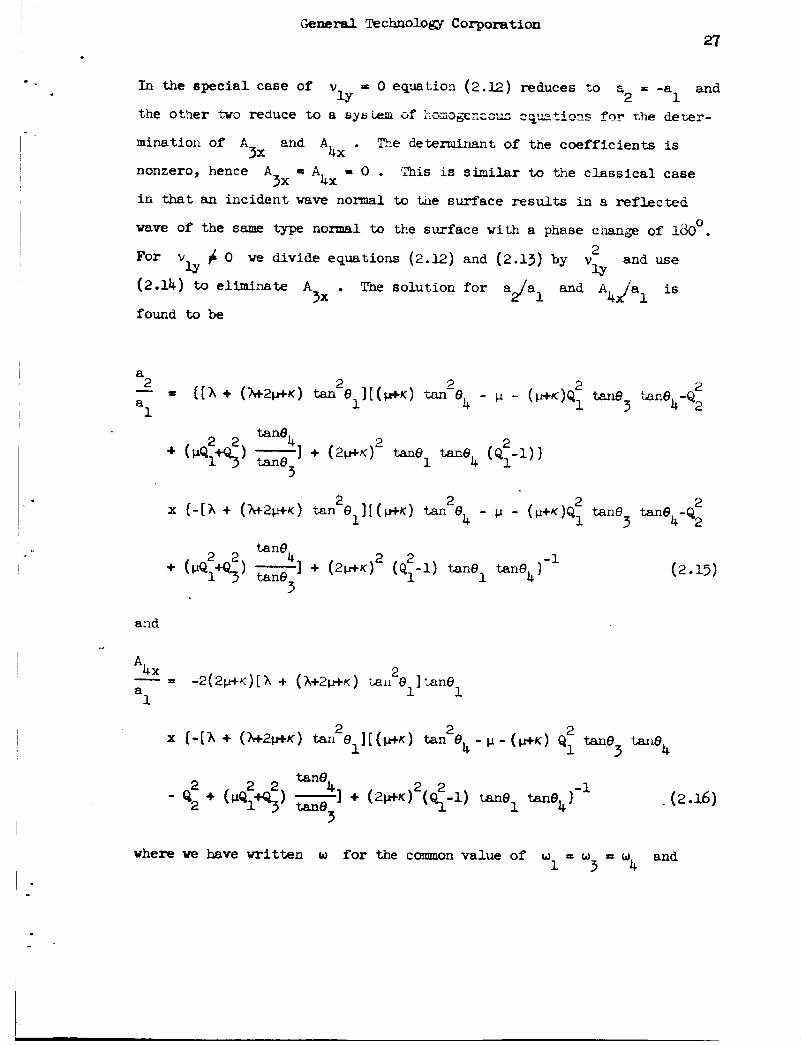
I n the special case of
the other two reduce t o a sys i em of ~ L G ~ g c z c ~ * ~ :~!tic??s f n r T.he deter-
mination of A and A * Tze deterninant of the coeff ic ients is
nonzero, hence A - A - 0 . 'This is similar to the c la s s i ca l case
i n that an incident wave n o m 1 to tne surface results in a r e f l e c t e d
= 0 equation (2.12) reduces to
3x 4x
3x 4x
wave of the same type normal t o the surface with a phase change of 180 0 . 2 For v 4 0 w e divide equations (2.12) and (2.13) by v and use
lY lY (2.14) to eliminate A . Tne solution f o r A 4 9 a l is 3x found to be
x ( - [ A + ( & ~ C + K ) t a n 2 e p ~ + + ~ ) tan 2 e& - p - ( ~ + K ) Q , 2 tan6 tan6 -Q 2 3 4 2
2 2 taneh
3
2 2 1 + ( ~ H K ) (Ql-l) tanel tan6 1- l + (PQ1+Q3) tane 4
and I
*4x - - 2 ( 2 , ~ ) [ h + ( A + ~ c ~ + K ) &tail 2 e I t ~ m 8 ~
a 1 1
x { - [A i ( h t - 2 ~ ~ ) t an 2 e ~[(WK) tan 2 O4 - p - ( W K ) Q, 2 tan6 t-a116~ 1 3
(2.16)
where ye have writ ten w for the common value of w = w and 1 3-4
l -
& n e r d Technology Corporation 28 i
l - i -
I -
i -
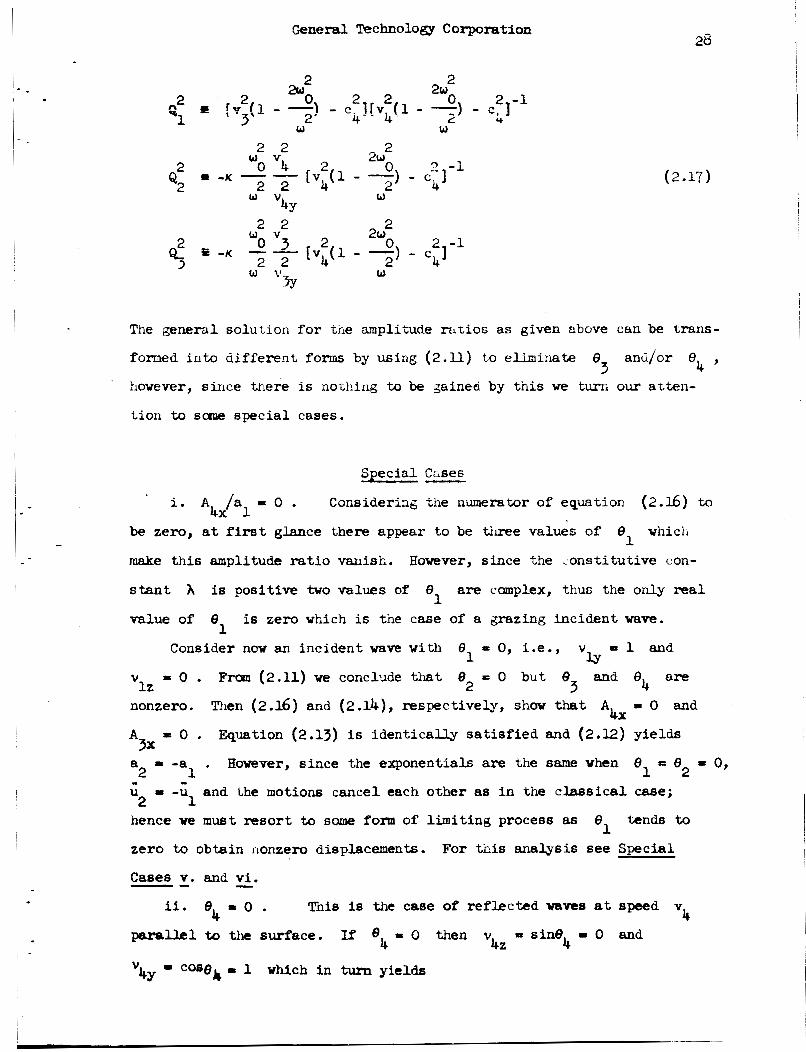
2 0 2 -1
2w 2 2 a: 2 2 * i ! V 3 ( l - -1 - e. l[v, ( 1 - 2) - c , ] -1 2 4 - 4 U
2 2 2
2 2
2 2 2
2 2
2 w 2
Q2 -K --
w 4Y
w v
2w
w %
The generdl solution for t n e amplitude m t i o s as given above can be trans-
4 ’ fomed i n t o d i f fe ren t forms by us ing ( 2 . l l ) t o eliminate 8 anti/or 8 3
however, since trlere is nothing to be gained by t h i s we turn our atten-
t ion to scene special cases.
Special C~ses - * i. A /a = 0 . Considering the numerator of equation (2.Ib) to 4x 1
be zero, a t f irst glance there appear to be three values of
make t h i s amplitude r a t i o vanish.
s t a n t A is posit ive two values of 8 are complex, thus the only real
value of 8
8 vhich 1
However, since the <onst i tut ive con-
1 is zero which is the case of a grazing incident wave.
1 Consider now an incident wave w i t h 8 = 0, i.e., v P 1 and
1 w v = 0 . Frcm (2.11) we conclude that 8 = 0 but 8 and 8 are lz 2 3 4
nonzero. Then (2.l6) and (2.14), respectively, show that A = 0 and 4x A
a - -a . However, since the exponentials are the same when 8 = 8 = 0,
- 0 . Quat ion (2.13) is ident ical ly sa t i s f i ed and (2.12) yields 3x
2 1 1 2 - -: and the motions cancel each other as i n the classical case; 2 1
hence we m u s t resort to same fonn of l imit ing process as
zero to obtain llonzem displacements.
Cases v. and vi .
tends to
For t h i s analysis see Special
- -- 4 ii. e4 = 0 . This is the case of reflected waves at speed v
paral-hl to the surface. If e4 = 0 then v = sine - 0 and 4z 4

General Technology Corporation 29
V 1 = cose I - 4
1 V V ly
from (2 .lo). Then equation (1.35) shows v > v giving cos8 > 1 1 4 1 and 8 is imaginary. Since our incident wave angle is betveen
0' 0
1 and 90 and real t h i s means we cannot have a ref lected graziw wave
4 . w i t h speed v
iii. 8 = 0 . In this caee 8 will be real if v > v since 3 1 3 1
V 1
cos9 I - 3
1 V
Two possibi l i t ies i n ttis case are respectively &ven by (1.57) and (1.56)
corresponding to the inequalit ies
Hence v > v and 8 is real if (1.57) or (1.58) is satisfied. 3 - 1 1 1 U s i n g (2.14) and (2.17) we c a n mite
1
m e 4 A
2 A - Q1G 4x
3 3x (2.18)
Multiplying the numerator and denaninator of (2.15) by tan6 /tan0
l e t t i n g 8 = 0 we get a /a = -1 . If we ca r ry (2.l.6) in to (2.18) end
and 3 4
3 2 1 let e = o ~ @ t
3
A
a 3r = -2 tane1(2p + K ) ( V + 1
Also through (2.18) i n t h i s l imi t A 4 h 1 = 0 when 8 f 0 . these results take the forms
For 8 - 0 4 3

I * - .
I
I -
.
~~
General Technology Corporation 30
a P -1 2
1
- a
4 , cos6 = - 3
V V 1
3 - a 1 V 4 V
= 0 , COS$* = - A4x
1
where the angle (3;
f o r a set of re f lec ted grazing waves at s y e d
is given by (2.11) . This completes the solut ion 2
v 3
The angle of incidence and the anplitude r a t io s given by (2.19) 2
are plot ted against w f o r varioiis vaaces of pa,wieters. Tile micro-
i n e r t i a j is estimated on the basis of a polycrystall ine Liietal wf;ose
* Grain s i ze is approximately 0.0025 inciies. Based on this r p i n s i z e the - 6 2
lover limit f o r j is abou t10 i n . for one w i n . For a microvolwne
o r lo00 grains we get an average value of j approximately 10 in. . We also assume p to be the mass density of steel, approximately
-3 2
2 -4 1b.-sec. - in . . It is 'assumed trjat K is small campared to h and p and that
A = p . We fur ther assme that CY , f3 and 7 are smal l conipared to
A and p , and i n par t icular , to sknplify the calculations we let
a! = 8 = y such that tne i n e q d i t y (1.51) is sa t i s f i ed .
W i t h these assumptions we use (2.19) along w i t h several d i f fe ren t
values of the parameter y / j h . The results are sketched i n Figures 2.3,
2.4 and 2.5. The curves in general show that the amplitude r a t i o
A J P l increases f o r increasing y / j h
that the amplitude r a t i o for a fixed y / J h is f i n i t e for large w and
becomes more nemtive f o r decreasing
of w i n which case i t quickly turns to zero. The curve remains
If K { 0 Figure 2.5 s h m
w unti l ye reach the neighborhood 2 C

Figure 2 . 3 . Bcisent angle 8 vs. frequency w i t h K I A = 0.m 1
0
0 d
f
2 Circular Frequency w w -+=
Y - = 3 Jh
-2 c
Figure 2.4. Amplitude

. 32
-. t
l -
I I I

General T!echnology corporatian
33
/ - - '
i - .
c
bounded f o r a l l finite values of the parameter 7 / j h ; hawever, 88 t h i s
parameter goes to in f in i ty the en t i r e amplitude ratlo curve rnovelt uut
tuwards inf ini ty . Physically, however, t h i e r a t i o is bounded s ince
y / h << 1 and j cannot equal zero since it is a function of grain size.
For j = 0 the character of our d i f f e ren t i a l equation changes so that
no wave solution ex i s t s .
iv . 8 is compler. In t h e previous case we have seen t i l a t as
is decreased fram 90 tarards 0 tke angle 8 of the re f lec ted
wave8 a t speed v decreases from 90 to 0 faster than 8 . In parti-
c i i a r e goes to zero a t e = 6" > o . AS is decreased below
t he c r i t i c a l angle 8" equation ( 2 . U ) show tbt (v /v 1 case > 1
and hence cos8 > 1 and 8 is cmphx. Subst i tut ion of
0 0 3
3 0 0
3 1
3 1 1
1 2 3 1 1
3 3
A
and cos6 into t h e potent ia l (2.1) w i t h p = 3 yields 3 2
(2.20)
( 2 21)
from which we see that the transverse waves a t speed v become a dis-
turbance propagating along the boundary at the speed 3
whose amplitude decays erponentiaUy w i t h distance z i n t o the &dim.
This is similar to the c l a s s i c a l case for an incident shear wave, but
differs i n the f a c t that a p l is no longer equal to one and AkJ'al
is no longer zero. Thus 88 8 is decreased beyond e* we have a
disturbance along the surface, a ref lected longitudinal wave a t speed 1 1
V and angle el , and a set of coupled transverse waves a t speed v 1 4

General Technology corporatlan 54
andangle 6 . With 8 c m p l e x t h e amplitude ratios a a 4 3 2L and are also canplex ind icatbg phase sh i f t s i n the reflected waves.
A t a first glance one is tempted to c a l l the exponentially decaying
surface wave a Rayleigh wave, On c loser examination, huuever, we see
that the wave speed var ies continuously from G = v when 8 "; and
v = v when 8 = 0 as we decrease e whereas a Rayleigh vaye has a 3 1 -
1 1 1 fixed speed. The incident wave forces the surface disturbance t o travel
a t a specif ied speed.
An independent approach can also be made by s e t t i n g a = 0 i n 1 (2.12) to (2.14). The three homogeneous equations nay possess nonzero
solutions f o r a , A and A, i f the determinant of the coeff ic ients
is zero. Tils leads t o a polynomial equation f o r the deternination of'
t he Rayleigh wave apeeds.
2 3x 4X
The problem was studied by Suhubi and Eringen
E23
v. F i r s t l imi t ing case f o r a zero angle of incidence. We now
study the problem of re f lec t ion when the angle of incidence
t o zero. From the previous case we know that 8 is complex unless
tends
3 w > w* and (1.p) is satisfied i n which case 8 is mal and is given
2 3 - . The limiting angle 8 is l i k e w i s e given by v 3 h 4 by cos8 =
3 case = v /V fzwn (2.n) with case = 1 . The angle e is equal to
and tends to zero also. Thus the general solut ion reduces to zero 4 4 1 3 1 2
motion as 8 goes t o zero. 1
To obtain a nonzero solution we present b r i e f l y an analysis s imi la r
to the one given by Goodier and Bishop [ 4 ] f o r the c l a s s i ca l case.
bas ic procedure is to expand the angle re la t ions (2.11) i n powers of
The
8 (TaylOr'8 series about 8 = 0) and Similarly f o r the! general solut ion
given by (2.15) and (2.16). A f t e r v a r d s the product a 8 is asaumed
to remain f i n i t e aa 8 tends to zero. The resulting solut ion is a
nonzero motion.
t e n t i a l
1 1
11
1 Carrying out t h i s process we find for the scalar po-

General 'pechnology Corporetitm
I - 1 -
- tj* 9 G = G + u = -ale12(g + ik z) exp[ik (y-v t)] + o(s;)
1 2 1 1 1
where
2 1 1/2
V
(7 - 1) v4
35
(2.23j
If we allow 6 to go t o zero and a to tend to i n f in i ty such 1 1 t h a t -2a 9 i a = constant then equation (2.23) w i l l yield a nonzero
1 1 0 motion of the ydium. The f i r s t term i n (2.23) is constant and could
represent the incident wave; however, t i e second term which represents
the-reflected longitudinal wave is proportional t o the distance z . This is physically unacceptable because it becomes unbounded for in-
creasing z . Also, as 8 tends to zem the incident wave and the
reflected wave of the same type become indistinguishable from each other
physically.
1
Even though this theory has its f l a w it does predict a
ref lected shear wave coupled w i t h a microrotational wave a t speed v 4 - vi. Second limiting process for a zero angle of incidence.
In the case where 8
physically meaningpul rrolution following a method si_milnr to the one
used by Roerler [7] for the clsseical case.
tanrls to zero it may be possible to obtain a 1
The barric equations (2.12) and (2.13) a m solved for the ratios

Gcned Technology Corporation
where (2.14) has again been wed to elininate A . A s 8 tends to
zero the first r a t i o has a finite l i m i t different from zero vhlle the 3x 1
second one tends to zero. Experinentally the measurable quantity for
1 the longitudinal asplacement waves is a + a but neither a nor a
alone since a t 8 = 0 the waves are indistinguishable. We then conclude
that A is finite and given by equation (2.27) since we & S 6 W the
physically mbasurable quantity a + al to be fini- . For finite A
2 1 2
1
4x
4x 2 (2.26) show that a - a must be i n f i n i t e . Hence if a + a is 2 1 1 2 - f in i t e and a - a is i n f i n i t e they must be of opposite signs and both
infinite in magnitude. 2 1
The potentials (2.1) for the dlsphceclents then
have the values
- - 3 - u + u = (a + a2) exp[ikl(y - vlt) l 1 2 1
and
4 = A4x exp[ik 4 (y cog0 4 + z sine4 - v4t)] (2 028)
is given by (2.11) as 04 3 where A ‘ is given by (2.25) and the angle
4x
4 cos0 = -
1
V
4 V

General 'pechnology Corporation
- - 8 .
1
This solut ion satisfies the wave equations and appropriate boundary
conc i i i iw aid has been r.rrified e.,xprL~r?+nl$v frlr rlassical e l m t i c i t y
[ 93. In the present case it predicts a s e t of coupled waves a t speed
and angle 8 in addition to the longitudinal wave a t speed v
along the surface. A s pointed out previously, under cer ta in conditions
we may h v e re f lec ted a set of coupled waves a t speed v
8 also.
v4 4 1
and angle 3
3
EEEE2 I n summarizing t h e analysis of t h i s chapter, we have seen t h a t an
Incident longitudinal disi;lac-ntweve a t a p b n e stmss free boundary,
i n general, r e f l e c t s as a wave of the same type and two sets of coupled
transverse waves. &e set of codpled waves t ravels 'a t speed v i n the
dime t ion
y,+ . For noma1 incidence
speed v and v vanish and the only wave reflected normal t o the
surface is a wave of the same type as t h e incident one.
incidence is decreased from 90
(2.11), (2.14), (2.15) and (2.l6).
3 and the other set travels a t screed v i n tile direct ion 4
0 (el = 90 ) it w a 6 shown that the waves at 5
3 . 4 As the angle of
0 the general solut ion is given by equations --
* The general solut ion prevails u n t i l 8 - is reached a t which 1 -
time 8 = 0 , 0 , and A = 0 . A t this angle of incidence (2 .19)
shows that we have a surface motion t ravel ing a t speed v and a re- 3 4x
3 flectedlongitudinalwaveatspeed v andangle 8 - = e* . AS 1 2 - % 1
0 8, I s decressed f'rm e: t o 0 the angle 8, become6 complex. The
A 2
interpretation here is that we have re f lec ted i n t o the medium
dins1 wave a t angle 8 and a set of coupled transverse waves 1
a longitu-
a t speed
as well as a s e t of' coupled surface wave8 decaying e4 and angle v4 with depth i n t o the medium and traveling a t a speed
Fina l ly as
c w h e r e v > c > v 3 - - 1' tends to zero we have t h e l imit ing solut ion of case v i .

1 9 i
- .
CrnPTER 3
REFLECTION OF CoUPLED "SVERSE SHEAR AMD
MICROROTkTIONAL WhVES
Formulation
In this chapter we study t h e ref lect ion of a set of coupled trans-
The presentation v4
v4
verse shear and microrotational waves a t speed
pmille2.s +&at, of Chapter 2 fo r the longitudinal wave.
t o be i n the direc-
t h e boundary conditions will be s a t i s f i e d if w e have ref lected
Assuming the set of coupled waves a t speed
t ion y1 a longitudinal displacement wave a t speed v and direction y2 and the 1 two sets of coupled waves a t speeds v and v as shown in Figure 3.1 .
For the incident waves w e have the potent ia ls 3 4
and for the ref lected waves
where E 3,4 and not summed. The coefficien'.s of % % and

General Technology Corporation
N
39

* .
I - -
~anersl Technology Corporation
40
are =lated to the respective
to (2 .2) . Assuming A known we determine the ampiimcies
and A
coefficient through equatiomsimilar
n "2 ' '3x Ix
4x The potentials (3.1) and (3.2) must satisfy the three conditions
(2.3) to (2 .5) for a l l y and t and z = 0 . These three equations
enable us
and A 4 d A h as w e l l 88 the angles of reflection.
to solve for the three mplitude ratios
Basic Solution - Substitution o r the potentials (3.1) and ( 3 . 2 ) into the boundary
conditiors (2.3) to (2.5) shows that tncy are sat i s f ied if
V V 1 3 case = - COS^ , case = - COS@
1 4 1 v4 2 v e4 = el ?
and
A 3x (2pK)k2 v v - 2 2 a2
+ (2w)v2zlkl A- - 3 3Y 32 Ah Ix
(3.3)
and

Excluding the special case of v = 0 which w i l l be studied later, ly
t 2 ~ t b e equations (3.4) to (3.6) y i e l d for the amplitude ratios
w h e r e < i e given by (2.17) and 1
2 2
w lY w v
~~
General Technology Corporation ~ 42
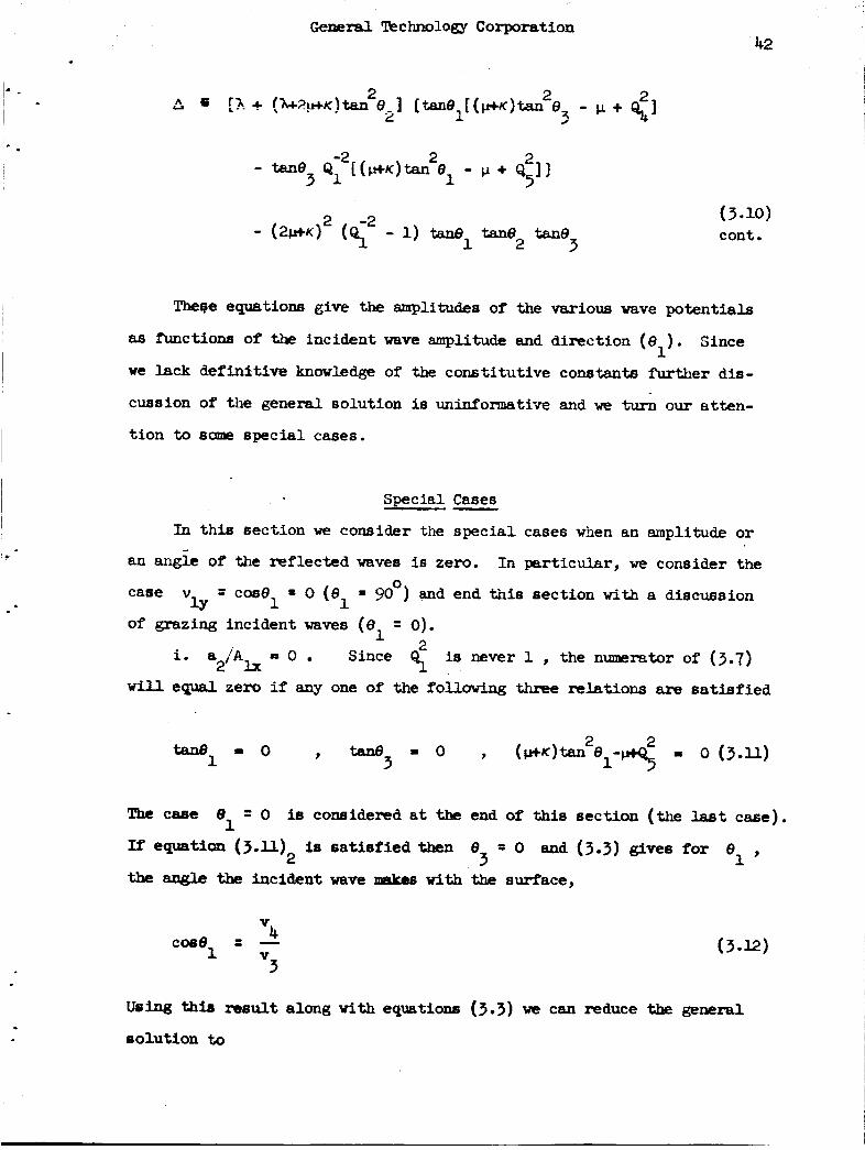
The$e equations give the amplitudes of the various wave potent ia ls
88 Arnctions of tfre incident wave amplitude and direction (8 ) . we lack defini t ive knowledge of the const i tut ive constants further dis-
cussion of the general solution is uninformative and we turn our a t t en -
Since 1
t ion to sane special cases.
Special Cases - In t h i s section we consider the spec ia l cases when an amplitude or
an an& of the reflected waves is zero. In par t icular , we consider the 0 = cos6 = 0 (el = 90 ) and end t h i s section with a discussion
1 of grazing incident waves ( e = 0).
1 Since < is never 1 the numerator of (3.7) a2’Alx - *
will equal zero if any one of the following thm~ relations are satisfied
The case 8 2 0 is conaidered a t the end of t h i s sect ion (the last case). 1
If equation ( 3 . u ) IS s a t i s f i e d then e = o and (3.3) gives for e 2 3 1 ’
the an@ the incident wave makm w i t h the surface,
Using ai13 result along w i t h equations (3.3) we can reduce the general
~oiut1011 to
- -
I - *
General Technology Corporation 43
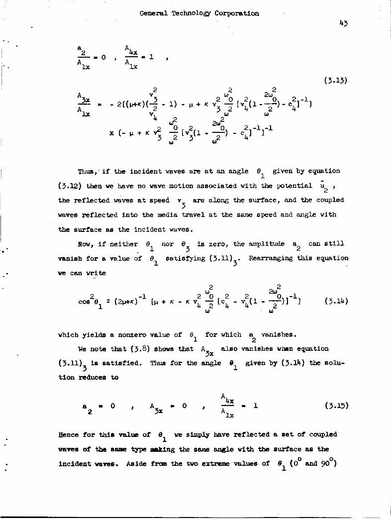
2 20
2
2 2
3 2 3 2 wo 2 0
A V - 3x x - 2 ( ( p + K ) ( ~ - 1) - p + K V - [Vb(l--)- W
2w *lx
Thus,-if the incident waves are at an angle 8 given by equation 1
( 3 . 1 2 ) then we have no wave motion associated with ih potent ia l
the reflected waves at speed v are along the surface, and the coupled
waves reflected into the media travel a t the same speed and angle with
2 '
3
the surface as the incictent wdves.
War, if neither 8 nor 8 is zero, the amplitude a can sti l l 1 3 2 vanish for a value of 8 satisfying (3.11) Rearranging this equation
1 3 - we can write
2 2
(3.14) 2 -1 2 w 0 2 2 &o -1
COB e = (2p.t~) (p + K - K v - [c4 - v,+(1 - ~ 1 1 1 . w
4 2 W
1
which yields a nonzero value of €I1 for which a vanishes. 2
We note that (3.8) shows that A also vanishes w b n equation 3x
(3 .U) is sat i s f ied . Thus for the angle given by (3.14) the eolu- 3
t lon reduces to
Eence for W e value of 8
mvcs of the same Qpe making the 8- angle w i t h the surface a8 the
incident waree.
we simply have reflected a set of coupled 1
from the t w o extreme values of el (0" and mol

General !kchnology Corporation
\ - - . the only remaining special case is when 6 2 = 0 .
V.
I. -
b COS e = -
1 1 V
(3.16)
I S k 8 S v4 as given by equation (3.7)
than v1 . However, the angle 8 is complex for values of the frequency
between w and w* (see (1.581) since v is greater than v and C 3 1
cos6 f as given by ( 3 . 3 ) . The amplitude ratios, which do not
This is a real angle since
- 3
2.
3 reduce greatly, are given by the general solution and are seen to be
complex since 9 is complex. 3
Thus for an incident set of waves at the tingle 8 given by (3.16) 1
the reflected waves along the surface consist of two superposed sets.
One set travels at speed c = v
This set corresponds to the-potentials # and 5 . wave a t speed v corresponding to potential cQ , has no decay factor,
although any f’urthcrr decrease of‘ 8
a t speed c , less than v . There will also be a set of reflected
waves of the 8ame trpe as the incident waves.
a phase-shift since the amplitude ratio A
and decays with depth into the medium.
The other surface 1
1 ’ L
would result in a decaying wave 1
1 These waves w i l l undergo
ViU be complex. 4JAlx
1 lii. 8 .I 90° . Since we divided our equations by v = cos0 1 ly
earlier, we aov consider separately the situation if
Then v 3 -1 and (3.3) shows that v = v = v L. 0 and hence
V = v = v = 1 . Using these relations in (3 .4) , (3.5) and (3 .6 )
v = 0 (el 90°). lY lz 5 3Y 4Y
22 3z 42 we obtain three equations which yield amplitude ratios
S O 2 a - Ix A
(3.17)
and
ceneral Technology Corporation
45
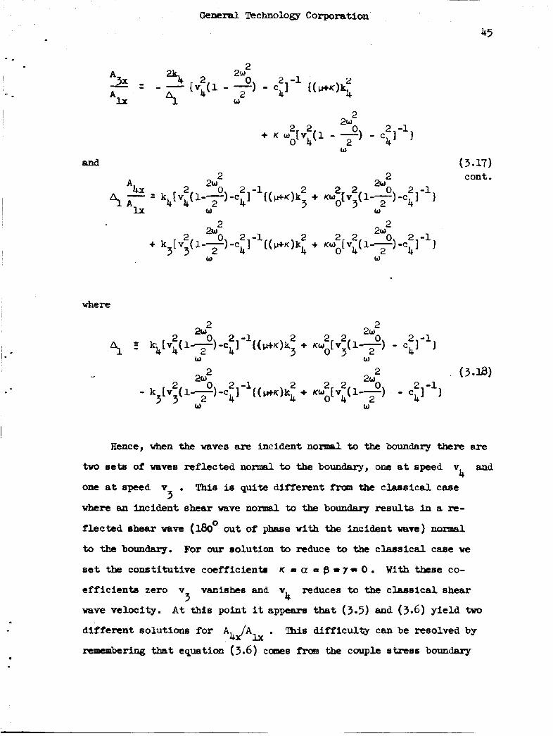
2 2w
0 c2, -l f ( *K)$ A 3x % 2 - - [v4(l - --) - Ix 4 W
- = A
2 2w + K W 2 2 [V (1 - 2) 0 - C 4 1 2 -1 1 W
0 4
(3.17)
where
Hence, when the waves lncid,ent normal to the boundary there are
two sets of waves reflected n o d to the boundary, one at speed v and
one at speed Y . This is quite different fram the classical case
where an incident shear wave normal to the boundary results in a re-
flected shear vave (l&* out of phase with the incident wave) noma1
to the boundary.
set the constitutive caf f ic ienta
eff ic ients zero v vanishes and v reduces to the classical shear
wave velocity.
different solutions for A
remembering tbst equation ( 3 . 6 ) canes frm the couple etress boundary
4
3
For our solution to reduce to tbe clsrrsical case we
K - a = p - I = 0 . With these co-
3 4 A t U s point it appearer that (3.5) and (3 .6 ) y i e l d two
. This difficulty can be resolved by 4 d A h

General mchn01ogY Corporation 46
condition (2.5) which vanishes identically if a I) f3 I y P 0 . equation (3.6) is nonexistent and the solution does indeed reciuce:
c lass ica l one.
Thus
*&e
iv. el = o . An analysis similar to case v i of Chapter 1 shows
is finite and we are to have a and A finite 4% 2 3x
that i f Ah + A
3 then Akx - A m u s t be inf ini te . However, both angles 8 and 8
8re cmplex and we would have the surface shear wave represented by A
+ A
by a2 c = Vk
Ix 2
Ix and the t w o exponentially decaying surface motions repmsented
Since all of these waves travel a t the 8- speed 4x
A3x . it appeans that separation of these e f fec ts experimentally uould
be e x t w n t l y di f f icu l t .
see a transverse suriace wave a t speed v represented by A + A . Hence i t i s postulated tha t we would indeed
4 Ix 4x
Summarizing, we'see that i n general an incident set of mupled waves
a t speed v results i n the reflection of two sets of coupled waves,
and the other a t speed v and a longitudinal one set a t speed displacement wave a t speed v , a s a m h g o > w . If w < w the
1 C C
set of reflected waves a t a p e d v degenerates to a vibration of the 3
medium and we have essent ia l ly the classical cme.
4
v4 3 '
0 If w > w and 8 = 90 we have two sets of coupled waves reflected
C 1 is decreased t k reflected waves move
equals the crit ical . value given by As
normel to the boundary.
toward tbe surface and when 8
(3.12) e3 = 0 , the langitudinal vave vanishes, the set of waves at
speed v becomes parallel to the surface, and reflected inta the medium ,
A8 the set of coupled waves a t speed v similar to tbe incident wave8
and in phase w i t h them. As 8 is decreased beyond this value the
surface wares associated with
mcdlum, and reflected into the mxiium we have a longftudinal wave a t
1
3 4
1 decay with depth into the 3 and 5
6peed v
speed v
and a set of coupled waves similar to the incident waves a t
The amplitude ratios becane complex since 8 is complex 1
4 - 3

iP . I
I - 1 -
General ’Pechnol~gy Corporation
47
Indicating that the reflected waves have a phase shift. With Further
decrease of 8 we reach another value such that e = w . -The oniy
waves mr lec ted in to the m e d i u m nov are the coupled waves of the same
type a8 the incident waves.
1 2
Further decrease of 8 malres 8 complex as w e l l as 8 , hence 1 2 3
the waves associated with and % all t rave l a t speed c and
decay w i t h depth in to the medium. then show
is the complex conjugate of the denornine that the numerator of A
and the waves ref lected into the nedium ator. a his mew IA
2+J Equations (3.9) and (3.10) 3
d A J X
4 A X l = are of the same type and magnitude a8 the incident waves but w i t h a
along v4 When 8 = 0 we predict a set of cou2led waves a t speed
w i t h the expnen t i a l ly decaying surface motion associated with the 1
. Experimentally these suprposed motions 2 ’ 1 L j a n d 5 potent ia ls 3
appear to be inseparable.
given by (3.14) the amplitude a 2
vanishes. The numerator of (3.9) s e t equal to zero may give possible
values of 8 such that A would equal zero. In order to make an
analysis of this case meaningful we m u s t wait f o r an e-xperimental deter-
mination of the consti tutive coefficients involved.
A t Ehe value of the angle
1 4 X
t

- -
Genersl Technology Corporation
48
c m m 4
REPIXTION OF A LQNGI'IVDINAL
M IC ROROTATIONAL WAVE
Fo mula ti on
This chapter is devoted t o the study of the ref lect ion of a longi-
tudinalmicrorotational wave a t speed v
a ha l f space. We r eca l l that this wave has its microrotation vector
pa ra l l e l t o the direction of propagation. Since this wave degenerates
into a distance decaying vibration f o r w < w the inciaent wave and
its ref lect ions disappear. Thus the analysis nust be confined to the
a t a stress free surface of 2
C
range w > w . C
A t first glance it appears that an incident longituciinal microrota-
t i o a wave may r e f l e c t only another miye of the sane 'type a t the same
angle. This would be sinilar t o the ref lect ion of horizontally polarized
waves in the classical case. Ihrfortunately, this ane r e f l e c b d wave
satisfies Go boundary conditions only.
An investigation show that horizontally polarized transverse dis-
placement waves with par t i c l e motions only i n the x-direction w i l l
praride a set of reflected wave8 consistznt with the boundary conditions.
Coupled with each tranrivense displacement wave there ie a traneverse
microrotational wave whoee microrotation vector is perpendicular to the
direct ion of propagation and in this case the x axis also.
of re f lec t ion ie self-coneistent without the necessity of having a re-
f lec ted longitudinal displacement wave at speed v - Hence when we
discuss longitudinrnl waves we mean the 1ongitudina.l microrotation wave
a t speed v and when we mention coupled waves we mean the transverse
This picture
1
2

General ~ c h n o l o g y Corporatian 49
* . microrotation wave coupled w i t h the transverse displacement wave at speed
v and a similar set a t speed v 4 ' 3 I n order that the transverse dieplac-nt waves have par t ic le motion
In the x-direction only U must equal zero. Moreover ve have y & = 0
or v A + v A = 0 It follow that the vector potent ia l must have
the form
X
Y Y z =
V
Thus we see that the potent ia l actually has only one coeff ic ient
A . Also it was s h m that the coefficient 2 of the potent ia l p is given interas of by Y
Since both
parallel to
b for the 2
y and & l i e i n the y,z plane w e see that will be
the x-axis. Thus there are three unknown coefficients:
ref lected longitudinal microrotational wave, A for the - 3Y
coupled waves a t speed v , and A for the coupled waves at speed v 3 4Y 4 ' We are therefore led to assuue that an incident longitudinal micro-
rotation wave a t a pLane stress-free boundary w i l l result in ref lected
waves a6 shown i n Figure 4.1. The incident and ref lected longitudinal
respectively. O m set of coupled y1 " n d % p waves are represented by
transverse waves is traveling a t speed v i n the direct ion 5 - in the direction s. 'Ibis 3
the other set ie trave- a t speed v 4 situation i. canfixmed w i t h tbe satisfaction of boundary conditions,
Tbe potentials representing the waves in this problem are now
explicitly stated. The potent ia l for the incident longitudinal wave is
.

+ C N

General Tlechaology corporation 51
- b expfik ( v y + vaz - v,t)] (4.3)
q2 2 2 a
The potentials for the transverse displacement and microrotation waves
a t speed v are respectively given by 3
W i t h the potentials 88 given above the three boundafy conditions
t P m = 0 for the free surface z = 0 are satisfied identically.
The mmaining three conditions are:
t = 32
33 31
. ,

1.- .
Basic - Solution
A6 in the previou8 two problems we vish to determine the directions
and amplitudes of the reflected waves when a known wave is incident on
the boundary z = 0 at a knam angle. Substituting the potentials into
the boundary conditions (4.8) to (4.10), we find that they
fied if
a l l sat i s -
c
c -
3 coso = - COS^ = - V
3 2
V
3 V 1 c
V v4 4 COS^ = - case = - 4 V 1 C 2
and
2 2 0 2 0
2w w w
K b2 + i ( ( p t K ) 7 + K -[v ( I - ) - V w 3 2 w
3 2 V
2w2 2
w 4 2
w w 0 2 0 + I [ ( p t K ) y + K 3 v (I-) - = - u
w v4
( 4 . U
2 2 w
2 2 0 2 -1 2
(€5 + y)k v v b - i(p 5 - 7)k v o [V (1-)-c 1 32
V 2 A
2 a l y 2 V 3 3 2 0 3 w2 4 3Y
2
- i ( B % - 2 2 = -(B+Y)k 2 v v b (4.13) 2 l z l y 1 w 42 V

General. Technol~gy Corporation
53
2 2w
- i (p+y)k v W 2 2 [V (l--)-C 0 2 ) -1* = - k 2 [ ( - + y ) v 2 2 2 +CIV Ib (4.14) 4 4y 0 4 2 4 h4y 12 lY 1 w
w h e r e we wrote kv = w . Again c represents the speed of the wave Front
along the surface z = 0 . Excluding the case v = 0 , studied later, the solution of the
three equations (4.l2), (4.13) and (4.14) for the azpl i tude ra t ios is Ir

General Technology Corporation
- -
c
c -
2
2 2 2 2 w 0 2 2 wo x ( ( p + K ) [ V 4 ( 1 - ~ ) - C q J + K v 4 2 -1
w W
(4.18)
It can be observed that in the general case when a l l the angles are
real and the waves are reflected into the medium as in Figure 4.1 the
and A43/bl &we pure ratio b /b is real and the two ratios A
imaginary. physically, this means that the reflected longitudinal wave
(b2) w i l l be in phase with the incident wave (b ) or out of phase by
180 depending upon whether the ra t io is positive or negative.
the reflected transverse waves (A
* dent wave (b ) by 90 aepending upon the ratios being either positive
or negative.
3Pl 2 1
1 0 Similarly,
and A ) w i l l lead or lag the inci- 3Y 4Y 0
1

. General !J!echnology Corporstion
55
Special Casee
ncxn (4.11) we can see that 6 is never zero since v < v . If 4 4 2
the inequality (1.61) is satisfied ( th is should be satisfied for the
majority of materials as j is small) then v < v and the a,ngle 8
is never zero either.
r a t io s being zero and end the section by considering the case of
tending to zero.
3 3 2 We consider the poss ib i l i t i e s of the auplitude
1 e
0 i. €3,. = 90 . Then v cos0 = 0 and v f -1, i.e., we 1Y 1 12
have an incident wave normal to the bounckry. From (4.11) we see that
v = v = v = 0 and hence v = v = v = 1 . 'Substi tution 2Y 3Y 4Y 22 32 42 of these values into equations (4.12), (4.13) and (4.14) Wiu. yie ld
b = -b and two linear sirmiltaneous homogeneous equations for A 2 1 3Y
and A . If w is not infinite, then v # v and the determinant 4Y 3 4
of the-coefficients of these equations is nonzero. nus we conclucie that
A - A = O 3Y 4Y
b2 E -b 1 (4.19)
- and an incident longitudinal microrotation wave normal to the surface
reflects a similar type wave w i t h a phase shift of 180' also normal t o
the surface. .
ii. Amplitude r a t i o A /b = 0 . H e r e we wish to determine the 3Y 1
angle 8 such that the amplitude r a t i o A vanishes. As usual, 1 setting the numerator (of (4.16)) equal to zero we find tha t e must
satisf 'y 1
2 2 2 2 wo -1 + K[C 4 4 4 2 -V +V -1) (4.20)
w

I C
..
I . f
. GenerEl Technology Corporation
56
t i ve and 8 is complex. Physically, t h i s shows tha t there 16 no value
of el between 0' and 90" that w i l l make the amplitude r a t i o A
vanish.
1
3Pl
iii. Amplitude r a t i o A /b = 0 . In a manner similar to that 4Y 1
above, we consider the numerator of equation (4.17) to obtain
-1 = - a ( a + p + 7) tan $1
Thus ve again conclude that there is no real value for the angle between
0 and 90 such that the amplltuae r a t io A b vanishes. 0 0
4 4 1 iv. 8 = 0 . We now consider the case of a gazing inciLent 1
longitudinal microrotation wave. Lett ing = 0 i n the general solution
we see th8t the angles and e are given by (4.11) as % ' 4
... 4 , cose = - 3
2 2
V V
e2 * 0 , cose = - 4 v 3 v
In general v > v > v and the angles are a l l
(4.16) and (4.17) reduce to 2 3 4
1 b -b 2
A = A = o 3s 4Y
which again reduces to zero motion of the medium
s t i t u t i o n of (4.23) into the potentials (4.2) to
the need of a limiting analysis once more as the
to zero.
(4.22)
m,. Equations (4.15),
as can be seen by sub-
(4.7). nus we real ize
incidentangle 6 tends 1

57
Tn nrcier to use a l i m i t i n g procedure we go bsck to the three equations
(4.12), (4.13) and ( 4 . 1 4 ) t n e t h e amplitude ratios A7y/(bl + b ) and 2
2 A 2 w
2 b +b 1 2 2 w
w2 $1 - -) c) - c4] 2 -1 A 3y i[K(P+Y)k4
2 2
0 2 -1 (4 24) + ctk2(11+K) -1 + - [v4(1 - - ckl 1 2 w
20 2 w 2 wo 2
V w 4
2 A 2w
A - = 1 2
4Y v3Y 2 2 0 i(K(c~+7)k - w [v (1 - -) -
L 3 v 2 0 3 0 b +b
c
2 2 2 0 2 -1 0 0 2 0
2 w 2
2 a 3 2 3
w 2w2 A 5 ( p + y ) v k 0 [v ( 1 - 2 ) - c 4 ] ((WK) - + K -[v (l--)-c;]-’1
w w V 4 y 4 0 4
where we have set 8 = 0 1
= -, we predict that 2 - bl
Thus at 9 = 0 , b + b finite but b 1 1 2
there exists two sets of coupled transverse waves along with the longitu-
d ina l wave. One s e t of coupled waves is a t speed v and angle 6 and 3 3

General mchn01ogy C O F p o r a t i a n
58
8.'
(4.22). The amplitude of the grazing longitudinal wave is b + b m u
the corresponding amplitudes of the two s e t s of coupled waves reflected 1 2
into the medium are given by (4.24) and (4.23). Fram these the potentials,
aisplacements, and f b f i l l y the stresees can be obtained.
sunaaary In sunnanrizing the ref lect ion of a longitudinal microrotational wave
we first note that the problem exisis only i f w > w . If o < w the
incident wave degenerates into a vibratory motion of the medium and we C C
have no ref lect ion problem.
When the incident vave strikes normal to the boundary there is re-
f lec ted a wave of the same type also normal t o the boundary but with a
180" phase shift from the incident wave. As the inciaent angle is 0 0
decreased from 90 (normal incidence) t o 0 (grazing incidence) we see
that the general solution prevails and there are reflected two sets of
coupled transverse waves a t speeds v and v respectively, along &th
a wave of the incident type. The two sets of coupled waves suffer phase
shifts with respect t o the incident wave.
wave may or may not have a 180 phase shift depending on whether the
amplitude r a t i o b2/bl is negative o r posit ive, respectively.
3 4
The ref lected longitudinal 0
We concluded the analysis of this chapter by considering the ref lec-
t ion of a grazing longitudinal microrotation wave. By using a l i m i t analy-
sis similar to thst of Roesler we predicted two seta of coupled transverse
waves at angles 8 and 8 given by (4.22). In addition to these we '
have a resu l tan t longitudinal wave which is the ~um of the incident and
re f lec ted longitudinel waves.
3 4

59
CONCLUDING REMARKS
This a r t i c l e hss presented the basic theory of wave propagation
and three typical reflection problems f o r a micropolar e l a s t i c sol id ,
These results are all steady-state solutions of pzaW waves ref lect ing
a t an infinite plane stress-free boundary,
is such that f o r a given incident wave we know which waves are ref lected,
The extent of the solutions
the h w s of reflection, and the amplitude ra t ios of the potentials
representing them.
A knovledge of the magnitudes of the constitutive coeffscients
would make this analysis more meaningful. There is much experimental
work to be done by future workers to determine these material constants.
The experimental work will be d i f f i cu l t as these effects are small fo r
the c lass ica l problems and only become observable fo r waves with fre-
quencies around one megacycle and above,
perimental work done with e l a s t i c waves of such frequency, except possibly
in crystals. An e f f o r t to correlate this theory with vaves i n crystals
appears to be worthwhile,
To date there has been no ex-
The determination of how these waves o r vibrations are established
in the medium, the transient problem, has been completely neglected.
Again, tbrr is much work yet to be done before full understaading of
these problems is achieved,
O t h e r problems along these lines can now be caanpleted. O f particular
interest is the case of reflection and refraction at an interface between
two different madia. Another problem that is amenable to solution is
that of the reflection from a fixed (u m Y .: w I: 0 , etc.) boundary.
Work in this area is expected t o s t a r t In the near future.

General lkchnology Corporation 60
c b h - ~ - +a present anlutions i n the micropolar wave theory only
scratch the surface and much rernahs to be done on other theoretical
problem, e .g . , propagation of waves In f i n i t e bodies, init ial Value
problems, diffraction theory and vibration problems.
. c

General Technology Corporation
61
,
BIBLIOGRAPHY
.
[l] A. C . Eringen and E. S. Suhubi, "Nonlinear !heory of Simple Microelastic Solids-I," Into J. w. Sci. & 1@-203 (1964). - - -
[2] E. S. Suhubi snd A. C. Eringen, "Nonlinear Theory of Micro- elastic ~0lids-11," at. 5. -. sci , 2, *-4.04 (1964).
A. C. Eringen, Linear Theory of Micropolar E h t i c i t y , ONR Tech. Rpt, No. 29, School of Aeronautics, Astronautics anci Engineering Sciences, PUXYIW University (September I$>).
- - [3] -
141 J. I'?. Goodier and R. E. D. Biehop, "A N o t e on Cr i t i ca l Reflec- tions of Elastic Waves at Free Surfaces," J. of Appl. Phya. 21, - - l24-l26 (1952).
151 W. M.'Ewing, GI. S. Jardetzky, and F. Press, Elastic Waves i n hyex-ed Media, McGraw-Hill, N. Y., 1957.
--
[61 H. Kolsky, "Experimental Wave Propagztion i n Solids," Structural Mechanics, Proceedings of the F i r s t Symposium on Naval Structural Mechanics, Fergamon Press, 233-255, 1960.
--- --
[?I F. C . Roesler, "Glancing Angle Reflection of Elastic Waves fron a Free Boundary," - ~hil. 9. &, 517-526 (1955).
E81 D. G. Chrietle, "Reflection of E l a s t i c Waves from a Free Boundary," - - 0 !&.j 527-541 (1955)
[91 V. A. pal'mav, %mdmental Equations of the Beory of Assymmetric Elasticity," -' WM 4Oi-lr08 (ig64).
[lo] R. D, Mindlin, "Microstructure i n Linear Elasticity," Arch. Rat. -- Mech. A n s l o & 51-78 (1$4). --
[U] P. H. Morse and E. Feshbach, kthoda - of Theoretical Physics, M C C m W - H i l l , He Y., 1953.
.