Embed Size (px)
Citation preview
1
July 2001 FAA AC 43-16A
CONTENTS
AIRPLANES
BEECH........................................................................................................................................ 1CESSNA ..................................................................................................................................... 5DIAMOND ................................................................................................................................. 9DASAULT .................................................................................................................................. 9ERCOUPE .................................................................................................................................. 9GRUMMAN AMERICAN........................................................................................................ 10PIPER........................................................................................................................................ 10
HELICOPTERS
BELL ......................................................................................................................................... 13EUROCOPTER......................................................................................................................... 14McDONNELL DOUGLAS ....................................................................................................... 14ROBINSON.............................................................................................................................. 15
AMATEUR, EXPERIMENTAL, AND SPORT AIRCRAFT
LONG EASY ............................................................................................................................ 15
HOT AIR BALLOONS
THUNDER & COLT................................................................................................................. 16
POWERPLANTS AND PROPELLERS
TEXTRON LYCOMING .......................................................................................................... 16
ACCESSORIES
AIRCRAFT TIRE ANOMALY ................................................................................................. 17
AIR NOTES
INSTALLATION OF RETROFIT SHOULDER HARNESSES................................................ 17ALL AIRWORTHINESS DIRECTIVES ARE ON THE WEB.................................................. 19SUBSCRIPTIONS .................................................................................................................... 19ELECTRONIC VERSION OF MALFUNCTION OR DEFECT REPORT .............................. 19SERVICE DIFFICULTY PROGRAM DATA ON THE INTERNET ........................................ 20ADDRESS CHANGES ............................................................................................................. 21IF YOU WANT TO CONTACT US ........................................................................................ 21AVIATION SERVICE DIFFICULTY REPORTS..................................................................... 21
1
July 2001 FAA AC 43-16AU.S. DEPARTMENT OF TRANSPORTATION
FEDERAL AVIATION ADMINISTRATION
WASHINGTON, DC 20590
AVIATION MAINTENANCE ALERTS
The Aviation Maintenance Alerts provide a common communication channel through which the aviation community caneconomically interchange service experience and thereby cooperate in the improvement of aeronautical product durability,reliability, and safety. This publication is prepared from information submitted by those who operate and maintain civilaeronautical products. The contents include items that have been reported as significant, but which have not beenevaluated fully by the time the material went to press. As additional facts such as cause and corrective action are identified,the data will be published in subsequent issues of the Alerts. This procedure gives Alerts’ readers prompt notice ofconditions reported via Malfunction or Defect Reports. Your comments and suggestions for improvement are alwayswelcome. Send to: FAA; ATTN: Designee Standardization Branch (AFS-640); P.O. Box 25082; Oklahoma City, OK73125-5029.
AIRPLANES
BEECH
Beech; Model E18S; Uncommanded Landing Gear Retraction; ATA 3230
The pilot reported that during takeoff, with the airspeed at 70 knots, the landing gear retracted withoutcommand. There were no personal injuries; however, there was damage to the aircraft requiring anaircraft incident report.
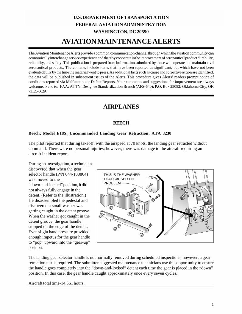
During an investigation, a techniciandiscovered that when the gearselector handle (P/N 644-183864)was moved to the“down-and-locked” position, it didnot always fully engage in thedetent. (Refer to the illustration.)He disassembled the pedestal anddiscovered a small washer wasgetting caught in the detent groove.When the washer got caught in thedetent groove, the gear handlestopped on the edge of the detent.Even slight hand pressure providedenough impetus for the gear handleto “pop” upward into the “gear-up”position.
The landing gear selector handle is not normally removed during scheduled inspections; however, a gearretraction test is required. The submitter suggested maintenance technicians use this opportunity to ensurethe handle goes completely into the “down-and-locked” detent each time the gear is placed in the “down”position. In this case, the gear handle caught approximately once every seven cycles.
Aircraft total time-14,561 hours.
THIS IS THE WASHERTHAT CAUSED THEPROBLEM
2
FAA AC 43-16A July 2001
Beech; Model C-23; Sundowner; Deteriorated Flexible Plumbing; ATA None
In the process of an annual inspection, a technician discovered that most of the flexible fluid lines installedin the aircraft were stiff and deteriorated.
Two of the flexible brake lines were chafing on the firewall and worn smooth. Also, the lines wereleaking through the hose sidewall in the chafed area. The technician replaced all the flexible brake linesbetween the tanks and the fuel selector valve.
All the flexible lines installed in this aircraft appeared to be original equipment and were approximately 30years old. This is considerably over the manufacturer’s recommended replacement time! A word to thewise should be sufficient; however, this type of report continues to be received.
Part total time in service-30+ years.
Beech; Model B24R; Sierra; Wing Flap Cable Damage; ATA 2750
While conducting an annual inspection, the technician discovered a wing flap cable was frayed.
The flap cable (P/N 169-524074) had several broken cable strands at one location. After furtherinvestigation, the technician found the cable contacted a screw head when the flaps were in the “full-up”position.
Although the submitter did not give the location of the screw head, he recommended installing chafeprotection on the screw head to protect the cable. He also suggested checking the flap cables forcondition during maintenance and inspections in the area.
Part total time not reported.
Beech; Model 35C33; Debonair; Empennage Cracks; ATA 5500
During a 100-hour inspection, the technician found several cracks in the empennage structure.
The cracks were located in the doubler (P/N 002-440000-143), the right skin section(P/N 33-410000-662), and the aft bulkhead (P/N 002-440024-65). There were two cracks in the doublerwith the same origin. It appeared the cracks began in a radius. One crack traveled outboard on the rightside approximately .75 inch, and the other crack traveled .5 inch to the left. The skin section crack wasapproximately 1.75 inches long, traveled from the aft skin edge, and terminated just above the .75 inchcrack in the doubler. The bulkhead crack, located at Fuselage Station (FS) 272, extended .375 inch downthe radii area at the top left corner.
The submitter did not offer a cause for this damage; however, he reported the aircraft was used in atraining environment.
Part total time-7,584 hours.
3
July 2001 FAA AC 43-16A
Beech; Model C90A; King Air; Defective Engine Heat Duct; ATA 3020
During a scheduled inspection, the technician discovered the right engine flexible heat duct on the leftexhaust stack was broken.
The heat duct (P/N 90-910100-17), that supplies hot air to the inlet lip for deicing, was broken at thelower end adjacent to the junction of the flexible and the end fitting of the duct.
This condition creates a very serious fire hazard and could endanger the aircraft flight safety. All thoseconcerned should inspect the engine hot air ducting for condition and security at every opportunity.
Part total time-992 hours.
Beech; Model C90B; King Air; Defective Vacuum System Distribution; ATA 3710
After returning from a flight, the pilot reported a loss of vacuum.
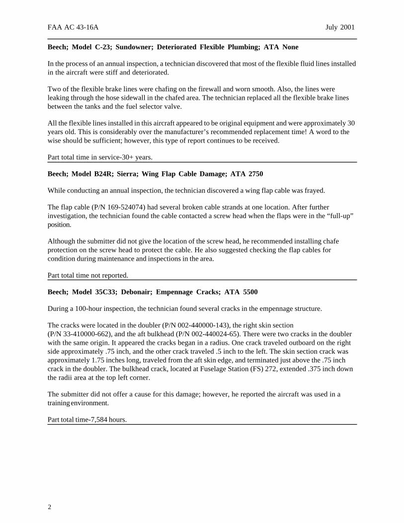
A technician investigated theproblem and found an aluminum line(P/N 101-320266-1) was chafingagainst the radar unit installed in theinstrument panel. The chafing actionhad penetrated the line wallthickness causing it to leak. Hespeculated this problem might beresponsible for pressurizationproblems. (Refer to the illustration.)
The submitter did not find supportclamps at the center of the line. Hesuspects vibration caused the line towear against the radar unit. Hesuggested inspecting like aircraft forproper clearance and support for theline.
Part total time-2,550 hours. DAMAGE LOCATION IS ONOPPOSITE SIDE OF TUBE
4
FAA AC 43-16A July 2001
Beech; Model F90; King Air; Aileron Skin Crack; ATA 5751
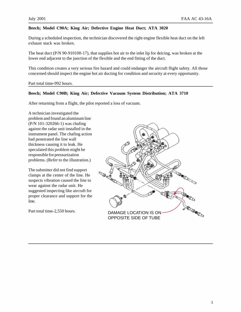
During a scheduled inspection, the technician discovered a 6-inch crack in the right aileron skin.
The top aileron (P/N 99-130000-617) was veryclose to complete failure and separation from theaircraft. (Refer to the illustration.)
The aircraft manufacturer issued Service Bulletin(SB) 57-3148, dated January 2001. The SB dealswith this subject and makes a repair kit(P/N 109-4011-1) available. The kit includes animproved replacement skin which is designed toprevent this type of failure.
The technician obtained and installed thereplacement skin kit. He suggested that the FAAconsider using this report as the subject of anAirworthiness Directive.
Part total time-5,981 hours.
Beech; Model A100; King Air; Severe Bleed Air Tubing Corrosion Damage; ATA 3610
During a scheduled inspection, the technician found an instrument bleed air tube was severely corroded.
The tube (P/N 50-970101-15), located in the center section of the left wing, displayed corrosion productsand the metal was “blistering.” Using the “ice-pick” test method, the technician could easily puncture thetube. The damaged area is located between 8 and 9 inches inboard of the coupling hose end of the tube.
The submitter suggested giving this area close attention during inspections and maintenance.
Part total time-8,904 hours.
Beech; Model B100; King Air; Uncommanded Engine Shutdown; ATA 7322
While taxiing for takeoff, the fightcrew experienced an uncommanded right engine shutdown. The crewsecured the right engine and taxied back to the parking ramp.
The technician discovered a line (P3) (P/N 896547-1) was disconnected from the fuel control. Sincethere was no apparent damage to the line, he reinstalled it and tightened it to the proper torque. The“B-nut,” used to attach the P3 line to the fuel control, has no provision for safety or security.
The submitter speculated the line was not properly torqued when it was installed during a recent engineassembly.
Part total time-103 hours since engine assembly.
CRACK

5
July 2001 FAA AC 43-16A
Beech; Model 1900; Airliner; Center Wing Spar Corrosion; ATA 5341
During a scheduled inspection, the technician found corrosion on the forward side of the main wing centersection spar cap. The corrosion was located in the “bond assembly” area of the lower spar cap.
The damaged area is located under the cabin floor. The corrosion was found on the forward face of thespar cap (P/N 118-100029-9) and was distributed across the area.
The submitter operates a fleet of seven like aircraft and has inspected them for similar corrosion. Allseven aircraft displayed varying amounts and stages of corrosion at the same location. The corrosiondamage on one aircraft required him to replace the spar cap.
The submitter recommended the manufacturer issue corrosion preventive measures to inhibit corrosion inthis area. He also suggested that adequate water drains be installed just forward of the spar cap toeliminate moisture buildup in this area. At this time, no drains are authorized or installed. He suggestedthat all operators of like aircraft conduct an inspection of this area for corrosion as soon as possible andreport the findings via FAA Form 8010-4, Malfunction or Defect Report.
Part total time not reported.
CESSNA
Cessna; Model 172R; Skyhawk; Defective Cowling Mounts; ATA 7110
This report was received from an FAA Certified Repair Station which operates a fleet of 16 like aircraft.
During inspections, technicians often find one or more defective cowling shock mounts (P/N J7444-36).Since February 2000, this operator has replaced 85 cowling mounts. The defects that are usually foundare rubber tearing or separating from the mounting plate and deterioration. With the new Model 172aircraft, the cowling mounts were changed to a “thinner” design.
The submitter suggested that the manufacturer consider returning to the use of the heavier cowling mountdesign.
Part total time-350 hours.
Cessna; Model 172RG; Cutlass; Landing Gear Failure; ATA 3230
During a check ride, the right main landing gear failed to extend. The pilot reached out the entry door andphysically pulled the gear into the locked position. After a safe landing, he summoned maintenancepersonnel.
While investigating, the technician discovered the splined section of the landing gear pivot(P/N 2441100-10) was twisted and separated from the remainder of the pivot.
6
FAA AC 43-16A July 2001
Cessna Service Bulletin (SB) 90-1 and Airworthiness Directive (AD) 2001-06-06 deal with the landinggear pivot problem. Service Bulletin 90-1 was complied with approximately 3-years prior, and the leftmain gear pivot was replaced at that time. Cessna SB 90-1 offers an improved pivot assembly to replaceones found defective. Airworthiness Directive 2001-06-06 was not issued until after this incidentoccurred.
The submitter believes AD 2001-06-06 should be amended to include repetitive pivot assemblyinspections instead of the one-time inspection now required.
Part total time-2,800 hours.
Cessna; Model 182; Skylane; Insufficient Elevator Travel; ATA 2730
While conducting a scheduled inspection, the inspector discovered the elevator up travel was insufficient.
The elevator traveled 19 degrees up; however, and the FAA Type Certificate Data Sheet requires 25degrees up travel. The technician discovered a directional gyro unit was mounted directly above thecontrol column. As the control column was pulled aft, a bolt (P/N AN3-10A) contacted the directionalgyro and stopped the elevator travel.
The maintenance records indicate the directional gyro unit was installed in 1993. The aircraft ownerstated, “The aircraft was always hard to make a good landing.” The submitter asked the followingquestion, “Had no mechanic checked the control travel since then?”
Part total time not reported.
Cessna; Model 182Q; Skylane; Wing Flap Damage; ATA 5750
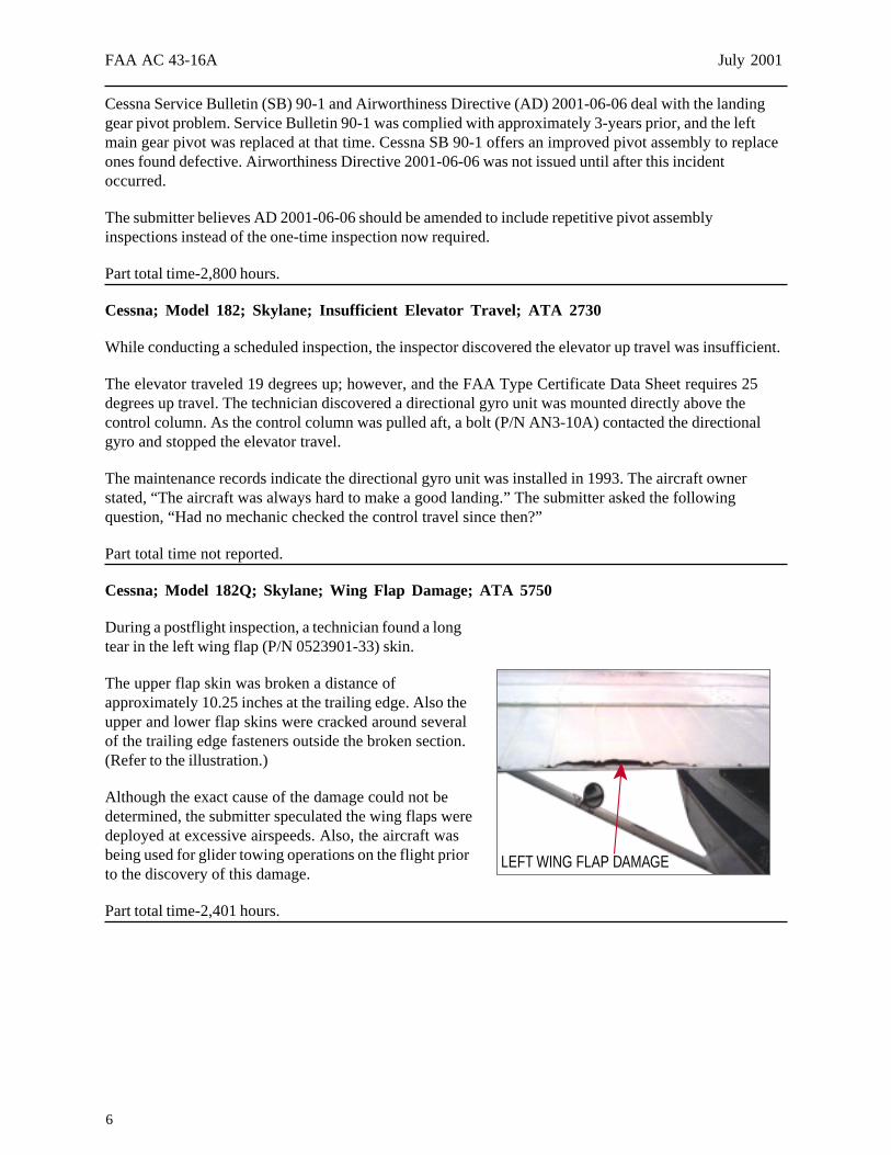
During a postflight inspection, a technician found a longtear in the left wing flap (P/N 0523901-33) skin.
The upper flap skin was broken a distance ofapproximately 10.25 inches at the trailing edge. Also theupper and lower flap skins were cracked around severalof the trailing edge fasteners outside the broken section.(Refer to the illustration.)
Although the exact cause of the damage could not bedetermined, the submitter speculated the wing flaps weredeployed at excessive airspeeds. Also, the aircraft wasbeing used for glider towing operations on the flight priorto the discovery of this damage.
Part total time-2,401 hours.
LEFT WING FLAP DAMAGE
7
July 2001 FAA AC 43-16A
Cessna; Model 195; Defective Aileron Hinge Brackets; ATA 2710
During an annual inspection, the technician discovered severe corrosion on the aileron hinge brackets.
The hinge brackets (P/N 0322709-1) are constructed of magnesium. The technician stated it is commonto find severe corrosion and cracking at the mounting feet and the main bearing boss. He suggestedconducting a “dye-penetrant” inspection on these parts during each annual inspection. Even if the hingebrackets appear serviceable, they should be stripped of paint and given a rigorous inspection.
There are numerous 190 and 195 models still in service after many years in service, and these olderaircraft deserve and require our close attention during inspections and maintenance.
Part total time-3,800 hours.
Cessna; Model T206H; Turbo Stationair; Oil Hose Damage; ATA 8120
During the first scheduled inspection since this aircraft was new, a technician found the turbocharger oilhose damaged.
The hose assembly (P/N LW12798-4S274) had been routed next to an engine exhaust system componentand was severely burned and leaking. He stated that failure of the oil hose would cause loss of engine oiland possibly engine failure.
Technicians and inspectors should be aware of the possibility of finding this defect on other like aircraft.
Part total time-110 hours.
Cessna; Model 206H; Stationair; Defective Rudder Trim Rigging; ATA 2721
The pilot returned from a flight and reported the aircraft required excessive left rudder pedal input tomaintain straight flight.
The technician found the rudder trim chain, tension adjustment idler sprocket (P/N 1260642-1) slipped inthe adjustment slot. The trim chain jumped out of position on the steering bungee gear causing limited leftrudder trim.
This condition could lead to a serious safety of flight hazard. The submitter recommended thatmaintenance personnel use due diligence when inspecting and maintaining this, as well as other, flightcontrol systems.
Part total time-424 hours.
8
FAA AC 43-16A July 2001
Cessna; Model 340A; Wheel Brake Leak; ATA 3242
The aircraft returned from a flight, and a technician found hydraulic fluid on the fuselage lower skin.
Investigating further, he discovered the aluminum line (P/N 5300116) carrying fluid to the right wheelbrake was leaking. The line was chafing against a heat duct and was leaking at a pinhole in the chafedarea. He stated it appeared the leak was accelerated by corrosion at the chafed area. This defect couldcause loss of braking action on the right side and create a safety hazard.
The submitter installed a new brake line, routed it to provide adequate clearance, and installed antichafingprotection. He suggested giving this area close scrutiny during scheduled inspections.
Part total time-3,792 hours.
Cessna; Model 414A; Chancellor; Aileron Anomaly; ATA 2710
While conducting an inspection, the technician noticed the right aileron was not streamlined with thetrailing edge of the wing.
The outboard end of the aileron was approximately .25 inch high when the inboard end was even with thetrailing edge of the wing. After further inspection, the technician discovered the outboard aileron hingebracket (P/N 5021002-13) was an incorrect part for this installation. The hinge bracket part numberindicated was intended for installation on the left aileron.
The aircraft maintenance records revealed the incorrect hinge bracket was installed during a previouswing repair. The submitter stated the manufacturer’s parts catalog has an error, which led to installationof the incorrect part.
Part total time not reported.
Cessna; Model 560; Citation; Flight Control Interference; ATA 2700
The pilot reported that after takeoff, he climbed to 38,000 feet. Approximately 10 minutes later, henoticed the autopilot disengaged, and the flight controls felt jammed. After applying considerable pressureto the control column, the flight controls broke free and operated properly.
When the aircraft was parked on the ramp, maintenance personnel investigated this occurrence. As atechnician removed an access panel (321 ABC) approximately 1 gallon of water poured out. Prior to theflight, the aircraft was parked outside during a heavy rainstorm. The rainwater accumulated inside thepanel, froze at altitude, and the ice constricted the flight control cables.
The rib at fuselage station (FS) 449 does not have a drain hole at the bottom to allow accumulated waterto flow forward to the fuselage drain ports. Cessna engineering authorized the technician to drill a drainhole at the bottom of the rib to eliminate accumulated water through the fuselage drain ports.
Aircraft total time-235 hours.
9
July 2001 FAA AC 43-16A
DIAMOND
Diamond; Model DA-20-A1; Nose Landing Gear Cracks; ATA 3222
During a preflight inspection, the pilot found the nose landing gear fork cracked.
Both sides of the nosewheel fork (P/N 20-3220-00-16) were cracked through approximately 75 percentof their width. The cracks were obscured by paint and the wheel pant installation.
The nosewheel fork assembly was in imminent danger of complete failure and separation from theaircraft. The submitter speculated a hard landing or a “nosewheel-first landing” caused the wheel forkcracks.
Aircraft total time-1,195 hours.
DASAULT
Dasault; Model AMD-10; Falcon; Hydraulic System Failure; ATA 2913
While starting the right engine, the flightcrew heard an unusual noise, that lasted approximately 30seconds. They noticed the “HYD 2” light was illuminated and the pressure indicator was at “zero.” Thecrew shutdown the aircraft and summoned maintenance personnel.
The technician removed the right engine-driven hydraulic pump (P/N ABEX 40053-03) and discoveredthe drive shaft was intact; however, it rotated with little or no resistance. It was evident to the technicianthat the pump had failed internally. He did not disassemble the pump to determine the cause of theinternal failure.
The “time-before-overhaul (TBO)” for the hydraulic pump is 3,000 hours of operation. The submitterstated this pump “rarely” reaches TBO.
Part total time-789 hours.
ERCOUPE
Ercoupe; Model 415C; Altimeter Failure; ATA 3416
During the first flight after the installation of a newly overhauled altimeter, the instrument failed. The pilotnoticed the “100-foot” indicator needle had stopped working.
A technician removed the (Kollsman) altimeter and noticed the shaft for the “100-foot” needle haddisengaged internally. By tilting the altimeter in one direction, he could cause the shaft to re-engage withthe internal mechanism. Tilting the altimeter in the opposite direction (simulating an aircraft climb attitude)caused the needle to disengage again.
An FAA certified repair station overhauled the altimeter. The instrument was returned to the overhaulshop, and at the time of this report, the cause of this defect had not been determined.
Part total time since overhaul-1 hour.
10
FAA AC 43-16A July 2001
GRUMMAN AMERICAN
Grumman American; Model AA-5A; Cheetah; Wing Structural Damage; ATA 5712
While performing other maintenance on the left wing fuel tank, the technician found a buckled wing rib atthe aft end of the rib at wing station (WS) 66.
The aircraft owner related that the aircraft had suffered previous structural damage when an insect nestplugged the left wing fuel tank vent. After the flight, the pilot noticed the skin covering the left fuel tankarea was distorted. The insect nest was cleaned out. However, it was evident there was no effort toevaluate the aircraft damage. This aircraft has been operating approximately 7 years since the previousdamage occurred.
The submitter reminds us that after repairing “obvious” damage, it is important to thoroughly inspect thearea for “hidden” damage.
Part total time-4,247 hours.
PIPER
Piper; Model PA 23-160; Apache; Cabin Entry Door Defect; ATA 5210
The pilot reported the cabin entry door came open in flight causing him to lose directional control of theaircraft. He regained directional control and landed the aircraft safely.
During an investigation, a technician discovered the cabin door latch assembly would not lock the doorsecurely. The latch did not properly engage with the doorjamb and allowed the door to “pop” open duringthe flight. Giving the door latch assembly proper adjustment and lubrication should prevent recurrence ofthis defect.
Part total time not reported.
Piper; Model PA 23-160; Apache; Wing Structural Defect; ATA 7120
While performing other maintenance on the right engine, a technician discovered the engine mount trusswas broken.
The engine mount truss (P/N 17137-01) consists of steel tube construction. It seemed obvious to thetechnician that the failure was caused by severe corrosion. The corrosion was concentrated inside of thesteel tube of the truss.
Because of the severity of the corrosion damage, the submitter recommended replacing the entire landinggear/engine truss assembly. He recommended giving this area close attention during scheduledinspections and maintenance.
Part total time not reported.
11
July 2001 FAA AC 43-16A
Piper; Model PA 24; Commanche; Engine Exhaust Stack Broken; ATA 7810
During a flight, the pilot experienced a complete loss of engine power and was unable to regain power.He made a safe and successful off-airport landing.
The technician discovered the right rear engine exhaust stack (P/N 21092-17) was broken inside thecarburetor heat muff. When the broken exhaust stack dropped down and chafed a hole in the heat muff,hot engine exhaust gasses entered the engine compartment. As a result, the insulation melted on the“P-lead” wires, that shorted to ground, causing the engine to fail.
The submitter suggested that when the carburetor heat muff is opened during annual inspections, a smallmirror should be used to check the area where the exhaust stack is welded to the heat muff.
Aircraft total time-4,053 hours.
Piper; Model PA 28-181; Archer; Defective Alternator Fitting; ATA 2421
While conducting other maintenance in the engine compartment, the technician noticed a brokenalternator attachment.
The alternator (P/N ES4032) end plate (P/N ALE1003K) attachment “ear” was broken and separated.The submitter stated, “This is the fifth one in our fleet found with this defect.”
The submitter speculated the alternator drivebelt tension might have been excessive and caused orcontributed to this failure. Also, the alternator mounting system for this installation may have been acontributing factor.
Part total time-1,710 hours.
Piper; Model PA 31-350; Chieftain; Alternator Failure; ATA 2421
The pilot reported that during a flight, he noticed the left engine alternator warning light illuminated. Heattempted to reset the circuit breaker without success. After a safe landing, he summoned maintenancepersonnel.
While investigating the problem, a technician discovered the positive battery lug was loose. The loose lugallowed the terminal to short to the case ground causing the battery cable insulation to melt, opening thealternator circuit breaker. He replaced the alternator (Electrosystems P/N ALU-8521) and battery cable.
The submitter did not offer a cause for the loose battery cable; but it is currently being investigated.
Part total time-54 hours.
Piper; Model PA 31-350; Chieftain; Defective Cabin Heater; ATA 2140
The aircraft was at the “HOLD SHORT” point on the end of the runway when the control tower notifiedthe pilot of a cloud of smoke coming from the right side of the aircraft.
A technician discovered the smoke was coming from the combustion heater (ElectrosystemsP/N B4500). He determined the heater had exceeded the high temperature limit and “belched” smokeback through the blower motor inlet. He conducted a decay test on the heater and found it was within
12
FAA AC 43-16A July 2001
serviceable limits; however, the heater still did not function properly. At this point, he removed andreplaced the fuel nozzle and solved the problem. The old fuel nozzle allowed excessive fuel in thecombustion chamber, which caused an overtemperature condition and produced the smoke and fumes.
The submitter suggested inspecting the fuel nozzle frequently and, when needed, replacing it to preventfurther recurrence of this defect.
Part total time-1,031 hours.
Piper; Model PA 31T-500; Cheyenne; Electrical Short Circuit; ATA 2400
Just after takeoff, the pilot smelled and saw smoke coming from the left main circuit breaker panel. Heimmediately returned to the departure airport and landed the aircraft safely.
The technician removed the circuit breaker panel (P/N 29371-2) and found severe heat damage. Thedamage was centered at the attachment clip for the “right windshield heat” circuit breaker. This aircraftuses the “plug in type” circuit breakers. He discovered the small brass rivet, used to attach the clip insidethe circuit breaker panel, was not making sufficient contact to carry the required 35 amp electrical load.
The submitter recommended that operators of like aircraft conduct an inspection for heat damage insidethe main circuit breaker panel.
Part total time-3,675 hours.
Piper; Model PA 31T-620; Cheyenne; Landing Gear Door Hinge Broken; ATA 5280
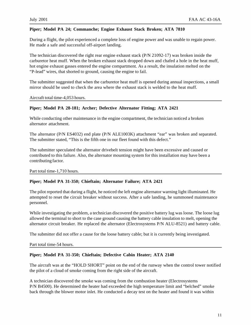
During a postflight inspection, a technician discovered a main landing gear hinge was broken.
The forward left main landing gear outboard doorhinge fitting (P/N 42059-07) had failed. (Refer to theillustration.) The technician removed the door andfound the rear hinge fitting was cracked in the samearea where the forward hinge failed. This finding ledthe technician to inspect the same door on the rightmain gear where he also found cracks.
The submitter stated he has found this type of defecton several like aircraft. He recommended givingspecial attention to the main gear door hinges duringinspections. He warned that even a slight paintseparation might indicate an underlying crack.
Part total time-5,190 hours.
Piper; Model PA 32-300; Cherokee Six; Electrical System Malfunction; ATA 2400
After returning from a flight, the pilot parked the aircraft and began the shutdown procedure.
When the pilot turned off the master switch, he heard a “pop” that seemed to come from the right side ofthe instrument panel. None of the circuit breakers were open, but he detected a burning smell and noticedsmoke coming from behind the panel just to the left of the circuit breakers. He exited the aircraft andsummoned maintenance personnel.
13
July 2001 FAA AC 43-16A
A technician investigated and discovered the rheostat assembly, wiring, and other components of thecabin light electrical circuit were severely burned. He did not explain what caused this defect.
Part total time-15,481 hours.
Piper; Model PA 46-350; Malibu; Landing Gear Actuator Defect; ATA 3230
During a landing approach, the right main landing gear did not indicate “down-and-locked” when the pilotselected the down position. After conducting aerial maneuvers designed to assure the gear was lockeddown, a “down-and-locked” indication was attained, and the pilot landed the aircraft safely.
After an inspection, a technician checked the right main gear actuator (Parker-Hannafin P/N 89075-005)and adjusted the “down-and-locked” switch in accordance with the proper technical data. Afterconducting an operational test, the landing gear functioned correctly, and he approved the aircraft forreturn to service.
On the next flight, the same scenario occurred and terminated with another safe landing.
The submitter believes there is a problem with the servicing information contained in the technical datawhich contributes to this type of failure. He states, “These actuators have a problem that (proper) routineservicing can prevent.”
Part total time-1,270 hours.
HELICOPTERS
BELL
Bell; Model 206B; Jet Ranger; Defective Transmission; ATA 6330
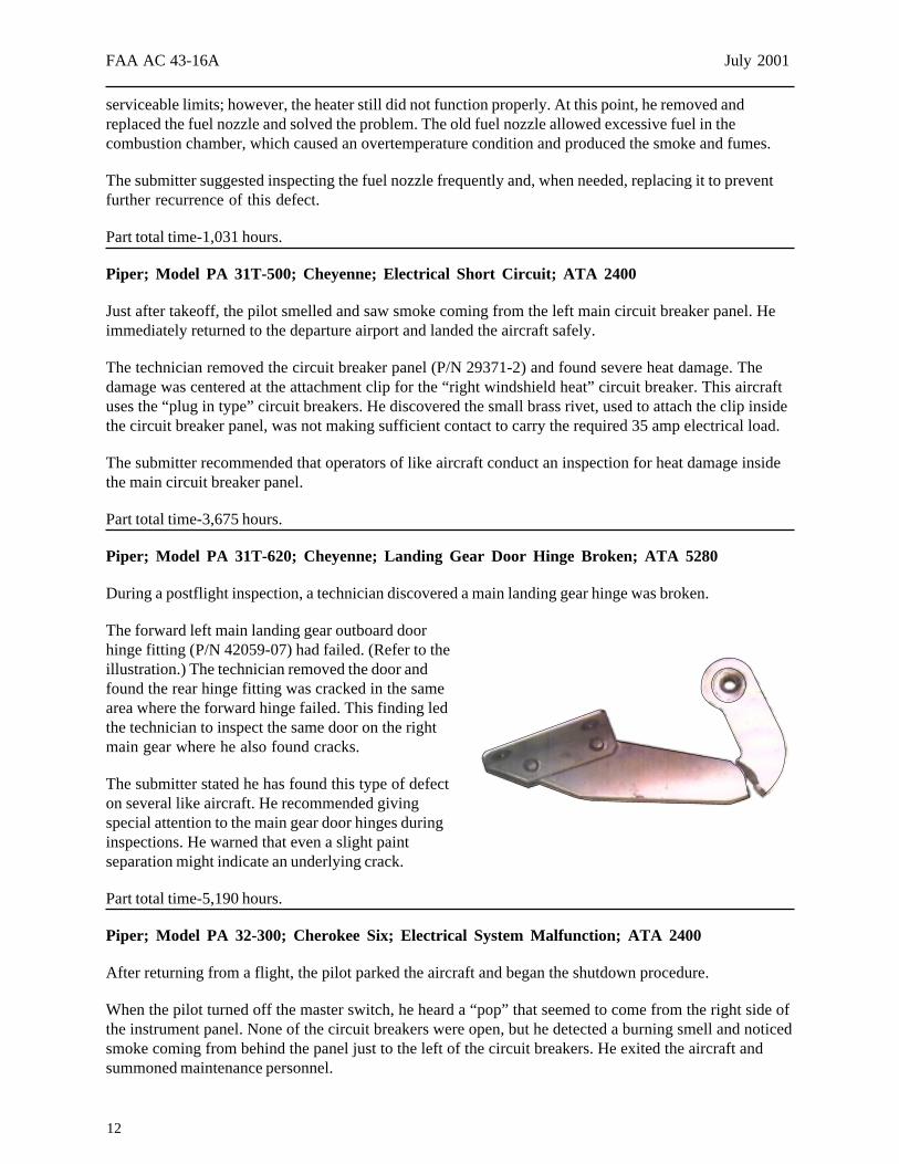
During a scheduled inspection and maintenance, a technician discovered the transmission case wascracked.
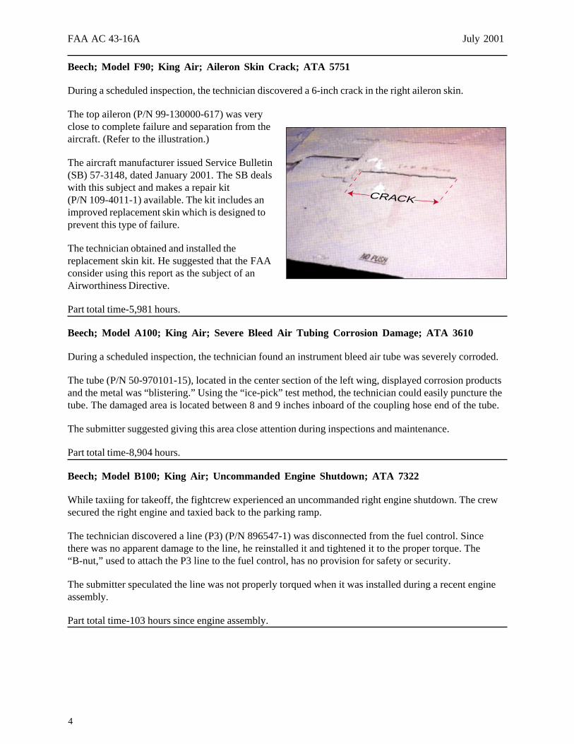
The lower transmission case (P/N 206-040-150-029) was cracked at fourlocations adjacent to the support webs. (Refer to the illustration.)
The submitter did not give a cause for this defect or any further details.It is possible the case cracks were caused by metal fatigue resulting from ahigh number of operating hours.
Part total time-7,457 hours.
CRACKS AT 4 LOCATIONS
14
FAA AC 43-16A July 2001
Bell; Model UH-1H; Huey; Main Rotor Blade Defect; ATA 6210
This helicopter is operated by the U.S. Forestry Service as a “Public Use Aircraft.”
During a postflight inspection, a technician discovered a small dent in the main rotor blade.
The dent was aft of the spar on the top of the blade. The technician found a crack inside the dent. Heremoved the paint and discovered the crack traveled approximately 6 inches.
The submitter gave no cause for this defect.
Part total time-1,649 hours.
EUROCOPTER
Eurocopter; Model BK-117B1; High Frequency Vibration; ATA 6310
While preparing for a flight, the pilot brought the number one engine up to ground idle and started thenumber two engine. When the pilot brought the number two engine to ground idle, he felt a “thud” and asevere high frequency vibration. He immediately shut down both engines.
The pilot and a technician inspected the engine compartments and found that the drive shaft, that goesfrom the number two engine to the transmission (P/N 117-12005.01H6), was bent and twisted.
The technician contacted and explained the problem to the manufacturer’s technical supportrepresentative. The manufacturer’s representative offered his opinion that the clutch (P/N 4639 202 011)did not engage until the number two engine was at ground idle causing twisting and bending of the driveshaft when it was finally engaged.
Part total time since overhaul-80 hours.
McDONNELL DOUGLAS
McDonnell Douglas; Model 369D; Oil Cooler Blower Failure; ATA 7921
During shutdown procedures, the pilot heard a loud grinding and popping sound that seemed to come fromthe transmission area.
A technician removed and disassembled the oil cooler blower assembly (P/N 369D25630-101) anddiscovered the lower blower bearing (P/N 369A5655-3) had failed. He suspected the bearing cage failedfirst followed by the remainder of the bearing.
The manufacturer established a 1,200 hour life limit for the blower bearing. In this case, the bearing failedat less than half the life limit time expended.
Part total time-515 hours.
15
July 2001 FAA AC 43-16A
ROBINSON
Robinson; Model R-22; Mariner; Tail Boom Separation; ATA 6510
The Civil Aviation Safety Authority (CASA) of Australia submitted the information for this article. Thearticle is published as it was received.
During a run-up prior to takeoff, the tail rotor drive shaft broke and severed the tail boom.
A preliminary inspection indicated the incident was initiated by failure of the tail rotor drive shaftdamper. This allowed the drive shaft to whip, fracture, and cut off the tail boom and cause collateraldamage to the helicopter. This is not the only incident involving tail rotor drive shaft damper clipfailure. The manufacturer issued Service Bulletin (SB) 14, dated October 1981, which changed thematerial in the arm from aluminum to steel. In addition, Robinson issued SB 20, dated May 1982,which calls for a run-up inspection and friction test of the damper each 100-hours of operation.
CASA inquired of the FAA their intentions to issue an Airworthiness Directive concerning thisanomaly and require compliance with SB 20.
Helicopter total time not reported.
Robinson; Model R-44; Astro; Poor Engine Performance; ATA 7414
While preparing for a flight, the pilot started the engine and performed a check of the magnetos. When heselected the “left” magneto position, the engine quit. He restarted the engine with the magneto switch inthe “both” position, and the engine began backfiring and running very poorly.
The pilot told the technician that this helicopter “had a history of difficult starting.” The technicianchecked the magneto (TCM P/N 10-600616-200) timing and noticed the left magneto would only turnintermittently with the engine. After further investigation, he discovered the “Woodruff” key slot in thepinion gear (P/N 10-157120Y) was severely worn. Over half of the material between the gear insidediameter and the gear teeth grooves was worn away, and the magneto case was filled with debris.
The magneto had been tested and repaired by a certified maintenance shop 224 hours prior to thisoccurrence.
Part total time since overhaul-1,396 hours.
AMATEUR, EXPERIMENTAL, AND SPORT AIRCRAFT
LONG EASY
Long Easy; Model CB540; Canopy Failure; ATA 5210
During a flight, the canopy separated from the aircraft which resulted in an incident with minor damage tothe aircraft but no personal injuries.
16
FAA AC 43-16A July 2001
The inspector examined the frame and the remains of the canopy and determined the latch assembly hadfailed.
The submitter gave no further details concerning this incident.
Aircraft total time not reported.
HOT AIR BALLOONS
THUNDER & COLT
Thunder & Colt; Burner Model C-3T; Magnum; Defective Fuel Distribution Block; ATA 5102
This balloon uses a Balloon Works envelope and a Thunder & Colt gondola and burner.
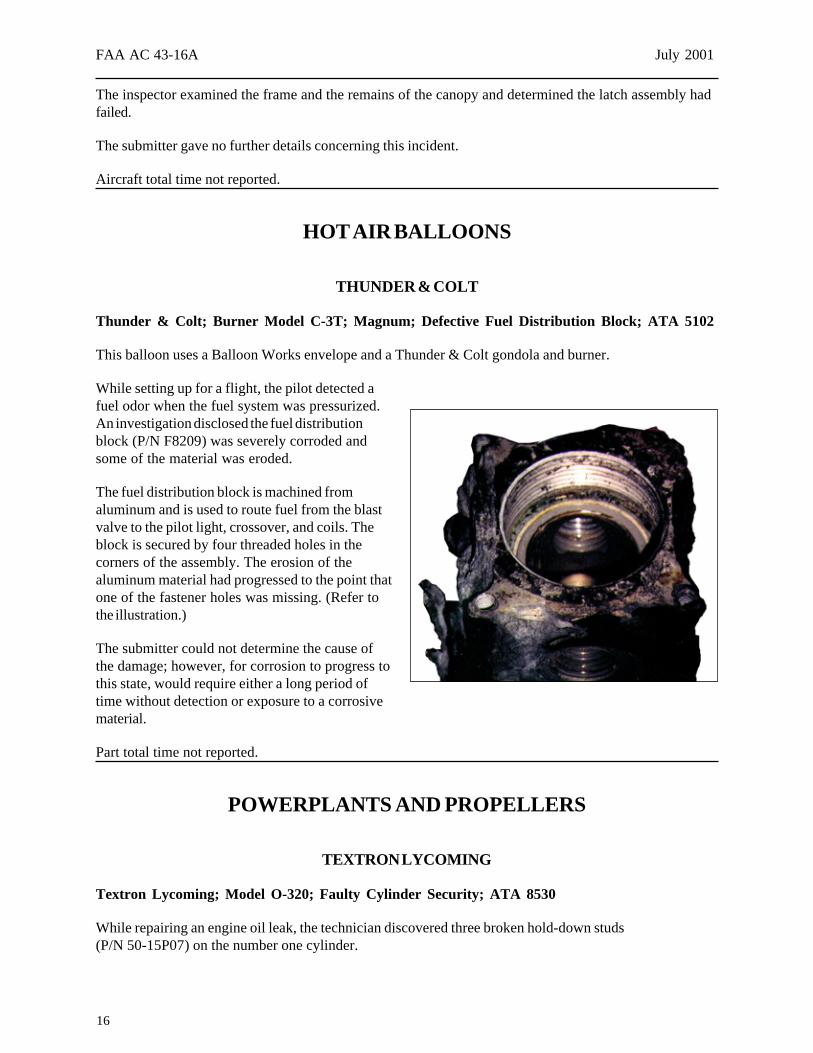
While setting up for a flight, the pilot detected afuel odor when the fuel system was pressurized.An investigation disclosed the fuel distributionblock (P/N F8209) was severely corroded andsome of the material was eroded.
The fuel distribution block is machined fromaluminum and is used to route fuel from the blastvalve to the pilot light, crossover, and coils. Theblock is secured by four threaded holes in thecorners of the assembly. The erosion of thealuminum material had progressed to the point thatone of the fastener holes was missing. (Refer tothe illustration.)
The submitter could not determine the cause ofthe damage; however, for corrosion to progress tothis state, would require either a long period oftime without detection or exposure to a corrosivematerial.
Part total time not reported.
POWERPLANTS AND PROPELLERS
TEXTRON LYCOMING
Textron Lycoming; Model O-320; Faulty Cylinder Security; ATA 8530
While repairing an engine oil leak, the technician discovered three broken hold-down studs(P/N 50-15P07) on the number one cylinder.
17
July 2001 FAA AC 43-16A
After further investigation, the technician found that all but two on the remaining hold-down stud nuts hadbacked off the threads. He believes the entire cylinder was in imminent danger of separating from theengine case. He checked the hold-down stud nuts on both engines and discovered they were below therequired torque value.
The submitter suggested conducting at least a random check of the hold-down stud nuts for proper torqueat every opportunity.
Part total time not reported.
ACCESSORIES
AIRCRAFT TIRE ANOMALY
Piper; Model PA 12; Super Cruiser; Main Landing Gear Tire Anomaly; ATA 3244
The aircraft owner asked a technician to replace the main landing gear tires.
The technician mounted two new tires (Goodyear P/N 856C61-3), size 8.50 by 6 on identical Clevelandwheels. When he noticed something “just didn’t look right,” he investigated further. After he inflated eachtire to 25 PSI, he noticed one tire appeared larger than the other tire. He measured the diameter of bothtires and found a difference of .8125 inch. One of the tires had a diameter of 20.125 inches, and the othertire diameter was 20.9375 inches.
After a bit of research, the technician discovered the tire specifications furnished to the FAA byGoodyear, in accordance with Technical Standard Order (TSO) C62D, indicate the diameter limits for thistire are 21.15 inches minimum and 22.85 inches maximum. Therefore, the smaller diameter tire wasbelow the minimum diameter limit.
It seems odd to the submitter that the diameter tolerance is so great. Accordingly, one tire couldbe 1.7 inches smaller in diameter than the other and still be within the tolerance limits.
Part total time not applicable.
AIR NOTES
INSTALLATION OF RETROFIT SHOULDER HARNESSES
This has been the subject of many debates among aviation folks (including FAA personnel) for manyyears. Can I do the installation legally? Is it a major or minor alteration? Can I get a field approval?Is there a Supplemental Type Certificate (STC)?
Well, the FAA has clarified at least some of the points of conjecture by issuing Policy Statement (PS)number ACE-00-23.561-01, dated September 19, 2000. This 17-page document goes a long way inclearing up some of the misunderstandings, which have circulated through the industry for many years,mutating as they were passed from one person to another.
18
FAA AC 43-16A July 2001
The following is an excerpt from PS ACE-00-23.561-01 and is intended for information only. Concernedindividuals should obtain the full text of this document before any shoulder harness installation. Thisarticle is published as it was received.
SUMMARYA retrofit shoulder harness installation in a small airplane may receive approval by Supplemental TypeCertificate (STC), Field Approval, or as a minor change. An STC is the most rigorous means ofapproval and offers the highest assurance the installation meets all the airworthiness regulations.A Field Approval is a suitable method of approval for a shoulder harness installation that needs littleor no engineering. Shoulder harness installations may receive approval as a minor change in certaincases. In such cases, the FAA certified mechanic who installs the shoulder harness records it as aminor change by making an entry in the maintenance log of the airplane.
The FAA does not encourage the approval of retrofit shoulder harness installations as minor changes.The preferred methods of approval are STC or Field Approval. However, the FAA should not forbidthe approval of a retrofit shoulder harness installation as a minor change in:
The front seats of those small airplanes manufactured before July 19, 1978, and
In other seats of those small airplanes manufactured before December 13, 1986.
A retrofit shoulder harness installation may receive approval as a minor change in these smallairplanes if:
The installation requires no change of the structure (such as welding or drilling holes).
The certification basis of the airplane is 14 CFR part 23 before Amendment 23-20, part 3 of theCivil Air Regulations, or a predecessor regulation.
In addition, a minor change installation should follow the guidance for hardware, restraint angles, andattachment locations provided in:
Advisory Circular (AC) 43.13-2A, Acceptable Methods, Techniques, and Practices AircraftAlterations.
AC 21-31, Shoulder Harness – Safety Installations.
AC 23-4, Static Strength Substantiation of Attachment Points for Occupant Restraint SystemInstallations.
Installations approved as a minor change may not provide the occupant with the protection requiredby regulation (Civil Air Regulation (CAR) 3.386 or 14CFR part 23, § 23.0561). However, a properlyinstalled retrofit shoulder harness installation is a safety improvement over occupant restraint by seatbelt alone.”
Basically, if the aircraft has the hard-points factory installed and the approved shoulder harnesssystem can be installed without modification of the airframe, it would be a minor change.
The full text of PS ACE-00-23.561-01 is available on the Internet. It is in the “Federal Register” forThursday, September 28, 2000. The document is listed under “Federal Aviation Administration,”“Notices.”
19
July 2001 FAA AC 43-16A
Printed copies of PS ACE-00-23.561-01 are available by written request to: FAA, Small AirplaneDirectorate (ACE-111), Room 301, 901 Locust, Kansas City, MO 64106.
ALL AIRWORTHINESS DIRECTIVES ARE ON THE WEB
The FAA, Aircraft Certification and Flight Standards Services are pleased to announce that allAirworthiness Directives (ADs) are now available on the Internet in the Regulatory and GuidanceLibrary (RGL).
The Internet address is: <http://www.airweb.faa.gov/rgl>
In addition, you can find the ADs from the FAA homepage by clicking on “FAA Organizations” and then“Aircraft Certification Service.”
This improvement should be of great benefit to aircraft owners, operators, technicians, pilots, and otherinterested persons.
SUBSCRIPTIONS
The Government Printing Office (GPO) distributes this publication. If you have any questions regardinga subscription to this publication, please direct your questions to GPO.
You may contact GPO at: Superintendent of Documents, P.O. Box 371954, Pittsburgh, PA 15250-7954,telephone (202) 512-2250, fax (202) 512-1800.
When you contact GPO, be specific concerning the publication you are interested in (e.g., AdvisoryCircular 43-16A). GPO accepts payment in the form of checks and credit cards. Please make yourchecks payable to the Superintendent of Documents.
In the past, we furnished the GPO subscription form in this publication. The older issues which containthe subscription form, may not have current pricing information. Since GPO controls price increases,contact GPO for current subscription information.
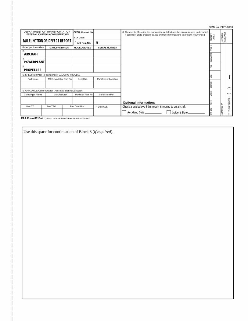
ELECTRONIC VERSION OF MALFUNCTION OR DEFECT REPORT
One of the recent improvements to the AFS-600 Internet web site is the inclusion of FAA Form 8010-4,Malfunction or Defect Report. This web site is still under construction and further changes will be made;however, the site is now active, usable, and contains a great deal of information.
Various electronic versions of this form have been used in the past; however, this new electronic versionis more user friendly and replaces all other versions. You can complete the form online and submit theinformation electronically. The form is used for all aircraft except certificated air carriers who are
20
FAA AC 43-16A July 2001
provided a different electronic form. The Internet address is: http://av-info.faa.gov/isdr/
When the page opens, select “M or D Submission Form” and, when complete, use the “Add ServiceDifficulty Report” button at the top left to send the form. Many of you have inquired about this service. Itis now available, and we encourage everyone to use this format when submitting aviation, service-relatedinformation.
SERVICE DIFFICULTY PROGRAM DATA ON THE INTERNET
The FAA, Service Difficulty Reporting (SDR) Program is managed by the Aviation Data SystemsBranch, AFS-620, located in Oklahoma City, Oklahoma. The information supplied to the FAA in the formof Malfunction or Defect Reports (M or D), Service Difficulty Reports (SDR), or by other means, isentered into the SDR data base. This information has been available to the public through individualwritten request. This method has provided the aviation public with an invaluable source of data forresearch or finding specific problems and trends.
The Service Difficulty Reporting Program relies on the support of the aviation public to maintain the highquality of data. AFS-620 has included the SDR data on an Internet web site, which is now available to thepublic. Using the web site will expedite the availability of information. The Internet web site addressis: http://av-info.faa.gov
On this web site, select “Aircraft” along the top of the page, next select “Service Difficulty Reporting,”and then select “Query SDR Data.”
This web site is now active; however, it is still under development and improvements are being made. Weask for your patience, ideas, and suggestions. If you find the web site useful, let us know. Also, spreadthe word about the availability of information on the web site. To offer comments or suggestions, you maycontact the web master or call Tom Marcotte at (405) 954-4391.
The data base now includes a more comprehensive search/query tool with provisions for printing reportsor downloading data.
Please remember that the information contained in the SDR data base is only as good as the input wereceive from the aviation public in the form of SDR and M or D reports. Also, the data used in productionof this publication is derived from the SDR data base. In that regard, we solicit and encourage yourparticipation and input of information.
This publication, as well as many other publications, was previously included on the “FedWorld” internetsite. The FedWorld site was terminated on April 15, 2000. The data previously listed there is presentlybeing transferred to the “av-info” web site.
21
July 2001 FAA AC 43-16A
ADDRESS CHANGES
In the past, the Designee Standardization Branch (AFS-640) maintained the mailing list for thispublication. Now, the Government Printing Office (GPO) sells this publication and maintains the mailinglist; therefore, please send your address change to: U.S. Government Printing Office, ATTN: SSOM,ALERT-2G, 710 N. Capital Street N. W., Washington, DC 20402
You may also send your address change to GPO via FAX at: (202) 512-2168. If you FAX your addresschange, please address it to the attention of: SSOM, ALERT-2G. Whether you mail or FAX youraddress change, please include a copy of your old address label, and write your new address clearly.
IF YOU WANT TO CONTACT US
We welcome your comments, suggestions, and questions. You may use any of the following means ofcommunication to submit reports concerning aviation-related occurrences.
Editor: Phil Lomax (405) 954-6487FAX: (405) 954-4570 or (405) 954-4748
Mailing address: FAA, ATTN: AFS-640 ALERTS, P.O. Box 25082,Oklahoma City, OK 73125-5029
E-Mail address: [email protected]
You can access current and back issues of this publication from the internet at: http://afs600.faa.gov
When the page opens, select “AFS-640” and then “Alerts” from the drop-down menu. The monthlyissues of the Alerts are available back to July 1996, with the most recent edition appearing first.
AVIATION SERVICE DIFFICULTY REPORTS
The following are abbreviated reports submitted between May 22, 2001 and June 15, 2001, which havebeen entered into the FAA Service Difficulty Reporting (SDR) System data base. This is not an allinclusive listing of Service Difficulty Reports. For more information, contact the FAA, Regulatory SupportDivision, Aviation Data Systems Branch, AFS-620, located in Oklahoma City, Oklahoma. The mailingaddress is:
FAAAviation Data Systems Branch, AFS-620PO Box 25082Oklahoma City, OK 73125
These reports contain raw data that has not been edited. If you require further detail please contactAFS-620 at the address above.
22
FAA AC 43-16A July 2001
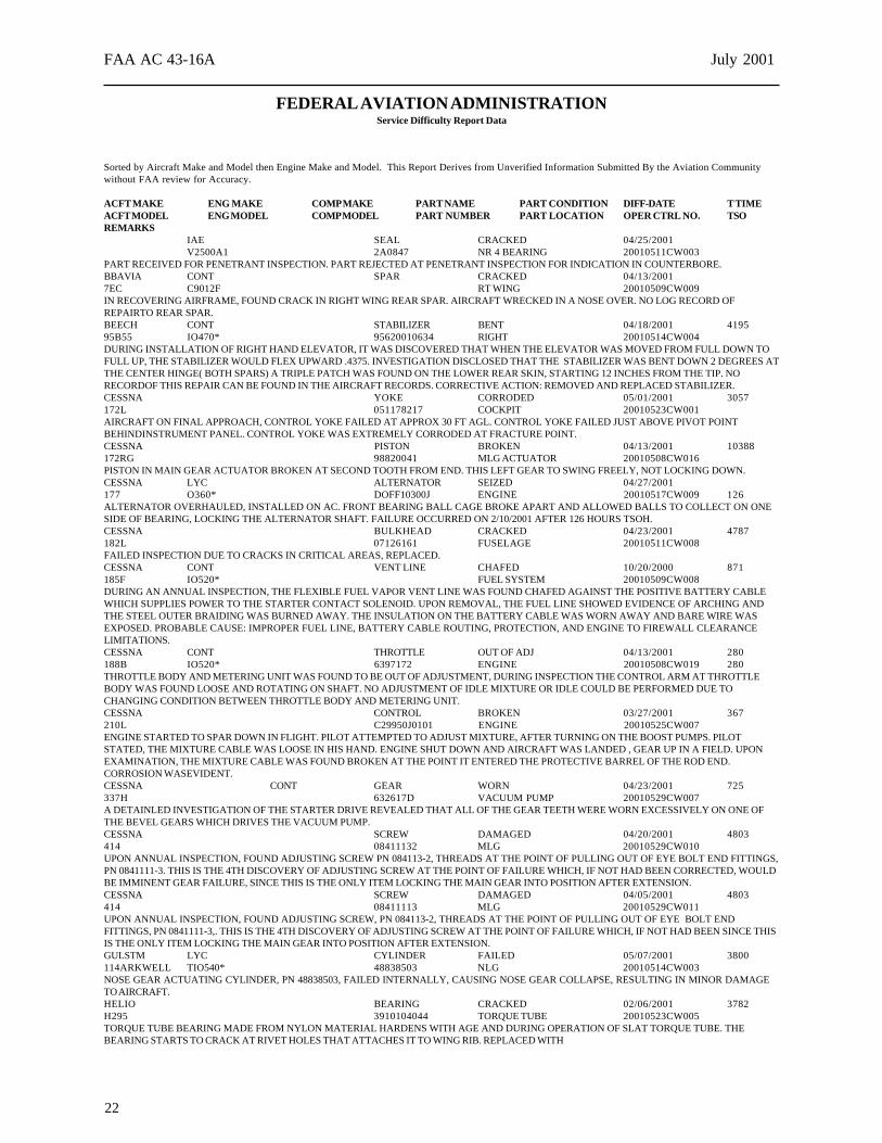
FEDERAL AVIATION ADMINISTRATIONService Difficulty Report Data
Sorted by Aircraft Make and Model then Engine Make and Model. This Report Derives from Unverified Information Submitted By the Aviation Communitywithout FAA review for Accuracy.
ACFT MAKE ENG MAKE COMP MAKE PART NAME PART CONDITION DIFF-DATE T TIMEACFT MODEL ENG MODEL COMP MODEL PART NUMBER PART LOCATION OPER CTRL NO. TSOREMARKS
IAE SEAL CRACKED 04/25/2001V2500A1 2A0847 NR 4 BEARING 20010511CW003
PART RECEIVED FOR PENETRANT INSPECTION. PART REJECTED AT PENETRANT INSPECTION FOR INDICATION IN COUNTERBORE.BBAVIA CONT SPAR CRACKED 04/13/20017EC C9012F RT WING 20010509CW009IN RECOVERING AIRFRAME, FOUND CRACK IN RIGHT WING REAR SPAR. AIRCRAFT WRECKED IN A NOSE OVER. NO LOG RECORD OFREPAIRTO REAR SPAR.BEECH CONT STABILIZER BENT 04/18/2001 419595B55 IO470* 95620010634 RIGHT 20010514CW004DURING INSTALLATION OF RIGHT HAND ELEVATOR, IT WAS DISCOVERED THAT WHEN THE ELEVATOR WAS MOVED FROM FULL DOWN TOFULL UP, THE STABILIZER WOULD FLEX UPWARD .4375. INVESTIGATION DISCLOSED THAT THE STABILIZER WAS BENT DOWN 2 DEGREES ATTHE CENTER HINGE( BOTH SPARS) A TRIPLE PATCH WAS FOUND ON THE LOWER REAR SKIN, STARTING 12 INCHES FROM THE TIP. NORECORDOF THIS REPAIR CAN BE FOUND IN THE AIRCRAFT RECORDS. CORRECTIVE ACTION: REMOVED AND REPLACED STABILIZER.CESSNA YOKE CORRODED 05/01/2001 3057172L 051178217 COCKPIT 20010523CW001AIRCRAFT ON FINAL APPROACH, CONTROL YOKE FAILED AT APPROX 30 FT AGL. CONTROL YOKE FAILED JUST ABOVE PIVOT POINTBEHINDINSTRUMENT PANEL. CONTROL YOKE WAS EXTREMELY CORRODED AT FRACTURE POINT.CESSNA PISTON BROKEN 04/13/2001 10388172RG 98820041 MLG ACTUATOR 20010508CW016PISTON IN MAIN GEAR ACTUATOR BROKEN AT SECOND TOOTH FROM END. THIS LEFT GEAR TO SWING FREELY, NOT LOCKING DOWN.CESSNA LYC ALTERNATOR SEIZED 04/27/2001177 O360* DOFF10300J ENGINE 20010517CW009 126ALTERNATOR OVERHAULED, INSTALLED ON AC. FRONT BEARING BALL CAGE BROKE APART AND ALLOWED BALLS TO COLLECT ON ONESIDE OF BEARING, LOCKING THE ALTERNATOR SHAFT. FAILURE OCCURRED ON 2/10/2001 AFTER 126 HOURS TSOH.CESSNA BULKHEAD CRACKED 04/23/2001 4787182L 07126161 FUSELAGE 20010511CW008FAILED INSPECTION DUE TO CRACKS IN CRITICAL AREAS, REPLACED.CESSNA CONT VENT LINE CHAFED 10/20/2000 871185F IO520* FUEL SYSTEM 20010509CW008DURING AN ANNUAL INSPECTION, THE FLEXIBLE FUEL VAPOR VENT LINE WAS FOUND CHAFED AGAINST THE POSITIVE BATTERY CABLEWHICH SUPPLIES POWER TO THE STARTER CONTACT SOLENOID. UPON REMOVAL, THE FUEL LINE SHOWED EVIDENCE OF ARCHING ANDTHE STEEL OUTER BRAIDING WAS BURNED AWAY. THE INSULATION ON THE BATTERY CABLE WAS WORN AWAY AND BARE WIRE WASEXPOSED. PROBABLE CAUSE: IMPROPER FUEL LINE, BATTERY CABLE ROUTING, PROTECTION, AND ENGINE TO FIREWALL CLEARANCELIMITATIONS.CESSNA CONT THROTTLE OUT OF ADJ 04/13/2001 280188B IO520* 6397172 ENGINE 20010508CW019 280THROTTLE BODY AND METERING UNIT WAS FOUND TO BE OUT OF ADJUSTMENT, DURING INSPECTION THE CONTROL ARM AT THROTTLEBODY WAS FOUND LOOSE AND ROTATING ON SHAFT. NO ADJUSTMENT OF IDLE MIXTURE OR IDLE COULD BE PERFORMED DUE TOCHANGING CONDITION BETWEEN THROTTLE BODY AND METERING UNIT.CESSNA CONTROL BROKEN 03/27/2001 367210L C29950J0101 ENGINE 20010525CW007ENGINE STARTED TO SPAR DOWN IN FLIGHT. PILOT ATTEMPTED TO ADJUST MIXTURE, AFTER TURNING ON THE BOOST PUMPS. PILOTSTATED, THE MIXTURE CABLE WAS LOOSE IN HIS HAND. ENGINE SHUT DOWN AND AIRCRAFT WAS LANDED , GEAR UP IN A FIELD. UPONEXAMINATION, THE MIXTURE CABLE WAS FOUND BROKEN AT THE POINT IT ENTERED THE PROTECTIVE BARREL OF THE ROD END.CORROSION WASEVIDENT.CESSNA CONT GEAR WORN 04/23/2001 725337H 632617D VACUUM PUMP 20010529CW007A DETAINLED INVESTIGATION OF THE STARTER DRIVE REVEALED THAT ALL OF THE GEAR TEETH WERE WORN EXCESSIVELY ON ONE OFTHE BEVEL GEARS WHICH DRIVES THE VACUUM PUMP.CESSNA SCREW DAMAGED 04/20/2001 4803414 08411132 MLG 20010529CW010UPON ANNUAL INSPECTION, FOUND ADJUSTING SCREW PN 084113-2, THREADS AT THE POINT OF PULLING OUT OF EYE BOLT END FITTINGS,PN 0841111-3. THIS IS THE 4TH DISCOVERY OF ADJUSTING SCREW AT THE POINT OF FAILURE WHICH, IF NOT HAD BEEN CORRECTED, WOULDBE IMMINENT GEAR FAILURE, SINCE THIS IS THE ONLY ITEM LOCKING THE MAIN GEAR INTO POSITION AFTER EXTENSION.CESSNA SCREW DAMAGED 04/05/2001 4803414 08411113 MLG 20010529CW011UPON ANNUAL INSPECTION, FOUND ADJUSTING SCREW, PN 084113-2, THREADS AT THE POINT OF PULLING OUT OF EYE BOLT ENDFITTINGS, PN 0841111-3,. THIS IS THE 4TH DISCOVERY OF ADJUSTING SCREW AT THE POINT OF FAILURE WHICH, IF NOT HAD BEEN SINCE THISIS THE ONLY ITEM LOCKING THE MAIN GEAR INTO POSITION AFTER EXTENSION.GULSTM LYC CYLINDER FAILED 05/07/2001 3800114ARKWELL TIO540* 48838503 NLG 20010514CW003NOSE GEAR ACTUATING CYLINDER, PN 48838503, FAILED INTERNALLY, CAUSING NOSE GEAR COLLAPSE, RESULTING IN MINOR DAMAGETO AIRCRAFT.HELIO BEARING CRACKED 02/06/2001 3782H295 3910104044 TORQUE TUBE 20010523CW005TORQUE TUBE BEARING MADE FROM NYLON MATERIAL HARDENS WITH AGE AND DURING OPERATION OF SLAT TORQUE TUBE. THEBEARING STARTS TO CRACK AT RIVET HOLES THAT ATTACHES IT TO WING RIB. REPLACED WITH
23
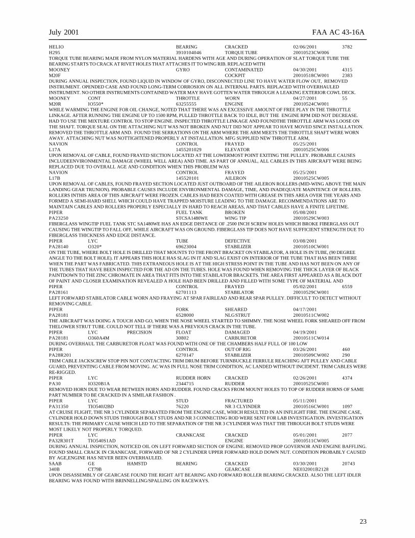
July 2001 FAA AC 43-16A
HELIO BEARING CRACKED 02/06/2001 3782H295 3910104046 TORQUE TUBE 20010523CW006TORQUE TUBE BEARING MADE FROM NYLON MATERIAL HARDENS WITH AGE AND DURING OPERATION OF SLAT TORQUE TUBE THEBEARING STARTS TO CRACK AT RIVET HOLES THAT ATTACHES IT TO WING RIB. REPLACED WITHMOONEY GYRO CONTAMINATED 04/30/2001 4315M20F COCKPIT 20010518CW001 2383DURING ANNUAL INSPECTION, FOUND LIQUID IN WINDOW OF GYRO, DISCONNECTED LINE TO HAVE WATER FLOW OUT, REMOVEDINSTRUMENT. OPENDED CASE AND FOUND LONG-TERM CORROSION ON ALL INTERNAL PARTS. REPLACED WITH OVERHAULEDINSTRUMENT. NO OTHER INSTRUMENTS CONTAINED WATER MAY HAVE GOTTEN WATER THROUGH A LEAKING EXTERIOR COWL DECK.MOONEY CONT THROTTLE WORN 04/27/2001 55M20R IO550* 63255555 ENGINE 20010524CW001WHILE WARMING THE ENGINE FOR OIL CHANGE, NOTED THAT THERE WAS AN EXCESSIVE AMOUNT OF FREE PLAY IN THE THROTTLELINKAGE. AFTER RUNNING THE ENGINE UP TO 1500 RPM, PULLED THROTTLE BACK TO IDLE, BUT THE ENGINE RPM DID NOT DECREASE.HAD TO USE THE MIXTURE CONTROL TO STOP ENGINE. INSPECTED THROTTLE LINKAGE AND FOUNDTHE THROTTLE ARM WAS LOOSE ONTHE SHAFT. TORQUE SEAL ON THE ATTACHING NUT WAS NOT BROKEN AND NUT DID NOT APPEAR TO HAVE MOVED SINCE INSTALLATION.REMOVED THE THROTTLE ARM AND. FOUND THE SERRATIONS ON THE ARM WHERE THE ARM MEETS THE THROTTLE SHAFT WERE WORNAWAY. ATTACHING NUT WAS NOTTIGHTENED PROPERLY AT INSTALLATION. MFG SUPPLIED NEW THROTTLE ARM,NAVION CONTROL FRAYED 05/25/2001L17A 1455201029 ELEVATOR 20010525CW006UPON REMOVAL OF CABLE, FOUND FRAYED SECTION LOCATED AT THE LOWERMOST POINT EXITING THE PULLEY. PROBABLE CAUSESINCLUDEENVIRONMENTAL DAMAGE (WHEEL WELL AREA) AND TIME. AS PART OF ANNUAL, ALL CABLES IN THIS AIRCRAFT WERE BEINGREPLACED DUE TO OVERALL AGE AND CONDITION WHEN THIS PROBLEM WASNAVION CONTROL FRAYED 05/25/2001L17B 145520101 AILERON 20010525CW005UPON REMOVAL OF CABLES, FOUND FRAYED SECTION LOCATED JUST OUTBOARD OF THE AILERON ROLLERS (MID-WING ABOVE THE MAINLANDING GEAR TRUNION). PROBABLE CAUSES INCLUDE ENVIRONMENTAL DAMAGE, TIME, AND INADEQUATE MAINTENCE OF ROLLERS.ROLLERS INTHIS AREA OF THIS AIRCRAFT WERE FROZEN. CABLES HAD BEEN COATED WITH GREASE IN THIS AREA OVER THE YEARS ANDFORMED A SEMI-HARD SHELL WHICH COULD HAVE TRAPPED MOISTURE LEADING TO THE DAMAGE. RECOMMENDATIONS ARE TOMAINTAIN CABLES AND ROLLERS PROPERLY ESPECIALLY IN HARD TO REACH AREAS, AND THAT CABLES HAVE A FINITE LIFETIME.PIPER FUEL TANK BROKEN 05/08/2001PA23250 STCSA1480WE WING TIP 20010529CW003FIBERGLASS WINGTIP FUEL TANK STC SA1480WE HAS AN EDGE DISTANCE OF .2500 INCH SCREW HOLES WHICH BROKE FIBERGLASS OUTCAUSING THE WINGTIP TO FALL OFF, WHILE AIRCRAFT WAS ON GROUND. FIBERGLASS TIP DOES NOT HAVE SUFFICIENT STRENGTH DUE TOFIBERGLASS THICKNESS AND EDGE DISTANCE.PIPER LYC TUBE DEFECTIVE 03/08/2001PA28140 O320* 69623004 STABILIZER 20010510CW001ON THE TUBE, WHERE BOLT HOLE IS DRILLED THAT MOUNTS TO THE FRONT BRACKET ON STABILATOR, A HOLE IS IN TUBE, (90 DEGREEANGLE TO THE BOLT HOLE). IT APPEARS THIS HOLE HAS SLAG IN IT AND SLAG EXIST ON INTERIOR OF THE TUBE THAT HAS BEEN THEREWHEN THE PART WAS FABRICATED. THIS EXTRANEOUS HOLE IS AT THE HIGH STRESS POINT IN THE TUBE AND HAS NOT BEEN ON ANY OFTHE TUBES THAT HAVE BEEN INSPECTED FOR THE AD ON THE TUBES. HOLE WAS FOUND WHEN REMOVING THE THICK LAYER OF BLACKPAINTDOWN TO THE ZINC CHROMATE IN AREA THAT FITS INTO THE STABILATOR BRACKETS. THE AREA FIRST APPEARED AS A BLACK DOTOF PAINT AND CLOSER EXAMINATION REVEALED A HOLE HAD BEEN DRILLED AND FILLED WITH SOME TYPE OF MATERIAL ANDPIPER CONTROL FRAYED 05/02/2001 6559PA28161 62701113 STABILATOR 20010529CW001LEFT FORWARD STABILATOR CABLE WORN AND FRAYING AT SPAR FAIRLEAD AND REAR SPAR PULLEY. DIFFICULT TO DETECT WITHOUTREMOVING CABLE.PIPER FORK SHEARED 04/17/2001PA28181 6528000 NLG STRUT 20010511CW002THE AIRCRAFT WAS DOING A TOUCH AND GO, WHEN THE NOSE WHEEL STARTED TO SHIMMY. THE NOSE WHEEL FORK SHEARED OFF FROMTHELOWER STRUT TUBE. COULD NOT TELL IF THERE WAS A PREVIOUS CRACK IN THE TUBE.PIPER LYC PRECISION FLOAT DAMAGED 04/19/2001PA28181 O360A4M 30802 CARBURETOR 20010511CW014DURING OVERHAUL THE CARBURETOR FLOAT WAS FOUND WITH ONE OF THE CHAMBERS HALF FULL OF 100 LOWPIPER CONTROL OUT OF RIG 03/26/2001 460PA28R201 6270147 STABILIZER 20010509CW002 290TRIM CABLE JACKSCREW STOP PIN NOT CONTACTING TRIM DRUM BEFORE TURNBUCKLE FERRULE REACHING AFT PULLEY AND CABLEGUARD, PREVENTING CABLE FROM MOVING. AC WAS IN FULL NOSE TRIM CONDITION, AC LANDED WITHOUT INCIDENT. TRIM CABLES WERERE-RIGGED.PIPER LYC RUDDER HORN CRACKED 02/26/2001 4374PA30 IO320B1A 2344715 RUDDER 20010525CW001REMOVED HORN DUE TO WEAR BETWEEN HORN AND RUDDER. FOUND CRACKS FROM MOUNT HOLES TO TOP OF RUDDER HORNS OF SAMEPART NUMBER TO BE CRACKED IN A SIMILAR FASHION .PIPER LYC STUD FRACTURED 05/11/2001PA31350 TIO540J2BD 76220 NR 3 CLYINDER 20010516CW001 1097AT CRUISE FLIGHT, THE NR 3 CYLINDER SEPARATED FROM THE ENGINE CASE, WHICH RESULTED IN AN INFLIGHT FIRE. THE ENGINE CASE,CYLINDER HOLD DOWN STUDS THROUGH BOLT STUDS AND NR 3 CONNECTING ROD WERE SENT FOR LAB INVESTIGATION. INVESTIGATIONRESULTS: THE PRIMARY CAUSE WHICH LED TO THE SEPARATION OF THE NR 3 CYLINDER WAS THAT THE THROUGH BOLT STUDS WEREMOST LIKELY NOT PROPERLY TORQUED.PIPER LYC CRANKCASE CRACKED 05/01/2001 2077PA32R301T TIO540S1AD ENGINE 20010511CW005DURING ANNUAL INSPECTION, NOTICED OIL ON LEFT FORWARD SECTION OF ENGINE. REMOVED PROP GOVERNOR AND ENGINE BAFFLING.FOUND SMALL CRACK IN CRANKCASE, FORWARD OF NR 2 CYLINDER UPPER FORWARD HOLD DOWN NUT. CONDITION PROBABLY CAUSEDBY AGE,ENGINE HAS NEVER BEEN OVERHAULED.SAAB GE HAMSTD BEARING CRACKED 03/30/2001 20743340B CT79B GEARCASE NE032001B2128UPON DISASSEMBLY OF GEARCASE FOUND THE RIGHT AFT BEARING AND FORWARD ROLLER BEARING CRACKED. ALSO THE LEFT IDLERBEARING WAS FOUND WITH BRINNELLING/SPALLING ON RACEWAYS.
24
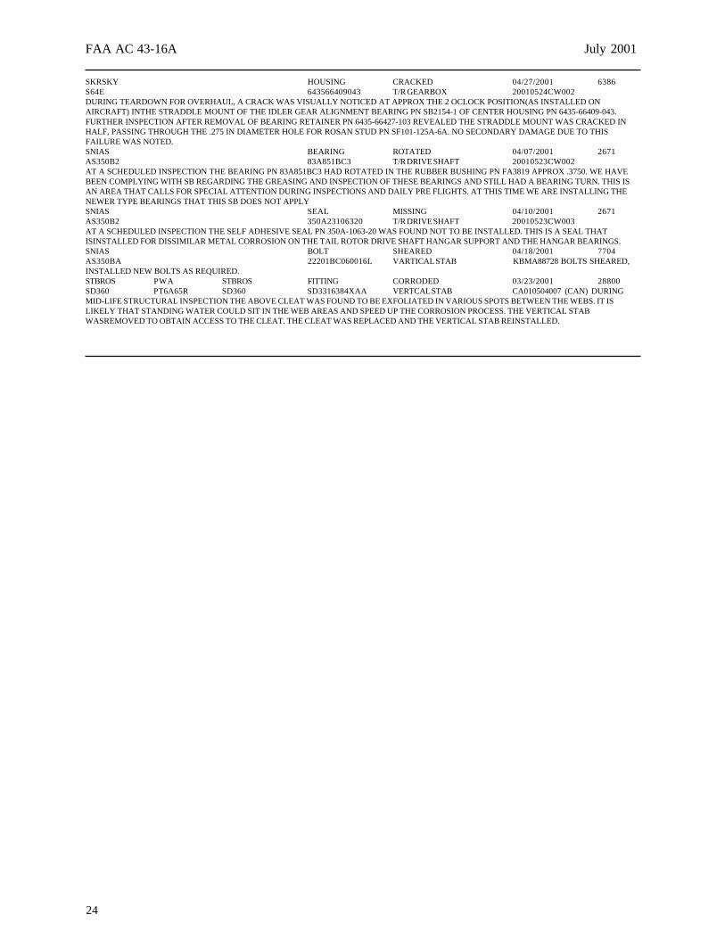
FAA AC 43-16A July 2001
SKRSKY HOUSING CRACKED 04/27/2001 6386S64E 643566409043 T/R GEARBOX 20010524CW002DURING TEARDOWN FOR OVERHAUL, A CRACK WAS VISUALLY NOTICED AT APPROX THE 2 OCLOCK POSITION(AS INSTALLED ONAIRCRAFT) INTHE STRADDLE MOUNT OF THE IDLER GEAR ALIGNMENT BEARING PN SB2154-1 OF CENTER HOUSING PN 6435-66409-043.FURTHER INSPECTION AFTER REMOVAL OF BEARING RETAINER PN 6435-66427-103 REVEALED THE STRADDLE MOUNT WAS CRACKED INHALF, PASSING THROUGH THE .275 IN DIAMETER HOLE FOR ROSAN STUD PN SF101-125A-6A. NO SECONDARY DAMAGE DUE TO THISFAILURE WAS NOTED.SNIAS BEARING ROTATED 04/07/2001 2671AS350B2 83A851BC3 T/R DRIVE SHAFT 20010523CW002AT A SCHEDULED INSPECTION THE BEARING PN 83A851BC3 HAD ROTATED IN THE RUBBER BUSHING PN FA3819 APPROX .3750. WE HAVEBEEN COMPLYING WITH SB REGARDING THE GREASING AND INSPECTION OF THESE BEARINGS AND STILL HAD A BEARING TURN. THIS ISAN AREA THAT CALLS FOR SPECIAL ATTENTION DURING INSPECTIONS AND DAILY PRE FLIGHTS. AT THIS TIME WE ARE INSTALLING THENEWER TYPE BEARINGS THAT THIS SB DOES NOT APPLYSNIAS SEAL MISSING 04/10/2001 2671AS350B2 350A23106320 T/R DRIVE SHAFT 20010523CW003AT A SCHEDULED INSPECTION THE SELF ADHESIVE SEAL PN 350A-1063-20 WAS FOUND NOT TO BE INSTALLED. THIS IS A SEAL THATISINSTALLED FOR DISSIMILAR METAL CORROSION ON THE TAIL ROTOR DRIVE SHAFT HANGAR SUPPORT AND THE HANGAR BEARINGS.SNIAS BOLT SHEARED 04/18/2001 7704AS350BA 22201BC060016L VARTICAL STAB KBMA88728 BOLTS SHEARED,INSTALLED NEW BOLTS AS REQUIRED.STBROS PWA STBROS FITTING CORRODED 03/23/2001 28800SD360 PT6A65R SD360 SD3316384XAA VERTCAL STAB CA010504007 (CAN) DURINGMID-LIFE STRUCTURAL INSPECTION THE ABOVE CLEAT WAS FOUND TO BE EXFOLIATED IN VARIOUS SPOTS BETWEEN THE WEBS. IT ISLIKELY THAT STANDING WATER COULD SIT IN THE WEB AREAS AND SPEED UP THE CORROSION PROCESS. THE VERTICAL STABWASREMOVED TO OBTAIN ACCESS TO THE CLEAT. THE CLEAT WAS REPLACED AND THE VERTICAL STAB REINSTALLED.
DEPARTMENT OF TRANSPORTATION
OMB No. 2120-0003
FEDERAL AVIATION ADMINISTRATION
MALFUNCTION OR DEFECT REPORT
AIRCRAFT
POWERPLANT
PROPELLER
Enter pertinent data MANUFACTURER
FAA Form 8010-4 (10-92) SUPERSEDES PREVIOUS EDITIONS
MODEL/SERIES SERIAL NUMBER
ATA Code
A/C Reg. No. N-
OPER. Control No.
1.
2.
3.
Part Name
Comp/Appl Name Manufacturer Model or Part No. Serial Number
Check a box below, if this report is related to an aircraft7. Date Sub.
8. Comments (Describe the malfunction or defect and the circumstances under which it occurred. State probable cause and recommendations to prevent recurrence.)
Part TT Part TSO Part Condition
Serial No. Part/Defect Location.MFG. Model or Part No.
4.
5. SPECIFIC PART (of component) CAUSING TROUBLE
6. APPLIANCE/COMPONENT (Assembly that includes part)
Accident; Date
Optional Information:
Incident; Date
REP.
STA
.
SUBM
ITTE
D BY
:
TELE
PHO
NE N
UMBE
R:
OPE
R.M
ECH.
AIR
TAXI
MFG
.FA
AO
THER
COM
MUT
ERDI
STRI
CTO
FFIC
E
OPE
RATO
RDE
SIG
NATO
R
(
)
Use this space for continuation of Block 8 (if required).
U.S. Departmentof Transportation
Federal AviationAdministration
Flight Standards ServiceMaintenance Support BranchP.O. Box 25082Oklahoma City, OK 73125
AFS-640
Official BusinessPenalty for Private Use $300
NO POSTAGENECESSARY
IF MAILEDIN THE
UNITED STATES
BUSINESS REPLY MAILFIRST CLASS PERMIT NO. 12438 WASHINGTON, D.C.
Federal Aviation AdministrationAFS-640 (Alerts)P.O. Box 25082Oklahoma City, OK 73125-5029
U.S. Departmentof TransportationFederal AviationAdministration
Flight Standards ServiceDesignee Standardization BranchP.O. Box 25082Oklahoma City, OK 73125-5029
Official BusinessPenalty for PrIvate Use $300
AFS-640